1 cavity decay rate in presence of a slow-light medium thomas lauprêtre fabienne goldfarb fabien...
Post on 19-Dec-2015
216 views
TRANSCRIPT

1
Cavity decay rate in presence of a Slow-Light
mediumThomas LauprêtreFabienne GoldfarbFabien Bretenaker
Laboratoire Aimé Cotton, Orsay, France
School of Physical Sciences, Jawaharlal Nehru University, Delhi, India
Rupamanjari GhoshSantosh Kumar
Thales R&T, Palaiseau, France
Sylvain Schwartz

2
Outline
• Issues: the ring laser gyro• EIT and dispersion• Experimental set-up• Cavity decay rate• Negative dispersion in He*

3
Inertial navigation
Start
Problem: allow a vehicle to know its attitude and position at any moment by knowing only the coordinates of its starting point and using internal measurements only.
Solution: continuously measure three linear accelerations and three angular velocities.
?ax
ay
az
x
y z
Error smaller than 1 nautical mile per hour: Drift of the gyros < 0.01 °/hour
(Earth rotation≈ 15 °/ hour)
Till the 1960’s: undisputed reign of mechanical gyros!

4
Sagnac effect
O
L+- L- = 4πR2Ω/c
O’
R = 0.1 m et Ω = 0.01
°/h
Δφ < 1
nanoradian
CW WaveCCW Wave

5
Principle of the ring laser gyro
Gain mediumCW Modes
CCW Modes
c/L
L
A
4
CCW Wave
CW Wave

6
Dispersion in cavity
Positive dispersion reduces the linewidth of a resonator
Could dispersion enhance sensitivity of cavity based sensors?

7
Cavity filled with a dispersive medium
Dispersive medium
Ln
cp
L
L
n
n
L
d
dnn
d
dnnng
L
L
n
n
g
Cavity resonance condition:
Sagnac effect:
with
with
If , Sensitivity 0gn

8
The fundamental noise is given by the
Schawlow-Townes linewidth of the
laser:2
1
4 cavoutP
h
triproundper Losses
duration tripround
cav
Ring laser gyro
Lifetime of photons in the cavity

9
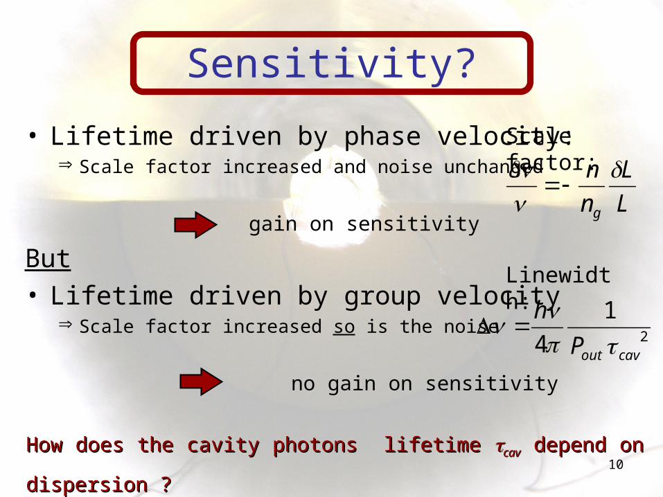
Lifetime of photons
• 2 different points of view
1) Phase velocity Resonant cavity:monochromatic field
2) Group velocityGaussian pulseΔt ∞ ?
Δt
10
• Lifetime driven by phase velocity: Scale factor increased and noise unchanged
gain on sensitivity
But• Lifetime driven by group velocity
Scale factor increased so is the noise
no gain on sensitivity
2
1
4 cavoutP
h
Sensitivity?
L
L
n
n
g
Scale factor:
Linewidth:
How does the cavity photons lifetime How does the cavity photons lifetime cavcav depend on depend on
dispersion ?dispersion ?

11
Outline
• Issues: the ring laser gyro• EIT and dispersion• Experimental set-up• Cavity decay rate• Negative dispersion in He*
12
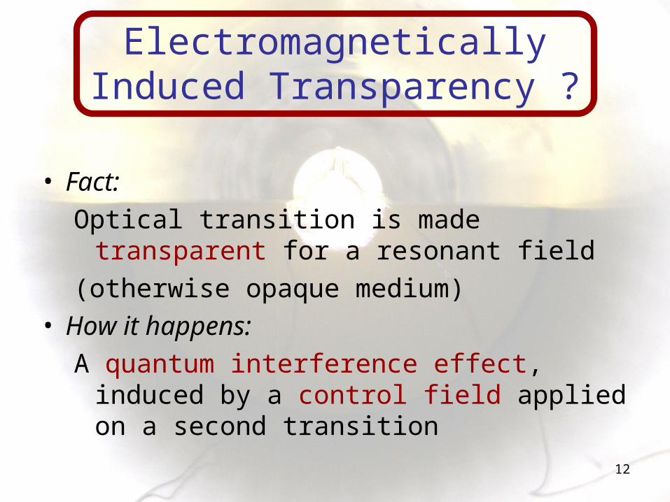
Electromagnetically Induced Transparency ?
• Fact:Optical transition is made transparent for
a resonant field (otherwise opaque medium)
• How it happens:A quantum interference effect, induced by
a control field applied on a second transition

13
cp c
One optical transitionΛ system
ab
cR 2
22
p
Rc b
a
ab
Electromagnetically Induced Transparency (EIT)
Width of transparency window
R
cbR
relax
cb
t

14
EIT and Slow Light
• Kramers-Kronig
Strong positive dispersion
d
dn
cvg )Re(
2
Slow Light !
Kash & al, PRL, 1999: 90 m.s-1 in RbHau & al, Nature, 1999: 17 m.s-1 in cold
Na

15
Outline
• Issues: the ring laser gyro• EIT and dispersion• Experimental set-up• Cavity decay rate• Negative dispersion in He*

16
Metastable 4He
1S0
3P1
3S1
m = -1 10
RF discharge
p p
0
12
c
c
• Lifetime ~8000s
polarization selected Λ system

17
• Spin conservation through collisions with He
M. Pinard and F. Laloë, J. Physique 41 799 (1980)
• Almost no Penning ionization (thanks to optical pumping)
Shlyapnikov & al, PRL 73 3247 (1994)
Room temperature 4He*
No loss of coherence time
18
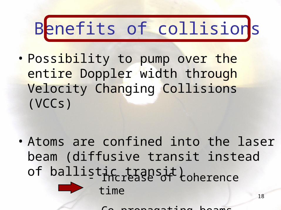
• Possibility to pump over the entire Doppler width through Velocity Changing Collisions (VCCs)
• Atoms are confined into the laser beam (diffusive transit instead of ballistic transit)
Benefits of collisions
- Increase of coherence time
- Co-propagating beams

19
CcaC
EIT and optical detuning
R
ccp
c b
a
ab
RC
Fano profile B. Lounis and C. Cohen-Tannoudji, J. Phys. II (France) 2, 579 (1992)
CPR

20
Doppler broadening• Sum of all profiles over the Doppler width
ab
cR 2
22
D
cR W2
22
Where WD is the half linewidth of the Doppler profile
3P1
Doppler width
~1 GHzR
~ ~Couplingc
Probep
3S1

21
Experimental set-up

22
Experimental results
D
cR W2
22
Coupling intensity (W.m-2)
Wid
th a
t h
alf
ma
xim
um
(k
Hz)
Gro
up
de
lay
(µ
s)
Coupling intensity (W.m-2)
Group velocity around 8 km.s-1 !Goldfarb, F. & al.,
EPL (Europhysics Letters), 2008, 82, 54002
Ghosh, J. & al., Phys.Rev.A, 2009
Im(χ
) (a
.u.)
Raman detuning (kHz)

23
Outline
• Issues: the ring laser gyro• EIT and dispersion• Experimental set-up• Cavity decay rate• Negative dispersion in He*

24
EIT inside a cavity: set-up
λ/2 AO1
AO2
PBS
ωP , ΩP
ωC , ΩC
Laser & Beam
Shaping
PD
Telescope
4He* cell
PBS
PZ
Shutter
PBS
T=2% T=2%

25
Experiment

26
Global results
Decay time of the cavity Group delay introduced by the cell (open cavity)
• Measured decay time ~ a few µs • ~150 ns with phase velocity
Group velocity !

27
Cavity decay rate
cav1
cav
lossesgroup
cav
• Non monochromatic field
Group velocity
T. Lauprêtre, C. Proux, R. Ghosh, S. Schwartz, F. Goldfarb, and F. Bretenaker« Photon lifetime in a cavity containing a slow-light medium »Accepted by OL

28
Cavity decay rate
• Consequences on the fundamental noise of laser cavity based sensors?
Increase of Δν
L
L
n
n
g
0gn
2
1
4 cavoutP
h
0cav

29
• Lifetime ?
Negative dispersion in cavity
Δt
Vg>0

30
• Lifetime ?
Negative dispersion in cavity
Δt
Vg<0
tripround 1 f or 0group

31
Outline
• Issues: the ring laser gyro• EIT and dispersion• Experimental set-up• Cavity decay rate• Negative dispersion in He*

32
Negative dispersion
• Optical detuning : asymmetry of the absorption profile
Narrow absorption peak of small amplitude
Negative dispersion
3P1
Doppler width
~1 GHzR
~ ~Couplingc
Probep
3S1
Δ

33
Raman detuning (kHz)
Negative group velocity
Raman detuning (kHz)
Gro
up
del
ay (
µs)
3P1
Doppler width
~1 GHz
R
~ ~Coupling
c
Probep
3S1
Δ

34
Conclusion
• Decay rate of a cavity filled with a strong positive dispersion medium is governed by the group velocity
• Negative group velocity?

35
Poster session: Tu-P15 S. Kumar, T. Lauprêtre, F. Bretenaker, R. Ghosh, and F.
GoldfarbInteracting dark resonances in a tripod system of room
temperature 4He*
Advertisment

36
Thank you!