aptatcip.comaptatcip.com/archives_files/01282005_195917tcip_doc_v_2.6_vol_i… · web...
TRANSCRIPT
11/24/04 TCIP V 2.6.1
APTA TCIP-S-001 D2.6.1, APTA Draft Standard for
Transit Communications Interface Profiles
Version 2.6.1
Volume I Narrative
American Public Transportation Association

11/24/04 TCIP V 2.6.1
APTA TCIP-S-001 D2.6.1, APTA Draft Standard for Transit Communications Interface Profiles ii
This is a draft Standard intended for review by the TCIP Technical Working Groups and other interested industry parties. It has not been approved and does not reflect APTA or USDOT policy.
This document was developed by APTA under contract to the Federal Transit Administration. Support was provided by two principal subcontractors to APTA: ARINC Inc. and Critical Link LLC, in cooperation with the APTA TCIP Technical Working Groups. The APTA TCIP Technical Working Groups and industry review efforts are overseen by the APTA TCIP Task Force, co-chaired by Isaac Takyi and Jerome Lutin.
The APTA TCIP Executive Review Committee is chaired by John Bartosiewicz, Executive Vice President/COO of McDonald Transit Associates, Inc., formerly the General Manager of Fort Worth Transit.
This document contains material originally published in the NTCIP 1400 series standards, some of which has been modified or adapted for TCIP Version 2.6. TCIP Version 2.6 contains substantial changes from Version 2.5, many of which are the result of comments received from the TCIP Technical Working Groups and other members of the transit industry.
Inquiries regarding this document should be directed to Louis Sanders of APTA (202) 496-4886.

11/24/04 TCIP V 2.6.1
Contents
1. Overview.............................................................................................................................................. 1
1.1 Purpose of the TCIP Standard......................................................................................................... 1
1.2 Major Features of TCIP.................................................................................................................. 3
1.3 TCIP Background and History........................................................................................................ 4
1.4 Document Overview....................................................................................................................... 5
2. References and Definitions................................................................................................................... 6
2.1 References...................................................................................................................................... 6
2.1.1 Normative References.............................................................................................................. 6
2.1.2 Informative References............................................................................................................ 6
2.2 Definitions...................................................................................................................................... 9
3. TCIP Data.......................................................................................................................................... 27
3.1 Data Elements............................................................................................................................... 28
3.2 TCIP Data Frames........................................................................................................................ 29
3.3 TCIP Messages............................................................................................................................. 31
4. Understanding TCIP........................................................................................................................... 32
4.1 Structure of TCIP.......................................................................................................................... 33
4.2 TCIP Model Architecture..............................................................................................................35
4.2.1 Overview............................................................................................................................... 35
4.2.2 Business Systems................................................................................................................... 39
4.2.3 Public Transit Vehicles..........................................................................................................42
4.2.4 Supervisors and Maintenance Vehicles...................................................................................49
4.2.5 Transit Field Systems............................................................................................................. 50
4.2.6 Transit Agency External Communications..............................................................................52
4.2.7 Model Architecture Communications.....................................................................................55
4.2.8 Dialog and File Transfer Flow Line Conventions...................................................................55
APTA TCIP-S-001 D2.6.1, APTA Draft Standard for Transit Communications Interface Profiles iii
This is a draft Standard intended for review by the TCIP Technical Working Groups and other interested industry parties. It has not been approved and does not reflect APTA or USDOT policy.

11/24/04 TCIP V 2.6.1
4.3 Data Configuration Management..................................................................................................58
4.3.1 Identification of Artifacts.......................................................................................................58
4.3.2 Rows within Artifacts.............................................................................................................58
4.3.3. Relationship to Dialog Patterns and File Transfers................................................................59
4.3.4 Applicability.......................................................................................................................... 59
4.4 TCIP Dialogs................................................................................................................................ 60
4.4.1 Dialog Patterns....................................................................................................................... 60
4.4.2 Dialog Instantiations.............................................................................................................. 60
4.5 TCIP File Transfer........................................................................................................................ 61
5. Concept of Operations........................................................................................................................ 62
5.1 General Concepts.......................................................................................................................... 62
5.2 Security and Incident Management...............................................................................................63
5.2.1 Purpose.................................................................................................................................. 63
5.2.2 Overview of Security and Incident Management....................................................................63
5.2.3 Primary Architecture Components..........................................................................................64
5.2.4 Security and Incident Management Process Stages.................................................................64
5.2.4.1 Security and Incident Management Planning Stage..............................................................64
5.2.4.2 Security and Incident Management Preparation Stage..........................................................69
5.2.4.3 Incident Detection, Classification, and Verification Stage...................................................69
5.2.4.4 Incident Notification........................................................................................................... 73
5.2.4.5 Security and Incident Response...........................................................................................75
5.2.4.5.1 External Agencies.....................................................................................................76
5.2.4.5.2 View Video Images at the Incident Location.............................................................78
5.2.4.5.3 Receiving and Distributing Incident Updates............................................................79
5.2.4.5.4 Implement and Cancel Detours.................................................................................82
5.2.4.5.5 Exchange Text Messages..........................................................................................82
APTA TCIP-S-001 D2.6.1, APTA Draft Standard for Transit Communications Interface Profiles iv
This is a draft Standard intended for review by the TCIP Technical Working Groups and other interested industry parties. It has not been approved and does not reflect APTA or USDOT policy.

11/24/04 TCIP V 2.6.1
5.2.4.5.6 Monitor and Cancel Silent Alarms............................................................................83
5.2.4.5.7 Voice Communications between Dispatchers and PTV Operators.............................83
5.2.4.5.8 Change Vehicle or Operator Assignments.................................................................84
5.2.4.5.9 Dispatch Agency Responders....................................................................................86
5.2.4.5.10 Disable a PTV......................................................................................................... 86
5.2.4.5.11 Cancel Trips...........................................................................................................87
5.2.4.6 Incident Recovery............................................................................................................... 87
5.2.4.7 Incident Follow Up..............................................................................................................88
5.3 PTV Operations............................................................................................................................ 91
5.3.1 Purpose.................................................................................................................................. 91
5.3.2 Overview of PTV Operations.................................................................................................91
5.3.3 Primary Architecture Components..........................................................................................91
5.3.4 Vehicle Operations Subprocesses...........................................................................................92
5.3.4.1 Preparation for Vehicle Operations..................................................................................92
5.3.4.1.1 Data Loading............................................................................................................ 92
5.3.4.1.2 Vehicle Startup......................................................................................................... 96
5.3.4.1.3 Operator Sign-On and Inspection..............................................................................96
5.3.4.1.4 Pull Out.................................................................................................................. 101
5.3.4.2 Normal PTV Operations................................................................................................103
5.3.4.2.1 PTV Movements.....................................................................................................103
5.3.4.2.1.1 Deadhead to Initial Terminal................................................................................103
5.3.4.2.1.2 In-Service Trips...................................................................................................103
5.3.4.2.1.3 Post In-Service Trips............................................................................................104
5.3.4.2.2 PTV Location Tracking.............................................................................................104
5.3.4.2.3 PTV Operator Changes...............................................................................................108
5.3.4.2.3.1 Scheduled Operator Changes................................................................................108
APTA TCIP-S-001 D2.6.1, APTA Draft Standard for Transit Communications Interface Profiles v
This is a draft Standard intended for review by the TCIP Technical Working Groups and other interested industry parties. It has not been approved and does not reflect APTA or USDOT policy.

11/24/04 TCIP V 2.6.1
5.3.4.2.3.2 Unscheduled Operator Changes............................................................................109
5.3.4.2.4 Enroute Communications with Dispatcher..................................................................109
5.3.4.2.4.1 Voice Communications........................................................................................109
5.3.4.2.4.2 Data Communications..........................................................................................113
5.3.4.2.5 PTV Health and Parameter Monitoring.......................................................................115
5.3.4.2.6 Transit Signal Priority (TSP).......................................................................................117
5.3.4.2.6.1 Priority Request Scenario 1..................................................................................123
5.3.4.2.6.2 Priority Request Scenario 2..................................................................................125
5.3.2.6.3 Priority Request Scenario 3.....................................................................................126
5.3.4.2.6.4 Priority Request Scenario 4..................................................................................126
5.3.4.2.6.5 Priority Request Scenario 5..................................................................................127
5.3.4.2.7 MDT Menu Sharing....................................................................................................128
5.3.4.2.8 Passenger Counting.....................................................................................................129
5.3.4.2.9 Traveler Request Inputs into PTV Operations..........................................................130
5.3.4.2.9.1 Transfer Connection Protection............................................................................130
5.3.4.2.9.2 On Demand Wheelchair Requests........................................................................132
5.3.4.2.10 PTV Annunciator..................................................................................................133
5.3.4.3 Exceptions to Normal Operations......................................................................................134
5.3.4.3.1 Route Adherence........................................................................................................ 134
5.3.4.3.2 Schedule Adherence...................................................................................................135
5.3.4.3.3 Enroute Trip Changes.............................................................................................137
5.3.4.3.4 Canceling Scheduled Trips......................................................................................139
5.3.4.3.5 Reporting Service Events........................................................................................140
5.3.4.4 Close Out of Normal Operations........................................................................................140
5.3.4.4.1 Recording the Pull-In..................................................................................................140
5.3.4.4.2 Removing Cash and Tokens........................................................................................142
APTA TCIP-S-001 D2.6.1, APTA Draft Standard for Transit Communications Interface Profiles vi
This is a draft Standard intended for review by the TCIP Technical Working Groups and other interested industry parties. It has not been approved and does not reflect APTA or USDOT policy.

11/24/04 TCIP V 2.6.1
5.3.4.4.3 Unloading Data from the PTV....................................................................................142
5.3.4.4.4 Logoff and Shutdown..................................................................................................144
5.3.4.4.5 Non PTV Closeouts....................................................................................................145
5.4 Fare Collection and Revenue Management..................................................................................147
5.4.1 Purpose of Fare Collection and Revenue Management.........................................................147
5.4.2 Overview of Fare Collection and Revenue Management.......................................................147
5.4.3 Primary Architectural Components.......................................................................................149
5.4.4 Constituent Processes of Fare Collection and Revenue Management....................................149
5.4.4.1 Fare Policy.................................................................................................................... 150
5.4.4.2 Fare Media Sales/Vending.............................................................................................152
5.4.4.3 Revenue/Media Collection.............................................................................................152
5.4.4.4 Revenue Reconciliation.................................................................................................153
5.4.4.5 Banking......................................................................................................................... 155
5.4.4.6 Fare Collection and Revenue Management Security......................................................156
5.4.4.7 Fare/Revenue System Maintenance................................................................................156
5.4.4.8 Fare System Configuration............................................................................................157
5.5 Scheduling.................................................................................................................................. 159
5.5.1 Purpose of Business Process.................................................................................................159
5.5.2 Overview of Scheduling Process...........................................................................................159
5.5.3 Primary Model Architecture Components.............................................................................162
5.5.4 Constituent Processes of Scheduling.....................................................................................162
5.5.4.1 Data Gathering for Schedule Writing.............................................................................162
5.5.4.2 Developing Scheduling Products....................................................................................164
5.5.4.3 Distributing Scheduling Products...................................................................................166
5.6 Personnel Management and Assignments....................................................................................173
5.6.1 Purpose of Personnel Management and Assignments............................................................173
APTA TCIP-S-001 D2.6.1, APTA Draft Standard for Transit Communications Interface Profiles vii
This is a draft Standard intended for review by the TCIP Technical Working Groups and other interested industry parties. It has not been approved and does not reflect APTA or USDOT policy.

11/24/04 TCIP V 2.6.1
5.6.2 Overview.............................................................................................................................. 173
5.6.3 Primary Architecture Component.........................................................................................173
5.6.4 Operator Assignment Processes............................................................................................173
5.6.4.1 Operator Assignment Definition....................................................................................173
5.6.4.2 Pick Process................................................................................................................... 176
5.6.4.3 Distribution of Bound Assignments...............................................................................176
5.6.4.4 Changes to Operator Assignments..................................................................................176
5.7 Asset Management...................................................................................................................... 178
5.7.1 Purpose of the Asset Management Business Process.............................................................178
5.7.2 Overview of Asset Management...........................................................................................178
5.7.3 Primary Model Architecture Components.............................................................................179
5.7.4 Asset Management Processes...............................................................................................179
5.7.4.1 PTV Pull In to Garage...................................................................................................179
5.7.4.2 Fuelling......................................................................................................................... 179
5.7.4.3 Cleaning........................................................................................................................ 180
5.7.4.4 Scheduled Service and Inspections.................................................................................180
5.7.4.5 Unscheduled Maintenance.............................................................................................180
5.7.4.6 Overhaul/Contactor/Manufacturer Maintenance.............................................................181
5.7.4.7 Garage Parking Management & Vehicle Assignment.....................................................181
5.7.4.8 Pull Out Process............................................................................................................183
5.7.4.9 En Route Failures..........................................................................................................183
5.7.4.10 Synchronization/Calibration.........................................................................................185
5.8 Customer Information.................................................................................................................187
5.8.1 Purpose of Customer Information Business Process..............................................................187
5.8.2 Overview of Customer Information Business Process...........................................................187
5.8.3 Primary Model Architecture Component Roles in Customer Information.............................189
APTA TCIP-S-001 D2.6.1, APTA Draft Standard for Transit Communications Interface Profiles viii
This is a draft Standard intended for review by the TCIP Technical Working Groups and other interested industry parties. It has not been approved and does not reflect APTA or USDOT policy.

11/24/04 TCIP V 2.6.1
5.8.4 Customer Information Constituent Processes........................................................................190
5.8.4.1 Customer Information Pretrip Planning Process.............................................................190
5.8.4.1.1 Itinerary Generation................................................................................................191
5.8.4.1.2 Other Planning Data................................................................................................192
5.8.4.1.3 Printed Planning Material........................................................................................194
5.8.4.2 Customer Information-Station/Stop Process...................................................................195
5.8.4.3 Customer Information – Passenger Process....................................................................198
5.8.4.4 Customer Information – Ongoing Process......................................................................200
5.8.4.4.1 Customer Complaints..............................................................................................200
5.8.4.4.2 Customer Information Ongoing Process – Lost and Found......................................201
5.8.4.4.3 Customer Information Ongoing Process – Customer Subscriptions and Profiles......203
5.8.4.4.4 Customer Information Ongoing Process-Requesting Service Changes.....................204
5.9 Data Repository.......................................................................................................................... 206
5.9.1 Purpose of the Data Repository............................................................................................206
5.9.2 Overview of Data Repository Operations..............................................................................206
5.9.3 Primary Model Architecture Component..............................................................................206
5.9.4 Constituent Processes........................................................................................................... 206
5.9.4.1 Data Storage.................................................................................................................. 207
5.9.4.2 Data Validation............................................................................................................. 208
5.9.4.3 Data Fusion................................................................................................................... 210
5.9.4.4 Reporting and Archiving................................................................................................212
5.9.4.5 Data Distribution........................................................................................................... 212
5.10 Spatial Data Management.........................................................................................................215
5.10.1 Purpose of Spatial Data Management.................................................................................215
5.10.2 Overview of Spatial Data Management...............................................................................215
5.10.3 Architectural Components..................................................................................................215
APTA TCIP-S-001 D2.6.1, APTA Draft Standard for Transit Communications Interface Profiles ix
This is a draft Standard intended for review by the TCIP Technical Working Groups and other interested industry parties. It has not been approved and does not reflect APTA or USDOT policy.

11/24/04 TCIP V 2.6.1
5.10.4 Spatial Data Management Processes...................................................................................216
5.10.4.1 Spatial Translation.......................................................................................................216
5.10.4.2 Transit Map Management............................................................................................218
5.10.4.2.1 Base Map Installation............................................................................................218
5.10.4.2.2 Base Map Updates................................................................................................219
5.10.4.2.3 Transit Feature Addition.......................................................................................221
5.10.4.2.4 Transit Feature Updates........................................................................................223
5.10.4.2.5 Distribution to Transit Applications......................................................................223
5.10.4.2.6 Distribution of Map Images...................................................................................225
5.10.4.3 Device Generated and Temporal Data..........................................................................226
6 TCIP Message Encoding.................................................................................................................... 229
6.1 Encoding Schemes...................................................................................................................... 229
6.2 Narrow Band Data Communications...........................................................................................230
6.2.1 Narrowband TCIP Message Order of Octet and Bit Transmission.........................................230
6.2.2 Narrowband TCIP Message Encoding Restrictions...............................................................230
6.2.3 Narrowband TCIP Message Encoding Technique.................................................................230
6.2.3.1 Narrowband Message Header.........................................................................................231
6.2.3.2 Narrowband Message Body...........................................................................................231
6.2.3.2.1 Fixed Length Data Elements...................................................................................234
6.2.3.2.2 Variable Length Data Elements...............................................................................235
6.2.3.2.3 Enumerated Data Elements.....................................................................................237
6.2.3.2.4 Data Frames...........................................................................................................239
6.2.3.2.5 SEQUENCE OF Constructor.................................................................................241
7. TCIP Dialog Patterns........................................................................................................................ 242
7.1 Subscription Pattern.................................................................................................................... 242
7.2 Command-Response Pattern........................................................................................................248
APTA TCIP-S-001 D2.6.1, APTA Draft Standard for Transit Communications Interface Profiles x
This is a draft Standard intended for review by the TCIP Technical Working Groups and other interested industry parties. It has not been approved and does not reflect APTA or USDOT policy.

11/24/04 TCIP V 2.6.1
7.3 Report Pattern............................................................................................................................. 250
7.4 Silent Alarm Pattern.................................................................................................................... 251
7.5 Load Pattern................................................................................................................................ 253
7.6 Unload Pattern............................................................................................................................ 258
7.7 Voice Radio Call Patterns...........................................................................................................260
7.7.1 Operator Initiated Voice Radio Call Pattern..........................................................................260
7.7.2 Dispatcher Initiated Voice Radio Call Pattern.......................................................................264
7.8 Signal Control & Prioritization Dialog Pattern............................................................................266
7.9 Blind Notification Pattern........................................................................................................... 269
7.10 Push Pattern.............................................................................................................................. 270
7.11 Traveler Request Pattern........................................................................................................... 272
8. Conformance.................................................................................................................................... 275
8.2.1 Class 1 Conformance Requirements.....................................................................................276
8.2.1.1 Class 1 A Conformance Requirements...........................................................................276
8.2.1.2 Class 1 B Conformance Requirements...........................................................................276
8.2.2 Class 2 A Conformance Requirements..................................................................................277
8.2.3 Class 2 B Conformance Requirements..................................................................................277
8.3 PICS Requirements..................................................................................................................... 277
8.3.1 TCIP Version....................................................................................................................... 277
8.3.2 Conformance Class(es).........................................................................................................278
8.3.3 Network Address.................................................................................................................. 279
8.3.4 Non-conformant TCIP Features and Non-TCIP Interfaces....................................................280
8.3.5 Optional Fields for Messages................................................................................................281
8.3.6 Locally Defined Extensions..................................................................................................282
8.3.7 Conformance Class 1B Specific PICS Requirements............................................................283
8.3.8 Conformance Class 2A Specific PICS Requirements............................................................284
APTA TCIP-S-001 D2.6.1, APTA Draft Standard for Transit Communications Interface Profiles xi
This is a draft Standard intended for review by the TCIP Technical Working Groups and other interested industry parties. It has not been approved and does not reflect APTA or USDOT policy.

11/24/04 TCIP V 2.6.1
8.3.9 Conformance Class 2B Specific PICS Requirements............................................................285
9.0 Procuring TCIP Compliant Systems................................................................................................289
9.1 Agency Architecture................................................................................................................... 289
9.2 Agency RFPs.............................................................................................................................. 289
9.3 Proposals.................................................................................................................................... 290
9.4 Design Phase............................................................................................................................... 291
9.5 Factory Acceptance Test (FAT)..................................................................................................291
9.6 System Acceptance Test.............................................................................................................291
9.7 System Acceptance Test.............................................................................................................291
10 TCIP Communications................................................................................................................... 292
10.1 Overview.................................................................................................................................. 292
10.2 Fixed Point to Point Communications.......................................................................................292
10.3 Wireless Wideband Communications........................................................................................294
10.4 Wide Area (Mobile) Communications – Public Networks.........................................................295
10.5 Wide Area (Mobile) Communications – Private Networks........................................................296
Volume II
ANNEX A - Data Elements
ANNEX B - Data Frames
ANNEX C - Messages
ANNEX D - Dialogs
Volume III
ANNEX E - TCIP XML Schema
Volume IV
Annex F – This Material Intentionally Deleted
Annex G - National ITS Architecture Traceability Mapping
Annex H - Base Type Definitions
Annex I - This Material Intentionally Deleted
APTA TCIP-S-001 D2.6.1, APTA Draft Standard for Transit Communications Interface Profiles xii
This is a draft Standard intended for review by the TCIP Technical Working Groups and other interested industry parties. It has not been approved and does not reflect APTA or USDOT policy.

11/24/04 TCIP V 2.6.1
Annex J - Polling Protocol
APTA TCIP-S-001 D2.6.1, APTA Draft Standard for Transit Communications Interface Profiles xiii
This is a draft Standard intended for review by the TCIP Technical Working Groups and other interested industry parties. It has not been approved and does not reflect APTA or USDOT policy.

11/24/04 TCIP V 2.6.1
1. Overview
1.1 Purpose of the TCIP Standard
The Transit Communications Interface Profiles (TCIP) Standard constitutes the transit industry standards component of the US Intelligent Transportation Systems (ITS) program. The ITS Program is a multiyear, multimodal initiative aimed at introducing advanced technologies into transportation systems to improve the safety, security, and efficiency of those systems.
TCIP is an interface standard. Its primary purpose is to define standardized mechanisms for the exchange of information in the form of data among transit business systems, subsystems, components and devices. The standardization of these interfaces is intended to reduce the cost of future procurements of transit computer based systems, and to facilitate a greater degree of automation and integration of those systems.
TCIP recognizes that transit agencies operate differently, and have different internal architectures for their business systems, vehicles, and field systems. As a result TCIP does not mandate a single agency operating paradigm, or any agency architecture. Instead TCIP provides a rich vocabulary of possible information exchanges that agencies can use on an a-la-carte basis according to their specific business needs.
TCIP is not intended to be adopted by an agency all at once. Agencies purchase business systems, vehicles, devices and equipment intending to use them for a period of years. These systems are not replaced all at once, but rather gradually over time.
TCIP is designed to minimize the impact on transit agency operating paradigms, and on existing products and systems. TCIP allows a transit agency to implement TCIP on an incremental, modular basis by implementing only the dialogs and/or file transfers required to meet business requirements at any point in time rather than requiring wholesale conversion of all business systems to TCIP. Thus agencies can maintain legacy non-TCIP systems and interfaces in place alongside TCIP systems and interfaces, while achieving compliance with TCIP and the National ITS Architecture.
TCIP is designed to minimize the impact on supplier systems and products as well. TCIP does not specify interactions within the components produced by suppliers, or between computer applications and users. For example, if a user requests a trip itinerary from a traveler information system, TCIP does not specify the screens, user interactions, etc. TCIP does provide the dialogs or file transfers to facilitate the traveler information system obtaining schedule information from the scheduling system. TCIP also provides dialogs to allow one traveler information system to provide itinerary information to another (e.g. to another agency). TCIP uses extensible markup language (XML) to provide a widely-known and supportable data exchange format between business systems, but allows for other transfer syntaxes to be used over Narrowband communications channels.
In practice TCIP provides the tools for a transit agency to select the standard information flows required to meet its business needs, and to implement those flows cost efficiently. Information flows are standardized by defining the message formats for the exchange, as well as the dialogs that define how sequences of messages are used to implement an information flow. Some information flows can be implemented using file transfers –TCIP messages transferred in a file.
The procuring transit agency, after selecting the appropriate information flows for its needs, specifies what new and existing systems are to play what roles in what dialogs and/or file transfers. For example a traveler information system may be designated a subscriber, and a schedule repository a publisher for an information flow to convey availability of scheduled service. The procuring agency also determines what systems are authorized to access what information, and specifies what systems are responsible for controlling access. TCIP does not specify
APTA TCIP-S-001 D2.6.1, APTA Draft Standard for Transit Communications Interface Profiles 1
This is a draft Standard intended for review by the TCIP Technical Working Groups and other interested industry parties. It has not been approved and does not reflect APTA or USDOT policy.

11/24/04 TCIP V 2.6.1
the security procedures used to validate an information request, but does provide error messages to allow an unauthorized request to be rejected.
A transit agency architecture defines the systems and interfaces within a transit agency as well as the interfaces between the agency and other agencies and/or private entities. The agency architecture is the repository for capturing and documenting the agency’s legacy and planned business systems, legacy interfaces, as well as the TCIP interfaces. The agency architecture may specify a series of development phases. Each phase would represent upgrades or replacements of existing systems and interfaces, or new systems and interfaces being added. In each phase the specification of the interfaces would call out the TCIP dialogs required to be implemented by that interface and/or the legacy data flows to be at the interface.
TCIP contains a model architecture for transit as well as a transit Concept of Operations. These are not intended to be binding on any agency. Instead these sections are intended to illustrate the types of systems being interfaced with TCIP, and how those interfaces can be useful in a transit operation. Each agency that uses TCIP will find some parts of the standard which are not needed by that agency. TCIP’s a-la-carte approach allows each agency to adopt only those parts of TCIP that meet their needs.
TCIP provides a-la-carte flexibility at multiple levels:
Each dialog (automated information exchange) and file transfer defined by TCIP is individually selectable by an agency for inclusion or exclusion in the agency architecture. Some dialogs and file transfers may be inappropriate for adoption initially, and adopted later as various business systems or components are replaced.
Dialogs and file transfers are defined in terms of TCIP messages. These messages contain optional data which can be used by an individual agency, or not, based on agency policies, operating paradigms and technical requirements. TCIP messages (and their contents) include a variety of opportunities for local extensions. Local extensions allow standard messages to be used and simultaneously tailored to meet agency needs.
Each dialog or file transfer can be redirected by an agency. The TCIP Concept of Operations illustrates how dialogs and message transfers may be used to communicate among the physical and logical elements defined in the TCIP Model Architecture, however each agency is free to use these same dialogs and file transfers to convey information between any physical and logical elements in the agency or regional architecture.
TCIP defines data and messages to be exchanged in the ASN.1 language. TCIP provides an XML Schema that defines the data in a readily exchanged well-understood format. TCIP also recognizes that XML transfers are not a universal solution to transit data transmission requirements. Consequently TCIP allows for alternative transmission syntaxes to be defined by agency. Alternative syntaxes include but are no limited to zipped XML documents, ASN.1 Packed Encoding Rules, and the optional TCIP Narrowband Encoding.
TCIP messages are able to be exchanged over a variety of communications networks and physical media, TCIP does not limit an agency’s communications network architecture.
TCIP provides an extremely flexible, broad-based set of data exchange capabilities. These facilities are modular allowing agencies to select only those items required to meet their needs. Most agencies will not use all TCIP elements, but will begin adopting TCIP in phases consistent with the agency’s overall long-term systems upgrade program.
APTA TCIP-S-001 D2.6.1, APTA Draft Standard for Transit Communications Interface Profiles 2
This is a draft Standard intended for review by the TCIP Technical Working Groups and other interested industry parties. It has not been approved and does not reflect APTA or USDOT policy.

11/24/04 TCIP V 2.6.1
1.2 Major Features of TCIP
File transfers allow standardized information to be transferred from one business system to another with or without network connection. File transfers involve having one business system write files containing TCIP messages. The files are then moved to another system to be read.
Automated information transfers are defined by dialogs. Dialogs define a sequence of TCIP messages that allow TCIP enabled systems, components and devices to interact automatically based on timers, manually generated events, and automatically detected events. Implementations that begin using TCIP for file transfers may consider migrating to automated dialog based transfers as part of their planning process. Automated information transfers occur over network connections, and may occur within very short time spans following an event that causes the information transfer (real-time). In other cases, automated transfers may be deferred for operational reasons. For example, although a schedule for Tuesday of next week becomes available on Sunday, the CAD/AVL system may defer loading the schedule until Monday night.
TCIP provides an optional narrowband polling protocol which may be employed on agency-owned narrowband private radio links to communicate with transit vehicles. This protocol provides the first open systems interface available to transit for this purpose. Agencies are not obligated to adopt this protocol.
APTA TCIP-S-001 D2.6.1, APTA Draft Standard for Transit Communications Interface Profiles 3
This is a draft Standard intended for review by the TCIP Technical Working Groups and other interested industry parties. It has not been approved and does not reflect APTA or USDOT policy.

11/24/04 TCIP V 2.6.1
1.3 TCIP Background and History
The Transit Communications Interface Profile (TCIP) development effort began under the auspices of the Institute of Transportation Engineers (ITE) in cooperation with the U.S. Federal Transit Administration (FTA), the U.S. Federal Highway Administration (FHWA), and the ITS Joint Program Office. This development was performed in the context of the national Intelligent Transportation System (ITS) standards development effort and the National Transportation for ITS Protocols (NTCIP) effort of the American Association of State and Highway Transportation Officials (AASHTO), National Equipment and Manufacturing Association (NEMA), and ITE. The purpose of this effort was to provide the transit standards to support the transit segment of the ITS National Architecture. This effort produced message formats and defined data elements for the exchange of information among transit computer systems in several business areas. These standards were published by AASHTO, NEMA, and the ITE as: NTCIP 1400-1408. These standards have since been rescinded.
The definition of TCIP “dialogs” which define the rules for sending and receiving these messages was not completed as a part of this initial effort. The dialogs are a key element in developing useful standard interfaces between transit business systems. These rules create relationships between messages and systems which are essential to successful real-time interfaces. For example, the rules in the dialogs specify how a server must respond to a request for information (such as a schedule), by returning a specified information message, or a specified error message to the requester.
After completion of the initial TCIP data element and message standards, APTA was invited by the FTA to take a more prominent role in TCIP development. This resulted in the development of this document, as well as a variety of tools to support TCIP implementers. These tools are available free of charge on the Internet at http://www.arincxchange.com/exchange/login.cfm (user name: apta guest, password: apta guest).
This document subsumes the work done to date in creating the 9 NTCIP Standards, and extends this work by adding additional data elements, data frames, messages and dialogs. This document also redefines conformance to allow for limited implementations scaled to agency and project needs, and to incorporate the use of file-based transfers of transit information using TCIP messages in situations where agencies do not want or need the automated information transfers specified in the dialogs. Finally this document provides a model transit ITS architecture and Concept of Operations which are nonnormative, and intended to introduce the reader to possible uses of TCIP dialogs and file transfers in a typical transit agency.
APTA TCIP-S-001 D2.6.1, APTA Draft Standard for Transit Communications Interface Profiles 4
This is a draft Standard intended for review by the TCIP Technical Working Groups and other interested industry parties. It has not been approved and does not reflect APTA or USDOT policy.

11/24/04 TCIP V 2.6.1
1.4 Document Overview
The TCIP Standard is organized into 4 volumes. This section describes the contents of each volume.
Volume I of the TCIP Standard contains the Narrative. The narrative is divided into 10 sections as shown below: Section 1 – Overview – General Description and background of TCIP Section 2 – References and Definitions – Ties TCIP to other standards and defines terms and acronyms used
in the standard. Section 3 – TCIP Data – describes how TCIP defines data in ASN.1 and XML. Section 4 – Understanding TCIP – Provides background information and discusses the structure of TCIP
information. This section also defines the Model Architecture. Section 5 – Concept of Operations – Provides a high-level discussion of transit agency operations, and
business processes. This section ties these operations and processes to the TCIP dialogs and file transfers that support them.
Section 6 – TCIP Message Encoding – Defines TCIP supported encoding of data for transmission and defines an optional mechanism for encoding information for transfer across limited capacity communications links.
Section 7 – Dialog Patterns – This section defines the dialog patterns that are used to specify TCIP Dialogs. Dialog Patterns specify the rules for exchanging messages, message definitions define the content of messages, and dialog definitions specify a set of messages to be used according to the rules in the dialog pattern to accomplish a data transfer.
Section 8 – Conformance – Defines Conformance requirements for TCIP compliant implementations. Section 9 – TCIP Procurements – Describes how an agency can go about procuring TCIP compliant systems.
This section is informative and does not levy conformance requirements. Section 10 – TCIP Communications – Discusses communications networks used by TCIP Implementations.
This section is informative and does not levy conformance requirements.
Volume II of the TCIP Standard contains the data and dialog definitions for TCIP. This volume is organized into four annexes as shown below:
Annex A – Data Element Definitions in ASN.1 Annex B – Data Frame Definitions in ASN.1 Annex C – TCIP Message Definitions in ASN.1 Annex D – TCIP Dialog Definitions
Volume III of the TCIP Standard contains the TCIP XML Schema, which is defined to be Annex E.
Volume IV of the TCIP Standard contains additional annexes as listed below: Annex F – This material intentionally deleted Annex G – National ITS Architecture Traceability Mapping Annex H – Base Type Definitions Annex I – This material intentionally deleted Annex J – TCIP Polling Protocol. This annex defines an optional polling protocol for use over private
narrowband radio systems. Annex K – Sample PICS
APTA TCIP-S-001 D2.6.1, APTA Draft Standard for Transit Communications Interface Profiles 5
This is a draft Standard intended for review by the TCIP Technical Working Groups and other interested industry parties. It has not been approved and does not reflect APTA or USDOT policy.
11/24/04 TCIP V 2.6.1
2. References and Definitions
2.1 References
2.1.1 Normative References
[N-1] Worldwide Web Consortium (W3C). (2 May 2001). W3C Recommendation: XML Schema Part 1: Structures. Retrieved 10/6/2004 from http://www.w3.org/TR/xmlschema-1/.
[N-2] Worldwide Web Consortium (W3C). (2 May 2001). W3C Recommendation: XML Schema Part 2: Datatypes. Retrieved 10/6/2004 from http://www.w3c.org/TR/xmlschema-2/.
[N-3] Worldwide Web Consortium (W3C). (04 February 2004). W3C Recommendation: Extensible Markup Language (XML) 1.0 (Third Edition). Retrieved 10/6/2004 from http://www.w3.org/TR/REC-xml/
[N-4] Society of Automotive Engineers International (SAE). (2003-07). Surface Vehicle Standard J2266- Location Referencing Message Specification (LRMS) (Proposed Draft)
[N-5] Society of Automotive Engineers International (SAE). (2003). Surface Vehicle Standard J2354 – Message Sets for Advanced Traveler Information Systems (ATIS) (Working Draft)
[N-6] Joint Institute of Transportation Engineers (ITE)/Association of State Highway Transportation Officials (AASHTO) (October 24, 2003). Traffic Management Center Standard TM 1.03 – Standards for Traffic Management Center to Center Communications (Rev 1.4 Final Draft)
[N-7] Society of Automotive Engineers International (SAE). (2004). Surface Vehicle Standard J2540/2 – International Traveler Information Systems (IT IS) Phrase Lists
[N-8] Joint AASHTO/ITE/NEMA Committee on the NTCIP. (September 25, 2002). National Transportation Communications for ITS Protocol NTCIP 1211 – Objects Definitions for Signal Control and Prioritization (v01.26).
[N-9] IEEE Standards Coordinating Committee 32. (7 July 2000). IEEE Standard for Common Incident Management Message Sets for Use by Emergency Management Centers (IEEE Std 1512-2000).
2.1.2 Informative References
[I-1] American National Standards Institute (ANSI) for Information Technology. (created 10-17-2003). Geographic Information Framework – Data Content Standards – (Base Standard)
[I-2] American National Standards Institute (ANSI) for Information Technology (created 9-25-2003). Geographic Information Framework – Data Content Standards for Transportation Networks: Base Transportation Standard.
APTA TCIP-S-001 D2.6.1, APTA Draft Standard for Transit Communications Interface Profiles 6
This is a draft Standard intended for review by the TCIP Technical Working Groups and other interested industry parties. It has not been approved and does not reflect APTA or USDOT policy.

11/24/04 TCIP V 2.6.1
[I-3] American National Standards Institute (ANSI) for Information Technology (created 9-25-2003). Geographic Information Framework – Data Content Standards for Transportation Networks: Transit.
[I-4] Open Geospatial Consortium (OGC). (2003-01-29). Geography Markup Language (GML 3.0).
[I-5] USDOT Federal Transit Administration (FTA). (October 2003). Best Practices for Using Geographic Data in Transit: A Location Referencing Guidebook (Report Number FTA-NJ-26_7044_2003.1).
[I-6] International Telecommunication Union. (12-97). Information Technology – Abstract Syntax Notation One (ASN.1) : Specification of Basic Notation. (ITU-T Recommendation X.680).
[I-7] Society of Automotive Engineers International (SAE). (2001). Truck and Bus Control and Communications Network Standards Manual (HS-1939).
[I-8] Society of Automotive Engineers International (SAE). (2002). Surface Vehicle Recommended Practice – Electronic Data Interchange Between Microcomputer Systems in Heavy Duty Vehicle Applications (J1587).
[I-9] Society of Automotive Engineers International (SAE). (1993-10-19). Serial Data Communications Between Microcomputer Systems in Heavy-Duty Vehicle Applications (J1708).
[I-10] Society or Automotive Engineers International (SAE). Surface Vehicle Standard – Converting ATIS Message Standards from ASN.1 to XML (J 2630).
[I-11] APTA UTFS Task Force Financial Management Committee Business Process Work Group. 94-22-04). The Major Business Issues in Establishing and Operating Regional Transportation Payment Systems and Clearinghouses (version 17.0).
[I-12] Office of Regional Smart Card Programs, Port Authority of New York and New Jersey. (June 30, 2003). Regional Interoperability Standard for Electronic Transit Fare Payments Version 3.0.
[I-13] European Committee for Standardization (CEN) Technical Committee TC 278. (July 2004). Road Traffic and Transport Telematics – Public Transport-Interoperable Public Transport – Fare Management System Part 1: Architecture.
[I-14] Joint AASHTO/ITE/NEMA Committee on the NTCIP. (2000). National Transportation Communications for ITS Protocol NTCIP 1400:2000 - Transit Communications Interface Profile, TCIP Framework Standard.
[I-15] Joint AASHTO/ITE/NEMA Committee on the NTCIP. (2000). National Transportation Communications for ITS Protocol NTCIP 1401:2000 - Transit Communications Interface Profile, Standard on Common Public Transportation (CPT) Objects.
[I-16] Joint AASHTO/ITE/NEMA Committee on the NTCIP. (2000). National Transportation Communications for ITS Protocol NTCIP 1402:2000 - Transit Communications Interface Profile, Standard on Incident Management (IM) Objects.
[I-17] Joint AASHTO/ITE/NEMA Committee on the NTCIP. (2000). National Transportation Communications for ITS Protocol NTCIP 1403:2000 - Transit Communications Interface Profile, Standard on Passenger Information (PI) Objects.
APTA TCIP-S-001 D2.6.1, APTA Draft Standard for Transit Communications Interface Profiles 7
This is a draft Standard intended for review by the TCIP Technical Working Groups and other interested industry parties. It has not been approved and does not reflect APTA or USDOT policy.

11/24/04 TCIP V 2.6.1
[I-18] Joint AASHTO/ITE/NEMA Committee on the NTCIP. (2000). National Transportation Communications for ITS Protocol NTCIP 1404:2000 - Transit Communications Interface Profile, Standard on Scheduling/Runcutting (SCH) Objects.
[I-19] Joint AASHTO/ITE/NEMA Committee on the NTCIP. (2000). National Transportation Communications for ITS Protocol NTCIP 1405:2000 - Transit Communications Interface Profile, Standard on Spatial Representation (SP) Objects.
[I-20] Joint AASHTO/ITE/NEMA Committee on the NTCIP. (2000). National Transportation Communications for ITS Protocol NTCIP 1406:2000 - Transit Communications Interface Profile, Standard on On-Board (OB) Objects.
[I-21] Joint AASHTO/ITE/NEMA Committee on the NTCIP. (2000). National Transportation Communications for ITS Protocol NTCIP 1407:2000 - Transit Communications Interface Profile, Standard on Control Center (CC) Objects.
[I-22] Joint AASHTO/ITE/NEMA Committee on the NTCIP. (2000). National Transportation Communications for ITS Protocol NTCIP 1408:2000 - Transit Communications Interface Profile, Standard on Fare Collection (FC) Business Area Objects.
[I-23] Joint AASHTO/ITE/NEMA Committee on the NTCIP. (2001). National Transportation Communications for ITS Protocol NTCIP 2301:2001 – Simple Transportation Management Framework Application Profile.
[I-24] Joint AASHTO/ITE/NEMA Committee on the NTCIP. (2002). National Transportation Communications for ITS Protocol NTCIP 2202:2001 – Internet (TCP/IP and UDP/IP) Transport Profile.
[I-25] U.S. Department of Transportation (2004). National ITS Architecture Version 5.0.
APTA TCIP-S-001 D2.6.1, APTA Draft Standard for Transit Communications Interface Profiles 8
This is a draft Standard intended for review by the TCIP Technical Working Groups and other interested industry parties. It has not been approved and does not reflect APTA or USDOT policy.

11/24/04 TCIP V 2.6.1
2.2 Definitions
Table 2.2 provides definitions for terms used in this standard.
Table 2.2 Definitions
Term Definition
511 System A telephone-based system that allows travelers to obtain travel information by dialing ‘511’.
AASHTO American Association of State Highway and Transportation officials. A professional organization for transportation professionals. Develops and promotes transportation standards.
ABS See Authorized Business System
ADA accessible Americans with Disabilities Act accessible. The Americans with Disabilities Act requires public facilities in general, and transit facilities and services in particular to be made accessible to persons with disabilities. The definition of an accessible facility is an evolving one as interpretations of the act change over time and from locality to locality.
ADUS Archived Data User Service
Allocation Update A data structure sent across the radio channel from the polling controller to the PTV announcing recent allocations and deallocations.
ANSI American National Standards Institute
APTA American Public Transportation Association. A non-profit association of transit agencies and suppliers of transit-related products and services.
APTS Advanced Public Transportation System
Artifact Any product provided as an output of a business system. Schedule artifacts include definitions of patterns, time points, route schedules, blocks, runs, etc.
ASCII American Standard Code for Information Interchange. A seven-bit binary code representation of letters, numbers and special characters. It is universally supported in computer data transfer.
ASN.1 Abstract Syntax Notation Revision One. A standard promulgated by the International Telecommunications Union as ITU-T X6.80 for “…defining the syntax of information data”. It defines a number of simple data types, and specifies a notation for referencing those types, and for specifying values of those types.
ASN.1 Type A data type defined by ASN.1 and used as a base type for defining TCIP data elements.
APTA TCIP-S-001 D2.6.1, APTA Draft Standard for Transit Communications Interface Profiles 9
This is a draft Standard intended for review by the TCIP Technical Working Groups and other interested industry parties. It has not been approved and does not reflect APTA or USDOT policy.

11/24/04 TCIP V 2.6.1
Term Definition
Asset Management (AM) A transit business system responsible to managing a variety of operational assets and activities including assigning PTV’s to planned work (blocks), maintenance planning and tracking, spare parts , work orders etc.
ATIS 1. Advanced Traveler Information System. A system for collecting and disseminating information to travelers, usually on a multimodal basis. Typical information provided includes transit, traffic, tourism and weather. 2. A message set for ATIS promulgated as SAE J2354.
ATM Asynchronous Transfer Mode
Attribute A quality or characteristic inherent in, or ascribed to someone or something.
Authorized Business System A generic business system used to represent agency designated entities which may participate in a dialog.
AVL Automatic Vehicle Location
Bandwidth The range of frequencies that can be used for transmitting information on a channel, equal to the difference in Hertz (Hz) between the highest and lowest frequencies available on that channel. Channels with limited (narrow) bandwidth generally have very limited information transfer capacity.
Banks Established financial institutions. These institutions interact with transit agencies with currency transfers, smart card transactions, credit card transactions, etc.
BER 1. Basic Encoding Rules (a transfer syntax associated with ASN.1) 2. Bit Error Rate- the ratio of erroneous bits to correct bits transferred across a communications channel in an interval of time.
Bit Binary digit, a single basic computer signal consisting of a value of 0 or 1, off or on.
Bit Error Rate (BER) The number of bits transmitted incorrectly. In digital applications, it is the ratio of bits received in error to bits sent.
Block A vehicle work assignment.
Blocking The process or organizing scheduled PTV trips into vehicle work assignments.
BOOLEAN A variable whose values are limited to True and False.
APTA TCIP-S-001 D2.6.1, APTA Draft Standard for Transit Communications Interface Profiles 10
This is a draft Standard intended for review by the TCIP Technical Working Groups and other interested industry parties. It has not been approved and does not reflect APTA or USDOT policy.

11/24/04 TCIP V 2.6.1
Term Definition
Bound A state of a vehicle or operator work assignment in which the work defined by the assignment has been associated with the specific vehicle or operator expected to perform the assignment.
BPS Bits per second, transmission rate (speed) of data.
Business Area A TCIP defined grouping of business functions. These groupings are artificial, but provide a convenient way to divide TCIP into segments that roughly correspond to areas of expertise of transit employees. All dialogs, messages, data frames and data elements are allocated to a business area.
Business System A fixed computer application within the Model Architecture that performs a particular business function or group of related functions. A business system is both an element of the TCIP physical architecture and a logical entity within TCIP.
Byte A group of bits acted upon as a group, which may have a readable ASCII value as a letter or number or some other coded meaning to the computer. It is commonly used to refer to eight-bit groups.
CAD Computer Aided Dispatching, See CAD/AVL System
CAD/AVL System Computer Aided Dispatching/Automatic Vehicle Location
A business system that dispatches, and monitors the activities of PTVs, and may provide emergency/incident management capabilities. Some agencies develop and/or purchase CAD and AVL separately; however, TCIP does not define interfaces between CAD and AVL.
Canned Message A text message which has been predefined, and stored in at least 2 locations, allowing the message to be specified for display to a human by transmitting its identifying number rather than by transmitting the entire message text. Some canned messages contain designated locations where canned text (“takes”) can be inserted from a list (e.g. a bus stop name), into the message.
CC Control Center. A TCIP business area. See Control Center.
CCTV Closed-Circuit Television
Centroid 1. The geometric center of an area 2. In Geographical Information Systems (GIS) terminology, the centroid is the point in a polygon linking information to that specific area.
Checksum An arithmetic sum used to verify data integrity.
APTA TCIP-S-001 D2.6.1, APTA Draft Standard for Transit Communications Interface Profiles 11
This is a draft Standard intended for review by the TCIP Technical Working Groups and other interested industry parties. It has not been approved and does not reflect APTA or USDOT policy.
11/24/04 TCIP V 2.6.1
Term Definition
Codec Coder/Decoder, an entity that translates between two different message encoding formats. (e.g. TCIP XML encoded messages and TCIP Narrowband Encoded messages).
Common Public Transportation A TCIP Business Area. This business area involves the definition and distribution of information which is needed by several other business areas. Examples are transit facilities information, stop point lists, etc.
Control Center A TCIP Business Area. Control Center activities include the dispatching, monitoring, controlling, and managing transit operations in real-time. Most TCIP CC activities involve interactions between the CAD/AVL and other fixed business systems and transit vehicles.
Controlled Device In the control dialog pattern there is a device which executes commands and a device which issues commands to be executed. The controlled device is the command-executor in those dialogs.
Controller In the control dialog pattern, there is a device which executes commands, and a device which issues commands to be executed. The controller is the command-issuer in those dialogs.
Coordinated Universal Time Time scale maintained by the Bureau Internationale de l’Huere (International Time Bureau) that forms the basis of a coordinated dissemination of standard frequencies and time signals.
CPT Common Public Transportation a TCIP business area. See Common Public Transportation.
CSS See Customer Service System
Customer Service System A business system used to support a transit agency’s customer service department including managing mailings, supporting the call center, etc.
Data Element An atomic piece of information which can be used in data frames and in messages. For example first name, speed, latitude, and footnote are data elements.
Data Frame A grouping of data used to describe an object that has complex attributes. For example a person has height, weight, gender, name, address, etc. as attributes. A data frame may contain data elements and/or other data frames.
Data Repository A business system in a transit agency, whose primary function is to accept and store the output of other business systems, and to make those results available to other business systems on demand. Some repositories may combine [fuse] data from different business systems and provide the results on request, or may process the data and provide the processed result to other business systems.
APTA TCIP-S-001 D2.6.1, APTA Draft Standard for Transit Communications Interface Profiles 12
This is a draft Standard intended for review by the TCIP Technical Working Groups and other interested industry parties. It has not been approved and does not reflect APTA or USDOT policy.
11/24/04 TCIP V 2.6.1
Term Definition
Device See Controlled Device
Dialog A defined message exchange between two or more entities. The rules of the exchange are defined by a dialog pattern. Messages specific to the type of exchange are specified by the dialog.
Dialog Pattern A description of a message exchange between two or more entities, including the rules associated with the exchange. Generally the same pattern can be used to convey more than one type of information- for example a subscription could convey schedules or alarm information.
Dispatcher The person responsible for sending out transit vehicles to operate according to schedule. Usually also the person who deals with exception conditions and incidents occurring during daily operations.
DR See Data Repository
DSRC Dedicated Short-Range Communications
EIA Electronics Industry Alliance
Emergency Management A business system, external to the transit agency which performs emergency management related functions for another (transit or non transit) agency.
Engine Control Unit A component on a public transit vehicle responsible for monitoring and reporting drive train and other core vehicle information on the VAN.
ENUMERATED A variable whose value is restricted to a specified list of values. These values can be, but are not required to be numeric. In TCIP, enumerated types are typically assigned both token values (e.g. red, white, and black) and corresponding numeric equivalents (1, 2, 3).
Event-Driven A transaction or response in a transit business system or component that is based on the occurrence of an event. Events include human actions, vehicle movements, monitored parameter changes, received messages etc. The subscription dialog pattern provides for a subscription wherein updates to the subscriber are event-driven – meaning that updates are sent to the subscriber based on the occurrence of events.
External ATIS An Advanced Traveler Information System (ATIS) provided by an organization other than the transit agency.
Fare Collection A TCIP business area. This business area involves the collection and processing of revenue of revenue from customers including the exchange of fare information.
Fare System A business system that manages the fare and revenue collection functions.
APTA TCIP-S-001 D2.6.1, APTA Draft Standard for Transit Communications Interface Profiles 13
This is a draft Standard intended for review by the TCIP Technical Working Groups and other interested industry parties. It has not been approved and does not reflect APTA or USDOT policy.

11/24/04 TCIP V 2.6.1
Term Definition
Farebox A component on a public transit vehicle responsible for fare collection, reporting, smartcard transactions, issuing transfers, etc.
FC Fare Collection. A TCIP business area. See Fare Collection.
FCC Federal Communications Commission
FHWA Federal Highway Administration. A component of the United States Department of Transportation.
FS See Fare System
FTA Federal Transit Administration. A component of the United States Department of Transportation.
FTP File Transfer Protocol
Garage Revenue System A business system responsible for managing the collection of revenue and fare related data from public transit vehicles and possibly stop/station based fare/revenue equipment.
Garage Server A business system responsible for loading and unloading data to/from public transit vehicles-usually over the wireless LAN.
GIF Graphics Interchange Format. A file format for exchanging graphical images.
GIS Geographical Information System. A business system that organizes and processes information based on geographical coordinates as well as other attributes.
GPS Global Positioning System – A system of satellites owned and operated by the US Defense Department, that allow receivers on or near the earth to receive signals from the satellites and calculate the receiver’s location.
GRS Garage Revenue System
GS Garage Server
Identifier A unique number assigned to an item (bus, employee, stop point etc) to provide a short and uniform way to reference that item, as distinct from all other items of the same type.
IEEE Institute of Electrical and Electronics Engineers
IEEE 1512 IEEE Standard Sets: Communication Framework for Transportation Emergencies. Most TCIP references are to IEEE 1512. “Traffic Incident Management Message sets for Use by Emergency Management Centers”.
APTA TCIP-S-001 D2.6.1, APTA Draft Standard for Transit Communications Interface Profiles 14
This is a draft Standard intended for review by the TCIP Technical Working Groups and other interested industry parties. It has not been approved and does not reflect APTA or USDOT policy.

11/24/04 TCIP V 2.6.1
Term Definition
IETF Internet Engineering Task Force
IM Incident Management. A TCIP business area. See Incident Management.
Implementation A computer system, component, application business system, etc. that includes a TCIP interface.
Incident Any event, crime, disturbance, equipment failure, weather anomaly, police investigation, or traffic accident that disrupts or has the potential to disrupt transit service.
Incident Management A TCIP business area. Incident Management involves reporting, responding to, closing, and coordinating responses to events (incidents) that disrupt transit service.
Information Service Provider A business system that provides access to information to the public, usually on a fee-basis.
INTEGER A variable whose values are limited to zero, positive whole numbers, and negative whole numbers. TCIP integer types are further limited to a range of values that allow their storage requirements to be limited to 1, 2 or 4 octets.
IP Internet Protocol
ISO International Standards Organization
ITE Institute of Transportation Engineers. A professional organization for transportation engineers. Develops and promulgates transportation standards.
ITS Intelligent Transportation Systems. A worldwide initiative to use advanced technologies, and computer-based technologies specifically to enhance the safety and efficiency of transportation systems.
ITU International Telecommunications Union
Join Request A data structure sent across the radio channel from the PTV to the polling controller requesting that the PTV be allocated a polling slot number. Also used in response to a priority poll to notify the polling controller of an urgent message queued on the PTV.
LAN Local Area Network
Leave Request A data structure sent across the radio channel from the PTV to the polling controller requesting deallocation of its polling slot.
Load Provide a large data message or messages to a vehicle or field device.
APTA TCIP-S-001 D2.6.1, APTA Draft Standard for Transit Communications Interface Profiles 15
This is a draft Standard intended for review by the TCIP Technical Working Groups and other interested industry parties. It has not been approved and does not reflect APTA or USDOT policy.

11/24/04 TCIP V 2.6.1
Term Definition
Location Data Source A sensor that provides a public transit vehicle with current location information. May be Global Positioning System, Dead Reckoning, or other sensor type. May also contain multiple sensors and an internal data fusion algorithm.
Logoff An event wherein a user of a system or component notifies the system or component that an ongoing usage session is to be terminated.
Logon An event wherein a user of a system or component notifies the system or component that a new usage session is to be initiated. Usually the logon includes the provision of the user’s identification number, and possibly security information.
LRMS Location Referencing Message Specification. See SAE J2266.
Message A grouping of data elements and/or data frames intended to be transmitted as a complete package of information in one direction.
Message Wrapper 1. A data structure sent across a TCIP Polled Protocol Channel in either direction conveying a TCIP –Narrowband –encoded message. 2. Any data structure used to enclose a valid TCIP message.
Mobile Data Terminal A component on a transit vehicle to allow the vehicle operator to exchange information with onboard components and systems. Interaction with external systems, e.g. a control center, may also be supported. The Mobile Data Terminal may be a separate physical component or may be a part (e.g. touchscreen) of the Vehicle Logic Unit.
Mode The type of transit service provided (e.g. bus, express bus, bus rapid transit, light rail, commuter rail, subway, etc.)
MPEG-4 A standard promulgated by the Motion Picture Entertainment Group for the distribution of full-motion video images.
Namespace According to W3C “An XML namespace is a collection of names identified by a URI reference which are used in XML documents as element types and attribute names”.
Narrowband The attribution of a communications channel that it has limited bandwidth resulting in limited information transfer capacity.
Narrowband Encoding A means of encoding TCIP information in a compact form for transmission via one or more narrowband communications channels.
NEMA National Electrical Manufacturers Association.
Network Management A business system responsible for monitoring and reporting on the health and status of the transit agencies communications infrastructure, and possibly other connected devices, business systems, components, etc.
APTA TCIP-S-001 D2.6.1, APTA Draft Standard for Transit Communications Interface Profiles 16
This is a draft Standard intended for review by the TCIP Technical Working Groups and other interested industry parties. It has not been approved and does not reflect APTA or USDOT policy.

11/24/04 TCIP V 2.6.1
Term Definition
NIA National ITS Architecture
NTCIP National Transportation Communications for ITS Protocol. A group of standards intended to promote interoperability among ITS components, and subsystems.
NTCIP 1211 An NTCIP Standard entitled “Objects for Signal Control Priority”.
NULL A value assigned to an item to indicate no value, or to signify that the item is not present.
Numeric String A UTF8String consisting exclusively of the characters representing the digits zero through nine.
OAS Operator Assignment System
OB On board. A TCIP business area. See Onboard
Octet A group of eight binary bits. Octets are a standard grouping for bits to be transmitted across a communications network.
OCTET STRING A variable length sequence of octets. This is an ASN.1 base type used to convey unstructured blocks of data. Some of the data elements defined using this type conveys data which is further defined by another (non-ITS) standard. TCIP data elements defined using OCTET STRING as a base type always specify a limitation on the upper length of the octet string.
Onboard A TCIP business area related to interactions among onboard PTV components, and logical entities.
Operator Assignment System A business system responsible for managing the assignments of Vehicle Operators to specific planned work (runs).
Parking Management A business system that supports the operations of transit owned and/or operated parking garages.
Passenger Counting A business system that collects and distributes passenger count information for use by other business systems (e.g. planning).
Passenger Information A TCIP business area. Passenger Information involves the creation, distribution and dissemination of information that will assist transit users (passengers) in efficiently using the transit system to plan and execute their travel.
Pattern A path consisting of a series of pattern segments followed by a PTV in executing a scheduled trip.
APTA TCIP-S-001 D2.6.1, APTA Draft Standard for Transit Communications Interface Profiles 17
This is a draft Standard intended for review by the TCIP Technical Working Groups and other interested industry parties. It has not been approved and does not reflect APTA or USDOT policy.

11/24/04 TCIP V 2.6.1
Term Definition
Pattern Segment A portion of a path followed by a PTV in executing a scheduled trip. A pattern segment is defined by a series of timepoints and optionally stoppoints. A pattern segment may contain geographical trace points to facilitate mapping.
PC Passenger Counting
Personal Information Access An element in the NIA physical architecture. This element provides individuals with access to service status, schedules and other traveler information.
PI Passenger Information. A TCIP business area. See Passenger Information.
PICS Profile Implementation Conformance Statement
PID Passenger Information Display – An electronically changeable information sign that provides transit information to transit passengers. PIDs would typically be located at bus stops, transfer points and intermodal passenger facilities.
Pixels The basic unit of the composition of an image on a television screen, computer monitor or other display.
Poll A data structure sent across the radio channel from the polling controller to the PTV giving the PTV permission to transmit.
Poll ResponseA data structure, containing PTV operating information, sent across the radio channel from the PTV to the polling controller in response to a poll.
Polling Controller A fixed software entity that controls access to a data channel, by allocating and deallocating polling slot numbers to mobile units, and by issuing polls that allow PTVs to access the channel.
Polygon A feature used to represent geographic areas defined by the lines that form its boundary and a point (centroid) inside its boundary for identification.
Priority Precedence established based on importance or urgency.
Priority Poll A data structure sent across the radio channel from the polling controller to the PTV to allow any PTV to notify the polling controller of an urgent message waiting.
Priority Request A request to have traffic signal timing temporarily altered at a specified intersection to allow a PTV to operate more efficiently.
APTA TCIP-S-001 D2.6.1, APTA Draft Standard for Transit Communications Interface Profiles 18
This is a draft Standard intended for review by the TCIP Technical Working Groups and other interested industry parties. It has not been approved and does not reflect APTA or USDOT policy.

11/24/04 TCIP V 2.6.1
Term Definition
Priority Request Generator (PRG) A logical entity that generates priority requests on behalf of one or more PTV(s).
Priority Request Server (PRS) A logical entity in the traffic management environment (may be roadside or office based) that determines the disposition of TSP priority requests.
PRK See Parking Management
PTSF Public Transit Stop/Station Facility.
PTSF-ANN A stoppoint/station based logical entity responsible for managing traveler information dissemination.
PTSF-FBX The logical entity on a public transit vehicle associated with the farebox.
PTSF-PRK The logical entity associated with Transit Parking. This is a field-based entity.
PTSF-SEC A stoppoint/station based logical entity responsible for managing security functions.
PTV Public Transit Vehicle. Any vehicle used to provide public transit service.
PTV-ADH The logical entity on a public transit vehicle responsible for monitoring and reporting schedule and route adherence.
PTV-ANN The logical entity on a public transit vehicle responsible for providing information to passengers including announcements.
PTV-COM The logical entity on a public transit vehicle that manages the communications links between the PTV and outside entities.
PTV-DAT The logical entity on a public transit vehicle responsible for data management (within the Vehicle Logic Unit).
PTV-ECU The logical entity on a public transit vehicle associated with the engine control unit.
PTV-EMT The logical entity on a public transit vehicle associated with the TSP Emitter.
PTV-HEL The logical entity on a public transit vehicle responsible for monitoring and reporting on the health of the PTV and its onboard components.
PTV-LDS The logical entity on a public transit vehicle associated with the Location Data Source.
APTA TCIP-S-001 D2.6.1, APTA Draft Standard for Transit Communications Interface Profiles 19
This is a draft Standard intended for review by the TCIP Technical Working Groups and other interested industry parties. It has not been approved and does not reflect APTA or USDOT policy.

11/24/04 TCIP V 2.6.1
Term Definition
PTV-LOC The logical entity on a public transit vehicle responsible for monitoring and reporting the vehicle’s location.
PTV-OPR The logical entity on a public transit vehicle associated with interactions with the vehicle operator.
PTV-OTH Any agency-defined logical entity onboard a public transit vehicle. This entity’s functions are not defined by the Model Architecture.
PTV-PAS A logical entity onboard a PTV responsible for monitoring and reporting passenger boarding/alighting.
PTV-PRI A logical entity onboard a PTV responsible for managing transit signal priority functions, including the generation of priority requests.
PTV-SEC A logical entity onboard a PTV responsible for managing security functions.
Public Safety CAD A business system within a public safety agency (e.g. police, fire, ambulance) that dispatches that agency’s fleet.
Publisher The provider of information in a subscription dialog.
Query A request for information from one business system or component to another.
Queue 1. A line of waiting people, vehicles or other items. 2. A sequence of stored data, messages, programs, or events awaiting processing in a computer.
RDPRG Roadside-based Priority Request Generator
RDPRS Roadside-based Priority Request Server
REAL A variable whose values can include real number values.
Remote Traveler Support Provision of transit information to travelers using non-transit facilities such as telephone, personal digital assistant, or other internet appliance.
Revision An updated instance of an artifact. The revision may be identified by a file identifier, effective date, time last updated, and/or a version number.
Roster A grouping of operator work assignments into a weekly package.
Route A publicly known PTV path over which service is provided- usually on a recurring basis. The pattern of stoppoints and timepoints serviced by PTVs operating on a route may vary by time of day, day of week, etc.
Run An operator work assignment.
APTA TCIP-S-001 D2.6.1, APTA Draft Standard for Transit Communications Interface Profiles 20
This is a draft Standard intended for review by the TCIP Technical Working Groups and other interested industry parties. It has not been approved and does not reflect APTA or USDOT policy.

11/24/04 TCIP V 2.6.1
Term Definition
Runcutting The process of organizing scheduled PTV trips into operator daily work assignments
Running Time The actual, expected, or scheduled time for a public transit vehicle to travel between two specified geographical points.
SAE Society of Automotive Engineers
SAE J1587 SAE Standard entitled “Electronic Data Interchange Between Microcomputer Systems in Heavy Duty Vehicle Applications”.
SAE J1708 SAE Standard entitled “Serial Data Communications Between Microcomputer Systems in Heavy-Duty Vehicle Applications.
SAE J1939 SAE family of standards entitled “Recommended Practice for Truck and Bus Control and Communications Network”.
SAE J2266 SAE Standard entitled “Location Referencing Message Standard”.
SAE J2354 SAE Standard entitled “Message Sets for Advanced Traveler Information Systems (ATIS)”.
SAE J2496 Transit Area Network Cabling Standard
SAE J2630 SAE Standard entitled “Converting ATIS Message Standards from ASN.1 to XML”.
SCH See Scheduling, Scheduling System
Schedule A collection of information that describes the planned movements of public transit vehicles.
Scheduling A TCIP business area primarily involved with the creation and distribution of transit schedules and closely related information such as operator and vehicle work assignments.
Scheduling System A business system that creates transit schedules, and organizes planned trips within that schedule into operator and vehicle assignments.
SDO Standards Development Organization
SEQUENCE A keyword used in ASN.1 to indicate that an object (data frame, or message in TCIP) consists of a sequence of other objects (data frames and/or data elements in TCIP).
Service The provision of transportation to transit customers.
Session Poll A data structure sent from the polling controller to the PTV to allow a PTV without a polling slot to send a join request.
APTA TCIP-S-001 D2.6.1, APTA Draft Standard for Transit Communications Interface Profiles 21
This is a draft Standard intended for review by the TCIP Technical Working Groups and other interested industry parties. It has not been approved and does not reflect APTA or USDOT policy.

11/24/04 TCIP V 2.6.1
Term Definition
Shape points Geographical locations that define points along a line, other than its termini, provided for the purpose of defining the shape of the line as other than a straight line.
SNMP Simple Network Management Protocol
SONET Synchronous Optical Network.
SP Spatial Positioning. A TCIP business area. See Spatial Positioning.
Spatial Positioning A TCIP Business Area. Spatial Positioning defines how locations, geographical boundaries, areas, addresses etc are defined. SP also defines some units of measure which are used by other business areas. Effective in TCIP version 2.4 SP data elements and data frames will be based on the LRMS standard to the extent feasible.
SPV Supervisor Portable or Vehicle
SPV-COM Supervisor portable or vehicle Communications manager entity
SPV-DAT Supervisor portable or vehicle Data manager entity
SPV-ECU Supervisor portable or vehicle Engine and drive train monitoring entity
SPV-EMT Supervisor portable or vehicle TSP emitter entity
SPV-HEL Supervisor portable or vehicle Health monitor entity
SPV-LDS Supervisor portable or vehicle Location sensor entity
SPV-LOC Supervisor portable or vehicle Location monitor entity
SPV-OPR Supervisor portable or vehicle Operator interface entities
SPV-PRI Supervisor portable or vehicle TSP manager entity
SPV-SEC Supervisor portable or vehicle Security manager entity
State Plane A coordinate system used in mapping the United States. It divides all fifty states, Puerto Rico, and the Virgin Islands into 120 numbered zones, and each zone number defines the projection parameters for the region.
STMP Simple Transportation Management Protocol
Stoppoint A location where PTVs normally stop to allow passengers to board and/or alight.
Subscriber The consumer of information in a subscription dialog.
APTA TCIP-S-001 D2.6.1, APTA Draft Standard for Transit Communications Interface Profiles 22
This is a draft Standard intended for review by the TCIP Technical Working Groups and other interested industry parties. It has not been approved and does not reflect APTA or USDOT policy.
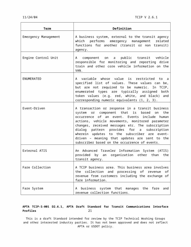
11/24/04 TCIP V 2.6.1
Term Definition
Subscription A relationship between an information consumer (subscriber) and an information provider (publisher) in which a contract (subscription) is established governing the information transfer. In TCIP there are three types of subscriptions – query, event, and periodic. These provide information on a one-time-basis, as-changed-basis, and recurring-interval-basis respectively.
Supervisor Portable or Vehicle (SPV) A component that allows a transit supervisor to exchange data with business systems and other transit components and systems. This component is an element of the TCIP physical architecture and a logical entity within TCIP.
TCIP Transit Communications Interface Profiles.
TCP Transmission Control Protocol
TCP/IP Transmission Control Protocol/Internet Protocol
TEI Transit Employee Interface – a device that allows a transit employee to interact with agency data networks. An example is a handheld wireless device used by a supervisor to enter an incident report.
Termini The “terminating” or end nodes of a line, link, or route.
Text Take A segment of text intended to be selected from a list of similar text takes to be inserted into a larger text message. For example a list of text takes representing bus stop names, would be used as the source for the bus stop name to be inserted into a bus stop arrival announcement (“Now approaching Broad Street Station”)
TFTP Trivial File Transfer Protocol
Timepoint A point along a public transit vehicle’s route where the vehicles scheduled time to transit that point is identified in the schedule.
TMC Traffic Management Center
TMDD Traffic Management Data Dictionary. A standard promulgated by ITE/AASHTO as standard number TMI.03.
TMV Transit Maintenance Vehicle
TMV-COM Transit maintenance portable or vehicle Communications manager entity
TMV-DAT Transit maintenance portable or vehicle Data manager entity
TMV-ECU Transit maintenance portable or vehicle Engine and drive train monitoring entity
APTA TCIP-S-001 D2.6.1, APTA Draft Standard for Transit Communications Interface Profiles 23
This is a draft Standard intended for review by the TCIP Technical Working Groups and other interested industry parties. It has not been approved and does not reflect APTA or USDOT policy.

11/24/04 TCIP V 2.6.1
Term Definition
TMV-EMT Transit maintenance portable or vehicle TSP emitter entity
TMV-HEL Transit maintenance portable or vehicle Health monitor entity
TMV-LDS Transit maintenance portable or vehicle Location sensor entity
TMV-LOC Transit maintenance portable or vehicle Location monitor entity
TMV-OPR Transit maintenance portable or vehicle operator interface entities
TMV-PRI Transit maintenance portable or vehicle TSP manager entity
TMV-SEC Transit maintenance portable or vehicle Security manager entity
Traffic Management An external (to transit) business system responsible for monitoring, facilitating, and reporting on the flow of traffic.
Transfer 1. A location where two or more transit routes provide service to the same or very closely located stop points, allowing passengers to conveniently switch between service provided on the various routes. 2. An event in a passenger’s trip itinerary wherein the passenger must alight from one PTV and board another to switch from service on one route to service on another route. 3. Move data between business systems and/or logical entities.
Transit Maintenance Vehicle A vehicle used by the transit maintenance function-usually to repair, tow etc, public transit vehicles outside of the garage. The vehicle may have an associated computer component which allows the vehicle to exchange data with other transit components and systems. This component is an element of the TCIP physical architecture and a logical entity within TCIP.
Transit Parking A transit owned or operated parking lot, and the associated components that monitor and report on the lot’s status.
Transit Security A business system responsible for managing transit security related resources, and incidents.
Transit Signal Priority A TCIP business area related to obtaining preferential treatment for PTVs at signalized intersections.
Traveler Information System A business system that provides information directly to transit travelers via a variety of communications media.
Trigger 1. The initiation of a series of actions (as of a dialog). 2. The event that initiates a series of actions.
APTA TCIP-S-001 D2.6.1, APTA Draft Standard for Transit Communications Interface Profiles 24
This is a draft Standard intended for review by the TCIP Technical Working Groups and other interested industry parties. It has not been approved and does not reflect APTA or USDOT policy.

11/24/04 TCIP V 2.6.1
Term Definition
Trip 1. A specified series of movements of a transit vehicle between an origin and a destination end point. Trips in revenue service normally involve passing through defined timepoints and providing service at stop points. 2. A single scheduled instance of a PTV providing service on a route in a designated direction. 3. A journey planned or undertaken by a transit customer, or a portion of such a journey.
TRV See Traveler Information System
TS Transit Security
TSP See Transit Signal Priority.
TSP Emitter A component on a public transit vehicle that sends signal priority requests directly to a receiver at an equipped intersection (e.g. infrared or optical emitter).
UDP User Datagram Protocol
UDP/IP User Datagram Protocol/Internet Protocol
Unbound A state of a vehicle or operator work assignment in which the work defined by the assignment has not been associated with the specific vehicle or operator expected to perform the assignment.
Unload Remove a large data message or messages from a vehicle or field device to a fixed business system.
URI Universal Resource Identifier
URL Universal Resource Locator
UTC Universal Time Coordinated – See Coordinated Universal Time
UTF8String A variable capable of conveying a series of characters, numbers, and special characters. This data type is capable of conveying special character sets, although this is not recommended for TCIP. Refer to ISO 8824-1.
VAN Vehicle Area Network. A data communications network within PTV, usually conforming to SAE J1708/J1587, or SAE J1939/J1587.
Vehicle Logic Unit (VLU) A computer on a transit vehicle that coordinates a variety of operational functions usually including Automatic Vehicle Location and messaging.
Version A particular instance of an artifact. Usually applied to artifacts that are released on a recurring basis. May be identified by version numbers and/or effective date.
APTA TCIP-S-001 D2.6.1, APTA Draft Standard for Transit Communications Interface Profiles 25
This is a draft Standard intended for review by the TCIP Technical Working Groups and other interested industry parties. It has not been approved and does not reflect APTA or USDOT policy.

11/24/04 TCIP V 2.6.1
Term Definition
VIN Vehicle Identification Number
VLU Vehicle Logic Unit
W3C The World Wide Web Consortium (W3C) develops interoperable technologies (specifications, guidelines, software, and tools) to lead the Web to its full potential. W3C is a forum for information, commerce, communication, and collective understanding.
WAN Wide Area Network
WLAN Wireless Local Area Network
XML Extensible Markup Language. W3C (Which defines Internet standards) defines XML as the “universal format for structured documents and data on the web”.
XML Schema Defines the structure of XML documents (or messages in TCIP) W3C states “XML schemas express shared vocabularies and allow machines to carry out rules made by people. They provide a means for defining the content and semantics of XML documents”.
XPATH XML Path Language
XQUERY XML Query
XSD XML Schema Definition – a file type used to hold XML Schema files.
APTA TCIP-S-001 D2.6.1, APTA Draft Standard for Transit Communications Interface Profiles 26
This is a draft Standard intended for review by the TCIP Technical Working Groups and other interested industry parties. It has not been approved and does not reflect APTA or USDOT policy.

11/24/04 TCIP V 2.6.1
3. TCIP Data
TCIP data is defined in a three-tiered manner. Data elements are single pieces of data such as time of day, speed, vehicle identifier, or route id. Data frames are groupings of data elements (and/or other data frames) into larger abstractions necessary to describe more complex items. Messages are similar to data frames in that they are aggregates of data elements and data frames into a larger and more complex structure, however, messages are intended to constitute a complete understandable one-way communication rather than being a constituent of a larger object.
To make TCIP data easier to understand, naming conventions have been adopted for TCIP Data Elements, Data Frames, and Messages. Data Elements are identified by a Business Area Name in all capital letters, followed by a hyphen, followed by the name of the data, for example, CPT-EmployeeFirstName. Data Frames are identified by a Business Area Name in all capital letters, with no hyphen, followed by the name of the data, for example, SCHPatternInfo. Messages are identified by a Business Area Name with an initial capital letter, followed by the name of the data, for example, PiNearestStopListSub.
In some cases, TCIP imports data frame or data element definitions from other standards such as SAE J2266 Location Referencing Message Specification (LRMS). In these cases, the ASN.1 usage is to identify the data element or data frame using a dot notation with the source specification to the left of the period in capital letters and the name as defined in the source specification to the right. For example, LRMS.GeoLocation. In the XML schema, the equivalent usage is a colon notation with the source name in lower case, for example, lrms:GeoLocation.
TCIP data was originally specified using Abstract Syntax Notation One (ASN.1). The data element, data frame, and message definitions in this document (Annexes A, B and C) include normative specifications, rules, and constraints for the data in English. These definitions also include normative ASN.1-style descriptions of the content of each item. TCIP data is intended to be conveyed in Extended Markup Language (XML) format, an agency defined narrowband format or in TCIP narrowband encoded format (see section 6.2). Conformance requirements for TCIP are defined in Section 8.
Commentary: SAE J2630 reference [I-10] was used as a guideline when converting from ASN.1 to XML.
Some TCIP dialogs and file transfers need to be implemented over limited bandwidth network connections. Because XML is a verbose data representation, it is not viable over some of these narrow band links. A variety of more succinct encoding schemes are available for sending TCIP messages over narrowband links including ASN.1 packed encoding rules, a zip file containing an XML message, and a TCIP-defined narrowband encoding scheme. Any agency-approved succinct encoding scheme is considered conformant provided that the complete message as defined in ASN.1 is preserved without information loss or corruption. Lossy compression schemes, such as the types often used with images and audio files, are considered non conformant. Section 6.2 defines an optional narrowband TCIP message encoding scheme for TCIP message for use in narrowband networks.
APTA TCIP-S-001 D2.6.1, APTA Draft Standard for Transit Communications Interface Profiles 27
This is a draft Standard intended for review by the TCIP Technical Working Groups and other interested industry parties. It has not been approved and does not reflect APTA or USDOT policy.

11/24/04 TCIP V 2.6.1
3.1 Data Elements
TCIP data elements are based on the ASN.1 data types. These base ASN.1 types have been extended to create additional generic data types for use in creating TCIP data elements. The definitions for the base types for TCIP data element definitions are found in Annex H.
TCIP numbers the defined data elements within each business area. Data elements defined in the original standards are identified by the business area abbreviation (e.g. CPT, SCH) and a number.
TCIP data elements are based on the ASN.1 types and the TCIP subtypes defined in Annex H. For example NAME30 is derived from UTF8String as NAME30::=UTF8String (size(1…30)). TCIP defines data elements based on the NAME30 subtype, as in the definition of cptdd 18
CPT-EmployeeFirstName::=NAME30.
Finally the data element definition is used to create an XML Schema. The corresponding schema entry for this element is
<xsd:simpleType name="CPT-EmployeeFirstName" ><xsd:restriction base ="NAME30"/></xsd:simpleType>
APTA TCIP-S-001 D2.6.1, APTA Draft Standard for Transit Communications Interface Profiles 28
This is a draft Standard intended for review by the TCIP Technical Working Groups and other interested industry parties. It has not been approved and does not reflect APTA or USDOT policy.

11/24/04 TCIP V 2.6.1
3.2 TCIP Data Frames
Data frames are groupings of data elements (and/or other data frames) into abstractions necessary to describe more complex items. For instance a data frame describing an employee might include name, employee number, and date of employment and/or other information. Depending on the context, the description of an employee might require more or less information. As an example, the employee's date of hire might be important to a personnel action, but not relevant to an assignment as an operator for a particular bus run. Consequently similar data frames may be created for use in different contexts, and/or data frames may be created with optional data fields that can be used in some contexts and not others. In some cases two optional fields may be incompatible, requiring explanatory material in the data frame usage area.
Figure 3.2 illustrates the definition of data frames in TCIP.
APTA TCIP-S-001 D2.6.1, APTA Draft Standard for Transit Communications Interface Profiles 29
This is a draft Standard intended for review by the TCIP Technical Working Groups and other interested industry parties. It has not been approved and does not reflect APTA or USDOT policy.

11/24/04 TCIP V 2.6.1
Example Data Frame Definition in ASN.1
IncludedData Frame
IncludedData
Elements
Example Data Frame Definition in XML
SCHPatternInfo::=SEQUENCE {patternID SCH-PatternID,pattern-designator SCH-PatternDesignator OPTIONAL,pattern-name SCH-PatternName OPTIONAL,pattern-notes SEQUENCE (SIZE(1..100)) OF SCH-NoteID OPTIONAL,triggers SEQUENCE (SIZE(1..200)) OF SCH-ActivationID OPTIONAL,mode CPT-Mode OPTIONAL,segments SEQUENCE (SIZE(1..100)) OF SCH-PatternSegmentID,radio-zones SEQUENCE (SIZE(1..100)) OF CPTRadioZone OPTIONAL}
<xs:complexType name="SCHPatternInfo" > <xs:sequence> <xs:element name="pattern-designator" type="SCH-PatternDesignator" minOccurs="0"/> <xs:element name="pattern-name" type="SCH-PatternName" minOccurs="0"/> <xs:element name="pattern-notes" minOccurs="0"> <xs:complexType> <xs:sequence minOccurs="1" maxOccurs="100"> <xs:element name="pattern-note" type="SCH-NoteID" /> </xs:sequence> </xs:complexType> </xs:element> <xs:element name="triggers" minOccurs="0"> <xs:complexType> <xs:sequence minOccurs="1" maxOccurs="200"> <xs:element name="trigger" type="SCH-ActivationID" /> </xs:sequence> </xs:complexType> </xs:element> <xs:element name="mode" type="CPT-Mode" minOccurs="0"/> <xs:element name="segments" > <xs:complexType> <xs:sequence minOccurs="1" maxOccurs="100"> <xs:element name="segment" type="SCH-PatternSegmentID" /> </xs:sequence> </xs:complexType> </xs:element> <xs:element name="radio-zones" minOccurs="0"> <xs:complexType> <xs:sequence minOccurs="1" maxOccurs="100"> <xs:element name="radio-zone" type="CPTRadioZone" /> </xs:sequence> </xs:complexType> </xs:element> </xs:sequence></xs:complexType>
Figure 3.2
APTA TCIP-S-001 D2.6.1, APTA Draft Standard for Transit Communications Interface Profiles 30
This is a draft Standard intended for review by the TCIP Technical Working Groups and other interested industry parties. It has not been approved and does not reflect APTA or USDOT policy.

11/24/04 TCIP V 2.6.1
3.3 TCIP Messages
Messages are aggregates of data elements and data frames into a larger and more complex structure. Messages are intended to constitute a complete understandable one-way communication. Messages are not intended to be aggregated into larger data objects for communications. Individual message definitions are used as the basis of TCIP file transfers. A sequence of one or more messages are used in the definition of each TCIP dialog. These sequences create complete conversations between entities providing two (or more) way communications. TCIP messages are identified by business area abbreviation and a number 2000 or higher. Figure 3.3 illustrates the definition of TCIP messages.
TCIP Message Definition in ASN.1
PiNearestStopListSub ::= SEQUENCE{subscriptionInfo CPTSubscriptionHeader,request PiNearestStopRequest,includeDistance PI-Distance OPTIONAL}
IncludedData
Elements
IncludedData
Frames
TCIP Message Definition in XML
<xsd:complexType name="PiNearestStopListSub" > <xsd:sequence> <xsd:element name="subscriptionInfo" type="CptSubscriptionHeader" /> <xsd:element name="request" type="PiNearestStopRequest" /> <xsd:element name="includeDistance" type="PI-Distance"minOccurs="0"/> </xsd:sequence></xsd:complexType>
Figure 3.3TCIP Message Definitions
APTA TCIP-S-001 D2.6.1, APTA Draft Standard for Transit Communications Interface Profiles 31
This is a draft Standard intended for review by the TCIP Technical Working Groups and other interested industry parties. It has not been approved and does not reflect APTA or USDOT policy.
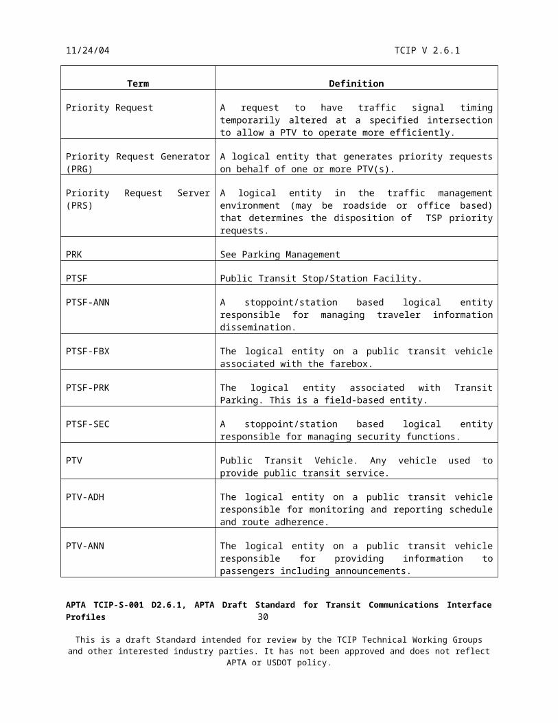
11/24/04 TCIP V 2.6.1
4. Understanding TCIP
TCIP standardizes information exchanges among transit business systems and components, either on a batch (file transfer), or automated (message exchange) basis. By standardizing and modularizing these interfaces, the intent is to minimize the cost of tailoring interfaces. These costs occur as a result of vendor changes to interfaces for an individual agency, or another supplier. By standardizing these interfaces, different agencies and vendors will be able to reuse the same interfaces. By modularizing these interfaces, each agency will be able to select the specific interactions across the interfaces (dialogs and file transfers) necessary to meet their specific business needs.
The mechanism for conveying an agency’s TCIP requirements to a supplier is a Profile Implementation Conformance Statement (PICS). The agency creates a PICS as part of their specification for a new or upgraded system. The PICS defines the dialogs, message transfers, and options associated with the new system. The supplier provides a PICS describing their product as part of the proposal submittal. Comparison of agency PICS requirements with supplier PICS claims of compliance allows an agency to determine if the offered TCIP implemented interface will meet the agency’s requirements.
APTA TCIP-S-001 D2.6.1, APTA Draft Standard for Transit Communications Interface Profiles 32
This is a draft Standard intended for review by the TCIP Technical Working Groups and other interested industry parties. It has not been approved and does not reflect APTA or USDOT policy.

11/24/04 TCIP V 2.6.1
4.1 Structure of TCIP
TCIP defines the messages, data frames, and data elements to be used for information transfers. For automated interfaces, TCIP defines the sequence of interactions between the interfaced systems in the form of dialogs. TCIP implementations are modular so that each agency can choose the specific standard messages to be exchanged using dialogs or file transfers to meet that agency's needs. These decisions should be documented in the agency’s architecture along with network and protocol definitions and other information allowing them to serve as a baseline and a starting point for RFP development. Figure 4.1 depicts the building block approach to TCIP.
The lowest level objects in TCIP are dialog patterns and data elements. Dialog patterns define a type of exchange in generic form, such as the sequence of actions in a query or a command-response. Data elements define the lowest level data objects in TCIP and how they are represented. For example a data element CPT-EmployeeFirstName is defined as having type NAME30, which is in turn defined to be a string of up to 30 characters.
TCIP data frames build on TCIP data elements by grouping data elements together to describe something meaningful in the real world. For example an employee description might include other items besides first name such as middle and last name, phone number, employee number and address.
TCIP messages build on TCIP data elements and data frames, incorporating them into a meaningful one-way information transfer package. For example, a message defining an incident might incorporate information concerning the employee reporting the incident, vehicles involved, people injured, and incorporate as many data elements and data frames as are required to create a complete one-way information transfer.
TCIP dialogs build on the dialog patterns which define the structure of the interaction (such as a query) and the messages which define the content of the interaction (the information to be exchanged). TCIP file transfer builds on the messages, but not the dialog patterns, because these file transfer mechanisms are defined by vendors and agencies, and documented in the PICS (see section 8).
The agency architecture builds on the agency’s legacy systems, and on TCIP file transfers and dialogs. The agency architecture also needs to consider how the agency fits into the regional architecture, and how the agency and other regional stakeholders plan to evolve their business systems over time. Agency architectures may, but are not required to, build on the TCIP Model Architecture.
APTA TCIP-S-001 D2.6.1, APTA Draft Standard for Transit Communications Interface Profiles 33
This is a draft Standard intended for review by the TCIP Technical Working Groups and other interested industry parties. It has not been approved and does not reflect APTA or USDOT policy.

11/24/04 TCIP V 2.6.1
Data Elements
Dialog-based Message TransfersMessage File-basedMessage Transfers
Dialogs
Dialog PatternsMessages
Data Frames
Data Frames
Figure 4.1Relationships among TCIP Components
LegendA
B
A is used todefine B
APTA TCIP-S-001 D2.6.1, APTA Draft Standard for Transit Communications Interface Profiles 34
This is a draft Standard intended for review by the TCIP Technical Working Groups and other interested industry parties. It has not been approved and does not reflect APTA or USDOT policy.

11/24/04 TCIP V 2.6.1
4.2 TCIP Model Architecture
4.2.1 Overview
The TCIP model architecture identifies key transit agency elements pertinent to TCIP and their interfaces. It also provides a useful structure for illustrating the building block approach to interface development provided by the TCIP dialogs and file transfers. The model architecture is not intended to represent the actual configuration of any transit agency, nor is it intended to recommend any specific approach to agency or regional architecture development. The sole purpose of the Model Architecture is to provide a conceptual basis for the discussion of agency business processes and interfaces.
The components of the Model Architecture are: Logical Entities – which perform a group of related functions (e.g. PTV-LOC) Physical Components – elements in the physical architecture (e.g. farebox) Business Systems – fixed computer applications and systems used by an agency to manage or facilitate
business processes. Business Systems are elements in both the physical and logical views of the Model Architecture.
Interfaces to agency equipment (e.g. vehicle, stoppoint, sensors etc.) External Systems Communications Networks
The top-level TCIP Physical Model Architecture is shown in figure 4.2.1.
The Model Architecture assumes a one-to-one mapping between physical and logical entities within business systems. This is a convenient view for describing a generic agency, however, real agencies may have differently named business systems organized very differently than the Model Architecture arrangement. Such agency architectures are still able to adopt TCIP dialogs and file transfers to exchange information among business systems. The internal architecture of a business system is not addressed by TCIP or by the Model Architecture.
Agency unique business systems may include planning systems, joint agency-local government shared systems, agency developed systems (e.g. financial, analysis, personnel management), project management tools, off the shelf tools for network modeling, operations research packages. Off the shelf applications may be modified or extended by agency IT departments. Agencies may have unique or proprietary systems for developing the CcStopAndDestInfo file containing announcements for stoppoints, destination sign controls, and event-triggered onboard announcements.
TCIP enabled business systems communicate with each other either: Via file/document transfers which may be conducted through the transit agency data network, or Via physical file/document transfers using removable media, or Via dialogs which define message-based conversations between business systems via the transit
agency data network.
Some agency architectures include a data repository – usually a large database, or group of databases. In such agencies, the repository serves as an intermediary in these conversations between business systems. This allows a business system to produce or consume information asynchronously from other business systems, eliminates the need for an information producing system to communicate with all of the information consumers, and provides a platform for fusing data from multiple sources. Data repositories generally require technically sophisticated staff to set up and administer, and consequently are not found in many smaller agencies.
Transit agencies operate a variety of field systems, components, and devices. These may be monitored, controlled, or both. Field equipment includes fare media vending equipment, elevators, escalators, door alarms, passenger information displays, vent fans, and a wide variety of other device types. TCIP provides a limited set of dialogs
APTA TCIP-S-001 D2.6.1, APTA Draft Standard for Transit Communications Interface Profiles 35
This is a draft Standard intended for review by the TCIP Technical Working Groups and other interested industry parties. It has not been approved and does not reflect APTA or USDOT policy.
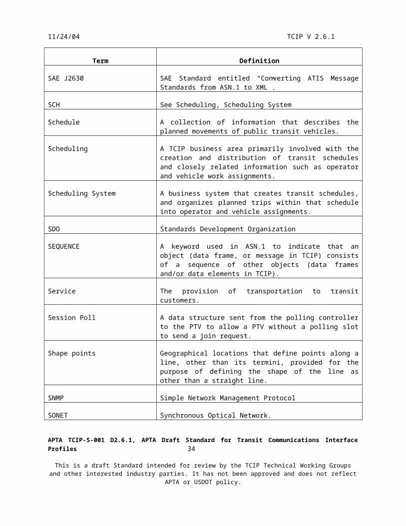
11/24/04 TCIP V 2.6.1
for communicating with logical entities that act as controllers or managers of these devices. The Model Architecture identifies these field device controller/manager entities, but does not specify their physical configuration. These logical entities may be packaged with the field device or may be packaged separately in a unit that controls/manages a group of devices (e.g. for a passenger station). Other agency-specified standards and/or proprietary protocols are used to interact with field devices in parallel with TCIP.
Public Transit Vehicles (PTVs) contain a variety of logical functions that are packaged very differently from one agency (or even one bus type within an agency) to another. The Model Architecture identifies these logical entities, and identifies some, but not all, possible physical configurations of these entities. TCIP provides dialogs for communications between PTV logical entities and fixed business systems, and dialogs for some communications between onboard logical entities which are likely to be separately packaged. TCIP recognizes that a significant component of the communications within PTVs occur using non-TCIP data exchanges via the Vehicle Area Network (VAN). VAN communications are defined in the SAE J-1587, J-1708, and J-1939 standards. The Model Architecture assumes that TCIP messages between onboard components are not exchanged on the VAN, but are conveyed over a separate onboard IP/Ethernet-based network referred to as the “Hub”.
Transit business systems also communicate with entities outside of the transit agency itself. These include external Advanced Traveler Information Systems (ATIS), Traffic Management Systems, Information Service Providers, other transit agencies, public safety agencies, traveler-owned Internet appliances, and other systems. These conversations are generally governed by standards promulgated by other industries; however TCIP dialogs do include support for Transit Signal Priority interactions with Traffic Management Systems consistent with NTCIP 1211.
In parallel with the development of TCIP, an effort has been underway to develop a National ITS Architecture (NIA). Since these efforts were conducted independently, there is an imperfect match between TCIP and the NIA. Nonetheless, there is substantial interest in a mapping between NIA and TCIP. Such a rough mapping is contained in Annex I “TCIP-NIA Mapping”. This Annex maps TCIP logical entities to the closest match NIA ‘Pspec’ and TCIP Dialogs to the closest match NIA data flows. Note that NIA data flows are unidirectional, and dialogs are bi- or multi-directional so dialogs generally map to more than one data flow.
APTA TCIP-S-001 D2.6.1, APTA Draft Standard for Transit Communications Interface Profiles 36
This is a draft Standard intended for review by the TCIP Technical Working Groups and other interested industry parties. It has not been approved and does not reflect APTA or USDOT policy.

11/24/04 TCIP V 2.6.1
Figure 4.2.1Top Level Physical TCIP Model Architecture
APTA TCIP-S-001 D2.6.1, APTA Draft Standard for Transit Communications Interface Profiles 37
This is a draft Standard intended for review by the TCIP Technical Working Groups and other interested industry parties. It has not been approved and does not reflect APTA or USDOT policy.

11/24/04 TCIP V 2.6.1
Internet, Extranet, or Other Fixed Point to Fixed Point Communications
Wide Area (Mobile)Communications
Wire
less
LA
N
Agency Fixed Point to Fixed Point Communications
CAD/AVL
InformationServiceProvider
(ISP)
OtherAgencies
EmergencyMgmt
Traffic MgmtCenter
Public SafetyCAD
ExternalATIS
Banks Local Gov'ts
GarageRevenueSystem(GRS)
PassengerCounting
(PC)
AuthorizedBusinessSystem(ABS)
ParkingMgmt(PRK)
CustomerServiceSystem(CSS)
TravelerInformation
System(TRV)
Fare System(FS)
DataRepository
(DR)
GeographicalInformation
Systems(GIS)
Scheduling(SCH)
TransitSecurity
(TS)
AuthorizedBusinessSystem(ABS)
HumanResources
(HR)
GarageServer(GS)
NetworkMgmt(NM)
Asset Mgmt(AM)
AuthorizedBusinessSystem(ABS)
OperatorAssignment
System(OAS)
TransitParking
(PTSF-PRK)
TravelerInformation
(PTSF-ANN)
FareCollection
(PTSF-FBX)
SecurityMonitoring
(PTSF-SEC)
TransitMaintenance
Vehicle(TMV)
SupervisorPortable or
Vehicle(SPV)
PublicTransitVehicle(PTV)
PersonalInformation
Access
RemoteTravelerSupport
External Business Systems
Transit Business Systems
Mobiles/Portable Agency Environment
Travelers
Transit Field Environment
TCIP Model Architecture
Payroll(PAY)
Non TransitField Environment
RoadsidePriority
RequestServer
RegionalRevenueClearingHouse
APTA TCIP-S-001 D2.6.1, APTA Draft Standard for Transit Communications Interface Profiles 38
This is a draft Standard intended for review by the TCIP Technical Working Groups and other interested industry parties. It has not been approved and does not reflect APTA or USDOT policy.
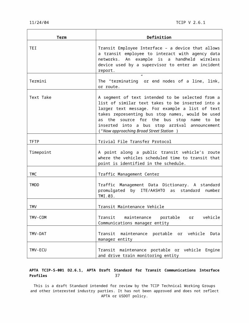
11/24/04 TCIP V 2.6.1
4.2.2 Business Systems
Transit business systems may be developed by the agencies themselves or by commercial providers. Generally, commercial systems are tailored to some extent for each agency, and agency-developed systems tend to be highly customized. This implies that there may be significant differences in functionality and operation from one agency to another. Furthermore, different agencies and vendors package functionality into business systems with different names and groupings. Thus the model architecture and associated assignments of functions to business systems in this model is neither normative, nor definitive.
TCIP assumes that business systems maintain logs of events and transactions and provide archiving and retrieval capabilities which may be compliant with the National ITS Architecture Archive User Data Service (ADUS). TCIP does not standardize the logging functions of business systems, but does provide some limited functionality for transferring logged information in a standardized format.
Table 4.2.2 summarizes the business systems illustrated in figure 4.2.1, lists their major functions and typical agency architectural variations.
Table 4.2.2
Transit Agency Business Systems
Name Typical Functions/Contents Typical Variations
Authorized Business System (ABS) May be agency designated to
participate as a business system in any dialog or file transfer.
Agencies may define any number of ABS for any functions as they see fit. Examples may include planning systems, back office reporting systems and functions described in model architecture business systems which are organized differently in the agency architecture.
CAD/AVL System (CAD) Track PTVs Provide Dispatcher Interface Provide PTV Adherence
Monitoring Interface Provide Alarm Management Manage Exceptions to Operating
Plan Manage Incidents Provide Operating Status
Information to other Business Systems
This may be designed and/or purchased as separate CAD and AVL systems; however, TCIP does not specify dialogs between the CAD and AVL components.
APTA TCIP-S-001 D2.6.1, APTA Draft Standard for Transit Communications Interface Profiles 39
This is a draft Standard intended for review by the TCIP Technical Working Groups and other interested industry parties. It has not been approved and does not reflect APTA or USDOT policy.

11/24/04 TCIP V 2.6.1
Table 4.2.2
Transit Agency Business Systems
Name Typical Functions/Contents Typical Variations
Customer Service (CSS) Complaint investigation
o Completed trip historyo Playback of PTV
operations Itinerary creation Parking information Call taking Demand (paratransit) trip booking Customer eligibility (e.g. senior,
paratransit)
Customer Service System and Traveler Information System may be combined.
Data Repository (DR) PTV Data Load/Unload Transit Facilities Information
Store Personnel Data Store Schedule Data Store Software & Configuration Data
Store Historical Operating Data Store
Data Repository may not be present, & data stores distributed among other Business Systems
DR interactions with PTVs (loads/unloads) may be performed by a Garage Server.
Fare System (FS) Manage fare zones/fare tables, etc. Fare data and nightly reconciliation
with PTVs/Fare vending machines Bank reconciliation Fare type/count/location Tracking
& Reporting Bad card list Card issuance management
Some or all functions may be performed by regional reconciliation system
Some functions may be contracted out to a commercial services provider
Operator Assignment System
(OAS)
Manage pull-outs/pull-ins Manage fitness for service checks
(operators) Bind available operators to planned
trips/runs Operator ‘Pick’ management Rostering (with a-la-carte style
pick) Generate ‘extra list’ Manage last minute changes to
operator and vehicle assignments
May be combined with Maintenance Management
APTA TCIP-S-001 D2.6.1, APTA Draft Standard for Transit Communications Interface Profiles 40
This is a draft Standard intended for review by the TCIP Technical Working Groups and other interested industry parties. It has not been approved and does not reflect APTA or USDOT policy.

11/24/04 TCIP V 2.6.1
Table 4.2.2
Transit Agency Business Systems
Name Typical Functions/Contents Typical Variations
Geographical Information System (GIS)
Transit Facilities Information Transit Route/Pattern Information Stoppoint inventory Fare zone geometry Ridership history by location Area maps Jurisdictional boundaries
GIS may be provided by local or regional government.
Asset Management System (AM) Track all past performed
maintenance events Forecast and plan scheduled
maintenance Forecast and plan vehicle car
availability Track vehicle car work orders Track/forecast component
subsystem performance/reliability Track/forecast spare parts
requirements and requisitions Manage PTV garage area parking Bind available vehicles to planned
trips/blocks
May be combined with Garage Operations.
Parking Management (PRK) Transit Agency Operated Parking
Garage Management System
Payroll (PAY) Payroll calculations
Scheduling
(SCH)
Create Scheduleo Define Patternso Define Tripso Define Timepointso Define Transfers
Blocking/Runcuttingo Define Operator
Assignments (unbound)o Define Vehicle
Assignments (unbound)o Rostering agencies
without a-la-carte picks Reporting (various output data
filters and organizations)
Timepoints and/or stoppoints may be defined in scheduling system, GIS, data repository, or other agency-specified tool.
APTA TCIP-S-001 D2.6.1, APTA Draft Standard for Transit Communications Interface Profiles 41
This is a draft Standard intended for review by the TCIP Technical Working Groups and other interested industry parties. It has not been approved and does not reflect APTA or USDOT policy.

11/24/04 TCIP V 2.6.1
Table 4.2.2
Transit Agency Business Systems
Name Typical Functions/Contents Typical Variations
Traveler Information System (TRV) Itinerary creation Parking information Fare information (for planned trip) Next Bus information
o Timetable o ETA
Passenger Information Display (PID) monitoring & control Interface to ATIS Systems Interface to 511 Systems
Traveler Information System and Customer Service System may be combined.
Garage Revenue System
(GRS)
Mange collection of cash and data from PTV’s and PTSF-based fare components Provide vault information to Fare System
May be combined with fare system.
Transit Security (TS) Manage Transit Security Sensors (cameras, alarms, etc.) Facilitate, monitor and control access to CCTV images Manage alarms Incident Management
Garage Server (GS) Manage loading of data to PTV’s Mange unloading of data from PTV’s Provide logging and reporting functions
May be combined with Data Repository.
Passenger Counting (PC) Collect passenger count data from PTV’s PTSF equipment and other sources. Distributes passenger count data to other business systems.
May be combined with Data Repository.
4.2.3 Public Transit Vehicles
Public Transit Vehicles (PTVs) exhibit differing physical architectures from one agency to another, and in many cases between vehicle types or brands within an agency. PTV logical entities perform various business activities onboard the PTV. PTV-HEL, for example, monitors and reports the health of the vehicle, and the subsystems onboard the vehicle. Logical entities on a PTV may communicate with each other and/or with fixed business systems as they carry out their functions. These communications may be TCIP-based via the hub (onboard). They may be TCIP based to fixed business systems via a radio, public network, or wireless LAN. They may include non-TCIP communications via the VAN or via other networks as well.
The PTV Model Architecture is shown in Figure 4.2.3A&B. Figure 4.2.3.A depicts a PTV with its logical entities highly distributed into separate physical components. The Model Architecture assumes that the 5 logical entities shown in the Vehicle Logic Unit are ‘core’ to that component and are not distributed. Figure 4.2.3.B depicts a
APTA TCIP-S-001 D2.6.1, APTA Draft Standard for Transit Communications Interface Profiles 42
This is a draft Standard intended for review by the TCIP Technical Working Groups and other interested industry parties. It has not been approved and does not reflect APTA or USDOT policy.

11/24/04 TCIP V 2.6.1
PTV with a highly integrated package where more logical entities are consolidated into the Vehicle Logic Unit. These figures are intended to illustrate the range of alternatives available, not to represent all possible permutations of the PTV physical architecture.
Note that optional discrete connections are shown for operator alarm, covert (silent) alarm, and passenger alarms. These trigger corresponding security-related dialogs.
The farebox optionally incorporates a card reader. This may be a smart card reader, magnetic card reader, paper ticket reader, or other type of portable media reader. This device may also write or act as a vending machine for media depending on the local agency architecture. The device may also be used as the mechanism for PTV operator logins.
APTA TCIP-S-001 D2.6.1, APTA Draft Standard for Transit Communications Interface Profiles 43
This is a draft Standard intended for review by the TCIP Technical Working Groups and other interested industry parties. It has not been approved and does not reflect APTA or USDOT policy.

11/24/04 TCIP V 2.6.1
Engine Control Unit PTV-ECU
Wireless LAN
Other Onboardcomponent
PTV-OTH
Farebox PTV-FBX
Vehicle Logic Unit
PTV-ADH PTV-COM PTV-DAT PTV-HEL PTV-LOC
Location Data Source PTV-LDSH
UB
VA
N
Odometer*Back-up Lights*
Ignition
DataRadio
VoiceRadio
TSP Emitter PTV-EMT
Transit Signal PrioritySystem
PTV-PRI
Passenger CountingSystem
PTV-PAS
Annunciator PTV-ANN
Security System PTV-SEC
Mobile Data Terminal PTV-OPR
Covert Alarm
Passenger Alarm
Destination Signs
Passenger Info Signs
Passenger Counter
Wheelchair Lift
Door Sensors
Transmission
Odometer*
Engine
Brakes
Other Drive Train Elements
Back Up Lights*
CCTVCameras
Speakers
Public Transit Vehicle
Legend: Bulleted items represent Model Architecture
Logical Entities Bulleted green Italic items represent logical
entities which may be packaged separately fromthe VLU or with the VLU
Voice Radio & Data may be combined Hub, Wireless LAN, and Data Radio messages
defined by TCIP Hub and wireless LAN communications use XML,
and either TCP/IP or UDP/IP communications. VAN messages defined by SAE J1587, J1708
and/or J1939 * May be read via VAN or discrete connection
Figure 4.2.3.APTV Model Architecture with Logical Entities Distributed
Operator Alarm
Card Reader
APTA TCIP-S-001 D2.6.1, APTA Draft Standard for Transit Communications Interface Profiles 44
This is a draft Standard intended for review by the TCIP Technical Working Groups and other interested industry parties. It has not been approved and does not reflect APTA or USDOT policy.

11/24/04 TCIP V 2.6.1
Vehicle Logic Unit
PTV-ADH PTV-COM PTV-DAT PTV-HEL PTV-LOC PTV-OPR PTV-SEC PTV-ANN PTV-PAS PTV-PRI PTV-LDS
Odometer*Back-up Lights*
Ignition
DataRadio
VoiceRadio
Destination Signs
Passenger Info Signs
Speakers
CCTV Camera
Engine Control Unit PTV-ECU
Other Onboardcomponent
PTV-OTH
Farebox PTV-FBX
TSP Emitter PTV-EMT
Transmission
Odometer*
Engine
Brakes
Other Drive Train Elements
Back Up Lights*
Figure 4.2.3.BPTV Model Architecture with Logical Entities Consolidated in VLU
Public Transit Vehicle
Wireless LAN
VAN
HUB
Legend: Bulleted items represent Model Architecture
Logical Entities Bulleted green Italic items represent logical
entities which may be packaged separately fromthe VLU or with the VLU
Voice Radio & Data may be combined Hub, Wireless LAN, and Data Radio messages
defined by TCIP Hub and wireless LAN communications use XML,
and either TCP/IP or UDP/IP communications. VAN messages defined by SAE J1587, J1708
and/or J1939 * May be read via VAN or discrete connection
Operator AlarmCovert Alarm
Passenger AlarmPassenger Counters
Wheelchair Lift
Door Sensors
Card Reader
Pre-TCIP PTV onboard communications are usually based on SAE J1708/J1587 standards. The newer, higher speed SAE J1939 standard may soon be in common use. In either case the network shown in blue in Figures 4.2.3.A&B convey SAE-standardized information. These standards are designed to allow arbitrary combination of compliant devices to co-exist on the VAN and to exchange information.
As information technology has progressed, more and more PTVs are being equipped to communicate via high-speed wireless local area networks (WLAN). WLAN communications typically uses the Internet Protocol (IP) at layer 3 with the potential to implement a variety of higher-level protocols as is done with office local area networks. This high-speed connection to the fixed side data networks can be shared by a variety of onboard PTV components using a hub. This hub allows various components to access the WLAN, but also enables hub-
APTA TCIP-S-001 D2.6.1, APTA Draft Standard for Transit Communications Interface Profiles 45
This is a draft Standard intended for review by the TCIP Technical Working Groups and other interested industry parties. It has not been approved and does not reflect APTA or USDOT policy.

11/24/04 TCIP V 2.6.1
connected components to communicate with each other using IP. TCIP onboard dialogs operate over the hub and IP communications infrastructure. Other non-TCIP IP-based communications may coexist with TCIP on the hub/IP network. This capability is represented by the red network in Figure 4.2.3.A&B
PTVs also have data communications with fixed business systems when outside of the Wireless LAN coverage area either through the transit agency’s private radio network, or through public networks provided by the common carriers (phone companies). These facilities are generally more expensive and/or capacity limited, and agencies generally avoid sending large data transfers via these mechanisms.
TCIP dialogs specify the conversations to be carried out between: Onboard hub-connected components using XML (red network) Onboard components communicating to fixed business systems via the Wireless LAN using XML Onboard components communicating to fixed business systems via the private or public data network,
these communications may use the TCIP narrowband encoding or another agency specified succinct transfer syntax.
TCIP dialogs do not specify the communications occurring on the VAN (blue network); however, the dialogs do note where related VAN communications occur within a dialog’s execution.
Table 4.2.3 summarizes the major communicating components on PTV along with their major functions and typical variations.
Table 4.2.3
PTV Logical & Physical Entities
Physical Component Name
(Logical Entity)
Typical Functions/Contents Typical Variations
Engine Control Unit
(PTV-ECU)
Monitor drivetrain and other vehicle parameters and distribute their values via VAN
APTA TCIP-S-001 D2.6.1, APTA Draft Standard for Transit Communications Interface Profiles 46
This is a draft Standard intended for review by the TCIP Technical Working Groups and other interested industry parties. It has not been approved and does not reflect APTA or USDOT policy.

11/24/04 TCIP V 2.6.1
Table 4.2.3
PTV Logical & Physical Entities
Physical Component Name
(Logical Entity)
Typical Functions/Contents Typical Variations
Farebox
(PTV-FBX)
Collect and record fares via various media
Report fare information to fare system for end-of-day reconciliation
Accept login from MDT or provide login to MDT
Provide passenger counts to other onboard entities based on fares collected
Reads and processes smartcards, tickets and/or other agency-specified fare media
Accept passenger counts from other onboard entities to validate number of fares collected.
Login exchanges are not available on all fareboxes
Passenger count information is not provided to the VLU by many fareboxes
Location Data Source (NIA Entity) (PTV-LDS)
Onboard PTV sensor that provides location to vehicle (PTVLOC).
May be packaged with the VLU or separately. May be connected via VAN, or plug into VLU.
Mobile Data Terminal
(PTV-OPR)
Provide operator logon/logoff with notification to business systems
Provide relief operator sign on with notification to other entities
Provide two-way operator –dispatcher canned message and text message exchange
Provide operator logon/logoff notification to other onboard components
Provide input/output screen capability for other onboard devices
May be combined with the Vehicle Logic Unit.
TSP Emitter
(PTV-EMT)
Onboard PTV emitter that conveys transit signal priority requests to suitably equipped intersections.
May be optical (light) based, infrared based, transponder based, etc.
APTA TCIP-S-001 D2.6.1, APTA Draft Standard for Transit Communications Interface Profiles 47
This is a draft Standard intended for review by the TCIP Technical Working Groups and other interested industry parties. It has not been approved and does not reflect APTA or USDOT policy.
11/24/04 TCIP V 2.6.1
Table 4.2.3
PTV Logical & Physical Entities
Physical Component Name
(Logical Entity)
Typical Functions/Contents Typical Variations
VLU Communications Manager
(PTV-COM)
This entity controls the PTV radio, provides updates on wireless LAN availability, and performs other communications management activities as specified by the local agency for the VLU.
Passenger Counting System
(PTV-PAS)
Onboard PTV passenger counting entity.
May be packaged with the VLU, Farebox or separately.
VLU- Security Manager
(PTV-SEC)
Onboard PTV entity that manages security alarms, CCTV, and emergency activities.
May be packaged with VLU or separately.
PTV Priority Request Manager
(PTV-PRI)
Onboard PTV entity responsible for transit signal priority functions, especially the generation of Signal Priority Requests.
May be packaged with VLU or separately.
VLU-Data Manager
(PTV-DAT)
This entity is the primary manager for onboard PTV data sharing. It provides a logging function, as well as a schedule, configuration, and software version management function.
VLU-Adherence Manager
(PTV-ADH)
This entity performs the onboard PTV route and schedule adherence monitoring and reporting.
VLU-Health Monitor
(PTV-HEL)
Onboard PTV entity responsible for monitoring & reporting PTV health, other onboard component health, and operational parameters.
VLU-Location Monitor
(PTV-LOC)
Onboard PTV entity for monitoring & reporting PTV location.
APTA TCIP-S-001 D2.6.1, APTA Draft Standard for Transit Communications Interface Profiles 48
This is a draft Standard intended for review by the TCIP Technical Working Groups and other interested industry parties. It has not been approved and does not reflect APTA or USDOT policy.

11/24/04 TCIP V 2.6.1
Table 4.2.3
PTV Logical & Physical Entities
Physical Component Name
(Logical Entity)
Typical Functions/Contents Typical Variations
PTV Other Onboard Component
(PTV-OTH)
Onboard PTV component defined by an agency & authorized to participate in onboard dialog(s).
PTV Passenger Information Annunciation
(PTV-ANN)
This entity provides automatic onboard sign updates, automated stop annunciation, and other passenger information functions.
May be packaged separately from the VLU or with the VLU.
Wireless LANProvide access to fixed business systems when in range of a WLAN access point.
4.2.4 Supervisors and Maintenance Vehicles
Transit Field Supervisors perform a variety of tasks that vary from agency to agency depending on a variety of factors including geographical dispersion, operating policies and procedures, degree of technical sophistication, labor agreements, etc. Transit Field Maintenance crews respond to impaired or disabled transit vehicles, traffic accidents involving transit vehicles, other incidents involving transit, and perform other duties as assigned by the agency.
The electronics supporting supervisors and maintenance crews may be packaged as a mobile, portable, or a combination device. Figure 4.2.4 shows these 3 configurations.
Wireless LANWide Area
MobileCommunications
Vehicle Logic Unit
Laptop or PDA with networkconnectivity
Wireless LANWide Area
MobileCommunications
Vehicle Logic Unit
PDA or Laptopwith Wireless
LAN
Mobile configuration Portable Configuration Combination Configuration
Figure 4.2.4Alternative Configurations of Supervisor and Maintenance Vehicles
APTA TCIP-S-001 D2.6.1, APTA Draft Standard for Transit Communications Interface Profiles 49
This is a draft Standard intended for review by the TCIP Technical Working Groups and other interested industry parties. It has not been approved and does not reflect APTA or USDOT policy.

11/24/04 TCIP V 2.6.1
Regardless of the physical configuration, the model architecture defines a set of logical entities associated with these vehicles as shown in Table 4.2.4.
Table 4.2.4
Logical Entities in Supervisor and Maintenance Vehicles
Supervisor Entities Maintenance Entities Purpose
SPV-OPR TMV-OPR Operator interface entities
SPV-SEC TMV-SEC Security manager entity
SPV-EMT TMV-EMT TSP emitter entity
SPV-COM TMV-COM Communications manager entity
SPV-DAT TMV-DAT Data manager entity
SPV-HEL TMV-HEL Health monitor entity
SPV-LOC TMV-LOC Location monitor entity
SPV-LDS TMV-LDS Location sensor entity
SPV-ECU TMV-ECU Engine and drive train monitoring entity
SPV-PRI TMV-PRI TSP manager entity
Note that most maintenance/supervisory vehicles will not have the complete set of logical entities shown in Table 4.2.4.
4.2.5 Transit Field Systems
Field systems exhibit a variety of physical architectures from agency to agency and often from location to location within an agency. The TCIP Model Architecture contains four physical components that represent field equipment. These physical components do not attempt to model the vast variety of field equipment that may be present in the field, but should be conceptually viewed as controllers of front ends that may be present at a location to communicate on behalf of the equipment at that location. For example, the Security Monitoring physical component might be connected to closed circuit television cameras and intrusion alarms. It would interface to this field equipment using whatever legacy protocols, and/or interfaces are appropriate, and would communicate back to the Transit Security business system using TCIP. The physical components at a location may be combined into an integrated field logic unit or distributed as separate components based on the agency’s architecture. Table 4.2.5 illustrates the transit field physical and logical entities, and Figure 4.2.5 depicts the model field physical architecture.
Table 4.2.5
APTA TCIP-S-001 D2.6.1, APTA Draft Standard for Transit Communications Interface Profiles 50
This is a draft Standard intended for review by the TCIP Technical Working Groups and other interested industry parties. It has not been approved and does not reflect APTA or USDOT policy.

11/24/04 TCIP V 2.6.1
Transit Field Entities
Physical Component Name (logical entity)
Purpose Associated Equipment Associated Business System
Security Monitoring
(PTSF-SEC)
Monitor log and report security activities. Manage alarms and local CCTV cameras.
Intrusion Alarms, Help Points, CCTV, Traveler Alarms
Transit Security
(TS)
Fare Collection
(PTSF-FBX)
Manage Revenue collection activities at a station/stoppoint.
Turnstiles, fare vending machines, ticket validators, fare gates, cash box
Fare System
(FS)
Traveler Information
(PTSF-ANN)
Provide announcements passenger information display updates, and traveler access to information.
Passenger Information Displays, Public Address System, Kiosks.
Traveler Information System (TRV)
Transit Parking
(PTSF-PRK)
Monitor, log and report parking lot status including space availability
Occupancy sensors, access gates.
Parking Management
(PRK)
APTA TCIP-S-001 D2.6.1, APTA Draft Standard for Transit Communications Interface Profiles 51
This is a draft Standard intended for review by the TCIP Technical Working Groups and other interested industry parties. It has not been approved and does not reflect APTA or USDOT policy.

11/24/04 TCIP V 2.6.1
Wire
less
LA
N/D
SR
C/M
ES
H
TransitParking
(PTSF-PRK)
TravelerInformation
(PTSF-ANN)
FareCollection
(PTSF-FBX)
SecurityMonitoring
(PTSF-SEC)
Field Environment
Agency Fixed Point to Fixed Point Communications
Intrusion AlarmsTraveler Alarm
TurnstilesFare Gates
Occupancy Detection
CCTV
SpeakersPassenger Information Displays
Figure 4.2.5Transit Field Systems Model Architecture
KioskWheelchair Request Panel
4.2.6 Transit Agency External Communications
Transit Agencies interact with a variety of external agencies, and private companies. In increasing numbers of cases these interactions are being automated with direct business system to business systems connections. The Model Architecture reflects this reality, although most of these interactions are governed by standards other than TCIP. Figure 4.2.6 depicts the connections between Transit Business Systems and External Business Systems.
APTA TCIP-S-001 D2.6.1, APTA Draft Standard for Transit Communications Interface Profiles 52
This is a draft Standard intended for review by the TCIP Technical Working Groups and other interested industry parties. It has not been approved and does not reflect APTA or USDOT policy.

11/24/04 TCIP V 2.6.1
APTA TCIP-S-001 D2.6.1, APTA Draft Standard for Transit Communications Interface Profiles 53
This is a draft Standard intended for review by the TCIP Technical Working Groups and other interested industry parties. It has not been approved and does not reflect APTA or USDOT policy.

11/24/04 TCIP V 2.6.1
Inte
rnet
, Ext
rane
t, or
Oth
er F
ixed
Poi
nt to
Fix
ed P
oint
Com
mun
icat
ions
CAD/AVL
PassengerCounting
(PC)
AuthorizedBusinessSystem(ABS)
ParkingMgmt(PRK)
CustomerServiceSystem(CSS)
TravelerInformation
System(TRV)
Fare System(FAR)
DataRepository
(DR)
GeographicalInformation
Systems(GIS)
Scheduling(SCH)
TransitSecurity
(TS)
InformationServiceProvider
(ISP)
OtherAgencies
EmergencyMgmt
Traffic Mgmt
Public SafetyCAD
ExternalATIS
Banks
Local Gov'ts
Transit BusinessSystems
External BusinessSystems
Figure 4.2.6Transit Agency Interface External Systems
RegionalRevenueClearingHouse
APTA TCIP-S-001 D2.6.1, APTA Draft Standard for Transit Communications Interface Profiles 54
This is a draft Standard intended for review by the TCIP Technical Working Groups and other interested industry parties. It has not been approved and does not reflect APTA or USDOT policy.

11/24/04 TCIP V 2.6.1
4.2.7 Model Architecture Communications
As with other parts of the Model Architecture, the Communications Network definitions above are non-normative. Transit agencies may adopt a wide variety of communications networks and architectures based on local needs and legacy systems. TCIP dialogs and file transfers will operate over many of these heterogeneous network environments.
The Model Architecture contains 6 communications networks. These are:
The agency data network – labeled in Figure 4.2.1 as “Agency Fixed Point to Fixed Point Communications”. Most agencies have private networks based on Internet Protocols, Ethernet etc. These networks generally convey large volumes of non-TCIP traffic (e.g. email) in addition to TCIP message traffic.
Agency Communications with external entities – labeled in Figure 4.2.1 as “Internet, Extranet, or Other Fixed Point to Fixed Point Communications”
The Wireless LAN – used to communicate on a broadband basis with field, portable and/or mobile devices. Standard commercial wireless LANs (802.11) are available for this including the emerging 802.11p (DSRC). Proprietary products can also be used to implement this network. Products are currently available which extend the range of broadband coverage using relays.
The Wide Area (Mobile) Communications network. Some agencies use private (usually polled) data radio networks, while some agencies use public networks (e.g. 1XRTT, GPRS). Private data radio networks are usually tied to the agency voice communications and may share the mobile radio. Some of these networks have the capability to convey non-TCIP traffic (e.g. short messaging service, and/or email).
The onboard PTV Vehicle Area Network (VAN) depicted in Figures 4.2.3 A&B. This network exchanges messages defined by SAE Standards J1587/J1708/J1939. TCIP messages are not exchanged on this network.
The onboard PTV Hub network depicted in Figures 4.2.3 A&B. This network exchanges TCIP messages, and may be used for non-TCIP traffic as well.
Section 10 provides additional information on transit agency communications. This includes information on some possible implementations of these 6 networks.
4.2.8 Dialog and File Transfer Flow Line Conventions
Section 5 (Concept of Operations) of TCIP describes transit business processes and illustrates how TCIP dialogs and file transfers facilitate those processes. Diagrams are used extensively to show the Model Architecture elements and entities involved in each process, as well as the role of TCIP dialogs and file transfers in those processes.
This section defines the conventions used in drawing flow lines (arrows) in the Concept of Operations. The flow lines depict the flow of information between logical entities. A flow line may be labeled with letters signifying dialog flows and/or numbers indicating file transfer flows. The legend of each drawing will indicate the specific dialog(s) and/or file transfer(s) signified by each letter and number.
File transfers are a simple one-way transmission of a single TCIP message. These are identified in the legend by the name of the TCIP message that defines the file contents.
APTA TCIP-S-001 D2.6.1, APTA Draft Standard for Transit Communications Interface Profiles 55
This is a draft Standard intended for review by the TCIP Technical Working Groups and other interested industry parties. It has not been approved and does not reflect APTA or USDOT policy.
11/24/04 TCIP V 2.6.1
Dialogs are one-way two-way or more conversations using TCIP messages. Consequently, a convention is required to map dialogs (usually two-way information flows) to flow line arrows that are one-way flows. The approach used is to identify the direction of primary information flow within each dialog pattern. Having determined this direction, that direction is used as the convention for assigning dialogs using that pattern to dialog flow lines. Table 4.2.8 defines the conventions used for assigning directions to dialog flow lines.
A simple example may help to illustrate these conventions. Suppose that the stoppoints are maintained on an agency’s Data Repository (DR), and that an agency-defined Authorized Business System (ABS) needs the list of stoppoints and their attributes. The stoppoint list can be moved to the ABS using either the Subscribe Stoppoint List dialog or using a file transfer based on the CPT-Stoppoint List message. The diagram which illustrates this scenario is in Figure 4.2.8.
DataRepository
(DR)
AuthorizedBusinessSystem(ABS)
A,1
Legend:
A - Subscribe StoppointList1 - CPT-StoppointList
Figure 4.2.8Flow Line Conventions Illustrated Using a Stoppoint List Transfer
The drawings in section 5 describe much more complex business processes, and thus generally have more flow lines and entities. In some cases a number or letter may represent a group of file transfers or dialogs respectively, as specified in the legend.
Table 4.2.8
Dialog Flow Direction Conventions
Pattern Flow Source(s) Flow Destination(s) Associated File Transfer
Subscription Publisher Subscriber Sometimes
Report Reporter Receiver Sometimes
Command Response Controller Device No
Silent Alarm Operator Dispatcher No
Load Source Destination Yes
Unload Source Destination Yes
APTA TCIP-S-001 D2.6.1, APTA Draft Standard for Transit Communications Interface Profiles 56
This is a draft Standard intended for review by the TCIP Technical Working Groups and other interested industry parties. It has not been approved and does not reflect APTA or USDOT policy.

11/24/04 TCIP V 2.6.1
Table 4.2.8
Dialog Flow Direction Conventions
Pattern Flow Source(s) Flow Destination(s) Associated File Transfer
Voice Radio Call Call Originator Call Receiver No
Signal Control & Prioritization
PRG PRS No
Blind Notification Notifier Receiver Sometimes
Push Sender Receiver Yes
Traveler Request Requester (two way arrow)
Central (two way arrow)
Central
Provider (PTV)
No
APTA TCIP-S-001 D2.6.1, APTA Draft Standard for Transit Communications Interface Profiles 57
This is a draft Standard intended for review by the TCIP Technical Working Groups and other interested industry parties. It has not been approved and does not reflect APTA or USDOT policy.
11/24/04 TCIP V 2.6.1
4.3 Data Configuration Management
TCIP provides a variety of data items or artifacts which can be used as messages, files or objects. These describe aspects of the transit agency, its resources and operations, and therefore change over time as events take place and as the agency itself evolves. These changes may take place slowly (monthly or quarterly updates), or in near-real time based on current operating conditions.
TCIP provides mechanisms to not only transfer the artifacts among local entities, but also to identify what revision or release of an artifact is being provided, and to provide updates to a previously provided revision.
4.3.1 Identification of Artifacts
TCIP artifacts are identified by: A file type which indicates the type of data contained in the artifact (e.g. stoppoints, stopping pattern,
daily PTV operating log). TCIP provides standard file types and, locally defined file type values to identify agency-specific or vendor-specific artifacts.
An effective date-time which indicates the point in time when the revision of the artifact becomes active. For file types that provide information describing the agency plans, resources etc. the effective date-time is a point at which the artifact takes effect usually superceding a previous artifact revision of the same type. For file types that provide history information (e.g. daily operating data) this indicates the date-time at which the recorded history information begins.
Version numbers which provide an integer identifier of a version. An update date-time indicating the point in time through which all updates to the revision have been
included. Updates may include the addition of items, replacement of items, or deletion of items. For history-related artifacts, the update date-time indicates the last instant in time for which history data is included.
Optionally a deactivation date-time. This field is not appropriate for all artifacts, or all agencies. If present, in an artifact describing resources or plans, it indicates that the artifact is not to be used after the specified time. If included in a history-artifact it should be set to the same value as the update date-time.
Optionally artifact-specific identifier(s). Some artifacts describe a subset of the information available about a topic. For example the RouteSchedule contains schedule information specific to a route, so the route identifier is on artifact-specific identifier.
Agencies may elect to identify a file using the version identifier, effective date-time, or both. Some agencies have expressed a preference for the use of effective date time and some for version identifiers. The use of effective date-time provides an intrinsic activation feature, whereas version numbers more readily support a component maintaining multiple revision numbers and executing a ‘fallback’ to a previously loaded (and not deleted) version.
4.3.2 Rows within Artifacts
Some TCIP artifacts contain lists of data items. For example, the RouteSchedule contains scheduled trips for the route and the Stoppoints list contains stop point descriptions. Following a convention used in relational databases, these list elements are termed “rows”. In some cases an artifact may contain more than one list, and hence more than one type of row.
When a revision is updated, the updates are often changes to rows within the artifact. Each row has a unique identifier which is specific to the row’s type. For example the rows in the Stop Point List message signify individual stop points. The stoppoint ID is the unique identifier for the row. TCIP provides the following row update operations:
Add a row Replace a row Delete a row
APTA TCIP-S-001 D2.6.1, APTA Draft Standard for Transit Communications Interface Profiles 58
This is a draft Standard intended for review by the TCIP Technical Working Groups and other interested industry parties. It has not been approved and does not reflect APTA or USDOT policy.

11/24/04 TCIP V 2.6.1
Depending on the type of information they contain, rows may include other time-based information. For example Stoppoints have optional activation and deactivation datetimes. This allows a stoppoint to be defined within a StoppointList and distributed before it is activated, or allows it to be deactivated at a planned datetime without redistributing or updating the Stoppoint List.
TCIP does not require the update date time to be distributed with each row. This saves communications capacity when transferring information. Applications that provide row-based-artifacts must keep track (internally) of when each row was last updated in order to service requests to update a revision of an artifact.
4.3.3. Relationship to Dialog Patterns and File Transfers
The Load, Unload, Subscription, and Push TCIP Dialog Patterns use the artifact identification information to distribute new artifact revisions and row updates. These patterns specify different mechanisms for transferring artifact revisions and updates which are applicable in differing operational conditions.
TCIP also provides for file transfers as a mechanism for conveying TCIP artifacts without using TCIP dialogs. These files convey the same contents as TCIP messages used in dialogs. Consequently the ability to identify artifacts, revisions and updates to revisions are available in file transfers, just as in dialog-based transfers.
4.3.4 Applicability
It frequently occurs that an artifact is produced by a business system and transferred to the Data Repository (DR), Garage Server (GS) or other business system to be subsequently loaded to a group of entities. In some cases the group is all entities of a type (e.g. the schedule may be loaded to all instances of PTV-DAT). In other cases a group is actually a subset of the entities of that type (e.g. all instances of brand X vehicle logic units may receive a software version upgrade).
The optional applicability field in the headers of messages used in subscription load, unload, and push dialogs allow a file to specify the group to which it is applicable. Applicable group types include garages, routes, PTV fleet subsets, and stoppoint subsets.
PTV fleet subsets are assumed to be defined and maintained in the Asset Management System. Arbitrary groupings (which can overlap) may be defined. Examples might include groups for PTV brand and model, common onboard equipment sets, or groups of PTVs involved in a pilot program. Other business systems may obtain the fleet subset group definitions and updates using the Subscribe Fleet Subset Definitions Dialog. New subset groupings can be created, old subset grouping can be deleted, and the membership in a subset grouping can be changed.
Stoppoint subsets are analogous to fleet subsets in that arbitrary groupings can be created, deleted and modified. Example grouping might be stops serviced by a route, stops with shelters, stops with benches, stops scheduled for an agency defined upgrade program etc. Stoppoint subsets are assumed to be defined in the Data Repository (DR) or GIS. Other business systems may obtain the stoppoint subset grouping definitions and updates using the Subscribe Stoppoint Subset Definitions dialogs.
APTA TCIP-S-001 D2.6.1, APTA Draft Standard for Transit Communications Interface Profiles 59
This is a draft Standard intended for review by the TCIP Technical Working Groups and other interested industry parties. It has not been approved and does not reflect APTA or USDOT policy.

11/24/04 TCIP V 2.6.1
4.4 TCIP Dialogs
TCIP dialogs define the message sequences exchanged between transit business systems and/or components to achieve a specific information transfer. The dialogs define what messages or conditions initiate, maintain, and terminate the dialog. The dialogs defined in this document are intended to be simple and modular. Simple dialogs perform a single discrete purpose, and specify the minimum possible about the internal workings of the entities involved in the dialog. Modular dialogs are able to be used in combination to achieve complex interactions or singly to perform their assigned function only. Because they are modular, each agency can specify the dialogs they want implemented, and the role that each agency business system is to perform in each dialog.
These dialogs specifically exclude the internal actions within the transit agency business systems including: How data is stored, translated and manipulated, How data is formatted and presented to human users, How systems and/or components trigger or initiate dialogs, The details of the interactions of components and systems with human users.
4.4.1 Dialog Patterns
Patterns define a sequence of actions in a generic format that can be reused for multiple purposes. For example a periodic subscription dialog pattern allows a client entity to obtain information from a server entity on a periodic basis without querying for it each time. The pattern does not define what is being subscribed to (or commanded, reported etc), but rather defines how to subscribe to (or command, report etc) data through a predefined dialog format. The subscription pattern provides a consistent framework for any query-type function. This pattern can then be used for multiple disparate purposes such as determining the current locations of specific vehicles periodically, or determining the value of a vehicle health parameter periodically. The use of a small number of dialog patterns to implement a much larger body of dialogs simplifies the implementation process when compared with the approach of creating and standardizing unique control flows for every operational situation.
4.4.2 Dialog Instantiations
Dialogs are the highest level of abstraction in TCIP. A dialog specifies an operational purpose, a dialog pattern to be used, the messages to be used with the specified pattern, and any special conditions or constraints associated with the implementation of this specific dialog. A dialog may also specify relationships with other dialogs, such as an assumption that another dialog was previously executed.
APTA TCIP-S-001 D2.6.1, APTA Draft Standard for Transit Communications Interface Profiles 60
This is a draft Standard intended for review by the TCIP Technical Working Groups and other interested industry parties. It has not been approved and does not reflect APTA or USDOT policy.

11/24/04 TCIP V 2.6.1
4.5 TCIP File Transfer
Some agencies do not have the direct connections between their business systems, but still have a need to exchange information, a mechanism to transfer data without automated messaging is through the use of files. One computer application saves the data in a file, the file is then transferred (possibly manually) to another system where it is loaded and read by another computer application. Such interactions require an agreed-upon data format for the file(s) to be exchanged. TCIP messages provide such a format. The XML format of TCIP messages allows the messages to be saved in a text file. TCIP message files contain one or more complete TCIP message instance(s), including attributes as well as elements. Text files are readable by virtually any type of computer system. TCIP dialogs are not required for file exchanges. Vendor-specific procedures govern the process for causing the files to be generated by one application and to be read by another application.
APTA TCIP-S-001 D2.6.1, APTA Draft Standard for Transit Communications Interface Profiles 61
This is a draft Standard intended for review by the TCIP Technical Working Groups and other interested industry parties. It has not been approved and does not reflect APTA or USDOT policy.

11/24/04 TCIP V 2.6.1
5. Concept of Operations
5.1 General Concepts
TCIP provides a standardized framework for information exchange between: Transit agency business systems and components within a transit agency, Transit agency business systems in different transit agencies, Transit agency business systems and outside agency business systems Transit agency business systems or components and outside agency business systems or components.
In the future new opportunities and challenges will impact TCIP implementations within agencies. These include: Data Network Evolution. Rapid expansions of wireline and wireless network capacity is forecasted. The
need for narrowband versions of TCIP may diminish – especially in agencies that are early adopters of wide area wideband wireless communications.
Homeland Security Mandates. The federal government has granted Homeland Security organizations the ability to impose related mandates on transportation agencies including public transit. New mandates may impact communications systems as well as agency architectures.
New Internet Technologies. New XML-based technologies are under development which may provide new capabilities for TCIP/XML enabled applications.
Updates to other standards – especially standards referenced by TCIP (e.g. XML, LRMS, ATIC). ITS development including the Integrated Corridor Management Initiative and the Vehicle Infrastructure
Initiative. Agency procurements have long timelines which may impact the ability to adopt new technologies. Once
implemented some agencies use business systems beyond what might be considered the useful life of the system’s components.
The following sub sections of the Concept of Operations describe Transit Core Business Processes and how TCIP can be used to facilitate those processes. These sections are not normative, but are intended to illustrate how TCIP dialogs and file transfers can be used in an agency. For the purpose of illustration, the model architecture described in section 4 is used as a baseline for typical agency architecture.
The key transit business processes described in the following sections are:
Incident Management PTV Operations Fare Collection and Revenue Management Scheduling Personnel Management and Assignments Asset Management Customer Information Data Repository Spatial Data Management
APTA TCIP-S-001 D2.6.1, APTA Draft Standard for Transit Communications Interface Profiles 62
This is a draft Standard intended for review by the TCIP Technical Working Groups and other interested industry parties. It has not been approved and does not reflect APTA or USDOT policy.

11/24/04 TCIP V 2.6.1
5.2 Security and Incident Management
5.2.1 Purpose
The Security and Incident Management Business Process facilitates the provision of: Safe and secure environment for transit employees and customers A well thought out response to incidents affecting service and /or posing a potential hazard to transit
employees or customers.The Security and Incident Management Business Process Outputs are:
Prevention of incidents to the extent feasible Prompt and effective detection of incidents that do occur Prompt and effective responses to incidents that are detected
5.2.2 Overview of Security and Incident Management
The Security and Incident Management Business Process includes 7 stages: Planning Preparation Incident detection, classification, and verification Incident notification Incident response Incident recovery Incident follow-up
Key organizations in incident planning process are transit planners, transit operations and maintenance managers, external agencies including public safety agencies, DOTs and other transit agencies. Transit agency contractors may have a role as well in some agencies.
Some challenges relevant to this business area include:
Training – Maintaining a high level of employee proficiency in performing tasks which are not performed on regular basis is an issue. Some agencies use drills and recurring incident management procedures and refresher courses to maintain familiarity with seldom used procedures.
Agency differences – Different types of agencies involved in incident management and response have different operating philosophies, priorities, levels of business system sophistication, and support for IM data exchange standards.
Conflicting and Duplicate Reports – Incidents often involve a degree of chaos and confusion – especially unplanned incidents in the early stages. This can result in reports of the incident being generated from various sources. These reports may not be consistent or accurate.
Jurisdictional Boundaries – Jurisdictional boundaries may be different for different types of agencies. For example police, fire and ambulance services may have response areas that are different. Transit agencies often operate across city and/or county lines resulting in different public safety providers being responsible for incidents on either side of the line. Jurisdictional boundaries may be conditional, the public safety responders to an incident at a given location may vary based on the site of the incident and the responders available at an instant in time.
Communications – Incident responders form various agencies frequently have incompatible communications systems, especially data and radio systems. When connecting transit business systems to external agency systems for the purpose of exchanging incident data, a key risk is the possibility of one system going down
APTA TCIP-S-001 D2.6.1, APTA Draft Standard for Transit Communications Interface Profiles 63
This is a draft Standard intended for review by the TCIP Technical Working Groups and other interested industry parties. It has not been approved and does not reflect APTA or USDOT policy.

11/24/04 TCIP V 2.6.1
undetected by the other resulting in lost or delayed incident reporting. Consequently a key mitigation strategy is the implementation of an automated “keep alive” system to promptly detect outages.
Obsolescence – Plans and Procedures which are set up for unplanned incidents may become outdated. Periodic reviews and updates can mitigate this problem.
5.2.3 Primary Architecture Components
The Key TCIP Model Architecture components involved in security and Incident Management are: Transit Security – This business system is used to detect and to manage security incidents.
CAD/AVL – This business system may include incident management application(s) for use by transit dispatchers supervisors, managers, etc.
External Agency Systems – Required for data-based coordination and notifications of incident information and status.
GIS – This business system maintains the base map, transit features, and may be used as an incident analysis tool.
Asset Management – This business system deals with scheduling PTV maintenance and repairs, and in PTV assignments including assignment changes which may occur as a result of incidents.
Operator Assignment System – This business system deals with PTV operator assignments to work (runs) including changes to operator assignments resulting from last minute changes prior to pull outs and changes that occur enroute as a result of incidents.
5.2.4 Security and Incident Management Process Stages
5.2.4.1 Security and Incident Management Planning Stage
The purpose of the planning stage is for the transit agency to determine the types of incidents, hazards, and threats that the agency faces, to assess the risks, and to develop and prioritize mitigation strategies. Agencies use a variety of manual and automated tools and business systems to support the planning effort. Inputs to the process include historical incident information from the agency’s operations, vulnerability assessments, agency infrastructure information, (including maps and drawings), and plans, procedures and policies of other local and regional public agencies, and plans for local or regional events (e.g. sporting, entertainment).
The planning process may be divided into a number of sub processes organized by the type of incident or for a single planned event. Planning for some incident types requires extensive coordination with external agencies and/or private companies. These joint planning efforts normally result in the developments of Memorandums of Understand (MOU). MOUs formalize the results of the joint planning efforts so that each participant has a clear understanding of their role when an incident occurs. Items usually covered in an MOU include:
Initial Incident reporting procedures (interagency) Establishment of Transit role in the event of an area evacuation (especially mass evacuation)
Contact information for each agency (which may be location specific) Agreements about what agency will assume the incident commander role under what circumstances
Specific procedures for handling certain types of incidents and events (e.g. notification of road closure, access to agency video feeds)
Coordination and reporting procedures between representatives of different agencies both at the incident scene and among various command centers
Safety procedures for working in and around various types of incident hazards (e.g. fire, hazmat, downed power lines, weapons)
APTA TCIP-S-001 D2.6.1, APTA Draft Standard for Transit Communications Interface Profiles 64
This is a draft Standard intended for review by the TCIP Technical Working Groups and other interested industry parties. It has not been approved and does not reflect APTA or USDOT policy.

11/24/04 TCIP V 2.6.1
Procedures for terminating (clearing) and incident and coordinating the termination between agencies
Procedures for sharing records of the incident after the fact Agreements on interagency post-action reviews (usually only applies to major incidents)
Procedures and agreements regarding protection and disclosure of confidential information of other agencies Restrictions on use of communications (e.g. radio/cell phones near bomb threat sites, avoiding passing
confidential information on unsecured radio/phone systems) Procedures for requesting support and/or resources from other agencies at the scene, or via command centers.
Variations in procedures based on current homeland security status (“color codes”) Special procedures related to injured/deceased persons at the scene.
Procedures related to working at or near a police crime scene Procedures related to violent persons at or near the incident scene
Procedures related to shutting off and restoring power (e.g. catenary or third rail) Procedures related to preserving evidence and turning it over to police (e.g. chain of custody)
Procedures related to handling and reporting “trapped” personnel (e.g. can’t escape from PTV or building) Procedures for monitoring and reporting suspicious activity (may be prior to the incident)
Procedures for notification of an actual, threatened, or suspected weapon of mass destruction Tunnel fire, explosion and hazmat procedures
Procedures for widespread or suspicious power outages Agreements on Joint (interagency) training requirements and/or plans including drills.
Generally there are 4 types of planning sub processes: Planning for routine operationally disruptive incidents (not scheduled, but anticipated) Planning for criminal incidents Planning for special events (e.g. sporting/entertainment/conventions) Planning for disasters and terrorist events (not scheduled, but anticipated)
Planning for routine operationally disruptive incidents is generally based on past experience. These incidents include fires, police investigations, sick customers or employees, snowstorms, PTV breakdowns, traffic congestion, unplanned road closures, etc. Joint planning with responders within or outside the agency may be required. Incident history information is useful in updating plans to compare existing plans and procedures with past incidents to verify that they cover the incidents occurring in the real-world. For anticipated events, (e.g. snowstorms) agencies may create alternative schedules by defining a schedule day-type (weekday-snow). This allows trips to individually be scheduled, or omitted from the schedule for that day-type by including or excluding that day-type from the list of day-types on which that trip is run.
Planning for criminal events is similar to routine operationally disruptive events in that coordination with transit and other police agencies is essential, and planning relies heavily on past events. The agency may also evaluate security features in this context and make plans to add security devices or to make infrastructure improvements. Security devices include cameras, intrusion detection alarms access controls, etc. Infrastructure improvements may include closing areas to the public, increased lighting, etc.
Planning for Special Events is somewhat unique in that the specific event’s timing and nature are known in advance. Transit schedules may be modified to run additional or special services, or patterns may be changed due to projected traffic patterns, street closures, etc. Alternatively, the schedule may not be modified, and preplanned detours may be implemented to accommodate anticipated conditions surrounding the event. Much of this preplanning information will be exchanged in advance, and much of the information will not be exchanged using
APTA TCIP-S-001 D2.6.1, APTA Draft Standard for Transit Communications Interface Profiles 65
This is a draft Standard intended for review by the TCIP Technical Working Groups and other interested industry parties. It has not been approved and does not reflect APTA or USDOT policy.

11/24/04 TCIP V 2.6.1
TCIP. These preplanning efforts may use work documents, emails, IEEE 1512 messages etc, especially on an interagency basis.
Disaster planning is at the opposite end of the spectrum from special events in that the timing and type of event are unknown in advance requiring planning for a broad spectrum of possible threats with random timing. Planning for these events tends to focus on unique transit requirements that may occur after such an event such as evacuation services, or movements of large groups of injured persons to hospitals or temporary care facilitates. Agencies may create and maintain special purpose schedules to implement in such events.
The primary requirement for interfacing to support incident planning is the ability to obtain transit information. TCIP supports incident planning information transfer needs with the dialogs and file transfers shown in Figures 5.2.4.1 A&B. Other planning documents, drawing, maps, agreements etc. are maintained in agency-specified formats and do not have associated TCIP dialogs or file transfers.
APTA TCIP-S-001 D2.6.1, APTA Draft Standard for Transit Communications Interface Profiles 66
This is a draft Standard intended for review by the TCIP Technical Working Groups and other interested industry parties. It has not been approved and does not reflect APTA or USDOT policy.
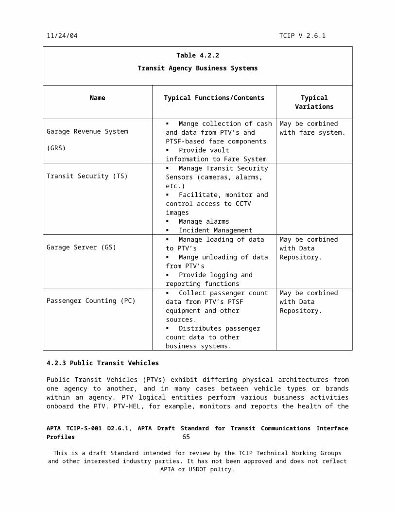
11/24/04 TCIP V 2.6.1
Scheduling(SCH)
Authorized TransitBusiness System
(Planning)
CAD/AVLSystem(CAD)
GIS
Transit Security(TS)
3*, C*
3**, C*
3**,
C**
2, B
Non TCIP Planning Products
Non TCIP Planning Inputs 2, B
1,4,A,DGM
L Maps G
ML
Map
s1,4,A
,D
Non TCIP Planning Products
Non TCIP Planning Inputs
Figure 5.2.4.1.ATCIP Dialogs and File Transfers Supporting Incident Planning Without Data Repository
Legend:
A - Infrastructure/Facility Information Subscribe Vehicle Inventory Subscribe Stoppoint List Subscribe Facilities Subscribe SheltersB - Subscribe Incident Report HistoryC - Schedules Subscribe Master Schedule Version Subscribe Route Schedule Subscribe Timepoints List Subscribe Pattern ListD - Geographical Information Subscribe Point Conversion Subscribe Route Geo Trace1- CptVehicleInventoryList CptStoppointList CptTransitFacilities CptShelterList2 - ImIncidentHistory3 - SchMasterScheduleVersion SchRouteSchedule SchTimepointList SchPatternList4 - SpPointConversion SpRouteGeoTrace*Normal, **Incident/Event Related
2, B
2, B
APTA TCIP-S-001 D2.6.1, APTA Draft Standard for Transit Communications Interface Profiles 67
This is a draft Standard intended for review by the TCIP Technical Working Groups and other interested industry parties. It has not been approved and does not reflect APTA or USDOT policy.
11/24/04 TCIP V 2.6.1
Scheduling(SCH)
Authorized TransitBusiness System
(Planning)
CAD/AVLSystem(CAD)
GIS
Transit Security(TS)
3*, C*
3**, C*
3**,
C**
2, B
2, B
Legend:
A - Infrastructure/Facility Information Subscribe Vehicle Inventory Subscribe Stoppoint List Subscribe Facilities Subscribe SheltersB - Subscribe Incident Report HistoryC - Schedules Subscribe Master Schedule Version Subscribe Route Schedule Subscribe Timepoints List Subscribe Pattern ListD - Geographical Information Subscribe Point Conversion Subscribe Route Geo Trace1- CptVehicleInventoryList CptStoppointList CptTransitFacilities CptShelterList2 - ImIncidentHistory3 - SchMasterScheduleVersion SchRouteSchedule SchTimepointList SchPatternList4 - SpPointConversion SpRouteGeoTrace*Normal, **Incident/Event Related
Figure 5.2.4.1.BTCIP Dialogs and File Transfers Supporting Incident Planning With Data Repository
Data Repository(DR)
GML Based Maps4, D
2, B
1,2,3*,4,A,B
,C*,D
2, B
1,2,3**,4,A,B,C**,D
Figures 5.2.4.1 A&B depict the TCIP information transfers associated with incident planning. The Data Repository or other agency data store may provide infrastructure, past incident, schedule, and/or geographical information to an Authorized Business System used by planners. Alternatively, this information may be retrieved
APTA TCIP-S-001 D2.6.1, APTA Draft Standard for Transit Communications Interface Profiles 68
This is a draft Standard intended for review by the TCIP Technical Working Groups and other interested industry parties. It has not been approved and does not reflect APTA or USDOT policy.

11/24/04 TCIP V 2.6.1
from other sources. The planners may modify schedules within the planning system(s), or alternative schedules may be developed using the Scheduling System. If events are planned for well in advance, then they can be associated with locally defined day-types. Since trips are associated in the schedule with day type(s) on which they are run, the designation of a day-type affect the trips scheduled for the day.
5.2.4.2 Security and Incident Management Preparation Stage
During the preparation stage the transit agency takes plans from the planning stage and implements actions to ensure the agency is ready to implement the plans. Activities in this stage include:
Training - employees on plans and procedures which may include classroom training, drills, etc. Construction – including facility and infrastructure upgrades, hardening, installation of cameras, sensors
and lighting, modification to PTVs etc. Stockpiling – Storing resources in locations where they will be needed in the event of an incident.
No TCIP information transfer requirements have been identified for the preparation stage of the Security and Incident Management Business Process.
5.2.4.3 Incident Detection, Classification, and Verification Stage
The prompt detection of incidents at the Transit Control Center is often one of the most critical factors in mounting an effective response. Detection occurs in a variety of ways including:
Voice notifications by telephone or radio from an agency employee, customer or other agency. News feeds to the control center Data notifications from a variety of sources and methods
o Incident Notifications from other agencies (transit, highway department, public safety, etc) governed by IEEE 1512
o Traveler Alarms from stations/Stoppoints (TCIP Report Traveler Alarm dialog) based on activation at a stoppoint by a traveler.
o Passenger Alarms onboard PTVs (TCIP Report Passenger Alarm dialog) based on an activation on the PTV by a passenger.
o Operator Alarms from onboard PTVs (TCIP Report Operator Alarm dialog) based on a noncovert alarm activation by the operator.
o Covert Alarms from onboard PTVs (TCIP Silent Alarm dialog) based on a covert alarm activation by the operator.
o Health Alarms from onboard PTVs (TCIP Subscribe PTV Health Alarms dialog)o Farebox Alarms from onboard PTVs (TCIP Subscribe Fare Collection Health dialog)o Farebox Alarms from station/stoppoint based fare collection equipment (TCIP Subscribe Fare
Collection Health dialog)o Incident Notifications from agency employees (TCIP Report Incident dialog).o A text or canned message from a PTV operator.o Observation of security cameras at a PTSF or on a PTV
Once the Control Center receives the notification, an incident report is created manually or automatically in the CAD/AVL System, Transit Security, Asset Management, and/or Operator Assignment System. Figure 5.2.4.3.A depicts some alternative the information flows for incident detection.
Each incident may be detected/reported by multiple sources and methods, and consequently different incidents may be opened in one or more business systems. Generally the agency will designate one business system to have the responsibility to assign incident identifiers and to combine duplicate incidents into a single incident to be managed. While different agencies may choose different business systems for this purpose, this section assumes the CAD/AVL system performs this function.
APTA TCIP-S-001 D2.6.1, APTA Draft Standard for Transit Communications Interface Profiles 69
This is a draft Standard intended for review by the TCIP Technical Working Groups and other interested industry parties. It has not been approved and does not reflect APTA or USDOT policy.

11/24/04 TCIP V 2.6.1
Depending on the reporting source/method and the nature of the incident, transit agency policy may require that the incident be verified. The purpose of verification is to ensure that the incident is real and that the initial report is substantially correct. Note that details in the initial report may be difficult to corroborate early in the incident. One of the most common verification mechanisms is to have a transit supervisor or manager go to the incident location to inspect and report on the situation. Notifications of the incident (see section 5.2.4.4) are generally held up or strictly limited while a required verification is underway.Classification of the incident also occurs in this stage. Classification may be performed by the reporter of the incident if the reporter is a trusted entity (e.g. supervisor), or classification may be performed in conjunction with verification of the incident if the source of the original report is suspect. During classification and verification, the geographical area affected may need to be determined (e.g. for a hazmat spill, public disturbance, major fire etc) and reported via an incident update. Similarly affected entities (agencies, responders, customers) may need to be identified. Figure 5.2.3.4.B illustrates alternative verification information flows.
APTA TCIP-S-001 D2.6.1, APTA Draft Standard for Transit Communications Interface Profiles 70
This is a draft Standard intended for review by the TCIP Technical Working Groups and other interested industry parties. It has not been approved and does not reflect APTA or USDOT policy.

11/24/04 TCIP V 2.6.1
CAD/AVL System
AssetManagement
(AM) PTV-FBX
PTSF-SEC
Figure 5.2.4.3. AIncident Detection Dialog Flows
PTV-OPR
PTV-SEC
PTV Operator
PTV Passenger
Traveler at Stoppoint/Station
PTSF-FBX
D
E
E
F,G
F,G,H
H
Legend:
A - Report IncidentB- Report Traveler AlarmC- Subscribe Fare Collection HealthD- Subscribe Fleet Health AlarmsE- Report Operator MessageF- Silent AlarmG- Report Operator AlarmH- Report Passenger AlarmI - Subscriber Video Feed
Dispatcher
TransitSupervisor
Traffic ManagementCenter Employee
Public SafetyEmployee
Other AgencyEmplolyee
EmergencyManagement
Public SafetyCAD
TrafficManagement
SPV
VerbalNotification
IEEE 1512IEEE 15
12
IEEE 1512
A
Fare System
C
TransitSecurity
(TS)
B, I
Transit SecurityCamera
Vendor Defined Camera System Interface
C
A
PTV SecurityCamera
I*
A,I
* Communications capacity may precludeusing this dialog enroute, or seriously diminish
frame rate or image quality
APTA TCIP-S-001 D2.6.1, APTA Draft Standard for Transit Communications Interface Profiles 71
This is a draft Standard intended for review by the TCIP Technical Working Groups and other interested industry parties. It has not been approved and does not reflect APTA or USDOT policy.

11/24/04 TCIP V 2.6.1
PTV Operator
PTV-COM
Dispatcher Transit Supervisor
Transit SecurityEmployee
CAD/AVLSystem SPV
TransitSecurity
PTSF-SEC
PTV-SEC
Verbal Verification
Verbal Verification
C
B
D
A
AA*
D
B
Legend:
A - Subscribe Video FeedB - Command Dispatch Incident ResponseC - Dispatch Initiated Voice Radio CallD - Report Incident Update * Communications capacity may precludeusing this dialog enroute, or seriouslydiminish frame rate or image quality
Figure 5.2.4.3.BIncident Verification Dialog Flows
A
APTA TCIP-S-001 D2.6.1, APTA Draft Standard for Transit Communications Interface Profiles 72
This is a draft Standard intended for review by the TCIP Technical Working Groups and other interested industry parties. It has not been approved and does not reflect APTA or USDOT policy.

11/24/04 TCIP V 2.6.1
5.2.4.4 Incident Notification
Once an incident is reported to the control center, and verified if necessary, the notification process begins. Various agencies use different approaches to the notification process, but for the purpose of discussion, we assume a verified incident is known to one of these 3 business systems:
CAD/AVL System Transit Security
Fare SystemPlanned incidents (e.g. major sporting, entertainment or political events) may be notified prior to the onset of the incident. In such cases the agency may begin ‘response’ type activities (e.g. pre-positioning PTVs, supervisors, etc.) prior to the incident affecting service.
As discussed in section 5.2.4.3, we assume, for illustrative purposes only, that in the example agency the CAD/AVL system is the central incident notification system. Accordingly incidents which are detected and verified in the Fare System or Transit Security are reported first to the CAD/AVL system and then reported on to additional business systems as appropriate. It is significant that some incidents within the agency are of no interest to other public agencies in the region (e.g. engine parameter fault on a PTV), while other incidents require wider notifications (e.g. PTV involved in a wreck). Similarly, some incidents may be reported to the public while others are not. In addition to the incident by incident decision to be made on whether to notify other agencies and the public, it is frequently necessary to filter or sanitize incident reports and updates that leave the agency’s control.
Agencies have a variety of different approaches to determining how widely incidents information will be disseminated. Some agencies have designated command center personnel who monitor activities and report appropriate information to Information Service Providers, media , and external agencies manually. Some agencies allow incident information to flow directly to public safety agencies filtered automatically by incident type.
Where incident detection, verification, notification and /or response activities rely heavily on business system to business system data communications, a keep-alive mechanism may be prudent so that the relevant business systems can continually verify that their counter part business system is ‘alive’. TCIP provides a dialog for this purpose “Subscribe Watchdog Timer”. This dialog is not shown in the information flow diagrams throughout this Concept of Operations, however agencies may elect to incorporate this dialog between business systems which need to be ‘alive’ at all times to respond to emergencies.
Figure 5.2.4.4 illustrates the use of TCIP and non TCIP information flows during the incident notification stage.
APTA TCIP-S-001 D2.6.1, APTA Draft Standard for Transit Communications Interface Profiles 73
This is a draft Standard intended for review by the TCIP Technical Working Groups and other interested industry parties. It has not been approved and does not reflect APTA or USDOT policy.

11/24/04 TCIP V 2.6.1
APTA TCIP-S-001 D2.6.1, APTA Draft Standard for Transit Communications Interface Profiles 74
This is a draft Standard intended for review by the TCIP Technical Working Groups and other interested industry parties. It has not been approved and does not reflect APTA or USDOT policy.
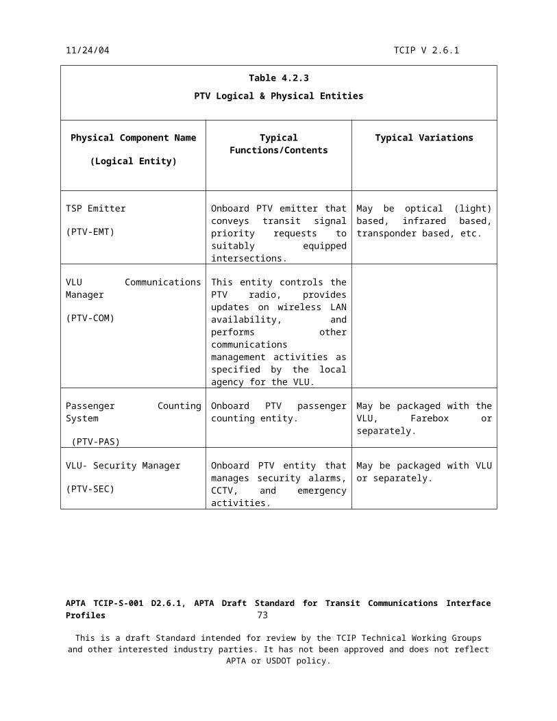
11/24/04 TCIP V 2.6.1
Traffic ManagementCenter Employee
CAD/AVLSystem
TrafficManagement
(TM)
SPV-OPR
PTV-OPR
TMV-OPR Fare System(FS)
TransitSecurity
(TS)
EmergencyManagement
Public SafetyCAD
CustomerService sytem
(CSS)
InformationServiceProvider
TravelerInformation
System(TRV)
Transit SecuritySupervisor
Dispatcher orDesignatedEmployee
Other AgencyEmployee
Public Safety Employee
IEEE 1512
IEEE 1512
IEEE 1512
IEEE 1512
A
A, C
A, C
A, B
A
A, B AA
A, B, C
Legend
A - Report IncidentB - Command Dispatch Incident ResponseC - Subscribe Incidents
Verbal Notification
Figure 5.2.4.4Incident Notification Information Flows
Notes: This diagram asumes that incident notification filtering isperformed by CAD/AVL. Agencies may designate other businesssystems to perform this function.
5.2.4.5 Security and Incident Response
Once the incident is reported to the Control Center, the response stage is executed. In this stage resources are mobilized to resolve, clear and close an incident. During this process, the Control Center may need to:
APTA TCIP-S-001 D2.6.1, APTA Draft Standard for Transit Communications Interface Profiles 75
This is a draft Standard intended for review by the TCIP Technical Working Groups and other interested industry parties. It has not been approved and does not reflect APTA or USDOT policy.

11/24/04 TCIP V 2.6.1
Request/Provide assistance to/from external agencies Request/Provide status to/from external agencies View video images of events at the incident location Receive and distribute incident updates from/to transit employees Implement and cancel detours Exchange text messages with PTV Operator(s), Transit Supervisors, or Transit Maintenance Vehicle
Operators Monitor covert audio from a stoppoint or PTV Clear/Cancel a silent alarm from a PTV Communicate by voice radio with PTV operators or other employees Change vehicle or operator assignments Dispatch agency responders to the incident (e.g. agency owned tow truck) Disable/Enable a PTV
The following subsections describe these processes.
5.2.4.5.1 External AgenciesInteractions with external agencies may be by voice (radio or telephone) or by data. Voice communications are based on local or regionally developed plans and procedures. Standardized interagency data exchanges to manage incidents are defined by IEEE 1512. Response stage information flows with external agencies are illustrated in figure 5.2.4.5.1.
APTA TCIP-S-001 D2.6.1, APTA Draft Standard for Transit Communications Interface Profiles 76
This is a draft Standard intended for review by the TCIP Technical Working Groups and other interested industry parties. It has not been approved and does not reflect APTA or USDOT policy.

11/24/04 TCIP V 2.6.1
APTA TCIP-S-001 D2.6.1, APTA Draft Standard for Transit Communications Interface Profiles 77
This is a draft Standard intended for review by the TCIP Technical Working Groups and other interested industry parties. It has not been approved and does not reflect APTA or USDOT policy.

11/24/04 TCIP V 2.6.1
CAD/AVLSystem
TrafficManagement
(TM)
TransitSecurity
(TS)
EmergencyManagement
Public SafetyCAD
IEEE 1512
IEEE 1512
IEEE 1512
A
A
Traffic ManagementCenter Employee
Transit SecuritySupervisor
Dispatcher orDesignatedEmployee
Other AgencyEmployee
Public Safety Employee
Legend
A - Report Incident UpdateVerbal Notification
Note: this diagram asumes that incident notification filtering isperformed by CAD/AVL. Agencies may designate other businesssystems to perform this function.
Figure 5.2.4.5.1Incident Response Stage Information Flows with External Agencies
5.2.4.5.2 View Video Images at the Incident Location
If the infrastructure (communications, bandwidth, and cameras) is in place, the authorized employees may be able to view near-real-time video imagery from the incident scene. It may be possible to present current images from a
APTA TCIP-S-001 D2.6.1, APTA Draft Standard for Transit Communications Interface Profiles 78
This is a draft Standard intended for review by the TCIP Technical Working Groups and other interested industry parties. It has not been approved and does not reflect APTA or USDOT policy.

11/24/04 TCIP V 2.6.1
selected camera or past images (e.g. back up to the incidents occurrence) from a PTV or PTSF. The Subscribe Video Feed dialog supports this capability, as illustrated in figure 5.2.4.5.2.
Agencies may elect to share incident video with external agencies. IEEE 1512 provides the ability to provide a URL to allow an authorized external agency to view agency video from an incident location. Transit Security may authorize such video sharing and may terminate the authorization at any time.
TransitSecurity
(TS)
PTSF-SEC
PTV-SEC
Camera System
Camera system
Legend
A - Subscribe Video FeedVendor Defined Camera System
InterfaceIntranet/Internet Streaming VideoFeed to Authorized Internal and
External Users
Figure 5.2.4.5.2Incident Video Image Distribution
A
A
5.2.4.5.3 Receiving and Distributing Incident Updates
As the incident progresses, verbal and/or data updates arrive at the control center. Agencies designate an appropriate business system to filter and distribute these updates. Here for discussion purposes, the CAD/AVL system is assumed. Updates are provided to the designated business system which then distributes them to authorized subscribers. Figure 5.2.4.5.3.A depicts the reporting of an incident update. Figure 5.2.4.5.3.B depicts the distribution of the update within the agency.
APTA TCIP-S-001 D2.6.1, APTA Draft Standard for Transit Communications Interface Profiles 79
This is a draft Standard intended for review by the TCIP Technical Working Groups and other interested industry parties. It has not been approved and does not reflect APTA or USDOT policy.

11/24/04 TCIP V 2.6.1
TMV Operator
Other Employee
Transit SecuritySupervisor
Transit Supervisor
PTV Operator
CAD/AVLSystem
TransitSecurity
(TS)
SPV-SEC
TMV-SEC
PTV-SEC
Dispatch
Legend
A - Report Incident Update
Verbal Report
A
A
A
A
Figure 5.2.4.5.3.AIncident Update Reporting Within the Transit Agency
APTA TCIP-S-001 D2.6.1, APTA Draft Standard for Transit Communications Interface Profiles 80
This is a draft Standard intended for review by the TCIP Technical Working Groups and other interested industry parties. It has not been approved and does not reflect APTA or USDOT policy.

11/24/04 TCIP V 2.6.1
TMV Operator
Other Employee
Transit SecuritySupervisor
Transit Supervisor
PTV Operator
CAD/AVLSystem
TransitSecurity
(TS)
SPV-SEC
TMV-SEC
PTV-SEC
Dispatch
Legend
A - Subscribe Incidents
Verbal Report
A
A
A
A
Figure 5.2.4.5.3.BIncident Update Distribution Within the Transit Agency
APTA TCIP-S-001 D2.6.1, APTA Draft Standard for Transit Communications Interface Profiles 81
This is a draft Standard intended for review by the TCIP Technical Working Groups and other interested industry parties. It has not been approved and does not reflect APTA or USDOT policy.

11/24/04 TCIP V 2.6.1
5.2.4.5.4 Implement and Cancel Detours
Depending upon the type and nature of the incident, it may be necessary to detour a PTV (or all PTVs on a route) from their normal path. After the dispatcher enters the appropriate information into the CAD/AVL System, the Report Detour dialog transfers the detour to the PTV. The Report Detour dialog provides the following features:
Ability to define way points along the detour Ability to add and delete timepoints and stoppoints to/from the trip Ability to change PTV’s scheduled timepoint arrival times beyond the detour Ability to change the PTV’s destination sign approaching and on the detour
When the detour is no longer required, the dispatcher enters the appropriate information into the CAD/AVL System and the Report Cancel Detour dialog conveys it to the impacted PTV(s).
The implementation and cancellation of detours is illustrated in Figure 5.2.4.5.4.
PTV Operator
CAD/AVLSystem
CustomerService System
(CSS)
Dispatcher
A
Legend
A - Report Detour Report Cancel Detour
Figure 5.2.4.5.4Implementing and Cancelling Detours
PTV-DAT
TravelerInformation
System(TRV)
A
A
5.2.4.5.5 Exchange Text Messages
TCIP provides the capability for PTV Operators, Supervisors, TMV Operators, and Dispatchers to exchange canned and/or freeform text messages. This ability allows a dispatcher to provide instructions on how to respond to the incident to operators, and for operators to provide incident status or other information to the dispatcher without tying up the voice radio. These capabilities are provided by the Report Dispatcher Message and Report Operator Message dialogs, as illustrated in Figure 5.2.4.5.5.
APTA TCIP-S-001 D2.6.1, APTA Draft Standard for Transit Communications Interface Profiles 82
This is a draft Standard intended for review by the TCIP Technical Working Groups and other interested industry parties. It has not been approved and does not reflect APTA or USDOT policy.

11/24/04 TCIP V 2.6.1
PTV Operator
CAD/AVLSystem
PTV-OPR
Dispatcher A
Legend
A - Report Operator MessageB -Report Dispatcher Message
Figure 5.2.4.5.5Text Message Exchanges Between Dispatchers, Supervisors, and Operators
TMV-OPR
SPV-OPR
A
A
B
B
B
TMV Operator
Supervisor
5.2.4.5.6 Monitor and Cancel Silent Alarms
On appropriately equipped PTVs, the PTV operator can actuate a covert (“silent”) alarm. This provides a notification to the dispatcher, and an acknowledgement back to the driver. In some agencies the acknowledgement is generated by the CAD/AVL System as soon as the alarm is received, on other agencies, the acknowledgement is withheld until the dispatcher indicates to the CAD/AVL System that he has seen the alarm. After the alarm is activated, the dispatcher maybe able to monitor events on the PTV using a covert microphone and an audio feed over the voice radio. At some point the operator indicates that the incident is over and cancels the alarm. The alarm remains active however, until the dispatcher confirms the incident closure.
5.2.4.5.7 Voice Communications between Dispatchers and PTV Operators
In the course of an incident it is frequently necessary for the dispatcher and PTV operator to converse on the voice radio. On many agencies a shared voice/data radio is used. Voice Communications can be initiated by either the Dispatcher or the PTV operator, and the PTV Operator may indicate that the need to communicate is urgent. In any case the Dispatcher (through the CAD/AVL System) has the ultimate control over which PTV operators are allowed to enter into voice conversations.
These capabilities are provided by the “Operator-Initiated Voice Radio Call” dialog and the “Dispatcher Initiated Voice Radio Call” dialog.
APTA TCIP-S-001 D2.6.1, APTA Draft Standard for Transit Communications Interface Profiles 83
This is a draft Standard intended for review by the TCIP Technical Working Groups and other interested industry parties. It has not been approved and does not reflect APTA or USDOT policy.

11/24/04 TCIP V 2.6.1
5.2.4.5.8 Change Vehicle or Operator Assignments
Incidents may force an agency to re-plan its operator and vehicle assignments or to change the trips assigned to a vehicle/operator pair. The changes may be entered by the maintenance or operations supervisors in the garage or the dispatcher may enter these changes into the CAD/AVL System. The “Command Load PTV Trips” dialog and/or the “Command Change Assignments” dialog transfer the new instructions to the PTV. Figure 5.2.4.5.8 depicts these interactions.
APTA TCIP-S-001 D2.6.1, APTA Draft Standard for Transit Communications Interface Profiles 84
This is a draft Standard intended for review by the TCIP Technical Working Groups and other interested industry parties. It has not been approved and does not reflect APTA or USDOT policy.

11/24/04 TCIP V 2.6.1
AssetManagement
(AM)
MaintenanceSupervisor
PTV-DAT(old PTV)
PTV-DAT(new PTV)
CAD/AVLSystem
A
A
A
Figure 5.2.4.5.8.AVehicle Assignment Change Initiated by Maintenance Supervisor
PTV-DAT(old PTV)
PTV-DAT(new PTV)
CAD/AVLSystem
A
A
Dispatcher
Figure 5.2.4.5.8.BVehicle Assignment Change Initiated by Dispatcher
OperatorAssignment
System(OAS)
Supervisor
PTV-DATCAD/AVLSystem
A
Figure 5.2.4.5.8.COperator Assignment Change Initiated by Garage Supervisor
PTV-DATCAD/AVLSystem
A
Dispatcher
Figure 5.2.4.5.8.DOperator Assignment Change Initiated by Dispatcher
Figure 5.2.4.5.8Incident Caused Operator and Vehicle Assignment Changes
LegendA - Command Change Assignments
A
APTA TCIP-S-001 D2.6.1, APTA Draft Standard for Transit Communications Interface Profiles 85
This is a draft Standard intended for review by the TCIP Technical Working Groups and other interested industry parties. It has not been approved and does not reflect APTA or USDOT policy.

11/24/04 TCIP V 2.6.1
5.2.4.5.9 Dispatch Agency Responders
The dispatcher, upon determining that agency responders are required at an incident location, requests or directs appropriate agency assets to the site. The “Command Dispatch Incident Response” dialog may be used to direct responders, or this may be done via voice communications, email, or using other agency-specified means. Figure 5.2.4.5.9 illustrates alternative scenarios for dispatching transit responders.
CAD/AVL
Dispatcher
SPV-OPRA
MaintenanceSupervisor
AssetManagement
(AM)
MaintenanceSupervisor
TMV-OPRA
TMV Operator
TransitSecurity
(TS)
Transit SecuritySupervisor
SPV-OPRA
Supervisor
Figure 5.2.4.5.9Example Alternative Agency Responder Dispatch Scenarios
LegendA - Command Dispatch Incident Response
Verbal Dispatch
5.2.4.5.10 Disable a PTV
In some severe circumstances (e.g. hijacking), a dispatcher may enter a command into the CAD/AVL System to disable an appropriately equipped PTV. The dialog “Command Remote PTV Disable” conveys the command to the PTV. Enable/Disable commands require a key code to be accepted by the PTV. Agencies may require that the dispatcher’s supervisor approve disabling a PTV due to numerous safety and liability issues involved. Figure 5.2.4.5.10 depicts this scenario.
APTA TCIP-S-001 D2.6.1, APTA Draft Standard for Transit Communications Interface Profiles 86
This is a draft Standard intended for review by the TCIP Technical Working Groups and other interested industry parties. It has not been approved and does not reflect APTA or USDOT policy.
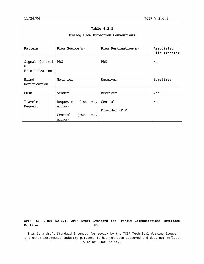
11/24/04 TCIP V 2.6.1
CAD/AVL
Dispatcher
PTV-SECA
Legend
A - Command Remote PTV DisableFigure 5.2.4.5.10
Remote Disable of PTVs
5.2.4.5.11 Cancel Trips
An agency may cancel scheduled trips in response to a planned or unplanned incident. Section 5.3.4.3.4 describes trip cancellation scenario.
5.2.4.6 Incident Recovery
In the incident recovery phase, the transit agency clears the incident and performs efforts necessary to return to normal service operations. These efforts can be negligible or extensive depending on the nature of the incident and its long term effects.
In the case of an incident involving a single PTV (e.g. breakdown, criminal act, accident) the agency may be able to dispatch another PTV and driver to resume the block/run beginning with the next scheduled trip for that PTV. The agency then determines what should be done about the passengers that were riding (or waiting for) the affected PTV. The agency may elect to do nothing and let the next following PTV on the same route pick up the extra passengers, or may dispatch a PTV to fill in the gap.
In the case of an incident resulting in the loss of access to a street, bridge out etc., the agency may be obliged to execute a detour in the short run. The agency may elect to republish the schedule if the outage is long term. Republishing the schedule could impact numerous business systems used for operations, customer service, traveler information etc. It could also cause the agency to republish timetables and other materials describing the affected route.
Figure 5.2.4.6 depicts the canceling of detours and re-enabling a PTV disabled during the incident response phase.
APTA TCIP-S-001 D2.6.1, APTA Draft Standard for Transit Communications Interface Profiles 87
This is a draft Standard intended for review by the TCIP Technical Working Groups and other interested industry parties. It has not been approved and does not reflect APTA or USDOT policy.

11/24/04 TCIP V 2.6.1
CAD/AVLSystem
Dispatcher
PTV-SEC
TravelerInformation
System(TRV)
CustomerServiceSystem(CSS)
PTV-DAT
Legend
A - Report Cancel DetourB - Command Remote PTV Enable
A
A
B
A
Figure 5.2.4.6Cancelling Detours and Re-enabling PTVs During Incident Recovery
5.2.4.7 Incident Follow Up
After an incident is cleared, additional follow-up efforts may be required. Depending upon the type of the incident it may be necessary to gather evidence for a criminal trial, and/or to recreate elements of the incident and the response to the incident as an input into future incident planning.
Video information is captured by cameras installed on PTVs and in PTSFs. This information is periodically unloaded to an archive or data store. During the follow up phase, these images may be retrieved for evaluation or use as evidence.
Business systems create log files of events as they transpire and these log files may provide useful information for recreating or evaluating incidents. Business system log files are not standardized by TCIP.
APTA TCIP-S-001 D2.6.1, APTA Draft Standard for Transit Communications Interface Profiles 88
This is a draft Standard intended for review by the TCIP Technical Working Groups and other interested industry parties. It has not been approved and does not reflect APTA or USDOT policy.
11/24/04 TCIP V 2.6.1
PTVs maintain logs of operating events while operating and this information is unloaded periodically to a data store or archive. During the follow up phase, these records may be retrieved for evaluation or used as evidence.
Closure of the incident occurs when all follow up actions are completed by all affected departments. Individual departments may send updates reflecting that the incident is closed from their point of view, however operations normally keeps the incident open until all affected departments indicate they are finished with their follow up actions.
Figures 5.2.4.7.A&B illustrate follow-up data collection scenarios with and without a data repository.
APTA TCIP-S-001 D2.6.1, APTA Draft Standard for Transit Communications Interface Profiles 89
This is a draft Standard intended for review by the TCIP Technical Working Groups and other interested industry parties. It has not been approved and does not reflect APTA or USDOT policy.

11/24/04 TCIP V 2.6.1
CAD/AVL
Analyst
PTV-SECPTSF-SEC
TransitSecurity
(TS)
AuthorizedBusinessSystem(ABS)
PTV-DAT
Figure 5.2.4.7.AIncident Data Collection During Follow Up Without Data Repository
A
C D
B B
Legend
A - Unload PTV Performance DataB - Unload Video ImagesC - Subscribe Daily Operating DataD - Subscribe Video Images
PTV-SEC
PTSF-SEC
AuthorizedBusinessSystem(ABS)
PTV-DAT
DataRepository
Analyst
Legend
A - Unload PTV Performance DataB - Unload Video ImagesC - Subscribe Daily Operating DataD - Subscribe Video Images
AB
B
C
Figure 5.2.4.7.BIncident Data Collection During Follow Up With Data Repository
TransitSecurity
D
APTA TCIP-S-001 D2.6.1, APTA Draft Standard for Transit Communications Interface Profiles 90
This is a draft Standard intended for review by the TCIP Technical Working Groups and other interested industry parties. It has not been approved and does not reflect APTA or USDOT policy.

11/24/04 TCIP V 2.6.1
5.3 PTV Operations
5.3.1 Purpose
The PTV Operations business process is the core of the transit business, and the most complex of the business processes defined in TCIP. This processes encompasses the actual preparation for service, operations in revenue, training, or ferry service, and the return to base for turnaround. The fundamental purpose of this business process is to transport transit customers.
5.3.2 Overview of PTV Operations
The major phases of this business process are: Preparation for Vehicle Operations Vehicle Operations Exceptions to Normal Operations Close-Out of Vehicle Operations
The Key organizational participants in this process are: Maintenance (Asset Management) who determine what vehicles are ready for service and control the
assignment of vehicles to blocks of work. Operating Supervisors – who ensure that the pull outs occur in a timely manner, that service is running
smoothly and procedures are followed, and who respond to various incidents and exception conditions. Dispatchers – who monitor service status and make adjustments based on events in real time throughout the
day.Challenges and constraints associated with this process include the perturbations introduced to smooth service delivery by traffic, incidents, late or sick operators, mechanical failures and other events. The dynamics of PTV movements especially on arterial streets can lead to “bus bunching” whereby PTVs operating on a route become unevenly spaced in time leading to poor service. This problem is most severe with bus service, but can occur with light and heavy rail service as well.
5.3.3 Primary Architecture Components
The key model architecture components related to PTV operations are:
PTV onboard entities – performs functions on PTVso PTV-ADH The logical entity on a public transit vehicle responsible for monitoring and
reporting schedule and route adherence.o PTV-ANN The logical entity on a public transit vehicle responsible for providing information
to passengers including announcements.o PTV-COM The logical entity on a public transit vehicle that manages the communications
links between the PTV and outside entities.o PTV-DAT The logical entity on a public transit vehicle responsible for data management
(within the Vehicle Logic Unit).o PTV-ECU The logical entity on a public transit vehicle associated with the engine control
unit.o PTV-EMT The logical entity on a public transit vehicle associated with the TSP Emitter.o PTV-HEL The logical entity on a public transit vehicle responsible for monitoring and
reporting on the health of the PTV and its onboard components.o PTV-LDS The logical entity on a public transit vehicle associated with the Location Data
Source.o PTV-LOC The logical entity on a public transit vehicle responsible for monitoring and
reporting the vehicle’s location.
APTA TCIP-S-001 D2.6.1, APTA Draft Standard for Transit Communications Interface Profiles 91
This is a draft Standard intended for review by the TCIP Technical Working Groups and other interested industry parties. It has not been approved and does not reflect APTA or USDOT policy.

11/24/04 TCIP V 2.6.1
o PTV-OPR The logical entity on a public transit vehicle associated with interactions with the vehicle operator.
o PTV-OTH Any agency-defined logical entity onboard a public transit vehicle. This entity’s functions are not defined by the Model Architecture.
o PTV-PAS A logical entity onboard a PTV responsible for monitoring and reporting passenger boarding/alighting.
o PTV-PRI A logical entity onboard a PTV responsible for managing transit signal priority functions, including the generation of priority requests.
o PTV-SEC A logical entity onboard a PTV responsible for managing security CAD/AVL – Manage PTVs in-service Asset Management (AM) – Get PTVs ready for service Operator Assignment System (OAS) – Ensure PTV share operators Garage Server (GS) – Load/unload PTV data files
5.3.4 Vehicle Operations Subprocesses
5.3.4.1 Preparation for Vehicle Operations
This section describes the process of getting a PTV prepared for operations. Although preparation for operation in revenue service is emphasized, most of this discussion is applicable to trips made for training, ferrying of PTVs, and maintenance as well.
5.3.4.1.1 Data Loading
The data loading process can occur at any time when the PTV is located within WLAN coverage or connected to a laptop to other loading device. Most commonly, loads occur when the vehicle returns after completion of a block of work and enters WLAN coverage, or upon power-up of the vehicle electronics. In either case the load pattern-based dialogs provide for the onboard logical entities to contact a designated fixed business system (usually the Garage Server [GS]) and determine if there are files to load. Figures 5.3.4.1.1.A, B&C depict this process.
These data loads include the following items (if required): Software (for any onboard components) Configuration Data (for any onboard components) Fare Data (to PTV-FBX) Schedule Data including trips, timepoints, stoppoints, link-maps, patterns Operator and Vehicle Assignments which may be for the whole fleet, a subset, or the single PTV being loaded Stop and Destination Annunciation Data (contains announcements, and destination sign contents for PTV-
ANN) Canned Message Texts to support efficient operator-dispatcher messaging Transit Signal Priority Business Rules (Not all PTVs are TSP-capable) Alarm Limits and other Parameters and Thresholds Background Map Images not all agencies use onboard map images, and map image scope may not cover all of
the PTV operating area.
The Garage Server (GS), Garage Revenue Server (GRS) or other business system designated by the agency, may or may not load the same files to all PTVs. The loads to the GS may specify that they are applicable to only certain PTVs or to certain PTV groups. PTV groups are defined and maintained by Asset Management (AM). The GS and GRS ensure that the correct version and updates are loaded to each PTV.
Although not shown in figure 5.4.4.1, other business systems may subscribe to fleet group definitions. Groups within the fleet may be defined based on the garage, vehicle type, brand/model of VLU, farebox, annunciator etc. Groups are not required to be mutually exclusive, thus an agency can define a group of PTVs with brand X
APTA TCIP-S-001 D2.6.1, APTA Draft Standard for Transit Communications Interface Profiles 92
This is a draft Standard intended for review by the TCIP Technical Working Groups and other interested industry parties. It has not been approved and does not reflect APTA or USDOT policy.

11/24/04 TCIP V 2.6.1
farebox, a group with brand Y farebox, a group with brand A VLU and a group with brand B VLU. A single vehicle might then belong (simultaneously) to groups A and X.
Some load dialogs permit a portions of a file to be updated without loading a new file version. Generally, these dialogs load files that contain a list of data frames (rows) that can be updated individually. The file load messages associated with row-updatable load files contain provisions to delete outdated rows, add new rows or replace existing rows. Row updating can significantly impact the time and communications capacity required to perform file loads to a PTV. Consult individual load dialog specifications in Annex D for information on which files are row-updatable.
The Garage Server (GS), and/or the Garage Revenue Server (GRS) may provide an alarm and or monitoring capability to allow the supervisor to ensure that PTVs that do not have the correct data loads are not allowed to pull out. Based on agency policies, PTVs may be allowed to pull out with outdated data loads, if the operators have been given special instructions or other agency specific procedures are followed.
The VLU may report an invalid schedule load (see section 5.5). The farebox may report an invalid fare set being loaded (see section 5.4). Agency procedures govern the handling of these situations.
Garage Server(GS)
AuthorizedBusinessSystem(ABS)
DataRepository
(DR)
AssetManagement
(AM)
Fare System(FS)
1,2 A,B
10, 11, J, K
1, 3, 4, 5, 6, 7, 9, 12,A,C,D,E, F,G,I, L
1, A
Figure 5.3.4.1.1.AGarage Server Data Loading Using a Data Repository
Legend
A - Load Component SoftwareB - Load Fare Collection DataC - Load ScheduleD - Load Destination and Stop AnnunciationsE - Load Canned Message TextF - Load TSP Business RulesG - Load PTV Alarm LimitsH - Load Operator AssignmentsI - Load Map ImageJ - Load Vehicle AssignmentsK - Subscribe Fleet Subset DefinitionsL - Load Day Types Subscribe Day Types
1 - CcOnboardSoftware CcOnboardConfigurationData2 - FcFareLoadData3 - SchRouteScheduleFile SchPatternFile SchTimepointsFile CptStoppointsFile4 - CcStopAndDestInfo5 - CcCannedMessageText6 - TspBusinessRules7 - CcPTVAlarmLimits8 - SchOperatorAssignmentFile9 - SpMapImageLoad10 - SchVehicleAssignmentFile11 - CptFleetSubsets12 - SchCalendarFile SchCalendar
OperatingAssignment
System(OAS)
8,H
GarageRevenue
Server (GRS)
APTA TCIP-S-001 D2.6.1, APTA Draft Standard for Transit Communications Interface Profiles 93
This is a draft Standard intended for review by the TCIP Technical Working Groups and other interested industry parties. It has not been approved and does not reflect APTA or USDOT policy.

11/24/04 TCIP V 2.6.1
Garage Server(GS)
CustomerService System
(CSS)
GIS
CAD/AVL
Fare System(FS)
OperatorAssignment
System(OA)
AuthorizedBusinessSystem(ABS)
AssetManagement
(AM)
8, H
1, 2, A, B
1, 5, 6, A,E,F
4, I
4, D
1, 7, 10, 11, A,G,J,K
1, A
Figure 5.3.4.1.1.BGarage Server Loading Without a Data Repository
Note: The identity of business systems providingdata loads will vary from agency to agency
Legend
A - Load Component Software Load Component Configuration DataB - Load Fare Collection DataC - Load ScheduleD - Load Destination and Stop AnnunciationsE - Load Canned Message TextF - Load TSP Business RulesG - Load PTV Alarm LimitsH - Load Operator AssignmentsI - Load Map ImageJ - Load Vehicle AssignmentsK - Subscribe Fleet Subset DefinitionsL - Load Day Types Subscribe Day Types
1 - CcOnboardSoftware CcOnboardConfigurationData2 - FcFareLoadData3 - SchRouteScheduleFile SchPatternFile SchTimepointsFile CptStoppointsFile4 - CcStopAndDestInfo5 - CcCannedMessageText6 - TspBusinessRules7 - CcPTVAlarmLimits8 - SchOperatorAssignmentFile9 - SpMapImageLoad10 - SchVehicleAssignmentFile11 - CptFleetSubsets12 - SchCalendarFile SchCalendar
SchedulingSystem(SCH)
3, 12, C, L
GarageRevenueServer(GRS)
APTA TCIP-S-001 D2.6.1, APTA Draft Standard for Transit Communications Interface Profiles 94
This is a draft Standard intended for review by the TCIP Technical Working Groups and other interested industry parties. It has not been approved and does not reflect APTA or USDOT policy.

11/24/04 TCIP V 2.6.1
PTV-ADH
PTV-FBX
PTV-OTH
PTV-DAT
PTV-SEC
Garage Server(GS)
PTV-PRI
PTV-OPR
PTV-HEL
PTV-LOC
PTV-ANN
PTV-COM
Legend:
A- Load Component Software Load Component Configuration DataB- Load Fare Collection DataC- Load ScheduleD- Load Destination and Stop AnnunciationsE- Load Canned Message TextF- Load TSP Business RulesG- Load PTV Alarm LimitsH- Load Operator AssignmentsI- Load Map ImageJ - Load Vehicle AssignmentsL - LoadDaytypes, or SubscribeDayTypesM** - Subscribe WLAN Status
Figure 5.3.4.1.1.CPTV Data Loading During the Preparation for Vehicle Operations Stage Using a Garage Server
A
A,F
A
A
A,E,I
MA,D
A,C,G
, H, J
, L
A
A
A
M
M
M
M
M
M
M
M
A,B
GarageRevenueServer(GRS)
*Any Logical entity on the PTV loaded with software and/or configuration data using these dialogs.**Any logical entity on the PTV may detect WLAN status using this flow
M
APTA TCIP-S-001 D2.6.1, APTA Draft Standard for Transit Communications Interface Profiles 95
This is a draft Standard intended for review by the TCIP Technical Working Groups and other interested industry parties. It has not been approved and does not reflect APTA or USDOT policy.

11/24/04 TCIP V 2.6.1
5.3.4.1.2 Vehicle Startup
The PTV Operator starts the vehicle electronics and the PTV’s engine. This triggers one or more instances of the Report Start Up Dialog. The PTV electronics run self diagnostics upon startup, which may include verification of the annunciator, engine/drivetrain status etc. The startup notification triggers the Asset Management System (AM) to initiate a Subscribe PTV Health Alarms dialog. This dialog causes the vehicle electronics to report the health status of the PTV and its onboard equipment. Figure 5.3.4.1.2 depicts this process.
AssetManagement
(AM)
PTV-HELA, B
Figure 5.3.4.1.2Vehicle Startup and Initial Health Reporting
Legend
A - Report Vehicle Start UpB - Subscribe PTV Health AlarmsC - Report Onbaord Component Health
Any OnboardComponent
C
5.3.4.1.3 Operator Sign-On and Inspection
Operators may sign on using a touch screen, key pad, magnetic card swipe, smart card, etc. In the case of a smart card other media, the operator may sign on using a reader connected to the farebox (PTV-FBX) (Figure 5.3.4.1.3.A) rather than the operator interface to the Vehicle Logic Unit (PTV-OPR) (Figure 5.3.4.1.3.B). In either case, the operator inspects the PTV to verify it is service ready. This inspection will include safety checks (e.g. tires, wipers, lights), and may include cycling the wheelchair lift/ramp or checking/exercising other agency designated subsystems or components. The inspection results are reported to the Asset Management system (AM).
Operator work assignments (runs) are made prior to the operator’s sign on to the PTV at the beginning of the shift. While the operator is already assigned to a run, the binding of the vehicle work block associated with that run to a specific PTV may or may not have occurred. In some agencies the vehicle bindings are performed in advance, and the operator has a specific assigned vehicle to use (Push Approach).
In other agencies the vehicle binding to a work block is deferred until the operator signs on to a PTV; causing the vehicle work block associated with the operator’s run to be bound to that vehicle (Pull Approach). In the pull approach the data load normally would contain bound operator assignments for a number of operators (e.g. the whole garage), and unbound vehicle assignments for a number of vehicles (e.g. vehicles assigned to the garage), and a bound vehicle assignment would be sent to the vehicle for that vehicle only-after the operator signed on. See Figure 5.3.4.1.3.C for an illustration of the pull approach.
Some agencies us a hybrid approach where the assignments are made in advance, but changed automatically if the operator signs on to a different PTV than expected. If the vehicle automated health checks (section 5.3.4.1.2) or the operator’s inspection determine that the vehicle is not service-ready, the vehicle assignment may be changed.
APTA TCIP-S-001 D2.6.1, APTA Draft Standard for Transit Communications Interface Profiles 96
This is a draft Standard intended for review by the TCIP Technical Working Groups and other interested industry parties. It has not been approved and does not reflect APTA or USDOT policy.

11/24/04 TCIP V 2.6.1
Figure 5.3.4.1.3.D depicts the change of PTVs in the hybrid approach. Figure 5.3.4.1.3.E depicts a change resulting from an inspection or health failure.
PTV-FBX
PTV-OPR
PTV Operator
AssetManagement
(AM)
Garage Server(GS)
Fare System(FS)
CAD/AVL
PTV-OTH
PTV-DAT
Farebox
Card Reader
A
AA
B,C
B
B, C
B,C
Figure 5.3.4.1.3.AOperator Sign-On Using Farebox Connected Card Reader
Legend
A - Subscribe Operator Sign-OnB - Report Operator Sign-OnC - Report Vehicle Inspection
PTV
APTA TCIP-S-001 D2.6.1, APTA Draft Standard for Transit Communications Interface Profiles 97
This is a draft Standard intended for review by the TCIP Technical Working Groups and other interested industry parties. It has not been approved and does not reflect APTA or USDOT policy.

11/24/04 TCIP V 2.6.1
PTV-OPR
PTV-FBX
PTV Operator
AssetManagement
(AM)
Garage Server(GS)
Fare System(FS)
CAD/AVL
PTV-OTH
PTV-DAT
A
AA
B,CB
B,C
B,C
Figure 5.3.4.1.3.BOperator Sign-On Using VLU Operator Interface
Legend
A - Subscribe Operator Sign-OnB - Report Operator Sign-OnC - Report Vehicle Inspection
PTV
APTA TCIP-S-001 D2.6.1, APTA Draft Standard for Transit Communications Interface Profiles 98
This is a draft Standard intended for review by the TCIP Technical Working Groups and other interested industry parties. It has not been approved and does not reflect APTA or USDOT policy.

11/24/04 TCIP V 2.6.1
PTV-OPR
PTV Operator
AssetManagement
(AM)
Garage Server(GS)
Fare System(FS)
CAD/AVL
PTV-DAT
PTV
A
B
A
B
A, B
B
Figure 5.3.4.1.3.C'Pull Approach' To Vehicle Assignment Binding
Legend
A - Report Operator Sign OnB - Push Vehicle Assignment (Bound)
APTA TCIP-S-001 D2.6.1, APTA Draft Standard for Transit Communications Interface Profiles 99
This is a draft Standard intended for review by the TCIP Technical Working Groups and other interested industry parties. It has not been approved and does not reflect APTA or USDOT policy.
11/24/04 TCIP V 2.6.1
PTV-OPR
PTV Operator
AssetManagement
(AM)
Garage Server(GS)
Fare System(FS)
CAD/AVL
PTV-DAT
PTV
A
B
A
B
A, B
B
Figure 5.3.4.1.3.DPTV Assignment Change Resulting from Unexpected Operator Sign-On in Hybrid Assignment Approach
Legend
A - Report Operator Sign OnB - Command Change Assignments
APTA TCIP-S-001 D2.6.1, APTA Draft Standard for Transit Communications Interface Profiles 100
This is a draft Standard intended for review by the TCIP Technical Working Groups and other interested industry parties. It has not been approved and does not reflect APTA or USDOT policy.

11/24/04 TCIP V 2.6.1
PTV-OPR
PTV Operator
Garage Server(GS)
AssetManagement
(AM)
Fare System(FS)
CAD/AVL
PTV-DAT
PTV
A
B
A
C
C
C
Figure 5.3.4.1.3.EVehicle Change Based on Health Alarm or Failed Inspection
Legend
A - Report Vehicle InspectionB - Subscribe PTV Health AlarmsC - Command Change AssignmentsD - Report Onboard Component Health
PTV
PTV-DAT
PTV-HEL
C
C
Note: Either A (manual Inspection) orB (automated alarm) can trigger AMto change the vehicle assignment.
Any OnboardComponent
D
5.3.4.1.4 Pull Out
The garage-based supervisor has responsibility for ensuring that the PTV Operator is fit for service (alert, sober, proper uniform, and other agency specified criteria). If the PTV operator is deemed not fit for service, this will normally result in an operator assignment change. If the PTV and the operator are ready for service, the supervisor allows the PTV to leave the garage at the time specified on a pull out list and reports the pull out (see Figures 5.3.4.1.4 A, B&C).
APTA TCIP-S-001 D2.6.1, APTA Draft Standard for Transit Communications Interface Profiles 101
This is a draft Standard intended for review by the TCIP Technical Working Groups and other interested industry parties. It has not been approved and does not reflect APTA or USDOT policy.

11/24/04 TCIP V 2.6.1
Supervisor
Garage Server(GS)
SPV-DAT
CAD/AVL
1, A
B
B
Legend
A - Subscribe Pull Out ListB - Report Pull Out1 - SchPullOutList
Figure 5.3.4.1.4.APTV Pull Out Reporting Using SPV
AssetManagement
(AM)
B
Supervisor
Garage Server(GS)
CAD/AVL
B
Legend
A - Subscribe Pull Out ListB - Report Pull Out1 - SchPullOutList
Figure 5.3.4.1.4.BPull Out Reporting Using the Garage Server
AssetManagement
(AM)
B
APTA TCIP-S-001 D2.6.1, APTA Draft Standard for Transit Communications Interface Profiles 102
This is a draft Standard intended for review by the TCIP Technical Working Groups and other interested industry parties. It has not been approved and does not reflect APTA or USDOT policy.

11/24/04 TCIP V 2.6.1
Garage Server(GS)
CAD/AVL
Legend
A - Subscribe Pull Out ListB - Report Pull Out1 - SchPullOutList
Figure 5.3.4.1.4.CAutomatic CAD/AVL Pull Out Reporting
AssetManagement
(AM)
1, A B
B
5.3.4.2 Normal PTV Operations
PTV operations differ significantly between transit agencies. This section describes these operations for a generic agency and illustrates TCIP interactions associated with those operations
5.3.4.2.1 PTV Movements
5.3.4.2.1.1 Deadhead to Initial Terminal
After the PTV leaves the garage, its first trip is usually from the garage to an initial stoppoint. This is reflected by a scheduled out-of-service trip containing two timepoints at the garage and at the first stoppoint. This trip is followed by a second in-service trip that starts with the initial stoppoint followed by a timepoint coincident with the initial stoppoint. The timepoint time associated with this timepoint reflects the scheduled departure time from the initial stoppoint. The PTV waits (usually with doors open) at the initial stoppoint until the scheduled departure time specified for the first timepoint.
5.3.4.2.1.2 In-Service Trips
Agencies may elect to include or omit stoppoint from the pattern segments that constitute the remainder of the revenue trip, however enroute timepoints are needed to establish schedule and route adherence.
If the trip contains a layover (PTV is scheduled to stop and wait for an interval at a stoppoint enroute), this is reflected by a coincident timepoint-stoppoint-timepoint sequence in the pattern for the trip. The timepoint time associated with the first timepoint reflects the scheduled arrival at the stoppoint, the timepoint time associated with the second timepoint indicates the scheduled departure from the layover stoppoint. This construct may be used to ensure PTVs remain at a stoppoint for a sufficient duration to allow transfers.
APTA TCIP-S-001 D2.6.1, APTA Draft Standard for Transit Communications Interface Profiles 103
This is a draft Standard intended for review by the TCIP Technical Working Groups and other interested industry parties. It has not been approved and does not reflect APTA or USDOT policy.

11/24/04 TCIP V 2.6.1
At the end of an in-service trip, the PTV may be scheduled for an out-of-service trip back to the garage, and out-of-service trip to a designated parking area (e.g. for an operator break), an out-of-service trip to another agency designated location, an out-of-service trip to the initial stoppoint for the next in-service trip, or may immediately be followed by another in-service trip.
5.3.4.2.1.3 Post In-Service Trips
Scheduled out-of-service trips following an in-service trip are similar to the out-of-service trip to the initial stoppoint. The trip contains a timepoint indicating the start location and time for the out-of-service trip. If the bus is to go to a location and park (e.g. for a break), the parking location is reflected by two sequential timepoints at the parking location. The timepoint times associated with the two timepoints at the parking location indicate the scheduled arrival and departure times at that location. A final timepoint in the out-of-service trip’s pattern indicates the endpoint for the out-of-service trip. If the out-of-service trip is back to the garage at the end of the PTV’s work block, it contains a timepoint for the location where the vehicle left service and a timepoint for the pull-in location. The timepoint times for these timepoints indicate the scheduled out-of-service and pull in times.
5.3.4.2.2 PTV Location Tracking
The current location of PTVs are of interest to a variety of transit entities including onboard entities, the CAD/AVL System, and other agency designated Authorized Business Systems (ABS).
The PTV’s raw location heading and speed is determined by the PTV-LDS entity (usually a GPS receiver). This entity reports raw location either directly to the Vehicle Logic Unit PTV-LOC entity, or over the Vehicle Area Network (VAN). If the PTV-LDS reports directly to the VLU, then PTV-LOC relays the information over the VAN to non-TCIP components.
PTV-LOC also obtains adherence information from PTV-ADH, schedule information from PTV-DAT, and provides location data to any other onboard subscriber entities via the “Subscribe Onboard Location” dialog. This dialog provides location updates: Initially on startup Periodically At the start and end of trips Upon arriving and departing stoppoints (if stoppoints are loaded to the PTV) At timepoints At event-locations specified in the pattern for the trip When the adherence status (schedule or route) changes
If PTV-LDS is connected to the VAN, it follows that any other VAN-connected onboard component can obtain location information directly from the VAN without using the “Subscribe Onboard Location” dialog. Such components will not , however, receive other information published using the “Subscribe Onboard Location” dialog such as adherence information.
PTV-LOC provides periodic location updates to CAD/AVL. This is accomplished using the “Subscribe PTV-AVL” dialog over a public or wideband wide area network. Location reporting to CAD/AVL may also be accomplished using the optional TCIP Polling Protocol (Annex H), or a proprietary vendor polling protocol. Other business systems that require near-real time PTV location information obtain this information from the CAD/AVL system using the “Subscribe Fleet Locations” dialog.
Figures 5.3.4.2.2 A&B illustrate the onboard distribution of PTV location. Figures 5.3.4.2.2 C&D illustrate the distribution of PTV location to fixed business systems.
APTA TCIP-S-001 D2.6.1, APTA Draft Standard for Transit Communications Interface Profiles 104
This is a draft Standard intended for review by the TCIP Technical Working Groups and other interested industry parties. It has not been approved and does not reflect APTA or USDOT policy.

11/24/04 TCIP V 2.6.1
PTV-FBX
PTV-OTH
PTV-OPRPTV-LOC
PTV-ANN
PTV-LDS
PTV-TSP
Legend:
A- Subscribe Onboard Location
A
VAN
Raw Location
Raw Location
A
A
A
A
Figure 5.3.4.2.2.AOnboard Distribution of PTV Location with PTV-LDS Directly Connected to VLU (PTV-LOC)
APTA TCIP-S-001 D2.6.1, APTA Draft Standard for Transit Communications Interface Profiles 105
This is a draft Standard intended for review by the TCIP Technical Working Groups and other interested industry parties. It has not been approved and does not reflect APTA or USDOT policy.

11/24/04 TCIP V 2.6.1
PTV-FBX
PTV-OTH
PTV-OPRPTV-LOC
PTV-ANN
PTV-LDS
PTV-TSP
Legend:
A- Subscribe Onboard LocationA
VAN
Raw LocationRaw Location
A
A
A
A
Figure 5.3.4.2.2.BOnboard Distribution of PTV Location with PTV-LDS Directly Connected to VAN
APTA TCIP-S-001 D2.6.1, APTA Draft Standard for Transit Communications Interface Profiles 106
This is a draft Standard intended for review by the TCIP Technical Working Groups and other interested industry parties. It has not been approved and does not reflect APTA or USDOT policy.

11/24/04 TCIP V 2.6.1
AuthorizedBusinessSystem(ABS)
PollingController
CAD/AVLSystem(CAD)
PTV-COM
Legend:
A-Notify PTV Polling ResultB- PollsC- Poll ResponsesD- Suscribe Fleet Location
Figure 5.3.4.2.2.C Distribution of PTV Location to Business Systems Using TCIP or Proprietary Polled Protocol.
BC
A
D
Note: Polling protocols used for transittypically provide 2 functions: The periodiclocation/status reporting to central, andtransport of general purpose messages.Polling is illustrated here because of itsrole in location distribution. Polling is notshown in other conops sections where itservers as a conduit for TCIP messages.
AuthorizedBusinessSystem(ABS)
CAD/AVLSystem(CAD)
PTV-LOC
Figure 5.3.4.2.2.DDistribution of PTV Location to Business Systems Using Public Wireless Networks.
Legend:
A- Subscribe PTV AVLB- Subscribe Fleet Locations A
B
APTA TCIP-S-001 D2.6.1, APTA Draft Standard for Transit Communications Interface Profiles 107
This is a draft Standard intended for review by the TCIP Technical Working Groups and other interested industry parties. It has not been approved and does not reflect APTA or USDOT policy.

11/24/04 TCIP V 2.6.1
5.3.4.2.3 PTV Operator Changes
From time to time agencies find it necessary to change PTV operators while the bus is enroute. These changes may be planned or unplanned. Planned (scheduled) changes may occur between trips or at a timepoint within a scheduled trip.
5.3.4.2.3.1 Scheduled Operator Changes
In the case of a scheduled operator change that occurs at the end of a trip, the vehicle assignment will contain a subsequent trip assigned to the PTV, but the operator assignment for the subsequent trip will have a different operator identifier.
If the scheduled operator change occurs mid-trip the pattern for the trip will include one or two timepoints at the operator change location. The old operator assignment will indicate that it ends at that timepoint identifier and the “new” operator assignment will indicate that it begins at that timepoint identifier. The timepoint identifier may be repeated with different timepoint times indicating that the vehicle is scheduled to arrive at the timepoint at the first timepoint time and depart at the other timepoint time. A single timepoint identifier indicates an ‘instantaneous’ operator charge that has no scheduled duration.
After arriving at the location where the operator change is scheduled, the “old” operator signs off and this is reported to the CAD/AVL System (and optionally to the dispatcher). Similarly the “new” operator signs on and this event is also reported to the CAD/AVL System, and optionally the dispatcher, as illustrated in Figure 5.3.4.2.3.1.
PTV-DAT PTV-OPR
CAD/AVL
Dispatcher
PTV Operator
Legend:
A- Subscribe Operator Sign OnB- Report Operator Sign Off Report Operator Sign-On
A
B
Figure 5.3.4.2.3.1Dialog Flows for Scheduled PTV Operator Change
GarageServer(GS)
FareSystem
(FS)
B
B
APTA TCIP-S-001 D2.6.1, APTA Draft Standard for Transit Communications Interface Profiles 108
This is a draft Standard intended for review by the TCIP Technical Working Groups and other interested industry parties. It has not been approved and does not reflect APTA or USDOT policy.

11/24/04 TCIP V 2.6.1
5.3.4.2.3.2 Unscheduled Operator Changes
If the operator change is unscheduled, the process of signing off and on is identical; however the notification to the PTV is different. In this case, PTV-DAT already has an operator assignment based on the earlier data load. This assignment is changed by the Supervisor in the Operator Assignment System (OAS) and communicated to the Garage Server (GS), Fare system (FS) PTV-DAT, and to the CAD/AVL System using the Command Change Assignments dialog.
The dialog flows for PTV operator changes are illustrated in Figure 5.3.4.2.3.2.
PTVDAT PTVOPR
CAD/AVLSystem(CAD)
Dispatcher
PTV Operator
Legend:
A-Subscribe Operator Sign OnB- Command Change AssignmentsC- Report Operator Sign Off Report Operator Sign-On
B
A
Figure 5.3.4.2.3.2Dialog Flows for Unscheduled PTV Operator Change
C
Supervisor
OperatorAssignment
System(OAS)
FareSystem
(FS)
GarageServer(GS)
B
B
B
B
5.3.4.2.4 Enroute Communications with Dispatcher
PTVs often operate for extended intervals without requiring any interaction with dispatchers beyond Automatic Vehicle Location monitoring as described in section 5.3.4.2.2. There are, however, occasions where communications by voice or data are required.
5.3.4.2.4.1 Voice Communications
The two major methods for dispatcher-operator voice communications are via radio or cell phone. PTV Operator Cell Phones are outside the scope of TCIP. Radio conversations may be initiated by the PTV operator or by the
APTA TCIP-S-001 D2.6.1, APTA Draft Standard for Transit Communications Interface Profiles 109
This is a draft Standard intended for review by the TCIP Technical Working Groups and other interested industry parties. It has not been approved and does not reflect APTA or USDOT policy.

11/24/04 TCIP V 2.6.1
Dispatcher. The dispatcher-initiated call can be to the operator or to the annunciator (PTV-ANN) to make a remote announcement.
Operator-initiated calls are shown on the CAD console, and normally must be accepted by the dispatcher prior to the call being set up. Some CAD consoles, however, support “unattended mode”. In this mode all operator-initiated calls are automatically accepted. These calls may be forwarded from the dispatch console to the dispatcher via a hand-held radio. In “unattended mode”, dispatchers cannot initiate a call back to vehicles. Some CAD consoles also support a fallback mode, wherein calls from PTVs are automatically accepted, and the dispatcher can communicate back to the PTVs on an all-call basis. CAD consoles may automatically revert to normal operations from unattended or fallback mode based on a configurable timer (e.g. 2 minutes).
Figures 5.3.4.2.4.1 A-C depicts the TCIP-supported voice call scenarios. Dialog flow lines follow the conventions defined in the model architecture, however supplemental dotted lines show additional message flows defined within the dialogs.
PTV Operator
PTV-COM PTV-OPR
CAD/AVL
Dispatcher
A*
AA
Voice
Legend
A - Operator Initiated Voice Radio Call* - Status Indication
Figure 5.3.4.2.4.1.AOperator-Initiated Voice Radio Call
APTA TCIP-S-001 D2.6.1, APTA Draft Standard for Transit Communications Interface Profiles 110
This is a draft Standard intended for review by the TCIP Technical Working Groups and other interested industry parties. It has not been approved and does not reflect APTA or USDOT policy.

11/24/04 TCIP V 2.6.1
PTV Operator
PTV-COM PTV-OPR
CAD/AVL
Dispatcher
A*
A
Voice
Legend
A - Operator Intiated Voice Radio Call* Status Indication
Figure 5.3.4.2.4.1.BDispatcher-Initiated Voice Radio Call to PTV Operator
APTA TCIP-S-001 D2.6.1, APTA Draft Standard for Transit Communications Interface Profiles 111
This is a draft Standard intended for review by the TCIP Technical Working Groups and other interested industry parties. It has not been approved and does not reflect APTA or USDOT policy.

11/24/04 TCIP V 2.6.1
APTA TCIP-S-001 D2.6.1, APTA Draft Standard for Transit Communications Interface Profiles 112
This is a draft Standard intended for review by the TCIP Technical Working Groups and other interested industry parties. It has not been approved and does not reflect APTA or USDOT policy.

11/24/04 TCIP V 2.6.1
PTV-ANN PTV-COM
CAD/AVL
Dispatcher
A*
AVoice Announcement
Legend
A - Operator Initiated Voice Radio Call* Status Indication
Figure 5.3.4.2.4.1.CDispatcher-Initiated Voice Announcement to PTV
5.3.4.2.4.2 Data Communications
Enroute data communications between the operator and dispatcher are possible in either direction. These communications can use prepackaged (canned) messages, which transmit message numbers in a fill in the blank format with blanks filled by entries from numbered lists, this mechanism provides a wireless network-efficient means of text exchange for conversations that are foreseeable. An example use of this capability would be to tell a driver to stop picking up passengers until a specified stoppoint is reached. This type of action might be taken in response to a bus bunching.
Freeform text communications between the driver and dispatcher are also supported by TCIP. These communications require the extra effort to type the message and are not as network-efficient as canned messages, but have the advantage of allowing completely ad-hoc messages to be exchanged.
Figure 5.3.4.2.4.2 A&B depicts dispatcher and operator initiated data messaging.
APTA TCIP-S-001 D2.6.1, APTA Draft Standard for Transit Communications Interface Profiles 113
This is a draft Standard intended for review by the TCIP Technical Working Groups and other interested industry parties. It has not been approved and does not reflect APTA or USDOT policy.

11/24/04 TCIP V 2.6.1
PTV-OPR
CAD/AVL
Dispatcher
PTV Operator
A
Legend
A - Report Dispatcher Message
Figure 5.3.4.2.4.2.ADispatcher to PTV Operator Freeform or Canned Message Delivery
APTA TCIP-S-001 D2.6.1, APTA Draft Standard for Transit Communications Interface Profiles 114
This is a draft Standard intended for review by the TCIP Technical Working Groups and other interested industry parties. It has not been approved and does not reflect APTA or USDOT policy.

11/24/04 TCIP V 2.6.1
PTV-OPR
CAD/AVL
Dispatcher
PTV Operator
A
Legend
A - Report Operator Message
Figure 5.3.4.2.4.2.BPTV Operator to Dispatcher Freeform or Canned Message Delivery
5.3.4.2.5 PTV Health and Parameter Monitoring
As the PTV progresses enroute, it is necessary to verify that the PTV and its onboard systems are operating normally. TCIP provides health alarm reporting dialogs for the PTV (as a whole) and for the farebox.
The default criteria for alarm generation (parameter ranges) are provided by the “Load PTV Alarm Limits” dialog executed during data loading (section 5.3.4.1.1). These limits can be overridden by parameter limit specifications in individual subscription requests for health alarms.
APTA TCIP-S-001 D2.6.1, APTA Draft Standard for Transit Communications Interface Profiles 115
This is a draft Standard intended for review by the TCIP Technical Working Groups and other interested industry parties. It has not been approved and does not reflect APTA or USDOT policy.

11/24/04 TCIP V 2.6.1
TCIP also provides a mechanism to subscribe to onboard parameters (e.g. water temperature, oil pressure) that are broadcast on the VAN. Normally there will be no active subscriptions to these parameters, however, a subscription can be initiated by a business system in response to an alarm.
Onboard components connected to the hub network report health using the “Report Onboard Component Health” dialog to PTV-HEL, PTV-HEL monitors the VAN and detects exceptions based on information broadcast on the VAN (e.g. oil pressure).
Alarm reporting from PTV-HEL can be either to the CAD/AVL or directly to Asset Management (AM). The optional TCIP Polling Protocol (Annex H) has health parameter/alarm reporting built into the polling process.
Figure 5.3.4.2.5.A depicts an enroute monitoring and reporting scenario without a reporting mechanism built into the wireless protocol. Figure 5.3.4.2.5.B depicts an enroute monitoring and reporting scenario using a polling protocol with health reporting built into poll responses.
VAN
PTV-HEL
CAD/AVLAuthorizedBusinessSystem(ABS)
Fare System(FS)
PTV-FBXPTV-OTH
AssetManagement
(AM)
A
A
B
C*
C*,D
EE
Legend
A - Report Onboard Component HealthB - Subscribe Fare Collection HealthC - Subscribe PTV ParametersD - Subscribe PTV Health AlarmsE - Subscribe Fleet Health Alarms* - CAD/AVL and AM may subscribe to different parameters and reporting rates
Figure 5.3.4.2.5.ADialog-Based Enroute PTV Health and Parameter Monitoring
SAE J1587
APTA TCIP-S-001 D2.6.1, APTA Draft Standard for Transit Communications Interface Profiles 116
This is a draft Standard intended for review by the TCIP Technical Working Groups and other interested industry parties. It has not been approved and does not reflect APTA or USDOT policy.

11/24/04 TCIP V 2.6.1
VAN
PTV-HEL
CAD/AVL
AuthorizedBusinessSystem(ABS)
Fare System(FS)
PTV-FBXPTV-OTH
AssetManagement
(AM)
A
A
B
C*
D
Legend
A - Report Onboard Component HealthB - Subscribe Fare Collection HealthC - Subscribe PTV ParametersD - Subscribe Fleet Health AlarmsE - PollF - Poll Result with Health Information* - CAD/AVL and AM may subscribe to different parameters and reporting rates
Figure 5.3.4.2.5.BPolling-Based Enroute PTV Health and Parameter Monitoring
PTV-COM
E
D
FC*
SAE J1587
PTV
5.3.4.2.6 Transit Signal Priority (TSP)
As the PTV operates on its trips it may encounter intersections that are equipped to provide priority treatment to PTVs (e.g. early green, extended green, phase rotation) to allow the PTV to operate more efficiently. Equipped intersections and agreeing on acceptable strategies for TSP requires extensive coordination between transit agencies, traffic management, and traffic engineering. Although a Priority Request Generator may request priority treatment; the traffic management system is not obliged to, and may not, grant it.
Commentary: The TCIP TSP business area draws heavily from dialogs, data and concepts defined in NTCIP 1211. This includes the Priority Request Generator (PRG). Priority Request Server (PRS), and all items defined in TCIP beginning with ‘SCP’. NTCIP 1211 requires that all communications to/from the PRS use SNMP. However, requests from the PRG need not necessarily be in SNMP format provided that a translator converts between SNMP and the alternative format – so that all communications to/from the PRS are SNMP formatted.
Priority Request Generators may consider any or all of the following in creating a priority request (based on data available to the PRG at the time the request is generated): Business Rules Schedule Adherence Status of PTV
APTA TCIP-S-001 D2.6.1, APTA Draft Standard for Transit Communications Interface Profiles 117
This is a draft Standard intended for review by the TCIP Technical Working Groups and other interested industry parties. It has not been approved and does not reflect APTA or USDOT policy.
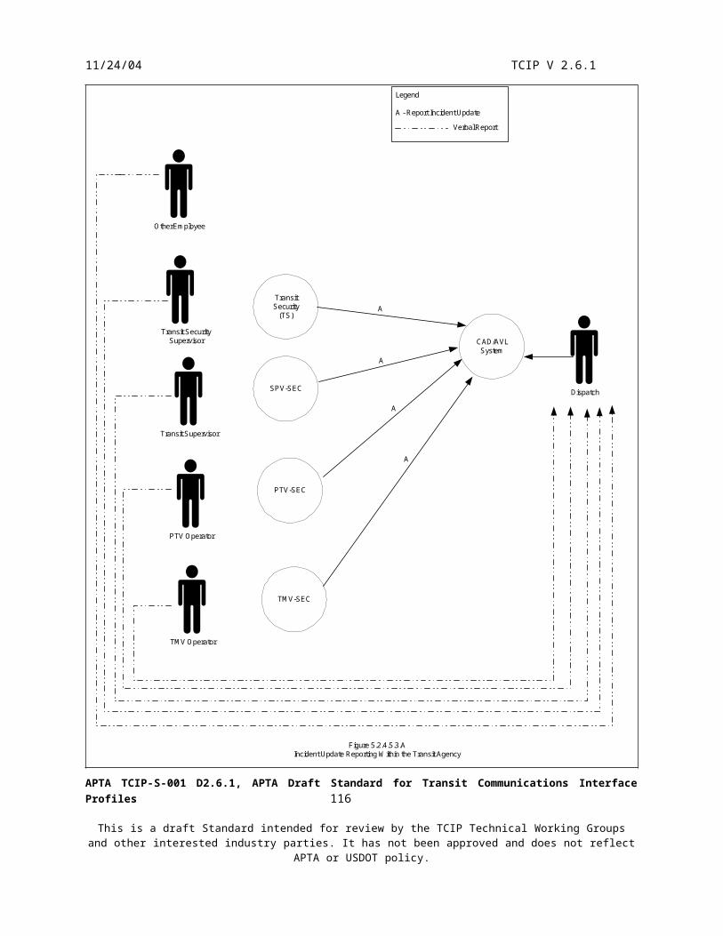
11/24/04 TCIP V 2.6.1
Time of Day Equipment Type at Intersection Passenger Loading on PTV Scheduled time for PTV’s current trip to arrive intersection (many agencies do not schedule to this level)
NTCIP 1211 defines four scenarios for TSP operation. In addition TCIP recognizes an emitter-based variation on Scenario #4, and an additional Scenario #5. These scenarios vary according to the physical location of the Priority Request Generator, and the path by which the priority request and its precursor information flows toward the Priority Request Server.
Figure 5.3.4.2.6 provides a conceptual overview of the entire TCIP process, independent of scenario numbers. Table 5.3.4.2.6 summarizes the various scenarios. Note that this figure includes the loading/unloading of information whereas the dialog flows later in this section only cover enroute operations. Loading dialog flows are included in section 5.3.4.1.1 and unloading dialog flows are included in section 5.3.4.4.3. Accordingly, the remainder of this section assumes that any required loading of information to the PTV was conducted during the preparation (pre-departure) stage.
TSP history data collections from both PRS and PRGs are required at the end of the operating day, or other locally specified interval. Section 5.3.4.4 discusses the closeout and collection of TSP and other operating data.
Note that network and server may cause priority requests to become “stale” before they can be processed. Implementing agencies should closely consider latency issues when implementing TSP.
Signal Priority Scenarios
Table 5.3.4.2.6
Scenario Figure Description
1
FleetManagement
Center
TrafficManagement
Center
Fleet Vehicle
PriorityRequest
GeneratorPriority
Request Server
Traffic SignalController
Coordinator
{PossiblyIntegrated
Signal Control PriorityScenario 1
The transit fleet vehicle carries a Priority Request Generator (PRG). Priority requests are sent through the transit fleet management center (control center) to the Traffic Management Center and onward to the Priority Request server in the field for processing. Response messages follow the reverse path. The onboard PRG is implemented by the TCIP logical entity PTV-PRI.
APTA TCIP-S-001 D2.6.1, APTA Draft Standard for Transit Communications Interface Profiles 118
This is a draft Standard intended for review by the TCIP Technical Working Groups and other interested industry parties. It has not been approved and does not reflect APTA or USDOT policy.

11/24/04 TCIP V 2.6.1
Signal Priority Scenarios
Table 5.3.4.2.6
Scenario Figure Description
2
FleetVehicle
TrafficManagement
Center
FleetManagement
Center
PriorityRequest
Generator
PriorityRequest Server
Traffic SignalController
Coordinator
{PossiblyIntegrated
Signal Control PriorityScenario 2
The Transit Fleet Management Center (control center) generates Priority requests which are sent through the Traffic Management Center to the Priority Request Server. Response messages follow the reverse path. The Transit Vehicle is not directly involved in the exchange.
3
FleetVehicle
TrafficManagement
Center
FleetManagement
CenterPriorityRequest
Generator
PriorityRequest Server
Traffic SignalController
Coordinator
{PossiblyIntegrated
Signal Control PriorityScenario 3
The Transit Fleet Management Center (control center) sends information about the transit fleet operations to the Traffic Management Center which generates priority requests to the Priority Request Server. Neither the transit vehicles nor the Transit control center are directly involved in the processing of priority requests or responses.
APTA TCIP-S-001 D2.6.1, APTA Draft Standard for Transit Communications Interface Profiles 119
This is a draft Standard intended for review by the TCIP Technical Working Groups and other interested industry parties. It has not been approved and does not reflect APTA or USDOT policy.

11/24/04 TCIP V 2.6.1
Signal Priority Scenarios
Table 5.3.4.2.6
Scenario Figure Description
4
FleetVehicle
TrafficManagement
Center
FleetManagement
Center
PriorityRequest
Generator
PriorityRequestServer
Traffic SignalController
Coordinator
{PossiblyIntegrated
Signal Control PriorityScenario 4-Message Based
The transit fleet vehicle carries a Priority Request Generator (PRG). Priority requests are sent directly to the Priority Request server in the field. Response messages follow the reverse path. Neither the transit control center, nor the Traffic Management Center is directly involved in the processing of priority requests or responses. This equates to NTCIP Scenario #4. The onboard PRG is implemented by the TCIP logical entity PTV-PRI.
4-Direct
FleetVehicle
TrafficManagement
Center
FleetManagement
Center
PriorityRequest
Generator
Reciever
Traffic SignalController
Coordinator
{PossiblyIntegrated
Signal Control PriorityScenario 4-Direct Link
Emitter
PriorityRequest Server
The transit fleet vehicle carries a Priority Request Generator (PRG). Priority Requests are initiated via a direct link from the vehicle to the intersection. Neither the Transit Control Center, nor the Traffic Management Center is directly involved in the processing of priority requests or responses. The onboard PRG is implemented by the TCIP logical entity PTV-PRI.
APTA TCIP-S-001 D2.6.1, APTA Draft Standard for Transit Communications Interface Profiles 120
This is a draft Standard intended for review by the TCIP Technical Working Groups and other interested industry parties. It has not been approved and does not reflect APTA or USDOT policy.

11/24/04 TCIP V 2.6.1
Signal Priority Scenarios
Table 5.3.4.2.6
Scenario Figure Description
5
FleetVehicle
TrafficManagement
Center
FleetManagement
Center
Priority RequestGenerator
Traffic SignalController
Coordinator
PossiblyIntegrated
Signal Control PriorityScenario 5
PriorityRequest Server
{{
The transit fleet vehicle conveys inputs to the request generation process to a roadside-based PRG. Neither the Transit Control Center nor the Traffic Management Center are directly involved in the processing of requests or responses.
APTA TCIP-S-001 D2.6.1, APTA Draft Standard for Transit Communications Interface Profiles 121
This is a draft Standard intended for review by the TCIP Technical Working Groups and other interested industry parties. It has not been approved and does not reflect APTA or USDOT policy.

11/24/04 TCIP V 2.6.1
Transit Management System* PTV**
PRS
Defined by NTICP 1211
Legend:TCIP XML or Narrowband MessageTCIP/NTCIP 1211 SNMP Message
* May be implemented by Data Repository and/or CAD/AVL. ** Contains multiple internal logical entities
SNMPTranslator
Analyze
Generate Requests
PTV Tracking
Data Storage
Business Rules
Subscribe PTV-AVL
Subscribe CC PRG Inputs
Load TSPBusiness Rules
Unload PRG Event
Subscribe PRS Event Log
Traffi cManagement
System
Alternative Implementation Approaches forTransferring:
Scp Priority RequestScp Priority UpdateScp Priority CancelScp Priority ClearScp Status ControlScp Status Buffer
TMS Defined Transfer Mechanism
Figure 5.3.4.2.6Scenario Independent Overview of Transit Signal Priority
PRG
APTA TCIP-S-001 D2.6.1, APTA Draft Standard for Transit Communications Interface Profiles 122
This is a draft Standard intended for review by the TCIP Technical Working Groups and other interested industry parties. It has not been approved and does not reflect APTA or USDOT policy.

11/24/04 TCIP V 2.6.1
5.3.4.2.6.1 Priority Request Scenario 1
The first priority request scenario is specified by NTCIP 1211 to include an onboard PTV Priority Request Generator (PRG). The request is generated onboard and transferred from the PTV to the CAD/AVL System, onward to the Traffic Management Center and then to the Priority Request Server.
In this scenario, PTV-PRI must have been loaded with the “Load TSP Business Rules” dialog. If PTV-PRI is in a component separate from the Vehicle Logic Unit (VLU), it receives real-time input from PTV-DAT via the Subscribe Onboard PRG Inputs dialog. Based on this dialog, or on information transferred within the VLU PTV-PRI detects the PTV’s approach to an intersection, selects a request strategy based on the business rules, and decides to send a signal priority request to the CAD/AVL System to be forwarded via the TMS to the PRS.
Implementation of this scenario requires close attention, by the transit agency as well as the traffic management agency, to ensure that cumulative network and server latencies do not excessively delay the priority request.
The communications from PTV-PRI may use TCIP narrowband or another agency-designated narrowband encoding, or XML to communicate the CAD/AVL System. The communications between the TMC and the CAD/AVL system must be SNMP as per NTCIP 1211. Figures 5.3.4.2.6.1.A, B & C depict these 3 sub scenarios within Scenario #1.
PTV-PRI
CAD/AVLSystem(CAD)
PRG
PTV-DAT
TrafficManagement
Center(TMC)
RDPRSLegend:
A- Subscribe Onboard PRG InputsB- Scp Priority Request Scenario 1*External to Transit
Figure 5.3.4.2.6.1.A Scp Scenario 1 Dialog Flows - All SNMP
Notes: 1. Assumes Load TSPBusiness Rules dialog previouslyexecuted 2. Dialog A is not requiredif PTV-DAT and PRV-PRI are bothlocated in VLU.
A
B (NTCIP 1211)
B* (NTCIP 1211)
B (NTCIP 1211)
APTA TCIP-S-001 D2.6.1, APTA Draft Standard for Transit Communications Interface Profiles 123
This is a draft Standard intended for review by the TCIP Technical Working Groups and other interested industry parties. It has not been approved and does not reflect APTA or USDOT policy.

11/24/04 TCIP V 2.6.1
PTV-PRI
CAD/AVLSystem
PRG
PTV-DAT
TrafficManagement
Center(TMC)
RDPRS
Legend:
A- Subscribe Onboard PRG InputsB- Scp Priority Request Scenario 1*External to Transit
Figure 5.3.4.2.6.1.B Scp Scenario 1 Dialog Flows - XML Within Transit
Notes: 1. Assumes Load TSPBusiness Rules dialog previouslyexecuted 2. Dialog A is not requiredif PTV-DAT and PRV-PRI are bothlocated in VLU.
A
B (TCIP-XML)
B (NTCIP 1211)
B* (NTCIP 1211)
APTA TCIP-S-001 D2.6.1, APTA Draft Standard for Transit Communications Interface Profiles 124
This is a draft Standard intended for review by the TCIP Technical Working Groups and other interested industry parties. It has not been approved and does not reflect APTA or USDOT policy.

11/24/04 TCIP V 2.6.1
PTV-PRI
CAD/AVLSystem
PRG
PTV-DAT
TrafficManagement
Center(TMC)
RDPRS
Legend:
A- Subscribe Onboard PRG InputsB- Scp Priority Request Scenario 1*External to Transit
Figure 5.3.4.2.6.1.C Scp Scenario 1 Dialog Flows - Narrowband Within Transit
Notes: 1. Assumes Load TSPBusiness Rules dialog previouslyexecuted 2. Dialog A is not requiredif PTV-DAT and PRV-PRI are bothlocated in VLU.
A
B (TCIP Narrowband or other narrowband encoding)
B (NTCIP 1211)
B* (NTCIP 1211)
5.3.4.2.6.2 Priority Request Scenario 2
This request scenario is specified by NTCIP 1211 to include the Priority Request Generator in the “Fleet Management Center”. This equates to the CAD/AVL System in the TCIP Model Architecture. The priority requests are sent to the Priority Request Server via the Traffic Management Center (TMC). The effect is that this scenario looks like scenario #1 to the TMC.
The CAD/AVL System determines the vehicle is approaching an intersection based on vehicle location determined as described in section 5.3.4.2.2. The CAD/AVL system has the business rules necessary to determine the appropriate priority request strategy and to forward that request to the TMC.
The “Scp Priority Request Scenario 2” dialog uses NTCIP 1211 SNMP-encoded messages. Figure 5.3.2.6.2 illustrates the dialog flows for scenario #2.
APTA TCIP-S-001 D2.6.1, APTA Draft Standard for Transit Communications Interface Profiles 125
This is a draft Standard intended for review by the TCIP Technical Working Groups and other interested industry parties. It has not been approved and does not reflect APTA or USDOT policy.

11/24/04 TCIP V 2.6.1
CAD/AVLSystem
TrafficManagement
Center(TMC)
RDPRS
Legend:
A- Scp Priority Request Scenario 2*External to Transit.
Figure 5.3.4.2.6.2Priority Request Scenario 2
PRG
A (NTCIP 1211)A* (NTCIP 1211)
5.3.2.6.3 Priority Request Scenario 3
This request scenario is specified by NTICP 1211 to include the Priority Request Generator in the Traffic Management Center. Information to support the creation of a priority request is sent to the TMC by the CAD/AVL System based on location reporting from the PTV. Note that the “Subscribe CC PRG Inputs” dialog does not use SNMP encoding. The TMC has business rules to determine the appropriate priority request strategy and to forward that request to the PRS. Figure 5.3.2.6.3 illustrates the dialog flows for scenario #3.
CAD/AVLSystem
TrafficManagementCenter (TMC)RDPRS
Legend:
A- Subscribe CC PRG InputsB- Priority Request*External to Transit.
Figure 5.3.4.2.6.3Priority Request Scenario 3
AB* (NTCIP 1211)
PRG
5.3.4.2.6.4 Priority Request Scenario 4
Scenario 4 is implemented with a PTV-based Priority Request Generator (PRG) that sends priority requests to the roadside Priority Request Server (PRS). PTV-PRI is loaded with business rules during the preparation for vehicle operations phase. These business rules allow the PRG within PTV-PRI to determine when to request priority. This scenario has two variations: an NTCIP 1211 message-based variation, and direct emitter variation common in many legacy implementations.
In the direct emitter variation the PRG within PTV-PRI requests signal priority by activating an emitter via the PTV’s VAN.
In the message-based variation, the PTG within PTV-PRI determines the appropriate priority request strategy to use and sends the priority request based on the business rules.
APTA TCIP-S-001 D2.6.1, APTA Draft Standard for Transit Communications Interface Profiles 126
This is a draft Standard intended for review by the TCIP Technical Working Groups and other interested industry parties. It has not been approved and does not reflect APTA or USDOT policy.

11/24/04 TCIP V 2.6.1
Figure 5.3.4.2.6.4 A & B illustrate the dialog flows for Priority Request Scenario 4.
PTV-EMT
PTV-PRI
RDPRS
RoadsidePriority
Receiver
PTV-DATPRG
Legend:
A- Subscribe Onboard PRG InputsB- Scp Priority Request Scenario 4-DirectC- Transmission to Wayside (Proprietary)D- Roadside Priority Request to Server (Proprietary)* Not required if PTV-PRI and PTV-DAT are both hostedin VLU
Figure 5.3.4.2.6.4.APriority Request Scenario 4 - Direct Emitter
A*(Hub)
B(VAN)
C
D
PTV-PRI
RDPRS
PTV-DATPRG
A*(Hub)
B (NTCIP 1211)
Legend
A - Subscribe Onboard PRG InputsB - Scp Priority Request Scenario 4 - Message Based* Not required if PTV-PRI and PTV-DAT are bothhosted in the VLU
Figure 5.3.4.2.6.4.BPriority Request Scenario 4 - Message Based
5.3.4.2.6.5 Priority Request Scenario 5
Scenario 5 was added to the NTCIP 1211 defined scenarios accommodate implementations where the PTV communicates directly to the roadside, but does not generate priority requests onboard. In this case, PTV-PRI sends priority request precursor information to a roadside-based PRG which generates a priority request to the
APTA TCIP-S-001 D2.6.1, APTA Draft Standard for Transit Communications Interface Profiles 127
This is a draft Standard intended for review by the TCIP Technical Working Groups and other interested industry parties. It has not been approved and does not reflect APTA or USDOT policy.

11/24/04 TCIP V 2.6.1
PRS. The roadside PRG contains necessary business rules to generate the request. Figure 5.3.4.2.6.5 illustrates the dialog flows for Scenario 5.
PTVTSP
RoadsidePRG
PTVDAT
RDPRS
Legend:
A - Suscribe Onboard PRG InputsB- Scp Priority Request Scenario 5C- Roadside Priority Request to Server(Proprietary)
Figure 5.3.4.2.6.5Priority Request Scenario 5
A
B
C
5.3.4.2.7 MDT Menu Sharing
As the PTV operates, onboard devices may need to interact with the PTV operator. These interactions may be simply to display a message to the operator and obtain an acknowledgement, or may require the operator to select a response from a list of alternatives (menu). There are two onboard mechanisms to accomplish this: via the VAN and via TCIP.
VAN-based menuing is defined by SAE J1587.
TCIP-based sharing is based on the Report Menu Selection dialog. Figure 5.3.4.2.7 illustrates the dialog flows for these interactions. TCIP includes a priority field in the menuing message to PTV-OPR to allow the order of menu presentation to the operator to be based on the urgency of the content.
APTA TCIP-S-001 D2.6.1, APTA Draft Standard for Transit Communications Interface Profiles 128
This is a draft Standard intended for review by the TCIP Technical Working Groups and other interested industry parties. It has not been approved and does not reflect APTA or USDOT policy.
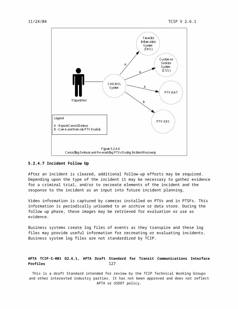
11/24/04 TCIP V 2.6.1
PTV-ADH PTV-FBXPTV-COM PTV-DAT PTV-SECPTV-PRIPTV-PASPTV-HEL PTV-LOCPTV-ANN
PTV-OPR
VAN
Legend:
A- Report Menu SelectionB- SAE J1587 Messaging
SAE J1587 - Appendix D Vehicle Control Head Keyboard Message Vehicle Control Head Display Message
Figure 5.3.4.2.7MDT Menu Sharing
A
B
AAAAAAAAA
PTVOperator
The potential operating scenarios in which the MDT Menu Sharing may be useful are far too numerous to enumerate, however a few examples are listed below:
PTV-HEL detects an alarm condition (e.g. high oil temperature) and displays an alarm to the operator with an ‘OK’ button for the operator to acknowledge seeing the alarm condition.
PTV-ANN provides a selection of operating modes and the operator selects an appropriate mode from the list.
Any device provides a list of configuration option alternatives, and the operator selects the appropriate setting. This might be available only in an administrator mode.
5.3.4.2.8 Passenger Counting
Some PTVs are equipped with automatic passenger counting equipment. Passenger counts are useful for reporting trips provided, for determining TSP strategies, and for validating fares collected. The logical entity in the TCIP model architecture associated with this function is PTV-PAS. This entity may be packaged in the VLU, farebox or other onboard component. PTV-PAS reports passenger counting results to the VAN (if connected) and to other TCIP entities via the hub network. Normally the report is triggered upon door closure and/or departure from each stoppoint. Figure 5.3.4.2.8 illustrates the onboard dialog flows for passenger counting.
Historical passenger count data is unloaded at the end of the day and provided to the Passenger Counting (PC) business system (see section 5.3.4.4).
The onboard passenger counting entity either subscribes to the onboard location reporting from PTV-LOC (see section 5.3.4.2.2) or if hosted in the VLU obtains location information within the VLU. This information allows the PTV-PAS entity to discern the beginning and end of trips, arrival and departure from stop points schedule adherence and other information. Depending on agency policy, PTV-PAS may automatically set the onboard passenger count value to zero at the end of each trip.
APTA TCIP-S-001 D2.6.1, APTA Draft Standard for Transit Communications Interface Profiles 129
This is a draft Standard intended for review by the TCIP Technical Working Groups and other interested industry parties. It has not been approved and does not reflect APTA or USDOT policy.

11/24/04 TCIP V 2.6.1
PTV-FBX
PTV-DAT
PTV-PRI
PTV-PAS
PTV-OTH
Legend:
A- Subscribe Onboard Passenger CountB - SAE J1587 Passenger Counter Patron Count
Figure 5.3.4.2.8Onboard Passenger Counting Dialog Flows
A
A
A
A
VAN
Door Status
PassengerCount Sensors
5.3.4.2.9 Traveler Request Inputs into PTV Operations
TCIP supports two mechanisms for travelers to interact in normal PTV Operations: Through On Demand Transfer Connection Protection Through On Demand Wheelchair Request
5.3.4.2.9.1 Transfer Connection Protection
Agencies may determine that certain scheduled transfers can be ‘protected’ either routinely or on demand. Routine transfer protections are appropriate where expected demand for a transfer is high (e.g. if a bus route stops at a subway station, and subway riders routinely transfer to the bus at that stop). Routine transfer protection can be built into the schedule as a note associated with the Route Schedule or Pattern, or can be provided as special instructions to the PTV Operator.
On Demand Transfer Connection is appropriate where expected demand for a transfer is intermittent and ridership is generally low. An example is late night runs where a missed connection might strand a rider for a prolonged period or overnight.
The Request Transfer Connection Protection dialog allows a traveler on a PTV, at a stoppoint, via the Customer Service or Traveler Information System (TRV) to request that a transfer connection be protected on their behalf. The request goes to the control center (CAD/AVL) where the bus to be held (“Waiter PTV”) is identified. The
APTA TCIP-S-001 D2.6.1, APTA Draft Standard for Transit Communications Interface Profiles 130
This is a draft Standard intended for review by the TCIP Technical Working Groups and other interested industry parties. It has not been approved and does not reflect APTA or USDOT policy.

11/24/04 TCIP V 2.6.1
control center may disapprove the request or forward it to the waiter PTV. Upon confirmation from the waiter PTV, the requester is notified of the approval. Upon a disapproval from the control center or a timeout on the confirmation from the waiter PTV a disapproval notice is sent to the requester. The wait instruction sent to the waiter PTV has an associated time limit, so that the waiter PTV is not stranded or excessively delayed by a no-show, or accessibly late requester.
Reasons the request might be disapproved include: Connection Protection System invalid request, and local agency defined denial criteria.
Figure 5.3.4.2.9.1 illustrates the on-demand transfer connection protection dialog flows.
RemoteTravelerSupport
(e.g. PDA)
Traveler
PTV Operator
Customer Service
Passenger
Passenger
Traveler
TravelerPTV-OPRCAD/AVL
PTV-FBX
PTV-OPR
CustomerServiceSystem(CSS)
PTSF-ANNKiosk
TravelerInformation
System(TRV)
Waiter PTV
A
A
A
VoiceA
A
A
A
A
Voice
Figure 5.3.4.2.9.1Transfer Connection Protection Request Flows
Legend
A - Request Transfer Connection Protection
APTA TCIP-S-001 D2.6.1, APTA Draft Standard for Transit Communications Interface Profiles 131
This is a draft Standard intended for review by the TCIP Technical Working Groups and other interested industry parties. It has not been approved and does not reflect APTA or USDOT policy.

11/24/04 TCIP V 2.6.1
5.3.4.2.9.2 On Demand Wheelchair Requests
Agencies may decide to provide a service where wheelchair travelers request ramp or lift service in advance at selected stoppoints. This request would allow the agency to ensure that a PTV with wheelchair access installed and operational is available to service the traveler.
The Request Wheelchair Pickup dialog allows a traveler on a PTV at a stoppoint, via the Customer Service System (CSS), or Traveler Information System (TRV) to request that wheelchair be provided and verified. The control center (usually CAD/AVL) can ensure that a selected PTV is able to service the request, and is notified of the need for a wheelchair pickup before sending an approval message to the requester. If the request cannot be honored for any reason the control center notifies the requester of the denial.
Figure 5.3.4.2.9.2 illustrates the on-demand wheelchair request dialog flows.
APTA TCIP-S-001 D2.6.1, APTA Draft Standard for Transit Communications Interface Profiles 132
This is a draft Standard intended for review by the TCIP Technical Working Groups and other interested industry parties. It has not been approved and does not reflect APTA or USDOT policy.

11/24/04 TCIP V 2.6.1
RemoteTravelerSupport
(e.g. PDA)
Traveler
PTV Operator
Customer Service
Passenger
Passenger
Traveler
TravelerPTV-OPRCAD/AVL
PTV-FBX
PTV-OPR
CustomerServiceSystem(CSS)
PTSF-ANNKiosk
TravelerInformation
System(TRV)
Waiter PTV
A
A
A
VoiceA
A
A
A
A
Voice
Figure 5.3.4.2.9.2wheelchair Pickup Request Flow
Legend
A - Request Wheelchair Pickup
5.3.4.2.10 PTV Annunciator
The PTV annunciator (PTV-ANN) obtains a data load as described in section 5.3.4.1.1. This data load specifies destination sign messages to be displayed along with the corresponding rules. It also specifies destination sign messages, passenger information sign messages and audio announcements to be displayed/played based on stoppoint arrivals and enroute events specified in the pattern for the trip.
The PTV annunciator obtains the current location and progress from PTV-LOC (either directly if hosted in the VLU, or via the “Subscribe Onboard Location” dialog if hosted in a separate component). This information includes start and end of trips, arrival and departure from stop points, and event notification. The PTV-ANN
APTA TCIP-S-001 D2.6.1, APTA Draft Standard for Transit Communications Interface Profiles 133
This is a draft Standard intended for review by the TCIP Technical Working Groups and other interested industry parties. It has not been approved and does not reflect APTA or USDOT policy.

11/24/04 TCIP V 2.6.1
logical entity uses current information to trigger the appropriate announcements and sign updates as the PTV proceeds enroute.
Figure 5.3.4.2.10 illustrates this process.
PTV-LOC PTV-ANN
Destination Signs
Passenger Information Sign
Audio Announcements
A
Legend
A - Subscribe Onboard LocationFigure 5.3.4.2.10Onboard Annunciator Operation
5.3.4.3 Exceptions to Normal Operations
Section 5.2 discusses incidents including dialog flows associated with incident reporting and management. That discussion includes detours and alarm management (silent, operator, and passenger) and is not replicated here. This section discusses schedule and route adherence exceptions, enroute trip changes, and trip cancellations.
5.3.4.3.1 Route Adherence
The route adherence function monitors and notifies the dispatcher whether a PTV is deviating from its assigned path for its current trip. Route adherence monitoring is performed onboard the PTV by the PTV-ADH entity, or centrally by the CAD/AVL System. The CAD/AVL System can perform this function by comparing vehicle location with the expected vehicle path based on the schedule for the assigned trip.
If the route adherence function is performed onboard, adherence information is provided to the CAD/AVL System either via (TCIP or proprietary) PTV poll responses and the “Notify Polling Result” dialog or the “Subscribe PTV Adherence” dialog. Default parameters associated with onboard adherence monitoring are provided to the PTV by the “Load PTV Alarm Limits” dialog during the preparation for vehicle operations phase (see section 5.3.4.1).
The frequency of off-route reporting using the “Subscribe PTV Adherence” dialog is defined by the “Load PTV Alarm Limits” dialog, however, the dispatcher can instruct the CAD/AVL System to send a revised query to PTV-ADH to adjust these parameters (off route distance, and reporting rate) or to cancel the adherence subscription. Note that canceling the adherence subscription impacts schedule adherence reporting as well as route adherence reporting. The dispatcher can effectively disable route adherence only by setting the minimum off route distance to a large value.
The frequency of off-route reporting using polling is governed by the poll cycle length on the radio channel. The dispatcher may, however, use the CAD/AVL System to put selected PTV(s) in a fast poll mode due to their off-route status. This is accomplished using the “Subscribe PTV-Polled Parameters” dialog.
APTA TCIP-S-001 D2.6.1, APTA Draft Standard for Transit Communications Interface Profiles 134
This is a draft Standard intended for review by the TCIP Technical Working Groups and other interested industry parties. It has not been approved and does not reflect APTA or USDOT policy.

11/24/04 TCIP V 2.6.1
The parameters provided in the “Load PTV Alarm Limits” dialog provide ability to specify criteria under which a vehicle is determined to recover from off-route status. These include: transiting a specified number of timepoints or stoppoints along the original route, or returning to within a specified distance of the original route.
Figures 5.3.4.3.1 A-D illustrate route adherence dialog flows in each scenario.
PollingController
CAD/AVL
PTV-ADH
CAD/AVL
PollingController
CAD/AVL
PTV-LOC
CAD/AVL
Figure 5.3.4.3.1.ACAD/AVL Based Route Adherence Monitoring with Polling
Note: Dialog A provides vehiclelocation which is used by CAD/AVLto infer adherence. Dialog B sets thepolling rate (fast or normal).
LegendA - Notify PTV Polling ResultB - Subscribe PTV-Polled Parameters
A B A
LegendA - Subscribe PTV-AVL
Note: Dialog A provides vehiclelocation which is used by CAD/AVL to infer adherence.
Figure 5.3.4.3.1.BCAD/AVL Based Route Adherence Monitoring- No Polling
A B
LegendA - Notify PTV Polling ResultB - Subscribe PTV-Polled Parameters
Note: Dialog A provides vehicle-calculated adherence status to CAD/AVL. Dialog B sets polling rate (fastor normal)
Figure 5.3.4.3.1.CPTV-Based Route Adherence Monitoring with Polling
A
LegendA - Subscribe PTV Adherence
Note: Dialog A providesvehicle-calculated adherencestatus to CAD/AVL.
Figure 5.3.4.3.1.DPTV-Based Route Adherence Monitoring- No Polling
5.3.4.3.2 Schedule Adherence
The schedule adherence function monitors and notifies the dispatcher whether a PTV is maintaining its assigned schedule for a current trip. Usually schedule adherence is measured by comparing actual and scheduled times at timepoints included in the trip pattern. Schedule adherence monitoring may be performed onboard the PTV by the PTV-ADH entity, or centrally by the CAD/AVL System. The CAD/AVL System can perform this function by
APTA TCIP-S-001 D2.6.1, APTA Draft Standard for Transit Communications Interface Profiles 135
This is a draft Standard intended for review by the TCIP Technical Working Groups and other interested industry parties. It has not been approved and does not reflect APTA or USDOT policy.

11/24/04 TCIP V 2.6.1
comparing vehicle location send times (obtained from the “Notify Polling Result” dialog or the “Subscribe PTV AVL” dialog), with the scheduled timepoints for the assigned trip.
If the schedule adherence function is performed onboard, adherence information is provided to the CAD/AVL System either via PTV poll responses and the “Notify Polling Result” dialog or the “Subscribe PTV Adherence” dialog. Default parameters associated with onboard adherence monitoring are provided to the PTV by the “Load PTV Alarm Limits” dialog during the preparation for in-service operations phase.
The schedule adherence criteria using the Subscribe PTV Adherence dialog is defined by the “Load PTV Alarm Limits” dialog, however, the dispatcher can instruct the CAD/AVL System to send a revised query to PTV-ADH to adjust these parameters, (off schedule early late tolerance) or to cancel the adherence subscription. Note that canceling the subscriptions impacts route adherence reporting as well as schedule adherence reporting. The dispatcher can effectively disable schedule adherence by setting the off schedule tolerance to large values.
The location reporting frequency using polling is governed by the poll cycle length on the radio channel. The dispatcher may, however, use the CAD/AVL System to put selected PTV(s) in a fast poll mode due to their off-route status. This is accomplished using the “Subscribe PTV-Polled Parameters” dialog.
Figure 5.3.3.2 A-D illustrate schedule adherence dialog flows.
APTA TCIP-S-001 D2.6.1, APTA Draft Standard for Transit Communications Interface Profiles 136
This is a draft Standard intended for review by the TCIP Technical Working Groups and other interested industry parties. It has not been approved and does not reflect APTA or USDOT policy.
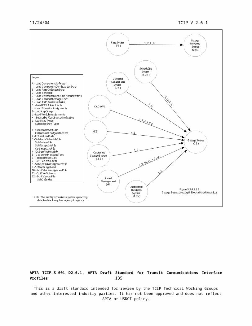
11/24/04 TCIP V 2.6.1
PollingController
CAD/AVL
PTV-ADH
CAD/AVL
PollingController
CAD/AVL
PTV-LOC
CAD/AVL
Figure 5.3.4.3.2.ACAD/AVL Based Schedule Adherence Monitoring with Polling
Note: Dialog A provides vehiclelocation which is used by CAD/AVLto infer adherence. Dialog B sets thepolling rate (fast or normal).
LegendA - Notify PTV Polling ResultB - Subscribe PTV-Polled Parameters
A B A
LegendA - Subscribe PTV-AVL
Note: Dialog A provides vehiclelocation which is used by CAD/AVL to infer adherence.
Figure 5.3.4.3.2.BCAD/AVL Based Schedule Adherence Monitoring- No Polling
A B
LegendA - Notify PTV Polling ResultB - Subscribe PTV-Polled Parameters
Note: Dialog A provides vehicle-calculated adherence status to CAD/AVL. Dialog B sets polling rate (fastor normal)
Figure 5.3.4.3.2.COnboard Based Schedule Adherence Monitoring with Polling
A
LegendA - Subscribe PTV Adherence
Note: Dialog A providesvehicle-calculated adherencestatus to CAD/AVL.
Figure 5.3.4.3.2.DCAD/AVL Based Schedule Adherence Monitoring- No Polling
5.3.4.3.3 Enroute Trip Changes
Occasionally it becomes necessary to change plans for a PTV after it has departed the garage. Section 5.2.4.5.4 describes the ability for the dispatcher to implement a detour. In some cases it is not appropriate to use a detour, and instead it is necessary to change a PTV’s assignment to another scheduled trip or to a newly created trip or set of trips.
If the new trip(s) have already been defined to PTV-DAT using the “Load Schedule” dialog in the preparation for vehicle operations phase, the dispatcher can simply reassign the PTV from one trip to another. The “Command Change Assignments” dialog accomplishes this function. Agency-specific policies and procedures govern the process for moving between assigned trips including discharging passengers, going out-of-service, moving to the appropriate location to begin the newly assigned trip, etc. Normally, this will include a voice conversation between the dispatcher and the PTV operator.
APTA TCIP-S-001 D2.6.1, APTA Draft Standard for Transit Communications Interface Profiles 137
This is a draft Standard intended for review by the TCIP Technical Working Groups and other interested industry parties. It has not been approved and does not reflect APTA or USDOT policy.

11/24/04 TCIP V 2.6.1
If the new trip has not already been defined to PTV-DAT, then it is necessary to define the trip along with the reassignment. This is accomplished using the “Command Load PTV Trips” dialog. Agencies must use caution in implementing this dialog, as the message to the PTV converting the new trip(s) host the potential to be large and impact the radio link performance, or cause the message to be rejected by the TCIP Polling Controller.
Figures 5.3.4.3.3 A-B illustrate the dialog flows for enroute trip changes.
PTV-DAT
CAD/AVLSystem(CAD)
PTV-OPRPTV-COM
PTV Operator
Dispatcher
Legend:
A- Dispatcher Initiated Voice Radio CallB- Command Change Assignments
Figure 5.3.4.3.3 AEnroute Trip Change - New Trip Previously Loaded
ABVoic
e
A
PTV-DAT
CAD/AVLSystem(CAD)
PTV-OPRPTV-COM
PTV Operator
Dispatcher
Legend:
A- Dispatcher Initiated Voice Radio CallB- Command Change PTV Trips
Figure 5.3.4.3.3 BEnroute Trip Change - New Trip Not Previously Loaded
ABVoic
e
A
APTA TCIP-S-001 D2.6.1, APTA Draft Standard for Transit Communications Interface Profiles 138
This is a draft Standard intended for review by the TCIP Technical Working Groups and other interested industry parties. It has not been approved and does not reflect APTA or USDOT policy.

11/24/04 TCIP V 2.6.1
5.3.4.3.4 Canceling Scheduled Trips
From time to time it becomes necessary to cancel scheduled trips for operational reasons due to unplanned schedule changes, etc. TCIP provides two mechanisms to accomplish this action:
Schedule Updates – If the cancellation is known far enough in advance, row updates can be performed on the schedule to add, modify, or delete trips from the schedule. This occurs via the schedule distribution process discussed in section 5.5, and the loading processes (to PTVs) discussed in section 5.3.4.1.1.
Cancellations Without Schedule Updates – If the cancellation is not known in advance, or the agency does not want to wait to perform a schedule update, the cancellations may be performed using the “Notify Trip Cancellations” dialog.
The “Notify Trip Cancellations” dialog allows the control center to specify that groups of trips will be cancelled for: The current day A list of specified days A list of specified day-types
Figure 5.3.4.3.4 illustrates the use of the “Notify Trip Cancellations” dialog.
CAD/AVLSystem
Dispatcher
GarageServer(GS)
DataRepository
(DR)
TravelerInformation
System(TRV)
CustomerServiceSystem(CSS)
PTV-DAT
Legend
A - Notify Trip Cancellations1 - CcCancelTrips
Figure 5.3.4.3.4Cancellation of Trips Without a Schedule Update
A
1, A
1, A
1, A
1, A
APTA TCIP-S-001 D2.6.1, APTA Draft Standard for Transit Communications Interface Profiles 139
This is a draft Standard intended for review by the TCIP Technical Working Groups and other interested industry parties. It has not been approved and does not reflect APTA or USDOT policy.

11/24/04 TCIP V 2.6.1
5.3.4.3.5 Reporting Service Events
A PTV operator may encounter a variety of events while providing service, such as noticing damage or graffiti at stoppoints, gang activity, sick passengers, etc.
Figure 5.3.4.3.5 depicts the reporting of these types of events, with a data repository.
PTV-OPR
DataRepository
(DR)
CAD/AVLSystemPTV-DAT
DispatcherPTV Operator
A A
B
Legend
A - Report Service EventB - Unload PTV Performance Data
Figure 5.3.4.3.5Reporting and Logging Service Events
5.3.4.4 Close Out of Normal Operations
After completing service the PTV normally returns to the bus garage. A variety of post service activities may take place including:
Recording the pull-in to the garage Removing cash and tokens from the farebox Unloading data from the PTV Logoff and shutdown
In addition to the individual PTV closeout operations, there is a closeout with the Traffic Management Center, and another closeout with PTSF entities. These closeouts may occur on a daily or other periodic basis specified by local policies.
5.3.4.4.1 Recording the Pull-In
The PTV’s final trip of the day will normally be an out-of-service trip containing a final timepoint at the garage. The scheduled timepoint time for this final timepoint and the scheduled pull-in time will correspond.
The garage-supervisor may obtain a list of scheduled pull-ins from the Garage Server (GS), using a Supervisor Portable or vehicle (SPV). The supervisor will report the pull in, along with the actual pull-in time. Pull-In times may be significant to an agency due to overtime liability, labor agreements, etc.
Other Pull in scenarios include housing the supervisor report directly to the Garage Server (GS), or having pull-ins detected automatically by the CAD/AVL System.
Figure 5.3.4.4.1 A-C illustrate the Pull in reporting process.
APTA TCIP-S-001 D2.6.1, APTA Draft Standard for Transit Communications Interface Profiles 140
This is a draft Standard intended for review by the TCIP Technical Working Groups and other interested industry parties. It has not been approved and does not reflect APTA or USDOT policy.

11/24/04 TCIP V 2.6.1
GarageServer(GS)
SPV-DAT
Supervisor
Fare System(FS)
AssetManagement
(AM)
CAD/AVL
B
B
B
1, A B
Figure 5.3.4.4.1.ARecording the Pull In to the Garage Using an SPV
Legend
A - Subscribe Pull In ListB - Report Pull In1 - SchPullInList
GarageServer(GS)
Supervisor
Fare System(FS)
AssetManagement
(AM)
CAD/AVL
B
B
B
Figure 5.3.4.4.1..BRecording the Pull In to the Garage Using the Garage Server
Legend
A - Subscribe Pull In ListB - Report Pull In1 - SchPullInList
APTA TCIP-S-001 D2.6.1, APTA Draft Standard for Transit Communications Interface Profiles 141
This is a draft Standard intended for review by the TCIP Technical Working Groups and other interested industry parties. It has not been approved and does not reflect APTA or USDOT policy.
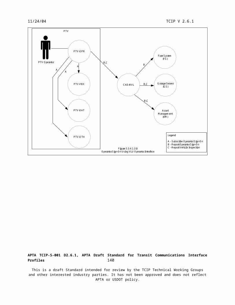
11/24/04 TCIP V 2.6.1
GarageServer(GS)
Fare System(FS)
AssetManagement
(AM)
CAD/AVL
B
B
B
Figure 5.3.4.4.1..CAutomatic CAD/AVL-Based Pull In Reporting
Legend
A - Subscribe Pull In ListB - Report Pull In1 - SchPullInList
5.3.4.4.2 Removing Cash and Tokens
The cashbox and tokens may be removed at the garage, or the bus may go to a separate location to have the cashbox removed. Cashboxes may be removed nightly, or allowed to remain on the PTV for a period of days depending on local agency policies. When the cashbox is removed by an authorized employee, the event and the cashbox contents are reported by the PTV to the Garage Revenue System (GRS) and the Fare System (see Figure 5.3.4.4.2). Additional information about fare reporting is described in section 5.4.
GarageRevenueSystem(GRS)
FareSystem
PTV-FBX A, B 1, A, B
Figure 5.3.4.4.2Reporting the Cashbox Removal and Unloading Fare Data
Legend
A - Unload Fare Collection DataB - Report Cashbox Event1 - FcUnloadData
5.3.4.4.3 Unloading Data from the PTV
The logical entities onboard the PTV collect and log data throughout the work assignments. When the PTV returns to wireless LAN coverage, this information needs to be removed (unloaded) from the PTV to a longer term data store. Local agency architectures may define variations on the business systems shown as data stores in this section.
Data to be unloaded includes: Fare Collection Data
APTA TCIP-S-001 D2.6.1, APTA Draft Standard for Transit Communications Interface Profiles 142
This is a draft Standard intended for review by the TCIP Technical Working Groups and other interested industry parties. It has not been approved and does not reflect APTA or USDOT policy.

11/24/04 TCIP V 2.6.1
PTV Performance Data which includes vehicle time/motion information as well as vehicle health and alarm information
Transit Signal Priority Data (PRG Event Log) Video Images captured onboard the PTV
Passenger count data is included in the PTV Performance data unload. This information is required by the Passenger Counting (PC) business system. The Garage Server (GS) extracts this information and provides it to the Passenger Counting business system. The Passenger Counting (PC) business system provides passenger count information to other authorized business systems that require it. (e.g. planning, GIS).
Similarly vehicle health/mechanical data is included in the PTV Performance Data unload to the Garage Server (GS). The Garage Server extracts this information and provides it to the Asset Management System (AM).
Figures 5.3.4.4.3 A&B illustrate the unloading of data from the PTV with and without a Data Repository.
PTV-FBX
PTV-DAT
GarageServer
GarageRevenueServer(GRS)
Fare System(FS)
DataRepository
(DR)
PassengerCounting
(PC)
AssetManagement
(AM)
TransitSecurity
(TS)
PTV-SEC
A
B, C
D
5, F*
4, E*
2, 3,
B, C
1, A
Figure 5.3.4.4.3.AUnloading Data from the PTV With a Data Repository
Legend
A - Unload Fare Collection DataB - Unload PTV Performance DataC - Unload PRG Event LogD - Unload Video ImagesE - Subscribe Fleet Passenger DataF - Subscribe Fleet Mechanical DataG - Subscribe Traveler Request Log
1 - FcUnloadData2 - CcPTVPerformanceData3 - TspEventLogUnload4 - CcFleetPassengerData5 - CcFleetMechanicalData6 - CcTravelerRequestLog* - Data extracted from vehicleperformance data by Garage Server
CustomerServiceSystem(CSS)6, G
APTA TCIP-S-001 D2.6.1, APTA Draft Standard for Transit Communications Interface Profiles 143
This is a draft Standard intended for review by the TCIP Technical Working Groups and other interested industry parties. It has not been approved and does not reflect APTA or USDOT policy.

11/24/04 TCIP V 2.6.1
PTV-FBX
PTV-DAT
GarageServer
GarageRevenueServer(GRS)
Fare System(FS)
CAD/AVLSystem
PassengerCounting
(PC)
AssetManagement
(AM)
TransitSecurity
(TS)
PTV-SEC
A
B, C
D
5*, F*
4*, E*
2, 3,
B, C
1, A
Figure 5.3.4.4.3.BUnloading Data from the PTV Without Data Repository
Legend
A - Unload Fare Collection DataB - Unload PTV Performance DataC - Unload PRG Event LogD - Unload Video ImagesE - Subscribe Fleet Passenger DataF - Subscribe Fleet Mechanical DataG - Subscribe Traveler Request Log
1 - FcUnloadData2 - CcPTVPerformanceData3 - TspEventLogUnload4 - CcFleetPassengerData5 - CcFleetMechanicalData6 - CcTravelerRequestLog* - Data extracted from vehicleperformance data by Garage Server
CustomerServiceSystem(CSS)6*, G*
5.3.4.4.4 Logoff and Shutdown
The final events of a work day from a PTV perspective, are the sign off by the PTV Operator and possibly a PTV Shutdown. Note that some agencies do not shutdown PTVs after a work block-especially in colder climates. Also, many implementations do not shutdown the computers onboard a PTV promptly when the engine is shut off. This may allow data unloads to complete prior to computers shutting down and effectively disabling the various PTV logical entities. The operator may also report vehicle defects at the end of the day. This is accomplished using the same dialog used for the pre-trip inspection (Report Vehicle Inspection). Figure 5.3.4.4.4 illustrates these activities.
APTA TCIP-S-001 D2.6.1, APTA Draft Standard for Transit Communications Interface Profiles 144
This is a draft Standard intended for review by the TCIP Technical Working Groups and other interested industry parties. It has not been approved and does not reflect APTA or USDOT policy.

11/24/04 TCIP V 2.6.1
PTV-OPR
PTV Operator
GarageServer(GS)
PTV-OTH
PTV-FBX
OperatorAssignment
System(OAS)
CAD/AVL
FareSystem
(FS)
PTV-HEL
AssetManagement
(AM)
A,C
D
D
B
A
B,C
A
A
Figure 5.3.4.4.4Operator Logoff and Vehicle Shutdown Reporting
Legend
A - Report Operator Sign OffB - Report Vehicle Shut DownC - Report Vehicle InspectionD - Subscribe Operator Sign On
5.3.4.4.5 Non PTV Closeouts
In addition to the data obtained from the PTV at the end of the day, other operating data is obtained from fixed entities as well.
The periodic closeout with the traffic management area obtains TSP history data from TMC and field based PRG(s) and/or PRS(s). This provides a basis for evaluating the effectiveness of the TSP System(s) installed.
The periodic closeout with the stoppoint of station entities includes cashbox event reporting, fare collection data unloading and video image recovery from PTSF-FBX and PTSF-SEC.
The periodic closeout of traveler requests (for connection protection and/or wheelchair pickups) involves data pushed from CAD/AVL and TRV to the CSS.
Figure 5.3.4.4.5 illustrates these processes.
APTA TCIP-S-001 D2.6.1, APTA Draft Standard for Transit Communications Interface Profiles 145
This is a draft Standard intended for review by the TCIP Technical Working Groups and other interested industry parties. It has not been approved and does not reflect APTA or USDOT policy.

11/24/04 TCIP V 2.6.1
RoadsidePriority
RequestServer
Fare System(FS)
TransitSecurity
(TS)
DataRepository
(DR)
PTSF-FBX
PTSF-SEC
CAD/AVL
TrafficManagement
Center(TMC)
1, A
2, B
2, B
4, E
3, C, D
PRG
Figure 5.3.4.4.5Closeout of Non-PTV Entities
Legend
A - Subscribe PRS Event LogB - Unload PRG Event LogC - Report Cashbox EventD- Unload Fare Collection DataE - Unload Video ImagesF - Push Traveler Request Log
1 - ScpEventLog2 - TspEventLogUnload3 - FcUnloadData4 - CcUnloadImages5 - CcTravelerRequestLogPush
TravelerInformation
System(TRV)
CustomerServiceSystem(CSS)
5, F
5, F
APTA TCIP-S-001 D2.6.1, APTA Draft Standard for Transit Communications Interface Profiles 146
This is a draft Standard intended for review by the TCIP Technical Working Groups and other interested industry parties. It has not been approved and does not reflect APTA or USDOT policy.

11/24/04 TCIP V 2.6.1
5.4 Fare Collection and Revenue Management
5.4.1 Purpose of Fare Collection and Revenue Management
The fare collection and revenue management process deals with all aspects of a transit agency’s fare policies and operations. These include determining fares, collecting fares, handling exception conditions, managing media and cash, and dealing with security and accounting reconciliation issues.
Fare policies are locally determined based on a complex process involving local and regional political considerations, agency revenue needs and sources, ridership forecasts and other factors. Since fare policies are highly agency dependent, TCIP provides some basic capabilities which may be tailored to individual agency needs.
The transit industry is currently developing a Universal Transit Farecard Standard (UTFS), sometimes called a smartcard. Many aspects of the Revenue Management and Fare Collection business process will fall under the UTFS standardization umbrella including back office communications with financial institutions, farecard content, validation security requirements, and reader/writer requirements.
5.4.2 Overview of Fare Collection and Revenue Management
The fare collection and revenue management process consists of 8 major sub processes:
Fare Policy Fare Media Sales/Vending Revenue/Media Collection Revenue Reconciliation Banking Security System Maintenance System Configuration
TCIP does not define:
Regional clearinghouse functions Regional integration of backend fare and financial systems Interfaces to banks Interfaces to merchants (e.g. commercial fare media vendors) Fare media
o Content o Form factoro Communications/reader protocol
Encryption schemes
TCIP does define:
A mechanism to transfer (“load”) software and/or manufacturer-defined configuration data to fareboxes and other fare equipment.
A mechanism to load fare policies, fare zones, etc to fareboxes fare vending equipment. A mechanism to remotely disable/enable fareboxes or fare equipment. A mechanism to report cash box and vaulting events and contents.
APTA TCIP-S-001 D2.6.1, APTA Draft Standard for Transit Communications Interface Profiles 147
This is a draft Standard intended for review by the TCIP Technical Working Groups and other interested industry parties. It has not been approved and does not reflect APTA or USDOT policy.

11/24/04 TCIP V 2.6.1
A mechanism to report the log of farebox or fare equipment events. A mechanism to report farebox and fare equipment health alarms and/or security alarms. A mechanism to report the fare(s) associated with a planned itinerary.
These mechanisms are intended to support a wide array of agency fare policies and procedures, but may need to be extended to support some locally defined requirements.
Some key challenges and constraints associated with fare collection and revenue management include:
Fare Policy Complexity – Fare policy is driven by a wide variety of local business and political concerns. This results in widely divergent fare policies from one agency to another. Some agencies define very large numbers (>1000) different fare variations within a single agency.
Agency Differences – Agencies adopt significantly different approaches to fare policy including but not limited to paying by ride by distance, by zone, by customer class, etc. Some agencies use cash only, but increasingly agencies are adopting a variety of different fare media.
Regional Policy Coordination – Agencies benefit (through increased ridership) by making it convenient for customers to transfer between transit systems, and modes within a regional area. This results in a need for regional coordination of fare policies and procedures. This is especially true when agencies implement smart card technologies and allow the card to be used on an interagency basis.
Security/Theft/Fraud – Agencies experience ongoing attempts by customers, employees and others to improperly extract cash, monetary transfers, and free service from the agency through a wide variety of techniques including burglary, embezzlement, robbery, fraud and forgery. Agencies must diligently and continuously implement and execute security processes and procedures to counter these threats.
Small Market – The marketplace for transit fare equipment is small compared to the market for other manufactured devices. This problem is exacerbated by different fare policies which result in equipment designs which are not universally applicable across the transit industry. This fragments an already small market. The small market limits commercial investment in research and development of fare equipment for transit, and drives up costs.
Culture – Partially due to the very real need for security, and partially due to human nature, fare and revenue organizations in transit agencies and the vendors for those agencies tend to be very reluctant to provide open interfaces to fare/revenue systems and equipment. This drives the industry towards stovepipe solutions, inhibits data sharing, and adds complexity to operations (e.g. multiple PTV operator logons).
Communications Security – There is a need to ensure that communications conveying revenue-critical information are adequately protected. This may require some communications to be encrypted, authenticated, or otherwise protected and/or authenticated.
Future issues to be addressed in the fare collection and revenue management area include:
Integration Across Modes – Increasingly agencies require the ability to ‘seamlessly’ transfer among transit modes. This presents particular challenges when fare procedures differ by mode. For example subway systems generally collect fares in stations and control access using turnstiles or fare gates, whereas bus systems often collect fares at boarding. BRT systems may collect fares at the station and issue a ticket as proof of payment. Paratransit customers may pay on boarding or be billed separately from the trip (e.g. monthly credit card billing).
Non Transit Cards – The use of non-transit fare media is popular with transit riders, but presents challenges for transit agencies. These cards include commercial credit cards (American Express®, Discover®, Visa®, Mastercard®, etc.), and corresponding band-branded smart cards issued by the banking industry. Additionally government agencies are issuing a variety of magnetic and smartcards which can be used as identification, or as a transit fare
APTA TCIP-S-001 D2.6.1, APTA Draft Standard for Transit Communications Interface Profiles 148
This is a draft Standard intended for review by the TCIP Technical Working Groups and other interested industry parties. It has not been approved and does not reflect APTA or USDOT policy.

11/24/04 TCIP V 2.6.1
media. Non transit cards may require separate fare reconciliation mechanisms, as well as different procedures for loading cards and for obtaining reimbursement for transit services provided. Issuers of these cards may charge a fee deducted from the fare reimbursement for the use of these cards.
Parking Garage Management – Agencies often provide park and ride services where commuters drive from their home to a commuter facility, park their cars in a parking lot or garage and then board a transit vehicle. The parking facilities may be operated by the transit agency, a private contractor (concessions), or by a completely distinct private company. Commuters would prefer to use the same media to pay for fares and parking.
ITS Initiatives – The Intelligent Transportation Systems initiatives continue to evolve over time. The Integrated Transportation Corridor Initiative and the Mobility Services for all Americans Initiative may impact fare collection and revenue management approaches in the future.
CEN Fare Management System Architecture (FMSA). The European Committee for Standardization (CEN) has developed a standard on architectures for fare management systems. Since fare system vendors may sell equipment both in the US and Europe, this standard may impact US fare systems in the future.
APTA Universal Transit Farecard Standard (UTFS) – APTA is developing a standard for fare media and for a variety or related fare/revenue processing activities. This standard will impact the development of smart card and magnetic card systems in the US. UTFS is expected to handle the bulk of the requirements for fare media standardization (particularly card and content specifications), and as a result TCIP does not provide requirements in these areas. UTFS is also working on a set of fare/revenue security guidelines for transit.
5.4.3 Primary Architectural Components
The Key components of the Model Architecture involved in the Fare Collection and Revenue Management business process are:
Fare System – This is the agency business system that manages fare policies, fare reconciliation, interfaces to the regional clearinghouse, banks, etc.
Garage Revenue Server – This business system provides the link to PTV-based fare equipment and to the garage-based vault. It manages loads and unloads of data from vehicles, cash box events, etc. It also accumulates fare data from the fleet to be provided to the Fare System.
Farebox – This component includes the farebox, cashbox, card readers/writers, and onboard fare vending equipment, etc. It is represented in information flow diagrams by the logical entity PTV-FBX.
Station Equipment – Agencies use a variety of station fare equipment or in some cases none at all. This equipment may include turnstiles, fare media, vending machines, fare media readers/validators, etc. The station equipment is represented in flow diagrams by the logical entity PTSF-FBX.
Regional Fare/Revenue Clearinghouse – This allows agencies to settle up for media sold and trips provided when a multiagency fare system is in place.
Banks – Ultimately the revenue collected, whether directly or indirectly, needs to get into the agency’s bank account (s). Banks are also involved directly in transactions involving commercial credit/debit/smart cards.
5.4.4 Constituent Processes of Fare Collection and Revenue Management
APTA TCIP-S-001 D2.6.1, APTA Draft Standard for Transit Communications Interface Profiles 149
This is a draft Standard intended for review by the TCIP Technical Working Groups and other interested industry parties. It has not been approved and does not reflect APTA or USDOT policy.

11/24/04 TCIP V 2.6.1
5.4.4.1 Fare Policy
Agencies develop and evolve fare policies under complex agency-specific conditions that consider:
Basic Fare Approach (Zone based, distance based, flat fares etc) Revenue projections Fraud Potential Political Environment Introduction of Technical Advances (e.g. smartcards) Other factors
TCIP Provides Policy definition capabilities for:
Fare media sales Allowed transfers Fares to be charged/collected Fare media ‘loading’ Parking
TCIP fare policy definitions allow a policy to be defined considering the following policy dimensions:
User/vehicle type Fare type (distance, zone etc.) Time (expiration of media, valid periods for fares etc) Multiple trips (e.g. 10 trip card) Media types (cash, smartcard, ticket, etc.) Day-types (weekday, weekend, holiday, etc) Restrictions Value/cost Discounts and promotions
These fare policies can be pushed from one business system to another using the TCIP Push Fare Policy dialog.
In some agencies, a closely related concept for fare policies are fare zones. TCIP allows fare zones to be defined and transferred from one business system to another. For example fare zones may be defined in the GIS and transferred to the Fare System, or vice versa, Fare Zone definitions can be loaded to station and PTV based equipment as part of the fare data load process.
Figure 5.4.4.1.A depicts the exchange of fare policy and fare zone information using TCIP.
APTA TCIP-S-001 D2.6.1, APTA Draft Standard for Transit Communications Interface Profiles 150
This is a draft Standard intended for review by the TCIP Technical Working Groups and other interested industry parties. It has not been approved and does not reflect APTA or USDOT policy.

11/24/04 TCIP V 2.6.1
GarageServer (GS)
Fare System(FS)
GIS
PTV-FBX
PTSF-FBX
CustomerServiceSystem(CSS)
TravelerInformation
System(TRV)
AssetManagement
(AM) 4, D
4, D
B, 2
B, 2
1, A
E2, 3, B, C
E
3, C
3, C
Legend
A - Push Fare Zones or Subscribe Fare ZoneB - Push Fare DataC - Load Fare DataD - Subscribe Fleet Subset DefinitionsE - Report Farebox Validation Error
1 - FCFareZonePush or FcFareZones2 - FcFareDataPush3 - FcFareload Data4 - CcFleetSubsets
Figure 5.4.4.1.AFare Policy Information Distribution
Some agencies may determine that fare policies are not to be loaded to the Customer Service Systems (CSS) and/or the Traveler Information Systems, as shown in Figure 5.4.4.1.A. In this case TCIP provides a mechanism to allow these business systems to query the Fare System (FS) for the fare for a defined itinerary, as shown in Figure 5.4.4.1.B.
APTA TCIP-S-001 D2.6.1, APTA Draft Standard for Transit Communications Interface Profiles 151
This is a draft Standard intended for review by the TCIP Technical Working Groups and other interested industry parties. It has not been approved and does not reflect APTA or USDOT policy.

11/24/04 TCIP V 2.6.1
Fare System(FS)
CustomerServiceSystem(CSS)
TravelerInformation
System(TRV)
Legend
A - Subscribe Itinerary Fare
Figure 5.4.4.1.BProviding Individual Itinerary Fares to Customer Information Systems
A
A
5.4.4.2 Fare Media Sales/Vending
Fare Media sales are a key component of the Fare Collection/Revenue Management business process. These sales may occur:
Using transit agency employees Using station/stoppoint based vending machines (PTSF-FBX) Using PTV fare boxes (PTV-FBX) Using external vendors and/or banks
In addition to sales of fare media, transactions may occur with some media types to:
Trade in medium for sale on a new medium Move value or rides between ‘purses’ on a medium Add value to a medium (loading) Extract value from the medium for a non-fare sale (e.g. newspaper purchase at stoppoint concession)
TCIP does not provide mechanisms to support individual sales transactions (e.g. loading a smartcard, validating a credit card). TCIP does include mechanisms for reporting the transactions as part of the unload of fare data from the PTV farebox or station/stoppoint vending equipment for reconciliation at the end of the day.
5.4.4.3 Revenue/Media Collection
Fares may be collected in cash, with a bankcard by collecting a fare medium (e.g. ticket/token), by swiping or reading a fare medium which contains stored value (denomination in rides or currency) or by reading a fare medium that results in a later back office ride or value deduction from an account. Customers may have a pass which is read or examined in lieu of fare payment – examples include employee passes, school passes, and monthly passes.
Some agencies sell fare media in the station/stoppoint which must be “validated” by a piece of equipment on the PTV. The ‘validation’ dates the media so that it cannot be reused, or deducts a ride from its value.
APTA TCIP-S-001 D2.6.1, APTA Draft Standard for Transit Communications Interface Profiles 152
This is a draft Standard intended for review by the TCIP Technical Working Groups and other interested industry parties. It has not been approved and does not reflect APTA or USDOT policy.

11/24/04 TCIP V 2.6.1
As with fare media sales TCIP does not provide mechanisms to collect fares or revenue. TCIP does, however, provide a mechanism for the station/stoppoint equipment or PTV farebox to report transactions in a file unload for reconciliation. (See section 5.4.4.4).
TCIP also provides a mechanism to disable/enable fare equipment in the station/stoppoint or onboard a PTV. The disable command conveys a field that indicates whether it is intended to turn off one or more pieces or equipment, or whether it is to make the system ‘free’ at that stoppoint or on that PTV. Figure 5.4.4.3 illustrates the dialog flows for these processes.
Fare System(FS)
PTV-FBX
PTSF-FBXA, B
A, B
Legend
A - Command Disable Fare EquipmentB - Command Enable Fare Equipment
Figure 5.4.4.3Disabling/Enabling Fare Equipment
5.4.4.4 Revenue Reconciliation
At the end of the operating day (or other agency-determined interval), the data, media, and cash collected at each stoppoint, and PTV are collected and reconciled. Some agencies perform this function in a single location. Some agencies perform this function at various garages and/or administrative locations. Some agencies perform all vending and collection activities on the PTV, some perform all vending/collection activities at stations/stoppoints, some distribute the collection and vending activities, perhaps including commercial merchants.
TCIP provides no mechanism for interacting with commercial merchants, TCIP does provide some mechanisms to support data transfers related to the end of data collection and reconciliation of revenue.
Two examples will serve to TCIP mechanisms provided to support this process phase.
Example 1In Example 1, consider an agency which performs all of its fare collection and media sales onboard the PTV. The agency may have several garages, each with a cash vault and a Garage Revenue Server (GRS).
At the end of the operating day, the PTV returns to the garage. The PTV’s farebox data is unloaded to the GRS. The cashbox is removed and transported to the vault. The removal of the cashbox from the PTV triggers a report to GRS that the cashbox was removed, including the expected contents of the cashbox. Once the cashbox reaches the vault, its contents are compared (reconciled) with the reported cashbox contents and the fare data unloaded from the PTV. GRS generates a cashbox reconciliation report and sends it to the Fare System. Note that the physical process for removing the cashbox contents is not standardized. Some agencies use physical removal of
APTA TCIP-S-001 D2.6.1, APTA Draft Standard for Transit Communications Interface Profiles 153
This is a draft Standard intended for review by the TCIP Technical Working Groups and other interested industry parties. It has not been approved and does not reflect APTA or USDOT policy.

11/24/04 TCIP V 2.6.1
the cashbox from the PTV, while some agencies use automated extraction equipment that does not require and actual farebox removal.
At some point in time, the agency determines that the vaults contents should be collected and reconciled. When the vault is removed, GRS sends a report of the vault event and expected contents to the Fare System. When the vault arrives at the central location its contents are counted and reconciled against its expected contents. The Fare System may produce a variety or reconciliation reports as a result of this process. The fare system may also extract passenger count information from the data provided by the PTVs. This extracted passenger information may be provided to the Passenger Counting (PC) business system, Data Repository, or other Authorized Business system (ABS).
Figure 5.4.4.4.A illustrates the reconciliation information flows for example 1.
GarageRevenueServer(GRS)
Fare System(FS)
PTV-FBX
PassengerCounting
(PC)
A, B
1, 2, C, D, E
F
$ $
Cashbox
Garage Vault
Central Vault or Bank
Legend
A - Report Cashbox EventB - Unload Fare Collection DataC - Subscribe Daily Revenue DataD - Report Vault EventE - Report Cashbox ReconciliationF - Subscribe Fare Passenger Data
1 - FcRevenueData2 - FcReportReconcileCashbox3 - FcPassengerData
Figure 5.4.4.4.AExample 1 Revenue Reconciliation Processses
Example 2
APTA TCIP-S-001 D2.6.1, APTA Draft Standard for Transit Communications Interface Profiles 154
This is a draft Standard intended for review by the TCIP Technical Working Groups and other interested industry parties. It has not been approved and does not reflect APTA or USDOT policy.

11/24/04 TCIP V 2.6.1
In example 2 consider an agency that performs all of its fare collection and media sales at the station/stoppoint. This agency is assumed to have only one central vault facility and no Garage Revenue Server (GRS).
At the end of the operating day, the cashbox is collected from the station/stoppoint. A station/stoppoint may have several fare vending machines and several cashboxes. The Agency Architecture determines whether on PTSF-FBX logical entity (station controller) ‘manages’ all of the station/stoppoint equipment, or whether each separate fare equipment item acts as its own logical entity. The removal and replacement of each cashbox is reported as a cashbox event to the Fare System (FS). Separately, and possibly at a different time, the data is unloaded from the station/stoppoint fare equipment.
Figure 5.4.4.4.B illustrates the reconciliation information flows for example 2.The cashbox(es) are transported to the central facility where the contents are transferred to the central vault. The contents of the cashbox are reconciled with the expected contents from the farebox event report and the unloaded fare data. As with example 1, the unloaded fare data can be used to extract passenger counts to be reported to the Passenger Counting (PC) business system.
Fare System(FS)
PTSF-FBXPassengerCounting
(PC)
Cashbox
Central Vault or Bank
$ $
$ $
Cashbox
A, B 1, C
Legend
A - Report Cashbox EventB - Unload Fare Collection DataC - Subscribe Fare Passenger Data
1 - FcPassengerData
Figure 5.4.4.4.BExample 2 Revenue Reconciliation Processes
5.4.4.5 Banking
The Fare Collection and Revenue Management business process may have several interfaces to the banking system depending on agency and regional architectures. If bank credit, debit, or smart cards are used for fare payments or to load smartcards or prepaid accounts, this will require an interface to perform card validations. If a regional clearinghouse is used, an interface will normally be required to exchange transaction data with the regional clearinghouse, and one or more agency bank accounts will be required. If external entities (banks or merchants) sell or load fare media on behalf of the transit agency, interfaces to obtain data on these transactions, to reconcile the transactions with funds transfers, and to conduct funds transfers may be required.
APTA TCIP-S-001 D2.6.1, APTA Draft Standard for Transit Communications Interface Profiles 155
This is a draft Standard intended for review by the TCIP Technical Working Groups and other interested industry parties. It has not been approved and does not reflect APTA or USDOT policy.

11/24/04 TCIP V 2.6.1
TCIP does not specify interfaces to regional clearinghouses, banks, or external commercial entities. The expectation is that banking industry standards based interfaces will be negotiated between local agencies, the regional clearinghouse and the bank(s) involved.
5.4.4.6 Fare Collection and Revenue Management Security
Security in this business process has two major components: physical security and information security. TCIP does not provide information security, however TCIP messages can be exchanged over encrypted links or through virtual private networks or other tunnel-based encryption mechanisms.
Physical security requires a multipronged approach including surveillance, locks, alarms, barriers and other techniques. TCIP defines mechanisms for conveying security camera images (real time or archived) TCIP also provides notifications of cashbox events (see section 5.4.4) which aid management in keeping track of the status and contents of cashboxes. Finally TCIP provides farebox health alarms (see section 5.4.4.7) which include break-in alarms to assist transit security and management in detecting events which may indicate a security incident.
5.4.4.7 Fare/Revenue System Maintenance
Fare collection equipment requires a responsive maintenance capability as failed collection equipment may result in:
Lost revenue – (can’t collect fares) Safety problems (e.g. jammed turnstile or faregate) Security/theft problems Exposure to fraud Service delays
TCIP provides a mechanism for reporting of farebox and other fare equipment failures and other problems via the Subscribe Fare Collection Health dialog. Some health alarms may be an indication that routine maintenance is needed. Figure 5.4.4.7 illustrates health reporting to the Fare System, and the creation of a related incident report due to a security problem. The health reporting mechanism also reports serial numbers of reporting device(s) which can aid in configuration management.
APTA TCIP-S-001 D2.6.1, APTA Draft Standard for Transit Communications Interface Profiles 156
This is a draft Standard intended for review by the TCIP Technical Working Groups and other interested industry parties. It has not been approved and does not reflect APTA or USDOT policy.

11/24/04 TCIP V 2.6.1
Fare System(FS)
PTV-FBX
PTSF-FBX
AssetManagement
(AM)
TransitSecurity
(TS)
A
A
C**
B*
Legend
A - Subscribe Fare Collection HealthB - Report IncidentC - Command Open Work Order* Only occurs when a health reportindicates a security problem, may besubject to verification by transit employee.** Only occurs if Asset Managementmanages fare equipment maintenance.
Figure 5.4.4.7.Health Reporting of Fare Collection Equipment with Possible Security Incident Detection
5.4.4.8 Fare System Configuration
Fare equipment configuration consists of 3 types of updates:
Software updates – loading new executable software or firmware Standardized Fare Data Updates – loading new fares, fare zones, fare policies Manufacturer Configuration Data – loading manufacturer-defined configuration data specific to the equipment
brand and model.
TCIP provides mechanisms to update all three types of configuration information. Configuration information can be directed to specific agency defined groups of equipment. The load dialog pattern provides a mechanism to request the correct version of loaded files for a given piece of equipment, however the source of the load must ‘know’ the correct configuration items to be loaded to that piece of equipment. Figure 5.4.4.8 illustrates the information flows for loading fare configuration data.
APTA TCIP-S-001 D2.6.1, APTA Draft Standard for Transit Communications Interface Profiles 157
This is a draft Standard intended for review by the TCIP Technical Working Groups and other interested industry parties. It has not been approved and does not reflect APTA or USDOT policy.

11/24/04 TCIP V 2.6.1
GarageServer (GS)
Fare System(FS)
PTV-FBX
PTSF-FBX
AssetManagement
(AM)
DataRepository
(DR)A, D
1, A, D
2, B
3, C
2, B
A, D
Legend
A - Load Component Software Load Fare Collection Data Load Component Configuration DataB - Subscribe Fare Equipment Subset Definitions Subscribe Fleet Subset DefinitionsC - Subscribe Stoppoint Subset DefinitionsD - Command Set Time
1 - CcOnboardSoftware CcOnboardConfigurationData FcFareLoadData2 - FcEquipmentSubsets CcFleetSubsets3 - CptStoppointSubsets
Figure 5.4.4.8Configuration of Fare Collection Equipment
Although TCIP provides mechanisms to convey configuration information to fare collection equipment on a PTV or in a station/stoppoint, significant configuration issues can still arise. These include configuration errors due to:
Configuration information sent to wrong equipment Equipment location different than indicated by configuration information (e.g. at wrong stoppoint) Incorrect or incomplete equipment inventory Incorrect definition of equipment groupings
The Asset Management System (AM) is assumed to maintain equipment inventories in TCIP. Agencies may elect to maintain fare equipment inventories in another business systems as part of their agency architecture. The Subscribe Fare Equipment Subset Definitions allows fare equipment inventories to be divided into groups (which can overlap). Similarly the PTV fleet may have group definitions. These group definitions allow configuration information to be directed to agency defined equipment groupings (e.g. all model xyz turnstiles). Thus the Fare System can receive a new software load that applies only to model xyz turnstiles. Assuming that a group definition exists for xyz turnstiles, the Fare System can use the group definition to direct the software only to the impacted turnstiles. Similar group definitions allow groups of PTVs and stations to be defined, and for loads to be directed to specific station group(s) or vehicle group(s).
APTA TCIP-S-001 D2.6.1, APTA Draft Standard for Transit Communications Interface Profiles 158
This is a draft Standard intended for review by the TCIP Technical Working Groups and other interested industry parties. It has not been approved and does not reflect APTA or USDOT policy.

11/24/04 TCIP V 2.6.1
5.5 Scheduling
5.5.1 Purpose of Business Process
This business process develops transit schedule products and distributes those products to a data repository or to other business systems that need them.
Scheduling products include information for a variety of customer information systems, and schedule-related data for internal management systems that are used to make daily vehicle and operator assignments, manage service, and perform other management processes.
Scheduling products are distributed to the other Transit Business Systems via automatically scheduled or on-demand update processes, either directly from the Scheduling system or from a central repository. Transit Business Systems receiving schedule data may use the data substantially “as is,” or may add new information to it in order to perform their function, and may redistribute the data to Public Transit Vehicles, Field Systems, and External Systems.
The frequency with which new schedules and schedule updates are distributed is determined by each agency’s business needs and the needs of the users of each system that receives scheduling data.
Scheduling defines the transportation services that will be delivered to agency customers. This process creates an agency’s routes, determines when they will operate, defines their length and frequency of operation, identifies the vehicle types that will operate the service, and creates regular operator and vehicle assignments. Customer information is generated from data that originates in the Scheduling process.
In producing schedules and schedule-related information, the Scheduling process is a fundamental agency mechanism for implementing and controlling a transit agency’s operating budget. Agency productivity, measured in terms of ridership and revenue, is determined by the efficiency of the services delivered and the cost factors that apply to the delivery of that service. Examples of these cost factors include service characteristics such as route length and frequency of operation, as well as labor contract rules that may determine how operator assignments are created and managed on a daily basis. Many policy decisions are made manifest in the way a transit agency organizes, schedules and delivers its service.
The Scheduling process also has a significant impact on an agency’s capital budget, by determining the number of vehicles that are required to deliver an agency’s service. Fleet size and vehicle characteristics, in turn, are determining factors for an agency’s capital facilities requirements, such as parking space, maintenance capacity and the number of staff required to support vehicle maintenance requirements. The size and number of customer facilities and amenities needed, such as bus stops, transit centers and park and ride lots, are also affected by the scale and complexity of an agency’s operation, as defined in its schedules.
Scheduling data form the baseline template for the daily delivery of service. Many operational decisions, such as the assignment of spare vehicles and extra operators, are guided by scheduling data, which is used to determine what recovery strategies may be exercised when service is interrupted by adverse weather, road conditions, accidents, incidents and other operational realities.
5.5.2 Overview of Scheduling Process
The major processes within Scheduling are summarized below, and described in more detail in Section 5.5.4.
Gather Data for Schedule Writing
APTA TCIP-S-001 D2.6.1, APTA Draft Standard for Transit Communications Interface Profiles 159
This is a draft Standard intended for review by the TCIP Technical Working Groups and other interested industry parties. It has not been approved and does not reflect APTA or USDOT policy.

11/24/04 TCIP V 2.6.1
The task of writing a transit schedule typically starts with an analysis of the current schedule, to determine where or how it needs to be changed and updated. This process is assisted by the collection of data from whatever sources are available for analysis, such as ridership information, schedule adherence data, and agency plans for service adjustments or new service. Agencies may have several sources of data available to them for this process depending on the systems they have deployed and how they are used.
Policy decisions are a primary source of guidance to the schedule writer, as revised policy goals or new management objectives will often determine the parameters of a major service change, or set constraints on the resources that are available to accomplish them. Quality control is also an important part of the schedule writing process, especially in current transit environments where automated systems depend on the accuracy of underlying data in order to perform as expected. Users of the current version of the schedule may have reported missing or mismatched data elements that must be fixed in the next release of the schedule. Schedule validation errors may be reported by automated processes, or by anecdotal problem reports that require additional investigation and analysis.
Develop Scheduling Products
This process includes three key sub-functions: schedule writing, block building and run-cutting. These functions define transit service and produce the three products that are distributed from the Scheduling Process.
Schedule writing produces the Route Schedule, which is used to create customer information in a variety of formats, and are the foundation for the following two sub-processes.
Block-building is the process of combining scheduled trips in sequences that can logically and efficiently be operated by transit vehicles. The primary output of this process is a set of Unbound Vehicle Assignments that comprise the vehicle sign-out list for each type of operating day; e.g., weekday, Saturday, Sunday or holiday.
Run-cutting is the process that takes vehicle assignments and “cuts” them – and also combines them – into a set of Unbound Operator Assignments appropriate for each type of operating day for the service change, as required by the agency’s weekday, Saturday, Sunday, or holiday operation. The parameters applied during run-cutting are largely determined by an agency’s labor policies or labor contract.
Distribute Scheduling Products
Once the scheduling products are created, they must be distributed to the other business systems that require them. The process of distributing schedule products will vary depending on agency architecture and the requirements of the business systems receiving the data. Scheduling data may be distributed directly from an agency scheduling system to client systems, or from the scheduling system to a central repository which then serves as the central distribution point.
Timing is an important element of the distribution process. Some transit business systems require a much longer lead time than others, in order to accommodate internal processes that must occur before a new schedule is put into production. The Operator Assignment System, for example, typically needs a lead time of several weeks with the new schedule in order to set up and conduct an operator pick process and ensure that all operators are trained on their new route assignments, before the schedule becomes effective. Similarly, a Timetable Production System may need several weeks to produce timetable layouts and to print and distribute the paper timetables. Other systems, such as CAD/AVL, may need the new schedule data just a few days before its effective date, in order to complete system loading and error-checking processes.
The schedule distribution process may be set up as an automated “publish and subscribe” process, whereby the publication process will automatically “push” the new data out to subscribing systems. Or the process may be set up to give the receiving systems an extra level of control, so that they are able to initiate a process to “pull” the new data into their system when they are ready for it, as in the cases mentioned above. TCIP supports both types of processing.
APTA TCIP-S-001 D2.6.1, APTA Draft Standard for Transit Communications Interface Profiles 160
This is a draft Standard intended for review by the TCIP Technical Working Groups and other interested industry parties. It has not been approved and does not reflect APTA or USDOT policy.

11/24/04 TCIP V 2.6.1
Agency architectures also will determine whether schedule distribution is a wholesale update of the entire schedule, or just a distribution of the elements that have changed. Many systems are not capable of handling just incremental updates, and so must receive a complete dataset each time a new version of the schedule is distributed.
Organizational players in the Scheduling process include the following: A Planning work group often develops the new service plan and defines the general parameters that will
apply to the service. These include guidance on the frequency and span of service to be provided, as well as guidance on the routing to be used. Often, the Planning group is responsible for obtaining the management and policy-level approvals for the proposed service plan.
The Scheduling workgroup works with client groups to refine the agency’s scheduling requirements, creates the scheduling products, and distributes the scheduling products.
Due to the technical nature of Geographic Information Systems (GIS), many agencies have a specialized workgroup that creates and maintains digital maps of the service area, route overlays, bus stop data and other layers of GIS data. Other agencies use the built-in GIS features of a vendor’s scheduling product.
An Information Technology workgroup provides essential support for the maintenance of servers, databases, applications and processes that support the creation and distribution of Scheduling products. Sometimes this group also provides GIS support.
The Customer Services workgroup is a major consumer of Scheduling products and often provides feedback on customer-requested changes and improvements to the schedule.
The Operations workgroup, similarly, is a major consumer of scheduling data in a variety of forms, including data for daily operator assignments and the databases for critical management systems such as CAD/AVL.
The Vehicle Maintenance workgroup uses Scheduling products to assign vehicles and manage fleet requirements.
Since TCIP was created to establish interface standards for communications between transit information systems, a fundamental assumption in TCIP is that certain core systems are available to produce transit data in those formats. While many elements of TCIP, such as real-time PTV arrival information or automated on-board stop announcements, are optional, the scheduling system is an required building block that must be present before any core set of TCIP-compliant systems and dialogs can be deployed.
Since scheduling information is used in many ways throughout a transit agency, the Scheduling business process must try to balance the needs of all those users in order to provide a consistent product. Schedulers are often constrained by the agency’s operating budget, since adding or changing running times may affect operator pay, or may result in changes to the blocking process that result in less efficient vehicle assignments. If there is a labor agreement, it may include any number of requirements on how operators’ work may be defined, such as breaks or lunch periods, which can affect the schedule writing and blocking as well as the runcutting process.
All of the large transit agencies and most of the medium-sized transit agencies have deployed some form of computerized scheduling system, as have many of the smaller agencies. However, there is a much wider variation in whether agencies have fully integrated Geographic Information Systems into their environments, and whether they have developed and maintained the data elements and attributes that are part of GIS. This aspect of system development is important because accurate geographic data, including an up-to-date base map and layers of transit-related data elements, are required building blocks for the deployment of many advanced features of modern transit information systems.
Although many agencies have incorporated the concept of a data repository, there is a wide variety in how these repositories are defined and maintained, and what granularity of processes and reporting are available from them. While not providing absolute requirements for the definition of these repositories, TCIP will help to standardize them by providing structured definitions for the inputs to them and outputs from them. Section 5.9 describes the data repository in more detail.
APTA TCIP-S-001 D2.6.1, APTA Draft Standard for Transit Communications Interface Profiles 161
This is a draft Standard intended for review by the TCIP Technical Working Groups and other interested industry parties. It has not been approved and does not reflect APTA or USDOT policy.

11/24/04 TCIP V 2.6.1
More transit agencies will seek to deploy advanced technologies such as automatic vehicle location, automated on-board stop announcements and displays, and real-time customer information updates delivered by a variety of channels.
The need for more responsive service will mean that Scheduling will have shorter cycles for making changes and distributing updates.
More performance data being gathered from a variety of sources (ridership, on time performance, traffic conditions, etc) means that more advanced analysis tools will be required to properly analyze that data.
5.5.3 Primary Model Architecture Components
The model architecture assumes that the Scheduling, Blocking and Runcutting functions are performed in a single business system. These functions may be allocated to different components in an agency architecture, and may be performed at different points in time.
The model architecture deals with architectures that may or may not include a data repository. Schedule distribution requirements are somewhat different for these 2 cases.
The key entities in the model architecture for the Scheduling Process are: Scheduling System (SCH) – this business system performs the scheduling/blocking/runcutting. Data Repository (DR) - If present in the agency architecture, this business system receives schedules from the
scheduling system and distributes them to other business systems. The DR may also fuse data from other sources with the schedule.
Geographical Information System (GIS) – If present this system is used to maintain geographical information about transit facilities and operations, as well as map information. This business system may also provide conversions between location referencing schemes (e.g. address to latitude-longitude), and geographical traces for series of points (e.g. a pattern).
5.5.4 Constituent Processes of Scheduling
This section summarizes the major subprocesses of Scheduling
5.5.4.1 Data Gathering for Schedule Writing
The goal of this process is to collect and analyze all possible sources of relevant data as an aid to refining and revising schedules for a future update. The number of sources and amount of data available is dependent on the agency’s local architecture, but may include one or more of the following: Ridership data helps Schedulers evaluate whether the frequency of service is appropriate, or the correct vehicle
type is assigned to each trip on the route. These data may come from a combination of the following sources:o A registering farebox – cash fares, tokens and tickets may be counted and categorized by a
registering farebox system. These data are later summarized at the trip or route level to evaluate ridership.
o An electronic fare payment system, using either contact or contactless “smart cards” may collect electronic payments or count rides that are authorized by electronic passes. These data also may be summarized by trip or route to evaluate ridership.
o An Automatic Passenger Counting (APC) system may be used on a portion of the fleet or the entire fleet in order to count customer boarding and deboarding. APC systems have an advantage over most fare payment systems in that they are able to determine peak passenger loading, since they capture both the boarding as well as deboarding points.
o Survey data – some agencies use staff to count riders, by riding along on selected trips, or by observations at key locations on the route. Some survey data may be gathered by transit operators in the form of count cards which are later tallied.
APTA TCIP-S-001 D2.6.1, APTA Draft Standard for Transit Communications Interface Profiles 162
This is a draft Standard intended for review by the TCIP Technical Working Groups and other interested industry parties. It has not been approved and does not reflect APTA or USDOT policy.
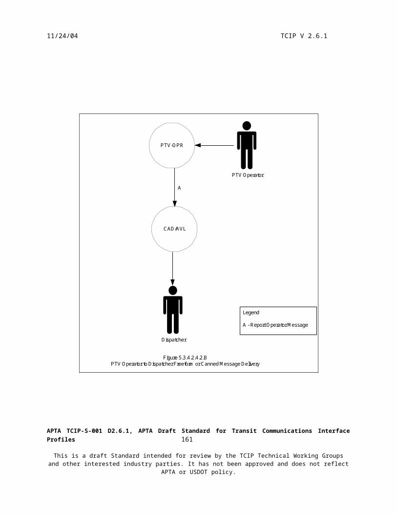
11/24/04 TCIP V 2.6.1
Schedule adherence data may be collected from a variety of sources, such as:o An Automatic Vehicle Location system collects on-time performance data in the form of actual
arrival and leave times at scheduled timepoints. Sometimes schedule adherence data are also collected by an APC system.
o A Transit Signal Priority system also collects on-time performance data.o The Incident Management system may provide information on certain operational trends that are
not readily apparent or understood from looking just at automated sources such as AVL or APC data.
Other sourceso Customer feedback from a Customer Information System may provide information on problem
areas or requested service improvements o Operator input in the form of service reports may be used in making schedule adjustments.o Error reports from systems and users of Scheduling data may identify the need for corrections or
revisions that should be included in the next release.
Figure 5.5.4.1 depicts the process of gathering data into the Scheduling System to use in the schedule writing process. Not all of these information flows will be used by all agencies and agencies may have other locally defined information flows that are used. For example, this figure implies actual running times being extracted from operating data by the DR, and provided to GIS, and the GIS in turn provides new scheduled running times to scheduling. Other agencies may analyze and re-plan running times in the scheduling system without involving the GIS.
APTA TCIP-S-001 D2.6.1, APTA Draft Standard for Transit Communications Interface Profiles 163
This is a draft Standard intended for review by the TCIP Technical Working Groups and other interested industry parties. It has not been approved and does not reflect APTA or USDOT policy.
11/24/04 TCIP V 2.6.1
SchedulingSystem(SCH)
GeographicalInformation
System(GIS)
TransitSecurity
(TS)
CAD/AVLSystem
CustomerServiceSystem(CSS)
Fare System(FS)
DataRepository
(DR)
PassengerCounting
(PC)
Figure 5.5.4.1Potential Data Gathering Information Flows for Schedule Writing with Data Repository
Legend
A - Subscribe Pattern List Subscribe Stoppoint List Subscribe Timepoint ListB - Subscribe Fleet Passenger DataC - Subscribe Adherence PerformanceD - Subscribe Fare Passenger DataE - Subscribe Service Change RequestF - Subscribe Incident Report HistoryG - Report Schedule Validation ErrorH - Subscribe Actual Running TimesI - Subscribe Running Times
1 - SchPatternList SchTimepointList SchStoppointList2 - CcFleetPassengerData3 - CcAdherencePerformance4 - FcPassenger Data5 - PiServiceChangeRequest6 - SchIncidentHistory7 - SchActualRunningTimes8 - SchRunningTimesList
* These data items may be maintained in thescheduling system rather than externally in theGIS, in which case these flows would not apply.** Extracted by the DR from unload data receivedfrom PTV's via GS.*** Extracted by FC from unload data receivedfrom PTVs via GRS.
GML maps
1*, 8*, A
*, I*
2, B
3**,
C**,
G
4***
, D**
* 5, E, G
6, F, G
6, F
7**, H**
5.5.4.2 Developing Scheduling Products
Schedule writing is the process of creating a route and defining the service that will operate that route. A route is defined by one or more patterns – the geographic paths over which trips travel. Patterns may contain many types of points and events, including timepoints, bus stops, transfer points, fare zone changes, destination sign changes,
APTA TCIP-S-001 D2.6.1, APTA Draft Standard for Transit Communications Interface Profiles 164
This is a draft Standard intended for review by the TCIP Technical Working Groups and other interested industry parties. It has not been approved and does not reflect APTA or USDOT policy.

11/24/04 TCIP V 2.6.1
transit signal priority triggers, operator road relief points, automated announcements to passengers and other messages to the operator.
Route Schedules define the scheduled trips on a route in both directions. Trips are defined in terms of the patterns they are to follow and the times that the vehicle is scheduled to arrive at (or depart from) timepoints within the pattern. Route Schedules reference patterns that define the movements of vehicles along a route. A pattern is defined as a sequence of pattern segments. Pattern segments in turn define the timepoints, stoppoints and layovers associated with the vehicles movement. A pattern may also define other events that are scheduled enroute (e.g. destination sign changes). Patterns and pattern segments can be shared by more than one trip. Timepoints define locations at which the PTV’s progress is measured against schedule. In addition to in-service, or revenue, trips – some agencies also schedule ‘dead head’ trips, garage transfer trips, and other trips for administrative purposes. Some agencies exclude administrative trips from the schedule.
Each trip in the route schedule, is defined not only by the pattern it follows, but by the scheduled times at timepoints for the PTV. Timepoints may be shared by more than one pattern or pattern segment. Transfers – Transfers define opportunities for transit passengers to switch from one PTV and trip to another – usually between PTVs operating on different routes. The transfers specified in this out put from the scheduling process generally do not include all available transfers, but are limited to a subset that the agency determines to be of particular interest. Transfers may be protected or unprotected. A protected transfer implies that the agency may hold the departing PTV to wait for the arriving PTV so that transferring passengers can make the connection. Agency policies limit the duration and circumstances of such holds. Transfers may also be intermodal (e.g. light rail or subway to bus or vice versa.)
The schedule may be distributed to other business systems at this stage of the development process (see section 5.5.4.3), as the definitions of the trips to be run and transfers to be made available to customers may be useful to other transit business systems. The schedule group can then work on the remainder of the scheduling products (see below) in parallel with work done in other areas using the new schedule (e.g. develop printed timetables).
Once schedules are written, the block building process combines trips into optimized vehicle assignments such that the number of PTVs and platform hours are minimized. A block, also known as a vehicle assignment, includes everything a PTV is assigned to do from the time it pulls out of the garage until it pulls in. Different vehicle types are assigned to specific trips or routes based on ridership requirements or other characteristics of the route. The block building process determines the amount of layover or recovery time that a PTV will have between scheduled revenue trips. This is also the process that identifies the deadhead trips that might be needed to move a PTV from one route to another so that all trips are operated efficiently.
Vehicle assignments (or “blocks”) defining the daily work assignment for vehicles are the output of the blocking process. Scheduling creates the work assignments but does not assign this work to individual vehicles. The term unbound indicates that specific vehicles have not been paired (bound) with the work assignments. The assignment of specific vehicles to blocks is the responsibility of the “Garage Management System”.
Run-cutting is the final step in the scheduling process, in which vehicle assignments are cut into optimized operator assignments. A short vehicle assignment may require just one operator, while longer vehicle assignments may require several operators throughout the day. Some pieces of work may be combined to create a split shift assignment for a guaranteed 8-hour day. The goal of the run-cutting process is to efficiently distribute the work so that overall costs are minimized given union contract rules, pay rates, work rules and management requirements.
Operator assignments (or “runs”) defining a regular set of operator work assignments are the output of the runcutting process. As with Vehicle Assignments, the Scheduling process creates the work assignments but does not assign the work to individual operators. The term “unbound” indicates that specific operators have not been paired with a run. Runs generally consist of a series of assigned trips, however some agencies end/begin runs mid-trip. Therefore runs may begin or end or switch to a different trip at any timepoint on any trip. Operator assignments may be collected into weekly groupings called rosters by the scheduling system and distributed to other business systems (e.g. Operator Assignment System). Some agencies conduct “a-la-carte picks” in which
APTA TCIP-S-001 D2.6.1, APTA Draft Standard for Transit Communications Interface Profiles 165
This is a draft Standard intended for review by the TCIP Technical Working Groups and other interested industry parties. It has not been approved and does not reflect APTA or USDOT policy.

11/24/04 TCIP V 2.6.1
operators pick their work assignments, based not on aggregated rosters, but instead on individual daily assignments. In such cases the roster is created by the OAS during the pick process rather than as part of the schedule development process.
The most significant variation to this phase is whether the Scheduling work group will use the vendor-provided GIS functions internal to the Scheduling system, or use a separate agency GIS, to create, edit and maintain the geographic data elements related to the schedule.
Even if an agency uses an external data repository for the subsequent schedule distribution process, schedule writers typically will use the database internal to the scheduling system to perform the functions of this phase.
5.5.4.3 Distributing Scheduling Products
This process is intended to ensure that all parts of the transit agency are working from the “same sheet of music” to deliver transit service. In other words, operators must be trained, assigned, and available to drive vehicles that are fueled, repaired and assigned, in time to operate the service that customers have been informed to expect to arrive on time. Errors or failures in this process can result in failures to deliver the service that customers have been led to expect.
The outputs from the Scheduling business processes are: Master Schedule Version – Defines the appropriate revisions of selected schedule products in terms of
effective date, updated time (includes all updates through a specified time), expiration date, and optionally version number. This allows agencies to publish a schedule, a ‘next’ schedule and row updates to artifacts related to either schedule. This can be important if a business system crashes and needs to obtain the current schedule for a restart, as well as for day to day schedule configuration management.
Route Schedule – Defines the scheduled transfers and trips on a route in both directions. Trips are defined in terms of the patterns they are to follow and the times that the PTV is scheduled to arrive at (or depart from) timepoints within the pattern. Each direction for each route a specifies pattern or sequence of patterns that trips on that route in that direction follow by default. Since not all trips follow the same pattern or pattern sequence, each trip contains an optional field that allows the default to be overridden on a trip by trip basis. The same data elements are used to define patterns for the default and override cases. Transfers define opportunities for transit passengers to switch from one PTV and trip to another – usually between PTVs operating on different routes. The transfers specified in this out put from the scheduling process generally do not include all available transfers, but are limited to a subset that the agency determines to be of particular interest. Transfers may be protected or unprotected. A protected transfer implies that the agency may hold the departing PTV to wait for the arriving PTV so that transferring passengers can make the connection. Agency policies limit the duration and circumstances of such holds. Transfers may also be intermodal (e.g. light rail or subway to bus or vice versa.)
Running Times - Running times define the scheduled time for a PTV to move from one timepoint to another. These may vary based on time of day, day of week, and other factors. Other business systems may require this information to predict arrival times, or for other purposes.
Patterns- Patterns define the movements of PTVs along a route. A pattern is defined as a sequence of pattern segments. Pattern segments in turn define the timepoints, stoppoints and way points associated with the PTV’s movement. A pattern may also define other event(s) that are schedule enroute (e.g. destination sign changes). Patterns and pattern segments can be shared by more than one trip.
Timepoints – Timepoints define locations at which the PTV’s progress is measured against schedule. Each trip in the route schedule, is defined not only by the pattern it follows, but by the scheduled times at timepoints for the PTV. Timepoints may be shared by more than one pattern or pattern segment.
APTA TCIP-S-001 D2.6.1, APTA Draft Standard for Transit Communications Interface Profiles 166
This is a draft Standard intended for review by the TCIP Technical Working Groups and other interested industry parties. It has not been approved and does not reflect APTA or USDOT policy.

11/24/04 TCIP V 2.6.1
Operator Assignments (unbound) – Operator assignments (or “runs”) define daily work assignments for PTV operators. A this stage in the process individual operators have not been paired (bound) with the work assignments, consequently the assignments are termed “unbound”. A run generally consists of a series of assigned trips, however some agencies end/begin runs mid-trip. TCIP accommodates this requirement by allowing a run to begin or end or switch to a different trip at any timepoint on any trip.
Vehicle Assignments (unbound) – Vehicle assignments (or “blocks”) define a daily work assignment for a PTV. At this stage in the process, specific PTVs have not been paired (bound) with the work assignments, consequently the assignments are termed “unbound”.
The schedule distribution may be directly to using business systems or to a Data Repository (DR). In the case of a Data Repository (DR), the schedule information may be transferred to the DR using subscription dialogs to ‘pull’ the information from the Scheduling System (SCH), using push dialogs to push the information from SCH to DR, or using file transfers based on the subscription or push messages. Figures 5.5.4.3 A & B depict these transfers to the DR.
SchedulingSystem(SCH)
DataRepository
(DR)
1, A
Legend
A - Subscribe Operator Assignments Subscribe Vehicle Assignments Subscribe Master Schedule Version Subscribe Route Schedule Subscribe Pattern List Subscribe Timepoint List Subscribe Running Times Subscribe Calendar Subscribe Roster
1 - SchOperatorAssignments SchVehicleAssignments SchMasterScheduleVersion SchRouteSchedule SchPatternList SchTimepointList SchRunningTimeList SchCalendar SchRoster
Figure 5.5.4.3.ASchedule Information Transfers to a Data Repository Based on Subscription Dailogs or File Transfers.
APTA TCIP-S-001 D2.6.1, APTA Draft Standard for Transit Communications Interface Profiles 167
This is a draft Standard intended for review by the TCIP Technical Working Groups and other interested industry parties. It has not been approved and does not reflect APTA or USDOT policy.

11/24/04 TCIP V 2.6.1
SchedulingSystem(SCH)
DataRepository
(DR)
1, A
Legend
A - Push Operator Assignments Push Vehicle Assignments Push Master Schedule Version Push Route Schedule Push Patterns Push Timepoints Push Running Times Push Calendar Push Roster
1 - SchPushOperatorAssignments SchPushVehicleAssignments SchPushMasterScheduleVersion SchPushRouteSchedule SchPushPatterns SchPushTimepoints SchPushCalendar SchPushRoster
Figure 5.5.4.3.BSchedule Information Transfer to a Data Repository Based on Push Dialogs or File Transfers.
Once the DR has the scheduling artifacts, it distributes those artifacts to business systems that require them. This may occur using subscription dialogs or related file transfers. Figure 5.5.4.3.C depicts this process.
APTA TCIP-S-001 D2.6.1, APTA Draft Standard for Transit Communications Interface Profiles 168
This is a draft Standard intended for review by the TCIP Technical Working Groups and other interested industry parties. It has not been approved and does not reflect APTA or USDOT policy.

11/24/04 TCIP V 2.6.1
Legend
A - Subscribe Operator Assignments Subscribe Roster B- Subscribe Vehicle Assignments C - Subscribe Master Schedule Version Subscribe Route Schedule Subscribe Pattern List Subscribe Timepoint ListD - Subscribe Stoppoint ListF - Subscribe Running TimesG -Subscribe CalendarH - Load Schedule
1 - SchOperatorAssignments SchRoster2 - SchVehicleAssignments3 - SchMasterScheduleVersion SchRouteSchedule SchPatternList SchTimepointList4 - CptStoppointList6 - SchRunningTimeList7 - SchCalendar8 - SchRouteScheduleFile SchPatternFile SchTimepointsFile SchCalendarFile CptStoppointsFile
DataRepository
(DR)
GarageServer(GS)
AssetManagement
System(AM)
OperatorAssignment
System(OAS)
CustomerServiceSystem(CSS)
AuthorizedBusinessSystem(ABS)
TravelerInformation
System(TRV)
GeographicalInformaiton
System(GIS)
PassengerCounting
(PC)
CAD/AVLSystem
Note:1. GS will either use schedule load, or subscriptions but not both.2. Schedule Distribution to PTVs is done by GS - see section 5.3.4.1
Figure 5.5.4.3.CSchedule Artifact Distribution by Data Repository
1, 2, 3, 7, 8, A, B, C, G, H
3, 4, 6, 7, C, D, F, G
3, 4, 6
, 7, C
, D, F
, G
1, 2
, 3, 4
, 6, 7
, A, B
, C, D
, F, G
3, 4
, 6, 7
, C, D
, F, G
1, 3, 7, A, C, G
2, 3, 7, B, C, G
3, 6, 7, C, F, G
3, 4, 6, 7, C, D, F, G
ExternalAgency
3, C
If the agency architecture does not include a DR, agencies may have individual business systems subscribe directly to SCH, or may employ file transfers from the Scheduling System to each business system or may have another business system act as the distributor. Figure 5.5.4.3.D depicts the case of the Scheduling System distributing schedules directly to business systems.
APTA TCIP-S-001 D2.6.1, APTA Draft Standard for Transit Communications Interface Profiles 169
This is a draft Standard intended for review by the TCIP Technical Working Groups and other interested industry parties. It has not been approved and does not reflect APTA or USDOT policy.

11/24/04 TCIP V 2.6.1
APTA TCIP-S-001 D2.6.1, APTA Draft Standard for Transit Communications Interface Profiles 170
This is a draft Standard intended for review by the TCIP Technical Working Groups and other interested industry parties. It has not been approved and does not reflect APTA or USDOT policy.

11/24/04 TCIP V 2.6.1
Legend
A - Subscribe Operator Assignments B- Subscribe Vehicle Assignments C - Subscribe Master Schedule Version Subscribe Route Schedule Subscribe Pattern List Subscribe Timepoint ListD - Subscribe Stoppoint ListF - Subscribe Running TimesG -Subscribe CalendarH - Load Schedule
1 - SchOperatorAssignments SchRoster2 - SchVehicleAssignments3 - SchMasterScheduleVersion SchRouteSchedule SchPatternList SchTimepointList4 - CptStoppointList6 - SchRunningTimeList7 - SchCalendar8 - SchRouteScheduleFile SchPatternFile SchTimepointsFile SchCalendarFile CptStoppointsFile
SchedulingSystem(SCH)
GarageServer(GS)
AssetManagement
System(AM)
OperatorAssignment
System(OAS)
CustomerServiceSystem(CSS)
AuthorizedBusinessSystem(ABS)
TravelerInformation
System(TRV)
GeographicalInformaiton
System(GIS)
PassengerCounting
(PC)
CAD/AVLSystem
Note:1. GS will either use schedule load, or subscriptions but not both.2. Schedule Distribution to PTVs is done by GS - see section 5.3.4.1
Figure 5.5.4.3.DSchedule Artifact Distribution Without Data Repository
1, 2, 3, 7, 8, A, B, C, G, H
3, 4, 6, 7, C, D, F, G
3, 4, 6
, 7, C
, D, F
, G
1, 2
, 3, 4
, 6, 7
, A, B
, C, D
, F, G
3, 4
, 6, 7
, C, D
, F, G
1, 3, 7, A, C, G
2, 3, 7, B, C, G
3, 6, 7, C, F, G
3, 4, 6, 7, C, D, F, G
ExternalAgency
3, C
In addition for the products produced by the scheduling system, transit agencies produce a plethora of derived products using the schedule. Some of these products are extracts from the schedule products, and some are produced by fusing schedule products together, or with other information.
The DR can be the focal point for the creation and distribution of derived products. Figure 5.5.4.3.E depicts the distribution of derived products by DR. Distribution flows for derived products without a DR are highly dependent on the agency architecture.
APTA TCIP-S-001 D2.6.1, APTA Draft Standard for Transit Communications Interface Profiles 171
This is a draft Standard intended for review by the TCIP Technical Working Groups and other interested industry parties. It has not been approved and does not reflect APTA or USDOT policy.

11/24/04 TCIP V 2.6.1
DataRepository
(DR)
GarageServer(GS)
AssetManagement
System(AM)
OperatorAssignment
System(OAS)
CustomerServiceSystem(CSS)
AuthorizedBusinessSystem(ABS)
TravelerInformation
System(TRV)
Legend
A - Push Vehicle AssignmentsB - Subscribe Pull In List Subscribe Pull Out List Subscribe Operator Assignments (bound) Subscribe Vehicle Assignments (bound)C - Push Roster Push Operator Assignments (bound)D - Subscribe Stop ServiceE - Subscribe Text TimetableG - Subscribe Roster
1 - SchPushVehicleAssignments2 - SchPullInList SchPullOutList SchOperatorAssignments SchVehicleAssignments3 - SchPushRoster SchPushOperatorAssignments4 - SchStopServiceList5 - PiTextTimetable6 - PiPushTextTimetable7 - SchPushRoster
Figure 5.5.4.3.EDistribution of Derived Products Using a Data Repository
AB
C D,E DF
G
The most significant architecture variation relevant to this phase is whether an agency distributes scheduling data directly from the scheduling system or uses an intermediate data repository.
APTA TCIP-S-001 D2.6.1, APTA Draft Standard for Transit Communications Interface Profiles 172
This is a draft Standard intended for review by the TCIP Technical Working Groups and other interested industry parties. It has not been approved and does not reflect APTA or USDOT policy.

11/24/04 TCIP V 2.6.1
5.6 Personnel Management and Assignments
5.6.1 Purpose of Personnel Management and Assignments
The Personnel Management and Assignments business process ensures that service-ready PTV operators, and other employees are available to provide and manage scheduled service, and assigns specific people to work assignments including qualified PTV operators to work assignments (runs) defined by the Scheduling System (SCH).
5.6.2 Overview
Schedule Operator Assignments (runs) are combined into rosters which define weekly groupings of work assignments. This combination may be performed by the Scheduling System and provided to the Operator Assignment System (OAS), or may be done as part of a pick process (see below).
In some agencies, union agreements govern a “pick” process by which PTV operators choose their work on a monthly or quarterly basis. The results of the pick process are a preliminary set of bindings between scheduled work and specific PTV operators expected to perform that work. The pick process also results in the production of extra lists which indicate what PTV operators are available for duty on each day that do not have work assigned. When the combination of runs into rosters is conducted as part of the pick process, it is known as an ‘a-la-carte pick’.
This business process also deals with changes to operator assignments due to operator unavailability (e.g. illness, leave), or changes due to incidents.
Some challenges and constraints related to this business process include: Union agreements and rules constrain agency policies and procedures. Changes to these agreements and rules
may impact agency software. Actual availability of operators changes from day to day requiring adjustments to planned assignments. Incidents and events occur to operators and PTVs after they are dispatched requiring assignments to be
changed.
5.6.3 Primary Architecture Component
The key architectural element for this business process is the Operator Assignment System (OAS). This business system manages the pick process as well as daily assignment changes. The Garage Server (GS) is also involved in providing these assignments to the PTVs.
5.6.4 Operator Assignment Processes
5.6.4.1 Operator Assignment Definition
The first step in the operator assignment process is the development of daily operator work assignments (runs) tied to the scheduled service. If the agency does not employ a-la-carte picks, the Scheduling System (SCH) will distribute these unbound assignments along with the corresponding rosters to the Operator Assignment System (OAS). Figure 5.6.4.1 depicts this process with and without a Data Repository (DR).
APTA TCIP-S-001 D2.6.1, APTA Draft Standard for Transit Communications Interface Profiles 173
This is a draft Standard intended for review by the TCIP Technical Working Groups and other interested industry parties. It has not been approved and does not reflect APTA or USDOT policy.

11/24/04 TCIP V 2.6.1
APTA TCIP-S-001 D2.6.1, APTA Draft Standard for Transit Communications Interface Profiles 174
This is a draft Standard intended for review by the TCIP Technical Working Groups and other interested industry parties. It has not been approved and does not reflect APTA or USDOT policy.

11/24/04 TCIP V 2.6.1
SchedulingSystem(SCH)
OperatorAssignment
System(OAS)
1, A
Legend
A - Push Operator Assignments (unbound) Push Roster (unbound) Subscribe Operator Assignments (unbound) Subscribe Roster
1 - SchPushOperatorAssignments SchPushRoster, or SchOperatorAssignments SchRoster
Figure 5.6.4.1.ADisribution of Unbound Operator Assignments Without a Data Repository (No A-la-Carte Pick)
SchedulingSystem(SCH)
OperatorAssignment
System(OAS)
DataRepository
(DR)
1, A
1, A
Figure 5.6.4.1.BDistribution of Unbound Operator Assignments With a Data Repository
APTA TCIP-S-001 D2.6.1, APTA Draft Standard for Transit Communications Interface Profiles 175
This is a draft Standard intended for review by the TCIP Technical Working Groups and other interested industry parties. It has not been approved and does not reflect APTA or USDOT policy.

11/24/04 TCIP V 2.6.1
5.6.4.2 Pick Process
Once the Operator Assignment System (OAS) has the unbound operator assignments and the rosters, it is possible to execute the pick. Normally the schedule and procedure of the pick is known will in advance. The pick process is usually related in some way to the seniority of PTV Operators and is tightly coupled with union agreements.
When the pick is completed, the Operator Assignment System (OAS) has the information necessary to produce a list of (preliminary) bound assignments for any given day. There preliminary bindings may be changed numerous times within the OAS between the time of the pick and the time of the next pick.
5.6.4.3 Distribution of Bound Assignments
The Operator Assignment System (OAS) on a daily basis provides the bound operator assignments to the Garage Server (GS). The Garage Server (GS) may fuse the bound operator assignments with the bound vehicle assignments received from the Asset Management System (AM). The Garage Server (GS) loads the bound assignments to the PTVs. Figure 5.6.4.3 depicts this process.
Note: Operator assignments are described here using a “push” approach to daily assignments. For a discussion of an alternative “pull” approach see section 5.3.4.1.
OperatorAssignment
System(OAS)
AssetManagement
(AM)
PTV-DATGarageServer(GS)
CAD/AVLSystem
1, C
2, D
1, C
2, D
A, B
Legend
A - Load Operator Assignments (bound)B - Load Vehicle Assignments (bound)C - Push Operator AssignmentsD - Push Vehicle AssignmentsE - Subscribe Unassigned VehiclesF - Subscribe Unassigned Operators
1 - SchPushOperatorAssignments2 - SchPushVehicleAssignments
Figure 5.6.4.3Distributing Bound Operator Assignments
SPV-DAT
DataRepository
C, F
D, E
C, F
D, E
5.6.4.4 Changes to Operator Assignments
Changes to operator assignments may be occasioned by operator unavailability, incidents or other reasons. If the change to the operator assignment occurs before the distribution of the bound assignments from the OAS to other business systems the change is made within the OAS.
APTA TCIP-S-001 D2.6.1, APTA Draft Standard for Transit Communications Interface Profiles 176
This is a draft Standard intended for review by the TCIP Technical Working Groups and other interested industry parties. It has not been approved and does not reflect APTA or USDOT policy.

11/24/04 TCIP V 2.6.1
If an assignment change occurs after the bound assignment is distributed to other business systems, then OAS updates the assignments to each impacted business system using the Command Change Assignments dialog. Sections 5.2.4 and 5.3.4 discuss this process in more detail.
APTA TCIP-S-001 D2.6.1, APTA Draft Standard for Transit Communications Interface Profiles 177
This is a draft Standard intended for review by the TCIP Technical Working Groups and other interested industry parties. It has not been approved and does not reflect APTA or USDOT policy.
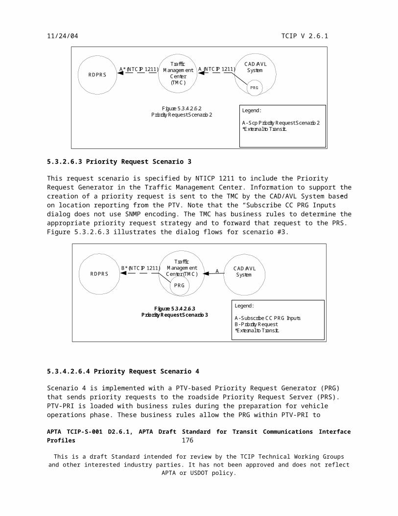
11/24/04 TCIP V 2.6.1
5.7 Asset Management
5.7.1 Purpose of the Asset Management Business Process
The Asset Management business process ensures that service-ready PTVs are available to provide scheduled service and assigns specific PTVs to work assignments (blocks) defined by the Scheduling System (SCH).
The Asset Management System (AM) maintains a history and schedule of PTV service. This provides the basis for maintenance planning, parts demand forecasts and vehicle availability planning, parts demand forecasts and vehicle availability planning. The Asset Management System also tracks PTV faults alarms and incidents or PTV service failures as inputs to the maintenance planning process.
The Asset Management System may also maintain the agency’s PTV inventory, or this function may be performed by the Data Repository (DR), or other agency Authorized Business System (ABS).
The following list summarizes the activities included in the Asset Management business process: Monitor vehicle mechanical health Diagnose defects Predict failures Monitor fuel and fluids consumption Manage vehicle configuration Track vehicle miles/hours/idle time/duty cycle Schedule vehicles for service and bind vehicles to assignments (Blocks and trips) (Vehicle assignment
policies may seek to balance miles and/or maintain a consistent pairing of specific vehicles with specific operators)
Schedule maintenance activities, vehicle inspections and servicing Manage spare parts inventory (typically included in Materials Management Subsystem) Manage maintenance work orders, technician assignments and maintenance personnel schedules Manage garage parking for revenue vehicles Manage tool inventory (typically included in Materials Management Subsystem) Monitor/calibrate/ and manage testing and shop equipment Performance management and Reporting
5.7.2 Overview of Asset Management
The Asset Management business process encompasses 11 areas. One of these areas (farebox vaulting) is discussed in section 5.4.4.4 (Revenue Reconciliation). The remaining 10 areas are:
Pull In Fuelling Cleaning/Washing Service/Inspection/Scheduled Maintenance Unscheduled Maintenance Overhaul/Contractor/Manufacturer Maintenance Garage Parking Management & Vehicle Assignments Pull Out En-route Synchronization/Calibration (May be included in fixed facilities management system)
The garage maintenance management and technician staff are the key organizational entities involved in this process. The key challenge in this area is to consistently and reliably provide clean, service-ready PTVs on a daily basis in adequate numbers and types to meet service requirements while maintaining a very low rate of in-service failures.
APTA TCIP-S-001 D2.6.1, APTA Draft Standard for Transit Communications Interface Profiles 178
This is a draft Standard intended for review by the TCIP Technical Working Groups and other interested industry parties. It has not been approved and does not reflect APTA or USDOT policy.

11/24/04 TCIP V 2.6.1
5.7.3 Primary Model Architecture Components
The central architectural component in the Asset Management business process is the Asset Management System (AM). AM maintains the vehicle maintenance records for both scheduled and unscheduled activities, as well as the vehicle assignments on a daily basis. AM may also provide tools for managing the parking of PTV’s in the garage area.
5.7.4 Asset Management Processes
5.7.4.1 PTV Pull In to Garage
This process deals with activities related to the PTV returning to the garage after a trip. The trip may be in-service, but may also be a ferry move, training trip etc.
The vehicle pull-in is reported by a supervisor or may be detected automatically. This report may be via a supervisor’s portable device or directly into the Garage Server (GS). The Garage Server (GS) reports the Pull-In to AM.
When the PTV enters the garage area, it may detect the availability of the wireless LAN. This triggers onboard entities to initiate data loads and unloads to the Garage Server (GS) and Garage Revenue Server (GRS). These loads and unloads are described in sections 5.3.4.1.1 (loading) and 5.3.4.4.3 (unloading).
Upon entering the garage area the operator may report defects concerning the vehicle, after which the operator will log off of the PTV, and may shut down the vehicle. These processes are illustrated in section 5.3.4.4.4.
The pull-in report and/or the inspection report may trigger AM to update parking and/or maintenance plans for the vehicle. Based on the plans for that vehicle, a technician or bolster may log onto and off of the vehicle for various purposes and/or may start up or shut off the vehicle and/or its onboard electronics. These logon/off and startup/shutdown events are handled in the same manner as operator initiated logon/logoff and startup/shutdown events (see sections 5.3.4.1.2, 5.3.4.1.3, 5.3.4.4.4). Note that when the VLU is started up, it triggers another attempt to load and unload data, so any startup may be the trigger for an update to loaded/unloaded data. Data is only loaded/unloaded if required.
5.7.4.2 Fuelling
This process may or may not occur daily, depending on agency fueling policies, fuel tank capacity, and daily fuel consumption. This process may be initiated routinely by transit staff, or be triggered by calculations of fuel and/or fluid requirements by AM.
The vehicle may be driven to the fueling area by the operator or by a hostler. Prior to or upon entering the fueling area, a set of agency defined safety checks are performed. Depending on the agency architecture, data loads/unloads may occur specifically in the fueling area, rather than at any location within the garage facility.
The actual fueling and fluid replenishment is conducted by the technician, and the amount of fuel and other fluids used is recorded in AM.AM may audit the fuel and fluids taken against an expected value based on vehicle type, mileage etc. AM may generate discrepancy reports for unusually high or low fluid/fuel consumption.
At the end of the fueling cycle a technician, inspector, or supervisor may be required by agency policy to conduct and record additional safety and/or leak checks, and an area inspection.
APTA TCIP-S-001 D2.6.1, APTA Draft Standard for Transit Communications Interface Profiles 179
This is a draft Standard intended for review by the TCIP Technical Working Groups and other interested industry parties. It has not been approved and does not reflect APTA or USDOT policy.

11/24/04 TCIP V 2.6.1
5.7.4.3 Cleaning
PTV cleaning normally occurs on an agency-specified periodic bases. It includes both interior and exterior vehicle cleaning. Additional unscheduled cleaning events may be inserted if the vehicle becomes excessively dirty, salt covered, etc. Agencies may have a daily minimal cleaning event (e.g. sweep out) for PTVs that do not receive a complete daily interior and exterior cleaning.
The PTV is pulled into a vacuum area and to a wash rack. Depending on agency facility design there may be a multistage process with a station for each stage of the process. At the end of the process a cleaner or supervisor inspects the PTV and records the results in the Asset Management System.
Some PTVs (e.g. commuter buses) have public toilet facilities onboard. Draining the septic tank for these PTVs and refilling the related expendable commodities (water, soap, etc) may be done in conjunction with the cleaning cycle, the fueling cycle or as an independent process.
5.7.4.4 Scheduled Service and Inspections
PTVs require periodic service and inspections. The Asset Management System (AM) monitors the intervals between service actions and schedules PTVs to receive service and inspections. When scheduled for service and inspection, AM generates a work order for the activity. A hostler, or a technician brings the PTV to a service bay, and the technician logs in the start time and vehicle ID for the periodic service.
AM provides the technician with an inspection/service checklist which may be customized based on: Vehicle type Time/mileage since last service Age of routinely replaced components Inspection reports provided by operator or supervisors
The technician performs the required service and inspection, and may enter tools or parts requests into AM. If the required actions cannot be completed due to lack of tools or parts, a deferred maintenance record maybe generated; otherwise the technician completes the service activity.
AM generates an update to the warranty and/or other maintenance records for the PTV, and if warranty-covered services where required may generate claims forms etc. AM generates a request for a supervisor or quality assurance inspection or the work.
The supervisor, or quality control inspector verifies the work and enters the results of the check into AM. AM updates the appropriate records for the vehicle.
Finally the vehicle is removed from the bus by the technician of hostler. If AM has parking management capabilities, it may provide instructions on where to move the vehicle to stage it for its next assignment.
5.7.4.5 Unscheduled Maintenance
Unscheduled maintenance occurs as a result of a manually, or automatically generated report of a vehicle fault, or out of tolerance condition. Manual reports are provided:
As a result of AM monitoring vehicle parameters on the PTV (Subscribe PTV Parameters) or, As a result of AM subscribing to health alarms for the PTV fleet (Subscribe Fleet Health Alarms) or, As a result of AM subscribing to health alarms from individual PTVs (Subscribe PTV Health Alarms)
Section 5.3.4.2.5 depicts automatically detected enroute reporting scenarios.
APTA TCIP-S-001 D2.6.1, APTA Draft Standard for Transit Communications Interface Profiles 180
This is a draft Standard intended for review by the TCIP Technical Working Groups and other interested industry parties. It has not been approved and does not reflect APTA or USDOT policy.

11/24/04 TCIP V 2.6.1
Once AM becomes aware of the problem, it updates the vehicle status (in-service/available for service/operable non-revenue only/ in operable). If the vehicle failed in-service, this event is managed as an incident as described in section 5.2. AM opens a workorder for the vehicle.
The vehicle at some point in time is scheduled to be brought in for service. A hostler or technician brings the vehicle into the bay, and the technician logs in the start time and vehicle ID for the unscheduled service.
AM generates a service/inspection checklist based on the reported fault, and possibly including other routine items to be inspected/repaired/replaced. The technician performs the required service and inspection, and may enter tools or parts requests into AM. If the required actions cannot be completed, a deferred maintenance record may be generated; otherwise the technician completes the service activity.
AM generates an update to the warranty and/or other maintenance records for the PTV, and if warranty-covered services where required may generate claims forms etc. AM generates a request for a supervisor or quality assurance inspection or the work.
The supervisor, or quality control inspector verifies the work and enters the results of the check into AM. AM updates the appropriate records for the vehicle.
Finally the vehicle is removed from the bay by the technician of hostler. If AM has parking management capabilities, it may provide instructions on where to move the vehicle to stage it for its next assignment.
5.7.4.6 Overhaul/Contactor/Manufacturer Maintenance
This process covers contractor or manufacturer performed maintenance. This is includes major maintenance actions such as recalls, overhauls, or other substantial upgrades.
This process begins with the generation of an overhaul or contractor request. This may be done manually, or recommended by AM software based on reliability software analyses. When the request is approved, the vehicle’s status is updated by a manager or technician in AM. The new status may be “out-of-service”, “transferred-central-shop”, “transferred-contractor”, “transferred-manufacturer” etc.
AM updates the vehicle’s maintenance records upon transferring the vehicle out and upon receiving it back. These updates may impact warranty records, major subassembly records (serial number change, initial mileage charge etc).
When the vehicle is returned, AM provides an inspection checklist for the supervisor or quality control inspector. The inspection checklist may include acceptance criteria, and may require acceptance testing, when the vehicle passes the inspection, the vehicle’s records are again updated and the vehicle returned to service.
5.7.4.7 Garage Parking Management & Vehicle Assignment
This process deals with the allocation of ready-for-service vehicles to vehicle work assignments, and the allocation or vehicles to parking spaces in the vicinity of the garage. Asset Management Systems may not provide all of the functionality described here, or the functionality may be supplied as separate modules or subsystems within the Asset Management framework.
AM receives the vehicle work assignments (blocks) from the Data Repository (DR) or the Scheduling System (SCH). In addition AM maintains an inventory of the vehicles along with their current and scheduled maintenance
APTA TCIP-S-001 D2.6.1, APTA Draft Standard for Transit Communications Interface Profiles 181
This is a draft Standard intended for review by the TCIP Technical Working Groups and other interested industry parties. It has not been approved and does not reflect APTA or USDOT policy.

11/24/04 TCIP V 2.6.1
status. If AM contains a parking management component, then AM also maintains a schedule of parking space allocations for PTVs that are ready for service, as well as for vehicles that are awaiting service, inspections, fueling, cleaning etc.
Based on the blocks of work scheduled for the coming day, and the expected set of service ready vehicles, AM establishes preliminary vehicle assignments for the coming day’s work. Similarly other vehicles may be assigned to maintenance for all or part of the coming day. Vehicles may also be assigned to queues within AM for cleaning a fueling.
Based on the assignments and determinations made in the previous paragraph, AM establishes parking space assignments for vehicles that will facilitate efficient pullouts and efficient hostling of vehicles for cleaning, fueling, and service.
In advance of the morning pull outs, AM provides the daily bound vehicle assignments, and pull outs to other business systems, and specifically to the Garage Server. The pullout lists contain parking space assignments indicating where the vehicle (hopefully) will be found.
In the Garage Server (GS) the pull out list provided by AM is combined with information received from the Operator Assignment System (OAS). This allows GS to provide a pullout list to the supervisor in charge of pullouts that combines the vehicleID, parking location, operator, pullout time and pullout trip (initial trip). This information facilitates the effective management of the pull-out process. Figure 5.7.4.7.A depicts these processes.
GarageServer (GS)
AssetManagement
(AM)
DataRepository
(DR)
OperatorAssignment
System(OAS)
SPV-DAT
Legend
A - Subscribe Vehicle Assignments (unbound)B - Load Vehicle Assignments (bound) Subscribe Pull Out List (vehicles specified)C - Load Operator Assignments (bound) Subscribe Pull Out List (operators specified)D - Subscribe Pull Out List (operators and vehicles specified)
1 - SchVehicleAssignmentList2 - SchVehicleAssignmentsFile (bound) SchPullOutList (vehicles specified)3 - SchOperatorAssignmentsFile (bound) SchPullOutList (operators specified)
Figure 5.7.4.7.APull Out Information Fusion During the Parking Management and Vehicle Assignment Process
1, A
2, B 3, C
D
At the end of the day, based on the preliminary schedule for activities for the following day – AM provides pull-in information to the Garage Server for use by the supervisor managing pull-ins. These lists contain parking space assignments for vehicles based on whether they are going to be fueled, cleaned, serviced or returned to service the following day. Figure 5.7.4.7.B depicts this process.
APTA TCIP-S-001 D2.6.1, APTA Draft Standard for Transit Communications Interface Profiles 182
This is a draft Standard intended for review by the TCIP Technical Working Groups and other interested industry parties. It has not been approved and does not reflect APTA or USDOT policy.

11/24/04 TCIP V 2.6.1
GarageServer (GS)
AssetManagement
(AM)
DataRepository
(DR)
SPV-DAT
1, A
2, B
B
Legend
A - Subscribe Vehicle Assignments (unbound)B - Subscribe Pull-In List (vehicles specified)
1 - SchVehicleAssignmentList2 - SchVehicleAssignmentsFile SchPullInList
Figure 5.7.4.7.BPull-In Information During Parking Mangement and Vehicle Assignment Process
5.7.4.8 Pull Out Process
The pull out process involves getting the ready-for-service assigned operator paired with the ready-for-service assigned PTV and having them leave the garage at the appointed time. The operator reports to a supervisor who verifies that the operator is ready for service, and then to the PTV. The operator inspects the PTV, starts it and logs on to the PTV. If the PTV starts up in wireless LAN coverage, onboard components interact with the Garage Server (GS), and the Garage Revenue server (GRS) to verify that there are no new or updated files to load.
The data loading process is described in section 5.3.4.1.1. Vehicle startup is described in section 5.3.4.1.2. The Operator sign-on and inspection process is described in section 5.3.4.1.3.
Once the operator and PTV are ready to go and the scheduled pull out time occurs, the supervisor reports the pull out to the Garage Server (GS) using the SPV or directly to the Garage Server (GS). Depending on the agency architecture, pullouts may be detected automatically by the CAD/AVL System and reported to the Garage Server. Section 5.3.4.1.4 describes this process.
Based on the reported pull out, AM updates the parking allocation (frees the assigned space) and status of the PTV (in-service).
5.7.4.9 En Route Failures
Section 5.7.4.5 discussed unscheduled maintenance. This section describes a special case of unscheduled maintenance – an en route failure. PTV faults and failures enroute include amenity failures (e.g. wheelchair lift, air conditioning), electronics faults and failures (e.g. VLU, radio), drivetrain faults and failures (e.g. engine, transmission), and safety equipment faults and failures (e.g. mirrors, tires, brakes).
Enroute failures may constitute an incident. The incident management process is described in section 5.2. This section focuses on the process for recovering and repairing the PTV.
APTA TCIP-S-001 D2.6.1, APTA Draft Standard for Transit Communications Interface Profiles 183
This is a draft Standard intended for review by the TCIP Technical Working Groups and other interested industry parties. It has not been approved and does not reflect APTA or USDOT policy.

11/24/04 TCIP V 2.6.1
Notification of an enroute failure may occur:
Via voice radio from the operator to the dispatcher, with a dispatcher call or email to notify the garage, Via text messaging from the operator to the dispatcher, with a dispatcher call to the garage. Via automatic health alarm or vehicle parameter reporting.
Agency policy and physical constraints govern the reaction to an enroute failure. Failures that involve severe safety problems (e.g. loss of brakes) or inability to move under the PTVs own power normally result in the vehicle being towed back to the garage for repairs. Other less severe, scenarios may allow for the PTV to discharge passengers and proceed on its own power to the garage. Even less severe scenarios may allow the PTV to remain in-service.
If the PTV requires immediate attention, a maintainer is dispatched via voice or via the Asset Management System and the TMV. Transit Management may elect to send a new PTV and an ‘extra’ list operator to pick up discharged passengers, or to take on the faulty PTV’s assigned work. If the replacement PTV is not assigned pick up the discharged passengers, it may proceed to a timepoint further along the faulty PTV’s trip, or to the start point for the next assigned trip.
AM processing of the information related to the failure is described in section 5.7.4.5. Figure 5.7.4.9 illustrates information flows related to EnRoute Failures.
APTA TCIP-S-001 D2.6.1, APTA Draft Standard for Transit Communications Interface Profiles 184
This is a draft Standard intended for review by the TCIP Technical Working Groups and other interested industry parties. It has not been approved and does not reflect APTA or USDOT policy.

11/24/04 TCIP V 2.6.1
GarageServer (GS)
AssetManagement
(AM)
GarageServer (GS)
CAD/AVLPTV-DAT
(replacementPTV)
GarageServer (GS)
Garage Supervisor* Field Technician(e.g. wrecker driver)
B
C
A **
A ***
A **** A ****
Dispatcher
PTV Operator
Legend
A - Command Change AssignmentsB - Command Dispatch Incident Response Report Work Order AssignmentC - Report Work Order Update* May be more than one person involved toassign new vehicle and operator** Updates vehicle*** Updates operator**** Updates vehicle and operator
Figure 5.7.4.9Possible Response Scenario to En Route PTV FailureVerbal
Notice
5.7.4.10 Synchronization/Calibration
The Synchronization and calibration process ensures that instruments and equipment used by technicians remains within prescribed tolerances, allowing it to be used for its prescribed purpose. The Asset Management System (AM) maintains an inventory of devices/equipment that requires periodic calibration or synchronization. Associated with each type of item or equipment requiring calibration/synchronization, AM maintains a file describing the required protocols for calibrating/synchronizing the device/equipment. These protocols may include procedures, drawings, and verification test procedures.
For devices and equipment requiring time synchronization, AM may maintain configuration files recording time delays and required offsets. For example in an equipment clock is to be set, and the time to send a message to the device and have it processed is 30 milliseconds, then a time set command should be sent to the device with a time 30 ms in the future. Similarly in verifying that the time is set correctly, the latency from the time the clock is read in the device being synchronized to the time it is compared with the reference clock must be considered.
APTA TCIP-S-001 D2.6.1, APTA Draft Standard for Transit Communications Interface Profiles 185
This is a draft Standard intended for review by the TCIP Technical Working Groups and other interested industry parties. It has not been approved and does not reflect APTA or USDOT policy.

11/24/04 TCIP V 2.6.1
AM also maintains a schedule of calibration and synchronization due dates/times and notifies technicians of devices equipment schedule for calibration or synchronization. Performance of calibration and synchronization activities by technicians are reported to AM and logged, enabling AM to calculate the next required calibration or synchronization.
APTA TCIP-S-001 D2.6.1, APTA Draft Standard for Transit Communications Interface Profiles 186
This is a draft Standard intended for review by the TCIP Technical Working Groups and other interested industry parties. It has not been approved and does not reflect APTA or USDOT policy.

11/24/04 TCIP V 2.6.1
5.8 Customer Information
5.8.1 Purpose of Customer Information Business Process
The Customer Communications Business Process deals with all aspects of communicating with transit customers. This includes assisting customers in determining the availability of transit services, providing transit literature (e.g. maps, guides for the handicapped) notifying the status of service, providing itineraries and providing customers with information while on the transit agency’s property. It also includes managing persistent information about customers and collecting, and processing information necessary to investigate and resolve customer complaints.
5.8.2 Overview of Customer Information Business Process
The key people in the Customer Information business process are the customers themselves and the customer service representatives. Customers are the focus of each phase of this process, as the process exists to provide them useful information. Customers in this section are variously referred to as “customers” at any stage in the process, or “travelers” while in the transit property but not on a PTV, and “passengers” while boarding/alighting or onboard a PTV.
Customer Service Representatives may interact with customers via telephone at any stage of the journey. Customer Service may also initiate announcements and/or displayed messages on signs on PTVs or at stoppoints.
The customer information business process can be broken into several processes, based on the status of a customer’s journey:
The Pretrip Planning Process provides support to a customer planning to make a journey involving public transit. In many cases this requires information to be provided to the customer at their home or work location, however because plans may change enroute it may also support replanning at any stage in a journey.
The Station/Stop Process provides information to customers (travelers) while they are at a transit station or stoppoint. The most prevalent information in this phase is real-time service information.
The Passenger Process provides information to customers (passengers) while they are onboard a PTV. The most prevalent information in this phase is real time information about the PTV’s progress (e.g. next stop announcements).
The Ongoing Process provides information at times and locations independent of the customer’s actual or planned travel. This includes information related to compliant resolution, maintenance of customer profiles, and event-driven service information distribution.
Schedule, facilities, and map data are assumed to be stored in the Traveler Information System (TRV), and in the Customer Service System (CSS). The transfer of schedule information is discussed in section 5.5. The transfer of map data (in addition to the map information included with the schedule) is discussed in section 5.10. Figure 5.8.2 A&B depict the transfer of schedule, facilities, and map data to the TRV and CSS.
The current state of customer information varies widely among agencies. Some agencies have only customer service telephone support and printed materials, while others have begun implementing real-time information via
APTA TCIP-S-001 D2.6.1, APTA Draft Standard for Transit Communications Interface Profiles 187
This is a draft Standard intended for review by the TCIP Technical Working Groups and other interested industry parties. It has not been approved and does not reflect APTA or USDOT policy.

11/24/04 TCIP V 2.6.1
kiosks, web pages, PDAs etc. Some stoppoints, usually in high-density areas, are equipped with automated next bus information.
The emergence of low-cost solar powered wireless signs may begin to allow next bus information to be available at a larger number of locations in the future. In the meantime, the availability of capital and operating funds constrains the deployment to low-density locations.
TravelerInformation
System(TRV)
CustomerServiceSystem(CSS)
DataRepository
(DR)
1, 2, A, B, C
GML Maps
1, 2, A, B, CGML Maps
Legend
A - Subscribe Master Schedule Version Subscribe Route Schedule Subscribe Timepoint List Subscribe Pattern ListB - Subscribe Landmarks List Subscribe Stoppoints List Subscribe Facilities Subscribe Shelters Subscribe Transfer Cluster List Subscribe AmenitiesC - Subscribe Available Mailings
1 - SchMasterScheduleVersion SchRouteSchedule SchTimepointList SchPatternList2 - PiLandmarkList CptStoppointList CptTransitFacilities CptShelterList CptTransferClusterList
Figure 5.8.2.ATransfer of Information to TRV and CSS with Data Repository
GIS
GM
L M
aps
APTA TCIP-S-001 D2.6.1, APTA Draft Standard for Transit Communications Interface Profiles 188
This is a draft Standard intended for review by the TCIP Technical Working Groups and other interested industry parties. It has not been approved and does not reflect APTA or USDOT policy.

11/24/04 TCIP V 2.6.1
TravelerInformation
System(TRV)
CustomerServiceSystem(CSS)
Legend
A - Subscribe Master Schedule Version Subscribe Route Schedule Subscribe Timepoint List Subscribe Pattern ListB - Subscribe Landmarks Subscribe Stoppoints List Subscribe Facilities Subscribe Shelters Subscribe Transfer Cluster List Subscribe AmenitiesC - Subscribe Available Mailings
1 - SchMasterScheduleVersion SchRouteSchedule SchTimepointList SchPatternList2 - PiLandmarkList CptStoppointList CptTransitFacilities CptShelterList CptTransferClusterList
GIS
Scheduling(SCH)
GML Maps
GML Maps
A
B
CA
B
Figure 5.8.2.BTransfer of Information to TRV and CSS Without Data Repository
5.8.3 Primary Model Architecture Component Roles in Customer Information
Customer Communications are primarily supported by two model architecture business systems: Customer Service Systems (CSS) and Traveler Information Systems (TRV). These systems may be organized and/or named differently individual agency architectures.Customer Service systems support transit agency customer interactions via call centers and mail including:
Itinerary creation for customer service call takers Mailing management for printed material Customer information profile management Complaint management and resolution Timetable creation Trip duration estimates based on scheduled running times Service bulletin creation and dissemination Lost and found
Traveler Information Systems (TRV) support online interactions with customers via Passenger Information Displays, Traveler Internet Appliances, Kiosks, and Information Service Providers (ISP). Travelers can obtain the following via Internet Appliances, Kiosks, and ISPs:
Nearest Transit service and parking information Transit Itineraries and Fares Landmark Locations Text timetables Stoppoint shelter and amenity information Transfer Opportunities Service Bulletins Maps
The TRV and CSS obtain information from a variety of sources. Some of this information is obtained in advance of a customer’s need (e.g. schedules) and used repeatedly until superceded. Other information may be queried for on an as-needed basis (e.g. itineraries), or be provided on an ongoing basis using a persistent event driven or periodic subscription (e.g. next bus information).
APTA TCIP-S-001 D2.6.1, APTA Draft Standard for Transit Communications Interface Profiles 189
This is a draft Standard intended for review by the TCIP Technical Working Groups and other interested industry parties. It has not been approved and does not reflect APTA or USDOT policy.

11/24/04 TCIP V 2.6.1
Agencies can provide a variety of information to customers via stoppoint and PTV-based Passenger Information Displays which may provide audible as well as visual announcements including:
Next bus information at stoppoint Next stop information on PTVs Route and Destination information on PTVs Advertising and public service announcements on PTVs or stoppoints
Either the Traveler Information System (TRV) or Customer Service System (CSS) may serve as an Itinerary Generator for the other, or each may have its own internal itinerary generator. The CSS creates timetables from the schedule and provides those to the TRV. The TRV and/or the CSS may communicate with external Advanced Traveler Information Systems (ATIS) using SAE J2354 to obtain multimodal itineraries, itineraries including other transit agencies, weather information, etc, or to provide transit itineraries to external ATIS.
The TRV and CSS are provided fares for transit itineraries by the Fare System, and are provided on demand service status information by the CAD/AVL System. The CAD/AVL System also provides stoppoint ETA information which allows the TRV to provide next bus information at stoppoints. The CAD/AVL System provides service bulletins to CSS directly or via the Data Repository, similarly the Scheduling/Blocking/Runcutting System provides schedule information directly to CSS and TRV or via a Data Repository.
The CSS supports complaint resolution processes. Complaint investigations may require the investigator to review logs of vehicle movements from the CAD/AVL System, logs of operating data from PTVs or video images collected by cameras in PTVs or PTSFs and stored for later use.
Customer inquiries may use a variety of mechanisms to specify locations- particularly origins and destinations. Since customers generally do not know the latitude/longitude of their origin, destination or present location, the Subscribe Point Conversion dialog allows a business system to subscribe to translations of addresses, landmark names, etc. to latitude/longitude from another business system.
Customer Service Systems (CSS) and Traveler Information Systems (TRV) generate substantial quantities of important information on usage of transit transportation services, as well as on customer support and information service. This information is logged within these business systems and may be used for analyses of usage patterns etc. TCIP 2.6 does not standardize the format of these logs, or their transfer, however.
5.8.4 Customer Information Constituent Processes
5.8.4.1 Customer Information Pretrip Planning Process
In the planning process the customer has determined that he/she may be making a journey or journeys involving transit. The journey may be imminent or some time in the future, it may be a one time occurrence, or a new planned commuting pattern.
During the planning process, the customer will generally need information on service availability at the time of the planned trip. If the customer is unfamiliar with the transit system, they may start by asking for stoppoint locations near their origin and destination. They may need information on the availability of parking, shelters, handicap accessibility, or other amenities at the stoppoints of interest. The customer will usually want to know the fare, and the schedule for service at the stoppoints of interest around the expected travel time. Additionally, if the trip involves transfers, the customer may want information related to transfer opportunities, transfer clusters, transfer times, etc.
The communications with the customer may take the form of a series of questions or queries, or the customer may prefer to submit a request to have a complete itinerary created, and receive back a completed itinerary or series of alternative itineraries. These itineraries may also include maps. In cases where the journey is not imminent, the customer may want information mailed to them to support their own planning efforts. The list of available
APTA TCIP-S-001 D2.6.1, APTA Draft Standard for Transit Communications Interface Profiles 190
This is a draft Standard intended for review by the TCIP Technical Working Groups and other interested industry parties. It has not been approved and does not reflect APTA or USDOT policy.

11/24/04 TCIP V 2.6.1
mailings can be transferred from the data repository to the CSS at this time as well (if the list is not maintained in the CSS itself).
If the customer’s interaction is online, through an ISP, kiosk, or Internet appliance, the required information is provided by the Traveler Information System (TRV). If the customer calls the customer service telephone support service the required information is provided by the Customer Service System (CSS), usually based on information previously obtained from other business systems.
Individual agencies may implement a number of variations of the model architecture, including but not limited to: Implementation with or without a data repository Combining the TRV and CSS into a single business system, or segmenting the functionality of these
systems differently. Use of the GIS Data Repository or other Authorized Business System as the source of stoppoint,
landmark, point conversion or other information.
5.8.4.1.1 Itinerary Generation
Itinerary requests may originate from kiosks, internet appliance, Interactive Voice Response (IVR) system (e.g. 511 system) or other external (to the transit agency) business systems. The Traveler Information System (TRV) accepts these requests as TCIP messages or as SAE J2354 ATIS messages. Note that TCIP messages act as a container for an ATIS message – so the data is easily exchangeable with and without the TCIP container message.
Itinerary requests may also come by telephone to the Customer Service Call Center and be entered into the Customer Service System (CSS) by the customer service call taker. For illustrative purposes, we assume that itinerary generation is done in the Traveler Information System (TRV).
The TRV may be able to create an itinerary based solely on information it has stored internally, however it may also need to obtain information from other sources, such as the TRV from another transit agency, or external ATIS, or ISPs supporting other modes (taxi, highway, air transport).
The itinerary generation process may provide no itinerary due to an invalid request, or may return multiple alternative itineraries that meet the requirements in the request. Real-time information (e.g. weather) may be associated with the itinerary if the request is made with an intended travel time in the near future. Maps of the itinerary route may be provided with the itinerary.
Fares associated with the itinerary may be calculated by the Traveler Information System (TRV) if it has been loaded with the agency’s fare policies. If the agency architecture does not include transferring fare policies to TRV, then itinerary fares may be obtained on an itinerary-by-itinerary basis from the Fare System. This scenario is illustrated in Figure 5.8.4.1.1.
Similarly to fares, the TRV may have the capability to render a map for an itinerary, or the TRV may be reliant on the GIS to create a custom map on an itinerary-by-itinerary basis. The latter scenario is illustrated in Figure 5.8.4.1.1.
APTA TCIP-S-001 D2.6.1, APTA Draft Standard for Transit Communications Interface Profiles 191
This is a draft Standard intended for review by the TCIP Technical Working Groups and other interested industry parties. It has not been approved and does not reflect APTA or USDOT policy.
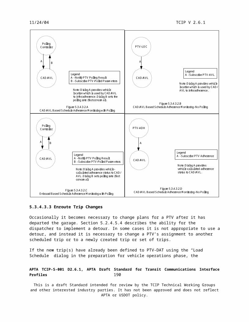
11/24/04 TCIP V 2.6.1
ExternalATIS
TravelerInformation
System(TRV)
ExternalATIS
OtherTransitAgency(TRV)
InformationServiceProvider
(ISP)
Fare System
OtherTransitAgency(TRV)
InformationServiceProvider
(ISP)
InternetDevice
(e.g. PDA)
Kiosk
CustomerServiceSystem(CSS)
Traveler
Voice
Traveler
Traveler
Customer ServiceCall Taker
Itinerary Requesters Information Sources for TRV
Legend
A - Subscribe Itinerary ListB - Subscribe Itinerary FareC - Subscribe Itinerary Map
Figure 5.8.4.1.1Itinerary Generation Alternative Information Flows
A
A
A
A
A
A
A
B
SAE ATIS Messages
SAE
ATIS
Mes
sage
s
SAE ATIS
Mes
sage
s
SAE ATIS Messages
GIS
C
5.8.4.1.2 Other Planning Data
Travelers may also need other information in planning their journey. This information might include: Determination of the nearest transit stop to an origin or destination of a trip. Determination of the landmarks in a vicinity e.g. near a transit stop. Determination as to whether parking is available at a transit stop.
APTA TCIP-S-001 D2.6.1, APTA Draft Standard for Transit Communications Interface Profiles 192
This is a draft Standard intended for review by the TCIP Technical Working Groups and other interested industry parties. It has not been approved and does not reflect APTA or USDOT policy.

11/24/04 TCIP V 2.6.1
Determination as to whether a shelter or other amenity is available at a transit stop. Obtaining a text (printable) timetable for a route. Determination of the current or planned service bulletins in effect. Information about service detours in effect.
Based on local policy, related information may be included with the responses to these queries. For example, a request for the nearest stop to a location of landmark might automatically return service bulletins in effect near the stop(s) and parking information for the stop(s) identified.
Agencies may elect not to report detours in effect to TRV and CSS, but instead to include this information only in the form of service bulletins, however both information flows are included in Figure 5.8.4.1.2.
Figure 5.8.4.1.2 depicts the information flows for responding to these queries.
OtherTransitAgency(TRV)
InformationServiceProvider
(ISP)
InternetDevice
(e.g. PDA)
Kiosk
CustomerServiceSystem(CSS)
Traveler
Voice
Traveler
Traveler
Customer ServiceCall Taker
Itinerary Requesters
TravelerInformation
System(TRV)
CAD/AVLSystem
CustomerServiceSystem(CSS)
1, A
1, AB, C
B, C
B, C
B, C
2, B
Legend
A - Subscribe Service Bulletin List Report Detour Report Cancel DetourB - Subscribe Text TimetableC - Subscribe Nearest Stop List Subscribe Stop Point Parking Subscribe Landmarks List Subscribe Amenitites Subscribe Shelters
1 - PiServiceBulletinList2 - PiTextTimetable
Figure 5.8.4.1.2Distribution of Other Planning Data
APTA TCIP-S-001 D2.6.1, APTA Draft Standard for Transit Communications Interface Profiles 193
This is a draft Standard intended for review by the TCIP Technical Working Groups and other interested industry parties. It has not been approved and does not reflect APTA or USDOT policy.

11/24/04 TCIP V 2.6.1
5.8.4.1.3 Printed Planning Material
Many transit agencies maintain hardcopy printed materials (maps, timetables, etc.) for use by their customers. Customers usually can pick these materials up at designated transit agency locations. Customer service call takers may be able to mail these materials to customers upon request. Customers may also be able to order these materials online or via a kiosk.
The system that manages the mailing process may be the Customer Service System (CSS), or another Authorized Business system. The list of available mailing may be maintained by the CSS, another Authorized Business System (ABS), or the Data Repository. For illustrative purposes we assume a separate ABS-Mailing system and that the list of available mailings is maintained in the Data Repository (DR).
Figure 5.8.4.1.3 depicts the mailing process.
Kiosk
Traveler
Voice
Traveler
Customer Service
TravelerInformation
System(TRV)
InternetAppliance
DataRepository
(DR)
CustomerServiceSystem(CSS)
AuthorizedBusinessSystem -mailing
Web Page
Web Page
B
B
1, A
1, A
1, A Mailing Materials
Traveler
Legend
A - Subscribe Available MailingsB - Command Send Mailing1 - PiMailingList
Figure 5.8.4.1.3Printed Mailing Materials Processing
5.8.4.2 Customer Information-Station/Stop Process
Most customer journeys that include transit involve passage through a transit center, station or stoppoint. This process involves communications with travelers while they are at or in one of these facilities.
Stoppoints may be as simple as a sign on the side of the road, or may be elaborate multimodal facilities. All stoppoints have provisions for displaying static information of the stoppoint location which may include servicing routes and timetable information. Some facilities will have provisions to communicate variable information to the customer using dynamic message signs or public address announcements.
APTA TCIP-S-001 D2.6.1, APTA Draft Standard for Transit Communications Interface Profiles 194
This is a draft Standard intended for review by the TCIP Technical Working Groups and other interested industry parties. It has not been approved and does not reflect APTA or USDOT policy.

11/24/04 TCIP V 2.6.1
The most common variable information to be provided at a stoppoint is next bus information. In some cases next bus information may be accompanied by service bulletins, special announcements, advertising and other agency-defined information. Agencies may provide the capability for live announcers to initiate audio and/or visual announcements.
TCIP does not define the messaging to control the announcements or message displays at stoppoints. TCIP does, however, provide the capability to convey next bus arrival information and service bulletins which may be used by TRV in operating these services.
TCIP provides the ability to query service status at a stop (e.g. next bus eta, schedule deviation) from a kiosk or Internet appliance.
Figure 5.8.4.2 A, B & C depict the Customer Information Station/Stop Process TCIP information flows.
APTA TCIP-S-001 D2.6.1, APTA Draft Standard for Transit Communications Interface Profiles 195
This is a draft Standard intended for review by the TCIP Technical Working Groups and other interested industry parties. It has not been approved and does not reflect APTA or USDOT policy.

11/24/04 TCIP V 2.6.1
Announcer
TravelerInformation
System(TRV)
PTSF-ANNStoppoint Sign(s)
Stoppoint Public Address System
LegendVendor Specified
Figure 5.3.4.2.AAnnouncer Triggered and Automated-Station/Stoppoint Announcements
CAD/AVLSystem
PTSF-ANNStoppoint Sign(s)
Stoppoint Public Address System
Legend
A - Subscribe Stoppoint ETAVendor Specified
A
Figure 5.3.4.2.BNext Bus Announcements at Stations/Stoppoints
CustomerServiceSystem(CSS)
Traveler
Voice
Customer ServiceCall Taker
InternetDevice
(e.g. PDA)
Kiosk
Traveler
Traveler
TravelerInformation
System(TRV)
CAD/AVLSystem
A
A
AA
Legend
A - Subscribe Service Status
Figure 5.8.4.2.CService Status Queries for Travelers
Note: One subscriptionbetween TRV and CAD/AVLcan support many subscribersat various stoppoints.
APTA TCIP-S-001 D2.6.1, APTA Draft Standard for Transit Communications Interface Profiles 196
This is a draft Standard intended for review by the TCIP Technical Working Groups and other interested industry parties. It has not been approved and does not reflect APTA or USDOT policy.

11/24/04 TCIP V 2.6.1
5.8.4.3 Customer Information – Passenger Process
The Customer Information Passenger Process involves the provision of information to a customer while they are onboard – or in some cases boarding/alighting a PTV. Key information to be provided includes Route Id, Destination, Express/Local information, Stop Announcements, Landmark Announcements, Enroute Announcements (including possibly fare zone boundary announcements).
Route, Destination, and Express/Local information are generally provided on destination signs, and possibly on other signs on other parts of the PTV as well. Stop announcements and other enroute announcements may be made by the driver or automatically, and may be accompanied by messages on Passenger Information Displays on the PTVs. Additionally, in some transit agencies, the dispatcher has the capability to remotely make live or canned announcement on the bus using the radio system.
Announcements, text messages destination sign messages and rules, and event-based announcements are loaded to the PTV (PTV-ANN) during the preparation for vehicle operations. This process is described in section 5.3.4.1.1.
Figure 5.8.4.3 A-E depicts the TCIP Information flows for the Passenger Phase of the Customer Information Business Process.
APTA TCIP-S-001 D2.6.1, APTA Draft Standard for Transit Communications Interface Profiles 197
This is a draft Standard intended for review by the TCIP Technical Working Groups and other interested industry parties. It has not been approved and does not reflect APTA or USDOT policy.

11/24/04 TCIP V 2.6.1
PTV-DAT PTV-ANNPassenger
PID(s)
Destination SignLegend
A - Notify Start of TripVendor/Agency Defined
Figure 5.8.4.3.APassenger Phase Start of Trip Information Flows
PTV-LOC PTV-ANN
Passenger
PID(s)
Destination Sign
Legend
A - Subscribe Onboard LocationVendor/Agency DefinedFigure 5.8.4.3.B
Passenger Phase Enroute Stoppoint/Event Announcements
CAD/AVLSystem
PTV-COM PTV-ANN
Dispatcher Passenger
A
AA
A
Note: If PTV-ANN isintegral to VLU, thendialog A is not required.
Note: If PTV-ANN isintegral to VLU, thendialog A is not required.
Legend
A - Disptacher Initiated Voice Radio CallVoiceVendor/Agency Defined
Figure 5.8.4.3.CPassenger Phase Enroute Dispatch or Live Voice Announcement
Dispatcher
CAD/AVLSystem
PTV-ANN
Passenger Information SignPassenger
A
Legend
A - Command Make Canned Announcement
Vendor/Agency Defined
Figure 5.8.4.3.DPassenger Phase Dispatcher Triggered Annoucement
PTV-ANN
PassengerPTV Operator
Legend
Vendor/Agency DefinedFigure 5.8.4.3.E
Passenger Phase PTV Operator Live Voice Announcement
APTA TCIP-S-001 D2.6.1, APTA Draft Standard for Transit Communications Interface Profiles 198
This is a draft Standard intended for review by the TCIP Technical Working Groups and other interested industry parties. It has not been approved and does not reflect APTA or USDOT policy.

11/24/04 TCIP V 2.6.1
5.8.4.4 Customer Information – Ongoing Process
This phase of the Customer Information process involves activities that are outside the planning and execution of a trip. The Customer Service System (CSS) maintains customer profiles which may be used for mailings, determination of ADA eligibility etc. The CSS also participates in the investigation of customer complaints and provides the capability for a Customer Service Representative to look at historical data including: video archives from cameras at stoppoints and/or on PTVs service history based on historical data unloaded from PTVs when they return to the garage at the end of a block of work. Ongoing activities of the Customer Service group also include operation of a lost and found.
5.8.4.4.1 Customer Complaints
Figure 5.8.4.4.1 Summarizes the complaint investigation process. Agencies may use other systems besides the DR as the storage location for the video images and operating data.
Daily operating data is used to verify where PTV’s were and at what time. Video images (if available) provide a powerful tool for recreating events surrounding the compliant. Historical incident reports provide official records, produced during and following an incident. The traveler request logs help determine whether requests for wheelchair pickups were honored and if not, why not.
A complaint form or report will normally be created by a customer service representative when the complaint is first lodged. The report is maintained in the Customer Service System (CSS), and may be updated numerous times in the course of a complaint investigation. A complaint report will normally contain: Date/Time Complaint Lodged Customer Information (name, phone number, address, etc.) Compliant Number Customer Service Representative ID (could be more than one) Problem Description Date/Time of Problem/Incident Location of Problem/Incident RouteID (optional) VehicleID (could be zero, one or several) Operator ID (could be zero, one or several) Run Number (optional) Associated Incident ID # Associated Traveler Request (Requester ID, Control Center ID) Witness Reports or Interviews Closeout Information Response to complaint originator (content of phone call, letter, etc.
APTA TCIP-S-001 D2.6.1, APTA Draft Standard for Transit Communications Interface Profiles 199
This is a draft Standard intended for review by the TCIP Technical Working Groups and other interested industry parties. It has not been approved and does not reflect APTA or USDOT policy.

11/24/04 TCIP V 2.6.1
DataRepository
(DR)
Customer ServiceRepresentative
CustomerServiceSystem(CSS)
Customer
Mail, Telephone,Email, etc.
2, B
Legend
A - Subscribe Daily Operating DataB - Subscribe Video ImagesC - Subscribe Incident Report HistoryD - Subscribe Traveler Request LogE - Subscribe Operator Assignments*F - Subscribe Vehicle Assignements*
1 - CcPTVPerformanceData2 - CcVideoImages3 - ImIncidentHistory4 - CcTravelerRequestLog5 - SchOperatorAssignmentList*6 - SchVehicleAssignmentsList*
*These refer to bound assignments forthe date of the complaint
Figure 5.8.4.4.1Customer Information Ongoing Phase -Complaint Investigation
TransitSecurity
(TS)
GarageServer(GS)
1, 3,
5, 6,
A, C
, E, F
4*, D*
5.8.4.4.2 Customer Information Ongoing Process – Lost and Found
The lost and found process involves reporting and storing found items, reporting lost items, matching lost and found items and returning items to their owners. In some cases found items may be subject to special procedures (guns, explosives, animals, etc), and such items may be turned over to other public agencies. Figures 5.8.4.4.2 A-D illustrates alternatives in each stage of this process.
APTA TCIP-S-001 D2.6.1, APTA Draft Standard for Transit Communications Interface Profiles 200
This is a draft Standard intended for review by the TCIP Technical Working Groups and other interested industry parties. It has not been approved and does not reflect APTA or USDOT policy.

11/24/04 TCIP V 2.6.1
SPV-DAT
Item Finder
Item Finder
Supervisor orDesignated Employee
Supervisor orDesignated Employee
CustomerServiceSystem(CSS)
CustomerServiceSystem(CSS)
A
Item
Item
Legend
A - Report Found Item
Figure 5.8.4.4.2 AReporting a Found Item
SPV-DAT
Person Looking forItem
Supervisor orDesignated Employee
Supervisor orDesignated Employee
CustomerServiceSystem(CSS)
CustomerServiceSystem(CSS)
A
Item
Item
Legend
A - Report Lost Item
Person Looking forItem
Figure 5.8.4.4.2.BReporting a Lost Item
SPV-DAT
Person Looking forItem
Supervisor orDesignated Employee
Supervisor orDesignated Employee
CustomerServiceSystem(CSS)
CustomerServiceSystem(CSS)
A
Item
Item
Legend
A - Subscribe Found Items
Person Looking forItem
Figure 5.8.4.4.2.CSearching for a Matching Found Item
Person Looking forItem
Supervisor orDesignated Employee
CustomerServiceSystem(CSS)
Item
Note: Transit employee updates lostand found records that item wasreturned
Figure 5.8.4.4.2.DReturning a Lost Item
APTA TCIP-S-001 D2.6.1, APTA Draft Standard for Transit Communications Interface Profiles 201
This is a draft Standard intended for review by the TCIP Technical Working Groups and other interested industry parties. It has not been approved and does not reflect APTA or USDOT policy.

11/24/04 TCIP V 2.6.1
5.8.4.4.3 Customer Information Ongoing Process – Customer Subscriptions and Profiles
Customer Profiles and Subscriptions facilitate a variety of customer communications and services that would not otherwise be feasible including: Distributing Commuter Bulletins to commuters via mail or email Distributing Newsletters & press releases directly to customers via mail or email Distributing notifications of service changes including detours, trip cancellations, etc. Distributing real-time service information to commuters (e.g. route xyz westbound experiencing delays from
abc to def) Demand-Response services
Figure 5.8.4.4.3.A illustrates the process of establishing and updating profiles and subscriptions. A customer must first establish a profile through customer service or online. Once a profile is created it can be updated (e.g. change of address). To facilitate updates, the list of existing profiles can be queried by profile number, name, address, etc. Once a profile exists, it can have associated subscriptions. These subscriptions can be updated (add, delete, modify). Agencies may require security (e.g. VPN connection) for online profile/subscription queries and updates.
Once a subscription is established, it can facilitate a variety of customer communications as depicted in Figure 5.8.4.4.3.B.
Voice
Customer ServiceRepresentative
CustomerServiceSystem(CSS)
Customer
Customer
Customer
Kiosk
InternetAppliance
TravelerInformation
System
1, 2, A, B
CWeb Page
Legend
A - Report New Customer ProfileB - Report Update Customer ProfileC - Subscribe Customer ProfileD - Report Update Customer Subscription
VoiceInternet/Intranet
1 - PiReportNewProfile2 - PiReportProfileUpdate
Figure 5.8.4.4.3.AEstablishing and Updating Customer Profiles and Subscriptions
Web Pag
e
APTA TCIP-S-001 D2.6.1, APTA Draft Standard for Transit Communications Interface Profiles 202
This is a draft Standard intended for review by the TCIP Technical Working Groups and other interested industry parties. It has not been approved and does not reflect APTA or USDOT policy.

11/24/04 TCIP V 2.6.1
Voice
Customer ServiceRepresentative Email
CustomerServiceSystem(CSS)
Customer
Customer
Customer
Pager/CellPhone
InternetAppliance
Legend
A - Command Send Mailing
VoiceInternet/IntranetFigure 5.8.4.4.3.B
Illustrative Cusomter Contacts Based on Subscriptions and Profiles
Voice InteractiveVoice Dialer
Customer
Customer
AuthorizedBusinessSystem(ABS)mailing
A
5.8.4.4.4 Customer Information Ongoing Process-Requesting Service Changes
The customer service organization, as a result of ongoing analyses of ridership, complaints, customer requests and other reasons, from time to time develops a ‘wish list’ of desired service (schedule) changes. The dialog “Subscribe Requested Service Changes” allows these requests to be transferred to other business systems as illustrated in Figure 5.8.4.4.4.
APTA TCIP-S-001 D2.6.1, APTA Draft Standard for Transit Communications Interface Profiles 203
This is a draft Standard intended for review by the TCIP Technical Working Groups and other interested industry parties. It has not been approved and does not reflect APTA or USDOT policy.

11/24/04 TCIP V 2.6.1
CustomerServiceSystem(CSS)
Customer
AuthorizedBusinessSystem(ABS)
SchedulingSystem(SCH)
1, A
1, A
Legend
A - Subscribe Requested Service Changes
1 - PiServiceChangeRequestFigure 5.8.4.4.4
Requesting Service/Schedule Changes
APTA TCIP-S-001 D2.6.1, APTA Draft Standard for Transit Communications Interface Profiles 204
This is a draft Standard intended for review by the TCIP Technical Working Groups and other interested industry parties. It has not been approved and does not reflect APTA or USDOT policy.

11/24/04 TCIP V 2.6.1
5.9 Data Repository
5.9.1 Purpose of the Data Repository
The Transit Data Repository serves as a central location for storing and maintaining transit agency data. The data repository may be a relational data base, a group of linked relational databases, and may include data warehouse application(s). Some smaller agencies do not have data repositories.
Data Repositories generally perform the following functions: Receive and Store Information from Transit entities Fuse data from various sources Distribute data (which may be fused data) to transit business systems, including updates to previously published
data. Provide reporting functions using stored data from transit business systems Optionally, the repository may translate non TCIP (legacy) data received from transit business systems to a
format conforming to the TCIP XML-Schema for storage and distribution.
Data Repositories may receive data from one business system and later distribute the data to other business systems. This asynchronous distribution of data provides significant advantages in an agency architecture. Specifically, it: Allows the originating business system (application) to remain unchanged when new users of its outputs are
added. Allows data to be output from an originating business system when destination business system(s) are inactive
or not in the operating mode to receive the data. Allows data to be stored and merged (“fused”) with other data from other sources prior to distribution Allows ad-hoc reports to be generated which rely on data from multiple sources.
5.9.2 Overview of Data Repository Operations
The Data Repository has 6 main processes included in its operations:
Data Storage – receipt and storage of data from other entities Validation of data from business systems Data Fusion – combining data from multiple sources Reporting – generation of predefined or ad-hoc reports using data in the repository Archiving – protecting data in long term storage Data Distribution – making data available to entities that need it.
Sophisticated Data Repositories require skilled IT staff to operate and maintain. This may include database administrators, analysts, software developers, etc. Staffing constraints may lead some agencies to elect to include less sophisticated Data Repositories in their agency, or to devise architectures that do not use Data Repositories.
5.9.3 Primary Model Architecture Component
Agency Data Repositories may be defined as a single application or may be a distributed cooperating set of databases and/or data warehouses. The TCIP Model Architecture treats the Data Repository as a single optional business system.
5.9.4 Constituent Processes
APTA TCIP-S-001 D2.6.1, APTA Draft Standard for Transit Communications Interface Profiles 205
This is a draft Standard intended for review by the TCIP Technical Working Groups and other interested industry parties. It has not been approved and does not reflect APTA or USDOT policy.

11/24/04 TCIP V 2.6.1
The following subsections describe each of the Data Repository constituent processes. These subsections do not illustrate all of the possible dialogs and file transfers in and out of the Data Repository as these are described in other parts of this Concept of Operations.
5.9.4.1 Data Storage
The Data Repository may receive data for storage from agency business systems, or other logical entities in a variety of fashions including:
TCIP-XML File Transfers from external systems TCIP Subscription Dialogs (Query, Periodic or Event-Driven) TCIP Unload Dialogs (from field or mobile entities) TCIP Push Dialogs (unsolicited data transfers from external entities) TCIP Blind Notification Dialogs (unsolicited, unacknowledged notifications from external systems) Non TCIP Legacy Transfers
TCIP-XML file transfers from external systems may be executed using a file transfer protocol (such as FTP or TFTP), or via removable physical media. This transfer mechanism is applicable where the source providing the data has been converted to TCIP, or has a TCIP translator, but the source does not support TCIP dialog(s) that perform the data transfer automatically.
TCIP Subscription Dialogs provide an automated transfer from the source to the Data Repository. These dialogs allow transfers to be executed on a one-shot basis, or to use an initial query followed by later queries for updates, or for the data repository to request an event-driven subscription to obtain the initial information along with automatic updates, or an initial transfer with periodic updates. Although the Data Repository must initiate a subscription, event-driven subscriptions allow the source to initiate the transfer of updates once the subscription is established.
TCIP Unload Dialogs allow transfers of data from mobiles or the field to the Data Repository. Unload Dialogs may also be used to move data from the Garage Server to the Data Repository. Unload Dialogs are generally used to transfer information about actions occurring in the field (including stations/stoppoints) and/or Public Transit Vehicles (PTVs) to the Data Repository for archival, reporting and analysis.
TCIP Push Dialogs allow a source to initiate the transfer of data to the Data Repository without a prior subscription request from the Data Repository. Push Dialogs contain acknowledgements which allow the source to initiate recovery processes in the event the Data Repository does not receive the data, or rejects the data.
TCIP Blind Notification Dialogs allow a source to initiate a transfer of data to the Data Repository without a prior subscription request from the Data Repository and without any error recovery in the event the transfer fails or the data is rejected. This type of transfer may be employed where the data is transient, where the source needs to notify several destinations, where there is no feasible error recovery mechanism, or where the return of a response to the notification is impractical or undesirable.
Non TCIP Legacy transfers allow a source to transfer data to the Data Repository in a non TCIP format using legacy defined transfer mechanism(s). This type of transfer is applicable when a legacy application has no translation capability to TCIP, but has data that needs to be moved to the Data Repository. In this case the data is translated to TCIP within the Data Repository.
Figure 5.9.4.1 illustrates the variety of mechanisms available to transfer data to the Data Repository.
APTA TCIP-S-001 D2.6.1, APTA Draft Standard for Transit Communications Interface Profiles 206
This is a draft Standard intended for review by the TCIP Technical Working Groups and other interested industry parties. It has not been approved and does not reflect APTA or USDOT policy.

11/24/04 TCIP V 2.6.1
Data Repository (DR)
ABS 6
ABS 7
ABS 3
ABS 2
ABS 4
ABS 5
Translator
ABS 1
Translator
NonTCIP Transfer
Blind N
otific
ation
Dial
og
Pus
h X
YZ
Dia
log
Unload XYZ Dialog
Subscribe XXX Dialog
TCIP File Transfer
TCIP
File Transfer
Figure 5.9.4.1A Data Repository May Receive Data for Storage Using a Variety of Transfer Methods.
5.9.4.2 Data Validation
APTA TCIP-S-001 D2.6.1, APTA Draft Standard for Transit Communications Interface Profiles 207
This is a draft Standard intended for review by the TCIP Technical Working Groups and other interested industry parties. It has not been approved and does not reflect APTA or USDOT policy.

11/24/04 TCIP V 2.6.1
The Data Repository may from time to time receive data for storage which is discernibly erroneous, corrupt, incomplete or invalid. The Data Repository may contain algorithms to detect these problems and to initiate reporting of the problems.
Faulty data reporting may take several forms:
Validation Error Dialogs (where they have been defined) may be used to report the error to the data source or to another agency-designated business system.
Alarm Reporting. If the Data Repository contains its own online or batch alarm reporting capabilities, data problems may be reported using these mechanisms.
Event Log. The Data Repository may incorporate an event log where records of data problems can be recorded and maintained.
The Data Repository may also distribute data to external entities that in turn determine that the data has a problem. Such entities may use validation error dialogs to report the error to the Data Repository or other agency-designated business system.
Figure 5.9.4.2 depicts the variety of Data Repository Data Validation Failure scenarios.
APTA TCIP-S-001 D2.6.1, APTA Draft Standard for Transit Communications Interface Profiles 208
This is a draft Standard intended for review by the TCIP Technical Working Groups and other interested industry parties. It has not been approved and does not reflect APTA or USDOT policy.
11/24/04 TCIP V 2.6.1
DRData
Validation
DRAlarm
ReportingData Fault Report
Data Repository
DRData
Validation
DREvent Log
Data Fault Report
Data Repository
DataRepository
DataSource
BusinessSystem
Report ValidationError Dialog
DataRepository
OtherDesignatedBusinessSystem
Report ValidationError Dialog
DestinationBusinessSystem
DRAlarm
Reporting
Report ValidationError Dialog
Data Repository
Data Fault Report
DREventLog
Report ValidationError Dialog
Data Repository
Data Fault Report
Report ValidationError Dialog
DataRepository
Report ValidationError Dialog
DataSource
BusinessSystem
DestinationBusinessSystem
DestinationBusinessSystem
Report ValidationError Dialog
DataRepository
Report ValidationError Dialog
OtherDesignatedBusinessSystem
DestinationBusinessSystem
DR Detected Faults Externally Detected Data Faults
Figure 5.9.4.2Data Repository Data Validation Error Reporting Scenarios
5.9.4.3 Data Fusion
The Data Repository can be used to combine data from a number of sources to create improved and more useful “fused” data. Maps provided by the GIS Business System may be fused with patterns provided by the Scheduling Business System, for example.
The Data Repository may participate either or both of two data fusion processes:
Internal Data Fusion External Update Fusion
APTA TCIP-S-001 D2.6.1, APTA Draft Standard for Transit Communications Interface Profiles 209
This is a draft Standard intended for review by the TCIP Technical Working Groups and other interested industry parties. It has not been approved and does not reflect APTA or USDOT policy.

11/24/04 TCIP V 2.6.1
Internal Data Fusion is a process whereby the Data Repository receives data asynchronously from two or more sources. The Data Repository includes an application that recognizes the relationship between the various received data sets, and uses this knowledge to update the data. The update may be to populate an optional field that was formerly not populated. Figure 5.9.4.3.A depicts the internal data fusion process.
DataRepository
CAD/AVL
SchedulingGIS
Legend
A* - Subscribe Pattern List (No Map)A** - Subscribe Pattern List (With Map)
Figure 5.9.4.3.AInternal Data Fusion in Data Repository
GML Map Data
A*
A**
External Update Fusion is a process whereby the Data Repository provides data to an external entity, and that entity updates the data possibly by populating formerly unpopulated optional fields, and then provides the data back to the Data Repository. This may be done with “interlocking” subscription dialogs. Figure 5.9.4.3.B depicts the external data fusion process.
APTA TCIP-S-001 D2.6.1, APTA Draft Standard for Transit Communications Interface Profiles 210
This is a draft Standard intended for review by the TCIP Technical Working Groups and other interested industry parties. It has not been approved and does not reflect APTA or USDOT policy.

11/24/04 TCIP V 2.6.1
Scheduling
CAD/AVLData
Repository
OperatorAssignment
System
Legend
C* - Subscribe Operator Assignments (unbound)C** - Subscribe Operator Assignments (bound)
Figure 5.9.4.3.BExternal Update Data Fusion
C**C**
C*
C*
5.9.4.4 Reporting and Archiving
The Data Repository contains an extremely useful cross section of the transit agency’s data including data on facilities (e.g. stoppoints), operating plans (e.g. schedule, operator assignments), and records of past operations (log files, other historical data). This data can be used by agency analysts to generate reports which can in turn be used to plan future operations, justify future expenditures, to review past actions etc.
Data Repositories will generally contain an off-the-shelf ad-hoc report generating capability, as well as a variety of predefined (canned) reports for use by the agency in meeting federal reporting requirements, reports to management and the agency board, etc.
The Data Repository will generally contain a mechanism for archiving important data for long term storage, as well as for retrieving archived data when needed.
TCIP does not specify requirements for reporting and archiving within the Data Repository. The Archived Data User Service (ADUS) defined in the National ITS Architecture provides some guidance for archiving in ITS applications. Agencies may use ADUS guidance in developing archival services. (See reference I-25).
5.9.4.5 Data Distribution
The Data Repository may distribute data to a variety or agency business systems or other logical entities in a variety of fashions including:
TCIP-XML File Transfers to external systems TCIIP Subscription Dialogs (Query, Periodic, or Event-Driven) TCIP Load Dialogs (to a proxy such as a Garage Server or directly to field or mobile entities) Non TCIP Legacy Transfers
APTA TCIP-S-001 D2.6.1, APTA Draft Standard for Transit Communications Interface Profiles 211
This is a draft Standard intended for review by the TCIP Technical Working Groups and other interested industry parties. It has not been approved and does not reflect APTA or USDOT policy.

11/24/04 TCIP V 2.6.1
TCIP-XML file transfers are applicable for transferring data to systems that are TCIP data-compatible, but which do not implement TCIP dialogs.
TCIP dialogs provide for automated transfers of TCIP data from the data repository to appropriately provisioned external entities.
Non TCIP data transfers are appropriate when the data repository must transfer data to a legacy application which has not, or cannot be upgraded to TCIP. Agencies sometimes will have such applications which are not feasible or cost effective to upgrade to TCIP, requiring legacy transfer mechanisms and formats to be used until the application is replaced.
Figure 5.9.4.5 illustrates the data repository alternative data distribution methods.
APTA TCIP-S-001 D2.6.1, APTA Draft Standard for Transit Communications Interface Profiles 212
This is a draft Standard intended for review by the TCIP Technical Working Groups and other interested industry parties. It has not been approved and does not reflect APTA or USDOT policy.

11/24/04 TCIP V 2.6.1
Data Repository (DR)ABS 3
ABS 2
ABS 4
ABS 5
TranslatorNonTCIP Transfer
Load ABC Dialog
Subscribe AAA Dialog
TCIP File Transfer
TCIP
File Transfer
Figure 5.9.4.5A Data Repository May Distribute Data Using a Variety of Transfer Methods.
ABS 1
Translator
APTA TCIP-S-001 D2.6.1, APTA Draft Standard for Transit Communications Interface Profiles 213
This is a draft Standard intended for review by the TCIP Technical Working Groups and other interested industry parties. It has not been approved and does not reflect APTA or USDOT policy.

11/24/04 TCIP V 2.6.1
5.10 Spatial Data Management
5.10.1 Purpose of Spatial Data Management
There are five key components of Spatial Data Management for Transit: Definition of Data Frames and Data Elements for use by various transit business processes. Translation functions for points and routes (e.g. address to latitude-longitude, pattern to trace of geographical
waypoints.) Provision of map layers which provide geo-referenced data concerning a topic or related group of topics. Storage and maintenance of device-generated spatial data. Generation and provision of map images
These components meet agency needs to locate agency and non-agency resources (fixed, mobile, and portable). The location of resources is often tied to time-fixed resources may be activated/deactivated, mobile and portable resources have planned/predicted trajectories, current locations, and historical trajectories which have relevance to various business processes.
5.10.2 Overview of Spatial Data Management
Spatial Data is used to some extent by nearly every logical entity within the transit agency. The ways in which the data is used is quite different from one system to another.
A significant spatial data management activity is the maintenance of maps. Maps in this context are datasets defining the location of various items. Maps are structured into layers which organize the located items by topic. The Geographical Information System (GIS) is usually the agency’s key business system involved in map management. The GIS imports a base map from a commercial provider, local government, Metropolitan Planning Organization or other source. Agency data is added to the base map using an agency defined layered organization. The GIS may be managed by the agency, by a contractor, or by an external agency. Small agency’s often have their GIS managed by another local government agency that supports transit, real estate/zoning, public safety, etc. The GIS may be used to perform a variety of analyses on agency data for planning or other purposes. The GIS may generate a variety of reporting functions and may be used to generate printed maps, or schematic representations of agency data. The GIS may also be used to distribute layered map data to other agency business systems.
TCIP spatial data definitions rely to a great extent on existing standards – specifically the Location Referencing Message Specification (LRMS) published by SAE as J2266 and the Geographical Markup Language (GML) published by the Open GIS Consortium. LRMS is used primarily to define data elements and frames that are used throughout TCIP. GML is used primarily to define the exchange of map layers between GIS systems, or between GIS and other business systems.
Spatial Data Management within a transit agency has three associated subprocesses: Spatial Translation Map Management Device Generated Data Management
5.10.3 Architectural Components
The key spatial data management business system in the TCIP Model Architecture is the Geographical Information System (GIS). A base GIS application can be purchased off the shelf. These applications are often extensible, allowing vendor or agency defined applications to access the GIS core functions. Thus an off the shelf GIS may be extended to use TCIP dialogs or file transfers to exchange data with other transit business systems.
APTA TCIP-S-001 D2.6.1, APTA Draft Standard for Transit Communications Interface Profiles 214
This is a draft Standard intended for review by the TCIP Technical Working Groups and other interested industry parties. It has not been approved and does not reflect APTA or USDOT policy.

11/24/04 TCIP V 2.6.1
5.10.4 Spatial Data Management Processes
5.10.4.1 Spatial Translation
Transit business systems operate on spatial data in different ways and using different reference systems. Consequently when these systems are integrated and exchange data, location references in the source system may not be in the same frame of reference as the destination system requires. TCIP provides interfaces to request and receive translations from one frame of reference to another. Examples: A traveler generating an itinerary request may provide an origin or destination of a trip specified as a landmark
name, or an address. A trip planning system may contain an algorithm that requires origins and destination to be expressed as a network location (node-link-offset), or as a latitude-longitude.
A CAD/AVL system may provide a PTV’s location as a latitude-longitude (possibly with heading and speed), while a traveler information system needs to project this location onto a link-node model to determine driving distance to go to a stoppoint.
A scheduling system defines a trip as following a pattern consisting of pattern segments, in turn consisting of a sequence of time points (and possibly stoppoints). A data repository needs to fuse the pattern segment definition with a series of waypoints (either latitude-longitude based, or link-node network based) to be used by the CAD/AVL system and VLU.
Each of the three examples is accommodated by TCIP dialogs as shown in figure 5.10.4.1. Since their examples are not exhaustive, an Authorized Business system (ABS) represents other agency-designated business systems which might also use these queries.
APTA TCIP-S-001 D2.6.1, APTA Draft Standard for Transit Communications Interface Profiles 215
This is a draft Standard intended for review by the TCIP Technical Working Groups and other interested industry parties. It has not been approved and does not reflect APTA or USDOT policy.

11/24/04 TCIP V 2.6.1
TravelerInformation
System(TRV)
GIS
Kiosk
CustomerServiceSystem(CSS)
InformationServiceProvider
(ISP)
AdvancedTraveler
InformationSystem(ATIS)
A
B
B
B
B
Figure 5.10.4.1.ASpatial Translation Supporting Itinerary Creation
TravelerInformation
System(TRV)
GIS CAD/AVLA C
Figure 5.10.4.1.BSpatial Translation Supporting Driving Distance Calculations
GISScheduling
(SCH)
DataRepository
(DR)
AuthorizedBusinessSystem(ABS)
A A D
Figure 5.10.4.1CSpatial Translation Supporting Waypoint Definition or Other Needs
Legend
A - Subscribe Point ConversionB - Subscribe Trip Itinerary ListC - Subscribe Fleet LocationsD - Push Patterns
Figure 5.10.4.1Illustrative Spatial Translation ScenariosAPTA TCIP-S-001 D2.6.1, APTA Draft Standard for Transit Communications Interface Profiles 216
This is a draft Standard intended for review by the TCIP Technical Working Groups and other interested industry parties. It has not been approved and does not reflect APTA or USDOT policy.

11/24/04 TCIP V 2.6.1
5.10.4.2 Transit Map Management
Transit Agency Maps may be shared with external entities such as other local and regional government agencies, as well as among transit business systems. Some agencies require most of all of their business systems to use a single ‘base map’ as the source for their spatial data. Some agencies maintain map information independently within various business systems, while some agencies share a map among some but not all applications.
Where maps are shared, interfaces are required to exchange maps and featuresets associated with maps. Base map transfers are not standardized within TCIP, however, the Geography Markup Language (GML) promulgated by the Open GIS Consortium provides an open XML-based, extensible mechanism for exchanging GIS base maps and layers.
The Geospatial One-Stop is an initiative of the Federal Geographic Data Committee (FGDC) to develop a National Spatial Data Infrastructure (NSDI). This effort includes themes for transportation and transit which maybe beneficial to transit agencies in developing base map and transit feature schemas using GML.
The transit map distribution process consists or the following sub processes: Base Map Installation Base Map Updates Transit Feature Addition Transit Feature Updates Distribution to Transit Applications Distribution of Updates
Geospatial information is a key component of most transit business systems. These systems do not all share the same needs regarding data accuracy, currency, frame of reference (e.g. latitude-longitude, state plane, addresses) or attributes that need to be located. Additionally, these systems may represent spatial information in a variety of proprietary internal representations to achieve efficiencies or to facilitate proprietary features. Consequently these systems have been historically developed with independent “stovepipe” map data bases.
In recent years there has been a trend to move towards common map data (“base maps”) that are shared among transit applications, and in some cases on a regional basis. Such sharing presents a number of opportunities and challenges, and has received mixed levels of acceptance in various agencies and departments within agencies. For example agencies may determine that a commercial base map is useful for AVL, and for route planning, but requires the addition of significant transit specific information for use in itinerary planning (e.g. due to ADA requirements), and is completely unsuitable for engineering use due to a lack of accuracy. The document “Best Practices for Using Geographic Data in Transit: A Location Referencing Guidebook” (reference [I-5]) provides a comprehensive discussion of this issue.
The current situation is that the degree of base map sharing varies widely from agency to agency. The remainder of this discussion is based on a scenario where an agency uses a common base map as recommended in reference [I-5], which is shared among transit business systems and with other agencies (transit and non-transit) on a regional basis.
Agencies may also incorporate orthophotos into their GIS. Orthophotos of the operating area allow the GIS to combine photo graphic imagery (aerial or satellite) of an area with map and feature data to create map images that facilitate the visualization of spatial data.
5.10.4.2.1 Base Map Installation
The GIS must have a base map installed in order to operate. The base map may be purchased from the GIS application vendor, a separate map vendor, developed by the agency (not a preferred alternative), or obtained from another local or regional government agency. Initial transfer of the map may be performed using removable
APTA TCIP-S-001 D2.6.1, APTA Draft Standard for Transit Communications Interface Profiles 217
This is a draft Standard intended for review by the TCIP Technical Working Groups and other interested industry parties. It has not been approved and does not reflect APTA or USDOT policy.

11/24/04 TCIP V 2.6.1
media, or via a network file transfer. Normally there is some vendor specific housekeeping and configuration activity associated with the installation. These activities may include a format conversion from the provided data model to the internal data model used by the GIS product.
TransitGISTranslator
TransitGISTranslator
Regional or LocalGIS
Commercial MapProvider
GML File Transfer
GML File Transfer
5.10.4.2.1 AImportation of a Shared Local/Regional GIS Map
5.10.4.2.1.BImportation of a Commercial GIS Map
Figure 5.10.4.2.1Alternative Installations of Base Map into Transit GIS
5.10.4.2.2 Base Map Updates
The base map that is installed in the transit GIS needs to be updated for a variety or reasons including: Incremental changes to the map from the original source (external agency, commercial provider etc) Changes to the map made by transit to reflect missing/incorrect features (e.g. missing road, street etc). Major updates (replacements) of the map from the original source or a new map provider.
These updates may require intervention by transit agency technical staff to ensure that linkages or transit features are maintained, that the results of previous updates are correctly handled etc. In the case of a major update of the map, a careful examination of the resulting dataset may be required to ensure that previous additions were either included in the update or maintained after the update is performed.
An issue of particular concern where base maps are shared by multiple business systems is the persistence of feature identifications. For example if a road segment was previously identified as number 2,106,347 in the previous release, and is renumbered as 8,342,851 in the next release, and downstream business system which tied features to the old number may find its feature unexpectedly relocated due to the version update. For this reason
APTA TCIP-S-001 D2.6.1, APTA Draft Standard for Transit Communications Interface Profiles 218
This is a draft Standard intended for review by the TCIP Technical Working Groups and other interested industry parties. It has not been approved and does not reflect APTA or USDOT policy.

11/24/04 TCIP V 2.6.1
reference [I-5] recommends maintaining the same number for features from one release to the next, and retiring and not revising numbers representing deleted features.
Figure 5.10.4.2.2 illustrates alternative base map update scenarios.
TransitGISTranslator
TransitGISTranslator
Regional or LocalGIS
Commercial MapProvider
GML Update FileTransfer
Figure 5.10.4.2.2 AShared Local/Regional Base Map Update
Figure 5.10.4.2.2 .BCommercial Update to Base Map Data
Figure 5.10.4.2.2Alternative Updates to Base Map Data
GML Update FileTransfer
TransitGISTransit Staff
ManualUpdates
Figure 5.10.4.2.2 CManual Update to Base Map Data Using GIS Tools and Utilitites
APTA TCIP-S-001 D2.6.1, APTA Draft Standard for Transit Communications Interface Profiles 219
This is a draft Standard intended for review by the TCIP Technical Working Groups and other interested industry parties. It has not been approved and does not reflect APTA or USDOT policy.
11/24/04 TCIP V 2.6.1
5.10.4.2.3 Transit Feature Addition
While transit agencies require a base map in many business systems, base maps alone rarely satisfy spatial data needs. Transit specific information must be added to the base map to satisfy transit business requirements. These transit features may include: Bus Stop Inventory Time Points Patterns (for PTV routes) Fare Zones (on agencies that have them) Running Times Transfer Points Bus Garages Other Locally Defined Features (e.g. stoppoints, landmarks, amenities)
These features may be entered into the GIS manually by transit staff loaded in from various ad-hoc tools (e.g. spreadsheets, databases). Some of these features can be loaded into the GIS using TCIP Dialogs or file transfers. Figure 5.10.4.2.3 depicts the addition of transit features to the transit GIS.
APTA TCIP-S-001 D2.6.1, APTA Draft Standard for Transit Communications Interface Profiles 220
This is a draft Standard intended for review by the TCIP Technical Working Groups and other interested industry parties. It has not been approved and does not reflect APTA or USDOT policy.

11/24/04 TCIP V 2.6.1
Transit FeatureManual Entry
Figure 5.10.4.2.3 AManual Entry of Transit Map Features
Figure 5.10.4.2.3.BTransfer of Transit Map Features from Ad-Hoc Tools
Figure 5.10.4.2.3Alternative Transit Feature Entry Scenarios
Ad-Hoc TransitFeature Entry
TransitGIS
1,A
Figure 5.10.4.2.3.CTransfer of Transit Map Features from ABS
TransitGIS
TransitGIS
TransitGIS
DatabaseSpread
Sheet etc.
AuthorizedBusiness System
Data Repository 1,A
Figure 5.10.4.2.3.DTransfer of Transit Map Features from DR
LegendA - Subscribe Stoppoint List
Subscribe Pattern ListSubscribe Timepoint ListSubscribe Transfer Cluster ListSubscribe Running TimesSubscribe FacilitiesSubscribe SheltersSubscribe Landmarks ListsSubscribe Fare ZoneSubscribe Amenities
1 - CptStoppointListSchPatternListSchTimepointListSchRunningTimeListCptTransferClusterListCptTransitFacilitiesCptShelterListPiLandmarksListPiAmenitiesListFcFarezoneList
APTA TCIP-S-001 D2.6.1, APTA Draft Standard for Transit Communications Interface Profiles 221
This is a draft Standard intended for review by the TCIP Technical Working Groups and other interested industry parties. It has not been approved and does not reflect APTA or USDOT policy.

11/24/04 TCIP V 2.6.1
5.10.4.2.4 Transit Feature Updates
Transit features that are entered into the GIS need to be maintained as these features and their attributes change over time. The same mechanisms (described in the previous section) used to build the transit features in the GIS are also available to update those features.
The persistence of transit feature identifiers (e.g. stoppoint id) holds the same importance as the persistence of base map feature identifiers. Reuse of these identifiers in lieu of retiring old identifier numbers, or reassigning numbers upon updates can lead to data corruption in business systems that share the resulting maps.
5.10.4.2.5 Distribution to Transit Applications
Shared transit map data must be distributed to various transit business systems to be useful. TCIP dialogs and file transfers can be used to transfer transit features, in the same way that those features can be transferred to the GIS. Map transfers are conveyed from the GIS to business systems using GML files.
Updates to maps and features are distributed using the same mechanisms used for the initial distribution. Updates can be in the form of a complete replacement or incremental changes to the original file (message).
Figure 5.10.4.2.5 illustrates alternative map distribution scenarios.
APTA TCIP-S-001 D2.6.1, APTA Draft Standard for Transit Communications Interface Profiles 222
This is a draft Standard intended for review by the TCIP Technical Working Groups and other interested industry parties. It has not been approved and does not reflect APTA or USDOT policy.

11/24/04 TCIP V 2.6.1
TransitGIS Data Repository
AuthorizedBusiness System
(ABS)
TravelerInformation
System (TRV)
CustomerService System
(CSS)
1,A
1,A
1,A
1,A
TransitGIS
AuthorizedBusiness System
(ABS)
TravelerInformation
System (TRV)
CustomerService System
(CSS)
1,A
1,A
1,A
5.10.4.2.5.ADistribution of Transit Features Using a Data Repository
5.10.4.2.5.BDistribution of Transit Features Without a Data Repository
1 - CptStoppointListSchPatternListSchTimepointListSchRunningTimeListCptTransferClusterListCptTransitFacilitiesCptShelterListPiLandmarksListPiAmenitiesListFcFarezoneList
LegendA - Subscribe Stoppoint List
Subscribe Pattern ListSubscribe Timepoint ListSubscribe Transfer Cluster ListSubscribe Running TimesSubscribe FacilitiesSubscribe SheltersSubscribe Landmarks ListsSubscribe Fare ZoneSubscribe Amentities
Figure 5.10.4.2.5 A-BAlternative Map Feature Distribution ScenariosAPTA TCIP-S-001 D2.6.1, APTA Draft Standard for Transit Communications Interface Profiles 223
This is a draft Standard intended for review by the TCIP Technical Working Groups and other interested industry parties. It has not been approved and does not reflect APTA or USDOT policy.
11/24/04 TCIP V 2.6.1
TransitGIS Data Repository
AuthorizedBusiness System
(ABS)
TravelerInformation
System (TRV)
CustomerService System
(CSS)
GML FileTransfer
5.10.4.2.5.CDistribution of Transit Maps Using a Data Repository
CAD/AVL
GML FileTransfer
GML FileTransfer
GML File
Transfer
GML FileTransferGML File
Transfer
ExternalAgencies
TransitGIS
AuthorizedBusiness System
(ABS)
TravelerInformation
System (TRV)
CustomerService System
(CSS)
GML FileTransfer
5.10.4.2.5.DDistribution of Transit Maps Without a Data Repository
CAD/AVL
GM
L File
Transfer
GML FileTransfer
GML FileTransfer
GML FileTransfer
ExternalAgencies
Figure 5.10.4.2.5 C-DAlternative Transit Map Distribution Scenarios
5.10.4.2.6 Distribution of Map Images
GIS-produced images may be required for a variety of purposes including: Production of printed maps Inclusion of maps with trip itineraries Background images for moving map displays – (some systems produce these from GIS map layers locally). Analyses of ridership
Map image distribution using TCIP is illustrated in Figure 5.10.4.2.6.
APTA TCIP-S-001 D2.6.1, APTA Draft Standard for Transit Communications Interface Profiles 224
This is a draft Standard intended for review by the TCIP Technical Working Groups and other interested industry parties. It has not been approved and does not reflect APTA or USDOT policy.

11/24/04 TCIP V 2.6.1
GIS
DataRepository
TravelerInformation
System(TRV)
AuthorizedBusinessSystem(ABS)
A
B
C
Legend
A - Subscribe OD MapB - Subscribe Itinerary MapC - Subscribe Map Image
1 - SpODMap
Figure 5.10.4.2.6Distribution of Map Images
5.10.4.3 Device Generated and Temporal Data
Transit Agency analysts use GIS to evaluate the effectiveness of transit operating plans, to investigate complaints and for a large variety of other activities. Many or these analyses are performed in response to a specific event or management concern that may not be foreseen. These analyses require the addition of dynamic features and information to the static data conveyed by the map.
Agencies and vendors may develop a variety of interfaces to bring dynamic and measured data into GIS (e.g. to geolocate stoppoints). TCIP provides interfaces to transfer daily operating and fare information between business systems, including into the GIS.
Figure 5.10.4.3 illustrates the importation of data into the GIS.
APTA TCIP-S-001 D2.6.1, APTA Draft Standard for Transit Communications Interface Profiles 225
This is a draft Standard intended for review by the TCIP Technical Working Groups and other interested industry parties. It has not been approved and does not reflect APTA or USDOT policy.

11/24/04 TCIP V 2.6.1
TransitGIS
Data Repository(DR)
ProprietaryGeolocation Tool
PTV-DATPTV-DAT
Garage Server 2(GS)
Garage Server 1(GS)
PTV-FBXPTSF-FBX
Fare System(FS)
Priority RequestServer(PRS)
GIS Provider Defined
1, 2, 3, 4, 5, A, B, C, F, G
3,C
2,B
E
E
1,A
D
1,A
D
Figure 5.10.4.3.AImporting Operating and Geolocation Data into GIS Using a Data Repository
Legend
A - Subscribe Daily Operating DataB - Subscribe Daily Revenue DataC - Subscribe PRS Event LogD - Unload PTV Performance DataE - Unload Fare Collection DataF - Subscribe Adherence PerformanceG - Subscribe Fare Passenger DataH - Push Geolocation Data
1 - CcOperatingData2 - FcRevenueData3 - ScpEventLog4 - CcAdherencePerformance5 - FcPassengerData6 - SpGeolocationData
SPV-DATG, H
Garage RevenueServer(GRS)
E
APTA TCIP-S-001 D2.6.1, APTA Draft Standard for Transit Communications Interface Profiles 226
This is a draft Standard intended for review by the TCIP Technical Working Groups and other interested industry parties. It has not been approved and does not reflect APTA or USDOT policy.

11/24/04 TCIP V 2.6.1
TransitGIS
ProprietaryGeolocation Tool
PTV-DATPTV-DAT
Garage Server 2(GS)
Garage Server 1(GS)
PTV-FBXPTSF-FBX
Fare System(FS)
Priority RequestServer(PRS)
GIS Provider Defined
3,C2, 5,B, G
E E
1,A
D
1,A
D
Figure 5.10.4.3.BImporting Operating and Geolocation Data into GIS Without a Data Repository
Legend
A - Subscribe Daily Operating DataB - Subscribe Daily Revenue DataC - Subscribe PRS Event LogD - Unload PTV Performance DataE - Unload Fare Collection DataF - Subscribe Adherence PerformanceG - Subscribe Fare Passenger DataH - Push Geolocation Data
1 - CcOperatingData2 - FcRevenueData3 - ScpEventLog4 - CcAdherencePerformance5 - FcPassengerData6 - SpGeolocationData
APTA TCIP-S-001 D2.6.1, APTA Draft Standard for Transit Communications Interface Profiles 227
This is a draft Standard intended for review by the TCIP Technical Working Groups and other interested industry parties. It has not been approved and does not reflect APTA or USDOT policy.

11/24/04 TCIP V 2.6.1
6 TCIP Message Encoding
6.1 Encoding Schemes
TCIP supports two types of message encoding for communications Extensible Markup Language (XML), and narrowband.
XML encoding requirements are provided by the W3C requirements for XML Schemas and XML instances (references N-I, N-2, N-3) and the TCIP XML Schema (Annex E). Additional requirements for each message specified in the usage sections of the message, frame and data element definitions (and copied into the documentation areas of the XML Schema) also apply.
Narrowband encoding schemes may be specified by the individual agency. Possible schemes to use are ASN.1 Packed Encoding rules, “Zipped” of compressed XML encoded documents, or TCIP Narrowband encoding as defined in Section 6.2. Narrowband encoded messages (using any scheme) shall adhere to TCIP requirements regarding required versus optional fields in messages and data frames, and the requirements specified in the usage sections of the message, frame, and data element definitions.
APTA TCIP-S-001 D2.6.1, APTA Draft Standard for Transit Communications Interface Profiles 228
This is a draft Standard intended for review by the TCIP Technical Working Groups and other interested industry parties. It has not been approved and does not reflect APTA or USDOT policy.

11/24/04 TCIP V 2.6.1
6.2 Narrow Band Data Communications
Limited capacity public or private data networks are widely used by transit agencies to track and interact with public transit vehicles, supervisory vehicles, maintenance vehicles and other agency mobile assets. To accommodate communications over such networks, TCIP specifies narrowband messages – “Narrowband TCIP” encoding. Narrowband TCIP messages are designed to be compact to make efficient use of the scarce capacity of narrow band links. Consequently, Narrowband TCIP messages are specified as binary bit patterns rather than as extensible Markup Language (XML) schemas. The impact of this is that Narrowband TCIP messages cannot be used with XML parsers, but requires software at the sending and receiving ends that “understand” the Narrowband TCIP binary format. Use of the TCIP Narrowband format is Optional – agencies may specify other narrowband schemes which comply with the requirement section 6.1.
6.2.1 Narrowband TCIP Message Order of Octet and Bit Transmission
Since Narrowband messages are defined in binary, the order of bit and octet transmission must be defined. The following rules govern the transmission of Narrowband TCIP Messages:
Data elements within a Narrowband TCIP message shall be transmitted in the order listed in the message definition
String and text fields shall be transmitted character by character using ASCII 8 bits no parity. Characters shall be transmitted in the order normally read. Bits within a character shall be transmitted least significant bit first.
Numeric fields shall be transmitted most significant octet first within a number, least significant bit first within an octet.
Bit fields shall be transmitted as numerics, that is most significant octet first, with the least significant bit first in each octet.
6.2.2 Narrowband TCIP Message Encoding Restrictions
There are no restrictions on the TCIP messages that can be encoded using the Narrowband TCIP encoding rules – all TCIP messages can be encoded into Narrowband TCIP messages. While there are no restrictions on which TCIP messages can be encoded using the Narrowband encoding rules, it is expected that only those interface with bona fide capacity constraints will use the non-XML version of TCIP. Note that while every message type can be narrowband encoded, not every instance of every type can be narrowband encoded due to limitations on sequence sizes inherent in the encoding rules and on message length limitations that may be imposed by implementations.
6.2.3 Narrowband TCIP Message Encoding Technique
The Narrowband TCIP Message encoding mechanism is designed to achieve significant compression of TCIP messages when compared to XML encoding, while using a relatively simple algorithm to control software complexity, and at the same time maintaining the capability to take advantage of key constructs such as data frames, optional fields, and sequences of elements/frames.
Each Narrowband TCIP Message shall consist of a message header and a message body as shown in Figure 6.2.3.2.
Commentary: The Narrowband TCIP encoding scheme does not attempt to optimize data compression of TCIP messages, but strives to maintain a balance between data compression, ease of use and future
APTA TCIP-S-001 D2.6.1, APTA Draft Standard for Transit Communications Interface Profiles 229
This is a draft Standard intended for review by the TCIP Technical Working Groups and other interested industry parties. It has not been approved and does not reflect APTA or USDOT policy.

11/24/04 TCIP V 2.6.1
growth considerations. Consequently, message header information is not packed to the maximum extent possible.
Commentary: Decoding of Narrowband TCIP encoded messages requires that the decoding entity has access to the detailed structure information for each encoded message. This information includes parameters such as the specific elements and order of elements within a message, OPTIONAL designations, enumerated codes, message lengths, etc.
6.2.3.1 Narrowband Message Header
The first five octets in the message header shall consist of an 8-bit business area ID, a 16-bit message number, and a 16-bit TCIP version number field. The message numbers are defined with each TCIP message definition in Annex C. Note that these numbers are not globally unique, but are unique within a business area.
Following the message identifier octets, an additional 1 to 15 octets, depending on the total number of both OPTIONAL and non-OPTIONAL fields in the TCIP Message, shall be included in the Narrowband TCIP Message header. These octets shall provide an entry-present-map for the message by identifying which of the entries defined for the message are present in this instance of the message. The low order bit of the map shall represent the first entry in the message, and each successively higher order bit shall represent a subsequent message entry as shown in Figure 6.2.3.2. A bit set to zero shall indicate that a field is not present, and a bit set to one shall indicate that the field is present. If an entry is not specified as OPTIONAL or a choice alternative in the message definition, then it shall be an error to set the bit corresponding to that field to zero. Bits representing entries beyond the last entry specified in the message definition (if any) shall be set to zero.
Business Area identifiers shall be defined as follows:0-Reserved1-Scheduling/Blocking/Runcutting (SCH)2-Passenger Information (PI)3- Incident Management (IM)4-Reserved for Testing (RT)5-Onboard (OB)6-Control Center (CC)7- Fare Collection (FC)8-Spatial Representation (SP)9-Common Public Transportation (CPT)10-Transit Signal Priority (TSP)11-100-Reserved101-199 Local Use200-255 Reserved
6.2.3.2 Narrowband Message Body
The Message Body that follows the Narrowband TCIP Message Header shall consist of a series of Data Fields, one for each entry in the message that is present, per the entry-present-map in the Message Header. If an entry is OPTIONAL and not present, no octets representing that missing entry shall be provided in the Message Body. If a CHOICE constructor is used, each choice value shall be treated as a separate entry, although only one entry present-bit may be set to true for the listed choice alternative entries.
There shall be 6 different types of Data Fields that can be included in the Message Body:
Type 1: Fixed Length Element Type 2: Variable Length Element Type 3: ENUMERATED Element
APTA TCIP-S-001 D2.6.1, APTA Draft Standard for Transit Communications Interface Profiles 230
This is a draft Standard intended for review by the TCIP Technical Working Groups and other interested industry parties. It has not been approved and does not reflect APTA or USDOT policy.

11/24/04 TCIP V 2.6.1
Type 4: Data Frame / Message Type 5: SEQUENCE OF constructor Type 6: Choice constructor
The detailed encoding rules for each of these Data Field types are provided in following sections.
APTA TCIP-S-001 D2.6.1, APTA Draft Standard for Transit Communications Interface Profiles 231
This is a draft Standard intended for review by the TCIP Technical Working Groups and other interested industry parties. It has not been approved and does not reflect APTA or USDOT policy.

11/24/04 TCIP V 2.6.1
Narrowband TCIP Message Format
Message Structure
Message ID
1 to 15 octets, depending onthe total number of fieldswithin the Data Block /
Message
N = total number of individual data fields defined forthis Message. All data fields are included in thisnumber -- whether present or not in a particularMessage. Each embedded Data Element field,Data Frame field, and SEQUENCE OF field andCHOICE field is counted as a single field. ACHOICE entry is counted as a number of entriesequal to the number of CHIOCE alternativesprovided.
min N = 1max N = 105
if (1 <= N < 7)
0
bit 0bit 7 123456
0 <= i < N [field 0 is the first field]
Fi = 0 field i is not presentFi = 1 field i is present
Data Field* data field 0**
data field 1**
data field last**
Data Field*
Data Field*
* There are 5 different Data Field Types. Thevarious data fields within each NarrowbandTCIP message do not have to be of the sametype.
Type 1: Fixed Length Element Type 2: Variable Length Element Type 3: ENUMERATED Element Type 4: Data Frame Type 5: SEQUENCE OF constructor Type 6: CHOICE Constructor
** includes all non-OPTIONALfields and only thoseOPTIONAL fields whose datais included in the message. No"place holder" data fields forOPTIONAL data that is notpresent are maintained.
F6 F5 F4 F3 F2 F1 F0
if (7 <= N < 14)
0
bit 7 123456
F13 F12 F11 F10 F9 F8 F7
bit 0
1 F6 F5 F4 F3 F2 F1 F0
if (14 <= N < 21)
1
bit 7 123456
F13 F12 F11 F10 F9 F8 F7
1 F6 F5 F4 F3 F2 F1 F0
bit 0
0 F20 F19 F18 F17 F16 F15 F14
if (22 <= N < 106)
add an additional header byte for each 7 additionalfields, setting bit 7 in each header byte to "1", except forthe last header byte, in which bit 7 is set to "0"
Field PresentFlags
bit 7 23456
BID
1 bit 0
MsgN
BID: Business Area ID [0 - 255]MsgN: Message Number [0 - 65535]Version #: X.Y (e.g. 4.2) [0 - 255.0 - 255]
MessageHeader
MessageBody
MsgNMsgN0
Version # (X)
Version # (Y)
MsgN15
APTA TCIP-S-001 D2.6.1, APTA Draft Standard for Transit Communications Interface Profiles 232
This is a draft Standard intended for review by the TCIP Technical Working Groups and other interested industry parties. It has not been approved and does not reflect APTA or USDOT policy.
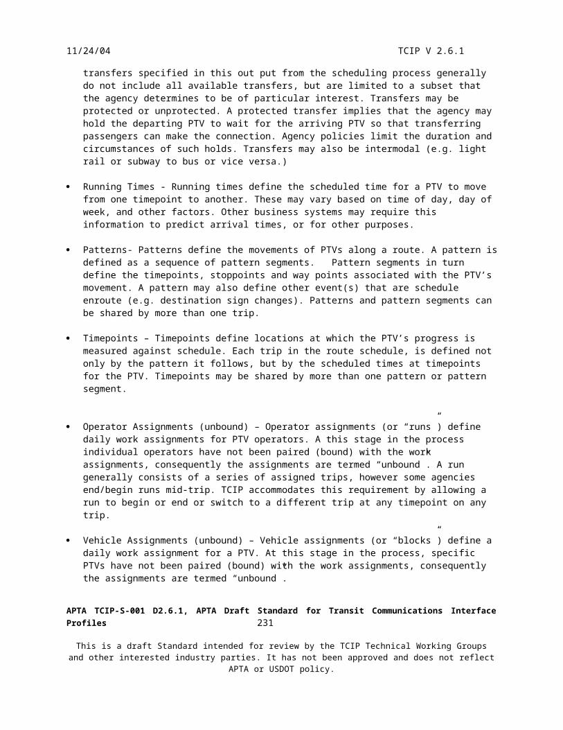
11/24/04 TCIP V 2.6.1
Figure 6.2.3.2: Narrowband TCIP Message Format
6.2.3.2.1 Fixed Length Data Elements
Fixed Length data elements shall be data elements with the following base types and subtypes:
BOOLEAN – one octet fieldBYTE – one octet fieldDATE – four octet fieldDATETIME – six octet fieldDURTIME – four octet fieldIDENL – four octet fieldIDENS – two octet fieldLONG – four octet fieldSCHTIME – four octet fieldSHORT – two octet fieldTIME – four octet fieldUBYTE – one octet fieldULONG – four octet fieldUSHORT – two octet field
The fixed length fields shall be placed in the message most to least significant byte.
APTA TCIP-S-001 D2.6.1, APTA Draft Standard for Transit Communications Interface Profiles 233
This is a draft Standard intended for review by the TCIP Technical Working Groups and other interested industry parties. It has not been approved and does not reflect APTA or USDOT policy.

11/24/04 TCIP V 2.6.1
Type 1 Data Field: Fixed Length Data Element
Data Field Structure
Element Databit 0bit 7 123456
1 bit element: BOOLEAN
00 0 0 0 0 0 B
FALSE: B = 0TRUE: B = 1
bit 0bit 7 123456
MSB
1 octet elements: BYTE, UBYTE
LSB
8-bit data fieldbits 8 - 15MSB
2 octet elements: INTEGER (2 octet), IDENS, SCHTIME, SHORT, USHORT
bits 0 - 7 LSB
MS Byte
LS Byte
4 byte elements: DATE, DATETIME, DURTIME, IDENL, LONG, TIME, ULONG
MS Byte
LS Byte
bits 8 - 15
bits 16 - 23
bits 24 - 31MSB
bits 0 - 7 LSB
bit 0bit 7 123456
bit 0bit 7 123456
6 octet element
bits 8-15
bits 24 - 31
bits 0-7
bits 16-23
bits 8-15
bits 0-7
MSB
LSB
MS Byte
LS Byte
USHORT-Encodedcentury and year
ULONG EncodedMMDDhhmmss
bit 0bit 7 123456
Figure 6.2.3.2.1: Narrowband TCIP Fixed Length Element Type
6.2.3.2.2 Variable Length Data Elements
Variable length data elements shall be data elements with the following base types and sub types:
FOOTNOTE -up to 255 charactersMEMLONG -up to 2,000,000 octetsMEMSHORT23 -up to 23 octetsMEMSHORT -up to 2047 octets
APTA TCIP-S-001 D2.6.1, APTA Draft Standard for Transit Communications Interface Profiles 234
This is a draft Standard intended for review by the TCIP Technical Working Groups and other interested industry parties. It has not been approved and does not reflect APTA or USDOT policy.

11/24/04 TCIP V 2.6.1
MEMVSHORT -up to 255 octetsNAME2 -up to 2 charactersNAME3 -up to 3 charactersNAME4 -up to 4 charactersNAME5 -up to 5 charactersNAME6 -up to 6 charactersNAME7 -up to 7 charactersNAME8 -up to 8 charactersNAME9 -up to 9 charactersNAME10 -up to10 charactersNAME11 -up to 11 charactersNAME12 -up to 12 charactersNAME13 -up to 13 charactersNAME14 -up to 14 charactersNAME15 -up to 15 charactersNAME16 -up to 16 charactersNAME17 -up to 17 charactersNAME18 -up to 18 charactersNAME20 -up to 20 charactersNAME21 -up to 21 charactersNAME22 -up to 22 charactersNAME23 -up to 23 charactersNAME24 -up to 24 charactersNAME25 -up to 25 charactersNAME30 -up to 30 charactersNAME40 -up to 40 charactersNAME60 -up to 60 charactersTELEPHONE -up to 16 characters
A variable length field shall be in the message by an element length subfield, and an element data subfield. The element length subfield shall store the length information in the lower 7 bits of each octet, and shall use the most significant bit (7 bit) as a continuation bit. The element length subfield shall be a maximum of 3 octets long allowing it to support up to 2,097,152 length element data fields.
The element data subfield shall follow the element length subfield and shall contain as many octets as are specified by the element data subfield. For UTF8String types, the characters in the string shall be stowed in the element data subfield in the order normally read. For OCTET STRING types, the octets shall be stored in from first to last, in the message, in the same order as their appearance in the OCTET STRING.
Figure 6.2.3.2.2 depicts the implementation of variable length data elements.
APTA TCIP-S-001 D2.6.1, APTA Draft Standard for Transit Communications Interface Profiles 235
This is a draft Standard intended for review by the TCIP Technical Working Groups and other interested industry parties. It has not been approved and does not reflect APTA or USDOT policy.
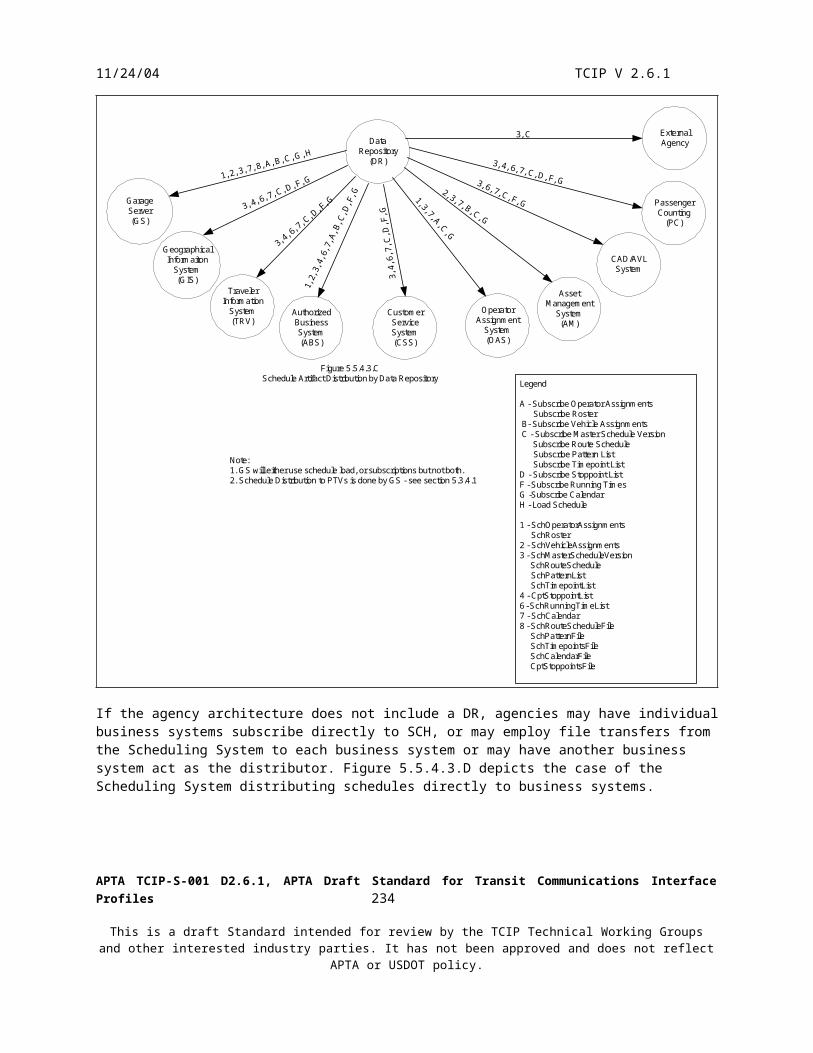
11/24/04 TCIP V 2.6.1
Figure 6.2.3.2.2: Narrowband TCIP Variable Length Data Element Type
6.2.3.2.3 Enumerated Data Elements
Enumerated data fields shall be signified by the use of the ENUMERATED keyword in their ASN.1 definition. Some TCIP enumerated data types define specific numeric index values for each token value listed for the data element. In those cases the index value used to identify the token shall be the number assigned to that token in the data element definition. For any enumerated element without specified index values corresponding to each token,
APTA TCIP-S-001 D2.6.1, APTA Draft Standard for Transit Communications Interface Profiles 236
This is a draft Standard intended for review by the TCIP Technical Working Groups and other interested industry parties. It has not been approved and does not reflect APTA or USDOT policy.

11/24/04 TCIP V 2.6.1
the index value of the first specified token in the data element definition shall be one. Each subsequently defined token value shall have a corresponding index value incremented by one.
For example, if a data element definition specified allowed values of A,B,C,D and E, and no corresponding index values were specified, then the index values would be:
A=1B=2C=3D=4E=5
And values 0, 6-255 would be invalid.
If, on the other hand the data element definition specified that the values were:A=1B=2C=3D=4--5 reservedE=6--7-10 reserved--11-20 local use--21-200 reserved
Then the values 0, 5, 7-10, and 21-255 would be invalid. The values 1-4 and 6 would be used as index values as indicated in the data element definition. The values 11-20 would be valid if locally defined, and would have the locally defined significance. If the values 11-20, or any subset of those values were not locally defined, those undefined values would be invalid.
Figure 6.2.3.2.3 depicts the implementation of Enumerated Data Elements.
APTA TCIP-S-001 D2.6.1, APTA Draft Standard for Transit Communications Interface Profiles 237
This is a draft Standard intended for review by the TCIP Technical Working Groups and other interested industry parties. It has not been approved and does not reflect APTA or USDOT policy.
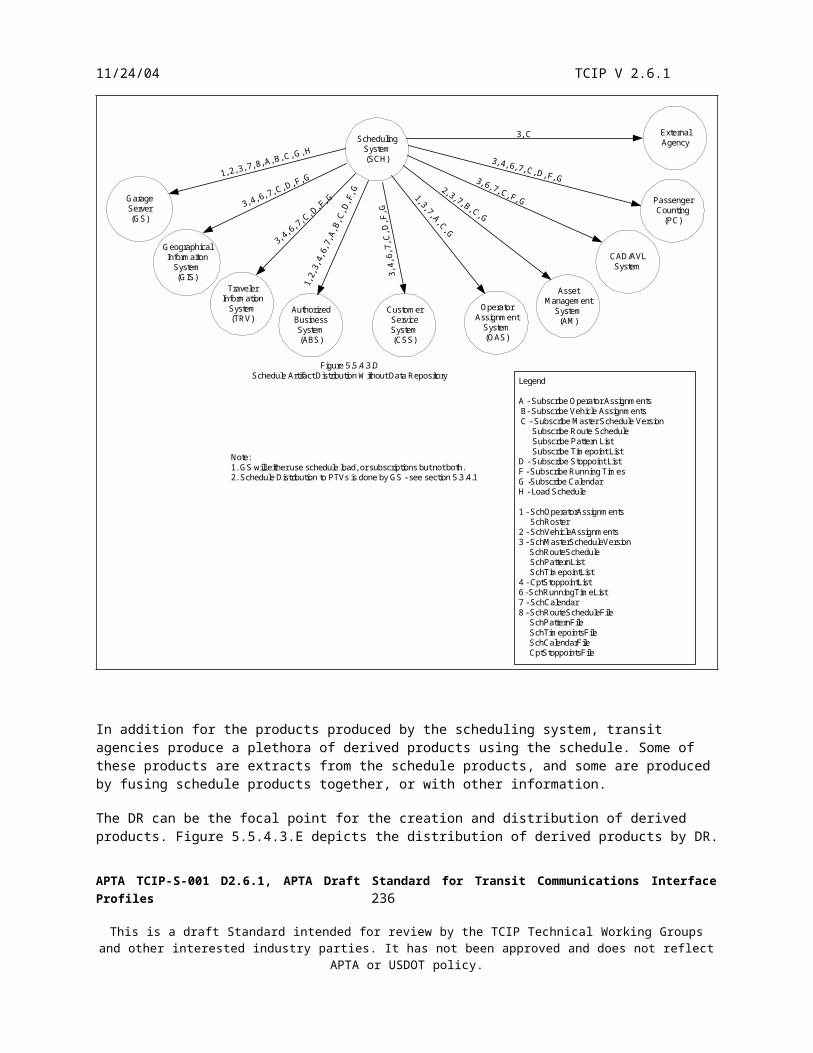
11/24/04 TCIP V 2.6.1
Figure 6.2.3.2.3: Narrowband TCIP ENUMERATED Element Type
6.2.3.2.4 Data Frames
Data frame encoding shall be performed similarly to the message encoding, but without the message identifier. 1-15 octets shall encode the entry-present-map for the frame. CHOICE fields shall be encoded as if the CHOICE were not present. A separate bit shall define the presence or absence of the CHOICE alternative. A bit set to zero shall indicate that the field is not present, and a bit set to one shall indicate that the field is present. If an entry is not specified as OPTIONAL or is a CHOICE alternative in the message definition, then it shall be an error to set the corresponding bit to zero. Bits representing entries beyond the last entry specified in the data frame definition (if any) shall be set to zero.
The same 5 types of data fields allowed in a message body shall be allowed in a data frame body. Figure 6.2.3.2.4 depicts encoding of a TCIP Data Frame.
APTA TCIP-S-001 D2.6.1, APTA Draft Standard for Transit Communications Interface Profiles 238
This is a draft Standard intended for review by the TCIP Technical Working Groups and other interested industry parties. It has not been approved and does not reflect APTA or USDOT policy.
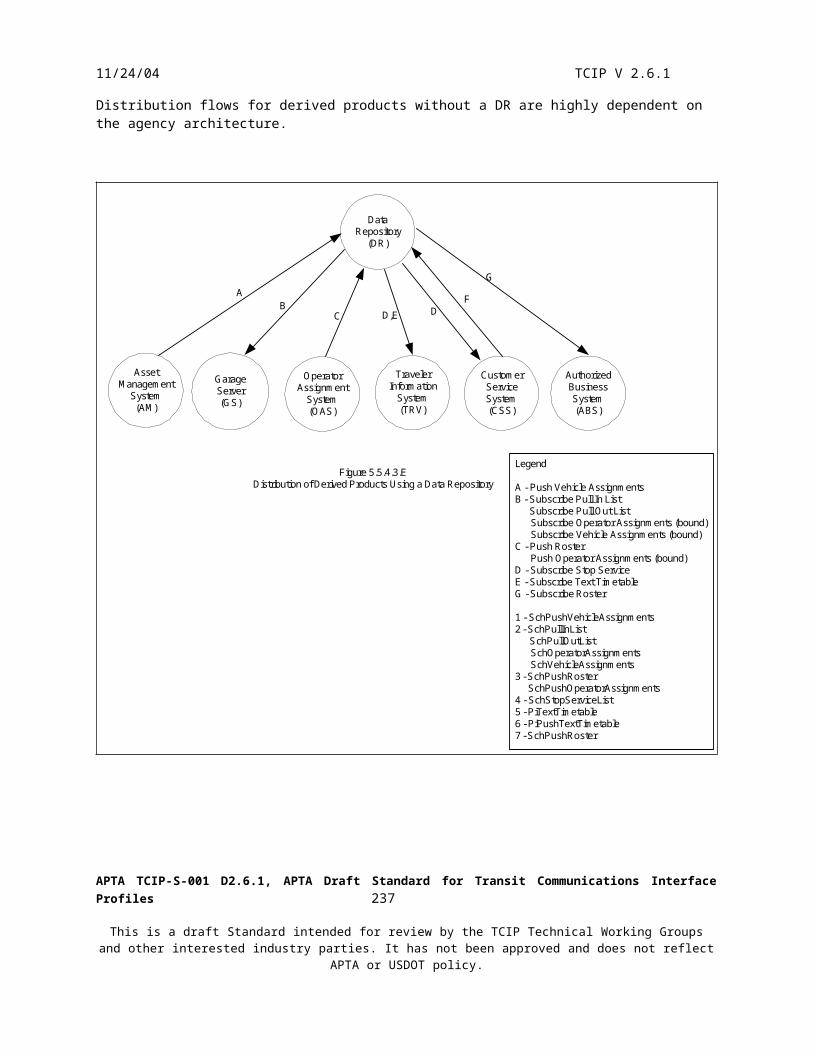
11/24/04 TCIP V 2.6.1
APTA TCIP-S-001 D2.6.1, APTA Draft Standard for Transit Communications Interface Profiles 239
This is a draft Standard intended for review by the TCIP Technical Working Groups and other interested industry parties. It has not been approved and does not reflect APTA or USDOT policy.

11/24/04 TCIP V 2.6.1
Figure 6.2.3.2.4: Narrowband TCIP Data Frame Type
6.2.3.2.5 SEQUENCE OF Constructor
The sequence of constructor shall provide the encoding for a sequence of data frames or data elements inside a message or data frame. The data field shall begin with a 16-bit count field that defines the number of items in the sequence. The sequence of items shall follow the count. All items in the sequence shall be of the same type. Figure 6.2.3.2.5 illustrates the SEQUENCE OF constructor.
Figure 6.2.3.2.5: Narrowband TCIP SEQUENCE OF Type
APTA TCIP-S-001 D2.6.1, APTA Draft Standard for Transit Communications Interface Profiles 240
This is a draft Standard intended for review by the TCIP Technical Working Groups and other interested industry parties. It has not been approved and does not reflect APTA or USDOT policy.

11/24/04 TCIP V 2.6.1
7. TCIP Dialog Patterns
7.1 Subscription Pattern
A subscription dialog is a three (3) message dialog pattern. The pattern defines the conversation between a subscriber and a publisher. The publisher is the owner/producer/provider of information required by the subscriber who requires the information. The three messages are a subscription request, a subscription response, and an error notice. The subscription request message and the subscription response message are unique to the individual dialog, however both contain a CPTSubscriptionHeader data frame. The error message is common to all subscription dialogs and is defined as CptSubErrorNotice. If the publisher sends a CptSubErrorNotice at any time, the dialog shall immediately end with no further data exchanges. Receipt of a CptSubErrorNotice, or a failure to communicate, or to receive an expected response shall be recovered by a vendor specified process within the component (subscriber or publisher).
The subscription request message name has the form AaaXxxSub where: Aaa indicates the standard (e.g. Cpt, Sch) where the message is defined. Xxx indicates the name of the subscription (e.g. RouteList). Sub indicates that the message is a subscription request message.
The subscription response message name has the form AaaXxx where: Aaa indicates the standard (e.g. Cpt, Sch) where the message is defined. Xxx indicates the name of the subscription (e.g. RouteList).
The CPTSubscriptionHeader contains a data element defined as CPT-SubscriptionType which allows a subscription dialog to assume 3 forms: The first form is a basic query. The subscriber requests the information and the publisher provides it on a one-
time basis. The second form is the periodic subscription. The subscriber requests the information and the publisher
provides it initially and on a recurring basis at intervals specified in the subscription request. The third form is the event-driven subscription. The subscriber requests the information and the publisher
provides it initially and provides new versions of the information based on events that change the information.
The CPTSubscriptionType also provides the capability for the subscriber to cancel a periodic or event-driven subscription. In the event that the publisher receives a subscription request message (AaaXxxSub) with a subscription header data frame indicating that the subscription is to be cancelled, the publisher shall cease sending the matching AaaXxx messages for the indicated subscription(s). Note that the cancellation message may request the cancellation of a single dialog only with a matching subscription number, or all dialogs for that subscriber of type AaaXxx.
The CPTSubscriptionHeader provides identifiers for the subscriber and the publisher in the fields subscriberIdentifier and hostIdentifier. These fields are of the type CPT-ApplicationID, which is an agency-assigned unique identifier for computer applications within the agency’s architecture. Agencies will need to coordinate with other agencies with whom they share data to ensure uniqueness of these identifiers (e.g. within a metropolitan area).
The CPT-SubscriptionHeader provides an identifier for each subscription of type CPT-RequestIdentifier. This identifier allows multiple subscriptions between a subscriber-publisher pair to exist simultaneously and operate independently.
APTA TCIP-S-001 D2.6.1, APTA Draft Standard for Transit Communications Interface Profiles 241
This is a draft Standard intended for review by the TCIP Technical Working Groups and other interested industry parties. It has not been approved and does not reflect APTA or USDOT policy.
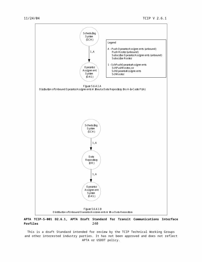
11/24/04 TCIP V 2.6.1
In the event that a periodic, or event driven subscription request arrives at a publisher and the expiration time for the request has already passed, the publisher shall immediately downgrade the request to a basic query, provide a single response to the subscriber (assuming the request is valid) and end the dialog. In the event that the expired request is also invalid for other reasons, the publisher shall respond with a CptSubError notice.
Figures 7.1.A through 7.1.C depict the variations of the subscription pattern.
Subscriber Publisher Subscriber Publisher
AaaXxxSub
AaaXxxCalculation
CompleteComplete
Normal Execution of Query Subscription Dialog
Complete Complete
Calculation
AaaXxxSub
CptSubErrorNotice
Error Response to Query Subscription Dialog
Figure 7.1.AQuery Version of the Subscription Dialog Pattern
APTA TCIP-S-001 D2.6.1, APTA Draft Standard for Transit Communications Interface Profiles 242
This is a draft Standard intended for review by the TCIP Technical Working Groups and other interested industry parties. It has not been approved and does not reflect APTA or USDOT policy.

11/24/04 TCIP V 2.6.1
Subscriber Publisher Subscriber
Subscriber Subscriber
Publisher
Publisher Publisher
AaaXxxSub
AaaXxxCalculation
CompleteComplete
Query Downgrade of Periodic Subscription Dialog
Complete Complete
Calculation
AaaXxxSub
CptSubErrorNotice
Error Response to Periodic Subscription Dialog
AaaXxxSub
AaaXxx
AaaXxx
AaaXxx
Calculation
CompleteComplete SubscriptionExpires
AaaXxx
AaaXxx
AaaXxxSub
Calculation
IntervalCalculation
IntervalCalculation
IntervalCalculation
CancelSubscription
Complete Complete
Normal Execution of Periodic SubscriptionDialog
Subscriber Cancellation of Periodic SubscriptionDialog
Figure 7.1.BPeriodic Version of the Subscription Dialog Pattern
APTA TCIP-S-001 D2.6.1, APTA Draft Standard for Transit Communications Interface Profiles 243
This is a draft Standard intended for review by the TCIP Technical Working Groups and other interested industry parties. It has not been approved and does not reflect APTA or USDOT policy.

11/24/04 TCIP V 2.6.1
Subscriber Publisher Subscriber
Subscriber Subscriber
Publisher
Publisher Publisher
AaaXxxSub
AaaXxxCalculation
CompleteComplete
Query Downgrade of Event-Driven SubscriptionDialog
Complete Complete
Calculation
AaaXxxSub
CptSubErrorNotice
Error Response to Event-Driven SubscriptionDialog
AaaXxxSub
AaaXxx
AaaXxx
AaaXxx
Calculation
CompleteComplete SubscriptionExpires
AaaXxx
AaaXxx
AaaXxxSub
Calculation
EventCalculation
Event
EventCalculation
CancelSubscription
Complete Complete
Normal Execution of Event-DrivenSubscription Dialog
Subscriber Cancellation of Event-DrivenSubscription Dialog
Figure 7.1.CEvent Driven Version of the Subscription Dialog Pattern
Although the subscriber requests the form of the subscription in CPTSubscriptionHeader, the publisher may change (downgrade) the request in the response. The allowed changes by the publisher are: Periodic request changed to Query response. Event-Driven Request changed to Query Response. Periodic Request changed to a longer reporting interval. For example if a subscriber requested information
updates every second to the bus stop inventory the provider might change it to daily or weekly. Subscription expiration date/time changed to an earlier date/time. For example if the subscriber requested a
100 year subscription, the provider might limit the subscription to six months.
The publisher shall notify the subscriber of the downgrade by updating the fields from the subscription requests that are replicated in the response message.
In addition to the request information provided in CPTSubscriptionHeader, the subscription request generally contains additional specifications on the data to be provided that is dialog-specific. There may be dialog-specific limitations on the data in the response. For example if the planned schedule is requested for the next year, but has
APTA TCIP-S-001 D2.6.1, APTA Draft Standard for Transit Communications Interface Profiles 244
This is a draft Standard intended for review by the TCIP Technical Working Groups and other interested industry parties. It has not been approved and does not reflect APTA or USDOT policy.

11/24/04 TCIP V 2.6.1
only been defined for the next six months, the publisher might have a dialog specific option to reduce the scope to the data that actually exists.
A procuring agency may limit the allowable downgrades for any specific subscription dialog. For example, if an agency is procuring a passenger information system that subscribes to bus locations on a periodic basis from a CAD/AVL System, the agency may require the CAD/AVL system provider to service the periodic subscription, and not downgrade it to a query.
Some subscription dialogs are used to exchange large data sets usually expressed as lists that may have small, but frequent changes. Such dialogs may implement query or event-based “row versioning”. In query-based row versioning, the subscriber shall send a query with a field indicating that only data that has changes since a specified date & time should be included in the response from the publisher. In event-based row versioning, the initial query shall cause the publisher to send the entire dataset, however updates to the dataset shall trigger the publisher to send event messages to the subscriber indicating that the message contains only updates since a specified date & time. In either case the message to the subscriber may contain a list of deleted items as well as a list of new or updated items in the list.
In some cases a single subscription dialog is reused a number of times within an agency architecture. An example is when more than one application makes updates to the same information. In such cases, event-based subscriptions typically are used to exchange updates among business systems. Figure 7.1.D depicts and exchange network. In this example dialog X is used to transfer a version of some information to business systems B, C and D from the originator – business system A. Event-driven subscriptions allow B,C and D to exchange row updates to the data. Note that B, C and D must only generate and event and send an update when they generate the change. “Relaying” changes will result in a potential for an undesired event explosion.
CBD
ALegend:
Is interpreted as dialog Y is used with M as thepublisher and N as the subscriber.
M NY
Figure 7.1.DUsing Event-Driven Subscription Dialogs to Distribute Updates to Agency Data
X
X
X
X
X
X
X
X
X
APTA TCIP-S-001 D2.6.1, APTA Draft Standard for Transit Communications Interface Profiles 245
This is a draft Standard intended for review by the TCIP Technical Working Groups and other interested industry parties. It has not been approved and does not reflect APTA or USDOT policy.

11/24/04 TCIP V 2.6.1
Subscription Dialog Definitions
Subscription dialogs derived from the Subscription Dialog Pattern shall each specify:
1. Dialog Name – A unique name for the dialog beginning with the word “Subscribe”
2. TCIP Business Area
3. Dialog Purpose – Defines the purpose of the subscription dialog. Generally this is to convey a particular type of information from a publisher to a subscriber.
4. Subscription Types – Subscriptions may be query, event driven or periodic. Some subscription dialogs support more than one subscription type.
5. Row Updates Supported – If row updates are supported specifies the type(s) of rows (data frames) in the response message that are supported.
6. Subscription Request and Response Messages
7. Dialog Specific Assumptions and Notes
8. Associated file Transfer – Indicates that there is a file transfer that may be used in lieu of the subscription by specifying the name of the response message or “none” indicating that there is no associated file transfer.
9. Events – If the subscription dialog supports event- driven, defines the type(s) of events that trigger updates.
APTA TCIP-S-001 D2.6.1, APTA Draft Standard for Transit Communications Interface Profiles 246
This is a draft Standard intended for review by the TCIP Technical Working Groups and other interested industry parties. It has not been approved and does not reflect APTA or USDOT policy.

11/24/04 TCIP V 2.6.1
7.2 Command-Response Pattern
A Command Response dialog is a two (2) message pattern. The pattern defines the conversation between a controlling entity (controller) and a controlled entity (device). The device performs actions or provides services in response to commands from the controller. The two messages are a command message and a response message.
The controller shall initiate all command response dialogs by sending a command message. The usual case is that the device attempts to perform the command and replies with a response message indicating whether or not the command was executed successfully. A command identifier number of type CPT-CommandID assigned by the controller and conveyed to the device in the command message shall be returned to the controller in the response message from the device allowing the controller to match the response with the previously issued command.
Some dialogs specify the use of the Command Response dialog pattern with one of two variations
In the first variation the dialog specifies that the device only sends a response if a designated field in the command message asks for a specific response. Fields of the type are generally of type CPT-Boolean and have names like verifyCommand, or responseRequired.
In the second variation, the dialog specifies that the device never sends a response, in this case a corresponding response message will not be specified for that dialog.
Some dialogs may specify that the command must be executed within a specified time frame or abandoned. The time frames may be specified in the dialog definition or in the command message. Such dialogs shall specify a response message containing a data element of type CPT-ErrorCode which can be used to indicate that the command was not executed due to a timeout.
Figure 7.2 depicts the execution of the Command Response dialog pattern.
APTA TCIP-S-001 D2.6.1, APTA Draft Standard for Transit Communications Interface Profiles 247
This is a draft Standard intended for review by the TCIP Technical Working Groups and other interested industry parties. It has not been approved and does not reflect APTA or USDOT policy.
11/24/04 TCIP V 2.6.1
Controller Device Controller
Controller Controller
Device
Device Device
Command
ResponseCommandExecuted:ResponseRequired
Normal Execution of Command Response Patternwith a Required Response
Failed Execution of Command Response Patternwith a Required Response
CommandExecutedor Invalid
orTimeout:Response
notRequired
Timeout Failure of Command ResponsePattern with a Required Response
Command Response Pattern without a RequiredResponse
Figure 7.2Command Response Dialog Pattern
Command
ResponseCommand
Invalid:ResponseRequired
Command
ResponseTimeout
Commandnot
Executed:ResponseRequired
Command
Command Response Dialog Definitions
Command-response dialogs derived from the Command-Response Dialog Pattern shall each specify:
1. Dialog Name - A unique name for the dialog beginning with the word “Command”
2. TCIP Business Area
3. Dialog Purpose – Defines the purpose of the command response dialog
4. Response Type – One of “No Response Required”, “Command Elicited” (indicates a response is required only if requested in the command message), or “Response Required”
5. Command and Response Messages
6. Dialog Specific Assumptions and Notes
APTA TCIP-S-001 D2.6.1, APTA Draft Standard for Transit Communications Interface Profiles 248
This is a draft Standard intended for review by the TCIP Technical Working Groups and other interested industry parties. It has not been approved and does not reflect APTA or USDOT policy.

11/24/04 TCIP V 2.6.1
7.3 Report Pattern
A Report Dialog is a two (2) message pattern. The pattern defines the conversation between a reporter entity, (such as a field, or mobile based employee computer), and a receiving entity such as a supervisor hand held device, dispatch system, or Maintenance Management System.
The reporter entity shall generate the report based on actual conditions, or human input, not based on a query or subscription request from the receiving entity. Because reports are generated on an ad-hoc basis and from a variety of sources, the reports shall be given unique identifiers by combining their source identifier with the date-time of the report.
The report pattern is not intended to broadcast notifications to a wide distribution list, and the receiver shall acknowledge receipt of the report. Vendor/Agency defined recovery procedures shall be executed by the reporter if the acknowledgement is not received by the reporter. Such procedures may include retrying the transmission, generating an alarm, notifying the operator (if applicable), or aborting the dialog.
Figure 7.3 depicts the execution of the Report dialog pattern.
Reporter Receiver Reporter Receiver
Report Message
Acknowledgement
Report Message
VendorDefinedTimeout
VendorDefined
RecoveryProcedure
Normal Execution of the Report Pattern Failed Execution of the Report Pattern
Figure 7.3Report Dialog Pattern
Report Dialog Definitions
Report dialogs derived from the Report Dialog Pattern shall each specify:
1. Dialog Name – A unique name for the dialog beginning with the word “Report”
2. TCIP Business Area
3. Dialog Purpose – Defines the purpose of the report dialog
4. Report and Acknowledgement Messages
5. Dialog Specific Assumptions and Notes
APTA TCIP-S-001 D2.6.1, APTA Draft Standard for Transit Communications Interface Profiles 249
This is a draft Standard intended for review by the TCIP Technical Working Groups and other interested industry parties. It has not been approved and does not reflect APTA or USDOT policy.

11/24/04 TCIP V 2.6.1
7.4 Silent Alarm Pattern
The Silent Alarm pattern is a unique pattern specifically intended for use with transit vehicles with a silent alarm feature. The dialog shall be initiated by the vehicle computer when the alarm is triggered, and the vehicle computer shall send a ImSilentAlarm message to the dispatch computer system. The vehicle computer may perform other agency/vendor defined actions as a result of the trigger.
After an agency/vendor defined notification and acknowledgment between the dispatch computer and the dispatcher, the dispatch computer shall provide an acknowledgment (ImSilentAlarmAck) to the vehicle. The dispatcher and/or the dispatch computer may initiate other vendor/agency defined actions as a result of the notifications. For example, this may include changing the location reporting update rate for the vehicle. Upon receipt of the acknowledgement, the vehicle computer shall use a vendor/agency defined covert signal to notify the driver that the acknowledgement has been received.
Optionally, the operator may use the Mobile Data Terminal to cause an ImAlarmCancel message to the dispatch computer to notify the dispatcher of a request to terminate the alarm condition, however this message shall not itself cause the alarm condition to be reset or closed, nor shall it end the SlientAlarm Dialog.
The dialog shall end when the dispatcher determines that the alarm was false or that the incident requiring the alarm has concluded, and enters this into the dispatch computer. The dispatch computer shall send a closing message (ImSilentAlarmClose) to the vehicle computer. The dispatch computer may reset other agency/vendor defined states related to the alarm based on the dispatcher’s decision to close the alarm.
The vehicle computer upon receipt of the closing message, shall reset any vendor/agency defined states (e.g. Mobile Data Terminal icon changes) and shall close out the alarm.
Figure 7.4 depicts the execution of the Silent Alarm dialog pattern.
APTA TCIP-S-001 D2.6.1, APTA Draft Standard for Transit Communications Interface Profiles 250
This is a draft Standard intended for review by the TCIP Technical Working Groups and other interested industry parties. It has not been approved and does not reflect APTA or USDOT policy.

11/24/04 TCIP V 2.6.1
Dispatch Computer(CAD) DispatcherOperator
Vehicle Computer(PTVSEC, PTVOPR)
Trigger Alarm*
ImSilentAlarm
Notify*
AgencyDefinedActions
Acknowledgement*
ImSilentAlarmAck
Covert Signal*
Cancel Alarm*ImAlarmCancel
Notify*
Close*
ImSilentAlarmClose
Clear Alarm*
*Agency/Vendor defined transactions
Figure 7.4Normal Execution of the Silent Alarm Dialog
AgencyDefinedActions
AgencyDefinedActions
AgencyDefinedActions
AgencyDefinedActionsAgency
DefinedActions
Silent Alarm Dialog Definition
Because the Silent Alarm Pattern is only used to define the Silent Alarm dialog, there are no requirements for the derivation of new dialogs from this pattern.
APTA TCIP-S-001 D2.6.1, APTA Draft Standard for Transit Communications Interface Profiles 251
This is a draft Standard intended for review by the TCIP Technical Working Groups and other interested industry parties. It has not been approved and does not reflect APTA or USDOT policy.

11/24/04 TCIP V 2.6.1
7.5 Load Pattern
This pattern is intended to load large files from a fixed business system source to a corresponding onboard component, field component, or a business system acting as a proxy for one or more field or onboard components (destination). As an example a Garage Server may serve as a proxy for the Vehicle Logic Units (VLUs) on a group of PTVs. Other business systems can load files onto the proxy using this dialog and the proxy can then use the same dialog to load the files onto the appropriate VLUs when they are available (in WLAN coverage). Thus a proxy would act as a destination in one instance of the dialog and as a source in another instance of the same dialog.
Files may include configuration information, software applications or other information. Loads may be performed using a laptop computer, or a wireless LAN or other network connection. Loads may also be performed using portable media such as flash cards or CDs (batch mode). This dialog pattern is applicable to loads performed over a network connection or a laptop plugged into the onboard/field component. Normally loads will not be performed over narrowband radio networks.
The source component (laptop or source business system) shall be responsible for maintaining configuration control over the files to be loaded. The source component shall be responsible for keeping track of the correct version number(s) and/or effective dates of the loaded file(s) as appropriate for the destination component. The correct current version number and/or effective dates for an onboard component may be the same for all vehicles in the fleet or different by class of vehicle, garage-base, or by individual vehicle. Similarly, the correct version number and/or effective date for a field component may be the same for all stoppoints, field locations etc., or may be tailored on a site by site or component by component basis.
The applicability field in the load file’s header shall indicate the specific PTVs, stoppoints etc. to which a file applies. This field is not necessary when loading a file or files to a specific onboard or field component, but is required when loading a proxy component. The proxy shall use the applicability field to determine what files to load to what PTVs, stoppoints etc.
The destination component shall be responsible for keeping track of the version number(s) and/or effective dates of the load files it has stored. Destination components may or may not keep multiple versions of the same load file depending on internal memory size and file management capabilities. In addition to the version number and/or effective date, some files are row-updatable. The destination shall keep track of the most recent update date-time on hand. The source shall keep track of all updates and when they are applied. Upon receipt of a request for updates, the source shall transfer only the changes to a version of a file that is already on hand at the destination.
Destination components shall ensure that if a file is incompletely loaded (e.g. due to network failures or loss of wireless LAN availability) that the destination component remains usable.
The load initiation shall always performed by the destination end by sending a CptOnboardVersionNotice message to the source component, however the source component can trigger the destination component to initiate the load by sending a CptForceLoad message. Note that an load initiation may not result in an actual file transfer, as the initial exchange of messages (CptOnboardVersionNotice, and CptVersionInfo between the destination and source components may result in a determination that the correct up-to date file versions are already on hand in the destination component.
The destination component shall initiate a load upon: Receipt of a CptForceLoad message from the source component. Receipt of a notification (via the “Subscribe Wireless LAN Status” Dialog) that the wireless LAN has
become available and the minimum load request interval (see below) has elapsed since the last load initiation. Normally this trigger applies to mobile (e.g. PTV-based) destination components.
APTA TCIP-S-001 D2.6.1, APTA Draft Standard for Transit Communications Interface Profiles 252
This is a draft Standard intended for review by the TCIP Technical Working Groups and other interested industry parties. It has not been approved and does not reflect APTA or USDOT policy.

11/24/04 TCIP V 2.6.1
Determination that the maximum load request interval (see below) has expired and the wireless LAN or another high-capacity communications path is available.
The minimum load request interval is a parameter that prevents the onboard destination components from continuously initiating loads when in marginal wireless LAN coverage. In this situation it is possible for the “Subscribe Wireless LAN” Dialog to frequently indicate failures and recoveries of the wireless LAN. Instead of having the onboard component interpret each recovery as a new visit to the garage, this parameter governs how long the onboard component must wait before initiating a new load request. This interval shall be overridden by receipt of a CptForceLoad message. The value of this parameter is locally defined. A recommended initial default interval is 60 minutes.
The maximum load request interval is a parameter that prevents the destination components from failing to initiate new loads due to a prolonged continuous period of wireless LAN or other communications path availability. If the communications path is always available, the “Subscribe Wireless LAN” Dialog will not send event-driven notifications of wireless LAN availability resulting in the destination components failing to obtain new loads. If the component’s communications path remains available coverage for a period exceeding this interval, the destination component shall initiate a new load. The value of the maximum load request interval is locally defined. A recommended initial default interval is 240 minutes (4 hours).
The dialog pattern executes as follows:
1. The onboard or field component shall initiate the dialog based on one of the three criteria described above and send a CptOnboardVersion Notice message to the source component. This message informs the source component of the current version(s) effective dates and/or update times of the load files stored in the destination component.
2. The source component upon receipt of the CptOnboardVersionNotice shall send a CptCurrentVersionNotice to the destination component. This message informs the destination component of the file version(s) that should be stored by the destination component, and optionally provides a list of files to delete.
3. The destination component shall determine:A. The files that need to be loadedB. Whether there will be room to store the files to be loaded (allowing for space freed up by file deletions)C. Whether the files specified in the CptCurrentVersionNotice message are files that the destination component should have (e.g. farebox doesn’t use VLU software files).
4. The destination component shall send a CptLoadControl message to the source component ending the load dialog or requesting the first file to be loaded. The dialog can be ended at this point due to:
A. Invalid information in the CptCurrentVersionNotice messageB. Insufficient storage in the destination componentC. All files are current
5. If a valid file load was requested, the source component shall send the requested file or file update. If the file request is invalid, the source component shall send a CptBadLoadRequest message and the dialog shall end.
6. Upon receipt of the file or file update the destination component shall validate the file (manufacturer defined but including a verification of file length at a minimum), and shall determine whether additional files are needed. The destination component shall send a CptLoadControl message to the source component ending the dialog or requesting the next file. If a file is requested, go to step 5 above.
Figure 7.5 A-B depicts the execution of the Load dialog pattern.
APTA TCIP-S-001 D2.6.1, APTA Draft Standard for Transit Communications Interface Profiles 253
This is a draft Standard intended for review by the TCIP Technical Working Groups and other interested industry parties. It has not been approved and does not reflect APTA or USDOT policy.

11/24/04 TCIP V 2.6.1
Initiation Triggers for Load Dialogs
Load DialogSubscribe Wireless LAN
Status DialogSource
Component Destination ComponentOnboard WLAN
Component
CptForceLoad ObWLANStatus
MaximumLoad
IntervalExpires
- or -
Load Dialog with All Files Current
SourceComponent
CalculateCurrentFile List
InitiateDialog
CptOnboardVersionNotice
CptCurrentVersionNotice
CptLoadControl
SourceComponent
Load Dialog with Insufficient Memory
CalculateCurrentFile List
InitiateDialog
DetermineInsufficient
Memoryand StopDialog
Figure 7.5.AThe Execution of the Load Dialog Pattern
CptOnboardVersionNotice
CptCurrentVersionNotice
CptLoadControl
DestinationComponent
Destination Component
APTA TCIP-S-001 D2.6.1, APTA Draft Standard for Transit Communications Interface Profiles 254
This is a draft Standard intended for review by the TCIP Technical Working Groups and other interested industry parties. It has not been approved and does not reflect APTA or USDOT policy.

11/24/04 TCIP V 2.6.1
Normal Execution of Load Dialog
SourceComponent
DestinationComponent
CalculateCurrent File List
Inititate Dialog
Validate Load/Delete Files
Request/FirstFile
ValidateFile
RequestNext File
Validate File/Load
Complete
ValidateFile
RequestNext File
CptOnboardVersionNotice
CptCurrentVersionNotice
CptLoadControl
File 1
File 2
File N
CptLoadControl
CptLoadControl
CptLoadControl
CptLoadControl
Load Dialog with Bad File
Source Component Destination Component
CalculateCurrentFile List
InititateDialog
ValidateLoad/Delete
FilesRequest/First File
ValidateFile/LoadComplete
CptOnboardVersionNotice
CptCurrentVersionNotice
CptLoadControl
File 1
CptLoadControl
Load Dialog with Bad File Request
Source Component Destination Component
CptOnboardVersionNotice
CptCurrentVersionNotice
CptLoadControl
CptBadLoadRequest
Figure 7.5.B Execution of the Load Dialog Pattern
APTA TCIP-S-001 D2.6.1, APTA Draft Standard for Transit Communications Interface Profiles 255
This is a draft Standard intended for review by the TCIP Technical Working Groups and other interested industry parties. It has not been approved and does not reflect APTA or USDOT policy.
11/24/04 TCIP V 2.6.1
Load Dialog Definitions
Load dialogs derived from the Load Dialog Pattern shall each specify:
1. Dialog Name – A unique name for the dialog beginning with the word “Load”
2. TCIP Business Area
3. Dialog Purpose – defines the purpose of the load dialog. Generally this is to transfer a file or list of files from a source to a destination – if required.
4. Row Updates Supported – Fore each file (message) that supports row updates, specify the message and the type(s) of rows (data frames) in the file that are supported.
5. Load File Messages
6. Dialog Specific Assumptions and Notes
7. Associated File Transfers – Indicates what loaded files may be moved using a file transfer in lieu of the load dialog. Note that this substitution may be appropriate between business systems, but usually not between a business system and an onboard or field entity. This section will indicate “None” if there are no associated file transfers.
APTA TCIP-S-001 D2.6.1, APTA Draft Standard for Transit Communications Interface Profiles 256
This is a draft Standard intended for review by the TCIP Technical Working Groups and other interested industry parties. It has not been approved and does not reflect APTA or USDOT policy.

11/24/04 TCIP V 2.6.1
7.6 Unload Pattern
This pattern is intended to unload large files to a destination (usually fixed) business system from a corresponding source (usually onboard or field) component. If files are unloaded to a proxy server (e.g. Garage Server), the unload dialog(s) may also be used to transfer the unloaded files to another business system (e.g. Data Repository). Files may include configuration information, fare collection data, schedule adherence and other operator performance data or other information. Unloads may be performed using a laptop computer, or a wireless LAN or other network connection. Unloads may also be performed using portable media such as flash cards or CDs (batch mode). This dialog pattern is applicable to unloads performed over a network connection or a laptop plugged into the source component. Normally unloads will not be performed over narrowband radio networks.
The destination component (laptop or fixed business system) shall be responsible for maintaining configuration control over the unloaded files. The source component shall be responsible for storing the files to be unloaded until the file is listed for deletion in a CptUnloadControl message or until the source component is forced to delete the file due to lack of storage capacity. The algorithm for determining when a file is to be deleted due to lack of storage capacity shall be manufacturer defined.
The unload initiation shall be always performed by the source component by sending a CptFilesToUnload message to the destination component. Note that a unload initiation may not result in an actual file transfer.
The source component shall initiate a unload based upon: Receipt of a notification (via the “Subscribe Wireless LAN Status” Dialog) that the wireless LAN has
become available and there are stored files waiting to be unloaded. This trigger usually applies only to mobile (PTV-based) sources.
Determination the wireless LAN or other high-capacity communications link is available, and a new file has become ready to unload.
Receipt of a CptForceUnload message from the destination component. This message exists primarily to trigger the unload to a laptop plugged into the source. It can also be used to elicit an unload from one business system (proxy) to a destination business system.
The dialog pattern executes as follows:
1. The source component shall initiate the dialog based on one of the 3 criteria described above and shall send a CptFilesToUnload message to the destination component. This message informs the destination component of the begin and end times for the data contained in the file, file type(s), version number(s) and/or effective dates of the files stored in the source component awaiting a unload.
2. The destination component upon receipt of the CptFilesToUnload message shall send a CptUnloadControl message to the source component. This message informs the source component of the next file to unload (if applicable) and any files to be deleted.
3. The source component shall determine:
A. If an available file was requested in the CptUnloadControl message
B. Whether any files are to be deleted without unloading them. For example the destination component may have successfully received an unload on a previous attempt, but been unable to notify the source component due to a loss of WLAN coverage.
4. The source component shall delete any files specified to be deleted, and if an unload was requested (that is available), shall initiate sending the file. If no files are requested, the dialog ends.
5. If a file is specified for deletion by the destination component, and is not on hand in the source component, the deletion request shall be ignored by the source component.
APTA TCIP-S-001 D2.6.1, APTA Draft Standard for Transit Communications Interface Profiles 257
This is a draft Standard intended for review by the TCIP Technical Working Groups and other interested industry parties. It has not been approved and does not reflect APTA or USDOT policy.

11/24/04 TCIP V 2.6.1
6. If a file is specified for unloading by the destination component and the file is not on hand, the source component shall send a CptUnloadRequestError message to the destination component and shall terminate the dialog. The source component may re-initiate the dialog immediately if the WLAN is still available and there are still files to unload.
7. Upon receipt of an unloaded file, the destination component shall send a CptUnloadControl message to the source component, and the dialog goes to step 3 above. The destination end shall be responsible for including the successfully unloaded file in the files to delete section of the CptUnloadControl message.
Figure 7.6 depicts the execution of the unload dialog pattern.
Normal Execution of Unload Dialog
DestinationComponent Source Component
Calculate FileStatus
Inititate Dialog
ValidateRequest
CptUnloadcontrol
File 1
File 2
File N
DestinationComponent Source Component
ValidateRequest
ValidateRequest
CompleteUnload
CptUnloadcontrol
CptFilesToUnload
CptUnloadcontrol
CptUnloadcontrol
File 3
CptUnloadcontrol
CptFilesToUnload
CptUnloadRequestError
Unload Dialog with Bad File Specified
Figure 7.6 Unload Dialog Pattern
Unload Dialog Definitions
Unload dialogs derived from the Subscription Dialog Pattern shall each specify:
1. Dialog Name – A unique name for the dialog beginning with the word “Unload”
2. TCIP Business Area
APTA TCIP-S-001 D2.6.1, APTA Draft Standard for Transit Communications Interface Profiles 258
This is a draft Standard intended for review by the TCIP Technical Working Groups and other interested industry parties. It has not been approved and does not reflect APTA or USDOT policy.

11/24/04 TCIP V 2.6.1
3. Dialog Purpose – Define the purpose of the unload dialog. Generally this is to convey a particular type of historical information from a source to a destination.
4. Unload Files Messages – the names of the unload file message(s) transferred by the dialog.
5. Dialog Specific Assumptions and Notes
6. Associated File Transfer(s) – Lists the file transfers that (by message name of unloaded file) that may be used in lieu of this dialog. Usually this substitution is applicable between business systems and not when transferring files from onboard or field components.
7.7 Voice Radio Call Patterns
Two patterns define voice radio calls between mobiles, and central. The Operator Initiated Voice Radio Call Pattern, and the Dispatcher-Initiated Voice Radio Call Pattern. These patterns define the interactions between the VLU/MDT and the CAD/AVL System, and the annunciation system, but do not specify the radio control protocol, or the appearance or content of display screens or other operator interfaces.
These dialogs are intended to operate with a variety of one and two bus radio solutions, and thus do not assume that data messaging between the CAD/AVL System and the VLU/MDT is available while voice calls are in effect.
Voice Radio Call Dialog Definitions
The patterns defined in this section are used in unique dialogs. As other dialogs are not derived from these patterns, there are no requirements for defining such derivative dialogs.
7.7.1 Operator Initiated Voice Radio Call Pattern
This pattern defines the sequence of events in a dialog where the vehicle operator requests a voice conversation with the dispatcher. This includes the case where the operator activated a covert microphone. The operator requests the voice call via vendor-specific mechanism such as a MDT transaction, punching a button etc. If the VLU and MDT are separate components connected by a messaging interface, and the request is made via the MDT; the MDT shall send the ObVoiceRequest message to notify the VLU of the request. Other onboard architectures may not need this message.
The VLU/MDT shall send a CcOperatorCallRequest message to the CAD/AVL System. The CAD/AVL System shall notify the dispatcher of the request using vendor defined mechanisms. The dispatcher decides to accept or deny the call, and notifies the CAD/AVL of the result using vendor-defined mechanisms.
If the dispatcher denies the call, the CAD/AVL System shall send a CcDenyCallRequest message to the VLU/MDT. The VLU/MDT shall inform the operator that the call request was denied and the dialog shall end. If the VLU and MDT are separate components connected by a messaging interface; the VLU shall send the ObVoiceRequestProgress message to notify the MDT of the denial.
If the dispatcher accepts the call, then the CAD/AVL System shall notify the radio system of the call to be set up using vendor-specific mechanisms. The radio system may provide a channel number to be conveyed to the vehicle for the voice call. The CAD/AVL System shall send a CcAcceptCallRequest message to the VLU/MDT. The VLU/MDT shall provide an indication that the call was accepted to the operator. If the VLU and MDT are separate components connected by a messaging interface; the VLU shall send the ObVoiceRequestProgress message to notify the MDT of the acceptance. The VLU/MDT shall use a vendor-specific means to indicate the call setup to the voice radio. If the call requires the annunciation system (e.g. covert microphone call) the VLU
APTA TCIP-S-001 D2.6.1, APTA Draft Standard for Transit Communications Interface Profiles 259
This is a draft Standard intended for review by the TCIP Technical Working Groups and other interested industry parties. It has not been approved and does not reflect APTA or USDOT policy.
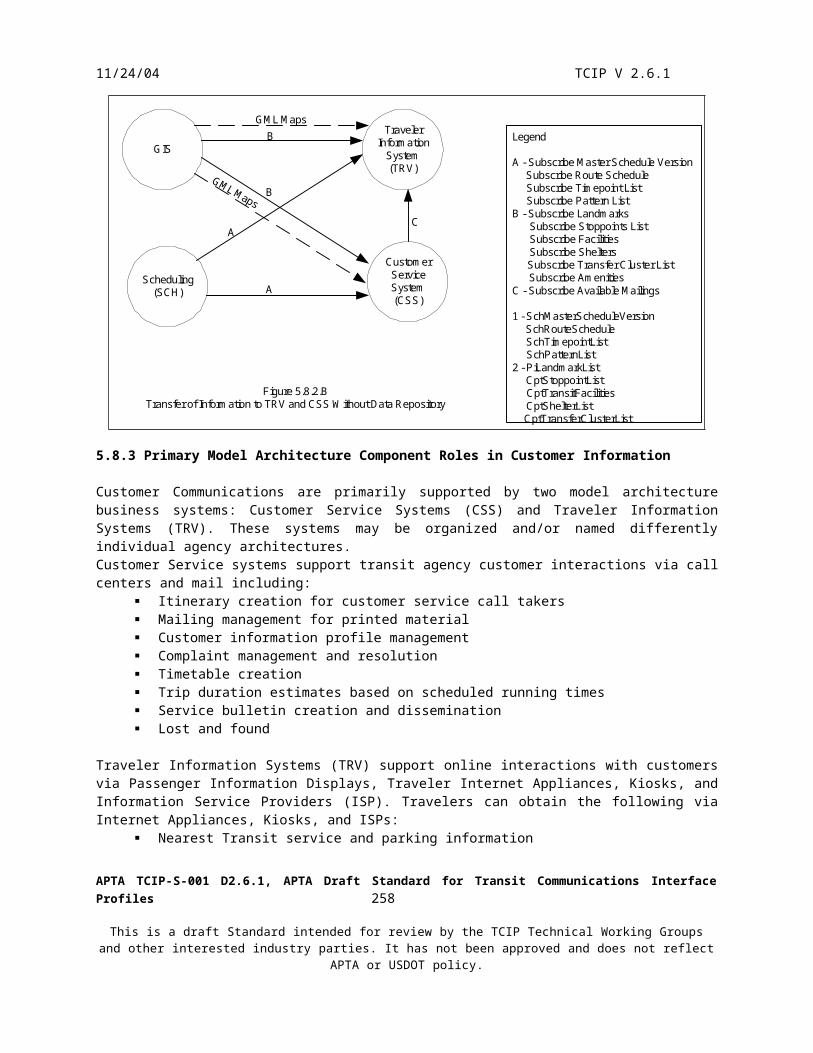
11/24/04 TCIP V 2.6.1
shall send a CcAnnunciationCallSetup message to the annunciation system. At this point the voice call is established.
The operator-initiated voice call is terminated by the dispatcher who provides a vendor-specific indication to the CAD/AVL System that the call should be terminated. The CAD/AVL System shall use a vendor-specific mechanism to notify the radio system that the call should be terminated. The radio system terminates the voice radio connection, and shall provide a vendor-specific indication to the VLU/MDT that the call has ended.
The VLU/MDT shall notify the operator that the call has ended. If the VLU and MDT are separate components connected by a messaging interface; the VLU shall send the ObVoiceRequestProgress message to notify the MDT of the call termination. If the annunciation system was included in the call, the VLU shall send a CcCallTermination message to the annunciator.
Figure 7.7.1 A-B depicts the operator initiated voice radio call.
APTA TCIP-S-001 D2.6.1, APTA Draft Standard for Transit Communications Interface Profiles 260
This is a draft Standard intended for review by the TCIP Technical Working Groups and other interested industry parties. It has not been approved and does not reflect APTA or USDOT policy.

11/24/04 TCIP V 2.6.1
CAD/AVL VLU/MDT
CcOperatorCallRequest
CcAcceptCallRequest
Voice Call In Effect
(Vendor-Specific) Display voicecall request to dispatcher
(Vendor-Specific) Dispatchercall accept
(Vendor-Specific) Radio controlinitiate call
(Vendor-Specific) Dispatcherends call
(Vendor-Specific) Radiocontrol end call
(Vendor-Specific)Operator voice call request
(Vendor-Specific) Indication ofactive call to operator
(Vendor-Specific) Radiocontrol to set up call
CcAnnunciationCallSetup toannunciation system
(Vendor-Specific) Call endindication from radio
(Vendor-Specific) Call endindication to operator
CcCallTermination toannunciation system
Figure 7.7.1.AA Operator-Initiated Voice Radio Call Pattern (Accepted)
APTA TCIP-S-001 D2.6.1, APTA Draft Standard for Transit Communications Interface Profiles 261
This is a draft Standard intended for review by the TCIP Technical Working Groups and other interested industry parties. It has not been approved and does not reflect APTA or USDOT policy.

11/24/04 TCIP V 2.6.1
CAD PTVCOM
CcOperatorCallRequest
CcDenyCallRequest
(Vendor-Specific) Operatorvoice call request
(Vendor-Specific) Displayvoice call request for dispatcher
(Vendor-Specific)Dispatcher call denial
(Vendor-Specific) Voicecall denial to operator
Figure 7.7.1 BOperator Initiated Voice Radio Call (Denied)
APTA TCIP-S-001 D2.6.1, APTA Draft Standard for Transit Communications Interface Profiles 262
This is a draft Standard intended for review by the TCIP Technical Working Groups and other interested industry parties. It has not been approved and does not reflect APTA or USDOT policy.

11/24/04 TCIP V 2.6.1
7.7.2 Dispatcher Initiated Voice Radio Call Pattern
This pattern defines a sequence of events in a dialog where the dispatcher initiates a voice conversation with the vehicle. This includes the case where the dispatcher remotely makes a voice announcement through the onboard annunciation system. The dispatcher requests the voice call via vendor-specific mechanism. The radio system may provide a channel number to be conveyed to the vehicle for the voice call. The CAD/AVL System shall send a CcDispatchCallSetup message to the VLU. The VLU/MDT notifies the operator via vendor-specific mechanism of the call setup. If the VLU and MDT are separate components connected by a messaging interface, the VLU shall send the CcNotifyIncomingCall message to notify the MDT of the call setup. The VLU shall notify the radio to set up the call using vendor-specific mechanisms. If the annunciation system is to be used for the call (e.g. for a dispatcher-made remote announcement), the VLU shall send a CcAnnunciatorCallSetup message to the annunciator. At this point the voice call is in effect.
The call is terminated by the dispatcher similarly to the operator initiated call. The CAD/AVL System shall notify the radio system to terminate the call. The onboard radio notifies the VLU of the call termination using vendor-specific mechanisms. The VLU/MDT shall notify the operator of the call termination. The VLU shall send a CcDispatchCallEnd message to the MDT if the VLU and MDT are separate components connected by a messaging interface. If the annunciation system was included in the call, the VLU shall send a CcCallTermination message to the annunciator.
Figure 7.7.2 depicts the dispatcher-initiated voice sequence of events.
APTA TCIP-S-001 D2.6.1, APTA Draft Standard for Transit Communications Interface Profiles 263
This is a draft Standard intended for review by the TCIP Technical Working Groups and other interested industry parties. It has not been approved and does not reflect APTA or USDOT policy.
11/24/04 TCIP V 2.6.1
CAD/AVL VLU/MDT
Voice Call In Effect
Figure 7.7.2Dispatcher-Initiated Voice Radio Call Pattern
CcDispatchCallSetup
(Vendor-Specific) Dispatcherinitiaties voice call to vehicle
(Vendor-Specific) Radiocontrol to set up call
(Vendor-Specific) Dispatcherterminates call to vehicle
(Vendor-Specific) Radio controlto terminate call
(Vendor-Specific) Voice callnotification to operator
(Vendor-Specific) Radiocontrol to set up call
CcAnnunciationCallSetup toannunciation system
(Vendor-Specific) Call endindication from radio
CcAnnunciationCallSetupto annunciation system
APTA TCIP-S-001 D2.6.1, APTA Draft Standard for Transit Communications Interface Profiles 264
This is a draft Standard intended for review by the TCIP Technical Working Groups and other interested industry parties. It has not been approved and does not reflect APTA or USDOT policy.

11/24/04 TCIP V 2.6.1
7.8 Signal Control & Prioritization Dialog Pattern
This pattern supports the conversations between a Priority Request Generator (PRG) that initiates requests for preferential treatment from the traffic signal system, and a Priority Request Server (PRS) which processes those requests. There may be one or more intermediaries in the dialog which receive, process, and forward the messages used to request, update, status, and cancel priority requests. Intermediaries can be the Transit Control Center, the Traffic Management Center or both. This pattern is used with NTCIP 1211 Scenarios 1, 2, and 4.
In accordance with NTCIP 1211, all conversations between the PRG and PRS take place using the Simple Network Management Protocol (SNMP). Two basic SNMP processes are used in NTCIP 1211: 1) The SET procedure, which sends a value for a variable to be assigned from the PRG to the PRS. The SET procedure can also cause a variable to be allocated within the PRS if it doesn’t already exist. 2) The GET procedure, which obtains the value of a variable on the PRS and returns the value to the PRG.
NTCIP 1211 defines 6 transactions for SCP as shown in Table 7.8SCP Transactions
Table 7.8
Transaction SNMP
Type
Message Response Purpose
Priority Request SET ScpPriorityRequest ScpPriorityRequestAck Request a priority strategy from the PRS on behalf of a transit vehicle.
Priority Update SET ScpPriorityUpdate ScpPriorityUpdateAck Request that a previously sent priority request be modified.
Priority Status Control
SET ScpStatusControl ScpStatusControlAck Prepare the PRS to receive an inquiry regarding the status of a previously sent priority request.
Priority Status Buffer
GET ScpStatusBuffer ScpStatusBufferResponse
Provide the status of a previously sent priority request from the PRS to PRG.
Priority Cancel SET ScpPriorityCancel ScpPriorityCancelAck Cancel a previously send priority request that is no longer required.
265

11/24/04 TCIP V 2.6.1
SCP TransactionsTable 7.8
Transaction SNMP
Type
Message Response Purpose
Priority Clear SET ScpPriorityClear ScpPriorityClearAck Clear a completed priority request from the PRS.
The priority request is the most fundamental SCP transaction. The PRG shall determine a strategy to request from the PRS, and shall send the request.
The PRG shall use the priority update to revise the requested strategy, arrival time or other parameters related to the priority request. This transaction only occurs when changing conditions, detectable by the PRG, warrant alteration of the active request.
The PRG shall use the priority status control to condition the PRS to receive a priority status buffer. This transaction only occurs if the PRG determines it needs to obtain the current status of an active priority request.
The PRG shall use the priority status buffer transaction to retrieve the priority request status from the PRS after successful execution of a priority status control.
The PRG shall use the priority cancel when operational circumstances, detectable by the PRG, change such that the priority request is no longer appropriate.
The PRG shall use the priority clear when the transit vehicle has cleared the intersection for which priority was requested. This transaction may (by local agreement) not be initiated by the transit vehicle to conserve communications network capacity. If the PRG does not generate a priority clear, the PRS will timeout and clear the request automatically.
Figure 7.8 depicts the dialog pattern for Signal Control and Prioritization. Dotted lines indicate transactions within the dialog that do not occur in every instance of the dialog’s execution. Housekeeping activities by the intermediary (if one exists) generally include maintenance of a log of SCP actions, and may include maintenance of an SCP real-time display.
APTA TCIP-S-001 D2.6.1, APTA Draft Standard for Transit Communications Interface Profiles 266
This is a draft Standard intended for review by the TCIP Technical Working Groups and other interested industry parties. It has not been approved and does not reflect APTA or USDOT policy.

11/24/04 TCIP V 2.6.1
PRG Intermediary PRS
ScpPriorityRequest
ScpPriorityRequestAck
ScpPriority UPdate
ScpPriorityUpdateAck
ScpStatusControl
ScpStatusControlAck
ScpStatusBuffer
ScpStatusBufferResponse
ScpPriorityCancel
ScpPriorityCancelAck
ScpPriorityClear
ScpPriorityClearAck
Housekeeping
Housekeeping
Housekeeping
Housekeeping
Housekeeping
Housekeeping
Housekeeping
Housekeeping
Housekeeping
Housekeeping
Housekeeping
Housekeeping
Determine Strategy
Determine UpdateRequired
Determine StatusDesired
DetermineCancellationNecessary
Determine Clear ofIntersection
Process Request
Process Update
Validate Control
Move Data to Buffer
Cancel Request
Clear Request
Figure 7.8Signal Control & Prioritization Dialog Pattern
Signal Control & Prioritization (SCP) Dialog Definition
SCP dialogs derived from the SCP Dialog Pattern shall each specify:
1. Dialog Name – A unique name for the dialog beginning with the words “SCP Priority Request”
2. TCIP Business Area – Always “TSP”
3. Dialog Purpose – Define the purpose of the specific SCP dialog
4. Priority Request Generator Location & Description
5. Priority Request Communications Path and Encoding Scheme(s)
6. Dialog Specific Assumptions and Notes
APTA TCIP-S-001 D2.6.1, APTA Draft Standard for Transit Communications Interface Profiles 267
This is a draft Standard intended for review by the TCIP Technical Working Groups and other interested industry parties. It has not been approved and does not reflect APTA or USDOT policy.

11/24/04 TCIP V 2.6.1
7.9 Blind Notification Pattern
This is a one message pattern that provides for a notifier to send information to a receiver, without an expected response. The notifier shall not implement any error recovery if the message is not delivered successfully. Figure 7.9 depicts the execution of the Blind Notification Pattern.
Notifier Reciever
Notification Message
Figure 7.9Blind Notification Pattern
Blind Notification Dialog Definition
Notification dialogs derived from the Blind Notification dialog pattern shall each specify:
1. Dialog Name – A unique name for the dialog beginning with the word “Notify”
2. TCIP Business Area
3. Dialog Purpose – Defines the purpose of the dialog
4. Notification Message
5. Associated File Transfer – Notification message name or “Name”
6. Dialog Specific Assumptions and Notes
APTA TCIP-S-001 D2.6.1, APTA Draft Standard for Transit Communications Interface Profiles 268
This is a draft Standard intended for review by the TCIP Technical Working Groups and other interested industry parties. It has not been approved and does not reflect APTA or USDOT policy.

11/24/04 TCIP V 2.6.1
7.10 Push Pattern
This is a 3 message pattern that provides for a sender of a message (usually a large file) to initiate the transfer to a receiver. The pattern provides for a reliable transfer (in contrast to the Blind Notification Pattern) by providing feedback to the sender.
The sender shall detect the failure of the push attempt via internal timeout, or the receipt of a CptPushFailure message. The sender shall implement manufacturer defined recovery mechanisms in the event of a failure. These mechanisms may include alarm generation, retry at a later time, etc.
The receiver shall accept and validate the push message. The validation is manufacturer-defined. If the message is invalid, or cannot be accepted for any reason, the receiver shall send a CptPushFailure message to the sender. If the message is valid and accepted, the receiver shall send a CptPushSuccess message to the sender.
Figure 7.10.1 depicts a successful execution of the Push Pattern.
Sender Receiver
Start Timer
Cancel Timer
Succesful Push Pattern Execution
Figure 7.10.1*Message Containing the Information to be Transferred with a Push Header.
Push Message*
CptPushSuccess
APTA TCIP-S-001 D2.6.1, APTA Draft Standard for Transit Communications Interface Profiles 269
This is a draft Standard intended for review by the TCIP Technical Working Groups and other interested industry parties. It has not been approved and does not reflect APTA or USDOT policy.

11/24/04 TCIP V 2.6.1
Figure 7.10.2 depicts unsuccessful execution of the Push Pattern. Note that if the receiver is not operational, the push can fail with no response from the receiver. The sender detects and recovers from this failure using an internal timer. The duration of the timer as well as the specific recovery actions are implementation-specific.
Sender Receiver
Start Timer
Cancel Timer& Recovery
Actions
Push Message*
CptPushFailure
Sender Receiver
Start Timer
TimerExpires& Recovery
Actions
Push Message*
No Response
Unsuccessful Push Pattern Executions
Figure 7.10.2* Message Containing Information to be Transferred and a Header
Push Dialog Definition
Push dialogs derived from the Push Dialog Pattern shall each specify:
1. Dialog Name – A unique name for the dialog beginning with the word “Push”
2. TCIP Business Area
3. Dialog Purpose – Defines the purpose of the push dialog. Generally this is to convey a particular type of information from a Notifier to a Receiver.
4. Row Updates Supported – If row updates are supported, specifies the type(s) of rows (data frames) in the message that are supported.
5. Push Message Name
APTA TCIP-S-001 D2.6.1, APTA Draft Standard for Transit Communications Interface Profiles 270
This is a draft Standard intended for review by the TCIP Technical Working Groups and other interested industry parties. It has not been approved and does not reflect APTA or USDOT policy.

11/24/04 TCIP V 2.6.1
6. Associated File Transfers – “None” or Push Message Name
7. Dialog Specific Assumptions and Notes .
7.11 Traveler Request Pattern
The traveler request pattern defines a dialog to allow a transit traveler or passenger to request that a PTV provide an amenity at a stoppoint (e.g. wheelchair lift, transfer connection protection). All requests are subject to concurrence by central (usually the CAD/AVL system), and to a limited hold time. The dispatcher may ‘turn off’ these services resulting in all requests being denied.
The traveler request process proceeds as follows:
1. Request Initiation – The request may originate from a traveler at a stoppoint, a PTV passenger (e.g. when transfer is issued), from the customer service system, or from the Traveler Information System (e.g. traveler using a kiosk). The requester shall send a request message to central.
2. Request Disposition – The central entity shall return determine if the request can be honored, and if so what PTV should be instructed to service the request.
a. If the request cannot be honored, central entity shall return a Deny message to the requester entity, and the dialog shall end.
b. If the request can be honored, central shall send an instruction message to the PTV that is to provide the amenity (provider). The provider PTV shall display the instruction to the PTV Operator. Depending on a local agency configuration, the PTV shall automatically sends an acknowledgment upon displaying the instruction, or shall obtain an operator acknowledgment before sending the acknowledgement.
c. Central shall wait for an agency-specified time for an acknowledgment response from the provider. If no response is received, central shall cancel the request and send a deny message to the requester.
d. If central receives the acknowledgement message before the timeout, then central shall send an approval message to the requester, and the dialog shall end. The instruction message, and the approval message both contain a maximum wait date-time, beyond which the provider PTV is not expected to provide the amenity. Central is not apprised as to whether the person received the amenity. Agency policy may dictate that the ‘promised’wait-until time in the approval message is earlier than the ‘directed’ wait-until time in the instruction message by a small interval to reduce the incidence of customer complaints.
The provider PTV and the central entity shall log the request and its disposition. Via separate dialogs these logs are made available to business systems that require this historical information.
Figure 7.11 illustrates the traveler request dialog pattern.
APTA TCIP-S-001 D2.6.1, APTA Draft Standard for Transit Communications Interface Profiles 271
This is a draft Standard intended for review by the TCIP Technical Working Groups and other interested industry parties. It has not been approved and does not reflect APTA or USDOT policy.

11/24/04 TCIP V 2.6.1
Determine ifrequest
should behonored
Determine ifrequest
should behonored
.
.
.Timeout
Determine ifrequest
should behonored
Requester Central Provider (PTV)
Denial of a Traveler Request Due to Policy
Requester Central Provider (PTV)
Request
Deny
Request
Deny
Instruction
Denial of a Traveler Request Due to Timeout
Requester Central Provider (PTV)
Request
Approval
Instruction
Acknowledgement
Approval of a Traveler RequestFigure 7.11
Traveler Request Pattern
APTA TCIP-S-001 D2.6.1, APTA Draft Standard for Transit Communications Interface Profiles 272
This is a draft Standard intended for review by the TCIP Technical Working Groups and other interested industry parties. It has not been approved and does not reflect APTA or USDOT policy.
11/24/04 TCIP V 2.6.1
Traveler Request Dialog Definitions
Traveler request dialogs derived from the Traveler Request Dialog Pattern shall each specify:
1. Dialog Name – A unique name for the dialog beginning with the “Request”
2. TCIP Business Area
3. Dialog Purpose – Defines the purpose of the traveler request dialog
4. Messages Used – Specifies the request, instruction, acknowledgement, approval and denial messages.
5. Dialog Specific Assumptions and Notes
APTA TCIP-S-001 D2.6.1, APTA Draft Standard for Transit Communications Interface Profiles 273
This is a draft Standard intended for review by the TCIP Technical Working Groups and other interested industry parties. It has not been approved and does not reflect APTA or USDOT policy.

11/24/04 TCIP V 2.6.1
8. ConformanceThis section defines the minimum requirements that shall be met by an interface to claim TCIP conformance. TCIP is an interface standard and not a functional specification for agency business systems, components, or logical entities. Consequently, the fact that an interface is TCIP conformant will not in and of itself, ensure that agency functional requirements are met.
TCIP does not require support for all dialogs or messages to achieve conformance. Instead TCIP defines classes of conformance that allow a transit agency to pick and choose the class(es) of conformance for each interface that best meet agency needs. Thus an agency can select a group of dialogs to be supported by a Class 1A interface, and/or a group of messages to be consumed as files via a Class 2A interface, and/or a group of messages to be produced as files via a Class 2B interface.
8.1 Basic Conformance Requirements
A Profile Implementation Conformance Statement (PICS) defines what parts of TCIP a product’s interfaces support. When a product developer wishes to state that one of its products is TCIP conformant, the developer shall provide one or more Profile Implementation Conformance Statements (PICS) to describe the product’s conformance. A procuring organization may also document its internal requirements by specifying a PICS for a desired product.
When one or more of a product’s interfaces complies with all of the provisions stated in the PICS that accompany the product documentation, then the product is considered a TCIP Implementation, and the interfaces that comply with the PICS are considered TCIP Implemented Interfaces. Specifically, conformance is validated when the product’s interfaces:
Comply in every respect with its PICS. Comply with all requirements associated with each conformance class for which conformance is claimed in the
PICS.
Note that it is possible for a product to be considered a TCIP Implementation having TCIP Implemented Interfaces, and at the same time for the product to also support interfaces that are not described in this standard. Put another way, TCIP compliance does not restrict a product from also providing additional non-TCIP compliant interfaces. For example, one could envision an onboard product that provides TCIP compliant interfaces as well as SAE J1708/J1587 interfaces.
Supplies shall provide assurances in their PICS that any provided non-TCIP interface(s) in an implementation cannot cause a fault condition, or a nonconformance in the TCIP interface(s) provided by that implementation. Agencies may require that suppliers define how the TCIP and non-TCIP interfaces are separated in the design as part of their proposal and/or design documentation.
APTA TCIP-S-001 D2.6.1, APTA Draft Standard for Transit Communications Interface Profiles 274
This is a draft Standard intended for review by the TCIP Technical Working Groups and other interested industry parties. It has not been approved and does not reflect APTA or USDOT policy.
11/24/04 TCIP V 2.6.1
8.2 TCIP Conformance Classes and Requirements
TCIP compliant interfaces shall support a specific listed Conformance Class and will be referred to as TCIP Implemented Interfaces. TCIP shall have only the listed conformance classes:
Class 1A – Dialog Based Interface with TCIP XML Encoded Messages. Class 1B – Dialog based Interface with narrowband encoded messages. Selection of Narrowband encoding
schemes are a local agency decision. Class 2A – File Based Interface consuming TCIP XML Encoded Message Files Class 2B – File Based Interface producing TCIP XML Encoded Message Files
8.2.1 Class 1 Conformance Requirements
All Class 1A and Class 1B TCIP Implemented Interfaces shall:
Implement all dialog requirements listed in the dialog definition (as specified in Annex D). Conform in every respect with the dialog’s associated Dialog Pattern definition (as specified in Section 7). Provide all required fields in every transmitted message. Any field in a message or data frame which is not
specified as ‘OPTIONAL’ is required. Comply with any “WITH COMPONENTS” fields present in the ASN.1 definition of any transmitted message. Provide internal recovery mechanisms from any error state generated by the dialog (e.g. lost/bad messages, no
response etc.). Accept all required and/or optional fields in any message instance of any message defined to be received by the
TCIP Implemented Interface based on the dialogs supplied by the TCIP Implemented Interface as specified in the PICS.
Accept maximum length message instances for all message defined to be received by the TCIP Implemented Interface as specified in the PICS.
8.2.1.1 Class 1 A Conformance Requirements
All Class 1A TCIP Implemented interfaces shall: For any TCIP message specified by the PICS to be received by the TCIP Implemented Interface, accept any
message instance that conforms with TCIP.XSD. For any TCIP message instance transmitted by the TCIP Implemented Interface, include the minimum set of
XML message instance attributes as specified in section 8.4.2.1 For any TCIP XML message instance transmitted by the TCIP Implemented Interface, the message shall be
well-formed, valid, and compliant with the PICS-specified version of the TCIP XML Schema.
8.2.1.2 Class 1 B Conformance Requirements
All Class 1B TCIP Implemented Interfaces shall: Conform in every respect with the PICS defined encoding scheme Implement an encoding/decoding process which in every respect maintains the integrity of the message
according to the data definitions provided for TCIP messages in Annexes A-C. Commentary: This requirement is intended to preclude the use of ‘lossy’ compression schemes of any type for TCIP message encoding.
APTA TCIP-S-001 D2.6.1, APTA Draft Standard for Transit Communications Interface Profiles 275
This is a draft Standard intended for review by the TCIP Technical Working Groups and other interested industry parties. It has not been approved and does not reflect APTA or USDOT policy.

11/24/04 TCIP V 2.6.1
8.2.2 Class 2 A Conformance Requirements
A Class 2A TCIP Implemented Interface shall:
For any TCIP message file specified by the PICS be received by the TCIP Implemented Interface, accept any message file instance that conforms with TCIP.XSD.
8.2.3 Class 2 B Conformance Requirements
A Class 2B TCIP Implemented Interface shall:
For any XML message file instance produced by the TCIP Implemented Interface, the message shall be well-formed and valid.
For any produced TCIP message file, include the minimum set of XML message instance attributes as specified in section 8.4.2.1 and comply with the TCIP.XSD Schema
8.3 PICS Requirements
A sample PICS is included in the Annex K.
A TCIP PICS shall meet the following requirements:
8.3.1 TCIP VersionPICS Requirement: The PICS shall specify the TCIP Version or Versions supported by the implementation for each supported dialog and message file.
Examples:
TCIP Message Name TCIP Version PICS AnnexAbcReceiveExample1 2.6 2A.1
Dialog Name Role TCIP Version PICS AnnexSubscribe Sample A Publisher 2.6 1A.1
APTA TCIP-S-001 D2.6.1, APTA Draft Standard for Transit Communications Interface Profiles 276
This is a draft Standard intended for review by the TCIP Technical Working Groups and other interested industry parties. It has not been approved and does not reflect APTA or USDOT policy.

11/24/04 TCIP V 2.6.1
8.3.2 Conformance Class(es)PICS Requirement: The PICS shall specify the TCIP Conformance Class(es) supported by the implementation, and the dialogs and roles or messages received and/or sent for each conformance class
Examples:
Conformance Class 1A: Supported DialogsDialog Name Role TCIP Version PICS AnnexSubscribe Sample A Publisher 2.6 1A.1Subscribe Sample B Subscriber 2.6 1A.2
Conformance Class 2A: TCIP Message Files AcceptedTCIP Message Name TCIP
VersionPICS Annex
AbcReceiveExample1 2.6 2A.1
Conformance Class 2B: TCIP Message Files GeneratedMessage Name TCIP
VersionPICS Annex
DefSendExample1 2.6 2B.1DefSendExample2 2.6 2B.2
APTA TCIP-S-001 D2.6.1, APTA Draft Standard for Transit Communications Interface Profiles 277
This is a draft Standard intended for review by the TCIP Technical Working Groups and other interested industry parties. It has not been approved and does not reflect APTA or USDOT policy.

11/24/04 TCIP V 2.6.1
8.3.3 Network AddressPICS Requirement: The PICS shall specify the IP addresses and port numbers or alternative network and transport addressing parameters used by the implementation, both to identify itself and to identify other interfaces with which it communicates. When the implementation is delivered with an initial set of addresses and a configuration capability, then the configuration procedure shall also be defined here.
Example:
Application Name: Example SystemImplementation IP/Network Address: 130.102.103.104 (IP V4)Implementation Port/Transport Address: 2149Other System InterfacesSystem IP/Network Address: Port/Transport Address: Data Repository 130.102.103.115 (IP V4) 2149Scheduling System 130.102.113.178 (IP V4) 2148VLU(PTV-DAT) 130.102.X.Y1 2222Network Configuration: To set the network address and port number used by Example System:Use the edit/settings/network/address/self pull-down menu,in the pop-up dialog box, type in the desired IP V4 or IP V6 address and port number,click the “Accept” button to change the address, or the “Cancel” button to leave the settings unchanged.
To set the network address and port number used by a corresponding system:Use the edit/settings/network/address/external pull-down menu,in the pop-up dialog box, select an existing application address to edit from the pick list, or click on the “New Application” button.Enter (or edit) the application name, IP V4 or IP V6 address and port number on the pop-up Edit Application dialog, click the “Accept” button to change the address, or the “Cancel” button to leave the settings unchanged.
To set the network address and port number used by a PTVs : Use the edit/settings/network/address/vehicles pull-down menu,in the pop-up dialog box, enter a formula for calculating PTV IP addresses in IPV4 or IPV6 based on vehicleID (for formula requirements refer to section 3.4.7 of the Example System Administrator Guide), or click on the “Table” button to explicitly enter or edit PTV addresses and port numbers click the “Accept” button to change the address, or the “Cancel” button to leave the settings unchanged.
CAUTION: Settings take effect immediately, and may disrupt ongoing communications.
1-X.Y are calculated by taking the lower 2 octets of the CPT-VehicleID which must be in the range 1-18000D (1-4650H) and unique for each PTV.
APTA TCIP-S-001 D2.6.1, APTA Draft Standard for Transit Communications Interface Profiles 278
This is a draft Standard intended for review by the TCIP Technical Working Groups and other interested industry parties. It has not been approved and does not reflect APTA or USDOT policy.

11/24/04 TCIP V 2.6.1
8.3.4 Non-conformant TCIP Features and Non-TCIP InterfacesPICS Requirement: The PICS shall state or describe any manner in which the interface does not conform to the TCIP requirements. Failure to list a non-conformant feature or attribute of the interface shall render the interface non-conformant in its entirety. The PICS shall identify any non-TCIP interfaces included with the implementation, and the standard or interface definition(s) to which said interface(s) conform.
Commentary: Generally, anything listed here is considered a non-conformant feature. The intent is to ensure that non-conformances are clearly identified by developers so that developers of interfacing products can determine whether non-conformant features are acceptable in their environment, and agencies can determine whether the nonconformant aspects of the interface are acceptable. Since failure to identify a non-conformant feature in the PICS renders the entire interface non-conformant, a supplier may not claim that the resulting interface is in any respect a TCIP compliant interface.
Example:
Application Name: Example SystemNon TCIP Interfaces Supported:Implementation shall support the importation of Sample Transit’s personnel files using a legacy comma delimited file format to be provided to supplier after contract award, per the Sample Transit’s RFP requirements.Exceptions to TCIP Requirements:Subscribe Sample B dialog, only periodic subscriptions are supported.Otherwise implementation fully complies with TCIP Version 2.6.
APTA TCIP-S-001 D2.6.1, APTA Draft Standard for Transit Communications Interface Profiles 279
This is a draft Standard intended for review by the TCIP Technical Working Groups and other interested industry parties. It has not been approved and does not reflect APTA or USDOT policy.

11/24/04 TCIP V 2.6.1
8.3.5 Optional Fields for MessagesPICS Requirement: The PICS shall specify what optional fields are supported for each TCIP message or message file supported. This requirement includes optional fields in the message definition, as well as optional within frames contained in the message.
Each optional field in received messages or message files shall be specified as one of: U Used by and/or stored by the receiving implementation if present R Required by the receiving implementation I Ignored by the receiving implementation if present
Each optional field in produced messages or message files shall be specified as one of: A Always included in the message produced by the implementation N Never included in the message produced by the implementation C Conditionally included in the message produced by the implementation
Note: Although a field may be specified as optional in TCIP, the information in that field may be critical to the function of a specific implementation. For example, an implementation may require that patterns in a schedule be named, as well as numbered, whereas TCIP requires numbers and specifies that names are optional.
Examples:
Annex 1A.1-Page 1PICS Dialog Conformance Statement
Dialog Name: Subscribe Sample ADialog Role: SubscriberReceive Message Name: AbcSampleAOptional Receive Field Support Codes: ‘U’-Field used or stored if present, ‘R’-Field required by implementation, ‘I’ -Field ignored if presentField CodesubscriptionInfo.reportInterval UsubscriptionInfo.applicability Uneeded-optional-field Runneeded-optional-field I
APTA TCIP-S-001 D2.6.1, APTA Draft Standard for Transit Communications Interface Profiles 280
This is a draft Standard intended for review by the TCIP Technical Working Groups and other interested industry parties. It has not been approved and does not reflect APTA or USDOT policy.

11/24/04 TCIP V 2.6.1
Annex 1A.1 -Page 2PICS Dialog Conformance Statement
Dialog Name: Subscribe Sample ADialog Role: SubscriberSend Message Name: AbcSampleASubOptional Send Field Support Codes: ‘A’-Field always sent, ‘N’-Field never sent, ‘C’-Field conditionally sentField CodesubscriptionInfo.reportInterval C1
subscriptionInfo.applicability Nneeded-optional-field A1- Present in subscription requests for periodic subscriptions.
8.3.6 Locally Defined ExtensionsPICS Requirement: The PICS shall specify any supported locally defined extensions to TCIP messages sent or received by the implementation. Local extension field support shall be documented in the same manner as optional fields in section 8.3.5 above.
Example:
Receive Message Name: AbcSampleAOptional Receive Field Support Codes: ‘U’-Field used or stored if present, ‘R’-Field required by implementation, ‘I’ -Field ignored if presentLocal Extension Fields Defined in SampleLocal.xsdField Codelocal-field-1 Ilocal-field-2 Rlocal-field-3 U
APTA TCIP-S-001 D2.6.1, APTA Draft Standard for Transit Communications Interface Profiles 281
This is a draft Standard intended for review by the TCIP Technical Working Groups and other interested industry parties. It has not been approved and does not reflect APTA or USDOT policy.

11/24/04 TCIP V 2.6.1
8.3.7 Conformance Class 1B Specific PICS Requirements PICS Requirement: The PICS for a Class 1B Conformant TCIP Interface Implementation shall specify the narrowband encoding scheme supported by the interface including any implementation specific limitations:
Examples:
Conformance Class 1B: TCIP Narrowband Encoded DialogsFile Encoding Specification: This implementation supports ASN.1 PER for encoding TCIP messages.
File Encoding Limitations: This Implementation supports a maximum PER-encoded message length of 512 Octets
Conformance Class 1B: TCIP Narrowband Encoded DialogsFile Encoding Specification: This implementation supports TCIP Narrowband encoding as defined in TCIP Version 2.6 section 6.2.
File Encoding Limitations: This Implementation supports a maximum TCIP Narrowband-encoded message length of 512 Octets
APTA TCIP-S-001 D2.6.1, APTA Draft Standard for Transit Communications Interface Profiles 282
This is a draft Standard intended for review by the TCIP Technical Working Groups and other interested industry parties. It has not been approved and does not reflect APTA or USDOT policy.

11/24/04 TCIP V 2.6.1
8.3.8 Conformance Class 2A Specific PICS Requirements PICS Requirement: The PICS for a Class 2A Conformant TCIP Interface Implementation shall:
Specify the file naming convention(s) for the file(s) to be consumed by the Implementation. Specify any implementation operating system dependencies, and/or operating system file specific attributes. Specify the procedure for importing the file from another system Specify whether the implementation can accept more than one TCIP message per file.
Example:
Conformance Class 2A: TCIP Message Files AcceptedFile Import Procedure: Use the file/import/tcip pulldown menu,in the pop-up dialog box, select the TCIP Message Name from the first pick list,select the TCIP Schema Version Number from the second pick list, browse to the file to be imported,with the path and file to be imported displayed in the “File:” field, click on the “Import” Button.
File Attributes & Limitations: Imported file must be a well formed and valid TCIP XML Message per the TCIP XML Schema Version Selected. File shall contain no special characters. Characters beyond the end of the TCIP XML Message will be ignored. The implementation can import files from File Access Table (FAT), or New Technology File System (NTFS) formatted volumes. File names can be any legal file name under FAT or NTFS, and specified to the implementation via the file import windows dialog. Recommend using the file extension .XML. The implementation consumes a maximum of one TCIP message per imported file.
APTA TCIP-S-001 D2.6.1, APTA Draft Standard for Transit Communications Interface Profiles 283
This is a draft Standard intended for review by the TCIP Technical Working Groups and other interested industry parties. It has not been approved and does not reflect APTA or USDOT policy.

11/24/04 TCIP V 2.6.1
8.3.9 Conformance Class 2B Specific PICS Requirements PICS Requirement: The PICS for a Class 2B Conformant TCIP Interface Implementation shall:
Specify the file naming convention(s) for the file(s) to be produced by the Implementation. Specify any implementation operating system dependencies, and/or operating system file specific attributes. Specify the procedure for exporting the file to another system Specify whether the implementation produces more than one TCIP message per file.
Example:
Conformance Class 2B: TCIP Message Files GeneratedFile Export Procedure: Use the file/export/tcip pulldown menu. In the pop-up dialog box, select the TCIP Message Name from the “Message:” pick list, select the TCIP Schema Version Number from the pick list, browse to the file location where the export is to go,enter the Exported File Name in the “File Name:” box, with the path and file to be imported displayed in the “File:” field, click on the “Export” Button.
File Attributes & Limitations: Exported file is a well formed and valid TCIP XML Message per the TCIP XML Schema Version Selected. File will contain no special characters. At least one blank will follow the end of the TCIP message, followed by the end of file. This implementation has no operating system-specific file features. File naming convention is user defined according to the file export procedure defined above. The implementation can export files to File Access Table (FAT), or New Technology File System (NTFS) formatted volumes. File names can be any legal file name under FAT or NTFS, and specified to the implementation via the file export windows dialog. Recommend using the file extension .XML. The implementation produces a maximum of one TCIP message per imported file.
APTA TCIP-S-001 D2.6.1, APTA Draft Standard for Transit Communications Interface Profiles 284
This is a draft Standard intended for review by the TCIP Technical Working Groups and other interested industry parties. It has not been approved and does not reflect APTA or USDOT policy.

11/24/04 TCIP V 2.6.1
8.4 XML Encoding Compliance Requirements
TCIP XML messages and message files produced by the TCIP Implemented Interfaces (Conformance Classes 1A, and 2B) shall meet the following requirements:
8.4.1 TCIP XML Schema
8.4.1.1 XML NamespaceThe Namespace for the TCIP XML Schema shall be:
<xs:schema_ targetNamespace=http://www.tcip-address xmlns="http://www.tcip-address">
Conventional XML namespace prefixes are used throughout the listings in this standard to stand for their respective namespaces. In addition, imported ITS data dictionary objects use the prefixes as follows:
• The prefix atis: stands for the Advanced Transportation Information System namespace [N-5]• The prefix tmdd: stands for the Traffic Management Data Dictionary namespace [N-6]• The prefix lrms: stands for the Location Reference Message Specification namespace [N-4]
Commentary: As of the release of TCIP Version 2.6, the ITS standards community was still discussing alternative namespace definition and schema file naming conventions. These conventions may therefore change in subsequent TCIP releases.
8.4.1.2 VersioningThe TCIP XML Schema has a version number inherited from the version of the TCIP standard in which it is defined. The schema version number shall be conveyed as an attribute in each XML file and/or message (example: schversion= “TCIP 2.6”). The schema version is conveyed as an attribute in the schema file (example: version= “TCIP 2.6”).
8.4.1.3 Schema GenerationThe TCIP data elements, frames and messages as described in the Data Description Language (DDL) of the Abstract Syntax Notation One (ASN.1) are translated to a TCIP XML Schema using the ITSware Mini-Edit utility. The XML translations performed by this utility generally conform to the SAE “Converting ATIS Message Standards from ASN.1 to XML Rev. 1.0” [I-10]. The TCIP XML Schema is included in Annex E. The schema creation data and time is included in the schema as a comment.
APTA TCIP-S-001 D2.6.1, APTA Draft Standard for Transit Communications Interface Profiles 285
This is a draft Standard intended for review by the TCIP Technical Working Groups and other interested industry parties. It has not been approved and does not reflect APTA or USDOT policy.
11/24/04 TCIP V 2.6.1
8.4.2 XML Message and Message File Instances
8.4.2.1 XML Message and Message File Instance Attributes
All TCIP XML Message and Message File instances produced by Conformance Class 1A or 2B Implemented Interfaces shall include all of the attributes listed in Table 8.4.2.1. The attributes shall be conveyed using the “tcipMsgAttributes” attribute group defined in the schema. TCIP Implemented Interfaces that generate messages/files may provide additional attributes. Agencies may require additional attributes to be included in any purchased TCIP Implemented Interfaces. Agencies that use non-IP networks may specify alternate content for the sourceip and source port fields.
Table 8.4.2.1
Required Attributes in TCIP XML Message and File Instances
Attribute Name Type Examplecreated xs:datetime created= “2004-10-04T:19:59:01”schversion xs:string schversion = “TCIP 2.6”sourceapp xs:string sourceapp= “SampleTran Data Repository”sourceip xs:string sourceip= “130.102.103.115”source port xs:integer source port= “2149”noNameSpaceSchema Location
xs:string noNamespaceSchemaLocation= “tcip.xsd”
8.4.2.2 XML Message Instance Recommended File Naming ConventionsWhen more than one TCIP XML Message File instance is produced for use in file-based information exchanges, the recommended naming convention for the files shall be:
TCIP_Message_Name_x_y.xml
Where Message_Name refers to the formal message name;x refers to the file number; andy refers to the total number of files
For example if a scheduling system produced 3 SchRouteSchedule files they would be named:TCIP_SchRouteSchedule_1_3.xml
TCIP_SchRouteSchedule_2_3.xmlTCIP_SchRouteSchedule_3_3.xml
Agencies that require files to be maintained in the same folder, may specify that the datetime of the file creation be added in the form:
_YR_MO_DY_HR_MN_SCwhere YR is the Year, MO is the Month number, DY is the day of the month, HR is the Hour of the day, MN is the Minutes of the hour, and SC is the Second of the minute. If these same files had been produced on October, 4, 2004, at 2:03:26 PM, under this convention they would be named:
TCIP_SchRouteSchedule_1_3_04_10_04_14_03_26.xmlTCIP_SchRouteSchedule_2_3_04_10_04_14_03_26.xmlTCIP_SchRouteSchedule_3_3_04_10_04_14_03_26.xml
Internal XML instance attributes of each file may provide further details.
APTA TCIP-S-001 D2.6.1, APTA Draft Standard for Transit Communications Interface Profiles 286
This is a draft Standard intended for review by the TCIP Technical Working Groups and other interested industry parties. It has not been approved and does not reflect APTA or USDOT policy.

11/24/04 TCIP V 2.6.1
8.5 TCIP Narrowband EncodingTCIP defines an OPTIONAL narrowband message encoding scheme in section 6.2 of this document. This protocol may be used to exchange TCIP messages across a communications medium with limited capacity. Agencies are NOT obligated to use this encoding scheme to achieve Class 1B conformance, other agency defined (or designated) protocols are available and may be used for this purpose.
If an agency does elect to use the TCIP Narrowband Encoding to implement a Class 1B conformant interface, the Implemented Interface shall meet all requirements defined in Section 6.2 in order to be designated a TCIP compliant implementation.
8.6 TCIP Polling
TCIP defines an OPTIONAL polling protocol in Annex J. This protocol may be used in conjunction with the TCIP narrowband encoding to provide TCIP communications across an agency private radio link. Agencies are NOT obligated to use this protocol to achieve TCIP conformance.
If an agency does elect to use the TCIP Polling protocol, then the implementation of the VLU and the Polling Controller shall meet all of the requirements of Annex J in order to be designated a TCIP Polling Protocol compliant implementation.
APTA TCIP-S-001 D2.6.1, APTA Draft Standard for Transit Communications Interface Profiles 287
This is a draft Standard intended for review by the TCIP Technical Working Groups and other interested industry parties. It has not been approved and does not reflect APTA or USDOT policy.

11/24/04 TCIP V 2.6.1
9.0 Procuring TCIP Compliant Systems
9.1 Agency Architecture
The foundation of successful agency procurements for Intelligent Transportation Systems (ITS) is the transit agency architecture. The architecture characterizes the agency’s current and planned Intelligent Transportation Systems (ITS). It includes the identification of business systems, field components, mobile components as well as external business systems with which the agency interacts.
Ideally the architecture provides a roadmap of the planned evolution of the agency’s systems over an extended planning horizon (e.g. 15 years). The agency architecture cannot, however be developed in isolation. The agency may need to participate in planning the regional architecture which incorporates planning from other transit agencies, other modes and public safety agencies. The agency architecture needs to be consistent with the agency’s business plans and funding constraints. This may include consideration of facilities being built or remodeled, fleet (or fleet subset) purchases, new routes to be added to (or routes to be deleted from) the agency network.
The agency architecture also identifies the interfaces among ITS components, agency business systems, and external business systems. These interfaces may be TCIP interfaces, other standards-based interfaces (e.g. SAE J1939/J1587) or proprietary legacy interfaces. As the agency evolves its ITS systems according to its architecture, some of these interfaces will be replaced, upgraded, and new interfaces may be added. In each case TCIP may be the right answer for the new or upgraded interface.
For example an agency might transfer schedules from its scheduling system to its CAD/AVL system using a floppy disk with a file in a proprietary format. When the agency replaces the scheduling system it may upgrade to a TCIP interface which may be based on file transfers or dialogs. The CAD/AVL System would either have its interface upgraded along with the scheduling system, or a translator might be used to convert the TCIP messages to the legacy format until the CAD/AVL System is replaced, with a new CAD/AVL System with TCIP capabilities.
The agency architecture may or may not resemble the TCIP Model Architecture described in Section 4. Agency architectures will define the allocation of functions to components and business systems as deemed appropriate for each agency. Agency architectures can then map the provided TCIP dialogs and file transfers to the interfaces identified in their architecture.
9.2 Agency RFPs
The process for procuring ITS Business Systems and components is usually based on a Request for Proposal (RFP). An RFP specifies the technical, business, legal and project management requirements for a system being procured by an agency. The business and legal requirements for an ITS procurement are usually based on the agencies policies and standard practices. The technical and project management areas of the RFP are driven by the agency architecture and business plans.
In developing the technical specifications for the new system, the starting point is the description of the system in the agency architecture. The description of the system in the agency architecture is expanded to include more detailed operational and functional requirements. These elaborated requirements allow the agency to then further elaborate the details of the TCIP interfaces identified for the new system. The agency’s elaborated requirements for TCIP interfaces are documented in an agency Profile Implementation Conformance Statement (PICS) which is included with the RFP Technical Specification. The agency PICS defines the specific TCIP file transfers and/or dialogs that the agency requires to be supported by the new system. A PICS is also an appropriate means for an agency to capture their requirements for an interface upgrade (e.g. for a change order to upgrade an existing system to TCIP).
APTA TCIP-S-001 D2.6.1, APTA Draft Standard for Transit Communications Interface Profiles 288
This is a draft Standard intended for review by the TCIP Technical Working Groups and other interested industry parties. It has not been approved and does not reflect APTA or USDOT policy.

11/24/04 TCIP V 2.6.1
Agencies often have substantial amounts of existing legacy data which may not be in TCIP format. Agencies may also have legacy business systems which use data in non-TCIP formats. In developing the Technical Specifications for the RFP, agencies should identify this information and document the relationships between the legacy data and the TCIP equivalents. Alternatively, the agency may provide their legacy data definitions with the RFP, and require the supplier to map the legacy data to TCIP. In general, agencies can expect to discover that legacy data is expressed using different data elements then TCIP, (e.g. may use code numbers different from TCIP, may have different units of measure, miles-per-hour versus feet-per-second (etc.). Agencies may also expect to find that the data structures (data frames and messages in TCIP) are differently organized than their legacy data.
Figure 9.2 depicts the elements of TCIP in the context of agency procurements.
AgencyTerms andConditions
TCIPData Elements
TCIPDialog
Patterns
TCIP FileTransfers TCIP Dialogs
Agency RFP
TCIPMessages
TCIPData
Frames
Agency Architecture
Legacy Systems Other ITS
Standards
Agency Architecture
TCIP FileTransfers
TCIP Messages
TCIP Data Elements
TCIP DataFrames
Figure 9.2 TCIP Provides the Building Blocks for Agency Architectures and RFPs
9.3 Proposals
The agency RFP normally specifies proposal requirements to ensure that all of the received proposals cover the same topics so that a meaningful comparison can be made between competing supplier offerings. This provides an opportunity for the agency to specify that the supplier provide their own PICS and test plans for the TCIP interfaces to be provided as part of the proposal. The test plans should specify:
How the supplier will demonstrate/prove to the agency that the supplied interface meets every requirement in the agency PICS and every applicable requirement in this standard (refer to section 8 for TCIP conformance requirements).
How the supplier will record test results and provide these results in an understandable form to the agency.
How the supplier will demonstrate/prove to the agency that the required (either by the standard or by the PICS) fields in the TCIP messages are present (sender) and used (receiver), and that proprietary information flows or supplier added proprietary fields have not been used to supplant TCIP data fields.
APTA TCIP-S-001 D2.6.1, APTA Draft Standard for Transit Communications Interface Profiles 289
This is a draft Standard intended for review by the TCIP Technical Working Groups and other interested industry parties. It has not been approved and does not reflect APTA or USDOT policy.
11/24/04 TCIP V 2.6.1
If the other end of a required interface is not available when the system is delivered, how the supplier will emulate the missing component and demonstrate the correct operation or the provided ‘end’ of the interface.
The supplier’s PICS define the interfaces that the supplier proposes to provide. Ideally the supplier PICS should demonstrate that the supplier will deliver a superset of the interface requirements defined in the agency PICS. The supplier PICS may demonstrate, on the other hand, that the supplier proposes to provide less than what the agency required in their PICS. In such cases, the agency will need to determine whether to ask the supplier to correct the deficiency, declare the supplier nonresponsive, rate the supplier’s proposal as technically interior to competitors, or accept the deficiency.
9.4 Design Phase
After contract award for an ITS project, the successful bidder normally begins a design phase. During this phase final details of the project are worked out and documented. This normally includes obtaining additional detailed information from the agency that was not provided in the RFP, and designing hardware and/or software customizations to the product specific to the application. This includes changes to interfaces to allow the supplied system to communicate with other agency systems.
During the design phase, the supplier provides detailed designs and test procedures for the TCIP interfaces to the agency for approval. Design documents should reflect the implementation-applicable requirements from the agency PICS, the supplier’s PICS (submitted with the proposal), the RFP and the TCIP Standard. Design documentation normally also includes drawings and plans for equipment installations in the agency facilities. Test procedures should define the step by step process for setting up and conducting the tests, and any special equipment required (e.g. test equipment), initial and post test conditions, and pass/fail criteria for each test.
9.5 Factory Acceptance Test (FAT)
After the design phase of the project, the supplier implements the agency-approved design. Once the product(s) are implemented, the supplier sets up the ITS system-usually in a laboratory at the factory location, and invites agency representatives to observe the operation of the product. FAT may be performed with less than the full complement of peripheral equipment, so some interfaces may be connected to a test environment that emulates the agency’s infrastructure.
During FAT, the supplier executes all or most of the test procedures approved in the design phase. Some tests may be deferred until the installation or system acceptance test phases.
9.6 System Acceptance Test
After successful completion of the FAT, the supplier ships the ITS equipment to the customer site, and installs it according to the installation design approved in the design phase. The supplier tests the equipment, with agency representative(s) observing, to verify that the equipment functions as intended when installed at the agency site. If the equipment is dispersed at numerous locations (e.g. installed on PTVs or at stoppoints), there may be a series of installation tests, on per location basis.
The installation tests are usually an agreed-upon subset of the suite of tests defined during the design phase. Interface testing is to test the supplied equipment connected to its ‘real’ interfaces, as opposed to test equipment and/or emulators.
9.7 System Acceptance Test
After the installation is completed, the supplier performs a set of end-to-end system tests intended to verify that all of the required system functionality is present and working. This includes all interfaces. Note that some interfaces may have
APTA TCIP-S-001 D2.6.1, APTA Draft Standard for Transit Communications Interface Profiles 290
This is a draft Standard intended for review by the TCIP Technical Working Groups and other interested industry parties. It has not been approved and does not reflect APTA or USDOT policy.
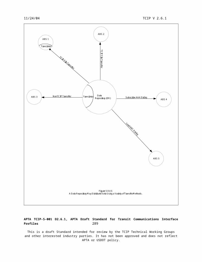
11/24/04 TCIP V 2.6.1
been completely or partially tested during the installation test, however retesting during the acceptance test phase ensures that the system works with everything installed, up and running.
The System Acceptance Test normally also includes a reliability test in which the system must function for an extended period (e.g. 30 days) with a limited number of faults. Faults may be segmented into categories as part of the test procedure definitions. For example in installing a large closed circuit television system, some defined limited number of camera failures may be ‘allowed’ during the reliability test, whereas no failures of the central server during the 30 day period would be allowed.
10 TCIP Communications
10.1 Overview
TCIP communications are the realizations of the 6 networks defined in section 4.2. These networks generally fall into four major categories: Fixed point to fixed point communications Wireless wideband communications Wide area (mobile) communications – public networks Wide area (mobile) communications – private networks
Agencies may implement many variations on these networks without impacting TCIP conformance. The descriptions below of these four network types are generalized and informative only.
10.2 Fixed Point to Point Communications
These communications are both wide-area and local-area, and usually tied to Internet technologies. Local area networks are usually based on TCP/IP or UDP/IP over Ethernet or token ring networks. Local area networks may be extended over a wide area (between facilities) using a variety of fiber optic and wire-based technologies, or using leased communications from public carriers (phone companies). Figure 10.2 depicts a typical fixed point to point communications networks.
APTA TCIP-S-001 D2.6.1, APTA Draft Standard for Transit Communications Interface Profiles 291
This is a draft Standard intended for review by the TCIP Technical Working Groups and other interested industry parties. It has not been approved and does not reflect APTA or USDOT policy.

11/24/04 TCIP V 2.6.1
Facility A
Facility D
Facility CFacility B
BusinessSystem #1
SONETFirewall
BusinessSystem #3
BusinessSystem # 2
BusinessSystem #9
BusinessSystem #8
Frame RelayFirewall
Frame RelayFirewallSONET
BusinessSystem #7
BusinessSystem #6
SONET
BusinessSystem #5
BusinessSystem # 4
Internet ServiceProvider
Ethernet
Ethernet
EthernetEthernet
TelephoneCompany
Fiber
T-1
Figure 10.2Generic Transit Agency Fixed Point to Point Network
FiberFiber
292

11/24/2004 TCIP V 2.6.1
Figure 10.2 depicts an agency which provides access to its business systems via the Internet via a single firewall in facility A. Facilities A-C are connected by a SONET fiber loop which provides a level of redundancy, and protection against fiber failures. Communications within each facility use Ethernet LANs, however the example could have used token ring communications instead. Communications to/from facility D are via a telephone company provided frame relay connection. Each LAN in the diagram could have workstations connected (not shown) along with a variety of hubs, routers, and switches within the Ethernet LAN.
TCIP communications, as well as data communications defined by other standards, can be exchanged over all of this fixed communications infrastructure. For example Business Systems 1 and 8 could be executing a TCIP dialog, while business systems 3 and 5 are performing a TCIP file transfer, and email could simultaneously being sent between workstations and business system #4 functioning as a mail server. Similarly customers using internet appliances might be accessing one of the business systems using an Internet appliance.
10.3 Wireless Wideband Communications
A variety of wireless wideband technologies are available in the market today. Most of these offerings extend high-speed TCP/IP or UDP/IP communications from a LAN to a workstation, computer or another LAN over a wireless link. Most of these products provide short range communications (less than 1 mile). These communications networks are often termed “wireless LANs”.
Wireless LANs provide portable and mobile users with high-speed access to agency business systems which facilitates the unteathered use of applications requiring large verbose data transfers (such as XML). Transit agency use this technology extensively in and around garage areas. In these areas, wireless LANs enable data loads and unloads to/from PTVs, SPVs, and TMVs.
Figure 10.3 depicts a Wireless LAN configuration.
APTA TCIP-S-001 D2.6.1, APTA Draft Standard for Transit Communications Interface Profiles 293
This is a draft Standard intended for review by the TCIP Technical Working Groups and other interested industry parties. It has not been approved and does not reflect APTA or USDOT policy.

11/24/2004 TCIP V 2.6.1
Garage Facility
WirelessAccess PointFirewall
BusinessSystem #2
BusinessSystem #1
WirelessNetworkAdapter
WirelessNetworkAdapter
SPV
WirelessNetworkAdapterTMV
Figure 10.3Transit Agency Wireless LAN Typical Configuration
10.4 Wide Area (Mobile) Communications – Public Networks
Transit agencies require data communications with enroute PTVs, SPVs, and TMVs. The communications may be provided via private networks (see section 10.5), or via a public network. Public networks generally offer a connection for TCP/IP or UDP/IP traffic over a wide area. The public network is shared with other non-transit users. The predominant public networks are based on cell phone technology. Public wireless service is provided on a for-fee basis. The calculation of fees varies widely by carrier, geographical area, and ‘plan’ offered by the carrier.
Agencies electing to use public networks gain the advantages of not needing to develop and maintain their own wireless infrastructure, but have little control over the performance or operations of those networks.
Figure 10.4 depicts a typical agency configuration using a public network.
APTA TCIP-S-001 D2.6.1, APTA Draft Standard for Transit Communications Interface Profiles 294
This is a draft Standard intended for review by the TCIP Technical Working Groups and other interested industry parties. It has not been approved and does not reflect APTA or USDOT policy.

11/24/2004 TCIP V 2.6.1
Garage Facility
Firewall
BusinessSystem #2
BusinessSystem #1
WirelessNetworkAdapter
WirelessNetworkAdapter
SPV
WirelessNetworkAdapterTMV
Figure 10.4
Transit Agency Public Network Typical Configuration
ServiceProvider(carrier)
10.5 Wide Area (Mobile) Communications – Private Networks
Private data networks are usually comprised of: Agency-owned base and mobile radios Radio modems associated with each radio Communications circuits linking base stations with central Centrally located communications manager and/or polling controller Agency licensed radio channels
Agency-owned private radio networks allow the agency to exercise significant control over their wide area mobile networks. Agencies can adjust antenna types, aim and configuration, power levels, etc. Agency-owned networks are maintained by the agency or contractor, providing some control over this aspect of the network as well.
Transit agency private data radio networks are usually polled networks. The mobile radio may be shared between voice and data necessitating a mode change when switching between voice and data. Due to limited private radio channel allocations from the FCC, it is necessary to optimize the communications for a limited capacity network shared by many users within the transit agency. Typically messages are sent in some type of compressed or packed format across the radio channel. The communications protocol itself may be tailored to provide frequently changing information in an efficient format. Annex J defines such a protocol for transit. This protocol is available for use by interested agencies, but is NOT required to achieve TCIP conformance. Figure 10.5 A-B depicts a private radio system with separate data and voice radios.
APTA TCIP-S-001 D2.6.1, APTA Draft Standard for Transit Communications Interface Profiles 295
This is a draft Standard intended for review by the TCIP Technical Working Groups and other interested industry parties. It has not been approved and does not reflect APTA or USDOT policy.

11/24/2004 TCIP V 2.6.1
VLURF ModemMobile Radio
CAD/AVLSystem
PollingController
Base Radio
Base Radio
Figure 10.5.ATypcial Transit Polled Private Data Radio System
APTA TCIP-S-001 D2.6.1, APTA Draft Standard for Transit Communications Interface Profiles 296
This is a draft Standard intended for review by the TCIP Technical Working Groups and other interested industry parties. It has not been approved and does not reflect APTA or USDOT policy.

11/24/2004 TCIP V 2.6.1
OperatorHeadset/
Microphone
Annunciatior
Mobile Radio
CommunicationsConsole
CommunicationsController
Base Radio
Base Radio
Figure 10.5.BTypical Transit Private Voice Radio SystemCommunications
Console
APTA TCIP-S-001 D2.6.1, APTA Draft Standard for Transit Communications Interface Profiles 297
This is a draft Standard intended for review by the TCIP Technical Working Groups and other interested industry parties. It has not been approved and does not reflect APTA or USDOT policy.