˘ ˇ ) - siemens ag · abb aeg-modicon bosch turk etc. series 500 base with 500 profibus-dp rbc...
TRANSCRIPT

������ ��������
��������)�����
�%�$���"'�
��"'� ��%%�!� (��'!��$���������������#"�����&�#"
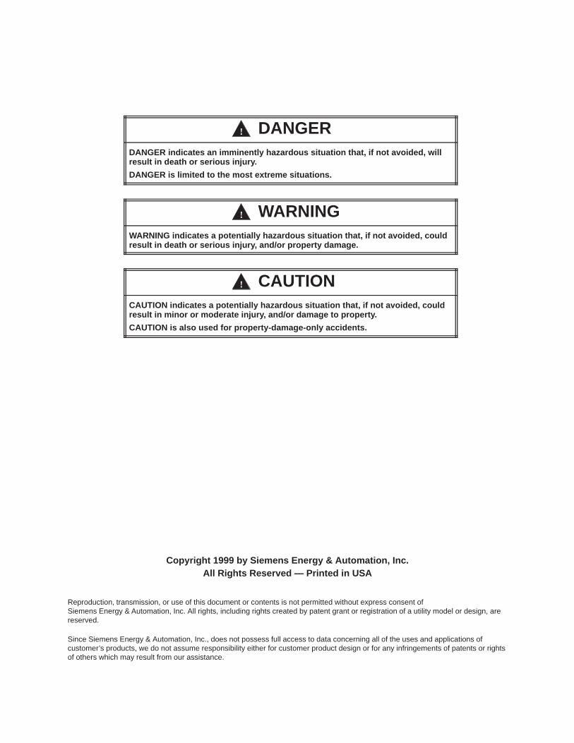
! DANGERDANGER indicates an imminently hazardous situation that, if not avoided, willresult in death or serious injury.
DANGER is limited to the most extreme situations.
! WARNINGWARNING indicates a potentially hazardous situation that, if not avoided, couldresult in death or serious injury, and/or property damage.
! CAUTIONCAUTION indicates a potentially hazardous situation that, if not avoided, couldresult in minor or moderate injury, and/or damage to property.
CAUTION is also used for property-damage-only accidents.
Copyright 1999 by Siemens Energy & Automation, Inc.All Rights Reserved — Printed in USA
Reproduction, transmission, or use of this document or contents is not permitted without express consent ofSiemens Energy & Automation, Inc. All rights, including rights created by patent grant or registration of a utility model or design, arereserved.
Since Siemens Energy & Automation, Inc., does not possess full access to data concerning all of the uses and applications ofcustomer’s products, we do not assume responsibility either for customer product design or for any infringements of patents or rightsof others which may result from our assistance.

MANUAL PUBLICATION HISTORY
SIMATIC 505/500 PROFIBUS-DP RBC User ManualOrder Manual Number: Not applicable; manual ships with RBC.
Refer to this history in all correspondence and/or discussion about this manual.
Event Date Description
Original Issue 03/96 Original Issue (2806091–0001)Second Edition 06/99 Second Edition (2806091–0002)

LIST OF EFFECTIVE PAGES
Pages Description Pages Description
Cover/Copyright Second EditionHistory/Effective Pages Second Edition1 — 28 Second Edition
Registration Second Edition

1SIMATIC 505/500 PROFIBUS-DP RBC User Manual
Contents
1 Overview 2. . . . . . . . . . . . . . . . . . . . . . . . . . . . . . . . . . . . . . . . . . . . . . . . . . . . . . . . . . . . . . . . . . . . . . . Features and Functions 2. . . . . . . . . . . . . . . . . . . . . . . . . . . . . . . . . . . . . . . . . . . . . . . . . . . . . . . . . RBC Specifications 2. . . . . . . . . . . . . . . . . . . . . . . . . . . . . . . . . . . . . . . . . . . . . . . . . . . . . . . . . . . . . .
2 Setup and Installation 4. . . . . . . . . . . . . . . . . . . . . . . . . . . . . . . . . . . . . . . . . . . . . . . . . . . . . . . . . . . RBC Placement in Base 4. . . . . . . . . . . . . . . . . . . . . . . . . . . . . . . . . . . . . . . . . . . . . . . . . . . . . . . . . Installing and Removing the RBC 5. . . . . . . . . . . . . . . . . . . . . . . . . . . . . . . . . . . . . . . . . . . . . . . .
3 RBC Ports 6. . . . . . . . . . . . . . . . . . . . . . . . . . . . . . . . . . . . . . . . . . . . . . . . . . . . . . . . . . . . . . . . . . . . . . . RS-232 Port 6. . . . . . . . . . . . . . . . . . . . . . . . . . . . . . . . . . . . . . . . . . . . . . . . . . . . . . . . . . . . . . . . . . . . . PROFIBUS-DP Port 7. . . . . . . . . . . . . . . . . . . . . . . . . . . . . . . . . . . . . . . . . . . . . . . . . . . . . . . . . . . . . . .
4 Output State Selection on the RBC 8. . . . . . . . . . . . . . . . . . . . . . . . . . . . . . . . . . . . . . . . . . . . . . . Selecting Output State (Off/Freeze) on the 505 RBC 8. . . . . . . . . . . . . . . . . . . . . . . . . . . . . . Selecting Output State (Off/Freeze) on the 500 RBC 9. . . . . . . . . . . . . . . . . . . . . . . . . . . . . . Determining Discrete Output State 10. . . . . . . . . . . . . . . . . . . . . . . . . . . . . . . . . . . . . . . . . . . . . . Determining Analog Output State 10. . . . . . . . . . . . . . . . . . . . . . . . . . . . . . . . . . . . . . . . . . . . . . .
5 Dipswitch Options: Baud Rate, Station Address, Status Display Mode 11. . . . . . . . . . . . . . . Dipswitch Options 11. . . . . . . . . . . . . . . . . . . . . . . . . . . . . . . . . . . . . . . . . . . . . . . . . . . . . . . . . . . . . . Baud Rate for the RS-232 Port 13. . . . . . . . . . . . . . . . . . . . . . . . . . . . . . . . . . . . . . . . . . . . . . . . . . . . Assigning the RBC Station Address 13. . . . . . . . . . . . . . . . . . . . . . . . . . . . . . . . . . . . . . . . . . . . . . . Reset Pushbutton 16. . . . . . . . . . . . . . . . . . . . . . . . . . . . . . . . . . . . . . . . . . . . . . . . . . . . . . . . . . . . . . . Resetting the RBC 16. . . . . . . . . . . . . . . . . . . . . . . . . . . . . . . . . . . . . . . . . . . . . . . . . . . . . . . . . . . . . . . Status Display Mode 18. . . . . . . . . . . . . . . . . . . . . . . . . . . . . . . . . . . . . . . . . . . . . . . . . . . . . . . . . . . .
6 Parameters Set by Software 20. . . . . . . . . . . . . . . . . . . . . . . . . . . . . . . . . . . . . . . . . . . . . . . . . . . . . Setting User Parameters for the PROFIBUS-DP RBC 20. . . . . . . . . . . . . . . . . . . . . . . . . . . . . . . . . Discrete I/O Interval 20. . . . . . . . . . . . . . . . . . . . . . . . . . . . . . . . . . . . . . . . . . . . . . . . . . . . . . . . . . . . . Word I/O Update Factor 20. . . . . . . . . . . . . . . . . . . . . . . . . . . . . . . . . . . . . . . . . . . . . . . . . . . . . . . . 50X Ignore Mismatch Mode 20. . . . . . . . . . . . . . . . . . . . . . . . . . . . . . . . . . . . . . . . . . . . . . . . . . . . . 50X RS-232 Comm Port 20. . . . . . . . . . . . . . . . . . . . . . . . . . . . . . . . . . . . . . . . . . . . . . . . . . . . . . . . . .
7 Diagnostic Data Reported by the RBC 21. . . . . . . . . . . . . . . . . . . . . . . . . . . . . . . . . . . . . . . . . . . . PROFIBUS-DP Diagnostic Bytes 21. . . . . . . . . . . . . . . . . . . . . . . . . . . . . . . . . . . . . . . . . . . . . . . . . . .
8 Upgrading the Operating System 26. . . . . . . . . . . . . . . . . . . . . . . . . . . . . . . . . . . . . . . . . . . . . . . . Overview 26. . . . . . . . . . . . . . . . . . . . . . . . . . . . . . . . . . . . . . . . . . . . . . . . . . . . . . . . . . . . . . . . . . . . . . . Download Instructions 27. . . . . . . . . . . . . . . . . . . . . . . . . . . . . . . . . . . . . . . . . . . . . . . . . . . . . . . . . . Technical Assistance 28. . . . . . . . . . . . . . . . . . . . . . . . . . . . . . . . . . . . . . . . . . . . . . . . . . . . . . . . . . . .
2 SIMATIC 505/500 PROFIBUS-DP RBC User Manual
1 Overview
The SIMATIC� 505 PROFIBUS-DP Remote Base Controller (RBC),PPX:505–6870, allows a Series 505� I/O base to function as a slave node ona DP I/O channel that complies with the PROFIBUS standard (DIN 19245,Part 3). The SIMATIC 500 PROFIBUS-DP Remote Base Controller (RBC),PPX:500–6870, allows a Series 500� I/O base to function as a slave node ona DP I/O channel that complies with the PROFIBUS standard.
The 505 and 500 PROFIBUS-DP RBCs offer the following features:
• The RBC is compatible with Siemens S5� and S7�, as well as Series505, masters.
• The 505 RBC can be used in all currently-available Series 505 bases(4-, 8-, 11-, and 16-slot models).
• The 500 RBC can be used in all Series 500 bases (6-, 12-, and 14-slotmodels, or original 8- and 16-slot models with PPX:500–5840 adapter).
• The RBC supports communication speeds from 9.6 Kbaud (maximumcable distance per segment: 1200 m) up to 12 Mbaud (maximum cabledistance per segment: 100 m).
• The LED display shows error codes or current station address.
• A serial port is available for remote programming of the CPU when theRBC is used on a Series 505/500 system.
• The RBC has a field-upgradeable operating system that is stored inflash memory.
• The base where the RBC resides can contain only modules that looklike discrete or analog I/O; Special Function modules like Peerlink orNIMs are not supported.
• CPU commands received from the serial port are restricted to thosethat cannot alter the PROFIBUS-DP I/O configuration.
• A “GSD” file is provided with the RBC to allow configuration by theCOM PROFIBUS configuration utility.
Figure 1 illustrates how the 505 and 500 PROFIBUS-DP RBCs fit into theI/O architecture of a Series 505 system.
The physical and environmental specifications for the 505 PROFIBUS-DPRBC are listed in the SIMATIC 545/555/575 System Manual.
Features andFunctions
RBC Specifications

3SIMATIC 505/500 PROFIBUS-DP RBC User Manual
Series 505 RemoteI/O Channel (1 Mbaud)
PROFIBUS-DPI/O Channel(12 Mbaud)
Third PartyProducts
Series 505 Base with505 PROFIBUS-DP RBC
CPU
C
RBC
RBC
S7 I/O
ET200BBlock I/O
95U/PROFIBUS-DP
ET200U
ET200C
Series 505 Base with RBC
(PPX:505–6851–A/B RBC)
Series 500 Base with RBC
(PPX:500–5114–A RBC)
(PPX:505–6870 RBC)
RBC
Siemens AC/DCMotors and Drives
545/555/575
Notes:The Series 505 remote I/O channel supports up to 15 Series 505/Series 500 remote bases.
The PROFIBUS-DP I/O channel supports up to 112 SIMATIC and third-party DP I/O slaves.
A 575–2104 CPU can support either the 505 I/O channel or the PROFIBUS-DP channel, but not both simultaneously.
The 545–1103/–1105 CPUs support only the PROFIBUS-DP channel, up to 32 SIMATIC and third-party DP I/O slaves, with theoptional PROFIBUS-DP I/O annex card.
AS-Interface Master
Limit SW P/B Solenoid PE Cell
AS-Interface Bus
Allen-BradleyFestoMetlore-ToledoData LogicABBAEG-ModiconBoschTurketc.
Series 500 Base with 500PROFIBUS-DP RBC
(PPX:500–6870 RBC)
RBC
Figure 1 I/O Architecture for Series 505 System
4 SIMATIC 505/500 PROFIBUS-DP RBC User Manual
2 Setup and Installation
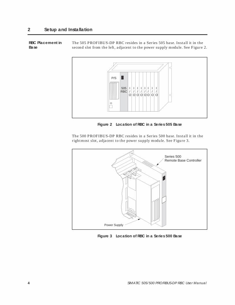
The 505 PROFIBUS-DP RBC resides in a Series 505 base. Install it in thesecond slot from the left, adjacent to the power supply module. See Figure 2.
I/O
I/O
I/O
I/O
I/O
I/O
I/O
I/O
P/S
505RBC
Figure 2 Location of RBC in a Series 505 Base
The 500 PROFIBUS-DP RBC resides in a Series 500 base. Install it in therightmost slot, adjacent to the power supply module. See Figure 3.
Series 500 Remote Base Controller
Power Supply
Figure 3 Location of RBC in a Series 500 Base
RBC Placement inBase

5SIMATIC 505/500 PROFIBUS-DP RBC User Manual
Use the following steps to install the 505–6870 RBC in a Series 505 base orto install the 500–6870 RBC in a Series 500 base.
! WARNINGInstalling or removing an RBC from a powered-up base disrupts your processand can damage the RBC. Disruption of your process can cause death orserious injury to personnel, and/or damage to equipment.
Ensure that all power is disabled before installing or removing the RBC.
! CAUTIONThe RBC is sensitive to, and can be damaged by, electrostatic discharge.
Ensure that personnel make contact with a static-dissipative pad and/or wear agrounded wrist strap when handling the RBC.
1. Verify that all jumper settings on the 505 RBC or the Off/Freeze toggleswitch on the 500 RBC are correct. See Section 4. It is advisable to setthe dipswitch options before installing the module. See Section 5.
2. Disconnect power to the base.
3. Position the RBC so that the bezel is facing you.
4. Grasp the top and bottom of the RBC.
5. Carefully push the RBC into the slot until it mates with the backplaneconnector.
6. Tighten the top and bottom bezel screws.
! CAUTIONSeries 505 RBCs are not designed to be installed in VME bases. Doing soresults in damage to equipment.
Never attempt to install any Series 505 RBC in a VME base.
To remove the RBC, complete the following steps.
1. If attached, remove cables from the RBC.
2. Disconnect power to the base.
3. Loosen the top and bottom bezel screws.
4. Carefully pull the RBC from the base.
Installing andRemoving the RBC
6 SIMATIC 505/500 PROFIBUS-DP RBC User Manual
3 RBC Ports
The 505 and 500 PROFIBUS-DP RBCs have two communication ports, anRS-232 port and a PROFIBUS-DP I/O channel port.
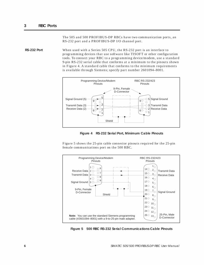
When used with a Series 505 CPU, the RS-232 port is an interface toprogramming devices that use software like TISOFT or other configurationtools. To connect your RBC to a programming device/modem, use a standard9-pin RS-232 serial cable that conforms at a minimum to the pinouts shownin Figure 4. A standard cable that conforms to the minimum requirementsis available through Siemens; specify part number 2601094–8001.
RBC RS-232/423Pinouts
61
95
Programming Device/ModemPinouts
61
95 Signal Ground
Transmit DataReceive Data
Signal Ground (5)
Transmit Data (3)Receive Data (2)
Shield
3
2
32
9-Pin, FemaleD-Connector
Figure 4 RS-232 Serial Port, Minimum Cable Pinouts
Figure 5 shows the 25-pin cable connector pinouts required for the 25-pinfemale communications port on the 500 RBC.
1
2
3
4
5
6
7
8
9
10
11
12
13
14
15
16
17
18
19
20
21
22
23
24
25
Signal Ground
1
2
3
4
5
6
7
8
9
9-Pin, FemaleD-Connector
25-Pin, MaleD-Connector
Note: You can use the standard Siemens programmingcable (#2601094–8001) with a 9-to-25-pin male adapter.
Transmit Data
Receive DataTransmit Data
Receive Data
Signal GroundShield
RBC RS-232/423Pinouts
Programming Device/ModemPinouts
Figure 5 500 RBC RS-232 Serial Communications Cable Pinouts
RS-232 Port

7SIMATIC 505/500 PROFIBUS-DP RBC User Manual
The PROFIBUS-DP port is used to connect the RBC to the PROFIBUS-DPI/O channel. The SIMATIC 545/555/575 System Manual describes how toconnect a 12 Mbaud RS-485 cable to the PROFIBUS-DP port. Figure 6shows the pinout for the PROFIBUS-DP port for the PROFIBUS-DP RBC.
NOTE: Pins 2 and 7 are “No Connect” for the RBC. For some PROFIBUSproducts, these pins are used to provide 24 VDC for powering aprogramming or configuration tool. Such tools are not powered by the RBC;however, it is acceptable for an externally-powered PROFIBUSprogramming or configuration tool to drive pins 2 and 7 to 24 VDC.
1
2
*3
NO CONNECT
TX/RX+
4
5
6
RTS
7 NO CONNECT
*8 TX/RX–
9
Pin Signal
Female 9-Pin D-Connector
* For Pin 3: Terminal B on Siemens connector.* For Pin 8: Terminal A on Siemens connector.
BIAS SUPPLY GND (5)
TX/RX+ (3)TX/RX– (8)
6 1
95
BIAS SUPPLY GND
CHASSIS GND
BIAS SUPPLY +5V
BIAS SUPPLY GND
(D-shell) CHASSIS GND
78
234
Figure 6 PROFIBUS-DP I/O Port Pinouts
! CAUTIONPin 5 (BIAS SUPPLY +5V) and Pin 6 (BIAS SUPPLY GND) on the PROFIBUS-DPconnector are designed to support the PROFIBUS-DP I/O channel only. Thesepins have a limited output power capability of approximately 0.45 W, whichgreatly exceeds the typical PROFIBUS-DP load; however, overloading thesepins may cause internal component damage.
If the pins are overloaded, the PROFIBUS-DP port can be renderednon-functional, requiring the unit to be returned to the factory for repair.
Do not overload the pins on the PROFIBUS-DP connector.
PROFIBUS-DP Port
8 SIMATIC 505/500 PROFIBUS-DP RBC User Manual
4 Output State Selection on the RBC
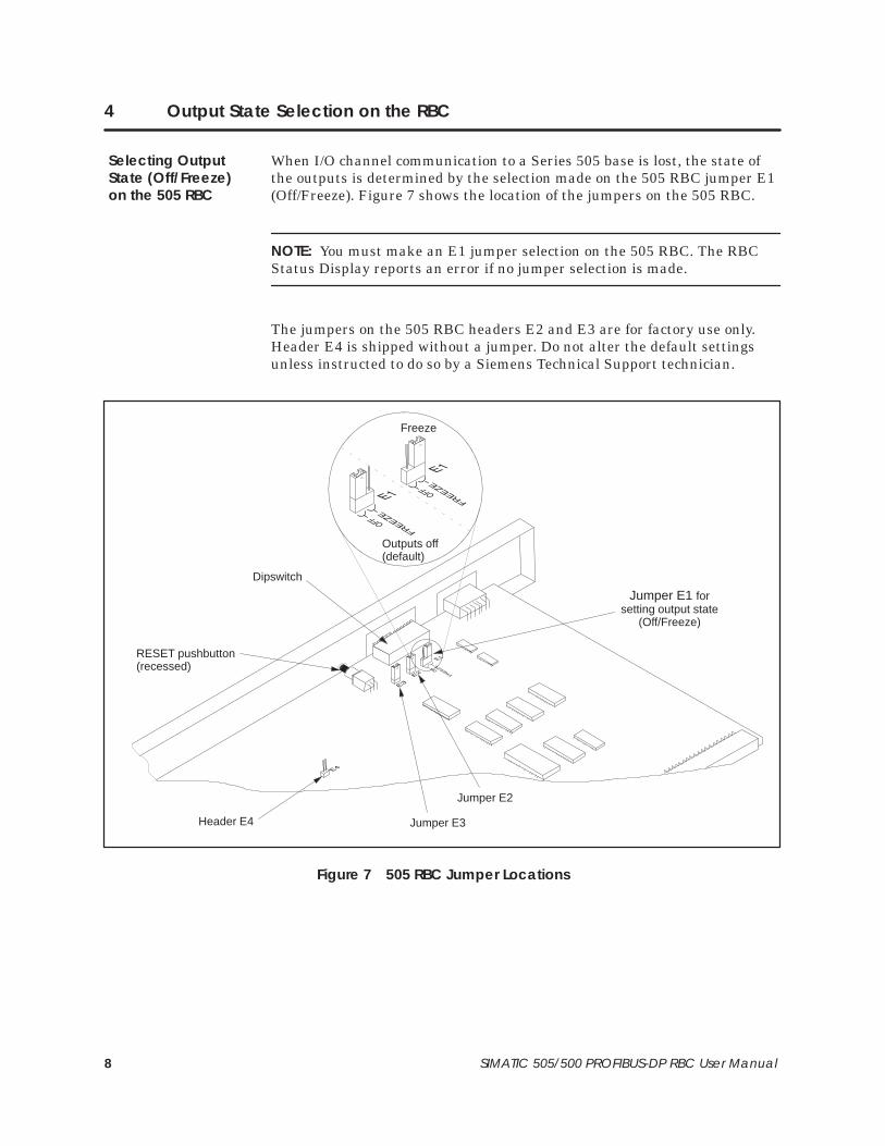
When I/O channel communication to a Series 505 base is lost, the state ofthe outputs is determined by the selection made on the 505 RBC jumper E1(Off/Freeze). Figure 7 shows the location of the jumpers on the 505 RBC.
NOTE: You must make an E1 jumper selection on the 505 RBC. The RBCStatus Display reports an error if no jumper selection is made.
The jumpers on the 505 RBC headers E2 and E3 are for factory use only.Header E4 is shipped without a jumper. Do not alter the default settingsunless instructed to do so by a Siemens Technical Support technician.
Jumper E1 forsetting output state
(Off/Freeze)
Jumper E2
Jumper E3Header E4
RESET pushbutton(recessed)
Dipswitch
Freeze
Outputs off(default)
Figure 7 505 RBC Jumper Locations
Selecting OutputState (Off/Freeze)on the 505 RBC
9SIMATIC 505/500 PROFIBUS-DP RBC User Manual
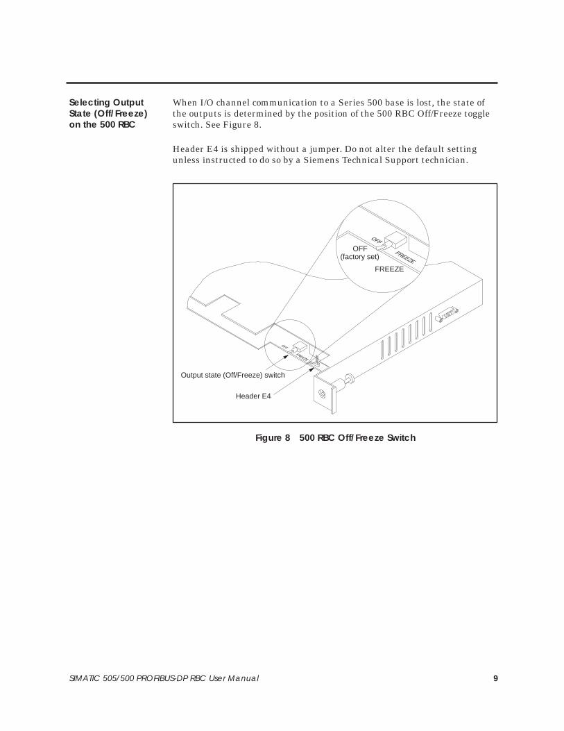
When I/O channel communication to a Series 500 base is lost, the state ofthe outputs is determined by the position of the 500 RBC Off/Freeze toggleswitch. See Figure 8.
Header E4 is shipped without a jumper. Do not alter the default settingunless instructed to do so by a Siemens Technical Support technician.
FREEZE
(factory set)OFF
Header E4
Output state (Off/Freeze) switch
Figure 8 500 RBC Off/Freeze Switch
Selecting OutputState (Off/Freeze)on the 500 RBC

10 SIMATIC 505/500 PROFIBUS-DP RBC User Manual
Output State Selection on the RBC (continued)
For discrete output modules, the state of the outputs is determined solely bythe position of the Off/Freeze jumper E1 on the 505 RBC or the Off/Freezeswitch on the 500 RBC.
For analog/word output modules, the state of the outputs is influenced notonly by the position of the Off/Freeze switch but by the output module’s(Zero/Hold Last Value) selection, if the module has that option. See Table 1.
Table 1 Analog/Word Output States
RBC Off/Freeze Selection Analog/Word ModuleZero/Hold Selection
Analog/WordOutput State
Off Zero Zero*
Off Hold Last Value Last Value
Off – no selection – Last Value
Freeze Zero Last Value
Freeze Hold Last Value Last Value
Freeze – no selection – Last Value
*See the user manual of your analog/word output module for further details.
Notice, in Table 1, that the Freeze option on the RBC overrides the Zeroselection on the analog/word output module; likewise, when Hold Last Valueis selected on the analog/word output module, that selection overrides theOff option on the RBC jumper.
NOTE: If the RBC hardware watchdog timer is activated (by an RBCfailure), the state of the outputs is determined by the output module, withno reference to the RBC’s Off/Freeze setting. Discrete outputs go off (to avalue of zero). Analog/word outputs obey their own Zero/Hold Last Valueselection. If no Zero/Hold Last Value selection is available on the module,the analog/word outputs hold their last value.
DeterminingDiscrete OutputState
DeterminingAnalog OutputState

11SIMATIC 505/500 PROFIBUS-DP RBC User Manual
5 Dipswitch Options: Baud Rate, Station Address, Status Display Mode
You can select the RS-232/423 baud rate, RBC station address, and displaymode of the RBC status display by setting a dipswitch that is accessiblefrom the bezel of the RBC. Figure 9 shows the location of the dipswitch anddipswitch cover on the bezel of the 500 RBC.
0–MODULE READY1–DIAGNOSTIC FAILURE2–MODULE MISMATCH3–NO COMMUNICATIONS4–NO OPERATIONAL FIRMWARE5–NO HOLD MODE SELECTION6–INVALID RS–232 BAUD RATE7–NO I/O CONFIGURATION8–WATCHDOG TIMER EXPIREDC–SEE MANUAL
RESET
Dipswitchcover
RESET pushbutton(recessed)
� �
Dipswitch block(located behind door)
Set RS-232/423Serial Port Baud RateSee Table 2
Set RBC Station AddressSee Table 3
Set Status Display Mode
Spare
Status display
Siemens
PROFIBUSREMOTE
BASECONTROLLER
STATUS
MODEL500-6870
Figure 9 500 PROFIBUS-DP Remote Base Controller
Dipswitch Options

12 SIMATIC 505/500 PROFIBUS-DP RBC User Manual
Dipswitch Options (continued)
Figure 10 shows the location of the dipswitch and dipswitch cover on thebezel of the 505 RBC.
505 PROFIBUS-DPREMOTE BASECONTROLLER
505-6870
STATUS0–MODULE READY1–DIAGNOSTIC FAILURE2–MODULE MISMATCH3–NO COMMUNICATIONS4–NO OPERATIONAL FIRMWARE5–NO HOLD MODE SELECTION6–INVALID RS-232 BAUD RATE7–NO I/O CONFIGURATION8–WATCHDOG TIMER EXPIREDC–SEE MANUAL
RS-232
RESET
RS-232/423serial port(male)
Dipswitchcover
RESET pushbutton(recessed)
� �
Dipswitch block(located behind door)
Set RS-232/423Serial Port Baud RateSee Table 2
Set RBC Station AddressSee Table 3
Set Status Display Mode
Spare
PROFIBUS-DP
Status display
I/O channel port(female)
Figure 10 505 PROFIBUS-DP Remote Base Controller

13SIMATIC 505/500 PROFIBUS-DP RBC User Manual
Switches 1 through 3 on the dipswitch control the baud rate of theRS-232/423 port. Table 2 lists the baud rates available.
Invalid selections cause the RBC to report an error on the Status Displayand cause the RS-232/423 port to default to 9600 baud.
The RS-232/423 baud rate switch settings are read only on power-up orafter pressing the reset button.
NOTE: The RS-232 port is disabled by default. To enable the port, changethe default parameter of the module in COM PROFIBUS. (See Table 5.)
Table 2 RS-232 Port Baud Rate Settings
Baud Rate Switch 1 Switch 2 Switch 3
38400 0 0 1
19200 1 1 1
9600 1 1 0
2400 1 0 0
1200 0 1 0
300 0 0 0
INVALID 0 1 1
INVALID 1 0 1
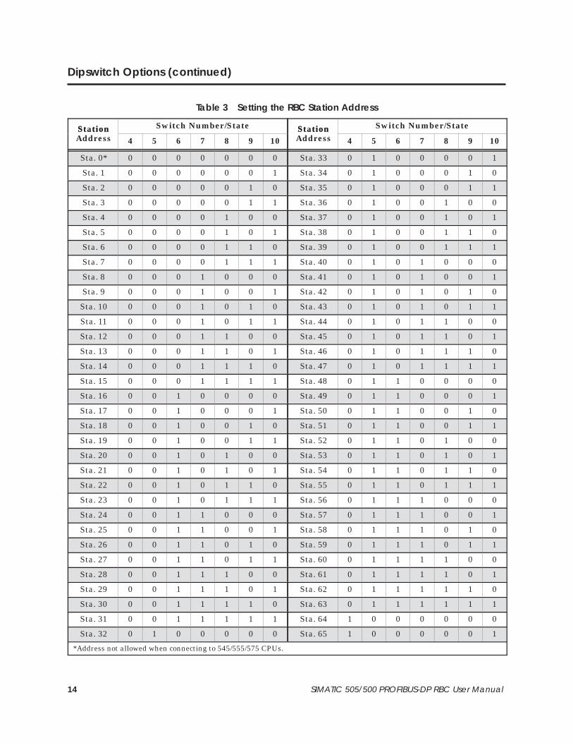
Switches 4 through 10 on the dipswitch are used to assign a station addressto the RBC for identification in the PROFIBUS-DP I/O channel. Eachstation in the PROFIBUS-DP I/O channel must be uniquely numbered. Thestation address is assigned as a binary number, with SW10 as the LeastSignificant Bit (LSB). Table 3 shows how to set the dipswitch to a stationaddress between 0 and 125 (the valid range of station addresses).
The station address switch settings are read only on power-up or afterpressing the reset button.
! WARNINGPressing the RESET button when the system is operating causes the RBC to belogged off the system and may change the output states of the output modulesin the base. Inadvertently logging the RBC off the system or changing outputstates can cause unpredictable process operation.
Unpredictable process operation can result in death or serious injury topersonnel, and/or damage to equipment.
Do not push the reset button unless you intend to log the RBC off the system.
Baud Rate for theRS-232 Port
Assigning the RBCStation Address
14 SIMATIC 505/500 PROFIBUS-DP RBC User Manual
Dipswitch Options (continued)
Table 3 Setting the RBC Station Address
StationA ss
Switch Number/State StationA ss
Switch Number/StateStationAddress 4 5 6 7 8 9 10
StationAddress 4 5 6 7 8 9 10
Sta. 0* 0 0 0 0 0 0 0 Sta. 33 0 1 0 0 0 0 1
Sta. 1 0 0 0 0 0 0 1 Sta. 34 0 1 0 0 0 1 0
Sta. 2 0 0 0 0 0 1 0 Sta. 35 0 1 0 0 0 1 1
Sta. 3 0 0 0 0 0 1 1 Sta. 36 0 1 0 0 1 0 0
Sta. 4 0 0 0 0 1 0 0 Sta. 37 0 1 0 0 1 0 1
Sta. 5 0 0 0 0 1 0 1 Sta. 38 0 1 0 0 1 1 0
Sta. 6 0 0 0 0 1 1 0 Sta. 39 0 1 0 0 1 1 1
Sta. 7 0 0 0 0 1 1 1 Sta. 40 0 1 0 1 0 0 0
Sta. 8 0 0 0 1 0 0 0 Sta. 41 0 1 0 1 0 0 1
Sta. 9 0 0 0 1 0 0 1 Sta. 42 0 1 0 1 0 1 0
Sta. 10 0 0 0 1 0 1 0 Sta. 43 0 1 0 1 0 1 1
Sta. 11 0 0 0 1 0 1 1 Sta. 44 0 1 0 1 1 0 0
Sta. 12 0 0 0 1 1 0 0 Sta. 45 0 1 0 1 1 0 1
Sta. 13 0 0 0 1 1 0 1 Sta. 46 0 1 0 1 1 1 0
Sta. 14 0 0 0 1 1 1 0 Sta. 47 0 1 0 1 1 1 1
Sta. 15 0 0 0 1 1 1 1 Sta. 48 0 1 1 0 0 0 0
Sta. 16 0 0 1 0 0 0 0 Sta. 49 0 1 1 0 0 0 1
Sta. 17 0 0 1 0 0 0 1 Sta. 50 0 1 1 0 0 1 0
Sta. 18 0 0 1 0 0 1 0 Sta. 51 0 1 1 0 0 1 1
Sta. 19 0 0 1 0 0 1 1 Sta. 52 0 1 1 0 1 0 0
Sta. 20 0 0 1 0 1 0 0 Sta. 53 0 1 1 0 1 0 1
Sta. 21 0 0 1 0 1 0 1 Sta. 54 0 1 1 0 1 1 0
Sta. 22 0 0 1 0 1 1 0 Sta. 55 0 1 1 0 1 1 1
Sta. 23 0 0 1 0 1 1 1 Sta. 56 0 1 1 1 0 0 0
Sta. 24 0 0 1 1 0 0 0 Sta. 57 0 1 1 1 0 0 1
Sta. 25 0 0 1 1 0 0 1 Sta. 58 0 1 1 1 0 1 0
Sta. 26 0 0 1 1 0 1 0 Sta. 59 0 1 1 1 0 1 1
Sta. 27 0 0 1 1 0 1 1 Sta. 60 0 1 1 1 1 0 0
Sta. 28 0 0 1 1 1 0 0 Sta. 61 0 1 1 1 1 0 1
Sta. 29 0 0 1 1 1 0 1 Sta. 62 0 1 1 1 1 1 0
Sta. 30 0 0 1 1 1 1 0 Sta. 63 0 1 1 1 1 1 1
Sta. 31 0 0 1 1 1 1 1 Sta. 64 1 0 0 0 0 0 0
Sta. 32 0 1 0 0 0 0 0 Sta. 65 1 0 0 0 0 0 1
*Address not allowed when connecting to 545/555/575 CPUs.
15SIMATIC 505/500 PROFIBUS-DP RBC User Manual
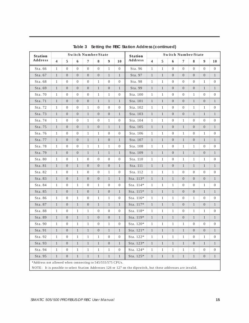
Table 3 Setting the RBC Station Address (continued)
StationA ss
Switch Number/State StationA ss
Switch Number/StateStationAddress 4 5 6 7 8 9 10
StationAddress 4 5 6 7 8 9 10
Sta. 66 1 0 0 0 0 1 0 Sta. 96 1 1 0 0 0 0 0
Sta. 67 1 0 0 0 0 1 1 Sta. 97 1 1 0 0 0 0 1
Sta. 68 1 0 0 0 1 0 0 Sta. 98 1 1 0 0 0 1 0
Sta. 69 1 0 0 0 1 0 1 Sta. 99 1 1 0 0 0 1 1
Sta. 70 1 0 0 0 1 1 0 Sta. 100 1 1 0 0 1 0 0
Sta. 71 1 0 0 0 1 1 1 Sta. 101 1 1 0 0 1 0 1
Sta. 72 1 0 0 1 0 0 0 Sta. 102 1 1 0 0 1 1 0
Sta. 73 1 0 0 1 0 0 1 Sta. 103 1 1 0 0 1 1 1
Sta. 74 1 0 0 1 0 1 0 Sta. 104 1 1 0 1 0 0 0
Sta. 75 1 0 0 1 0 1 1 Sta. 105 1 1 0 1 0 0 1
Sta. 76 1 0 0 1 1 0 0 Sta. 106 1 1 0 1 0 1 0
Sta. 77 1 0 0 1 1 0 1 Sta. 107 1 1 0 1 0 1 1
Sta. 78 1 0 0 1 1 1 0 Sta. 108 1 1 0 1 1 0 0
Sta. 79 1 0 0 1 1 1 1 Sta. 109 1 1 0 1 1 0 1
Sta. 80 1 0 1 0 0 0 0 Sta. 110 1 1 0 1 1 1 0
Sta. 81 1 0 1 0 0 0 1 Sta. 111 1 1 0 1 1 1 1
Sta. 82 1 0 1 0 0 1 0 Sta. 112 1 1 1 0 0 0 0
Sta. 83 1 0 1 0 0 1 1 Sta. 113* 1 1 1 0 0 0 1
Sta. 84 1 0 1 0 1 0 0 Sta. 114* 1 1 1 0 0 1 0
Sta. 85 1 0 1 0 1 0 1 Sta. 115* 1 1 1 0 0 1 1
Sta. 86 1 0 1 0 1 1 0 Sta. 116* 1 1 1 0 1 0 0
Sta. 87 1 0 1 0 1 1 1 Sta. 117* 1 1 1 0 1 0 1
Sta. 88 1 0 1 1 0 0 0 Sta. 118* 1 1 1 0 1 1 0
Sta. 89 1 0 1 1 0 0 1 Sta. 119* 1 1 1 0 1 1 1
Sta. 90 1 0 1 1 0 1 0 Sta. 120* 1 1 1 1 0 0 0
Sta. 91 1 0 1 1 0 1 1 Sta. 121* 1 1 1 1 0 0 1
Sta. 92 1 0 1 1 1 0 0 Sta. 122* 1 1 1 1 0 1 0
Sta. 93 1 0 1 1 1 0 1 Sta. 123* 1 1 1 1 0 1 1
Sta. 94 1 0 1 1 1 1 0 Sta. 124* 1 1 1 1 1 0 0
Sta. 95 1 0 1 1 1 1 1 Sta. 125* 1 1 1 1 1 0 1
*Address not allowed when connecting to 545/555/575 CPUs.
NOTE: It is possible to select Station Addresses 126 or 127 on the dipswitch, but these addresses are invalid.

16 SIMATIC 505/500 PROFIBUS-DP RBC User Manual
Dipswitch Options (continued)
The RESET pushbutton on the front of the RBC is deliberately recessed toprevent accidental activation. When you press this button, a global reset isimmediately performed on the RBC. After completing reset, the RBCassumes the RS-232 baud rate stipulated by the setting of switches 1through 3 on the dipswitch, and the station address indicated by switches 4through 10.
! WARNINGPressing the RESET button when the system is operating causes the RBC to belogged off the system. When the RBC is logged off, inputs and outputsassociated with the base are affected. See the documentation for your systemmaster to find out how the master handles I/O when the RBC logs off. If you donot take the condition of your inputs and outputs into account, logging the RBCoff the system can cause unpredictable process operation.
Unpredictable process operation can cause death or serious injury topersonnel, and/or damage to equipment.
Do not reset your RBC unless you understand and are prepared for theconsequences.
The following actions take place when an RBC is reset.
• The CPU logs the RBC off the system and sets the image registerpoints which represent the inputs from this RBC’s base to zero. Theimage register is zeroed out until the RBC completes reset and resumescommunication with the CPU. If this occurs while the system isoperating, depending on your RLL program, turning these inputs offcould affect other base outputs.
• From the assertion of reset until the RBC completes the reset andresumes communication with the CPU, the state of the outputs on thisRBC’s base is determined by the output module, with no reference tothe RBC’s Off/Freeze setting. Discrete outputs go off (to a value of zero).Analog/word outputs obey their own Zero/Hold Last Value selection. Ifno Zero/Hold Last Value selection is available on the module, theanalog/word outputs hold their last value.
• If the station address you assign to the RBC (by setting the dipswitch)inadvertently duplicates an address already in use by another slave onthe I/O channel, then when the RBC completes its reset and attemptsto communicate, identifying itself with the new station address, theother slave may be logged off the system. Intermittent operation couldoccur as long as the two slaves are set to the same station address.
Reset Pushbutton
Resetting the RBC

17SIMATIC 505/500 PROFIBUS-DP RBC User Manual
When the CPU logs an RBC off the system, it sets a corresponding bit in oneof the status words that are available to your RLL program. Your RLLprogram can use these bits to detect the loss of the RBC and control theoutputs of other bases as appropriate for your application. For details aboutstatus words and more information about programming, refer to theSIMATIC 545/555/575 Programming Reference User Manual.

18 SIMATIC 505/500 PROFIBUS-DP RBC User Manual
Dipswitch Options (continued)
Switch 11 on the dipswitch controls the display mode of the RBC StatusDisplay to show either station address or module status.
• When switch 11 is set to 1, the station address of the RBC is displayedas a three-digit number, one digit at a time. The display goes blank fora short period of time between each digit and for a long period after thelast digit. For example, if the RBC station address is 18, it will bedisplayed according to this pattern:
0 (short pause) → 1 (short pause) → 8 (long pause)
0 (short pause) → 1 (short pause) → 8 (long pause) . . .
The three-digit pattern repeats until the mode is changed.
• When switch 11 is set to 0, the status of the RBC is displayed,according to the codes shown in Table 4.
NOTE: When switch 11 is set to display the RBC status, a decimal point onthe status display indicates that the 50X Ignore Mismatch Mode parameteris enabled. The point appears before the status code, as shown below.
If the 50X Ignore Mismatch Mode is disabled (the default value thatconforms to the DP standard), the RBC status display does not show adecimal point. For more information about this parameter, see page 20.
The Status Display mode switch is read periodically during operation. Theswitch may be changed at any time.
Table 4 PROFIBUS-DP RBC Status Codes
Display Definition Communicationsto this RBC Comment/Action
0 Module Ready OK Fully operational. No errors detected.Action: None.
1 Diagnostic Failure None
Serious malfunction.Action: Place the system in a safe state andconsult Siemens Technical Support. (In theU.S.A., call 423–461–2522.)
2 Module Mismatch OK
I/O modules installed in this base do notmatch the expected configuration in thePROFIBUS-DP master.Action: Compare the actual configuration ofthe base against the configuration expectedby the PROFIBUS-DP master.
Status DisplayMode

19SIMATIC 505/500 PROFIBUS-DP RBC User Manual
Table 4 PROFIBUS-DP RBC Status Codes (continued)
Display Definition Communicationsto this RBC Comment/Action
3 No Communications None
The RBC detects no PROFIBUS-DP I/Ochannel activity.Action: Place the system in a safe state andcheck the connection to the PROFIBUS-DPI/O channel. Ensure that otherPROFIBUS-DP I/O channel devices arepowered and not reporting errors.
4 No Operational Firmware NoneFirmware is missing.Action: Download new firmware into FlashMemory.
5 No Hold Mode Selection OK
[505 RBC only] Jumper E1 is missing ornot recognized.Action: Install jumper on header E1.Default: The RBC continues to operate witha missing jumper; if communication is lost,outputs will be driven to Off setting.
6 Invalid RS-232/423 Baud Rate OK
Improper dipswitch selection for RS-232baud rate.Action: Set the dipswitch to valid RS-232baud rate.Default: The RBC continues to operate withan improper dipswitch setting; it uses anRS-232 baud rate of 9600.
7 No I/O Configuration Not Ready
PROFIBUS-DP master and RBC did notcomplete I/O channel initialization.Probable causes: The station address isincorrect, or the I/O modules installed inthis base do not match the I/O configurationexpected by the PROFIBUS-DP master.Action: Check for and if necessary select avalid station address. Compare the actualconfiguration of the base against theconfiguration expected by thePROFIBUS-DP master.
8 Watchdog Timer Expired None
Hardware watchdog timeout thatimmediately resets the RBC.Action: Serious malfunction. Place thesystem in a safe state and consult SiemensTechnical Support. (In the U.S.A., call423–461–2522.)
C Consult Siemens TechnicalSupport Not Ready
Serious malfunction.Action: Place the system in a safe state andconsult Siemens Technical Support. (In theU.S.A., call 423–461–2522.)
–blank– Blank, No Code Displayed None
No power to base, or serious malfunction.Action: Check power to base. If base power isOK, place the system in a safe state andconsult Siemens Technical Support. (In theU.S.A., call 423–461–2522.)
20 SIMATIC 505/500 PROFIBUS-DP RBC User Manual
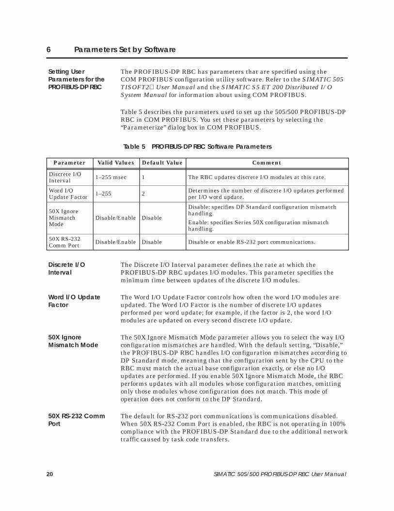
6 Parameters Set by Software
The PROFIBUS-DP RBC has parameters that are specified using theCOM PROFIBUS configuration utility software. Refer to the SIMATIC 505TISOFT2 User Manual and the SIMATIC S5 ET 200 Distributed I/OSystem Manual for information about using COM PROFIBUS.
Table 5 describes the parameters used to set up the 505/500 PROFIBUS-DPRBC in COM PROFIBUS. You set these parameters by selecting the“Parameterize” dialog box in COM PROFIBUS.
Table 5 PROFIBUS-DP RBC Software Parameters
Parameter Valid Values Default Value Comment
Discrete I/OInterval 1–255 msec 1 The RBC updates discrete I/O modules at this rate.
Word I/OUpdate Factor 1–255 2 Determines the number of discrete I/O updates performed
per I/O word update.
50X IgnoreMismatchMode
Disable/Enable Disable
Disable: specifies DP Standard configuration mismatchhandling.
Enable: specifies Series 50X configuration mismatchhandling.
50X RS-232Comm Port Disable/Enable Disable Disable or enable RS-232 port communications.
The Discrete I/O Interval parameter defines the rate at which thePROFIBUS-DP RBC updates I/O modules. This parameter specifies theminimum time between updates of the discrete I/O modules.
The Word I/O Update Factor controls how often the word I/O modules areupdated. The Word I/O Factor is the number of discrete I/O updatesperformed per word update; for example, if the factor is 2, the word I/Omodules are updated on every second discrete I/O update.
The 50X Ignore Mismatch Mode parameter allows you to select the way I/Oconfiguration mismatches are handled. With the default setting, “Disable,”the PROFIBUS-DP RBC handles I/O configuration mismatches according toDP Standard mode, meaning that the configuration sent by the CPU to theRBC must match the actual base configuration exactly, or else no I/Oupdates are performed. If you enable 50X Ignore Mismatch Mode, the RBCperforms updates with all modules whose configuration matches, omittingonly those modules whose configuration does not match. This mode ofoperation does not conform to the DP Standard.
The default for RS-232 port communications is communications disabled.When 50X RS-232 Comm Port is enabled, the RBC is not operating in 100%compliance with the PROFIBUS-DP Standard due to the additional networktraffic caused by task code transfers.
Setting UserParameters for thePROFIBUS-DP RBC
Discrete I/OInterval
Word I/O UpdateFactor
50X IgnoreMismatch Mode
50X RS-232 CommPort
21SIMATIC 505/500 PROFIBUS-DP RBC User Manual
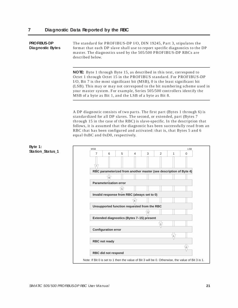
7 Diagnostic Data Reported by the RBC
The standard for PROFIBUS-DP I/O, DIN 19245, Part 3, stipulates theformat that each DP slave shall use to report specific diagnostics to the DPmaster. The diagnostics used by the 505/500 PROFIBUS-DP RBCs aredescribed below.
NOTE: Byte 1 through Byte 15, as described in this text, correspond toOctet 1 through Octet 15 in the PROFIBUS standard. For PROFIBUS-DPI/O, Bit 7 is the most significant bit (MSB), 0 is the least significant bit(LSB). This may or may not correspond to the bit numbering scheme used inyour master system. For example, Series 505/500 controllers identify theMSB of a byte as Bit 1, and the LSB of a byte as Bit 8.
A DP diagnostic consists of two parts. The first part (Bytes 1 through 6) isstandardized for all DP slaves. The second, or extended, part (Bytes 7through 15 in the case of the RBC) is slave-specific. In the description thatfollows, it is assumed that the diagnostic has been successfully read from anRBC that has been configured and activated: that is, that Bytes 5 and 6equal 0xBC and 0xD0, respectively.
RBC parameterized from another master (see description of Byte 4)
Invalid response from RBC (always set to 0)
Parameterization error
Extended diagnostics (Bytes 7–15) present
Unsupported function requested from the RBC
RBC not ready
Configuration error
RBC did not respond
MSB LSB
7
6
5
4
3
2
1
0
01234567
Note: If Bit 0 is set to 1 then the value of Bit 3 will be 0. Otherwise, the value of Bit 3 is 1.
PROFIBUS-DPDiagnostic Bytes
Byte 1:Station_Status_1
22 SIMATIC 505/500 PROFIBUS-DP RBC User Manual
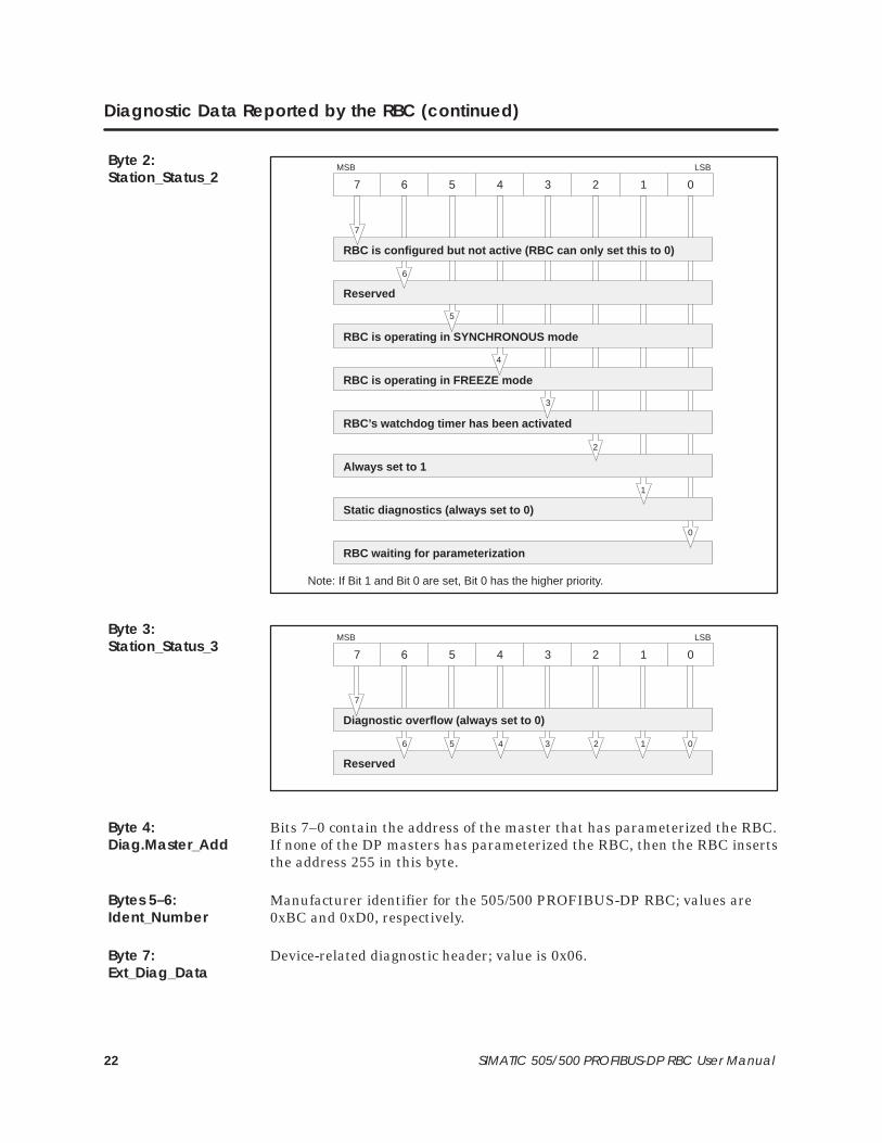
Diagnostic Data Reported by the RBC (continued)
RBC is configured but not active (RBC can only set this to 0)
RBC is operating in SYNCHRONOUS mode
Reserved
RBC’s watchdog timer has been activated
RBC is operating in FREEZE mode
Static diagnostics (always set to 0)
Always set to 1
RBC waiting for parameterization
MSB LSB
7
6
5
4
3
2
1
0
01234567
Note: If Bit 1 and Bit 0 are set, Bit 0 has the higher priority.
Reserved
MSB LSB
6
01234567
5 4 3 2 1 0
Diagnostic overflow (always set to 0)
7
Bits 7–0 contain the address of the master that has parameterized the RBC.If none of the DP masters has parameterized the RBC, then the RBC insertsthe address 255 in this byte.
Manufacturer identifier for the 505/500 PROFIBUS-DP RBC; values are0xBC and 0xD0, respectively.
Device-related diagnostic header; value is 0x06.
Byte 2:Station_Status_2
Byte 3:Station_Status_3
Byte 4:Diag.Master_Add
Bytes 5–6:Ident_Number
Byte 7:Ext_Diag_Data

23SIMATIC 505/500 PROFIBUS-DP RBC User Manual
Remote port request pending
0
MSB LSB
7
01234567
Reserved
6 5 4 3 2 1
Reserved.
Slot 8 is mismatched type
Slot 6 is mismatched type
Slot 7 is mismatched type
Slot 4 is mismatched type
Slot 5 is mismatched type
Slot 2 is mismatched type
Slot 3 is mismatched type
Slot 1 is mismatched type
MSB LSB
7
6
5
4
3
2
1
0
01234567
Byte 8:Ext_Diag_Data
Bytes 9–10:Ext_Diag_Data
Byte 11:Ext_Diag_Data

24 SIMATIC 505/500 PROFIBUS-DP RBC User Manual
Diagnostic Data Reported by the RBC (continued)
Slot 16 is mismatched type
Slot 14 is mismatched type
Slot 15 is mismatched type
Slot 12 is mismatched type
Slot 13 is mismatched type
Slot 10 is mismatched type
Slot 11 is mismatched type
Slot 9 is mismatched type
MSB LSB
7
6
5
4
3
2
1
0
01234567
Identifier-related diagnostic header; value is 0x43.
Byte 12:Ext_Diag_Data
Byte 13:Ext_Diag_Data

25SIMATIC 505/500 PROFIBUS-DP RBC User Manual
Slot 8 contains failed module or is mismatched type
Slot 6 contains failed module or is mismatched type
Slot 7 contains failed module or is mismatched type
Slot 4 contains failed module or is mismatched type
Slot 5 contains failed module or is mismatched type
Slot 2 contains failed module or is mismatched type
Slot 3 contains failed module or is mismatched type
Slot 1 contains failed module or is mismatched type
MSB LSB
7
6
5
4
3
2
1
0
01234567
Slot 16 contains failed module or is mismatched type
Slot 14 contains failed module or is mismatched type
Slot 15 contains failed module or is mismatched type
Slot 12 contains failed module or is mismatched type
Slot 13 contains failed module or is mismatched type
Slot 10 contains failed module or is mismatched type
Slot 11 contains failed module or is mismatched type
Slot 9 contains failed module or is mismatched type
MSB LSB
7
6
5
4
3
2
1
0
01234567
Byte 14:Ext_Diag_Data
Byte 15:Ext_Diag_Data

26 SIMATIC 505/500 PROFIBUS-DP RBC User Manual
8 Upgrading the Operating System
The operating system of the 505/500 PROFIBUS-DP RBC is contained inuser-programmable non-volatile memory. An RBC with a previous release ofthe operating system can be reprogrammed with the latest release. Youneed a PC and a standard cable in order to reprogram the RBC.
Contact the Technical Services Group for the appropriate upgrade files ifyou need to upgrade your RBC.
The operating system firmware for the RBC is supplied in a file calledDPRBC.DLD. You use the RBCDL.EXE program to download operatingsystem firmware from a binary file on the PC to the flash memory of theRBC.
Overview

27SIMATIC 505/500 PROFIBUS-DP RBC User Manual
To download the new operating system firmware and locally program yourPROFIBUS-DP RBC, follow the steps below:
1. Ensure that your process is in a safe state before you begin to downloadthe new operating system firmware; I/O communication is temporarilyinterrupted by the downloading procedure.
2. Connect your computer to the RBC with a standard 9-pin RS-232/423null modem serial cable. This cable is available through your SiemensEnergy & Automation, Inc., distributor: ask for SIMATIC 545/555Programming Cable, part number 2601094–8001.
3. Connect one end of the cable to the appropriate 9-pin RS-232/423 serialport on your computer, and connect the other end to the RS-232 port onthe RBC. For the 500 RBC, use the same cable with a 9-to-25-pin maleadapter.
If your computer does not have a 9-pin port, use a 25-to-9-pin converter.
NOTE: If your AUTOEXEC.BAT or CONFIG.SYS files are programmed toload a driver, such as a mouse driver, to the port that you wish to use,communications with the RBC will not be successful. Be sure that neitheryour AUTOEXEC.BAT nor your CONFIG.SYS file is programmed to load adriver to the port.
4. Verify that the RBCDL.EXE file and the DPRBC.DLD file are in thecurrent MS-DOS� directory. Make sure that the base that contains thePROFIBUS-DP RBC is turned on.
5. At the MS-DOS prompt, type in the download command, specifying thePC port number (namely, 1 or 2) that is appropriate for your PCconfiguration, and then press Enter.
For example, if your port number is 2, type the following text:
RBCDL DPRBC.DLD 2
and then press Enter.
DownloadInstructions

28 SIMATIC 505/500 PROFIBUS-DP RBC User Manual
Upgrading the Operating System (continued)
6. Two information prompts appear. Answer Y to continue the download,or N to abort the download.
7. Immediately after you answer the second prompt with Y, depress theRBC reset pushbutton. This resets the RBC and begins the transfer tothe new operating system that you are downloading.
! WARNINGPressing the reset button when the system is operating causes the RBC to belogged off the system and may change the output states of the output modulesin the base. Inadvertently logging the RBC off the system or changing outputstates can cause unpredictable process operation.
Unpredictable process operation can cause death or serious injury topersonnel, and/or damage to equipment.
Do not reset your RBC unless you are prepared for the consequence ofdisrupting I/O communication.
NOTE: The download of the operating system firmware takes approximately2 minutes to complete. The RBC LED blinks, and Percent Complete displayson the PC.
When the download is complete, the RBC automatically reboots itself and isready to communicate.
For technical assistance, contact your Siemens Energy & Automation, Inc.,distributor or sales office. If you need assistance in contacting yourdistributor or sales office, call 800-964-4114 in the U.S.A.
For additional technical assistance, call the Siemens Technical ServicesGroup in Johnson City, Tennessee at 423-461-2522, or contact them bye-mail at [email protected]. For technical assistanceoutside the United States, call 49-911-895-7000.
You can also find information about Siemens automation products at ourwebsite at http://www.aut.sea.siemens.com.
TechnicalAssistance

SIMATIC is a registered trademark of Siemens AG.
S5 and S7 are trademarks of Siemens AG.
Series 505, Series 500, and TISOFT2 are trademarks of Siemens Energy & Automation, Incorporated.
MS-DOS is a registered trademark of Microsoft Corporation.