74. rbc/rbc handovers · eeig ertms users group 74_rbc-rbc handovers_v1.0 74. rbc/rbc handovers...
TRANSCRIPT

EEIG ERTMS Users Group 123-133 Rue Froissart, 1040 Brussels, Belgium Tel: +32 (0)2 673.99.33 - TVA BE0455.935.830 Website: www.ertms.be E-mail: [email protected]
74_RBC-RBC handovers_v1.0 74. RBC/RBC handovers Page 1/1
ERTMS USERS GROUP - ENGINEERING GUIDELINE
74. RBC/RBC handovers
Ref:
Version:
Date:
EUG_17E112
1.0
10/10/2017

EEIG ERTMS Users Group
74_RBC-RBC handovers_v1.0 74. RBC/RBC handovers Page 2/2
Modification history
Version Date Modification / Description Editor
0.1 27/01/2017 First draft based on ESG Topic - Border Crossing_V0
12 (Version 2)
A. Meijer
0.2 10/03/2017 Based on Review comments RO, JA, ESG57 A. Meijer
0.3 18/07/2017 Based on review comments SW, RG, WL and
information from RO and workshop Border Crossings.
Added general track layout and sequence diagram.
A. Meijer
0.4 01/09/2017 Based on review comments KKH, SMc, Adif
Added new issue about revocation of emergency stop
A. Meijer
0.5 18/09/2017 Based on review comments GR, ESG61 A. Meijer
1.0 10/10/2017 Final version A. Meijer

EEIG ERTMS Users Group
74_RBC-RBC handovers_v1.0 74. RBC/RBC handovers Page 3/3
Table of Contents
1. Introduction ................................................................................................................................ 5
1.1 Introduction ......................................................................................................................... 5
1.2 Scope and Field of Application ........................................................................................... 5
1.3 Applicable system versions ................................................................................................. 5
1.3.2 Definitions .................................................................................................................... 6
1.4 Document structure ............................................................................................................ 6
2. References and Abbreviations ................................................................................................... 7
2.1 Abbreviations ...................................................................................................................... 7
2.2 References ......................................................................................................................... 7
3. RBC/RBC Handover .................................................................................................................. 9
3.1 Introduction ......................................................................................................................... 9
3.2 Functional steps ................................................................................................................. 9
3.3 General track layout ............................................................................................................ 9
3.4 General Sequence Diagram ............................................................................................. 11
4. Issues to be addressed ............................................................................................................ 13
4.1 Introduction ....................................................................................................................... 13
4.2 Issues RBC/RBC handovers ............................................................................................. 13
4.2.1 RBC/RBC border mapping ......................................................................................... 13
4.2.2 Defining RBC/RBC border location ............................................................................ 13
4.2.3 Operational processes ............................................................................................... 14
4.2.4 Performance .............................................................................................................. 15
4.2.5 Location of NID_C change in relation to RBC/RBC border......................................... 15
4.2.6 Supervision gap in RBC/RBC handover ..................................................................... 15
4.2.7 Onboards handling only one communications session ............................................... 16
4.2.8 Radio network identity and RBC contact details ......................................................... 16
4.2.9 Train data changed during RBC/RBC handover ........................................................ 17
4.2.10 Faulty definition of Q_RRIMACHANGE and Q_TDCHANGE ..................................... 17
4.2.11 Session establishment leads to supervision gap for vehicles with one mobile during
RBC/RBC handover ................................................................................................................. 17
4.2.12 RBC/RBC transition not to be combined with session management .......................... 17
4.2.13 Supervision change by position report ....................................................................... 18
4.2.14 TSRs in the RBC/RBC handover area ....................................................................... 18
4.2.15 Trackside degraded situations ................................................................................... 18
4.2.16 RBC/RBC Handover coincides with level transition Level 2 – Level 3 ........................ 18
4.3 Functional constraints RBC/RBC handover ...................................................................... 19
4.3.2 Conditional Emergency Stop function ........................................................................ 19
4.3.3 Revocation of emergency stop function ..................................................................... 19

EEIG ERTMS Users Group
74_RBC-RBC handovers_v1.0 74. RBC/RBC handovers Page 4/4
4.3.4 Text message function ............................................................................................... 20
4.3.5 Movement authority request and position report parameters ..................................... 20
4.3.6 List of balises for SH area or and List of balises in SR authority ................................ 20
4.3.7 Data used by applications outside the ERTMS/ETCS system .................................... 20
4.3.8 Geographical position function ................................................................................... 20
4.3.9 Reversing function ..................................................................................................... 21
4.3.10 Train running number from RBC ................................................................................ 21
4.3.11 Radio hole function .................................................................................................... 21
4.3.12 TSR revocation function ............................................................................................ 21
4.3.13 Message acknowledgement function ......................................................................... 22
4.3.14 RRI confirmation ........................................................................................................ 22
4.3.15 Constraints for packets and messages ...................................................................... 22
4.3.16 Unnecessary functions .............................................................................................. 22
5. Recommended solution RBC/RBC handover ........................................................................... 24
5.1 Basic considerations ......................................................................................................... 24
5.2 Recommended solution .................................................................................................... 24
5.2.1 General solution ........................................................................................................ 24
5.3 Specific recommendations ................................................................................................ 25
5.3.1 Solution for onboards with only one communication session ..................................... 25
5.3.2 Solution for Supervision gap ...................................................................................... 25
5.3.3 Solution for issues radio hole function ....................................................................... 25
5.3.4 Solution for NID_C change ........................................................................................ 26
5.3.5 Solution for TSRs in the RBC/RBC handover area .................................................... 26
5.3.6 Solution for radio network Identity and RBC contact details ....................................... 26
5.4 Onboard recommendations .............................................................................................. 27
EEIG ERTMS Users Group
74_RBC-RBC handovers_v1.0 74. RBC/RBC handovers Page 5/5
1. Introduction
1.1 Introduction
1.1.1.1 The requirements of the RBC/RBC handover are defined in chapter 3 and 5 of the SRS
(see [SS026]) and in the FIS for the RBC/RBC handover (see [SS039]).
1.1.1.2 RBC/RBC handovers are however not fully transparent between RBCs (e.g. no CES
functionality, see CR1183) and not always easy to implement with complex track
layouts.
1.1.1.3 The aim of this document is to provide a recommended trackside solution for the
engineering of RBC/RBC handover. The objective is to support an efficient and safe
implementation of ERTMS, from a technical and operational point, simplifying and
harmonising future system implementations taking advantage of the experience
obtained from projects already in operation.
1.1.1.4 Authors of the document consider that the issues identified and tackled represent the
status of the present knowledge and implementations concerning RBC/RBC handovers.
1.2 Scope and Field of Application
1.2.1.1 This document is based on ERTMS/ETCS Baseline 2 and 3 and applicable for ETCS
Levels 2 and 3.
1.2.1.2 It is strongly recommended that any entity using ERTMS/ETCS follows the
recommendations defined in this document.
1.3 Applicable system versions
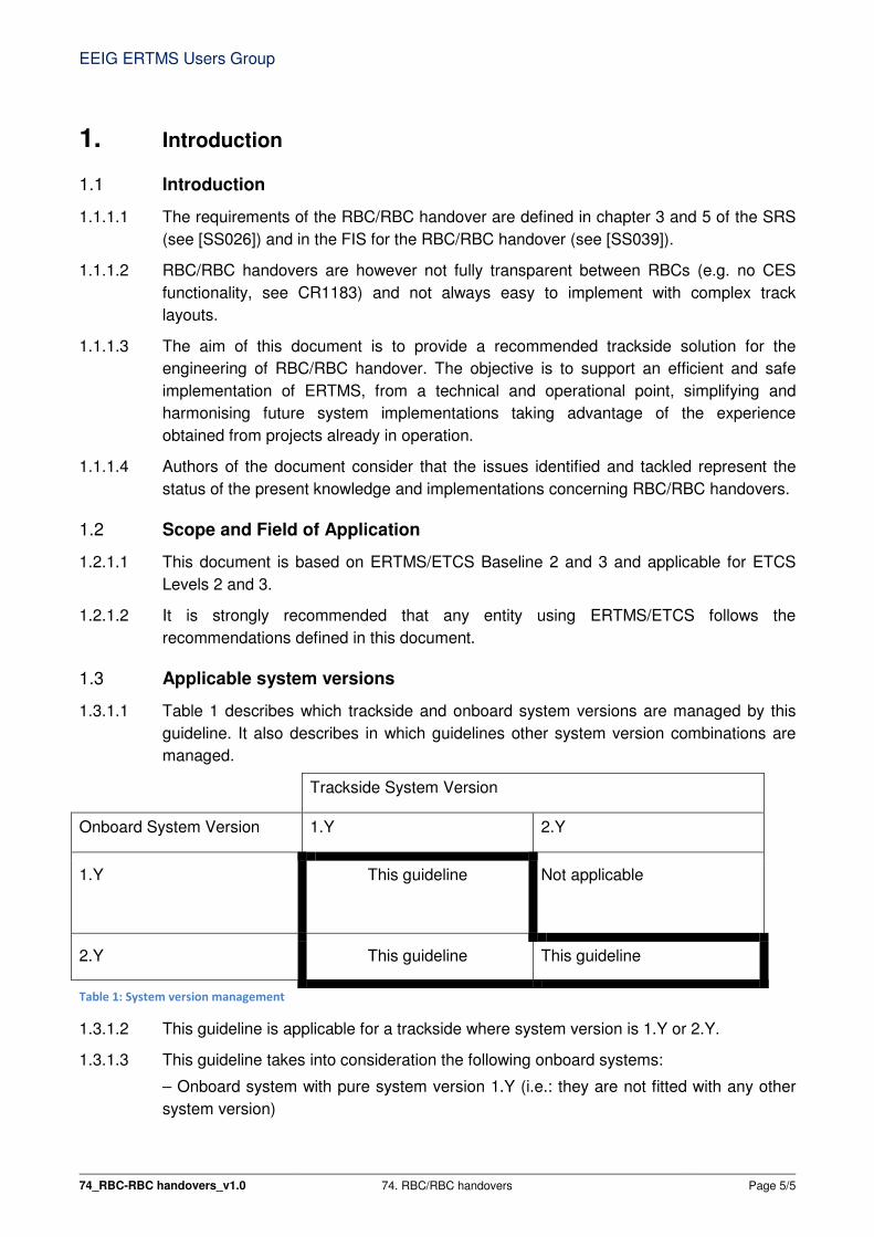
1.3.1.1 Table 1 describes which trackside and onboard system versions are managed by this
guideline. It also describes in which guidelines other system version combinations are
managed.
Trackside System Version
Onboard System Version 1.Y 2.Y
1.Y This guideline Not applicable
2.Y This guideline This guideline
Table 1: System version management
1.3.1.2 This guideline is applicable for a trackside where system version is 1.Y or 2.Y.
1.3.1.3 This guideline takes into consideration the following onboard systems:
– Onboard system with pure system version 1.Y (i.e.: they are not fitted with any other
system version)
EEIG ERTMS Users Group
74_RBC-RBC handovers_v1.0 74. RBC/RBC handovers Page 6/6
– Onboard system supporting version 1.Y and 2.Y, with active system version 1.Y or 2.Y
1.3.1.4 An RBC/RBC handover between a Baseline 3 RBC and a Baseline 2 RBC requires
specific attention. Requirements will be described in [SS129] which is under
development.
1.3.1.5 Note: Connections between Baseline 3 RBCs with at least one RBC that is operating
with system version X=1 is covered by [SS039 3.1.0/3.2.0] chapter 6.
1.3.2 Definitions
1.3.2.1 Intentionally left empty.
1.4 Document structure
1.4.1.1 Chapter 1 introduces the document and defines the scope.
1.4.1.2 Chapter 2 provides references, terms and abbreviations used in this document.
1.4.1.3 Chapter 3 provides the general functional steps for the RBC/RBC handover.
1.4.1.4 Chapter 4 provides a list of issues to be considered and for some issues a possible
solution.
1.4.1.5 Chapter 5 provides the recommendations for engineering RBC/RBC handovers.
EEIG ERTMS Users Group
74_RBC-RBC handovers_v1.0 74. RBC/RBC handovers Page 7/7
2. References and Abbreviations
2.1 Abbreviations
Abbreviation Description
ACC RBC Accepting RBC
AR Announcement RBC transition
HOV RBC Handing Over RBC
IXL Interlocking
MT Mobile Terminal
NR Radio Network Registration
p Packet, e.g. p131 is ETCS packet 131
RRI Route Related Information
RTO RBC transition order
2.2 References
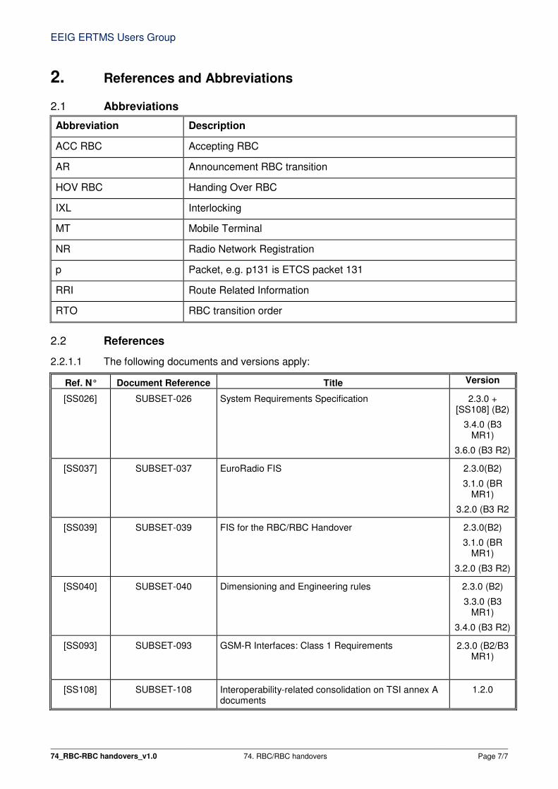
2.2.1.1 The following documents and versions apply:
Ref. N° Document Reference Title Version
[SS026] SUBSET-026 System Requirements Specification 2.3.0 + [SS108] (B2)
3.4.0 (B3 MR1)
3.6.0 (B3 R2)
[SS037] SUBSET-037 EuroRadio FIS 2.3.0(B2)
3.1.0 (BR MR1)
3.2.0 (B3 R2
[SS039] SUBSET-039 FIS for the RBC/RBC Handover 2.3.0(B2)
3.1.0 (BR MR1)
3.2.0 (B3 R2)
[SS040] SUBSET-040 Dimensioning and Engineering rules 2.3.0 (B2)
3.3.0 (B3 MR1)
3.4.0 (B3 R2)
[SS093] SUBSET-093 GSM-R Interfaces: Class 1 Requirements 2.3.0 (B2/B3 MR1)
[SS108] SUBSET-108 Interoperability-related consolidation on TSI annex A documents
1.2.0

EEIG ERTMS Users Group
74_RBC-RBC handovers_v1.0 74. RBC/RBC handovers Page 8/8
Ref. N° Document Reference Title Version
[SS113] SUBSET-113 Report from UNISIG Hazard Log 1.2.29
Under development
[SS129] SUBSET-129 FIS for the RBC/RBC Handover involving a Baseline 2
RBC Under
development
[ATAF] EUG_69 Automatic Track Ahead Free (B3) Guideline 1.5
[CRxxxx] ERA CR Database ERA CR Database -
EEIG ERTMS Users Group
74_RBC-RBC handovers_v1.0 74. RBC/RBC handovers Page 9/9
3. RBC/RBC Handover
3.1 Introduction
3.1.1.1 This chapter intends to give a general overview of how to perform an RBC transition
from the HOV RBC to the ACC RBC and can be used as a reference for the issues
discussed in chapter 4. The track layout and sequence diagram presented here are
further detailed in chapter 5.
3.1.1.2 The actual RBC/RBC handover procedures can be found in [SS026] 5.15 with more
detailed information.
3.2 Functional steps
3.2.1.1 In order to facilitate the recommendations detailed in chapter 5, the RBC transition is
divided into the following functional steps:
1) Radio Network registration (if required)
2) RBC transition announcement
3) RBC transition
3.2.1.2 The successful transition from HOV RBC to ACC RBC requires that each of these steps
is completed before the next is performed.
3.2.1.3 The Radio Network registration is only required if the two RBC areas use a different
radio network.
3.3 General track layout
3.3.1.1 The following drawing shows the general and relevant track design and balise groups
needed to perform the different functional steps of the RBC transition listed in paragraph
3.2.1.1. There are intentionally no signals shown in the figure as they are not relevant for
the transition procedure as such from a technical point of view.

EEIG ERTMS Users Group
74_RBC-RBC handovers_v1.0 74. RBC/RBC handovers Page 10/10
Figure 1: Generic track layout for RBC transition
3.3.1.2 The table below represents the balise groups and information (in ETCS packets) needed
for each functional step to succeed with an RBC transition.
BG BG DESCRIPTION BG INFORMATION (ETCS PACKETS)
NR Radio Network Registration Packet 45: Radio Network Registration
with the identity of the GSM-R network of the ACC
RBC area
AR Announcement RBC
transition
Packet 131: RBC transition order announcing the
coming RBC transition at the RBC/RBC border
RTO RBC transition order Packet 131: RBC transition order with immediate
order
Packet 45: Radio Network Registration
with the identity of the GSM-R network of the ACC
RBC area (optional)
Table 2: Balise groups for RBC transition
3.3.1.3 The information in the balise groups in the figures is only valid in the indicated train
running direction, unless defined otherwise.
3.3.1.4 Balise group NR orders the train to register with the appropriate radio network. This
means that the network must be available at this location. Network Registration
information is necessary in case the radio network changes at the RBC/RBC border.
This Balise group NR is optional required as this information could also be sent by the
HOV RBC.
EEIG ERTMS Users Group
74_RBC-RBC handovers_v1.0 74. RBC/RBC handovers Page 11/11
3.3.1.5 Balise group AR orders the train to establish communication session with the ACC RBC.
The actual moment to establish communication session is dependent on the number of
communication sessions the onboard is capable to use. This Balise group AR is optional
as the announcement could also be sent by the HOV RBC.
3.3.1.6 Balise group RTO is located at the RBC/RBC border and orders the immediate RBC
transition to the ACC RBC. This is required by [SS026] 5.15.1.3. This balise group will
also be needed for degraded situations in case no RBC/RBC handover was announced
and in case a not connected train will pass the border. The actual moment of
transferring the train supervision is dependent on the number of communication
sessions the onboard is capable to use.
3.3.1.7 In case the radio network changes at the RBC/RBC border and no balise group NR is
used the balise group RTO should contain an order to register with the appropriate radio
network for not connected trains, e.g. sleeping units.
3.4 General Sequence Diagram
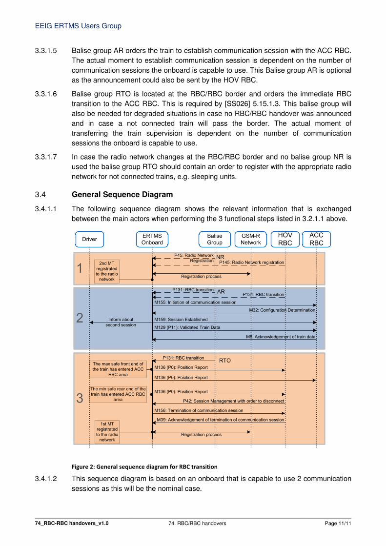
3.4.1.1 The following sequence diagram shows the relevant information that is exchanged
between the main actors when performing the 3 functional steps listed in 3.2.1.1 above.
3
DriverERTMS
Onboard
GSM-R
Network
P131: RBC transitionRTO
Balise
Group
ACC
RBC
The max safe front end of
the train has entered ACC
RBC area
1
2
P45: Radio Network
RegistrationNR
Registration process
2nd MT
registrated
to the radio
network
P131: RBC transitionAR
M155: Initiation of communication session
M159: Session Established
M32: Configuration Determination
M129 (P11): Validated Train Data
M8: Acknowledgement of train data
M136 (P0): Position Report
HOV
RBC
P131: RBC transition
M136 (P0): Position Report
Inform about
second session
The min safe rear end of the
train has entered ACC RBC
area
M136 (P0): Position Report
1st MT
registrated
to the radio
network
P42: Session Management with order to disconnect
M156: Termination of communication session
M39: Acknowledgement of termination of communication session
Registration process
P145: Radio Network registration
Figure 2: General sequence diagram for RBC transition
3.4.1.2 This sequence diagram is based on an onboard that is capable to use 2 communication
sessions as this will be the nominal case.

EEIG ERTMS Users Group
74_RBC-RBC handovers_v1.0 74. RBC/RBC handovers Page 12/12
3.4.1.3 In case of an onboard that is only capable to use 1 communication session the active
Mobile Terminal will not register to the other radio network in step 1, but will postpone
this registration till the connection is terminated with the HOV RBC in step 3. In step 2
there will be no session establishment with the ACC RBC, this session establishment
will be postponed till the connection is terminated with the HOV RBC in step 3 and after
any required radio network registration.
3.4.1.4 The information exchanged and the time required for that are further detailed for each
functional step in chapter 5. The dashed arrows in step 1 define the Radio Network
Registration by either balise group or HOV RBC. The dashed arrows in step 2 define the
RBC transition order by either balise group or HOV RBC.
3.4.1.5 The diagram above does not represent all the mandatory information exchanged by the
relevant actors but defines in general the different functional steps that are considered in
this document for the recommendations given in chapter 5.
3.4.1.6 The generation of movement authorities is not described in the general sequence
diagram. When the HOV RBC generates a movement authority which reaches the
RBC/RBC border, it informs the ACC RBC. This will nominally be before functional step
2.
3.4.1.7 The "first" Mobile Terminal (1st MT) refers to the one used for communication session
with HOV RBC and "second" Mobile Terminal (2nd MT) to the one used for
communication session with ACC RBC.
EEIG ERTMS Users Group
74_RBC-RBC handovers_v1.0 74. RBC/RBC handovers Page 13/13
4. Issues to be addressed
4.1 Introduction
4.1.1.1 This chapter lists issues that need to be considered for the engineering of RBC/RBC
handovers and most of them are further detailed in the recommended solutions given in
chapter 5. The issues that are not part of the recommended solutions are mentioned
here because projects may still need to consider them. For some of those issues a
possible solution is described.
4.2 Issues RBC/RBC handovers
4.2.1 RBC/RBC border mapping
4.2.1.1 The number of RBCs and the RBC/RBC border locations should be carefully
considered.
4.2.1.2 The following items are to be considered:
• Number of RBCs
• Area size per RBC
• RBC connection with interlockings (e.g. 1-to-n, n-to-1, n-to-n)
• Type of location of RBC/RBC borders (e.g. open line or stations area)
• Use of RBC telephone numbers (e.g. unique telephone number or a smart
routing to the specific RBC's based on RBC Identity)
• Other borders that need to coincide with an RBC/RBC border (e.g. change of
NID_C, national values, GSM-R/GPRS)
4.2.1.3 There is also no formal definition as to what constitutes an RBC and what constitutes an
IXL, so the border is often blurred, in particular when it comes to where specific controls
are implemented, at RBC or IXL level. This makes it difficult to determine an optimum
RBC/RBC border location where different suppliers, interlockings and RBCs are
involved.
4.2.1.4 This issue is further elaborated in the recommended solution.
4.2.2 Defining RBC/RBC border location
4.2.2.1 The following items are to be considered in relation to RBC/RBC border locations:
• Location of IXL borders i.e. should IXL and RBC/RBC borders be at the same or
different locations?
• Location of GSM-R cell borders due to potential communications issues.
• Location of GSM-R network borders due to potential communications issues.
• Location of traction changeover areas, due to the higher risk of stranding in an
area where no traction can be given. This is particularly relevant when an
RBC/RBC Handover is performed with 1 Mobile Terminal where communications
could be disturbed for too long and train could be braked.
• Location of track side objects, e.g. points covering border. This may introduce
additional complexity to the handover design and may impact on the ERTMS
EEIG ERTMS Users Group
74_RBC-RBC handovers_v1.0 74. RBC/RBC handovers Page 14/14
functions employed for emergency situations, for example the use of Conditional
Emergency Stop for flank protection at point areas.
4.2.2.2 When defining an RBC/RBC border location also the following items are to be
considered:
• Location when connection with the ACC RBC is initiated.
• Train traffic density and the required performance of the system and the interface
between the RBCs.
• Roll-out steps of the ERTMS implementation, to avoid software/configuration
updates.
4.2.2.3 This issue is further elaborated in the recommended solution.
4.2.3 Operational processes
4.2.3.1 The following items related to operational processes are to be considered in relation to
RBC/RBC border locations:
• Data entry of RBC data at Start of Mission. It is possibly unclear for the driver
which data to enter (see section 4.3.13).
• Start of Mission close to the RBC/RBC border when first MA is the one over
RBC/RBC border (including ATAF – see [ATAF]).
• Turn back movements (possibly connected with wrong RBC).
• For system version X=1, RBC/RBC handover borders shall not be located where
SH or RV mode movements could take place as RBC/RBC handovers are
rejected by the onboard (See [SS040] 6.1.1.1.1).
• For system version X=2 the need for RV movements across the RBC/RBC
border should be avoided as the RBC transition orders are not accepted in RV
mode. If RV moves are required, the operational consequences need to be
managed.
• It may not be possible to conduct the normal start of mission procedure within
the 1st block before the border if utilising ATAF with CES (See [ATAF]) as a
triggered CES in the ACC RBC area cannot be sent to the HOV RBC by which a
train still could be supervised, e,g. during a single session handover(see section
4.2.7 and 4.3.2)
• No 2nd RBC/RBC handover within (T_NVCONTACT * maximum driving speed +
train length + distance required for an MA ahead to avoid the driver starting to
brake) due to the MA extension arriving late as there is insufficient time to
connect with 2nd ACC RBC. The driver may start to brake due to the
presentation/interpretation of TTI or Target Distance information, or the indication
point on the planning area on Baseline 3 Release 2 onboard, or pre-indication on
other onboards.
• The minimum MA length should preferably be (T_NVCONTACT * maximum
driving speed + distance required for an MA ahead to avoid the driver starting to
brake) in advance of the RBC/RBC border to avoid lack of MA in case an
RBC/RBC handover will take place with an onboard handling only one
EEIG ERTMS Users Group
74_RBC-RBC handovers_v1.0 74. RBC/RBC handovers Page 15/15
communication session. The driver may start to brake due to the
presentation/interpretation of TTI or Target Distance information, or the indication
point on the planning area on Baseline 3 Release 2 onboards, or pre-indication
on other onboards.
4.2.3.2 This issue is further elaborated in the recommended solution.
4.2.4 Performance
4.2.4.1 The size of an RBC area and the amount of borders could be based on the RBC
performance. The following items related to RBC performance are to be considered:
• Restrictions on the number of trains that an RBC can simultaneously manage
(e.g. is there an upper limit driven by processing time, communications channels
etc.).
• Availability issues when using large control areas (if small number of RBC’s).
• Maintainability issues when using large control areas (if small number of RBC’s).
• System down time for configuration updates, impact on ongoing train traffic.
• Hot swappable, hot configurable, short down time.
• Complexity of the track layout (number of objects managed by the RBC/IXL)
4.2.4.2 This issue is not elaborated in the recommended solution.
4.2.5 Location of NID_C change in relation to RBC/RBC border
4.2.5.1 Some RBCs can handle only one set of national values and only one NID_C
identification to which the set of national values applies. This potential limitation needs to
be taken into account at RBC/RBC handover in terms of the national values.
4.2.5.2 Some mitigations are described in chapter 5.
4.2.6 Supervision gap in RBC/RBC handover
4.2.6.1 The switch of RBC supervision in the onboard at the RBC/RBC handover is performed
when the onboard reports the position passing the RBC/RBC borderwith the max safe
front end ([SS026], 5.15.2.2.4.1 and 5.15.2.2.5.1).
4.2.6.2 If the confidence interval is large, and the train is stopped before it is actually at the
RBC/RBC border (for example due to a service brake reaction on expiration of
T_NVCONTACT) and the max safe front end has already passed the border, then the
handover to the ACC RBC is performed, but the train is in contact with the ACC RBC
that actually cannot authorize any movements before the actual border as it has no
authority over the RBC area that the train is actually in.
4.2.6.3 This issue may also arise if a train stops at a normal stopping position in close proximity
to the border and the max safe front end has already passed the border and the
handover to the accepting RBC is performed. If the train subsequently performs an End
of Mission followed by a new Start of Mission the last known RBC is the ACC RBC
which again cannot authorize any train movements as it has no authority over the RBC
area that the train is actually in.
4.2.6.4 For this risk hazard ETCS-H0022 was raised in [SS113].
EEIG ERTMS Users Group
74_RBC-RBC handovers_v1.0 74. RBC/RBC handovers Page 16/16
4.2.6.5 Note: CR1228 was raised to propose a solution to this issue, but this has not been
incorporated into the relevant specifications as part of release 2 for baseline 3, and as of
the date of issue of this guideline document there is no agreed solution.
4.2.6.6 Some mitigations are described in chapter 5.
4.2.7 Onboards handling only one communications session
4.2.7.1 In clause [SS026] 3.15.1.1.3 it is described that performing an RBC/RBC handover with
an onboard which can only handle one communication session may result in
performance penalties since it will not be able to “prepare” the expected supervision.
4.2.7.2 This could also lead to safety issues as when switching from RBCs there is, for some
time and distance, no supervision available from any RBC. Any safety or performance
related controls dependent on information being transmitted between the RBC and the
train in the period during which the supervision is not available will be ineffective, for
example co-operative shortening movement authority, conditional or unconditional
emergency stop, or position report etc. Resulting hazards and their mitigation must form
part of the implementation design.
4.2.7.3 The consequences of lack of supervision could be compared to normal loss of radio
communication inside an RBC area. The difference in this case is that all trains with one
communication session available will suffer this at the same location and basic
mitigations could not be sufficient enough in case of frequent occurrence of these trains.
4.2.7.4 In [SS026 3.6.0] an RBC/RBC handover with an onboard which can only handle one
communication session is seen as degraded situation (see also section 5.4).
4.2.7.5 Some mitigations are described in chapter 5.
4.2.8 Radio network identity and RBC contact details
4.2.8.1 Radio data information (Radio network identity and RBC contact details i.e. RBC identity
and telephone number) and changes to this information are managed by the onboard
based on packets received from the trackside or via driver entered or revalidated data,
and according to the mode of operation.
4.2.8.2 Transitions to No Power (NP) mode do not affect radio network identity, but cause the
RBC contact details to be set to invalid. These contact details will need to be revalidated
at Start of Mission in the following circumstances:
• Without cold movement detector any transition to NP will require revalidation of
RBC contact details.
• With cold movement detector revalidation is only required if movement is
detected.
4.2.8.3 Where trains are hauled in NP mode over a border and re-awakened in a different
location, the Radio Network identity and/or RBC contact details stored by the onboard
may not be suitable for the awakening location and the driver may be required to enter
the correct contact details during start of mission. Also, following train maintenance
where onboard components have been changed out, the data communication
information may be unknown or incorrect for the maintenance location.
EEIG ERTMS Users Group
74_RBC-RBC handovers_v1.0 74. RBC/RBC handovers Page 17/17
4.2.8.4 Note: The available National Values in the onboard could also not be suitable for the
awakening location.
4.2.8.5 Some mitigations are described in chapter 5.
4.2.9 Train data changed during RBC/RBC handover
4.2.9.1 In the [SS039 2.3.0] there is only one possibility to send train data; namely in the pre-
Announcement message. That means that in case train data has changed (e.g. due to
input from external sources) during an ongoing handover transaction, it is not clear how
to inform the Accepting RBC about this new train data without cancelling the handover
process.
4.2.9.2 For this risk hazard ETCS-H0037 was raised in [SS113]. This risk is applicable if one or
both RBCs involved in the RBC/RBC handover are based on ERTMS/ETCS Baseline 2.
Mitigation can be found in [SS113].
4.2.9.3 This issue is not elaborated in the recommended solution.
4.2.10 Faulty definition of Q_RRIMACHANGE and Q_TDCHANGE
4.2.10.1 The definition of the variables Q_RRIMACHANGE and Q_TDCHANGE is incorrect in
[SS039 2.3.0]. CR1088 was raised and has a solution for ERTMS/ETCS Baseline 3.
4.2.10.2 For this risk hazard ETCS-H0047 was raised in [SS113]. This risk is applicable if one or
both RBCs involved in the RBC/RBC handover are based on ERTMS/ETCS Baseline 2.
Mitigation can be found in [SS113].
4.2.10.3 This issue is not elaborated in the recommended solution.
4.2.11 Session establishment leads to supervision gap for vehicles with one mobile
during RBC/RBC handover
4.2.11.1 Some system aspects have been missed in [SS026 3.4.0] in relation to combination of
RBC/RBC transition order and session establishment order. This could lead to
supervision by the ACC RBC while still in HOV RBC area.
4.2.11.2 For this risk hazard ETCS-H0070 was raised in [SS113]. Mitigation can be found in
[SS113]. For ERTMS/ETCS Baseline 3 Release 2 onboards this is solved by CR933.
4.2.11.3 This issue is not elaborated in the recommended solution.
4.2.12 RBC/RBC transition not to be combined with session management
4.2.12.1 The onboard reaction to an RBC/RBC transition order received together with a session
management order is not unambiguously defined. CR933 is implemented in
ERTMS/ETCS Baseline 3 Release 2. A solution for other baselines could be to not
combine the RBC/RBC transition order (p131) with the session management order (p42)
in the same balise group, but in another balise group.
4.2.12.2 This issue is not elaborated in the recommended solution.
EEIG ERTMS Users Group
74_RBC-RBC handovers_v1.0 74. RBC/RBC handovers Page 18/18
4.2.13 Supervision change by position report
4.2.13.1 Due to issues reading balise groups the RBC/RBC transition could be reported by a
balise group in the RBC/RBC handover area instead of the balise group at the border. If
this balise group is not known the RBC supervision may not be changed from HOV RBC
to ACC RBC correctly.
4.2.13.2 The HOV RBC should also have knowledge about other BG after the RBC/RBC border.
4.2.13.3 This issue is not elaborated in the recommended solution.
4.2.14 TSRs in the RBC/RBC handover area
4.2.14.1 TSR information in the ACC RBC area can be transferred to the HOV RBC as part of
RRI information. However there is no specified facility for the transfer of TSR
information in the HOV RBC area to the ACC RBC. This means that for degraded
moves through the RBC/RBC handover area, TSRs in the HOV area can only be
included in a first MA from the ACC RBC if special arrangements are implemented to
define that TSR information in the ACC RBC
4.2.14.2 The ACC RBC could be configured with track description information covering maximum
train length prior to the RBC/RBC border to avoid the “Entering FS/OS” message being
displayed to a driver when the ACC RBC provides an MA following a degraded move
over the border. However where this information is configured in the ACC RBC, a lack
of information on TSRs in the HOV RBC area will not result in the “Entering FS/OS”
message because there is track description information for the entire length of the train
and the train cannot know that TSR information is potentially missing.
4.2.14.3 If the ACC RBC is not configured with track description information covering maximum
train length prior to the RBC/RBC border, the train in degraded situation passing the
RBC/RBC border will not receive any track description from the HOV RBC. This will
result in an “Entering FS/OS” message and the driver is responsible for any applicable
temporary speed restriction.
4.2.14.4 Some mitigations are described in chapter 5.
4.2.15 Trackside degraded situations
4.2.15.1 In case of minor trackside failures, e.g. failure of one balise group, the RBC/RBC
transition still should be performed. Redundancy concepts are to be considered for
balise failures and communication issues.
4.2.15.2 This issue is not elaborated in the recommended solution.
4.2.16 RBC/RBC Handover coincides with level transition Level 2 – Level 3
4.2.16.1 At the RBC/RBC Handover a level transition between Level 2 and Level 3 can coincide
as both Levels use RBC communication.
4.2.16.2 The location of the actual level transition is based on the estimated front end ([SS026]
5.10.1.5). The location of the actual RBC transition is based on the max safe front end
([SS026] 5.15.2.2.5).
EEIG ERTMS Users Group
74_RBC-RBC handovers_v1.0 74. RBC/RBC handovers Page 19/19
4.2.16.3 Based on this behaviour it is possible that an onboard reports the "wrong" level to the
supervising RBC until a new position report is provided with the estimated front end in
advance of the border.
4.2.16.4 This issue is not elaborated in the recommended solution.
4.3 Functional constraints RBC/RBC handover
4.3.1.1 Some functions are not available on the RBC/RBC handover interface and cannot be
used for trains passing the RBC/RBC border. In this paragraph those functions are
described.
4.3.1.2 It should be kept in mind that if only one session could be established the train will be
not connected and thus not supervised by ACC RBC for some distance in the ACC RBC
area. In general all functions based on radio messages are for this distance not
available.
4.3.1.3 The dynamic behaviour, e.g. train positioning based on dynamic confidence interval, and
timing constraints, e.g. time for session establishment and termination, are also to be
considered when designing an RBC/RBC transition. This is applicable for RBC/RBC
handovers with one and two sessions.
4.3.2 Conditional Emergency Stop function
4.3.2.1 The Conditional Emergency Message (M15) cannot be sent on the RBC/RBC interface,
nor is a specific RBC/RBC handover function available to fulfil this function. Note: For
this issue CR1193 was raised.
4.3.2.2 The Conditional Emergency Stop function could be used for depart authorisation based
on the guideline [ATAF].
4.3.2.3 The Conditional Emergency Stop function could be used as emergency stop under
certain hazardous situations, e.g. flank protection.
4.3.2.4 Some mitigations are described in chapter 5.
4.3.3 Revocation of emergency stop function
4.3.3.1 The Revocation of Emergency Stop Message (M18) cannot be sent by the ACC RBC
when a train received in rear of the RBC/RBC transition a Conditional Emergency Stop
Message (M15) or Unconditional Emergency Stop Message (M16) from the HOV RBC
and passed the RBC/RBC border before a Revocation of Emergency Stop Message
(M18) is sent.
4.3.3.2 This is because the Emergency message identity (NID_EM) is not known by the ACC
RBC.
4.3.3.3 A new movement authority will not be accepted until the emergency message has been
revoked, a possible procedure is to use the Override procedure to revoke the
emergency stop.
4.3.3.4 This issue is not elaborated in the recommended solution.

EEIG ERTMS Users Group
74_RBC-RBC handovers_v1.0 74. RBC/RBC handovers Page 20/20
4.3.4 Text message function
4.3.4.1 Text messages (p72, 76) cannot be sent on the RBC/RBC interface nor is a specific
RBC/RBC handover function available to fulfil this function.
4.3.4.2 If text messages are required while the ACC RBC is not yet supervising, a possible
solution is that the information could be sent by balises provided that the information is
static.
4.3.4.3 This issue is not elaborated in the recommended solution.
4.3.5 Movement authority request and position report parameters
4.3.5.1 Movement authority request (p57) and position report parameters (p58) cannot be sent
on the RBC/RBC interface nor is a specific RBC/RBC handover function available to
fulfil this function.
4.3.5.2 Changes in these parameters cannot be received by the onboard as long as the ACC
RBC is not yet supervising. There is no specific solution available.
4.3.5.3 This issue is not elaborated in the recommended solution.
4.3.6 List of balises for SH area or and List of balises in SR authority
4.3.6.1 List of balises for SH area (p49) and List of balises in SR authority (p63) cannot be sent
on the RBC/RBC interface nor is a specific RBC/RBC handover function available to
fulfil this function.
4.3.6.2 If a List of balises for SH area (p49) is required while the ACC RBC is not yet
supervising, the information could be sent by balises provided that the information is
static.
4.3.6.3 List of balises in SR authority (p63) cannot be received by the onboard as long as the
ACC RBC is not yet supervising. The solution described in CR494 is to send the
information as soon as the ACC RBC is supervising neglecting the possible supervision
gap if only one session available. There is no specific solution available.
4.3.6.4 This issue is not elaborated in the recommended solution.
4.3.7 Data used by applications outside the ERTMS/ETCS system
4.3.7.1 Data used by applications outside the ERTMS/ETCS system (p44) cannot be sent on
the RBC/RBC interface nor is a specific RBC/RBC handover function available to fulfil
this function.
4.3.7.2 Changes in this data cannot be received or sent by the onboard as long as the ACC
RBC is not yet supervising. There is no specific solution available.
4.3.7.3 This issue is not elaborated in the recommended solution.
4.3.8 Geographical position function
4.3.8.1 Geographical position information (p79) cannot be sent on the RBC/RBC interface nor is
a specific RBC/RBC handover function available to fulfil this function.
EEIG ERTMS Users Group
74_RBC-RBC handovers_v1.0 74. RBC/RBC handovers Page 21/21
4.3.8.2 If geographical position information is required while the ACC RBC is not yet
supervising, a possible solution is that the information could be sent by balises provided
that the information is static.
4.3.8.3 This issue is not elaborated in the recommended solution.
4.3.9 Reversing function
4.3.9.1 Information about Reversing (p138, 139) cannot be sent on the RBC/RBC interface nor
is a specific RBC/RBC handover function available to fulfil this function.
4.3.9.2 Reversing information could be sent by balises, but this information is normally dynamic
and will require switchable balises. There is no specific solution available
4.3.9.3 This issue is not elaborated in the recommended solution.
4.3.10 Train running number from RBC
4.3.10.1 The Train running number from RBC (p140) cannot be sent on the RBC/RBC interface
nor is a specific RBC/RBC handover function available to fulfil this function. There is no
specific solution available.
4.3.10.2 This issue is not elaborated in the recommended solution.
4.3.11 Radio hole function
4.3.11.1 Radio hole function as track condition (p68) is specified for RBC/RBC handover.
However using the radio hole functionality in the RBC/RBC handover area could lead to
technical issues as radio communication is essential for the RBC/RBC handover.
4.3.11.2 For example the beginning of a real radio hole should only start in the ACC RBC area
after the handing over has taken place as the actual RBC/RBC handover based on p131
should be reported to the HOV RBC.
4.3.11.3 Therefore this function cannot be used in RBC/RBC handover areas. Where radio hole
functionality is used to manage GSM-R radio failures, for example base station failures,
this will not be available near RBC/RBC borders.
4.3.11.4 Some mitigations are described in chapter 5.
4.3.12 TSR revocation function
4.3.12.1 TSR Revocation function (p66) is not mandatory on the RBC/RBC interface for Baseline
2 according to [SS039 230] 5.3.1.2. It is possible that TSR Revocation information
cannot be passed from a handing-over RBC to the accepting RBC, or vice versa. This
means that a TSR Revocation in the RBC/RBC handover area that impacts on
operations (within train length of the RBC/RBC border) cannot be included in the MA
issued by the accepting RBC. This could result in the situation where the speed of a
train crossing the RBC/RBC border is not controlled correctly and this could lead to
performance issues.
4.3.12.2 This issue is not elaborated in the recommended solution.
EEIG ERTMS Users Group
74_RBC-RBC handovers_v1.0 74. RBC/RBC handovers Page 22/22
4.3.13 Message acknowledgement function
4.3.13.1 The acknowledgement message (M146) is not available on the RBC/RBC handover
interface. Functions that need an acknowledgement are not possible to use.
4.3.13.2 An example is the need of knowing if a train in the HOV RBC area has accepted a level
transition order to ensure the STM system is activated in hot standby in case the ACC
RBC area uses an overlay with LNTC.
4.3.13.3 This issue is not elaborated in the recommended solution.
4.3.14 RRI confirmation
4.3.14.1 RRI confirmation is not mandatory on the RBC/RBC interface for Baseline 2 according
to [SS039 v230] 5.3.1.2. It is possible that RRI confirmation information cannot be
passed from a handing-over RBC to the accepting RBC, or vice versa. This means
functions relying on the RRI confirmation cannot be used if one or both RBC’s are based
on ERTMS/ETCS Baseline 2. A function is for example request for shortening of MA.
4.3.14.2 This issue is not elaborated in the recommended solution.
4.3.15 Constraints for packets and messages
4.3.15.1 In [SS039 2.3.0] 6.3.1 and [SS039 3.1.0/3.2.0] 5.3.1 the following additional constraints
are described for packet and messages (see [SS039] for more details):
• Q_TRACKINIT = 1 shall not be sent
• Number of TSR shall not exceed limit set by N_REMAINTSR
• LX identities are not duplicated
• Track description may also be changed if Q_RRIMACHANGE <>0
• Special value “Now” in the national values (p3) and level transition order (p41)
shall not be used
• The status of Q_TDCHANGE shall be maintained until an RRI message
indicating this changed track data has been acknowledged by the HOV RBC.
4.3.15.2 In the messages on the RBC/RBC interface only the following modes (M_MODE) can be
sent because in other modes either the Accepting RBC cannot forward any information
to the on-board or the on-board cannot handle an RBC/RBC handover: FS, OS, SR, TR,
PT, NL or LS(SV2.Y).
4.3.15.3 This issue is not elaborated in the recommended solution.
4.3.16 Unnecessary functions
4.3.16.1 Some packets and messages are not available on the RBC/RBC interface which will
normally not be used at RBC/RBC handovers. For completeness these are described
here together with the rationale.
4.3.16.2 Movement Authority with shifted reference (M33): as information from the ACC RBC
area is always in advance of the current train location this function is not required.

EEIG ERTMS Users Group
74_RBC-RBC handovers_v1.0 74. RBC/RBC handovers Page 23/23
4.3.16.3 Session Management (p42): a session management order will intervene with the
session management for the RBC/RBC handover and this function is thus not
necessary. For overlay situations Session Management can be sent by balises.
4.3.16.4 Radio Network registration (p45): a radio network change should be performed before
session establishment with the ACC RBC and this function is thus not necessary.
4.3.16.5 RBC/RBC transition order (p131): as only one RBC/RBC handover can be handled at a
time, it is not possible to announce a second RBC/RBC handover. This should be taken
into account when engineering consecutive RBC/RBC handovers.
4.3.16.6 Train to track messages (p0, 1, 3, 4, 9): this information is normally sent directly to the
ACC RBC. If only one session is available this information cannot be sent as long as the
ACC RBC is not supervising.
4.3.16.7 This issue is not elaborated in the recommended solution.

EEIG ERTMS Users Group
74_RBC-RBC handovers_v1.0 74. RBC/RBC handovers Page 24/24
5. Recommended solution RBC/RBC handover
5.1 Basic considerations
5.1.1.1 Ideally there should not be RBC/RBC handovers for a train. System limitations will lead
however to the need for more than one physical RBC. The number of RBCs should be
limited as far as is practicable.
5.1.1.2 There are system developments to make it possible to perform an RBC/RBC handover
without interfering with the communication with the train, i.e. changing from one physical
RBC to another without the need for a RBC/RBC handover based on the ERTMS
specification and without the need for connecting and disconnecting the radio
communication on ERTMS application level. This could make an efficient and safe
implementation possible. The recommended solution is based on the situation such a
solution is not available or not possible, e.g. at geographical borders.
5.1.1.3 It is recommended that both parties of each RBC check all applicable operational
scenarios at the RBC/RBC handover location, e.g. Start of Mission, route revocation and
turn back movements, in relation with their specific RBC behaviour.
5.1.1.4 It is recommended that both parties agree on the use of non-mandatory functions.
5.1.1.5 The expected benefit of the described solution is:
• an efficient and safe implementation of RBC/RBC handover
5.1.1.6 The following issues from chapter 4 must be considered in the solution:
• RBC/RBC border mapping
• Defining RBC/RBC border location
• Operational processes
• Radio network identity and RBC contact details
• TSRs in the RBC/RBC handover area
• Conditional Emergency Stop function
• Radio hole function
5.2 Recommended solution
5.2.1 General solution
5.2.1.1 To overcome most issues RBC/RBC borders should be situated:
• On plain line i.e. where there are no or limited infrastructure features (junctions,
level crossings etc.) that the RBC/RBC handover would need to take into account.
• Avoiding GSM-R cell borders as mixing RBC/RBC borders and GSM-R cell
borders can impact on performance.
5.2.1.2 The distance D1 (see Figure 1) between an RBC/RBC border and the items as
described in 4.2.2.1 should be based on driving time at line speed. The driving time
should be based on the time to set up the communication session with the new RBC
(~40s - see [SS037], 7.3.2.3.1) and (where necessary) the time to register to the ‘new’
network (40s – see [SS093], 6.3.7.3).
EEIG ERTMS Users Group
74_RBC-RBC handovers_v1.0 74. RBC/RBC handovers Page 25/25
5.2.1.3 Within this distance D1 a normal start of mission scenario should be prevented as there
could be not enough time to connect to the ACC RBC. The minimum time to depart and
pass the RBC/RBC handover could be taken in to account.
5.2.1.4 Where an RBC/RBC border coincides with a (national) border, the RBC owners shall
agree on the interface to avoid issues related to messages not described in the RBC
interface which could be sent by the RBC, or optional functions that may or may not
have been implemented.
5.2.1.5 If NID_C and/or National Values have to be changed at the RBC/RBC border the RBCs
should be capable of handling multiple NID_C and National Values sets.
5.3 Specific recommendations
5.3.1 Solution for onboards with only one communication session
5.3.1.1 In general the impact on performance and safety when the RBC/RBC border is passed
with a train with one communication session available must be considered as part of the
implementation (see section 4.2.7).
5.3.1.2 Adding some distance to D1 (see section 5.2.1) could solve performance penalties and
safety issues. This additional distance should be based on the system behaviour that
the HOV RBC disconnects after the whole train has left the HOV RBC area and the time
to connect to the ACC RBC after disconnection.
5.3.1.3 For all safety mitigation used, e.g. CES for flank protection, it should be prevented that
trains with only one communication session have additional safety risks passing the
distance D1 while the onboard could be not supervised.
5.3.1.4 A possible solution is to limit the authorisation given by the ACC RBC through the
RBC/RBC interface by length and/or allowed speed until the onboard is connected to the
ACC RBC.
5.3.2 Solution for Supervision gap
5.3.2.1 To solve the supervision gap the RBC could be configured to announce the RBC/RBC
handover location beyond the actual RBC/RBC handover location and the RBC/RBC
handover is performed on the balise group at the RBC/RBC border.
5.3.2.2 The size of the odometer confidence interval could be managed through the provision of
additional balise groups on the approach to the RBC/RBC handover location.
5.3.2.3 If geographically possible, RBC/RBC handovers should be avoided where trains may
normally stop, although this does not address those occasions where the train may be
stopped abnormally e.g. in response to an expiry of T_NVCONTACT or on receipt of an
emergency stop command.
5.3.3 Solution for issues radio hole function
5.3.3.1 The issues of using the radio hole function during the RBC/RBC handover could be
solved by provision of better GSM-R network capability, for example additional
redundancy, in the RBC/RBC handover area (see section 4.3.11).
EEIG ERTMS Users Group
74_RBC-RBC handovers_v1.0 74. RBC/RBC handovers Page 26/26
5.3.4 Solution for NID_C change
5.3.4.1 When changing NID_C and/or national values at a border in relation with an RBC/RBC
handover it shall be checked that there are no undesired consequences when changing
the values; especially if the borders (NID_C, national values, RBC) are not at the same
location.
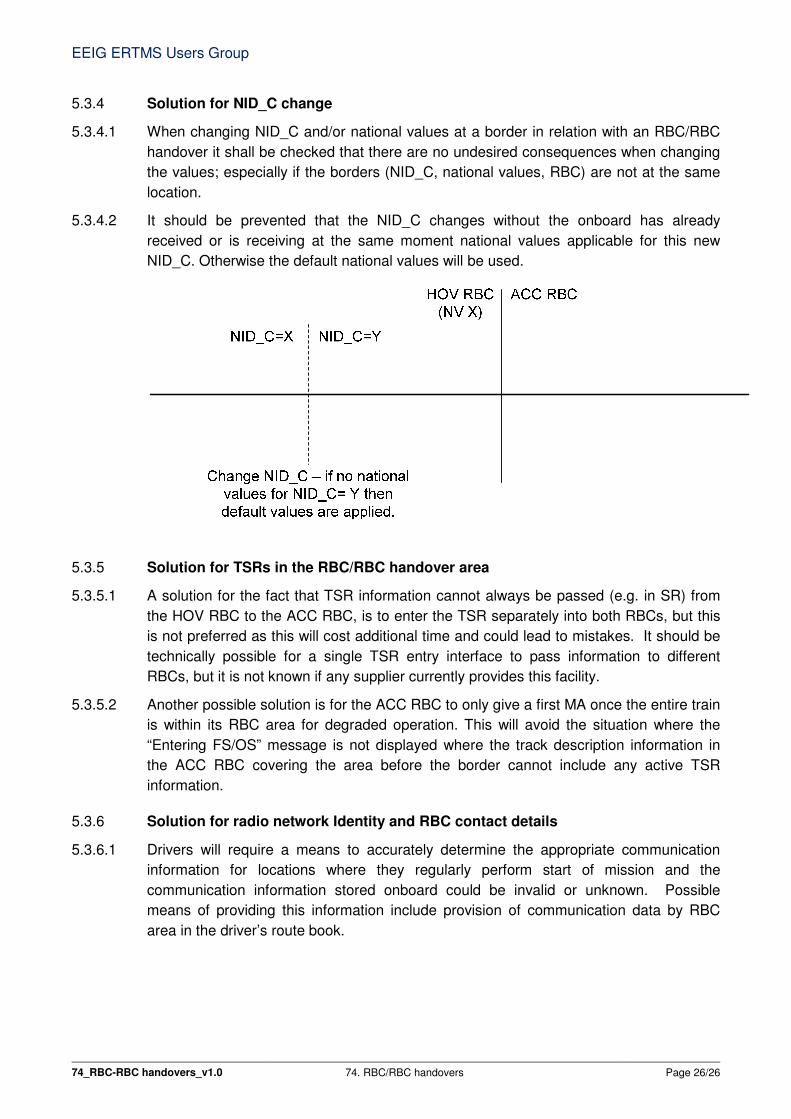
5.3.4.2 It should be prevented that the NID_C changes without the onboard has already
received or is receiving at the same moment national values applicable for this new
NID_C. Otherwise the default national values will be used.
5.3.5 Solution for TSRs in the RBC/RBC handover area
5.3.5.1 A solution for the fact that TSR information cannot always be passed (e.g. in SR) from
the HOV RBC to the ACC RBC, is to enter the TSR separately into both RBCs, but this
is not preferred as this will cost additional time and could lead to mistakes. It should be
technically possible for a single TSR entry interface to pass information to different
RBCs, but it is not known if any supplier currently provides this facility.
5.3.5.2 Another possible solution is for the ACC RBC to only give a first MA once the entire train
is within its RBC area for degraded operation. This will avoid the situation where the
“Entering FS/OS” message is not displayed where the track description information in
the ACC RBC covering the area before the border cannot include any active TSR
information.
5.3.6 Solution for radio network Identity and RBC contact details
5.3.6.1 Drivers will require a means to accurately determine the appropriate communication
information for locations where they regularly perform start of mission and the
communication information stored onboard could be invalid or unknown. Possible
means of providing this information include provision of communication data by RBC
area in the driver’s route book.

EEIG ERTMS Users Group
74_RBC-RBC handovers_v1.0 74. RBC/RBC handovers Page 27/27
5.4 Onboard recommendations
5.4.1.1 The onboard should be able to handle at least two communications sessions
simultaneously to facilitate communications setup with the handing over and accepting
RBC. This will prevent performance penalties and safety issues.
5.4.1.2 Baseline 3 Release 2 onboards are already required to handle at least two
communications sessions simultaneously, see [SS026 3.6.0] 3.5.2.4.
5.4.1.3 The optional onboard function Cold Movement Detector should be provided to minimize
RBC data entry on trains performing start of mission in the RBC/RBC handover area.