© siemens ag 2015 protection equipment 7 · 7/6 siemens ic 10 · 2015 protection equipment...
TRANSCRIPT

7
7
Siemens IC 10 · 2015
Price groups
PG 14O, 41B, 41E, 41F, 41G, 41H, 41J, 42F, 42J
7/2 Introduction
Motor starter protectors/circuit breakersSIRIUS 3RV2 motor starter protectors/circuit breakers up to 80 A
7/7 General data7/21 For motor protection 7/25 For motor protection with
overload relay function 7/26 For starter combinations 7/28 For transformer protection 7/29 For system protection according to
UL 489/CSA C22.2 No. 5 7/30 For transformer protection according to
UL 489/CSA C22.2 No.5 Accessories
7/31 - Mountable accessories7/34 - Busbar accessories7/37 - Rotary operating mechanisms7/38 - Mounting accessories7/43 - Enclosures and front plates7/46 3RV29 infeed system
SIRIUS 3RV1 motor starter protectors/circuit breakers up to 100 A
7/51 General data7/63 For motor protection7/64 For motor protection
with overload relay function7/65 For starter combinations7/66 For fuse monitoring7/67 For system protection according to
UL 489/CSA C22.2 No. 57/68 For distance protection
Accessories7/69 - Mountable accessories7/72 - Busbar accessories7/73 - Rotary operating mechanisms7/75 - Mounting accessories7/77 - Front plates
SIRIUS 3RV1 molded case motor starterprotectors up to 800 A
7/78 General data7/83 For motor protection7/84 For starter combinations
Accessories7/85 - Mountable accessories7/86 - Rotary operating mechanisms,
mounting accessories
Overload relays
7/87 General dataSIRIUS 3RU2 thermal overload relays
7/95 3RU2 up to 80 Afor standard applications
7/103 AccessoriesSIRIUS 3RU1thermal overload relays
7/106 3RU11 up to 100 A for standard applications
7/112 AccessoriesSIRIUS 3RB3 electronic overload relays
7/114 3RB30, 3RB31 up to 80 Afor standard applications
7/122 AccessoriesSIRIUS 3RB2electronic overload relays
7/124 3RB20, 3RB21 up to 630 Afor standard applications
7/133 Accessories for 3RB20, 3RB217/135 3RB22, 3RB23 up to 630 A
for High-Feature applications7/143 3RB24 for IO-Link, up to 630 A
for High-Feature applications7/150 Current measuring modules for
3RB22, 3RB23, 3RB24 7/153 Accessories for 3RB22, 3RB23, 3RB24
Notes:
The 3RV1, 3RU1 and 3RB2 devices (sizes S00/S0 to S12) can be found
- in the Catalog Add-On IC 10 AO · 2015 at the Information and Download Center
- in the interactive catalog CA 01 - in the Industry Mall
Conversion tool, e.g. from
- 3RV1 to 3RV2- 3RU11 to 3RU21- 3RB20/3RB21 to 3RB30/3RB31
see www.siemens.com/sirius/conversion-tool
Protection Equipment
© Siemens AG 2015
Click on the Article No. in the catalog PDF to access it in the Industry Mall and get all related information.
Or directly in the Internet, e. g. www.siemens.com/product?3RA1943-2C
3RA1943-2C3RA1943-2B3RA1953-2B3RA1953-2N
Article-No.

7/2 Siemens IC 10 · 2015
Protection EquipmentMotor Starter Protectors/Circuit Breakers
Introduction
7
■ Overview
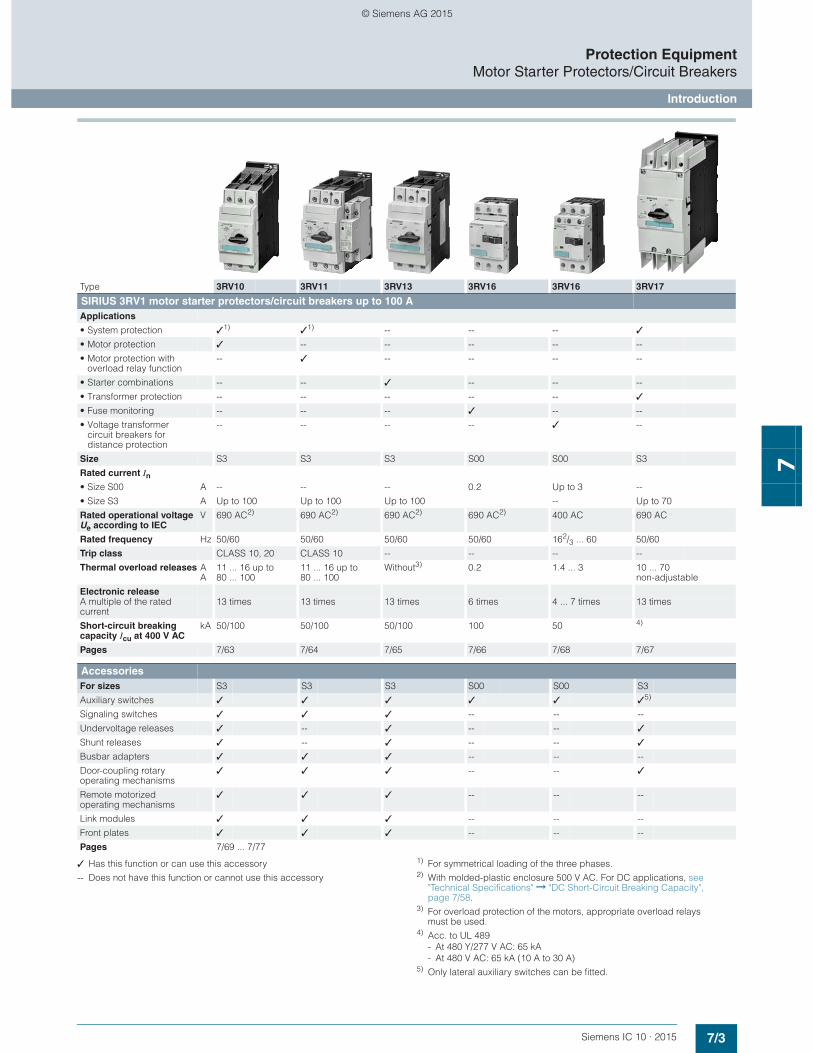
✓ Has this function or can use this accessory
-- Does not have this function or cannot use this accessory
1) For symmetrical loading of the three phases.2) With molded-plastic enclosure 500 V AC. For DC applications, see "Technical
Specifications" ➞ "DC Short-Circuit Breaking Capacity", page 7/16.
3) For overload protection of the motors, appropriate overload relays must be used.
4) According to UL 489 at 480 Y/277 V AC: 65 kA or 50 kA.5) Terminal covers are available for 3RV20 motor starter protectors with ring
terminal lug connection to ensure finger-safety.
Type 3RV20 3RV21 3RV23 3RV24 3RV27 3RV28
SIRIUS 3RV2 motor starter protectors/circuit breakers up to 80 A Applications
• System protection ✓1) ✓1) -- -- ✓ ✓
• Motor protection ✓ -- -- -- -- --
• Motor protection with overload relay function
-- ✓ -- -- -- --
• Starter combinations -- -- ✓ -- -- --
• Transformer protection -- -- -- ✓ ✓ ✓
Size S00, S0, S2 S00, S0, S2 S00, S0, S2 S00, S0, S2 S00, S0 S00, S0
Rated current In
• Size S00 A Up to 16 Up to 16 Up to 16 Up to 16 Up to 15 Up to 15• Size S0 A Up to 40 Up to 32 Up to 40 Up to 25 Up to 22 Up to 22• Size S2 A Up to 80 Up to 80 Up to 80 Up to 65 -- --
Rated operational voltage Ue according to IEC
V 690 AC2) 690 AC2) 690 AC2) 690 AC2) 690 AC 690 AC
Rated frequency Hz 50/60 50/60 50/60 50/60 50/60 50/60
Trip class CLASS 10 (S00 ... S2), CLASS 20 (S2)
CLASS 10 -- CLASS 10 -- --
Thermal overload releases AA
0.11 ... 0.16 up to 70 ... 80
0.11 ... 0.16 up to 70 ... 80
None3) 0.11 ... 0.16 up to 54 ... 65
0.16 ... 22Non-adjustable
0.16 ... 22Non-adjustable
Electronic release A multiple of the rated current 13 times 13 times 13 times 20 times 13 times 20 times
Short-circuit breaking capacity Icu at 400 V AC
kA 20/55/65/100 55/65/100 20/55/65/100 55/65/100 4) 4)
Pages 7/21 ... 7/23 7/25 7/26, 7/27 7/28 7/29 7/30
Accessories For sizes S00 S0 S2 S00 S0 S2 S00 S0 S2 S00 S0 S2 S00 S0 S00 S0
Auxiliary switches ✓ ✓ ✓ ✓ ✓ ✓ ✓ ✓ ✓ ✓ ✓ ✓ ✓ ✓ ✓ ✓
Signaling switches ✓ ✓ ✓ ✓ ✓ ✓ ✓ ✓ ✓ ✓ ✓ ✓ -- -- -- --
Undervoltage releases ✓ ✓ ✓ -- -- -- ✓ ✓ ✓ ✓ ✓ ✓ ✓ ✓ ✓ ✓
Shunt releases ✓ ✓ ✓ -- -- -- ✓ ✓ ✓ ✓ ✓ ✓ ✓ ✓ ✓ ✓
Isolator modules ✓ ✓ ✓ ✓ ✓ ✓ ✓ ✓ ✓ ✓ ✓ ✓ -- -- -- --
Insulated three-phase busbar system
✓ ✓ ✓ -- -- -- ✓ ✓ ✓ ✓ ✓ ✓ -- -- -- --
Busbar adapters ✓ ✓ ✓ ✓ ✓ ✓ ✓ ✓ ✓ ✓ ✓ ✓ -- -- -- --
Door-coupling rotary operating mechanisms
✓ ✓ ✓ ✓ ✓ ✓ ✓ ✓ ✓ ✓ ✓ ✓ ✓ ✓ ✓ ✓
Link modules ✓ ✓ ✓ ✓ ✓ ✓ ✓ ✓ ✓ ✓ ✓ ✓ -- -- -- --
Enclosures for surface mounting ✓ ✓ ✓ ✓ ✓ ✓ ✓ ✓ ✓ ✓ ✓ ✓ -- -- -- --
Enclosures for flush mounting ✓ ✓ -- ✓ ✓ -- ✓ ✓ -- ✓ ✓ -- -- -- -- --
Front plates ✓ ✓ ✓ ✓ ✓ ✓ ✓ ✓ ✓ ✓ ✓ ✓ -- -- -- --
Infeed system ✓ ✓ -- -- -- -- ✓ ✓ -- ✓ ✓ -- -- -- -- --
Terminal covers for ring terminal lug connections
✓5) ✓5) -- -- -- -- -- -- -- -- -- -- -- -- -- --
Sealable scale covers for setting knobs
✓ ✓ ✓ ✓ ✓ ✓ -- -- -- ✓ ✓ ✓ -- -- -- --
Pages 7/31 ... 7/50
© Siemens AG 2015
7/3Siemens IC 10 · 2015
Protection EquipmentMotor Starter Protectors/Circuit Breakers
Introduction
7
✓ Has this function or can use this accessory
-- Does not have this function or cannot use this accessory
1) For symmetrical loading of the three phases.2) With molded-plastic enclosure 500 V AC. For DC applications, see
"Technical Specifications" ➞ "DC Short-Circuit Breaking Capacity", page 7/58.
3) For overload protection of the motors, appropriate overload relays must be used.
4) Acc. to UL 489- At 480 Y/277 V AC: 65 kA- At 480 V AC: 65 kA (10 A to 30 A)
5) Only lateral auxiliary switches can be fitted.
Type 3RV10 3RV11 3RV13 3RV16 3RV16 3RV17
SIRIUS 3RV1 motor starter protectors/circuit breakers up to 100 A Applications
• System protection ✓1) ✓1) -- -- -- ✓
• Motor protection ✓ -- -- -- -- --
• Motor protection with overload relay function
-- ✓ -- -- -- --
• Starter combinations -- -- ✓ -- -- --
• Transformer protection -- -- -- -- -- ✓
• Fuse monitoring -- -- -- ✓ -- --
• Voltage transformer circuit breakers for distance protection
-- -- -- -- ✓ --
Size S3 S3 S3 S00 S00 S3
Rated current In
• Size S00 A -- -- -- 0.2 Up to 3 --
• Size S3 A Up to 100 Up to 100 Up to 100 -- Up to 70
Rated operational voltage Ue according to IEC
V 690 AC2) 690 AC2) 690 AC2) 690 AC2) 400 AC 690 AC
Rated frequency Hz 50/60 50/60 50/60 50/60 162/3 ... 60 50/60
Trip class CLASS 10, 20 CLASS 10 -- -- -- --
Thermal overload releases AA
11 ... 16 up to 80 ... 100
11 ... 16 up to 80 ... 100
Without3) 0.2 1.4 ... 3 10 ... 70non-adjustable
Electronic release A multiple of the rated current
13 times 13 times 13 times 6 times 4 ... 7 times 13 times
Short-circuit breaking capacity Icu at 400 V AC
kA 50/100 50/100 50/100 100 50 4)
Pages 7/63 7/64 7/65 7/66 7/68 7/67
Accessories For sizes S3 S3 S3 S00 S00 S3
Auxiliary switches ✓ ✓ ✓ ✓ ✓ ✓5)
Signaling switches ✓ ✓ ✓ -- -- --
Undervoltage releases ✓ -- ✓ -- -- ✓
Shunt releases ✓ -- ✓ -- -- ✓
Busbar adapters ✓ ✓ ✓ -- -- --
Door-coupling rotary operating mechanisms
✓ ✓ ✓ -- -- ✓
Remote motorized operating mechanisms
✓ ✓ ✓ -- -- --
Link modules ✓ ✓ ✓ -- -- --
Front plates ✓ ✓ ✓ -- -- --
Pages 7/69 ... 7/77
© Siemens AG 2015
7/4 Siemens IC 10 · 2015
Protection EquipmentMotor Starter Protectors/Circuit Breakers
Introduction
7
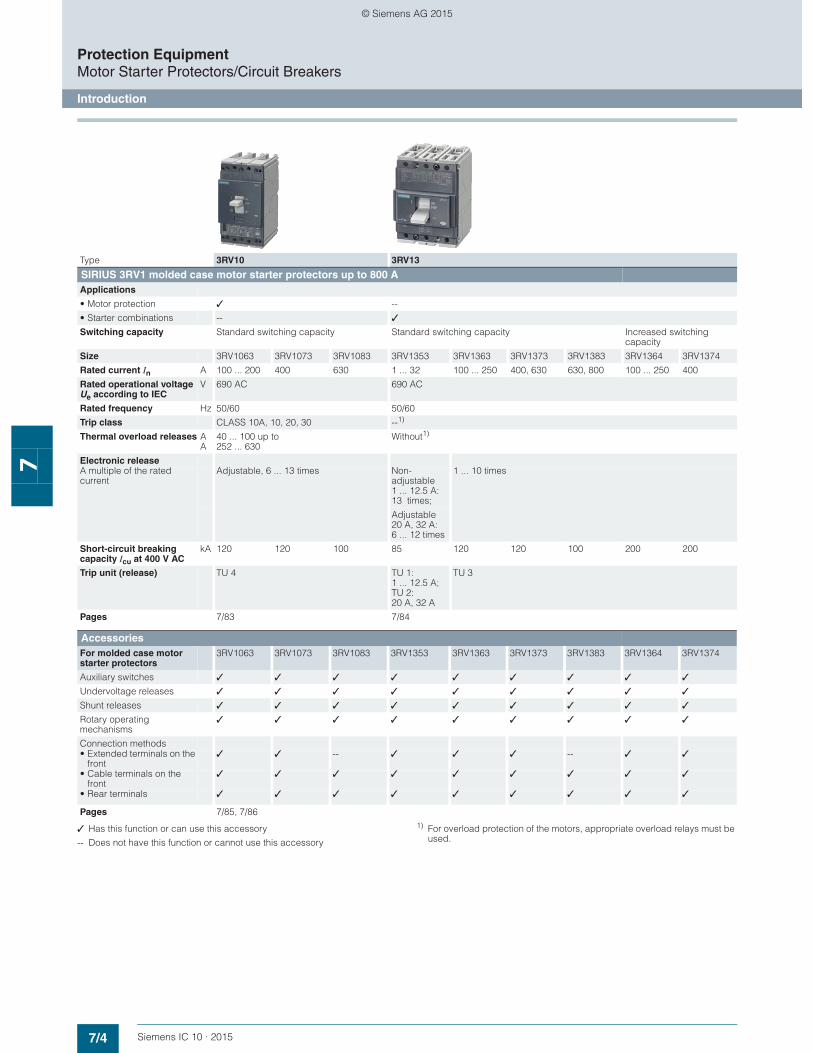
✓ Has this function or can use this accessory
-- Does not have this function or cannot use this accessory
1) For overload protection of the motors, appropriate overload relays must be used.
Type 3RV10 3RV13
SIRIUS 3RV1 molded case motor starter protectors up to 800 A Applications
• Motor protection ✓ --
• Starter combinations -- ✓
Switching capacity Standard switching capacity Standard switching capacity Increased switching capacity
Size 3RV1063 3RV1073 3RV1083 3RV1353 3RV1363 3RV1373 3RV1383 3RV1364 3RV1374
Rated current In A 100 ... 200 400 630 1 ... 32 100 ... 250 400, 630 630, 800 100 ... 250 400
Rated operational voltage Ue according to IEC
V 690 AC 690 AC
Rated frequency Hz 50/60 50/60
Trip class CLASS 10A, 10, 20, 30 --1)
Thermal overload releases AA
40 ... 100 up to 252 ... 630
Without1)
Electronic release A multiple of the rated current
Adjustable, 6 ... 13 times Non-adjustable 1 ... 12.5 A: 13 times;
1 ... 10 times
Adjustable 20 A, 32 A: 6 ... 12 times
Short-circuit breaking capacity Icu at 400 V AC
kA 120 120 100 85 120 120 100 200 200
Trip unit (release) TU 4 TU 1: 1 ... 12.5 A; TU 2: 20 A, 32 A
TU 3
Pages 7/83 7/84
AccessoriesFor molded case motor starter protectors
3RV1063 3RV1073 3RV1083 3RV1353 3RV1363 3RV1373 3RV1383 3RV1364 3RV1374
Auxiliary switches ✓ ✓ ✓ ✓ ✓ ✓ ✓ ✓ ✓
Undervoltage releases ✓ ✓ ✓ ✓ ✓ ✓ ✓ ✓ ✓
Shunt releases ✓ ✓ ✓ ✓ ✓ ✓ ✓ ✓ ✓
Rotary operating mechanisms
✓ ✓ ✓ ✓ ✓ ✓ ✓ ✓ ✓
Connection methods• Extended terminals on the
front✓ ✓ -- ✓ ✓ ✓ -- ✓ ✓
• Cable terminals on the front
✓ ✓ ✓ ✓ ✓ ✓ ✓ ✓ ✓
• Rear terminals ✓ ✓ ✓ ✓ ✓ ✓ ✓ ✓ ✓
Pages 7/85, 7/86
© Siemens AG 2015
7/5Siemens IC 10 · 2015
Protection EquipmentOverload Relays
Introduction
7
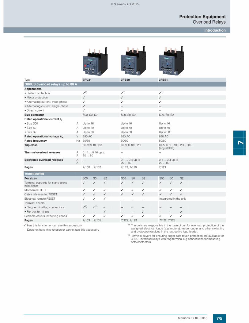
✓ Has this function or can use this accessory
-- Does not have this function or cannot use this accessory
1) The units are responsible in the main circuit for overload protection of the assigned electrical loads (e.g. motors), feeder cable, and other switching and protection devices in the respective load feeder.
2) Terminal covers for ensuring finger-safe touch protection are available for 3RU21 overload relays with ring terminal lug connections for mounting onto contactors.
Type 3RU21 3RB30 3RB31
SIRIUS overload relays up to 80 A Applications
• System protection ✓1) ✓1) ✓1)
• Motor protection ✓ ✓ ✓
• Alternating current, three-phase ✓ ✓ ✓
• Alternating current, single-phase ✓ -- --
• Direct current ✓ -- --
Size contactor S00, S0, S2 S00, S0, S2 S00, S0, S2
Rated operational current Ie• Size S00 A Up to 16 Up to 16 Up to 16
• Size S0 A Up to 40 Up to 40 Up to 40
• Size S2 A Up to 80 Up to 80 Up to 80
Rated operational voltage Ue V 690 AC 690 AC 690 AC
Rated frequency Hz 50/60 50/60 50/60
Trip class CLASS 10, 10A CLASS 10E, 20E CLASS 5E, 10E, 20E, 30E (adjustable)
Thermal overload releases AA
0.11 ... 0.16 up to 70 ... 80
-- --
Electronic overload releases AA
-- 0.1 ... 0.4 up to 20 ... 80
0.1 ... 0.4 up to 20 ... 80
Pages 7/100 ... 7/102 7/119, 7/120 7/121
AccessoriesFor sizes S00 S0 S2 S00 S0 S2 S00 S0 S2
Terminal supports for stand-alone installation
✓ ✓ ✓ ✓ ✓ ✓ ✓ ✓ ✓
Mechanical RESET ✓ ✓ ✓ ✓ ✓ ✓ ✓ ✓ ✓
Cable releases for RESET ✓ ✓ ✓ ✓ ✓ ✓ ✓ ✓ ✓
Electrical remote RESET ✓ ✓ ✓ -- -- -- Integrated in the unit
Terminal covers
• Ring terminal lug connections ✓2) ✓2) -- -- -- -- -- -- --
• For box terminals -- -- ✓ -- -- ✓ -- -- ✓
Sealable covers for setting knobs ✓ ✓ ✓ ✓ ✓ ✓ ✓ ✓ ✓
Pages 7/103 ... 7/105 7/122, 7/123 7/122, 7/123
© Siemens AG 2015

7/6 Siemens IC 10 · 2015
Protection EquipmentOverload Relays
Introduction
7
✓ Has this function or can use this accessory
-- Does not have this function or cannot use this accessory
1) The units are responsible in the main circuit for overload protection of the assigned electrical loads (e.g. motors), feeder cable, and other switching and protection devices in the respective load feeder.
2) With reference to the 3RB29.6 current measuring modules.3) Stand-alone installation without accessories is possible.
Type 3RU11 3RB20 3RB21 3RB22, 3RB23 3RB24
SIRIUS overload relays up to 630 A Applications
• System protection ✓1) ✓1) ✓1) ✓1)
• Motor protection ✓ ✓ ✓ ✓
• Alternating current, three-phase ✓ ✓ ✓ ✓
• Alternating current, single-phase ✓ -- -- ✓
• Direct current ✓ -- -- --
Size contactor S3 S3 ... S12 S3 ... S12 S00 ... S12
Rated operational current Ie• Sizes S00 and S0 A -- -- -- Up to 25 and 45 mm width
with current measuring modules 3RB2906-2BG1/3RB2906-2DG1
• Size S2 A -- -- -- Up to 100 and 55 mm widthwith current measuring module 3RB2906-2JG1
• Size S3 A Up to 100 Up to 100 Up to 100
• Size S6 A -- Up to 200 Up to 200 Up to 200 and 120 mm widthwith current measuring modules 3RB2956-2TH2/3RB2956-2TG2
• Size S10/S12 A -- Up to 630 Up to 630 Up to 630 and 145 mm widthwith current measuring module 3RB2966-2WH2
• Size 14 (3TF68/3TF69) A -- Up to 630 Up to 630 Up to 820 with current measuring module3RB2906-2BG1 and transformer 3UF1868-3GA00
Rated operational voltage Ue V 690/1 000 AC 690/1 000 AC 690/1 000 AC 690/1 000 AC2)
Rated frequency Hz 50/60 50/60 50/60 50/60
Trip class CLASS 10 CLASS 10, 20 CLASS 5, 10, 20, 30 Adjustable
CLASS 5, 10, 20, 30 Adjustable
Thermal overload releases A A
18 ... 25 up to 80 ... 100
-- -- --
Electronic overload releases A A
-- 12.5 ... 50 up to 160 ... 630
12.5 ... 50 up to 160 ... 630
0.3 ... 3 up to 63 ... 630
Pages 7/111 7/130, 7/131 7/132 7/141, 7/142, 7/152 7/149, 7/152
AccessoriesFor sizes S3 S3 S6 S10/S12 S3 S6 S10/S12 S00 S0 S2 S3 S6 S10/S12
Terminal supports for stand-alone installation
✓ 3) 3) 3) 3) 3) 3) 3) 3) 3) 3) 3) 3)
Mechanical RESET ✓ ✓ ✓ ✓ ✓ ✓ ✓ -- -- -- -- -- --
Cable releases for RESET ✓ ✓ ✓ ✓ ✓ ✓ ✓ -- -- -- -- -- --
Electrical remote RESET ✓ -- -- -- Integrated in the unit Integrated in the unit
Terminal covers ✓ ✓ ✓ ✓ ✓ ✓ ✓ -- -- -- ✓ ✓ ✓
Sealable covers for setting knobs Integrated in the unit ✓ ✓ ✓ ✓ ✓ ✓ ✓ ✓ ✓ ✓ ✓ ✓
Operator panel for 3RB24 evaluation module
-- -- -- -- -- -- -- ✓ ✓ ✓ ✓ ✓ ✓
Pages 7/112, 7/113 7/133, 7/134 7/133, 7/134 7/152 ... 7/154
© Siemens AG 2015
7/7Siemens IC 10 · 2015
Motor Starter Protectors/Circuit BreakersSIRIUS 3RV2 Motor Starter Protectors/Circuit Breakers up to 80 A
General data
7
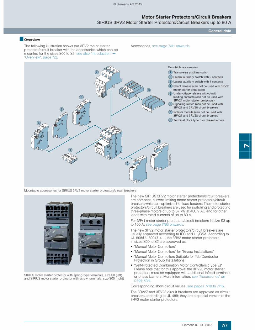
■ Overview
The following illustration shows our 3RV2 motor starter protector/circuit breaker with the accessories which can be mounted for the sizes S00 to S2, see also "Introduction" ➞ "Overview", page 7/2.
Accessories, see page 7/31 onwards.
Mountable accessories for SIRIUS 3RV2 motor starter protectors/circuit breakers
SIRIUS motor starter protector with spring-type terminals, size S0 (left)and SIRIUS motor starter protector with screw terminals, size S00 (right)
The new SIRIUS 3RV2 motor starter protectors/circuit breakers are compact, current limiting motor starter protectors/circuit breakers which are optimized for load feeders. The motor starter protectors/circuit breakers are used for switching and protecting three-phase motors of up to 37 kW at 400 V AC and for other loads with rated currents of up to 80 A.
For 3RV1 motor starter protectors/circuit breakers in size S3 up to 100 A, see page 7/63 onwards.
The new 3RV2 motor starter protectors/circuit breakers are usually approved according to IEC and UL/CSA. According to UL 508/UL 60947-4-1, the 3RV2 motor starter protectors in sizes S00 to S2 are approved as:• "Manual Motor Controllers"• "Manual Motor Controllers" for "Group Installations"• "Manual Motor Controllers Suitable for Tab Conductor
Protection in Group Installations"• "Self-Protected Combination Motor Controllers (Type E)"
Please note that for this approval the 3RV20 motor starter protectors must be equipped with additional infeed terminals or phase barriers. More information, see "Accessories" on page 7/38.
Corresponding short-circuit values, see pages 7/10 to 7/15.
The 3RV27 and 3RV28 circuit breakers are approved as circuit breakers according to UL 489; they are a special version of the 3RV2 motor starter protectors.
4
2
6
3
1
5
7
8
Transverse auxiliary switchLateral auxiliary switch with 2 contactsLateral auxiliary switch with 4 contactsShunt release (can not be used with 3RV21 motor starter protectors)
Signaling switch (can not be used with 3RV27 and 3RV28 circuit breakers)Isolator module (can not be used with 3RV27 and 3RV28 circuit breakers)Terminal block type E or phase barriers
Mountable accessories
Undervoltage release without/with leading contacts (can not be used with 3RV21 motor starter protectors)
1234
5
6
7
8
NS
B0_
0207
6a
© Siemens AG 2015
7/8 Siemens IC 10 · 2015
Motor Starter Protectors/Circuit BreakersSIRIUS 3RV2 Motor Starter Protectors/Circuit Breakers up to 80 A
General data
7
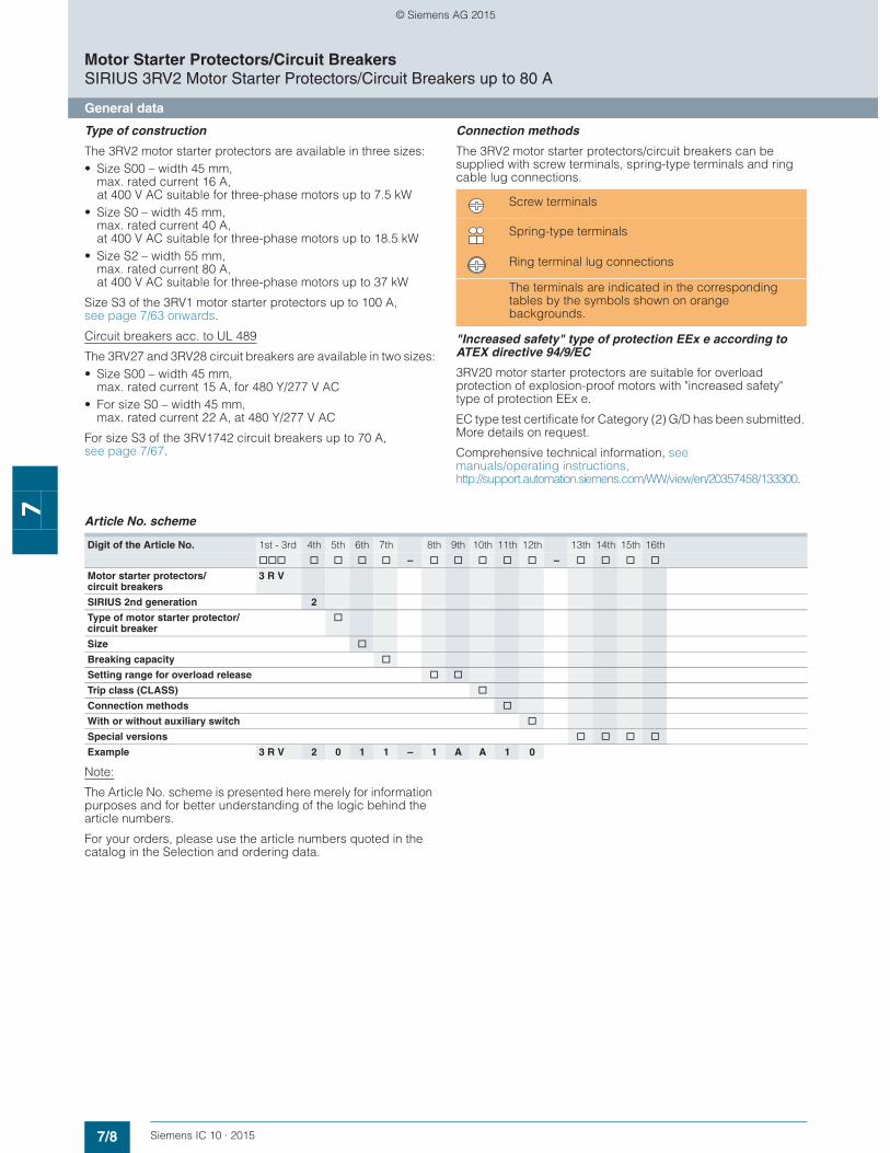
Type of construction
The 3RV2 motor starter protectors are available in three sizes:• Size S00 – width 45 mm,
max. rated current 16 A, at 400 V AC suitable for three-phase motors up to 7.5 kW
• Size S0 – width 45 mm, max. rated current 40 A, at 400 V AC suitable for three-phase motors up to 18.5 kW
• Size S2 – width 55 mm, max. rated current 80 A, at 400 V AC suitable for three-phase motors up to 37 kW
Size S3 of the 3RV1 motor starter protectors up to 100 A, see page 7/63 onwards.
Circuit breakers acc. to UL 489
The 3RV27 and 3RV28 circuit breakers are available in two sizes:• Size S00 – width 45 mm,
max. rated current 15 A, for 480 Y/277 V AC• For size S0 – width 45 mm,
max. rated current 22 A, at 480 Y/277 V AC
For size S3 of the 3RV1742 circuit breakers up to 70 A, see page 7/67.
Connection methods
The 3RV2 motor starter protectors/circuit breakers can be supplied with screw terminals, spring-type terminals and ring cable lug connections.
"Increased safety" type of protection EEx e according to ATEX directive 94/9/EC
3RV20 motor starter protectors are suitable for overload protection of explosion-proof motors with "increased safety" type of protection EEx e.
EC type test certificate for Category (2) G/D has been submitted. More details on request.
Comprehensive technical information, see manuals/operating instructions, http://support.automation.siemens.com/WW/view/en/20357458/133300.
Article No. scheme
Note:
The Article No. scheme is presented here merely for information purposes and for better understanding of the logic behind the article numbers.
For your orders, please use the article numbers quoted in the catalog in the Selection and ordering data.
Screw terminals
Spring-type terminals
Ring terminal lug connections
The terminals are indicated in the corresponding tables by the symbols shown on orange backgrounds.
Digit of the Article No. 1st - 3rd 4th 5th 6th 7th 8th 9th 10th 11th 12th 13th 14th 15th 16th
@@@ @ @ @ @ – @ @ @ @ @ – @ @ @ @
Motor starter protectors/circuit breakers
3 R V
SIRIUS 2nd generation 2
Type of motor starter protector/circuit breaker
@
Size @
Breaking capacity @
Setting range for overload release @ @
Trip class (CLASS) @
Connection methods @
With or without auxiliary switch @
Special versions @ @ @ @
Example 3 R V 2 0 1 1 – 1 A A 1 0
© Siemens AG 2015
7/9Siemens IC 10 · 2015
Motor Starter Protectors/Circuit BreakersSIRIUS 3RV2 Motor Starter Protectors/Circuit Breakers up to 80 A
General data
7
■ Benefits
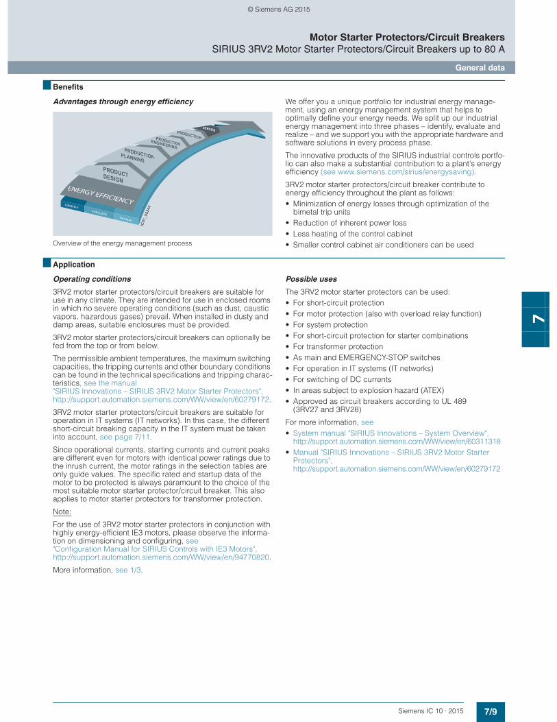
Advantages through energy efficiency
Overview of the energy management process
We offer you a unique portfolio for industrial energy manage-ment, using an energy management system that helps to optimally define your energy needs. We split up our industrial energy management into three phases – identify, evaluate and realize – and we support you with the appropriate hardware and software solutions in every process phase.
The innovative products of the SIRIUS industrial controls portfo-lio can also make a substantial contribution to a plant's energy efficiency (see www.siemens.com/sirius/energysaving).
3RV2 motor starter protectors/circuit breaker contribute to energy efficiency throughout the plant as follows:• Minimization of energy losses through optimization of the
bimetal trip units• Reduction of inherent power loss• Less heating of the control cabinet• Smaller control cabinet air conditioners can be used
■ Application
Operating conditions
3RV2 motor starter protectors/circuit breakers are suitable for use in any climate. They are intended for use in enclosed rooms in which no severe operating conditions (such as dust, caustic vapors, hazardous gases) prevail. When installed in dusty and damp areas, suitable enclosures must be provided.
3RV2 motor starter protectors/circuit breakers can optionally be fed from the top or from below.
The permissible ambient temperatures, the maximum switching capacities, the tripping currents and other boundary conditions can be found in the technical specifications and tripping charac-teristics, see the manual "SIRIUS Innovations – SIRIUS 3RV2 Motor Starter Protectors", http://support.automation.siemens.com/WW/view/en/60279172.
3RV2 motor starter protectors/circuit breakers are suitable for operation in IT systems (IT networks). In this case, the different short-circuit breaking capacity in the IT system must be taken into account, see page 7/11.
Since operational currents, starting currents and current peaks are different even for motors with identical power ratings due to the inrush current, the motor ratings in the selection tables are only guide values. The specific rated and startup data of the motor to be protected is always paramount to the choice of the most suitable motor starter protector/circuit breaker. This also applies to motor starter protectors for transformer protection.
Note:
For the use of 3RV2 motor starter protectors in conjunction with highly energy-efficient IE3 motors, please observe the informa-tion on dimensioning and configuring, see "Configuration Manual for SIRIUS Controls with IE3 Motors", http://support.automation.siemens.com/WW/view/en/94770820.
More information, see 1/3.
Possible uses
The 3RV2 motor starter protectors can be used:• For short-circuit protection • For motor protection (also with overload relay function) • For system protection • For short-circuit protection for starter combinations • For transformer protection • As main and EMERGENCY-STOP switches • For operation in IT systems (IT networks) • For switching of DC currents • In areas subject to explosion hazard (ATEX)• Approved as circuit breakers according to UL 489
(3RV27 and 3RV28)
For more information, see• System manual "SIRIUS Innovations – System Overview",
http://support.automation.siemens.com/WW/view/en/60311318• Manual "SIRIUS Innovations – SIRIUS 3RV2 Motor Starter
Protectors", http://support.automation.siemens.com/WW/view/en/60279172
IC01
_002
44
© Siemens AG 2015
7/10 Siemens IC 10 · 2015
Motor Starter Protectors/Circuit BreakersSIRIUS 3RV2 Motor Starter Protectors/Circuit Breakers up to 80 A
General data
7
■ Technical specifications
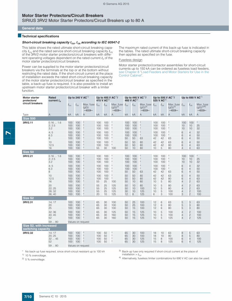
Short-circuit breaking capacity Icu, Ics according to IEC 60947-2
This table shows the rated ultimate short-circuit breaking capa-city Icu and the rated service short-circuit breaking capacity Ics of the 3RV2 motor starter protectors/circuit breakers with diffe-rent operating voltages dependent on the rated current In of the motor starter protectors/circuit breakers.
Power can be supplied to the motor starter protectors/circuit breakers via the terminals at the top or at the bottom without restricting the rated data. If the short-circuit current at the place of installation exceeds the rated short-circuit breaking capacity of the motor starter protector/circuit breaker as specified in the table, a back-up fuse is required. It is also possible to install an upstream motor starter protector/circuit breaker with a limiter function.
The maximum rated current of this back-up fuse is indicated in the tables. The rated ultimate short-circuit breaking capacity then applies as specified on the fuse.
Fuseless design
Motor starter protector/contactor assemblies for short-circuit currents up to 150 kA can be ordered as fuseless load feeders, see Chapter 8 "Load Feeders and Motor Starters for Use in the Control Cabinet".
° No back-up fuse required, since short-circuit resistant up to 100 kA1) 10 % overvoltage.2) 5 % overvoltage.
3) Back-up fuse only required if short-circuit current at the place of installation > Icu.
4) Alternatively, fuseless limiter combinations for 690 V AC can also be used.
Motor starter protectors/circuit breakers
Rated current In
Up to 240 V AC1) Up to 400 V AC1)/415 V AC2)
Up to 440 V AC1)/460 V AC2)
Up to 500 V AC1)/525 V AC2)
Up to 690 V AC1)
Icu Ics Max. fuse (gG)
Icu Ics Max. fuse (gG)3)
Icu Ics Max. fuse (gG)3)
Icu Ics Max. fuse (gG)3)
Icu Ics Max. fuse (gG)3)4)
Type A kA kA A kA kA A kA kA A kA kA A kA kA A
Size S003RV2.11 0.16 ... 1.6 100 100 ° 100 100 ° 100 100 ° 100 100 ° 100 100 °
2; 2.5 100 100 ° 100 100 ° 100 100 ° 100 100 ° 10 10 253.2 100 100 ° 100 100 ° 100 100 ° 100 100 ° 10 10 32
4; 5 100 100 ° 100 100 ° 100 100 ° 100 100 ° 6 4 326.3 100 100 ° 100 100 ° 100 100 ° 100 100 ° 6 4 508 100 100 ° 100 100 ° 50 50 63 42 42 63 6 4 50
10 100 100 ° 100 100 ° 50 50 80 42 42 63 6 4 5012.5 100 100 ° 100 100 ° 50 50 80 42 42 80 6 4 6316 100 100 ° 55 30 100 50 10 80 10 5 80 4 4 63
Size S03RV2.21 0.16 ... 1.6 100 100 ° 100 100 ° 100 100 ° 100 100 ° 100 100 °
2; 2.5 100 100 ° 100 100 ° 100 100 ° 100 100 ° 10 10 253.2 100 100 ° 100 100 ° 100 100 ° 100 100 ° 10 10 32
4; 5 100 100 ° 100 100 ° 100 100 ° 100 100 ° 6 4 326.3 100 100 ° 100 100 ° 100 100 ° 100 100 ° 6 4 508 100 100 ° 100 100 ° 50 50 63 42 42 63 6 4 50
10 100 100 ° 100 100 ° 50 50 80 42 42 63 6 4 5012.5 100 100 ° 100 100 ° 50 50 80 42 42 80 6 4 6316 100 100 ° 55 25 100 50 10 80 10 5 80 4 2 63
20 100 100 ° 55 25 125 50 10 80 10 5 80 4 2 6322; 25 100 100 ° 55 25 125 50 10 100 10 5 80 4 2 6328; 32 100 100 ° 55 25 125 30 10 125 10 5 100 4 2 10036; 40 100 100 ° 20 10 125 12 8 125 6 3 100 3 2 100
Size S23RV2.31 14; 17 100 100 ° 65 30 100 50 25 100 12 6 63 5 3 63
20 100 100 ° 65 30 100 50 25 100 12 6 80 5 3 8025 100 100 ° 65 30 100 50 15 100 12 6 80 5 3 80
32; 36 100 100 ° 65 30 125 50 15 125 10 5 100 4 2 10040; 45 100 100 ° 65 30 160 50 15 125 10 5 100 4 2 10052 100 100 ° 65 30 160 50 15 125 10 5 125 4 2 125
59 ... 80 Values on requestSize S2, with increased switching capacity3RV2.32 14; 17 100 100 ° 100 50 ° 65 30 100 18 10 63 8 5 63
20; 25 100 100 ° 100 50 ° 65 30 100 18 10 80 8 5 8032 ... 45 100 100 ° 100 50 ° 65 30 125 15 8 100 6 4 10052 100 100 ° 100 50 ° 65 30 125 15 8 125 6 4 125
59 ... 80 Values on request
© Siemens AG 2015
7/11Siemens IC 10 · 2015
Motor Starter Protectors/Circuit BreakersSIRIUS 3RV2 Motor Starter Protectors/Circuit Breakers up to 80 A
General data
7
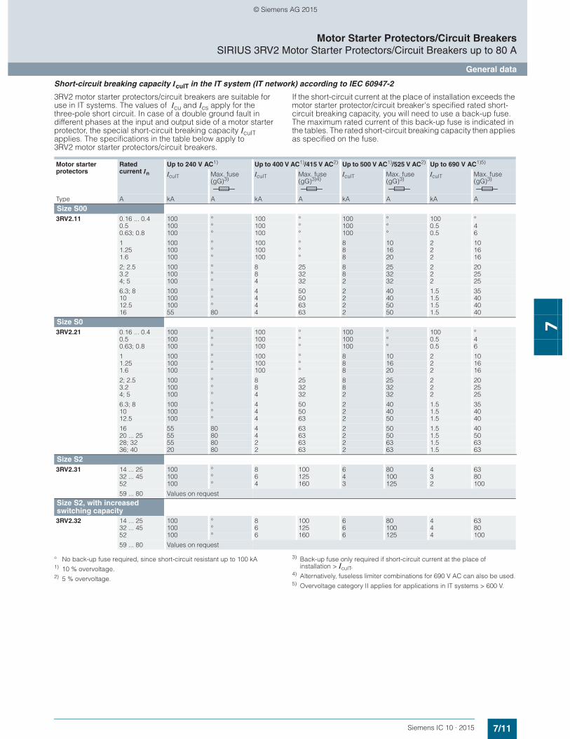
Short-circuit breaking capacity IcuIT in the IT system (IT network) according to IEC 60947-2
3RV2 motor starter protectors/circuit breakers are suitable for use in IT systems. The values of Icu and Ics apply for the three-pole short circuit. In case of a double ground fault in different phases at the input and output side of a motor starter protector, the special short-circuit breaking capacity IcuIT applies. The specifications in the table below apply to 3RV2 motor starter protectors/circuit breakers.
If the short-circuit current at the place of installation exceeds the motor starter protector/circuit breaker's specified rated short-circuit breaking capacity, you will need to use a back-up fuse. The maximum rated current of this back-up fuse is indicated in the tables. The rated short-circuit breaking capacity then applies as specified on the fuse.
° No back-up fuse required, since short-circuit resistant up to 100 kA1) 10 % overvoltage.2) 5 % overvoltage.
3) Back-up fuse only required if short-circuit current at the place of installation > IcuIT.
4) Alternatively, fuseless limiter combinations for 690 V AC can also be used.5) Overvoltage category II applies for applications in IT systems > 600 V.
Motor starter protectors
Rated current In
Up to 240 V AC1) Up to 400 V AC1)/415 V AC2) Up to 500 V AC1)/525 V AC2) Up to 690 V AC1)5)
IcuIT Max. fuse (gG)3)
IcuIT Max. fuse (gG)3)
IcuIT Max. fuse (gG)3)4)
IcuIT Max. fuse (gG)3)
Type A kA A kA A kA A kA A
Size S003RV2.11 0.16 ... 0.4 100 ° 100 ° 100 ° 100 °
0.5 100 ° 100 ° 100 ° 0.5 40.63; 0.8 100 ° 100 ° 100 ° 0.5 6
1 100 ° 100 ° 8 10 2 101.25 100 ° 100 ° 8 16 2 161.6 100 ° 100 ° 8 20 2 16
2; 2.5 100 ° 8 25 8 25 2 203.2 100 ° 8 32 8 32 2 254; 5 100 ° 4 32 2 32 2 25
6.3; 8 100 ° 4 50 2 40 1.5 3510 100 ° 4 50 2 40 1.5 4012.5 100 ° 4 63 2 50 1.5 4016 55 80 4 63 2 50 1.5 40
Size S03RV2.21 0.16 ... 0.4 100 ° 100 ° 100 ° 100 °
0.5 100 ° 100 ° 100 ° 0.5 40.63; 0.8 100 ° 100 ° 100 ° 0.5 6
1 100 ° 100 ° 8 10 2 101.25 100 ° 100 ° 8 16 2 161.6 100 ° 100 ° 8 20 2 16
2; 2.5 100 ° 8 25 8 25 2 203.2 100 ° 8 32 8 32 2 254; 5 100 ° 4 32 2 32 2 25
6.3; 8 100 ° 4 50 2 40 1.5 3510 100 ° 4 50 2 40 1.5 4012.5 100 ° 4 63 2 50 1.5 40
16 55 80 4 63 2 50 1.5 4020 ... 25 55 80 4 63 2 50 1.5 5028; 32 55 80 2 63 2 63 1.5 6336; 40 20 80 2 63 2 63 1.5 63
Size S23RV2.31 14 ... 25 100 ° 8 100 6 80 4 63
32 ... 45 100 ° 6 125 4 100 3 8052 100 ° 4 160 3 125 2 100
59 ... 80 Values on requestSize S2, with increased switching capacity3RV2.32 14 ... 25 100 ° 8 100 6 80 4 63
32 ... 45 100 ° 6 125 6 100 4 8052 100 ° 6 160 6 125 4 100
59 ... 80 Values on request
© Siemens AG 2015
7/12 Siemens IC 10 · 2015
Motor Starter Protectors/Circuit BreakersSIRIUS 3RV2 Motor Starter Protectors/Circuit Breakers up to 80 A
General data
7
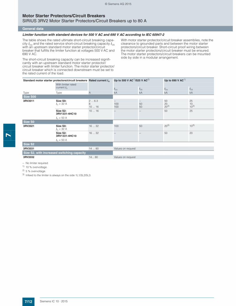
Limiter function with standard devices for 500 V AC and 690 V AC according to IEC 60947-2
The table shows the rated ultimate short-circuit breaking capa-city Icu and the rated service short-circuit breaking capacity Ics with an upstream standard motor starter protector/circuit breaker that fulfills the limiter function at voltages 500 V AC and 690 V AC.
The short-circuit breaking capacity can be increased signifi-cantly with an upstream standard motor starter protector/circuit breaker with limiter function. The motor starter protector/circuit breaker which is connected downstream must be set to the rated current of the load.
With motor starter protector/circuit breaker assemblies, note the clearance to grounded parts and between the motor starter protectors/circuit breaker. Short-circuit proof wiring between the motor starter protectors/circuit breaker must be ensured. The motor starter protectors/circuit breakers can be mounted side by side in a modular arrangement.
-- No limiter required1) 10 % overvoltage.2) 5 % overvoltage.3) Infeed to the limiter is always on the side 1L1/3L2/5L3.
Standard motor starter protectors/circuit breakers Rated current In Up to 500 V AC1)/525 V AC2) Up to 690 V AC1)
With limiter rated current In Icu Ics Icu Ics
Type Type A kA kA kA kA
Size S003RV2011 Size S0:
In = 32 A2 ... 6.3 -- -- 50 258 100 50 20 1010 ... 16 100 50 203) 103)
Size S2:3RV1331-4HC10
In = 50 A
10 ... 16 -- -- 50 25
Size S03RV2021 Size S0:
In = 32 A16 ... 32 100 50 203) 103)
Size S2:3RV1331-4HC10
In = 50 A
16 ... 32 -- -- 50 20
Size S23RV2031 14 ... 80 Values on request
Size S2, with increased switching capacity3RV2032 14... 80 Values on request
© Siemens AG 2015
7/13Siemens IC 10 · 2015
Motor Starter Protectors/Circuit BreakersSIRIUS 3RV2 Motor Starter Protectors/Circuit Breakers up to 80 A
General data
7
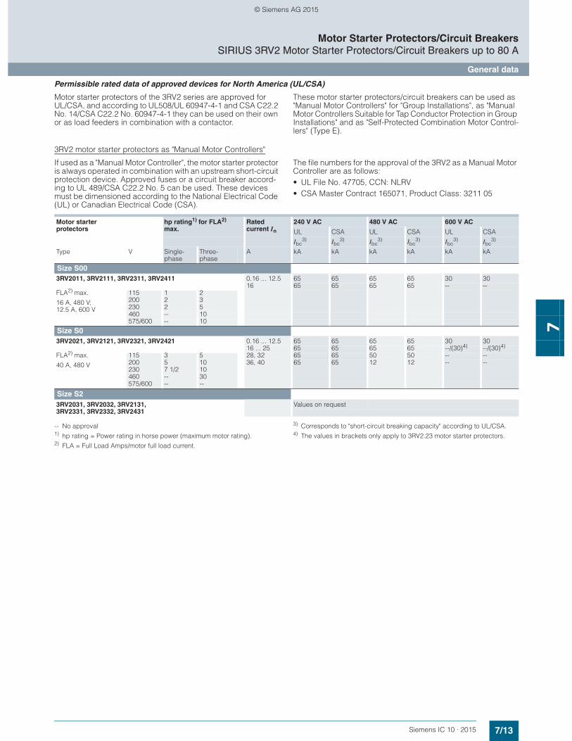
Permissible rated data of approved devices for North America (UL/CSA)
Motor starter protectors of the 3RV2 series are approved for UL/CSA, and according to UL508/UL 60947-4-1 and CSA C22.2 No. 14/CSA C22.2 No. 60947-4-1 they can be used on their own or as load feeders in combination with a contactor.
These motor starter protectors/circuit breakers can be used as "Manual Motor Controllers" for "Group Installations", as "Manual Motor Controllers Suitable for Tap Conductor Protection in Group Installations" and as "Self-Protected Combination Motor Control-lers" (Type E).
3RV2 motor starter protectors as "Manual Motor Controllers"
If used as a "Manual Motor Controller", the motor starter protector is always operated in combination with an upstream short-circuit protection device. Approved fuses or a circuit breaker accord-ing to UL 489/CSA C22.2 No. 5 can be used. These devices must be dimensioned according to the National Electrical Code (UL) or Canadian Electrical Code (CSA).
The file numbers for the approval of the 3RV2 as a Manual Motor Controller are as follows: • UL File No. 47705, CCN: NLRV • CSA Master Contract 165071, Product Class: 3211 05
-- No approval1) hp rating = Power rating in horse power (maximum motor rating).2) FLA = Full Load Amps/motor full load current.
3) Corresponds to "short-circuit breaking capacity" according to UL/CSA.4) The values in brackets only apply to 3RV2.23 motor starter protectors.
Motor starter protectors
hp rating1) for FLA2) max.
Rated current In
240 V AC 480 V AC 600 V AC
UL CSA UL CSA UL CSA
Ibc3) Ibc
3) Ibc3) Ibc
3) Ibc3) Ibc
3)
Type V Single-phase
Three-phase
A kA kA kA kA kA kA
Size S003RV2011, 3RV2111, 3RV2311, 3RV2411 0.16 ... 12.5 65 65 65 65 30 30
16 65 65 65 65 -- --FLA2) max.
16 A, 480 V; 12.5 A, 600 V
115 1 2200 2 3230 2 5460 -- 10575/600 -- 10
Size S03RV2021, 3RV2121, 3RV2321, 3RV2421 0.16 ... 12.5 65 65 65 65 30 30
16 ... 25 65 65 65 65 --/(30)4) --/(30)4)
FLA2) max.
40 A, 480 V
115 3 5 28, 32 65 65 50 50 -- --200 5 10 36, 40 65 65 12 12 -- --230 7 1/2 10460 -- 30575/600 -- --
Size S23RV2031, 3RV2032, 3RV2131, 3RV2331, 3RV2332, 3RV2431
Values on request
© Siemens AG 2015
7/14 Siemens IC 10 · 2015
Motor Starter Protectors/Circuit BreakersSIRIUS 3RV2 Motor Starter Protectors/Circuit Breakers up to 80 A
General data
7
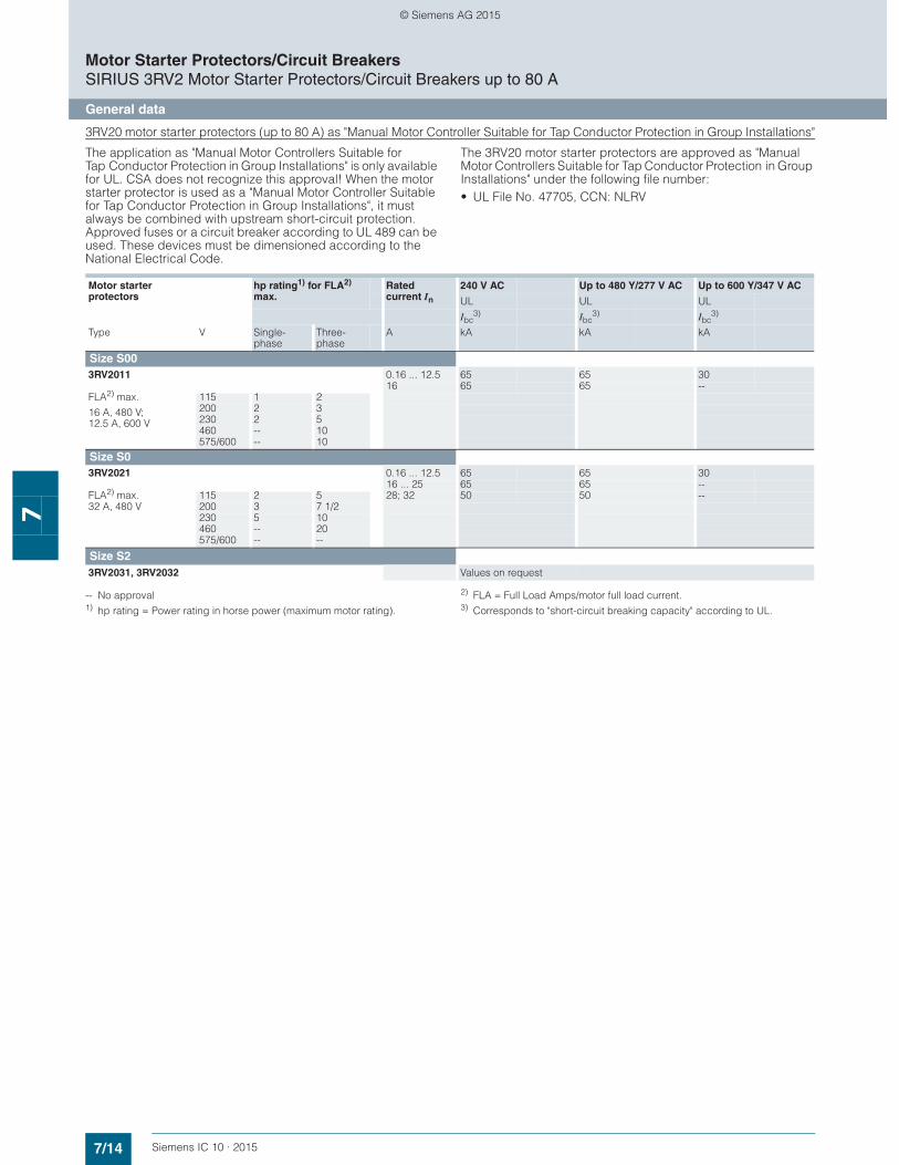
3RV20 motor starter protectors (up to 80 A) as "Manual Motor Controller Suitable for Tap Conductor Protection in Group Installations"
The application as "Manual Motor Controllers Suitable for Tap Conductor Protection in Group Installations" is only available for UL. CSA does not recognize this approval! When the motor starter protector is used as a "Manual Motor Controller Suitable for Tap Conductor Protection in Group Installations", it must always be combined with upstream short-circuit protection. Approved fuses or a circuit breaker according to UL 489 can be used. These devices must be dimensioned according to the National Electrical Code.
The 3RV20 motor starter protectors are approved as "Manual Motor Controllers Suitable for Tap Conductor Protection in Group Installations" under the following file number:• UL File No. 47705, CCN: NLRV
-- No approval1) hp rating = Power rating in horse power (maximum motor rating).
2) FLA = Full Load Amps/motor full load current.3) Corresponds to "short-circuit breaking capacity" according to UL.
Motor starter protectors
hp rating1) for FLA2) max.
Rated current In
240 V AC Up to 480 Y/277 V AC Up to 600 Y/347 V AC
UL UL UL
Ibc3) Ibc
3) Ibc3)
Type V Single-phase
Three-phase
A kA kA kA
Size S003RV2011 0.16 ... 12.5 65 65 30
16 65 65 --FLA2) max.
16 A, 480 V; 12.5 A, 600 V
115 1 2200 2 3230 2 5460 -- 10575/600 -- 10
Size S03RV2021 0.16 ... 12.5 65 65 30
16 ... 25 65 65 --FLA2) max. 115 2 5 28; 32 50 50 --32 A, 480 V 200 3 7 1/2
230 5 10460 -- 20575/600 -- --
Size S23RV2031, 3RV2032 Values on request
© Siemens AG 2015

7/15Siemens IC 10 · 2015
Motor Starter Protectors/Circuit BreakersSIRIUS 3RV2 Motor Starter Protectors/Circuit Breakers up to 80 A
General data
7
3RV20 motor starter protectors (up to 80 A) as "Self-Protected Combination Motor Controller (Type E)"
UL 508/UL 60947-4-1 approval demands 1-inch clearance and 2-inch creepage distance at line side for "Self-Protected Combination Motor Controller Type E".
Therefore, 3RV20 motor starter protectors of sizes S00 to S2 are approved according to UL 508/UL 60947-4-1 in combination with the terminal blocks listed below.
CSA does not require these extended clearances and creepage distances. According to CSA, these terminal blocks can be omitted when the device is used as a "Self-Protected Combination Motor Controller".
The 3RV20 motor starter protectors are approved as "Self-Protected Combination Motor Controllers" under the following file numbers: • UL File No. E156943, CCN: NKJH• CSA Master Contract 165071, Product Class: 3211 08
-- No approval1) hp rating = Power rating in horse power (maximum motor rating).2) FLA = Full Load Amps/motor full load current.
3) Corresponds to "short-circuit breaking capacity" according to UL/CSA.4) Not required for CSA.5) Alternatively, the 3RV2928-1K phase barrier can also be used.
3RV27 and 3RV28 motor starter protectors as "circuit breakers"
These motor starter protectors are approved as circuit breakers according to UL 489 and CSA 22.2 No. 5. They can be used therefore as upstream short-circuit protective devices for "Manual Motor Controllers" and "Manual Motor Controllers Suitable for Tap Conductor Protection in Group Installations".
3RV27 and 3RV28 motor starter protectors are approved as "circuit breakers" under the following file numbers:• UL File No. E235044, CCN: DIVQ• CSA Master Contract 165071, Product Class: 1432 01
-- No approval1) Corresponds to "short-circuit breaking capacity" according to UL.
Motor starter protectors
hp rating1) for FLA2) max.
Rated current In
Up to 240 V AC Up to 480 Y/277 V AC Up to 600 Y/347 V AC
UL CSA UL CSA UL CSA
Ibc3) Ibc
3) Ibc3) Ibc
3) Ibc3) Ibc
3)
Type V Single-phase
Three-phase A kA kA kA kA kA kA
Size S003RV2011 + 3RV2928-1H4)5) 0.16 ... 12.5 65 65 65 65 30 30
16 65 65 65 65 -- --FLA2) max.
16 A, 480 V;12.5 A, 600 V
115 1 2200 2 3230 2 5460 -- 10575/600 -- 10
Size S03RV2021 + 3RV2928-1H4)5) 0.16 ... 12.5 65 65 65 65 30 30
16 ... 25 65 65 65 65 -- --FLA2) max.
32 A, 480 V
115 2 5 28; 32 50 50 50 50 -- --200 3 7 1/2230 5 10460 -- 20575/600 -- --
Size S23RV2031/3RV2032 + 3RV2938-1K4) Values on request
Circuit breakers Rated current In 240 V AC 480 Y/277 V AC 600 Y/347 V AC
UL CSA UL CSA UL CSA
Ibc1) Ibc
1) Ibc1) Ibc
1) Ibc1) Ibc
1)
Type A kA kA kA kA kA kA
Size S003RV2711 0.16 ... 12.5 65 65 65 65 10 10
15 65 65 65 65 -- --
3RV2811 0.16 ... 12.5 65 65 65 65 10 1015 65 65 65 65 -- --
Size S03RV2721 20; 22 50 50 50 50 -- --
3RV2821 20; 22 50 50 50 50 -- --
© Siemens AG 2015
7/16 Siemens IC 10 · 2015
Motor Starter Protectors/Circuit BreakersSIRIUS 3RV2 Motor Starter Protectors/Circuit Breakers up to 80 A
General data
7
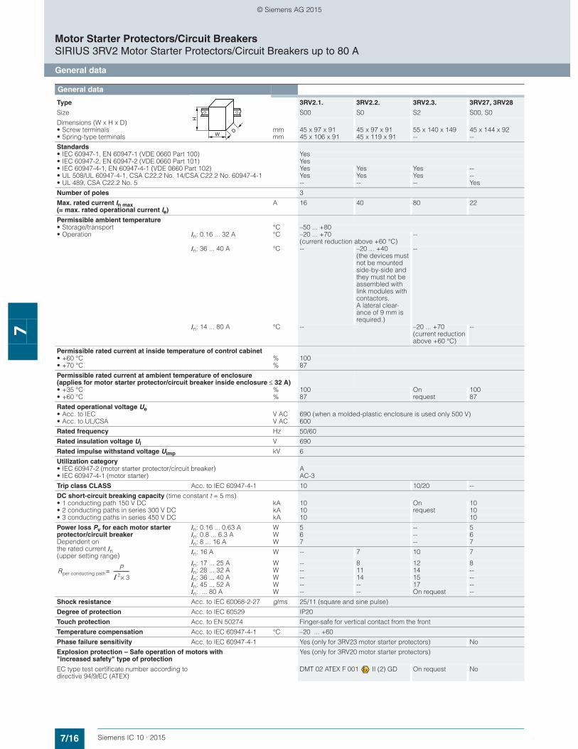
General data
Type 3RV2.1. 3RV2.2. 3RV2.3. 3RV27, 3RV28
Size S00 S0 S2 S00, S0
Dimensions (W x H x D) • Screw terminals• Spring-type terminals
mmmm
45 x 97 x 9145 x 106 x 91
45 x 97 x 9145 x 119 x 91
55 x 140 x 149--
45 x 144 x 92--
Standards • IEC 60947-1, EN 60947-1 (VDE 0660 Part 100) Yes• IEC 60947-2, EN 60947-2 (VDE 0660 Part 101) Yes• IEC 60947-4-1, EN 60947-4-1 (VDE 0660 Part 102) Yes Yes Yes --• UL 508/UL 60947-4-1, CSA C22.2 No. 14/CSA C22.2 No. 60947-4-1 Yes Yes Yes --• UL 489, CSA C22.2 No. 5 -- -- -- Yes
Number of poles 3
Max. rated current In max (= max. rated operational current Ie)
A 16 40 80 22
Permissible ambient temperature • Storage/transport °C –50 ... +80• Operation In: 0.16 ... 32 A °C –20 ... +70
(current reduction above +60 °C)--
In: 36 ... 40 A °C -- –20 ... +40 (the devices must not be mounted side-by-side and they must not be assembled with link modules with contactors. A lateral clear-ance of 9 mm is required.)
--
In: 14 ... 80 A °C -- –20 ... +70 (current reduction above +60 °C)
--
Permissible rated current at inside temperature of control cabinet • +60 °C % 100• +70 °C % 87
Permissible rated current at ambient temperature of enclosure(applies for motor starter protector/circuit breaker inside enclosure ≤ 32 A)
• +35 °C % 100 On request
100• +60 °C % 87 87
Rated operational voltage Ue • Acc. to IEC V AC 690 (when a molded-plastic enclosure is used only 500 V)• Acc. to UL/CSA V AC 600
Rated frequency Hz 50/60
Rated insulation voltage Ui V 690
Rated impulse withstand voltage Uimp kV 6
Utilization category • IEC 60947-2 (motor starter protector/circuit breaker) A• IEC 60947-4-1 (motor starter) AC-3
Trip class CLASS Acc. to IEC 60947-4-1 10 10/20 --
DC short-circuit breaking capacity (time constant t = 5 ms) • 1 conducting path 150 V DC kA 10 On
request10
• 2 conducting paths in series 300 V DC kA 10 10• 3 conducting paths in series 450 V DC kA 10 10
Power loss Pv for each motor starter protector/circuit breaker Dependent on the rated current In (upper setting range)
In: 0.16 ... 0.63 A W 5 -- 5In: 0.8 ... 6.3 A W 6 -- 6In: 8 ... 16 A W 7 -- 7
In: 16 A W -- 7 10 7
In: 17 ... 25 A W -- 8 12 8In: 28 ... 32 A W -- 11 14 --In: 36 ... 40 A W -- 14 15 --In: 45 ... 52 A W -- -- 17 --In: ... 80 A W -- -- On request --
Shock resistance Acc. to IEC 60068-2-27 g/ms 25/11 (square and sine pulse)
Degree of protection Acc. to IEC 60529 IP20
Touch protection Acc. to EN 50274 Finger-safe for vertical contact from the front
Temperature compensation Acc. to IEC 60947-4-1 °C –20 ... +60
Phase failure sensitivity Acc. to IEC 60947-4-1 Yes (only for 3RV23 motor starter protectors) No
Explosion protection – Safe operation of motors with "increased safety" type of protection
Yes (only for 3RV20 motor starter protectors)
EC type test certificate number according todirective 94/9/EC (ATEX)
DMT 02 ATEX F 001 II (2) GD On request No
W
H
D
Rper conducting pathP
Ι 2 3×--------------=
© Siemens AG 2015

7/17Siemens IC 10 · 2015
Motor Starter Protectors/Circuit BreakersSIRIUS 3RV2 Motor Starter Protectors/Circuit Breakers up to 80 A
General data
7
General data (continued)
Type 3RV2.1. 3RV2.2. 3RV2.3. 3RV27, 3RV28
Size S00 S0 S2 S00, S0
Dimensions (W x H x D) • Screw terminals• Spring-type terminals
mmmm
45 x 97 x 9145 x 106 x 91
45 x 97 x 9145 x 119 x 91
55 x 140 x 149--
45 x 144 x 92--
Isolating function Acc. to IEC 60947-2 YesMain and EMERGENCY-STOP switch characteristics (with corresponding accessories)
Acc. to DIN EN 60204-1 Yes
Protective separation between main and auxiliary circuits, required for PELV applications
Acc. to IEC 60947-1
• Up to 400 V +10 % Yes• Up to 415 V +5 % (higher voltages on request) Yes
Permissible mounting position Any, acc. to IEC 60447 start command "I" right-hand side or top
Mechanical endurance Operating cycles 100 000 52 A: 50 000, 80 A: On request
100 000
Electrical endurance Operating cycles 100 000 52 A: 50 000, 80 A: On request
100 000
Max. switching frequency per hour (motor starts) 1/h 15
Rated data of the auxiliary switches and signaling switches
Lateral auxiliary switch with 1 NO + 1 NC, 2 NO, 2 NC, 2 NO + 2 NC
Signaling switches
Transverse auxiliary switch with
1 CO 1 NO + 1 NC, 2 NO
Max. rated voltage
• Acc. to NEMA (UL) V AC 600 250
• Acc. to NEMA (CSA) V AC 600 250
Uninterrupted current A 10 5 2.5
Switching capacity 1 NO + 1 NC, 2 NO, 2 NC: A600, Q300;2 NO + 2 NC: A300, Q300
A600, Q300 B600, R300 C300, R300
W
H
D
Front transverse auxiliary switches
Switching capacity for different voltages
1 CO 1 NO + 1 NC, 2 NO
Rated operational current Ie• At AC-15, alternating voltage
- 24 V A 4 2- 230 V A 3 0.5
• At AC-12 = Ith, alternating voltage- 24 V A 10 2.5- 230 V A 10 2.5
• At DC-13, direct voltage L/R 200 ms- 24 V A 1 1- 48 V A -- 0.3- 60 V A -- 0.15- 110 V A 0.22 --- 220 V A 0.1 --
Minimum load capacity V 17mA 1
Front transverse solid-state compatible auxiliary switches
Switching capacity for different voltages
1 CO
Rated operational voltage Ue Alternating voltage V 125
Rated operational current Ie/AC-14 at Ue = 125 V A 0.1
Rated operational voltage Ue Direct voltage L/R 200 ms V 60
Rated operational current Ie/DC-13 at Ue = 60 V A 0.3
Minimum load capacity V 5mA 1
© Siemens AG 2015
7/18 Siemens IC 10 · 2015
Motor Starter Protectors/Circuit BreakersSIRIUS 3RV2 Motor Starter Protectors/Circuit Breakers up to 80 A
General data
7
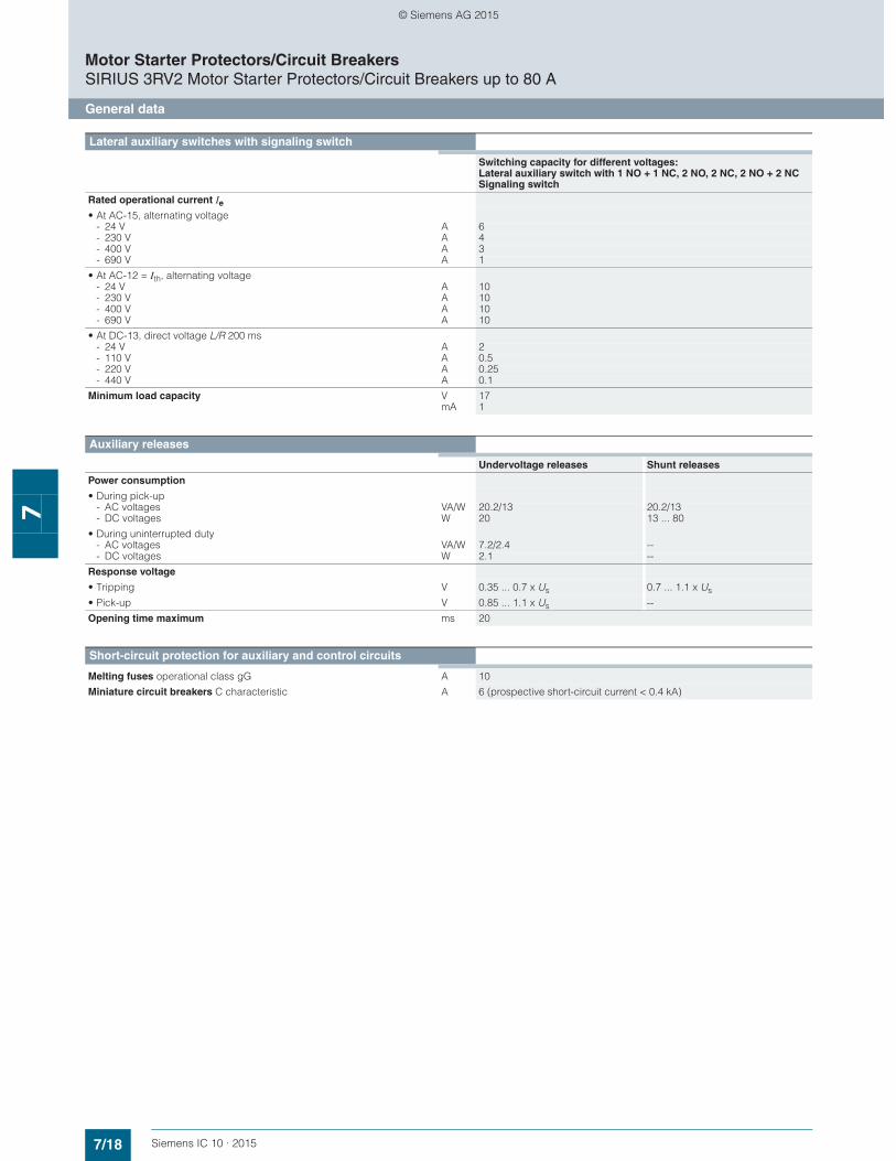
Lateral auxiliary switches with signaling switch
Switching capacity for different voltages: Lateral auxiliary switch with 1 NO + 1 NC, 2 NO, 2 NC, 2 NO + 2 NCSignaling switch
Rated operational current Ie
• At AC-15, alternating voltage- 24 V A 6- 230 V A 4- 400 V A 3- 690 V A 1
• At AC-12 = Ith, alternating voltage- 24 V A 10- 230 V A 10- 400 V A 10- 690 V A 10
• At DC-13, direct voltage L/R 200 ms- 24 V A 2- 110 V A 0.5- 220 V A 0.25- 440 V A 0.1
Minimum load capacity V 17mA 1
Auxiliary releases
Undervoltage releases Shunt releases
Power consumption
• During pick-up- AC voltages VA/W 20.2/13 20.2/13- DC voltages W 20 13 ... 80
• During uninterrupted duty- AC voltages VA/W 7.2/2.4 --- DC voltages W 2.1 --
Response voltage
• Tripping V 0.35 ... 0.7 x Us 0.7 ... 1.1 x Us
• Pick-up V 0.85 ... 1.1 x Us --
Opening time maximum ms 20
Short-circuit protection for auxiliary and control circuits
Melting fuses operational class gG A 10
Miniature circuit breakers C characteristic A 6 (prospective short-circuit current < 0.4 kA)
© Siemens AG 2015
7/19Siemens IC 10 · 2015
Motor Starter Protectors/Circuit BreakersSIRIUS 3RV2 Motor Starter Protectors/Circuit Breakers up to 80 A
General data
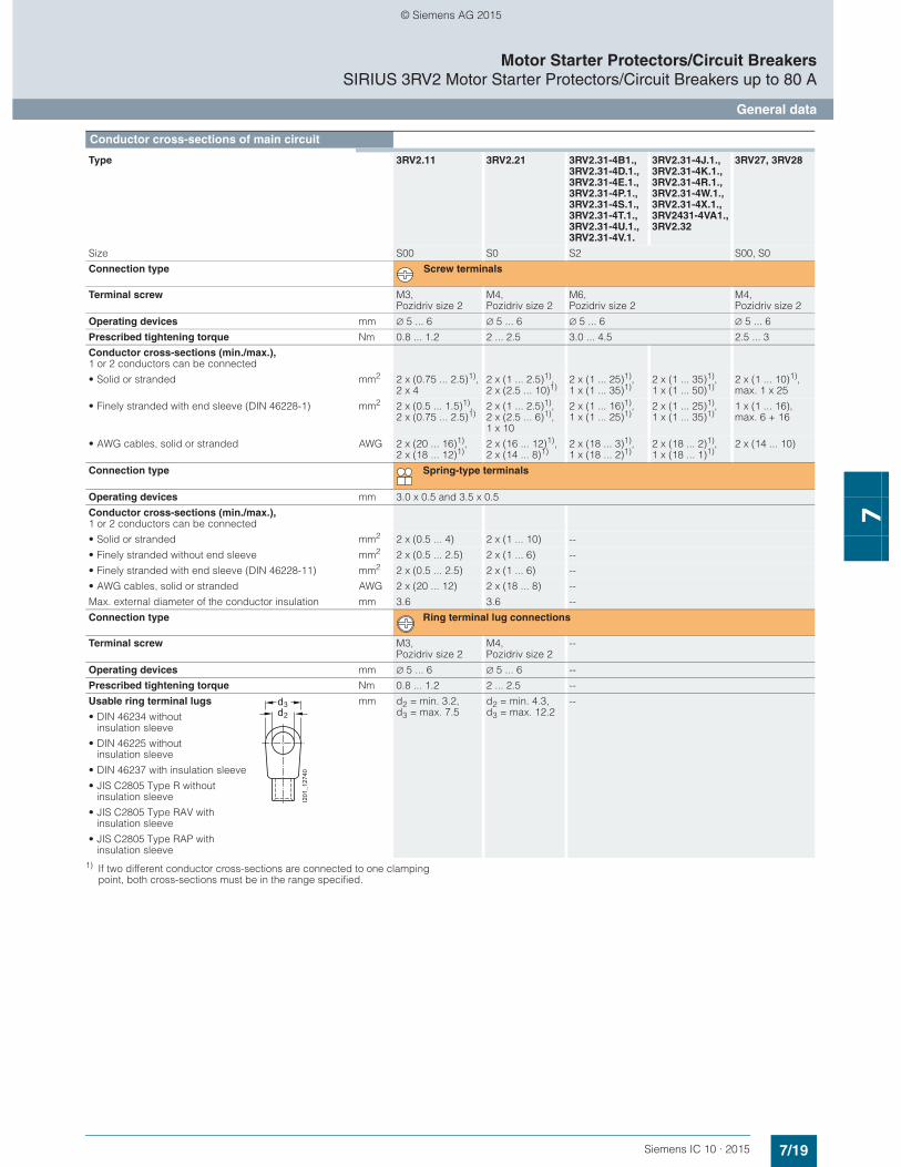
71) If two different conductor cross-sections are connected to one clamping
point, both cross-sections must be in the range specified.
Conductor cross-sections of main circuit
Type 3RV2.11 3RV2.21 3RV2.31-4B1.,3RV2.31-4D.1.,3RV2.31-4E.1.,3RV2.31-4P.1.,3RV2.31-4S.1.,3RV2.31-4T.1.,3RV2.31-4U.1.,3RV2.31-4V.1.
3RV2.31-4J.1., 3RV2.31-4K.1., 3RV2.31-4R.1., 3RV2.31-4W.1., 3RV2.31-4X.1.,3RV2431-4VA1., 3RV2.32
3RV27, 3RV28
Size S00 S0 S2 S00, S0
Connection type Screw terminals
Terminal screw M3, Pozidriv size 2
M4, Pozidriv size 2
M6, Pozidriv size 2
M4, Pozidriv size 2
Operating devices mm ∅ 5 ... 6 ∅ 5 ... 6 ∅ 5 ... 6 ∅ 5 ... 6
Prescribed tightening torque Nm 0.8 ... 1.2 2 ... 2.5 3.0 ... 4.5 2.5 ... 3
Conductor cross-sections (min./max.), 1 or 2 conductors can be connected
• Solid or stranded mm2 2 x (0.75 ... 2.5)1),2 x 4
2 x (1 ... 2.5)1), 2 x (2.5 ... 10)1)
2 x (1 ... 25)1), 1 x (1 ... 35)1)
2 x (1 ... 35)1), 1 x (1 ... 50)1)
2 x (1 ... 10)1),max. 1 x 25
• Finely stranded with end sleeve (DIN 46228-1) mm2 2 x (0.5 ... 1.5)1), 2 x (0.75 ... 2.5)1)
2 x (1 ... 2.5)1), 2 x (2.5 ... 6)1),1 x 10
2 x (1 ... 16)1), 1 x (1 ... 25)1)
2 x (1 ... 25)1), 1 x (1 ... 35)1)
1 x (1 ... 16),max. 6 + 16
• AWG cables, solid or stranded AWG 2 x (20 ... 16)1), 2 x (18 ... 12)1)
2 x (16 ... 12)1), 2 x (14 ... 8)1)
2 x (18 ... 3)1), 1 x (18 ... 2)1)
2 x (18 ... 2)1), 1 x (18 ... 1)1)
2 x (14 ... 10)
Connection type Spring-type terminals
Operating devices mm 3.0 x 0.5 and 3.5 x 0.5
Conductor cross-sections (min./max.), 1 or 2 conductors can be connected
• Solid or stranded mm2 2 x (0.5 ... 4) 2 x (1 ... 10) --
• Finely stranded without end sleeve mm2 2 x (0.5 ... 2.5) 2 x (1 ... 6) --
• Finely stranded with end sleeve (DIN 46228-11) mm2 2 x (0.5 ... 2.5) 2 x (1 ... 6) --
• AWG cables, solid or stranded AWG 2 x (20 ... 12) 2 x (18 ... 8) --
Max. external diameter of the conductor insulation mm 3.6 3.6 --
Connection type Ring terminal lug connections
Terminal screw M3, Pozidriv size 2
M4, Pozidriv size 2
--
Operating devices mm ∅ 5 ... 6 ∅ 5 ... 6 --
Prescribed tightening torque Nm 0.8 ... 1.2 2 ... 2.5 --
Usable ring terminal lugs mm d2 = min. 3.2, d3 = max. 7.5
d2 = min. 4.3, d3 = max. 12.2
--
• DIN 46234 without insulation sleeve
• DIN 46225 withoutinsulation sleeve
• DIN 46237 with insulation sleeve
• JIS C2805 Type R without insulation sleeve
• JIS C2805 Type RAV with insulation sleeve
• JIS C2805 Type RAP with insulation sleeve
d2
d3
I201
_127
40
© Siemens AG 2015
7/20 Siemens IC 10 · 2015
Motor Starter Protectors/Circuit BreakersSIRIUS 3RV2 Motor Starter Protectors/Circuit Breakers up to 80 A
General data
7
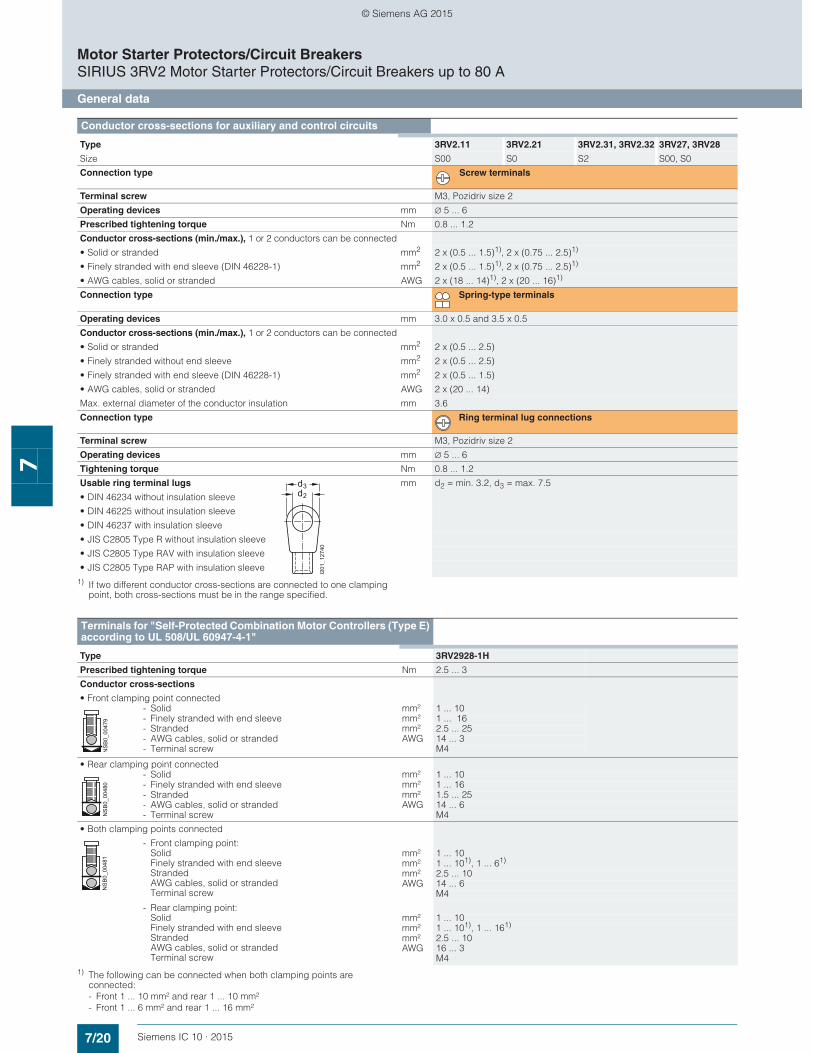
1) If two different conductor cross-sections are connected to one clamping point, both cross-sections must be in the range specified.
1) The following can be connected when both clamping points are connected:- Front 1 ... 10 mm² and rear 1 ... 10 mm²- Front 1 ... 6 mm² and rear 1 ... 16 mm²
Conductor cross-sections for auxiliary and control circuits
Type 3RV2.11 3RV2.21 3RV2.31, 3RV2.32 3RV27, 3RV28
Size S00 S0 S2 S00, S0
Connection type Screw terminals
Terminal screw M3, Pozidriv size 2
Operating devices mm ∅ 5 ... 6
Prescribed tightening torque Nm 0.8 ... 1.2
Conductor cross-sections (min./max.), 1 or 2 conductors can be connected
• Solid or stranded mm2 2 x (0.5 ... 1.5)1), 2 x (0.75 ... 2.5)1)
• Finely stranded with end sleeve (DIN 46228-1) mm2 2 x (0.5 ... 1.5)1), 2 x (0.75 ... 2.5)1)
• AWG cables, solid or stranded AWG 2 x (18 ... 14)1), 2 x (20 ... 16)1)
Connection type Spring-type terminals
Operating devices mm 3.0 x 0.5 and 3.5 x 0.5
Conductor cross-sections (min./max.), 1 or 2 conductors can be connected
• Solid or stranded mm2 2 x (0.5 ... 2.5)
• Finely stranded without end sleeve mm2 2 x (0.5 ... 2.5)
• Finely stranded with end sleeve (DIN 46228-1) mm2 2 x (0.5 ... 1.5)
• AWG cables, solid or stranded AWG 2 x (20 ... 14)
Max. external diameter of the conductor insulation mm 3.6
Connection type Ring terminal lug connections
Terminal screw M3, Pozidriv size 2
Operating devices mm ∅ 5 ... 6
Tightening torque Nm 0.8 ... 1.2
Usable ring terminal lugs mm d2 = min. 3.2, d3 = max. 7.5
• DIN 46234 without insulation sleeve
• DIN 46225 without insulation sleeve
• DIN 46237 with insulation sleeve
• JIS C2805 Type R without insulation sleeve
• JIS C2805 Type RAV with insulation sleeve
• JIS C2805 Type RAP with insulation sleeve
d2
d3
I201
_127
40
Terminals for "Self-Protected Combination Motor Controllers (Type E) according to UL 508/UL 60947-4-1"
Type 3RV2928-1H
Prescribed tightening torque Nm 2.5 ... 3
Conductor cross-sections
• Front clamping point connected
- Solid mm² 1 ... 10- Finely stranded with end sleeve mm² 1 ... 16- Stranded mm² 2.5 ... 25- AWG cables, solid or stranded AWG 14 ... 3- Terminal screw M4
• Rear clamping point connected
- Solid mm² 1 ... 10- Finely stranded with end sleeve mm² 1 ... 16- Stranded mm² 1.5 ... 25- AWG cables, solid or stranded AWG 14 ... 6- Terminal screw M4
• Both clamping points connected
- Front clamping point:SolidFinely stranded with end sleeveStrandedAWG cables, solid or strandedTerminal screw
mm² 1 ... 10mm² 1 ... 101), 1 ... 61)
mm² 2.5 ... 10AWG 14 ... 6
M4
- Rear clamping point:SolidFinely stranded with end sleeveStrandedAWG cables, solid or strandedTerminal screw
mm² 1 ... 10mm² 1 ... 101), 1 ... 161)
mm² 2.5 ... 10AWG 16 ... 3
M4
NS
B0_
0047
9N
SB
0_00
480
NS
B0_
0048
1
© Siemens AG 2015
7/21Siemens IC 10 · 2015* You can order this quantity or a multiple thereof.Illustrations are approximate
Motor Starter Protectors/Circuit BreakersSIRIUS 3RV2 Motor Starter Protectors up to 80 A
For motor protection
7
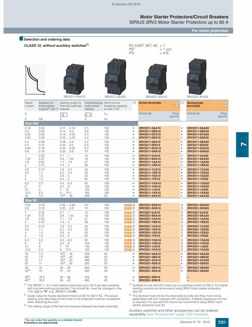
■ Selection and ordering data
CLASS 10, without auxiliary switches1) PU (UNIT, SET, M) = 1PS* = 1 unitPG = 41E
1) The 3RV20.1-..A.0 motor starter protectors up to 32 A are also available with ring terminal lug connection. The Article No. must be changed in the 11th digit to "4": e.g. 3RV2011-0AA40.
2) Guide value for 4-pole standard motors at 50 Hz 400 V AC. The actual starting and rated data of the motor to be protected must be considered when selecting the units.
3) The setting range of the thermal overload releases has been extended.
4) Suitable for use with IE3 motors up to a starting current of 256 A. For higher starting currents we recommend using 3RV2 motor starter protectors size S2.
5) The devices must not be mounted side-by-side and they must not be assembled with link modules with contactors. A lateral clearance of 9 mm is required. For use with IE3 motors we recommend using 3RV2 motor starter protectors size S2.
Auxiliary switches and other accessories can be ordered separately (see "Accessories" page 7/32 onwards).
Rated current
Suitable for three-phase motors2) with P
Setting range for thermal overload release
Instantaneous overcurrent release
Short-circuit breaking capacity at 400 V AC
DT Screw terminals DT Spring-type terminals
In Icu Article No. Priceper PU
Article No. Priceper PU
A kW A A kA
Size S000.16 0.04 0.11 ... 0.16 2.1 100 } 3RV2011-0AA10 } 3RV2011-0AA200.2 0.06 0.14 ... 0.2 2.6 100 } 3RV2011-0BA10 } 3RV2011-0BA200.25 0.06 0.18 ... 0.25 3.3 100 } 3RV2011-0CA10 } 3RV2011-0CA200.32 0.09 0.22 ... 0.32 4.2 100 } 3RV2011-0DA10 } 3RV2011-0DA20
0.4 0.09 0.28 ... 0.4 5.2 100 } 3RV2011-0EA10 } 3RV2011-0EA200.5 0.12 0.35 ... 0.5 6.5 100 } 3RV2011-0FA10 } 3RV2011-0FA200.63 0.18 0.45 ... 0.63 8.2 100 } 3RV2011-0GA10 } 3RV2011-0GA200.8 0.18 0.55 ... 0.8 10 100 } 3RV2011-0HA10 } 3RV2011-0HA20
1 0.25 0.7 ... 1 13 100 } 3RV2011-0JA10 } 3RV2011-0JA201.25 0.37 0.9 ... 1.25 16 100 } 3RV2011-0KA10 } 3RV2011-0KA201.6 0.55 1.1 ... 1.6 21 100 } 3RV2011-1AA10 } 3RV2011-1AA202 0.75 1.4 ... 2 26 100 } 3RV2011-1BA10 } 3RV2011-1BA20
2.5 0.75 1.8 ... 2.5 33 100 } 3RV2011-1CA10 } 3RV2011-1CA203.2 1.1 2.2 ... 3.2 42 100 } 3RV2011-1DA10 } 3RV2011-1DA204 1.5 2.8 ... 4 52 100 } 3RV2011-1EA10 } 3RV2011-1EA205 1.5 3.5 ... 5 65 100 } 3RV2011-1FA10 } 3RV2011-1FA20
6.3 2.2 4.5 ... 6.3 82 100 } 3RV2011-1GA10 } 3RV2011-1GA208 3 5.5 ... 8 104 100 } 3RV2011-1HA10 } 3RV2011-1HA2010 4 7 ... 10 130 100 } 3RV2011-1JA10 } 3RV2011-1JA2012.5 5.5 9 ... 12.5 163 100 } 3RV2011-1KA10 } 3RV2011-1KA2016 7.5 103) ... 16 208 55 } 3RV2011-4AA10 } 3RV2011-4AA20
Size S00.63 0.18 0.45 ... 0.63 8.2 100 B 3RV2021-0GA10 B 3RV2021-0GA200.8 0.18 0.55 ... 0.8 10 100 B 3RV2021-0HA10 B 3RV2021-0HA20
1 0.25 0.7 ... 1 13 100 B 3RV2021-0JA10 B 3RV2021-0JA201.25 0.37 0.9 ... 1.25 16 100 B 3RV2021-0KA10 B 3RV2021-0KA201.6 0.55 1.1 ... 1.6 21 100 B 3RV2021-1AA10 B 3RV2021-1AA202 0.75 1.4 ... 2 26 100 B 3RV2021-1BA10 B 3RV2021-1BA20
2.5 0.75 1.8 ... 2.5 33 100 B 3RV2021-1CA10 B 3RV2021-1CA203.2 1.1 2.2 ... 3.2 42 100 B 3RV2021-1DA10 B 3RV2021-1DA204 1.5 2.8 ... 4 52 100 B 3RV2021-1EA10 B 3RV2021-1EA205 1.5 3.5 ... 5 65 100 B 3RV2021-1FA10 B 3RV2021-1FA20
6.3 2.2 4.5 ... 6.3 82 100 B 3RV2021-1GA10 B 3RV2021-1GA208 3 5.5 ... 8 104 100 B 3RV2021-1HA10 B 3RV2021-1HA2010 4 7 ... 10 130 100 B 3RV2021-1JA10 B 3RV2021-1JA2012.5 5.5 9 ... 12.5 163 100 B 3RV2021-1KA10 B 3RV2021-1KA20
16 7.5 103) ... 16 208 55 } 3RV2021-4AA10 } 3RV2021-4AA2020 7.5 133) ... 20 260 55 } 3RV2021-4BA10 } 3RV2021-4BA2022 11 163) ... 22 286 55 } 3RV2021-4CA10 } 3RV2021-4CA2025 11 183) ... 25 325 55 } 3RV2021-4DA10 } 3RV2021-4DA20
28 15 23 ... 28 364 55 } 3RV2021-4NA10 } 3RV2021-4NA20324) 15 27 ... 32 400 55 } 3RV2021-4EA10 } 3RV2021-4EA20
365) 18.5 30 ... 36 432 20 } 3RV2021-4PA10 --405) 18.5 34 ... 40 480 20 } 3RV2021-4FA10 --
3RV2011-0EA20 3RV2021-4AA10 3RV2021-4AA203RV2011-0AA10
© Siemens AG 2015
7/22 Siemens IC 10 · 2015* You can order this quantity or a multiple thereof.
Illustrations are approximate
Motor Starter Protectors/Circuit BreakersSIRIUS 3RV2 Motor Starter Protectors up to 80 A
For motor protection
7
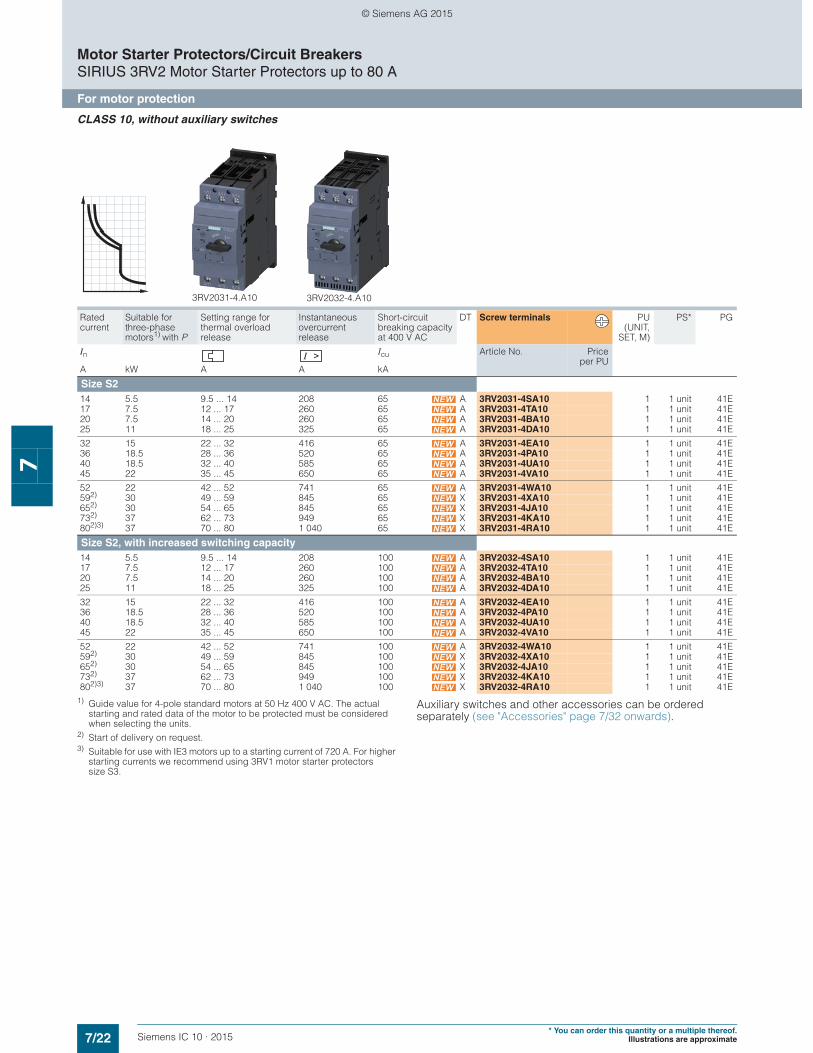
CLASS 10, without auxiliary switches
1) Guide value for 4-pole standard motors at 50 Hz 400 V AC. The actual starting and rated data of the motor to be protected must be considered when selecting the units.
2) Start of delivery on request.3) Suitable for use with IE3 motors up to a starting current of 720 A. For higher
starting currents we recommend using 3RV1 motor starter protectors size S3.
Auxiliary switches and other accessories can be ordered separately (see "Accessories" page 7/32 onwards).
Rated current
Suitable for three-phase motors1) with P
Setting range for thermal overload release
Instantaneous overcurrent release
Short-circuit breaking capacity at 400 V AC
DT Screw terminals PU(UNIT,
SET, M)
PS* PG
In Icu Article No. Priceper PU
A kW A A kA
Size S214 5.5 9.5 ... 14 208 65 A 3RV2031-4SA10 1 1 unit 41E17 7.5 12 ... 17 260 65 A 3RV2031-4TA10 1 1 unit 41E20 7.5 14 ... 20 260 65 A 3RV2031-4BA10 1 1 unit 41E25 11 18 ... 25 325 65 A 3RV2031-4DA10 1 1 unit 41E
32 15 22 ... 32 416 65 A 3RV2031-4EA10 1 1 unit 41E36 18.5 28 ... 36 520 65 A 3RV2031-4PA10 1 1 unit 41E40 18.5 32 ... 40 585 65 A 3RV2031-4UA10 1 1 unit 41E45 22 35 ... 45 650 65 A 3RV2031-4VA10 1 1 unit 41E
52 22 42 ... 52 741 65 A 3RV2031-4WA10 1 1 unit 41E592) 30 49 ... 59 845 65 X 3RV2031-4XA10 1 1 unit 41E652) 30 54 ... 65 845 65 X 3RV2031-4JA10 1 1 unit 41E732) 37 62 ... 73 949 65 X 3RV2031-4KA10 1 1 unit 41E802)3) 37 70 ... 80 1 040 65 X 3RV2031-4RA10 1 1 unit 41E
Size S2, with increased switching capacity14 5.5 9.5 ... 14 208 100 A 3RV2032-4SA10 1 1 unit 41E17 7.5 12 ... 17 260 100 A 3RV2032-4TA10 1 1 unit 41E20 7.5 14 ... 20 260 100 A 3RV2032-4BA10 1 1 unit 41E25 11 18 ... 25 325 100 A 3RV2032-4DA10 1 1 unit 41E
32 15 22 ... 32 416 100 A 3RV2032-4EA10 1 1 unit 41E36 18.5 28 ... 36 520 100 A 3RV2032-4PA10 1 1 unit 41E40 18.5 32 ... 40 585 100 A 3RV2032-4UA10 1 1 unit 41E45 22 35 ... 45 650 100 A 3RV2032-4VA10 1 1 unit 41E
52 22 42 ... 52 741 100 A 3RV2032-4WA10 1 1 unit 41E592) 30 49 ... 59 845 100 X 3RV2032-4XA10 1 1 unit 41E652) 30 54 ... 65 845 100 X 3RV2032-4JA10 1 1 unit 41E732) 37 62 ... 73 949 100 X 3RV2032-4KA10 1 1 unit 41E802)3) 37 70 ... 80 1 040 100 X 3RV2032-4RA10 1 1 unit 41E
3RV2032-4.A103RV2031-4.A10
© Siemens AG 2015

7/23Siemens IC 10 · 2015* You can order this quantity or a multiple thereof.Illustrations are approximate
Motor Starter Protectors/Circuit BreakersSIRIUS 3RV2 Motor Starter Protectors up to 80 A
For motor protection
7
CLASS 10, with transverse auxiliary switch (1 NO + 1 NC)
PU (UNIT, SET, M) = 1PS* = 1 unitPG = 41E
1) Guide value for 4-pole standard motors at 50 Hz 400 V AC. The actual starting and rated data of the motor to be protected must be considered when selecting the units.
2) The setting range of the thermal overload releases has been extended.3) Suitable for use with IE3 motors up to a starting current of 256 A. For higher
starting currents we recommend using 3RV2 motor starter protectors size S2.
4) The devices must not be mounted side-by-side and they must not be assembled with link modules with contactors. A lateral clearance of 9 mm is required. For use with IE3 motors we recommend using 3RV2 motor starter protectors size S2.
Auxiliary switches and other accessories can be ordered separately (see "Accessories" page 7/32 onwards).
Rated current
Suitable for three-phase motors1) with P
Setting range for thermal overload release
Instantaneous overcurrent release
Short-circuit breaking capacity at 400 V AC
DT Screw terminals DT Spring-type terminals
In Icu Article No. Priceper PU
Article No. Priceper PU
A kW A A kA
Size S000.16 0.04 0.11 ... 0.16 2.1 100 } 3RV2011-0AA15 } 3RV2011-0AA250.2 0.06 0.14 ... 0.2 2.6 100 } 3RV2011-0BA15 } 3RV2011-0BA250.25 0.06 0.18 ... 0.25 3.3 100 } 3RV2011-0CA15 } 3RV2011-0CA250.32 0.09 0.22 ... 0.32 4.2 100 } 3RV2011-0DA15 } 3RV2011-0DA25
0.4 0.09 0.28 ... 0.4 5.2 100 } 3RV2011-0EA15 } 3RV2011-0EA250.5 0.12 0.35 ... 0.5 6.5 100 } 3RV2011-0FA15 } 3RV2011-0FA250.63 0.18 0.45 ... 0.63 8.2 100 } 3RV2011-0GA15 } 3RV2011-0GA250.8 0.18 0.55 ... 0.8 10 100 } 3RV2011-0HA15 } 3RV2011-0HA25
1 0.25 0.7 ... 1 13 100 } 3RV2011-0JA15 } 3RV2011-0JA251.25 0.37 0.9 ... 1.25 16 100 } 3RV2011-0KA15 } 3RV2011-0KA251.6 0.55 1.1 ... 1.6 21 100 } 3RV2011-1AA15 } 3RV2011-1AA252 0.75 1.4 ... 2 26 100 } 3RV2011-1BA15 } 3RV2011-1BA25
2.5 0.75 1.8 ... 2.5 33 100 } 3RV2011-1CA15 } 3RV2011-1CA253.2 1.1 2.2 ... 3.2 42 100 } 3RV2011-1DA15 } 3RV2011-1DA254 1.5 2.8 ... 4 52 100 } 3RV2011-1EA15 } 3RV2011-1EA255 1.5 3.5 ... 5 65 100 } 3RV2011-1FA15 } 3RV2011-1FA25
6.3 2.2 4.5 ... 6.3 82 100 } 3RV2011-1GA15 } 3RV2011-1GA258 3 5.5 ... 8 104 100 } 3RV2011-1HA15 } 3RV2011-1HA2510 4 7 ... 10 130 100 } 3RV2011-1JA15 } 3RV2011-1JA2512.5 5.5 9 ... 12.5 163 100 } 3RV2011-1KA15 } 3RV2011-1KA2516 7.5 102) ... 16 208 55 } 3RV2011-4AA15 } 3RV2011-4AA25
Size S016 7.5 102) ... 16 208 55 } 3RV2021-4AA15 } 3RV2021-4AA2520 7.5 132) ... 20 260 55 } 3RV2021-4BA15 } 3RV2021-4BA2522 11 162) ... 22 286 55 } 3RV2021-4CA15 } 3RV2021-4CA2525 11 182) ... 25 325 55 } 3RV2021-4DA15 } 3RV2021-4DA25
28 15 23 ... 28 364 55 } 3RV2021-4NA15 } 3RV2021-4NA25323) 15 27 ... 32 400 55 } 3RV2021-4EA15 } 3RV2021-4EA25
364) 18.5 30 ... 36 432 20 } 3RV2021-4PA15 --404) 18.5 34 ... 40 480 20 } 3RV2021-4FA15 --
3RV2011-4AA15 with integrated transverse auxiliary switch
3RV2011-0EA25with integrated transverse auxiliary switch
3RV2021-4AA15with integrated transverse auxiliary switch
3RV2021-4AA25with integrated transverse auxiliary switch
© Siemens AG 2015

7/24 Siemens IC 10 · 2015* You can order this quantity or a multiple thereof.
Illustrations are approximate
Motor Starter Protectors/Circuit BreakersSIRIUS 3RV2 Motor Starter Protectors up to 80 A
For motor protection
7
CLASS 20, without auxiliary switches
1) Guide value for 4-pole standard motors at 50 Hz 400 V AC. The actual starting and rated data of the motor to be protected must be considered when selecting the units.
2) Start of delivery on request.
Auxiliary switches and other accessories can be ordered separately (see "Accessories" page 7/32 onwards).
Rated current
Suitable for three-phase motors1) with P
Setting range for thermal overload release
Instantaneous overcurrent release
Short-circuit breaking capacity at 400 V AC
DT Screw terminals PU(UNIT,
SET, M)
PS* PG
In Icu Article No. Priceper PU
A kW A A kA
Size S214 5.5 9.5 ... 14 208 65 A 3RV2031-4SB10 1 1 unit 41E17 7.5 12 ... 17 260 65 A 3RV2031-4TB10 1 1 unit 41E20 7.5 14 ... 20 260 65 A 3RV2031-4BB10 1 1 unit 41E25 11 18 ... 25 325 65 A 3RV2031-4DB10 1 1 unit 41E
32 15 22 ... 32 416 65 A 3RV2031-4EB10 1 1 unit 41E36 18.5 28 ... 36 520 65 A 3RV2031-4PB10 1 1 unit 41E40 18.5 32 ... 40 585 65 A 3RV2031-4UB10 1 1 unit 41E45 22 35 ... 45 650 65 A 3RV2031-4VB10 1 1 unit 41E
52 22 42 ... 52 741 65 A 3RV2031-4WB10 1 1 unit 41E592) 30 49 ... 59 845 65 X 3RV2031-4XB10 1 1 unit 41E652) 30 54 ... 65 845 65 X 3RV2031-4JB10 1 1 unit 41E
3RV2031-4WB103RV2031-4.B10
© Siemens AG 2015

7/25Siemens IC 10 · 2015* You can order this quantity or a multiple thereof.Illustrations are approximate
Motor Starter Protectors/Circuit BreakersSIRIUS 3RV2 Motor Starter Protectors up to 80 A
For motor protection with overload relay function
7
■ Selection and ordering data
CLASS 10, with overload relay function (automatic RESET), without auxiliary switches
1) Guide value for 4-pole standard motors at 50 Hz 400 V AC. The actual starting and rated data of the motor to be protected must be considered when selecting the units.
2) Accessories for mounting on the right and 3RV2915 three-phase busbars cannot be used.
3) The setting range of the thermal overload releases has been extended.4) Suitable for use with IE3 motors up to a starting current of 256 A. For higher
starting currents we recommend using 3RV2 motor starter protectors size S2.
5) Start of delivery on request.6) Suitable for use with IE3 motors up to a starting current of 720 A. For higher
starting currents we recommend using 3RV1 motor starter protectors size S3.
Auxiliary switches and other accessories can be ordered separately (see "Accessories" page 7/32 onwards).
Rated current
Suitable for three-phase motors1) with P
Setting range for thermal overload release
Instantaneous overcurrent release
Short-circuit breaking capacity at 400 V AC
DT Screw terminals PU(UNIT,
SET, M)
PS* PG
In Icu Article No. Priceper PU
A kW A A kA
Size S002) 0.16 0.04 0.11 ... 0.16 2.1 100 A 3RV2111-0AA10 1 1 unit 41E0.2 0.06 0.14 ... 0.2 2.6 100 A 3RV2111-0BA10 1 1 unit 41E0.25 0.06 0.18 ... 0.25 3.3 100 A 3RV2111-0CA10 1 1 unit 41E0.32 0.09 0.22 ... 0.32 4.2 100 A 3RV2111-0DA10 1 1 unit 41E
0.4 0.09 0.28 ... 0.4 5.2 100 A 3RV2111-0EA10 1 1 unit 41E0.5 0.12 0.35 ... 0.5 6.5 100 A 3RV2111-0FA10 1 1 unit 41E0.63 0.18 0.45 ... 0.63 8.2 100 A 3RV2111-0GA10 1 1 unit 41E0.8 0.18 0.55 ... 0.8 10 100 A 3RV2111-0HA10 1 1 unit 41E
1 0.25 0.7 ... 1 13 100 A 3RV2111-0JA10 1 1 unit 41E1.25 0.37 0.9 ... 1.25 16 100 A 3RV2111-0KA10 1 1 unit 41E1.6 0.55 1.1 ... 1.6 21 100 A 3RV2111-1AA10 1 1 unit 41E2 0.75 1.4 ... 2 26 100 A 3RV2111-1BA10 1 1 unit 41E
2.5 0.75 1.8 ... 2.5 33 100 A 3RV2111-1CA10 1 1 unit 41E3.2 1.1 2.2 ... 3.2 42 100 A 3RV2111-1DA10 1 1 unit 41E4 1.5 2.8 ... 4 52 100 A 3RV2111-1EA10 1 1 unit 41E5 1.5 3.5 ... 5 65 100 A 3RV2111-1FA10 1 1 unit 41E
6.3 2.2 4.5 ... 6.3 82 100 A 3RV2111-1GA10 1 1 unit 41E8 3 5.5 ... 8 104 100 A 3RV2111-1HA10 1 1 unit 41E10 4 7 ... 10 130 100 A 3RV2111-1JA10 1 1 unit 41E12.5 5.5 9 ... 12.5 163 100 A 3RV2111-1KA10 1 1 unit 41E16 7.5 103) ... 16 208 55 A 3RV2111-4AA10 1 1 unit 41E
Size S02)
16 7.5 103) ... 16 208 55 A 3RV2121-4AA10 1 1 unit 41E20 7.5 133) ... 20 260 55 A 3RV2121-4BA10 1 1 unit 41E22 11 163) ... 22 286 55 A 3RV2121-4CA10 1 1 unit 41E25 11 183) ... 25 325 55 A 3RV2121-4DA10 1 1 unit 41E
28 15 23 ... 28 364 55 A 3RV2121-4NA10 1 1 unit 41E324) 15 27 ... 32 400 55 A 3RV2121-4EA10 1 1 unit 41E
Size S22)
14 5.5 9.5 ... 14 208 65 A 3RV2131-4SA10 1 1 unit 41E17 7.5 12 ... 17 260 65 A 3RV2131-4TA10 1 1 unit 41E20 7.5 14 ... 20 260 65 A 3RV2131-4BA10 1 1 unit 41E25 11 18 ... 25 325 65 A 3RV2131-4DA10 1 1 unit 41E
32 15 22 ... 32 416 65 A 3RV2131-4EA10 1 1 unit 41E36 18.5 28 ... 36 520 65 A 3RV2131-4PA10 1 1 unit 41E40 18.5 32 ... 40 585 65 A 3RV2131-4UA10 1 1 unit 41E45 22 35 ... 45 650 65 A 3RV2131-4VA10 1 1 unit 41E
52 22 42 ... 52 741 65 A 3RV2131-4WA10 1 1 unit 41E595) 30 49 ... 59 845 65 X 3RV2131-4XA10 1 1 unit 41E655) 30 54 ... 65 845 65 X 3RV2131-4JA10 1 1 unit 41E735) 37 62 ... 73 949 65 X 3RV2131-4KA10 1 1 unit 41E805)6) 37 70 ... 80 1 040 65 X 3RV2131-4RA10 1 1 unit 41E
3RV2111-0FA10 3RV2121-4BA10 3RV2131-4.B10 3RV2131-4WB10
© Siemens AG 2015
7/26 Siemens IC 10 · 2015* You can order this quantity or a multiple thereof.
Illustrations are approximate
Motor Starter Protectors/Circuit BreakersSIRIUS 3RV2 Motor Starter Protectors up to 80 A
For starter combinations
7
■ Selection and ordering data
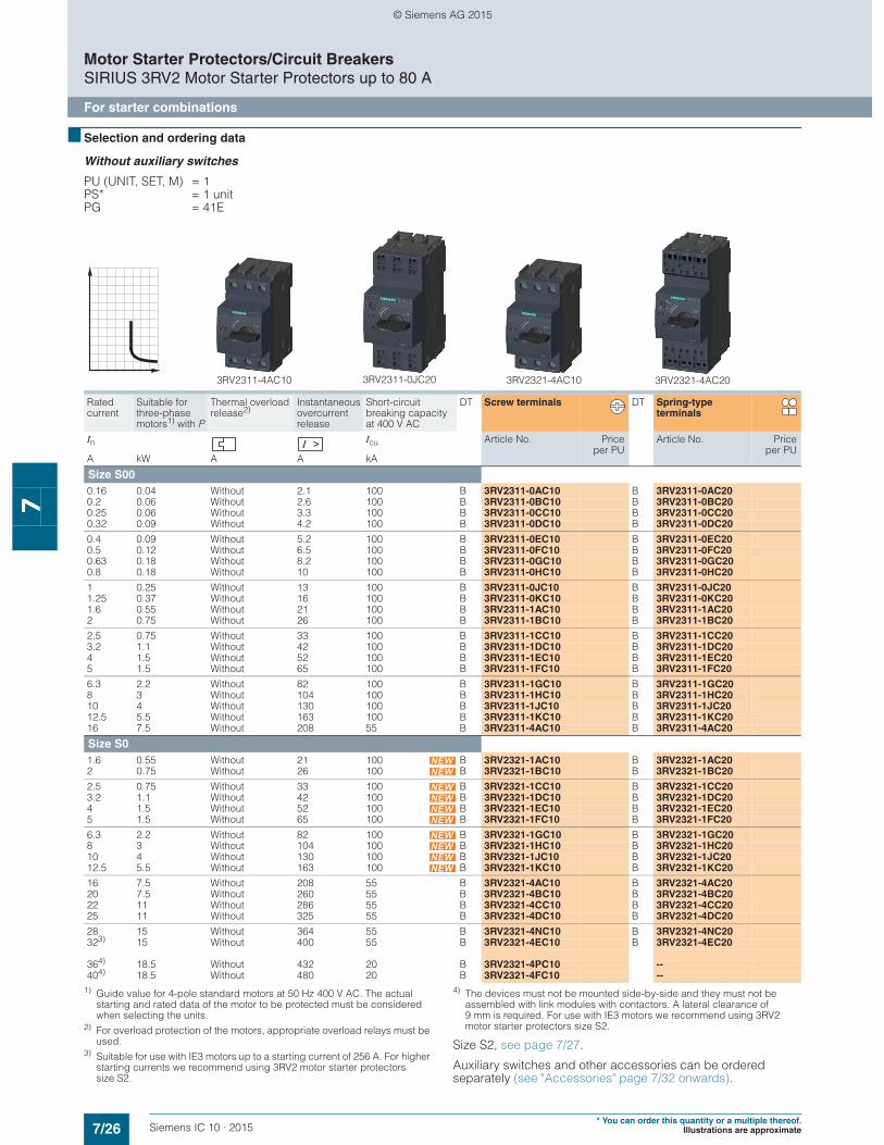
Without auxiliary switches
PU (UNIT, SET, M) = 1PS* = 1 unitPG = 41E
1) Guide value for 4-pole standard motors at 50 Hz 400 V AC. The actual starting and rated data of the motor to be protected must be considered when selecting the units.
2) For overload protection of the motors, appropriate overload relays must be used.
3) Suitable for use with IE3 motors up to a starting current of 256 A. For higher starting currents we recommend using 3RV2 motor starter protectors size S2.
4) The devices must not be mounted side-by-side and they must not be assembled with link modules with contactors. A lateral clearance of 9 mm is required. For use with IE3 motors we recommend using 3RV2 motor starter protectors size S2.
Size S2, see page 7/27.
Auxiliary switches and other accessories can be ordered separately (see "Accessories" page 7/32 onwards).
Rated current
Suitable for three-phase motors1) with P
Thermal overload release2)
Instantaneous overcurrent release
Short-circuit breaking capacity at 400 V AC
DT Screw terminals DT Spring-type terminals
In Icu Article No. Priceper PU
Article No. Priceper PU
A kW A A kA
Size S00 0.16 0.04 Without 2.1 100 B 3RV2311-0AC10 B 3RV2311-0AC200.2 0.06 Without 2.6 100 B 3RV2311-0BC10 B 3RV2311-0BC200.25 0.06 Without 3.3 100 B 3RV2311-0CC10 B 3RV2311-0CC200.32 0.09 Without 4.2 100 B 3RV2311-0DC10 B 3RV2311-0DC20
0.4 0.09 Without 5.2 100 B 3RV2311-0EC10 B 3RV2311-0EC200.5 0.12 Without 6.5 100 B 3RV2311-0FC10 B 3RV2311-0FC200.63 0.18 Without 8.2 100 B 3RV2311-0GC10 B 3RV2311-0GC200.8 0.18 Without 10 100 B 3RV2311-0HC10 B 3RV2311-0HC20
1 0.25 Without 13 100 B 3RV2311-0JC10 B 3RV2311-0JC201.25 0.37 Without 16 100 B 3RV2311-0KC10 B 3RV2311-0KC201.6 0.55 Without 21 100 B 3RV2311-1AC10 B 3RV2311-1AC202 0.75 Without 26 100 B 3RV2311-1BC10 B 3RV2311-1BC20
2.5 0.75 Without 33 100 B 3RV2311-1CC10 B 3RV2311-1CC203.2 1.1 Without 42 100 B 3RV2311-1DC10 B 3RV2311-1DC204 1.5 Without 52 100 B 3RV2311-1EC10 B 3RV2311-1EC205 1.5 Without 65 100 B 3RV2311-1FC10 B 3RV2311-1FC20
6.3 2.2 Without 82 100 B 3RV2311-1GC10 B 3RV2311-1GC208 3 Without 104 100 B 3RV2311-1HC10 B 3RV2311-1HC2010 4 Without 130 100 B 3RV2311-1JC10 B 3RV2311-1JC2012.5 5.5 Without 163 100 B 3RV2311-1KC10 B 3RV2311-1KC2016 7.5 Without 208 55 B 3RV2311-4AC10 B 3RV2311-4AC20
Size S0 1.6 0.55 Without 21 100 B 3RV2321-1AC10 B 3RV2321-1AC202 0.75 Without 26 100 B 3RV2321-1BC10 B 3RV2321-1BC20
2.5 0.75 Without 33 100 B 3RV2321-1CC10 B 3RV2321-1CC203.2 1.1 Without 42 100 B 3RV2321-1DC10 B 3RV2321-1DC204 1.5 Without 52 100 B 3RV2321-1EC10 B 3RV2321-1EC205 1.5 Without 65 100 B 3RV2321-1FC10 B 3RV2321-1FC20
6.3 2.2 Without 82 100 B 3RV2321-1GC10 B 3RV2321-1GC208 3 Without 104 100 B 3RV2321-1HC10 B 3RV2321-1HC2010 4 Without 130 100 B 3RV2321-1JC10 B 3RV2321-1JC2012.5 5.5 Without 163 100 B 3RV2321-1KC10 B 3RV2321-1KC20
16 7.5 Without 208 55 B 3RV2321-4AC10 B 3RV2321-4AC2020 7.5 Without 260 55 B 3RV2321-4BC10 B 3RV2321-4BC2022 11 Without 286 55 B 3RV2321-4CC10 B 3RV2321-4CC2025 11 Without 325 55 B 3RV2321-4DC10 B 3RV2321-4DC20
28 15 Without 364 55 B 3RV2321-4NC10 B 3RV2321-4NC20323) 15 Without 400 55 B 3RV2321-4EC10 B 3RV2321-4EC20
364) 18.5 Without 432 20 B 3RV2321-4PC10 --404) 18.5 Without 480 20 B 3RV2321-4FC10 --
3RV2321-4AC203RV2321-4AC103RV2311-4AC10 3RV2311-0JC20
© Siemens AG 2015
7/27Siemens IC 10 · 2015* You can order this quantity or a multiple thereof.Illustrations are approximate
Motor Starter Protectors/Circuit BreakersSIRIUS 3RV2 Motor Starter Protectors up to 80 A
For starter combinations
7
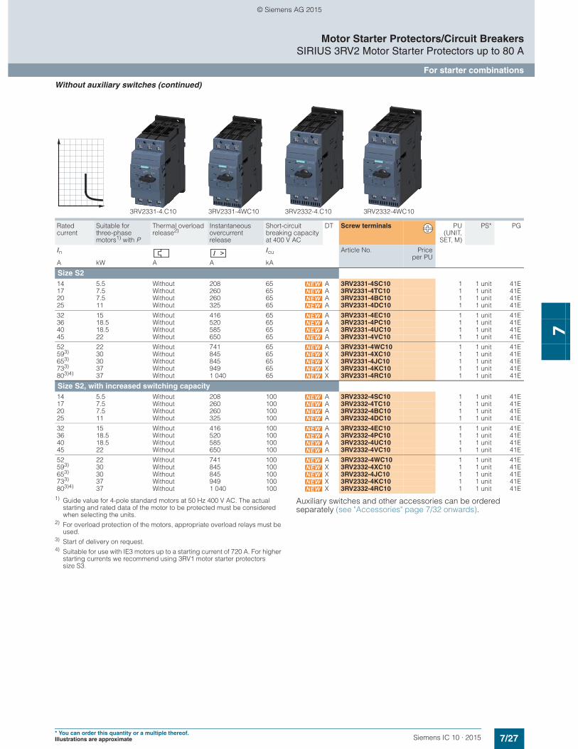
Without auxiliary switches (continued)
1) Guide value for 4-pole standard motors at 50 Hz 400 V AC. The actual starting and rated data of the motor to be protected must be considered when selecting the units.
2) For overload protection of the motors, appropriate overload relays must be used.
3) Start of delivery on request.4) Suitable for use with IE3 motors up to a starting current of 720 A. For higher
starting currents we recommend using 3RV1 motor starter protectors size S3.
Auxiliary switches and other accessories can be ordered separately (see "Accessories" page 7/32 onwards).
Rated current
Suitable for three-phase motors1) with P
Thermal overload release2)
Instantaneous overcurrent release
Short-circuit breaking capacity at 400 V AC
DT Screw terminals PU(UNIT,
SET, M)
PS* PG
In Icu Article No. Priceper PU
A kW A A kA
Size S214 5.5 Without 208 65 A 3RV2331-4SC10 1 1 unit 41E17 7.5 Without 260 65 A 3RV2331-4TC10 1 1 unit 41E20 7.5 Without 260 65 A 3RV2331-4BC10 1 1 unit 41E25 11 Without 325 65 A 3RV2331-4DC10 1 1 unit 41E
32 15 Without 416 65 A 3RV2331-4EC10 1 1 unit 41E36 18.5 Without 520 65 A 3RV2331-4PC10 1 1 unit 41E40 18.5 Without 585 65 A 3RV2331-4UC10 1 1 unit 41E45 22 Without 650 65 A 3RV2331-4VC10 1 1 unit 41E
52 22 Without 741 65 A 3RV2331-4WC10 1 1 unit 41E593) 30 Without 845 65 X 3RV2331-4XC10 1 1 unit 41E653) 30 Without 845 65 X 3RV2331-4JC10 1 1 unit 41E733) 37 Without 949 65 X 3RV2331-4KC10 1 1 unit 41E803)4) 37 Without 1 040 65 X 3RV2331-4RC10 1 1 unit 41E
Size S2, with increased switching capacity14 5.5 Without 208 100 A 3RV2332-4SC10 1 1 unit 41E17 7.5 Without 260 100 A 3RV2332-4TC10 1 1 unit 41E20 7.5 Without 260 100 A 3RV2332-4BC10 1 1 unit 41E25 11 Without 325 100 A 3RV2332-4DC10 1 1 unit 41E
32 15 Without 416 100 A 3RV2332-4EC10 1 1 unit 41E36 18.5 Without 520 100 A 3RV2332-4PC10 1 1 unit 41E40 18.5 Without 585 100 A 3RV2332-4UC10 1 1 unit 41E45 22 Without 650 100 A 3RV2332-4VC10 1 1 unit 41E
52 22 Without 741 100 A 3RV2332-4WC10 1 1 unit 41E593) 30 Without 845 100 X 3RV2332-4XC10 1 1 unit 41E653) 30 Without 845 100 X 3RV2332-4JC10 1 1 unit 41E733) 37 Without 949 100 X 3RV2332-4KC10 1 1 unit 41E803)4) 37 Without 1 040 100 X 3RV2332-4RC10 1 1 unit 41E
3RV2331-4WC103RV2331-4.C10 3RV2332-4WC103RV2332-4.C10
© Siemens AG 2015
7/28 Siemens IC 10 · 2015* You can order this quantity or a multiple thereof.
Illustrations are approximate
Motor Starter Protectors/Circuit BreakersSIRIUS 3RV2 Motor Starter Protectors up to 80 A
For transformer protection
7
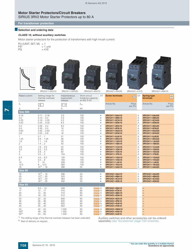
■ Selection and ordering data
CLASS 10, without auxiliary switches
Motor starter protectors for the protection of transformers with high inrush current
PU (UNIT, SET, M) = 1PS* = 1 unitPG = 41E
1) The setting range of the thermal overload releases has been extended.2) Start of delivery on request.
Auxiliary switches and other accessories can be ordered separately (see "Accessories" page 7/32 onwards).
Rated current Setting range for thermal overload release
Instantaneous overcurrent release
Short-circuit breaking capacity at 400 V AC
DT Screw terminals DT Spring-type terminals
In Icu Article No. Priceper PU
Article No. Priceper PU
A A A kA
Size S00 0.16 0.11 ... 0.16 3.3 100 } 3RV2411-0AA10 A 3RV2411-0AA200.2 0.14 ... 0.2 4.2 100 } 3RV2411-0BA10 A 3RV2411-0BA200.25 0.18 ... 0.25 5.2 100 } 3RV2411-0CA10 A 3RV2411-0CA200.32 0.22 ... 0.32 6.5 100 } 3RV2411-0DA10 A 3RV2411-0DA20
0.4 0.28 ... 0.4 8.2 100 } 3RV2411-0EA10 A 3RV2411-0EA200.5 0.35 ... 0.5 10 100 } 3RV2411-0FA10 A 3RV2411-0FA200.63 0.45 ... 0.63 13 100 } 3RV2411-0GA10 A 3RV2411-0GA200.8 0.55 ... 0.8 16 100 } 3RV2411-0HA10 A 3RV2411-0HA20
1 0.7 ... 1 21 100 } 3RV2411-0JA10 A 3RV2411-0JA201.25 0.9 ... 1.25 26 100 } 3RV2411-0KA10 A 3RV2411-0KA201.6 1.1 ... 1.6 33 100 } 3RV2411-1AA10 A 3RV2411-1AA202 1.4 ... 2 42 100 } 3RV2411-1BA10 A 3RV2411-1BA20
2.5 1.8 ... 2.5 52 100 } 3RV2411-1CA10 A 3RV2411-1CA203.2 2.2 ... 3.2 65 100 } 3RV2411-1DA10 A 3RV2411-1DA204 2.8 ... 4 82 100 } 3RV2411-1EA10 A 3RV2411-1EA205 3.5 ... 5 104 100 } 3RV2411-1FA10 A 3RV2411-1FA20
6.3 4.5 ... 6.3 130 100 } 3RV2411-1GA10 A 3RV2411-1GA208 5.5 ... 8 163 100 } 3RV2411-1HA10 A 3RV2411-1HA2010 7 ... 10 208 100 } 3RV2411-1JA10 A 3RV2411-1JA2012.5 9 ... 12.5 260 100 } 3RV2411-1KA10 A 3RV2411-1KA2016 101) ... 16 286 55 } 3RV2411-4AA10 A 3RV2411-4AA20
Size S0 16 101) ... 16 286 55 } 3RV2421-4AA10 A 3RV2421-4AA2020 131) ... 20 325 55 } 3RV2421-4BA10 A 3RV2421-4BA2022 161) ... 22 364 55 } 3RV2421-4CA10 A 3RV2421-4CA2025 181) ... 25 400 55 } 3RV2421-4DA10 A 3RV2421-4DA20
Size S2 14 9.5 ... 14 328 65 A 3RV2431-4SA10 --17 12 ... 17 410 65 A 3RV2431-4TA10 --20 14 ... 20 410 65 A 3RV2431-4BA10 --25 18 ... 25 512 65 A 3RV2431-4DA10 --
32 22 ... 32 656 65 A 3RV2431-4EA10 --36 28 ... 36 820 65 A 3RV2431-4PA10 --40 32 ... 40 820 65 A 3RV2431-4UA10 --45 35 ... 45 922 65 A 3RV2431-4VA10 --
52 42 ... 52 1 025 65 A 3RV2431-4WA10 --592) 49 ... 59 1 332 65 X 3RV2431-4XA10 --652) 54 ... 65 1 332 65 X 3RV2431-4JA10 --
3RV2411-0AA10 3RV2411-0AA20 3RV2421-4AA10 3RV2421-4AA20 3RV2431-4.A10 3RV2421-4WA10
© Siemens AG 2015

7/29Siemens IC 10 · 2015* You can order this quantity or a multiple thereof.Illustrations are approximate
Motor Starter Protectors/Circuit BreakersSIRIUS 3RV2 Circuit Breakers up to 80 A
For system protection according to UL 489/CSA C22.2 No. 5
7
■ Selection and ordering data
Without auxiliary switches
Circuit breakers for system protection and non-motor loads according to UL/CSA
1) Rated value 100 % according to UL 489 and IEC 60947-2 ("100 % rated breaker").
2) Values for 600 Y/347 V AC, see page 7/15.
Lateral and transverse auxiliary switches can be ordered separately (see "Accessories" from page 7/32 onwards).
Rated current1) Thermal overload releases (non-adjustable)
Instantaneous overcurrent release
Short-circuit breaking capacity at 480 Y/277 V AC2)
DT Screw terminals PU(UNIT,
SET, M)
PS* PG
In1) Ibc Article No. Price
per PUA A A kA
Size S000.16 0.16 2.1 65 B 3RV2711-0AD10 1 1 unit 41E0.2 0.2 2.6 65 B 3RV2711-0BD10 1 1 unit 41E0.25 0.25 3.3 65 B 3RV2711-0CD10 1 1 unit 41E0.32 0.32 4.2 65 B 3RV2711-0DD10 1 1 unit 41E
0.4 0.4 5.2 65 B 3RV2711-0ED10 1 1 unit 41E0.5 0.5 6.5 65 B 3RV2711-0FD10 1 1 unit 41E0.63 0.63 8.2 65 B 3RV2711-0GD10 1 1 unit 41E0.8 0.8 10 65 B 3RV2711-0HD10 1 1 unit 41E
1 1 13 65 B 3RV2711-0JD10 1 1 unit 41E1.25 1.25 16 65 B 3RV2711-0KD10 1 1 unit 41E1.6 1.6 21 65 B 3RV2711-1AD10 1 1 unit 41E2 2 26 65 B 3RV2711-1BD10 1 1 unit 41E
2.5 2.5 33 65 B 3RV2711-1CD10 1 1 unit 41E3.2 3.2 42 65 B 3RV2711-1DD10 1 1 unit 41E4 4 52 65 B 3RV2711-1ED10 1 1 unit 41E5 5 65 65 B 3RV2711-1FD10 1 1 unit 41E
6.3 6.3 82 65 B 3RV2711-1GD10 1 1 unit 41E8 8 104 65 B 3RV2711-1HD10 1 1 unit 41E10 10 130 65 B 3RV2711-1JD10 1 1 unit 41E12.5 12.5 163 65 B 3RV2711-1KD10 1 1 unit 41E15 15 208 65 B 3RV2711-4AD10 1 1 unit 41E
Size S020 20 260 50 B 3RV2721-4BD10 1 1 unit 41E22 22 286 50 B 3RV2721-4CD10 1 1 unit 41E
3RV2711-0AD10
© Siemens AG 2015
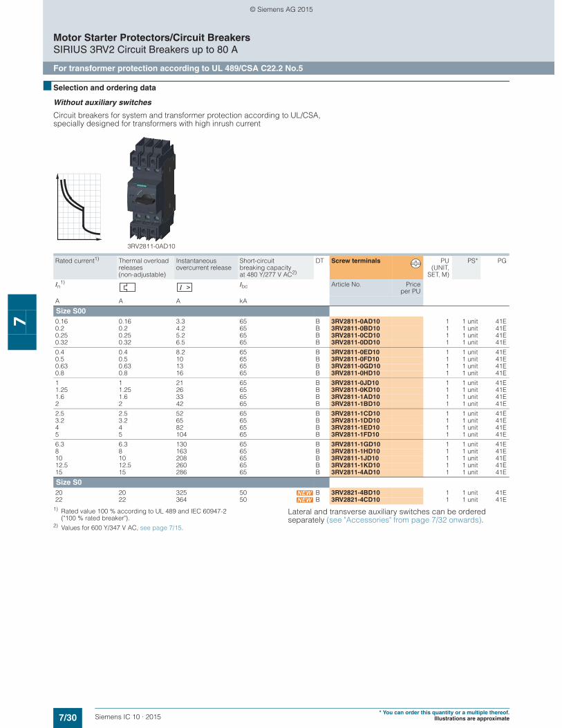
7/30 Siemens IC 10 · 2015* You can order this quantity or a multiple thereof.
Illustrations are approximate
Motor Starter Protectors/Circuit BreakersSIRIUS 3RV2 Circuit Breakers up to 80 A
For transformer protection according to UL 489/CSA C22.2 No.5
7
■ Selection and ordering data
Without auxiliary switches
Circuit breakers for system and transformer protection according to UL/CSA, specially designed for transformers with high inrush current
1) Rated value 100 % according to UL 489 and IEC 60947-2 ("100 % rated breaker").
2) Values for 600 Y/347 V AC, see page 7/15.
Lateral and transverse auxiliary switches can be ordered separately (see "Accessories" from page 7/32 onwards).
Rated current1) Thermal overload releases (non-adjustable)
Instantaneous overcurrent release
Short-circuit breaking capacity at 480 Y/277 V AC2)
DT Screw terminals PU(UNIT,
SET, M)
PS* PG
In1) Ibc Article No. Price
per PU
A A A kA
Size S000.16 0.16 3.3 65 B 3RV2811-0AD10 1 1 unit 41E0.2 0.2 4.2 65 B 3RV2811-0BD10 1 1 unit 41E0.25 0.25 5.2 65 B 3RV2811-0CD10 1 1 unit 41E0.32 0.32 6.5 65 B 3RV2811-0DD10 1 1 unit 41E
0.4 0.4 8.2 65 B 3RV2811-0ED10 1 1 unit 41E0.5 0.5 10 65 B 3RV2811-0FD10 1 1 unit 41E0.63 0.63 13 65 B 3RV2811-0GD10 1 1 unit 41E0.8 0.8 16 65 B 3RV2811-0HD10 1 1 unit 41E
1 1 21 65 B 3RV2811-0JD10 1 1 unit 41E1.25 1.25 26 65 B 3RV2811-0KD10 1 1 unit 41E1.6 1.6 33 65 B 3RV2811-1AD10 1 1 unit 41E2 2 42 65 B 3RV2811-1BD10 1 1 unit 41E
2.5 2.5 52 65 B 3RV2811-1CD10 1 1 unit 41E3.2 3.2 65 65 B 3RV2811-1DD10 1 1 unit 41E4 4 82 65 B 3RV2811-1ED10 1 1 unit 41E5 5 104 65 B 3RV2811-1FD10 1 1 unit 41E
6.3 6.3 130 65 B 3RV2811-1GD10 1 1 unit 41E8 8 163 65 B 3RV2811-1HD10 1 1 unit 41E10 10 208 65 B 3RV2811-1JD10 1 1 unit 41E12.5 12.5 260 65 B 3RV2811-1KD10 1 1 unit 41E15 15 286 65 B 3RV2811-4AD10 1 1 unit 41E
Size S020 20 325 50 B 3RV2821-4BD10 1 1 unit 41E22 22 364 50 B 3RV2821-4CD10 1 1 unit 41E
3RV2811-0AD10
© Siemens AG 2015
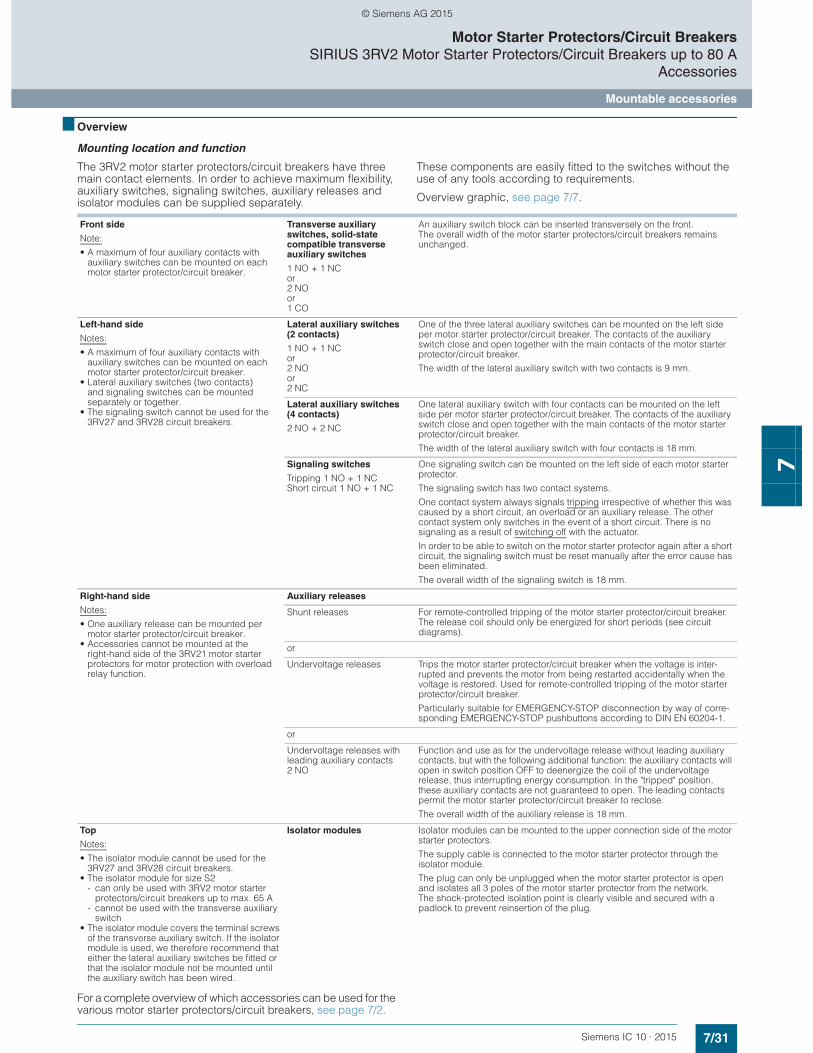
7/31Siemens IC 10 · 2015
Motor Starter Protectors/Circuit BreakersSIRIUS 3RV2 Motor Starter Protectors/Circuit Breakers up to 80 A
Accessories
Mountable accessories
7
■ Overview
Mounting location and function
The 3RV2 motor starter protectors/circuit breakers have three main contact elements. In order to achieve maximum flexibility, auxiliary switches, signaling switches, auxiliary releases and isolator modules can be supplied separately.
These components are easily fitted to the switches without the use of any tools according to requirements.
Overview graphic, see page 7/7.
For a complete overview of which accessories can be used for the various motor starter protectors/circuit breakers, see page 7/2.
Front side
Note:
• A maximum of four auxiliary contacts with auxiliary switches can be mounted on each motor starter protector/circuit breaker.
Transverse auxiliary switches, solid-state compatible transverse auxiliary switches
1 NO + 1 NCor2 NOor 1 CO
An auxiliary switch block can be inserted transversely on the front. The overall width of the motor starter protectors/circuit breakers remains unchanged.
Left-hand side
Notes:
• A maximum of four auxiliary contacts with auxiliary switches can be mounted on each motor starter protector/circuit breaker.
• Lateral auxiliary switches (two contacts) and signaling switches can be mounted separately or together.
• The signaling switch cannot be used for the 3RV27 and 3RV28 circuit breakers.
Lateral auxiliary switches (2 contacts)
1 NO + 1 NCor2 NOor 2 NC
One of the three lateral auxiliary switches can be mounted on the left side per motor starter protector/circuit breaker. The contacts of the auxiliary switch close and open together with the main contacts of the motor starter protector/circuit breaker.
The width of the lateral auxiliary switch with two contacts is 9 mm.
Lateral auxiliary switches (4 contacts)
2 NO + 2 NC
One lateral auxiliary switch with four contacts can be mounted on the left side per motor starter protector/circuit breaker. The contacts of the auxiliary switch close and open together with the main contacts of the motor starter protector/circuit breaker.
The width of the lateral auxiliary switch with four contacts is 18 mm.
Signaling switches
Tripping 1 NO + 1 NCShort circuit 1 NO + 1 NC
One signaling switch can be mounted on the left side of each motor starter protector.
The signaling switch has two contact systems.
One contact system always signals tripping irrespective of whether this was caused by a short circuit, an overload or an auxiliary release. The other contact system only switches in the event of a short circuit. There is no signaling as a result of switching off with the actuator.
In order to be able to switch on the motor starter protector again after a short circuit, the signaling switch must be reset manually after the error cause has been eliminated.
The overall width of the signaling switch is 18 mm.
Right-hand side
Notes:
• One auxiliary release can be mounted per motor starter protector/circuit breaker.
• Accessories cannot be mounted at the right-hand side of the 3RV21 motor starter protectors for motor protection with overload relay function.
Auxiliary releases
Shunt releases For remote-controlled tripping of the motor starter protector/circuit breaker. The release coil should only be energized for short periods (see circuit diagrams).
or
Undervoltage releases Trips the motor starter protector/circuit breaker when the voltage is inter-rupted and prevents the motor from being restarted accidentally when the voltage is restored. Used for remote-controlled tripping of the motor starter protector/circuit breaker.
Particularly suitable for EMERGENCY-STOP disconnection by way of corre-sponding EMERGENCY-STOP pushbuttons according to DIN EN 60204-1.
or
Undervoltage releases with leading auxiliary contacts 2 NO
Function and use as for the undervoltage release without leading auxiliary contacts, but with the following additional function: the auxiliary contacts will open in switch position OFF to deenergize the coil of the undervoltage release, thus interrupting energy consumption. In the "tripped" position, these auxiliary contacts are not guaranteed to open. The leading contacts permit the motor starter protector/circuit breaker to reclose.
The overall width of the auxiliary release is 18 mm.
Top
Notes:
• The isolator module cannot be used for the 3RV27 and 3RV28 circuit breakers.
• The isolator module for size S2- can only be used with 3RV2 motor starter
protectors/circuit breakers up to max. 65 A- cannot be used with the transverse auxiliary
switch• The isolator module covers the terminal screws
of the transverse auxiliary switch. If the isolator module is used, we therefore recommend that either the lateral auxiliary switches be fitted or that the isolator module not be mounted until the auxiliary switch has been wired.
Isolator modules Isolator modules can be mounted to the upper connection side of the motor starter protectors.
The supply cable is connected to the motor starter protector through the isolator module.
The plug can only be unplugged when the motor starter protector is open and isolates all 3 poles of the motor starter protector from the network. The shock-protected isolation point is clearly visible and secured with a padlock to prevent reinsertion of the plug.
© Siemens AG 2015

7/32 Siemens IC 10 · 2015* You can order this quantity or a multiple thereof.
Illustrations are approximate
Motor Starter Protectors/Circuit BreakersSIRIUS 3RV2 Motor Starter Protectors/Circuit Breakers up to 80 AAccessories
Mountable accessories
7
■ Selection and ordering data
PU (UNIT, SET, M) = 1PS* = 1 unit (unless otherwise specified)PG = 41E
1) Each motor starter protector/circuit breaker can be fitted with one trans-verse and one lateral auxiliary switch. The lateral auxiliary switch with 2 NO + 2 NC is used without a transverse auxiliary switch.
2) The 3RV29 auxiliary and signaling switches with 1 NO + 1 NC are also available with ring terminal lug connection. The Article No. must be changed in the 8th digit to "4": e.g. 3RV2901-4E.
3) This accessory cannot be used for the 3RV27 and 3RV28 circuit breakers.4) The isolator module for size S2 can be used only with 3RV2 motor starter
protectors/circuit breakers up to max. 65 A. Similarly, it cannot be used with the transverse auxiliary switch.
Version For motor starter protectors/circuit breakers
DT Screw terminals DT Spring-type terminals
Article No. Priceper PU
Article No. Priceper PUSize
Auxiliary switches1)
3RV2901-1E
3RV2901-2E
3RV2901-1G
Transverse auxiliary switches For front mounting
1 CO S00 ... S2 } 3RV2901-1D --1 NO + 1 NC2)
} 3RV2901-1E } 3RV2901-2E2 NO } 3RV2901-1F } 3RV2901-2F
Electronic compatible transverse auxiliary switches Mountable on the front,for operation in dusty atmosphere and in electronic circuits with low operating currents
1 CO S00 ... S2 A 3RV2901-1G --
3RV2901-0H
Covers for transverse auxiliary switches(PKG* = 10 units)
S00 ... S2 } 3RV2901-0H --
3RV2901-1A 3RV2901-2A
Lateral auxiliary switches Mountable on the left
1 NO + 1 NC2) S00 ... S2 } 3RV2901-1A } 3RV2901-2A2 NO } 3RV2901-1B } 3RV2901-2B2 NC } 3RV2901-1C } 3RV2901-2C2 NO + 2 NC A 3RV2901-1J --
Signaling switches3)
3RV2921-1M 3RV2921-2M
Signaling switches2)
One signaling switch can be mounted on the left per motor starter protector.
Separate tripped and short-circuit alarms, 1 NO + 1 NC each
S00 ... S2 } 3RV2921-1M } 3RV2921-2M
Isolator modules3)
3RV2928-1A 3RV2938-1A
Isolator modules4)
Visible isolating distance for isolating individual motor starter protectors from the network, lockable in disconnected position
S00, S0 } 3RV2928-1A --
S24) A 3RV2938-1A --
© Siemens AG 2015
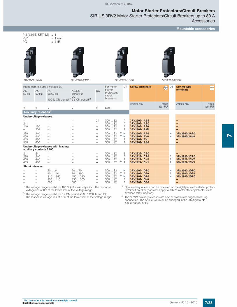
7/33Siemens IC 10 · 2015* You can order this quantity or a multiple thereof.Illustrations are approximate
Motor Starter Protectors/Circuit BreakersSIRIUS 3RV2 Motor Starter Protectors/Circuit Breakers up to 80 A
Accessories
Mountable accessories
7
PU (UNIT, SET, M) = 1PS* = 1 unitPG = 41E
1) The voltage range is valid for 100 % (infinite) ON period. The response voltage lies at 0.9 of the lower limit of the voltage range.
2) The voltage range is valid for 5 s ON period at AC 50/60Hz and DC. The response voltage lies at 0.85 of the lower limit of the voltage range.
3) One auxiliary release can be mounted on the right per motor starter protec-tor/circuit breaker (does not apply to 3RV21 motor starter protectors with overload relay function).
4) The 3RV29 auxiliary releases are also available with ring terminal lug connection. The Article No. must be changed in the 8th digit to "4":e.g. 3RV2902-4AP0.
Rated control supply voltage Us For motor starter protectors/circuit breakers
DT Screw terminals DT Spring-type terminalsAC AC AC AC/DC DC
50 Hz 60 Hz 50/60 Hz
100 % ON period1)
50/60 Hz, DC 5 s ON period2)
Article No. Priceper PU
Article No. Priceper PUV V V V V Size
Auxiliary releases3) Undervoltage releases
-- -- -- -- 24 S00 ... S2 A 3RV2902-1AB4 --24 -- -- -- -- S00 ... S2 A 3RV2902-1AB0 --110 120 -- -- -- S00 ... S2 A 3RV2902-1AF0 ---- 208 -- -- -- S00 ... S2 A 3RV2902-1AM1 --
230 240 -- -- -- S00 ... S2 4)} 3RV2902-1AP0 } 3RV2902-2AP0
400 440 -- -- -- S00 ... S2 4)} 3RV2902-1AV0 } 3RV2902-2AV0
415 480 -- -- -- S00 ... S2 A 3RV2902-1AV1 --500 600 -- -- -- S00 ... S2 A 3RV2902-1AS0 --
Undervoltage releases with leading auxiliary contacts 2 NO
24 24 -- -- -- S00 ... S2 B 3RV2922-1CB0 --230 240 -- -- -- S00 ... S2 A 3RV2922-1CP0 A 3RV2922-2CP0400 440 -- -- -- S00 ... S2 A 3RV2922-1CV0 A 3RV2922-2CV0415 480 -- -- -- S00 ... S2 4) A 3RV2922-1CV1 A 3RV2922-2CV1
Shunt releases
-- -- 20 ... 24 20 ... 70 -- S00 ... S2 } 3RV2902-1DB0 } 3RV2902-2DB0-- -- 90 ... 110 70 ... 190 -- S00 ... S2 4) A 3RV2902-1DF0 A 3RV2902-2DF0-- -- 210 ... 240 190 ... 330 -- S00 ... S2 4)
} 3RV2902-1DP0 } 3RV2902-2DP0-- -- 350 ... 415 330 ... 500 -- S00 ... S2 A 3RV2902-1DV0 ---- -- 500 500 -- S00 ... S2 A 3RV2902-1DS0 --
3RV2902-1AV0 3RV2902-2AV0 3RV2922-1CP0 3RV2902-2DB0
© Siemens AG 2015
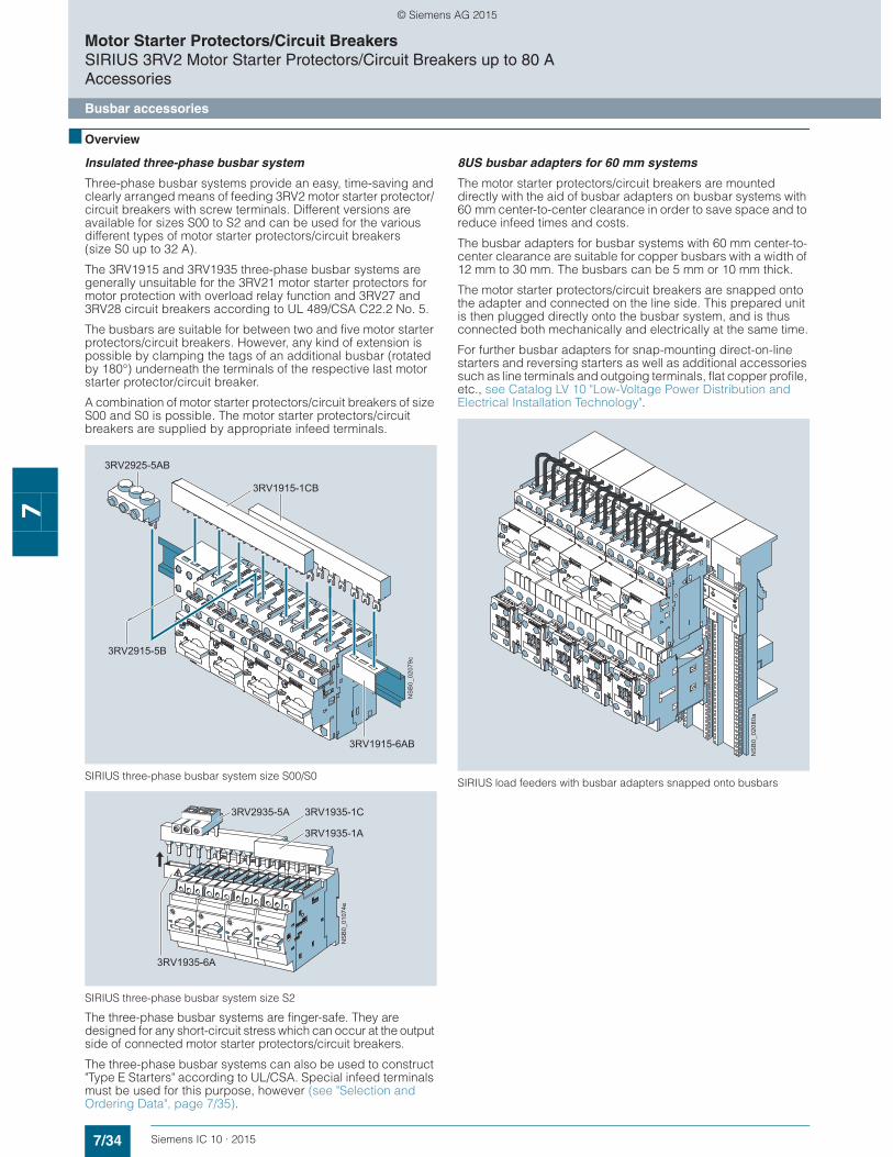
7/34 Siemens IC 10 · 2015
Motor Starter Protectors/Circuit BreakersSIRIUS 3RV2 Motor Starter Protectors/Circuit Breakers up to 80 AAccessories
Busbar accessories
7
■ Overview
Insulated three-phase busbar system
Three-phase busbar systems provide an easy, time-saving and clearly arranged means of feeding 3RV2 motor starter protector/ circuit breakers with screw terminals. Different versions are available for sizes S00 to S2 and can be used for the various different types of motor starter protectors/circuit breakers(size S0 up to 32 A).
The 3RV1915 and 3RV1935 three-phase busbar systems are generally unsuitable for the 3RV21 motor starter protectors for motor protection with overload relay function and 3RV27 and 3RV28 circuit breakers according to UL 489/CSA C22.2 No. 5.
The busbars are suitable for between two and five motor starter protectors/circuit breakers. However, any kind of extension is possible by clamping the tags of an additional busbar (rotated by 180°) underneath the terminals of the respective last motor starter protector/circuit breaker.
A combination of motor starter protectors/circuit breakers of size S00 and S0 is possible. The motor starter protectors/circuit breakers are supplied by appropriate infeed terminals.
SIRIUS three-phase busbar system size S00/S0
SIRIUS three-phase busbar system size S2
The three-phase busbar systems are finger-safe. They are designed for any short-circuit stress which can occur at the output side of connected motor starter protectors/circuit breakers.
The three-phase busbar systems can also be used to construct "Type E Starters" according to UL/CSA. Special infeed terminals must be used for this purpose, however (see "Selection and Ordering Data", page 7/35).
8US busbar adapters for 60 mm systems
The motor starter protectors/circuit breakers are mounted directly with the aid of busbar adapters on busbar systems with 60 mm center-to-center clearance in order to save space and to reduce infeed times and costs.
The busbar adapters for busbar systems with 60 mm center-to-center clearance are suitable for copper busbars with a width of 12 mm to 30 mm. The busbars can be 5 mm or 10 mm thick.
The motor starter protectors/circuit breakers are snapped onto the adapter and connected on the line side. This prepared unit is then plugged directly onto the busbar system, and is thus connected both mechanically and electrically at the same time.
For further busbar adapters for snap-mounting direct-on-line starters and reversing starters as well as additional accessories such as line terminals and outgoing terminals, flat copper profile, etc., see Catalog LV 10 "Low-Voltage Power Distribution and Electrical Installation Technology".
SIRIUS load feeders with busbar adapters snapped onto busbars
NS
B0_
0207
9c
3RV1915-6AB
3RV2915-5B
3RV2925-5AB
3RV1915-1CB
3RV2935-5A
3RV1935-6A
3RV1935-1A
NS
B0_
0107
4e
3RV1935-1C
NS
B0_
0208
0a
© Siemens AG 2015
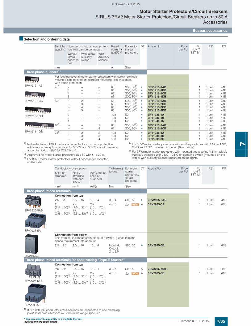
7/35Siemens IC 10 · 2015* You can order this quantity or a multiple thereof.Illustrations are approximate
Motor Starter Protectors/Circuit BreakersSIRIUS 3RV2 Motor Starter Protectors/Circuit Breakers up to 80 A
Accessories
Busbar accessories
7
■ Selection and ordering data
1) Not suitable for 3RV21 motor starter protectors for motor protection with overload relay function and for 3RV27 and 3RV28 circuit breakers according to UL 489/CSA C22.2 No. 5.
2) Approved for motor starter protectors size S0 with In ≤ 32 A.3) For 3RV2 motor starter protectors without accessories mounted
on the side.
4) For 3RV2 motor starter protectors with auxiliary switches with 1 NO + 1 NC, 2 NO and 2 NC mounted on the left (9 mm wide).
5) For 3RV2 motor starter protectors with mounted accessories (18 mm wide). Auxiliary switches with 2 NO + 2 NC or signaling switch (mounted on the left) or with auxiliary release (mounted on the right).
1) If two different conductor cross-sections are connected to one clamping point, both cross-sections must be in the range specified.
Modular spacing
Number of motor starter protec-tors that can be connected
Rated current In at 690 V
For motor starter protectors
DT Article No. Priceper PU
PU(UNIT,
SET, M)
PS* PG
Without lateral accesso-ries
With lateral auxiliary switch
With auxiliary release
mm A Size
Three-phase busbars1)
3RV1915-1AB
3RV1915-1BB
3RV1915-1CB
3RV1915-1DB
For feeding several motor starter protectors with screw terminals, mounted side by side on standard mounting rails, insulated, with touch protection
453) 2 -- -- 63 S00, S02)} 3RV1915-1AB 1 1 unit 41E
3 -- -- 63 S00, S02)} 3RV1915-1BB 1 1 unit 41E
4 -- -- 63 S00, S02)} 3RV1915-1CB 1 1 unit 41E
5 -- -- 63 S00, S02)} 3RV1915-1DB 1 1 unit 41E
554) -- 2 -- 63 S00, S02)} 3RV1915-2AB 1 1 unit 41E
-- 3 -- 63 S00, S02)} 3RV1915-2BB 1 1 unit 41E
-- 4 -- 63 S00, S02)} 3RV1915-2CB 1 1 unit 41E
-- 5 -- 63 S00, S02)} 3RV1915-2DB 1 1 unit 41E
2 -- -- 108 S2 } 3RV1935-1A 1 1 unit 41E3 -- -- 108 S2 } 3RV1935-1B 1 1 unit 41E4 -- -- 108 S2 } 3RV1935-1C 1 1 unit 41E
635) -- -- 2 63 S00, S02)} 3RV1915-3AB 1 1 unit 41E
-- -- 4 63 S00, S02)} 3RV1915-3CB 1 1 unit 41E
755) -- 2 2 108 S2 } 3RV1935-3A 1 1 unit 41E-- 3 3 108 S2 } 3RV1935-3B 1 1 unit 41E-- 4 4 108 S2 } 3RV1935-3C 1 1 unit 41E
Conductor cross-section Tightening torque
For motor starter protectors/circuit breakers
DT Article No. Priceper PU
PU(UNIT,
SET, M)
PS* PG
Solid or stranded
Finely stranded with end sleeve
AWG cables, solid or stranded
mm² mm² AWG Nm Size
Three-phase infeed terminals
3RV2925-5AB
3RV2935-5A
Connection from top
2.5 ... 25 2.5 ... 16 10 ... 4 3 ... 4 S00, S0 } 3RV2925-5AB 1 1 unit 41E
2 x (2.5 ... 50)1), 1 x (2.5 ... 70)1)
2 x (2.5 ... 35)1), 1 x (2.5 ... 50)1)
2 x(10 ... 1/0)1), 1 x (10 ... 2/0)1)
4 ... 6 S2 A 3RV2935-5A 1 1 unit 41E
3RV2915-5B
Connection from belowThis terminal is connected in place of a switch, please take the space requirement into account.
2.5 ... 25 2.5 ... 16 10 ... 4 Input: 4, Output: 2 ... 2.5
S00, S0 } 3RV2915-5B 1 1 unit 41E
Three-phase infeed terminals for constructing "Type E Starters"
3RV2925-5EB
3RV2935-5E
Connection from top
2.5 ... 25 2.5 ... 16 10 ... 4 3 ... 4 S00, S0 A 3RV2925-5EB 1 1 unit 41E
2 x (2.5 ... 50)1), 1 x (2.5 ... 70)1)
2 x (2.5 ... 35)1), 1 x (2.5 ... 50)1)
2 x(10 ... 1/0)1), 1 x (10 ... 2/0)1)
4 ... 6 S2 A 3RV2935-5E 1 1 unit 41E
© Siemens AG 2015
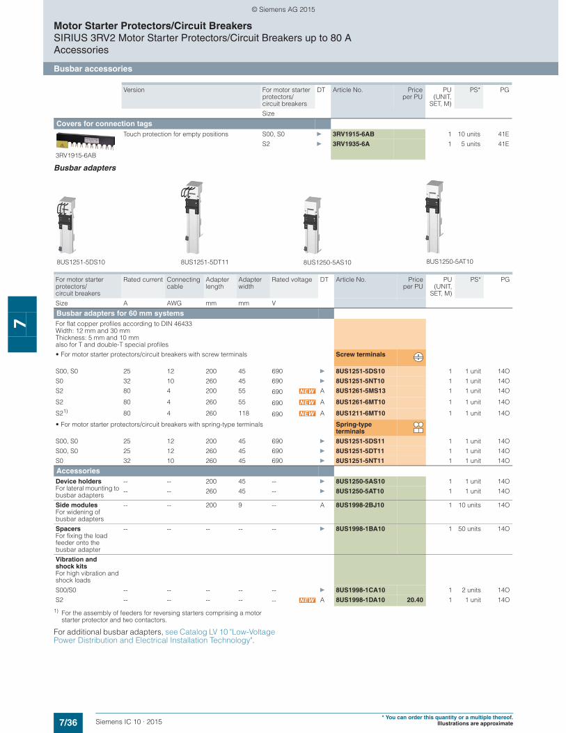
7/36 Siemens IC 10 · 2015* You can order this quantity or a multiple thereof.
Illustrations are approximate
Motor Starter Protectors/Circuit BreakersSIRIUS 3RV2 Motor Starter Protectors/Circuit Breakers up to 80 AAccessories
Busbar accessories
7
Busbar adapters
1) For the assembly of feeders for reversing starters comprising a motor starter protector and two contactors.
For additional busbar adapters, see Catalog LV 10 "Low-Voltage Power Distribution and Electrical Installation Technology".
Version For motor starter protectors/circuit breakers
DT Article No. Priceper PU
PU(UNIT,
SET, M)
PS* PG
Size
Covers for connection tags
3RV1915-6AB
Touch protection for empty positions S00, S0 } 3RV1915-6AB 1 10 units 41E
S2 } 3RV1935-6A 1 5 units 41E
For motor starter protectors/circuit breakers
Rated current Connecting cable
Adapter length
Adapter width
Rated voltage DT Article No. Priceper PU
PU(UNIT,
SET, M)
PS* PG
Size A AWG mm mm V
Busbar adapters for 60 mm systemsFor flat copper profiles according to DIN 46433 Width: 12 mm and 30 mm Thickness: 5 mm and 10 mm also for T and double-T special profiles
• For motor starter protectors/circuit breakers with screw terminals Screw terminals
S00, S0 25 12 200 45 690 } 8US1251-5DS10 1 1 unit 14O
S0 32 10 260 45 690 } 8US1251-5NT10 1 1 unit 14O
S2 80 4 200 55 690 A 8US1261-5MS13 1 1 unit 14O
S2 80 4 260 55 690 A 8US1261-6MT10 1 1 unit 14O
S21) 80 4 260 118 690 A 8US1211-6MT10 1 1 unit 14O
• For motor starter protectors/circuit breakers with spring-type terminals Spring-type terminals
S00, S0 25 12 200 45 690 } 8US1251-5DS11 1 1 unit 14O
S00, S0 25 12 260 45 690 } 8US1251-5DT11 1 1 unit 14O
S0 32 10 260 45 690 } 8US1251-5NT11 1 1 unit 14O
AccessoriesDevice holdersFor lateral mounting to busbar adapters
-- -- 200 45 -- } 8US1250-5AS10 1 1 unit 14O
-- -- 260 45 -- } 8US1250-5AT10 1 1 unit 14O
Side modules For widening of busbar adapters
-- -- 200 9 -- A 8US1998-2BJ10 1 10 units 14O
SpacersFor fixing the load feeder onto the busbar adapter
-- -- -- -- -- } 8US1998-1BA10 1 50 units 14O
Vibration and shock kitsFor high vibration and shock loads
S00/S0 -- -- -- -- -- } 8US1998-1CA10 1 2 units 14O
S2 -- -- -- -- -- A 8US1998-1DA10 20.40 1 1 unit 14O
8US1251-5DT11 8US1250-5AS10 8US1250-5AT108US1251-5DS10
© Siemens AG 2015

7/37Siemens IC 10 · 2015* You can order this quantity or a multiple thereof.Illustrations are approximate
Motor Starter Protectors/Circuit BreakersSIRIUS 3RV2 Motor Starter Protectors/Circuit Breakers up to 80 A
Accessories
Rotary operating mechanisms
7
■ Overview
Door-coupling rotary operating mechanisms
Motor starter protectors/circuit breakers with a rotary operating mechanism can be mounted in a control cabinet and operated externally by means of a door-coupling rotary operating mecha-nism. When the cabinet door with motor starter protector/circuit breaker is closed, the operating mechanism is coupled. When the motor starter protector/circuit breaker closes, the coupling is locked which prevents the door from being opened unintention-ally. This interlock can be defeated by the maintenance person-nel. In the OPEN position, the rotary operating mechanism can be secured against reclosing with up to three padlocks. Inadver-tent opening of the door is not possible in this case either.
SIRIUS 3RV2926-0K door-coupling rotary operating mechanism
SIRIUS 3RV2926-2B door-coupling rotary operating mechanisms for arduous conditions
■ Selection and ordering data
NS
B0_
0107
8a
NS
B0_
0107
9b
Version Color of handle
Version of extension shaft
For motor starter protectors/circuit breakers
DT Article No. Priceper PU
PU(UNIT,
SET, M)
PS* PG
mm Size
Door-coupling rotary operating mechanisms
3RV2926-0B
The door-coupling rotary operating mechanisms consist of a knob, a coupling driver and a 130/330 mm long extension shaft (6 mm x 6 mm).The door-coupling rotary operating mechanisms are designed to degree of protection IP64. The door locking device prevents accidental opening of the control cabinet door in the ON position of the motor starter protector/circuit breaker. The OFF position can be locked with up to three padlocks.
Door-coupling rotary operating mechanisms
Black 130 S00 ... S2 } 3RV2926-0B 1 1 unit 41E330 S00 ... S2 } 3RV2926-0K 1 1 unit 41E
EMERGENCY-STOP door-coupling rotary operating mechanisms
Red/yellow 130 S00 ... S2 } 3RV2926-0C 1 1 unit 41E330 S00 ... S2 } 3RV2926-0L 1 1 unit 41E
Door-coupling rotary operating mechanisms for arduous conditions
3RV2926-2B
3RV2936-2C
The door-coupling rotary operating mechanisms consist of a knob, a coupling driver, an extension shaft of 300 mm in length (8 mm x 8 mm), a spacer and two metal brackets, into which the motor starter protector/circuit breaker is inserted.
The door-coupling rotary operating mechanisms are designed to degree of protection IP65. The door interlocking reliably prevents opening of the control cabinet door in the ON position of the motor starter protector/circuit breaker. The OFF position can be locked with up to three padlocks.
Laterally mountable auxiliary releases and two-pole auxiliary switches can be used. The door-coupling rotary operating mechanisms thus meet the requirements for isolating functions according to IEC 60947-2.
Door-coupling rotary operating mechanisms
Gray 300 S00, S0 } 3RV2926-2B 1 1 unit 41E
S2 } 3RV2936-2B 1 1 unit 41E
EMERGENCY STOP door-coupling rotary operating mechanisms
Red/yellow 300 S00, S0 } 3RV2926-2C 1 1 unit 41E
S2 } 3RV2936-2C 1 1 unit 41E
© Siemens AG 2015
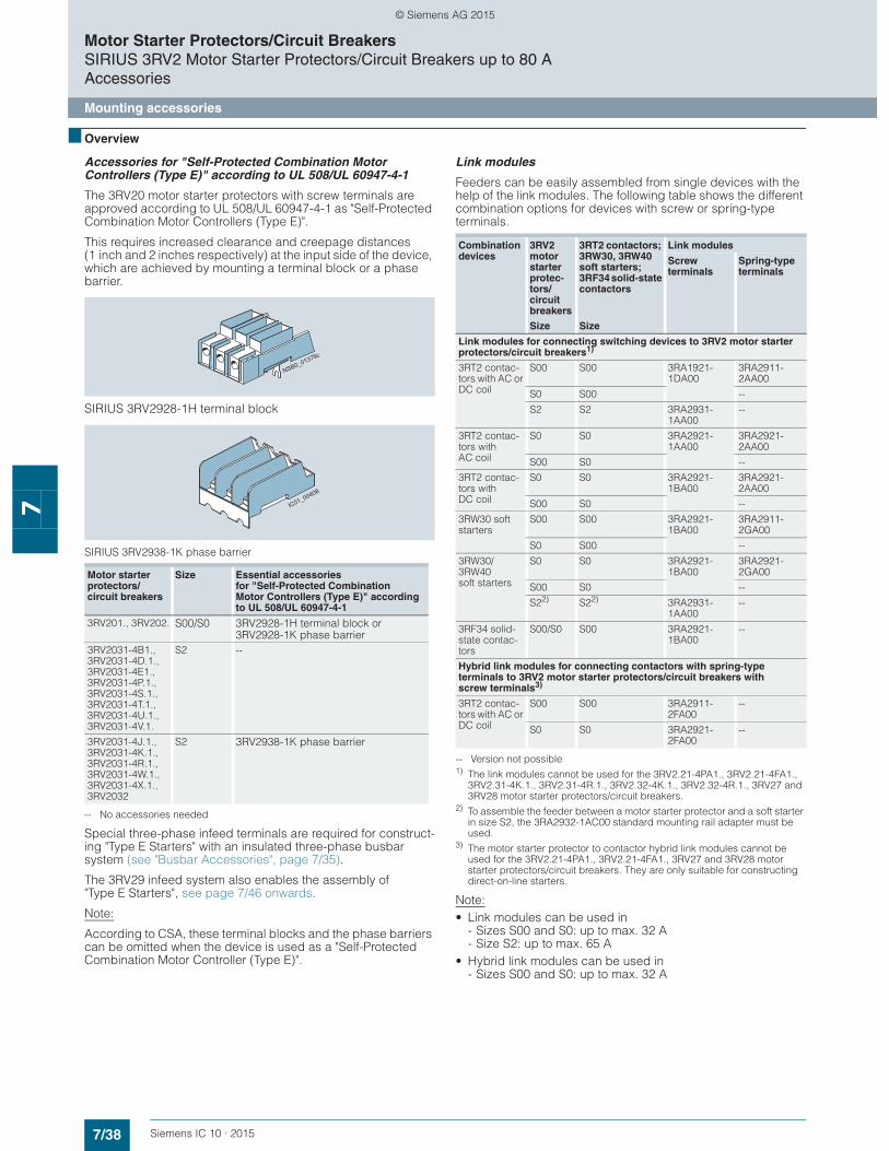
7/38 Siemens IC 10 · 2015
Motor Starter Protectors/Circuit BreakersSIRIUS 3RV2 Motor Starter Protectors/Circuit Breakers up to 80 AAccessories
Mounting accessories
7
■ Overview
Accessories for "Self-Protected Combination Motor Controllers (Type E)" according to UL 508/UL 60947-4-1
The 3RV20 motor starter protectors with screw terminals are approved according to UL 508/UL 60947-4-1 as "Self-Protected Combination Motor Controllers (Type E)".
This requires increased clearance and creepage distances (1 inch and 2 inches respectively) at the input side of the device, which are achieved by mounting a terminal block or a phase barrier.
SIRIUS 3RV2928-1H terminal block
SIRIUS 3RV2938-1K phase barrier
-- No accessories needed
Special three-phase infeed terminals are required for construct-ing "Type E Starters" with an insulated three-phase busbar system (see "Busbar Accessories", page 7/35).
The 3RV29 infeed system also enables the assembly of "Type E Starters", see page 7/46 onwards.
Note:
According to CSA, these terminal blocks and the phase barriers can be omitted when the device is used as a "Self-Protected Combination Motor Controller (Type E)".
Link modules
Feeders can be easily assembled from single devices with the help of the link modules. The following table shows the different combination options for devices with screw or spring-type terminals.
-- Version not possible1) The link modules cannot be used for the 3RV2.21-4PA1., 3RV2.21-4FA1.,
3RV2.31-4K.1., 3RV2.31-4R.1., 3RV2.32-4K.1., 3RV2.32-4R.1., 3RV27 and 3RV28 motor starter protectors/circuit breakers.
2) To assemble the feeder between a motor starter protector and a soft starter in size S2, the 3RA2932-1AC00 standard mounting rail adapter must be used.
3) The motor starter protector to contactor hybrid link modules cannot be used for the 3RV2.21-4PA1., 3RV2.21-4FA1., 3RV27 and 3RV28 motor starter protectors/circuit breakers. They are only suitable for constructing direct-on-line starters.
Note:• Link modules can be used in
- Sizes S00 and S0: up to max. 32 A- Size S2: up to max. 65 A
• Hybrid link modules can be used in- Sizes S00 and S0: up to max. 32 A
Motor starter protectors/circuit breakers
Size Essential accessories for "Self-Protected Combination Motor Controllers (Type E)" according to UL 508/UL 60947-4-1
3RV201., 3RV202. S00/S0 3RV2928-1H terminal block or 3RV2928-1K phase barrier
3RV2031-4B1.,3RV2031-4D.1.,3RV2031-4E1.,3RV2031-4P.1.,3RV2031-4S.1.,3RV2031-4T.1.,3RV2031-4U.1.,3RV2031-4V.1.
S2 --
3RV2031-4J.1., 3RV2031-4K.1., 3RV2031-4R.1., 3RV2031-4W.1., 3RV2031-4X.1., 3RV2032
S2 3RV2938-1K phase barrier
NSB0_01379c
IC01_00408
Combination devices
3RV2 motor starter protec-tors/circuit breakers
Size
3RT2 contactors; 3RW30, 3RW40 soft starters; 3RF34 solid-state contactors
Size
Link modules
Screw terminals
Spring-type terminals
Link modules for connecting switching devices to 3RV2 motor starter protectors/circuit breakers1)
3RT2 contac-tors with AC or DC coil
S00 S00 3RA1921-1DA00
3RA2911-2AA00
S0 S00 --
S2 S2 3RA2931-1AA00
--
3RT2 contac-tors with AC coil
S0 S0 3RA2921-1AA00
3RA2921-2AA00
S00 S0 --
3RT2 contac-tors with DC coil
S0 S0 3RA2921-1BA00
3RA2921-2AA00
S00 S0 --
3RW30 soft starters
S00 S00 3RA2921-1BA00
3RA2911-2GA00
S0 S00 --
3RW30/3RW40soft starters
S0 S0 3RA2921-1BA00
3RA2921-2GA00
S00 S0 --
S22) S22) 3RA2931-1AA00
--
3RF34 solid-state contac-tors
S00/S0 S00 3RA2921-1BA00
--
Hybrid link modules for connecting contactors with spring-type terminals to 3RV2 motor starter protectors/circuit breakers with screw terminals3)
3RT2 contac-tors with AC or DC coil
S00 S00 3RA2911-2FA00
--
S0 S0 3RA2921-2FA00
--
© Siemens AG 2015

7/39Siemens IC 10 · 2015* You can order this quantity or a multiple thereof.Illustrations are approximate
Motor Starter Protectors/Circuit BreakersSIRIUS 3RV2 Motor Starter Protectors/Circuit Breakers up to 80 A
Accessories
Mounting accessories
7
■ Selection and ordering data
Accessories
Version For motor starter protectors/circuit breakers
DT Article No. Priceper PU
PU(UNIT,
SET, M)
PS* PG
Size
Covers
3RV2908-0P
Scale coversSealable, for covering the set current scale
3RV20, 3RV21, 3RV24: S00 ... S2
} 3RV2908-0P 100 10 units 41E
3RT2936-4EA2
Covers for devices with screw terminals (box terminals)Additional touch protection for fasteningto the box terminals (2 units required per device)
Screw terminals
• Main current level S2 B 3RT2936-4EA2 1 1 unit 41B
3RV2928-4AA00
3RV2908-4AA10
Covers for devices with ring terminal lug connection (ensure finger-safety)
Ring terminal lug connections
• Main current level 3RV20: S00, S0
B 3RV2928-4AA00 1 1 unit 41E
• For transverse auxiliary switches B 3RV2908-4AA10 1 1 unit 41E
Fixing accessories
3RV2928-0B
Push-in lugsFor screwing the motor starter protector/circuit breakers onto mounting plates
For each motor starter protector/circuit breakers, two units are required.
S00, S0 A 3RV2928-0B 100 10 units 41E
Tools for opening spring-type terminals
3RA2908-1A
Screwdrivers For all SIRIUS devices with spring-type terminals
Spring-type terminals
Length approx. 200 mm, 3.0 mm x 0.5 mm, titanium gray/black, partially insulated
S00 ... S2 A 3RA2908-1A 1 1 unit 41B
Terminal blocks and phase barriers for "Self-Protected Combination Motor Controllers (Type E)" according to UL 508/UL 60947-4-1
3RV2928-1H
3RV2928-1K
3RV2938-1K
Note:
UL 508/UL 60947-4-1 approval demands 1-inch clearance and 2-inch creepage distance for "Self-Protected Combination Motor Controllers (Type E)". The following terminal blocks or phase barriers must be used for the 3RV20 motor starter protectors with screw terminals. The construction of 3RV20 motor starter protectors with spring-type terminals with the 3RV29 infeed system is also approved as "Self-Protected Combination Motor Controllers (Type E)" according to UL 508/UL 60947-4-1.
The terminal block or phase barriers cannot be used in combination with the 3RV19.5 three-phase busbars.
For construction with three-phase busbars, see "Busbar Accessories" page 7/34 onwards.
Terminal blocks type EFor extended clearance and creepage distances (1 and 2 inch)
S00, S0 } 3RV2928-1H 1 1 unit 41E
Phase barriersFor extended clearance and creepage distances (1 and 2 inch)
S00, S0 } 3RV2928-1K 1 1 unit 41E
S2 A 3RV2938-1K 1 1 unit 41E
© Siemens AG 2015
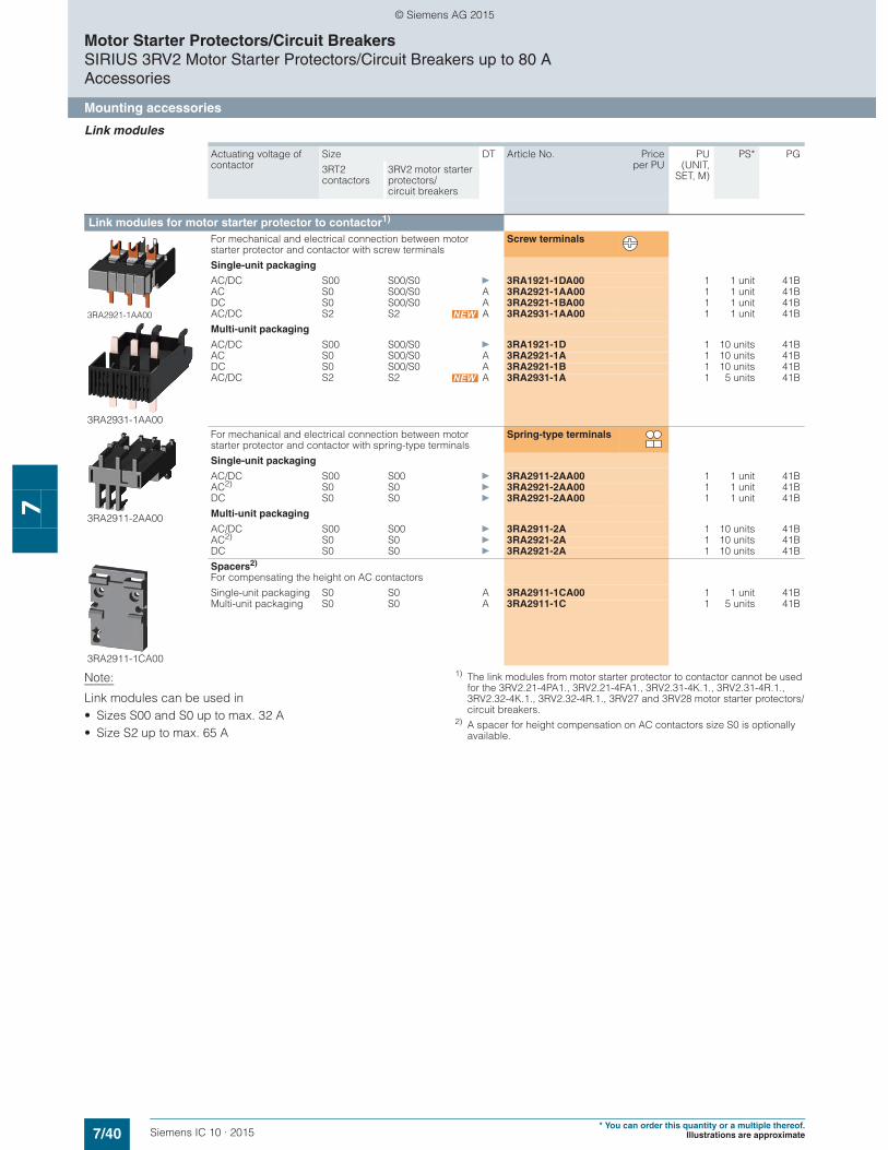
7/40 Siemens IC 10 · 2015* You can order this quantity or a multiple thereof.
Illustrations are approximate
Motor Starter Protectors/Circuit BreakersSIRIUS 3RV2 Motor Starter Protectors/Circuit Breakers up to 80 AAccessories
Mounting accessories
7
Link modules
Note:
Link modules can be used in• Sizes S00 and S0 up to max. 32 A• Size S2 up to max. 65 A
1) The link modules from motor starter protector to contactor cannot be used for the 3RV2.21-4PA1., 3RV2.21-4FA1., 3RV2.31-4K.1., 3RV2.31-4R.1., 3RV2.32-4K.1., 3RV2.32-4R.1., 3RV27 and 3RV28 motor starter protectors/circuit breakers.
2) A spacer for height compensation on AC contactors size S0 is optionally available.
Actuating voltage of contactor
Size DT Article No. Priceper PU
PU(UNIT,
SET, M)
PS* PG
3RT2 contactors
3RV2 motor starter protectors/circuit breakers
Link modules for motor starter protector to contactor1)
3RA2921-1AA00
3RA2931-1AA00
For mechanical and electrical connection between motor starter protector and contactor with screw terminals
Screw terminals
Single-unit packaging
AC/DC S00 S00/S0 } 3RA1921-1DA00 1 1 unit 41BAC S0 S00/S0 A 3RA2921-1AA00 1 1 unit 41BDC S0 S00/S0 A 3RA2921-1BA00 1 1 unit 41BAC/DC S2 S2 A 3RA2931-1AA00 1 1 unit 41B
Multi-unit packaging
AC/DC S00 S00/S0 } 3RA1921-1D 1 10 units 41BAC S0 S00/S0 A 3RA2921-1A 1 10 units 41BDC S0 S00/S0 A 3RA2921-1B 1 10 units 41BAC/DC S2 S2 A 3RA2931-1A 1 5 units 41B
3RA2911-2AA00
For mechanical and electrical connection between motor starter protector and contactor with spring-type terminals
Spring-type terminals
Single-unit packaging
AC/DC S00 S00 } 3RA2911-2AA00 1 1 unit 41BAC2) S0 S0 } 3RA2921-2AA00 1 1 unit 41BDC S0 S0 } 3RA2921-2AA00 1 1 unit 41B
Multi-unit packaging
AC/DC S00 S00 } 3RA2911-2A 1 10 units 41BAC2) S0 S0 } 3RA2921-2A 1 10 units 41BDC S0 S0 } 3RA2921-2A 1 10 units 41B
3RA2911-1CA00
Spacers2)
For compensating the height on AC contactors
Single-unit packaging S0 S0 A 3RA2911-1CA00 1 1 unit 41BMulti-unit packaging S0 S0 A 3RA2911-1C 1 5 units 41B
© Siemens AG 2015
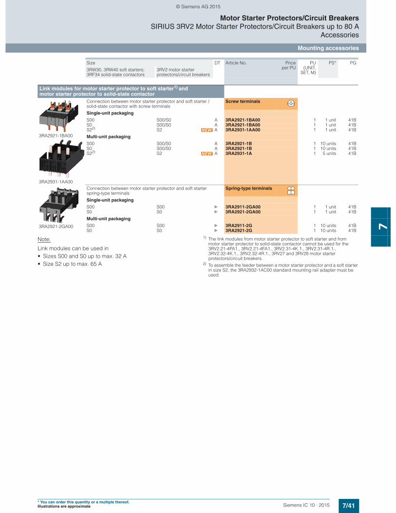
7/41Siemens IC 10 · 2015* You can order this quantity or a multiple thereof.Illustrations are approximate
Motor Starter Protectors/Circuit BreakersSIRIUS 3RV2 Motor Starter Protectors/Circuit Breakers up to 80 A
Accessories
Mounting accessories
7
Note:
Link modules can be used in• Sizes S00 and S0 up to max. 32 A• Size S2 up to max. 65 A
1) The link modules from motor starter protector to soft starter and from motor starter protector to solid-state contactor cannot be used for the 3RV2.21-4PA1., 3RV2.21-4FA1., 3RV2.31-4K.1., 3RV2.31-4R.1., 3RV2.32-4K.1., 3RV2.32-4R.1., 3RV27 and 3RV28 motor starter protectors/circuit breakers.
2) To assemble the feeder between a motor starter protector and a soft starter in size S2, the 3RA2932-1AC00 standard mounting rail adapter must be used.
Size DT Article No. Priceper PU
PU(UNIT,
SET, M)
PS* PG
3RW30, 3RW40 soft starters; 3RF34 solid-state contactors
3RV2 motor starter protectors/circuit breakers
Link modules for motor starter protector to soft starter1) and motor starter protector to solid-state contactor
3RA2921-1BA00
3RA2931-1AA00
Connection between motor starter protector and soft starter / solid-state contactor with screw terminals
Screw terminals
Single-unit packaging
S00 S00/S0 A 3RA2921-1BA00 1 1 unit 41BS0 S00/S0 A 3RA2921-1BA00 1 1 unit 41BS22) S2 A 3RA2931-1AA00 1 1 unit 41B
Multi-unit packaging
S00 S00/S0 A 3RA2921-1B 1 10 units 41BS0 S00/S0 A 3RA2921-1B 1 10 units 41BS22) S2 A 3RA2931-1A 1 5 units 41B
3RA2921-2GA00
Connection between motor starter protector and soft starter spring-type terminals
Spring-type terminals
Single-unit packaging
S00 S00 } 3RA2911-2GA00 1 1 unit 41BS0 S0 } 3RA2921-2GA00 1 1 unit 41B
Multi-unit packaging
S00 S00 } 3RA2911-2G 1 10 units 41BS0 S0 } 3RA2921-2G 1 10 units 41B
© Siemens AG 2015
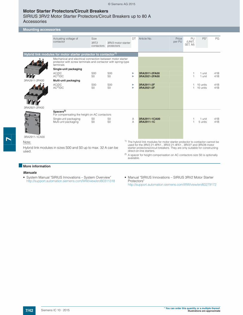
7/42 Siemens IC 10 · 2015* You can order this quantity or a multiple thereof.
Illustrations are approximate
Motor Starter Protectors/Circuit BreakersSIRIUS 3RV2 Motor Starter Protectors/Circuit Breakers up to 80 AAccessories
Mounting accessories
7 Note:
Hybrid link modules in sizes S00 and S0 up to max. 32 A can be used.
1) The hybrid link modules for motor starter protector to contactor cannot be used for the 3RV2.21-4PA1., 3RV2.21-4FA1., 3RV27 and 3RV28 motor starter protectors/circuit breakers. They are only suitable for constructing direct-on-line starters.
2) A spacer for height compensation on AC contactors size S0 is optionally available.
■ More information
Manuals • System Manual "SIRIUS Innovations – System Overview"
http://support.automation.siemens.com/WW/view/en/60311318• Manual "SIRIUS Innovations – SIRIUS 3RV2 Motor Starter
Protectors"http://support.automation.siemens.com/WW/view/en/60279172
Actuating voltage ofcontactor
Size DT Article No. Priceper PU
PU(UNIT,
SET, M)
PS* PG
3RT2 contactors
3RV2 motor starter protectors
Hybrid link modules for motor starter protector to contactor1)
3RA2911-2FA00
3RA2921-2FA00
Mechanical and electrical connection between motor starter protector with screw terminals and contactor with spring-type terminals
Single-unit packaging
AC/DC S00 S00 } 3RA2911-2FA00 1 1 unit 41BAC2)/DC S0 S0 } 3RA2921-2FA00 1 1 unit 41B
Multi-unit packaging
AC/DC S00 S00 } 3RA2911-2F 1 10 units 41BAC2)/DC S0 S0 } 3RA2921-2F 1 10 units 41B
3RA2911-1CA00
Spacers2)
For compensating the height on AC contactors
Single-unit packaging S0 S0 A 3RA2911-1CA00 1 1 unit 41BMulti-unit packaging S0 S0 A 3RA2911-1C 1 5 units 41B
© Siemens AG 2015
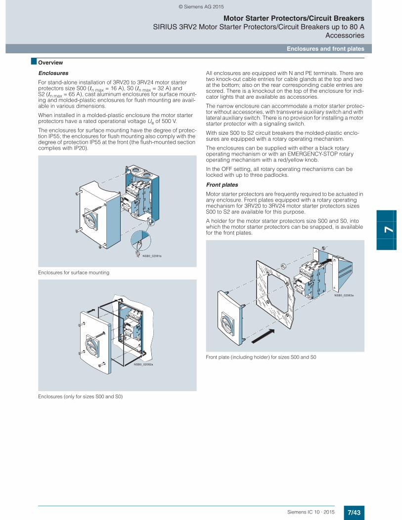
7/43Siemens IC 10 · 2015
Motor Starter Protectors/Circuit BreakersSIRIUS 3RV2 Motor Starter Protectors/Circuit Breakers up to 80 A
Accessories
Enclosures and front plates
7
■ Overview
Enclosures
For stand-alone installation of 3RV20 to 3RV24 motor starter protectors size S00 (In max = 16 A), S0 (In max = 32 A) and S2 (In max = 65 A), cast aluminum enclosures for surface mount-ing and molded-plastic enclosures for flush mounting are avail-able in various dimensions.
When installed in a molded-plastic enclosure the motor starter protectors have a rated operational voltage Ue of 500 V.
The enclosures for surface mounting have the degree of protec-tion IP55; the enclosures for flush mounting also comply with the degree of protection IP55 at the front (the flush-mounted section complies with IP20).
Enclosures for surface mounting
Enclosures (only for sizes S00 and S0)
All enclosures are equipped with N and PE terminals. There are two knock-out cable entries for cable glands at the top and two at the bottom; also on the rear corresponding cable entries are scored. There is a knockout on the top of the enclosure for indi-cator lights that are available as accessories.
The narrow enclosure can accommodate a motor starter protec-tor without accessories, with transverse auxiliary switch and with lateral auxiliary switch. There is no provision for installing a motor starter protector with a signaling switch.
With size S00 to S2 circuit breakers the molded-plastic enclo-sures are equipped with a rotary operating mechanism.
The enclosures can be supplied with either a black rotary operating mechanism or with an EMERGENCY-STOP rotary operating mechanism with a red/yellow knob.
In the OFF setting, all rotary operating mechanisms can be locked with up to three padlocks.
Front plates
Motor starter protectors are frequently required to be actuated in any enclosure. Front plates equipped with a rotary operating mechanism for 3RV20 to 3RV24 motor starter protectors sizes S00 to S2 are available for this purpose.
A holder for the motor starter protectors size S00 and S0, into which the motor starter protectors can be snapped, is available for the front plates.
Front plate (including holder) for sizes S00 and S0
NSB0_02081a
NSB0_02082a
NSB0_02083a
© Siemens AG 2015

7/44 Siemens IC 10 · 2015* You can order this quantity or a multiple thereof.
Illustrations are approximate
Motor Starter Protectors/Circuit BreakersSIRIUS 3RV2 Motor Starter Protectors/Circuit Breakers up to 80 AAccessories
Enclosures and front plates
7
■ Selection and ordering data
1) The rear cable glands cannot be used on 3RV2.11-...2. and 3RV2.21-...2. devices with spring-type terminals.
2) Only valid for lateral auxiliary switches with two auxiliary contacts.
3) If required, an additional N terminal can be mounted (e.g. 8WA1011-1BG11).
4) Not suitable for 3RV2.11-...2. and 3RV2.21-...2. devices with spring-type terminals.
Version Degree of pro-tection
Inte-grated terminals
Width For 3RV20 to 3RV24 motor starter protectors
DT Article No. Priceper PU
PU(UNIT,
SET, M)
PS* PG
mm Size
Molded-plastic enclosures for surface mounting1)
3RV1933-1DA00
With rotary operating mechanism, lockable in 0 position
IP55 N and PE/ground
54(for motor starter protector + lateral auxiliary switch)
S00, S0 } 3RV1923-1CA00 1 1 unit 41E
72(for motor starter protector + lateral auxiliary switch2) + auxiliary release)
S00, S0 } 3RV1923-1DA00 1 1 unit 41E
82(for motor starter protector + lateral auxiliary switch2) + auxiliary release)
S2 A 3RV1933-1DA00 1 1 unit 41E
3RV1923-1FA00, 3RV1933-1GA00
With EMER-GENCY-STOP rotary operating mechanism, lockable in 0 position
IP55 N and PE/ground
54 (for motor starter protector + lateral auxiliary switch)
S00, S0 } 3RV1923-1FA00 1 1 unit 41E
72(for motor starter protector + lateral auxiliary switch2) + auxiliary release)
S00, S0 } 3RV1923-1GA00 1 1 unit 41E
82(for motor starter protector + lateral auxiliary switch2) + auxiliary release)
S2 A 3RV1933-1GA00 1 1 unit 41E
Cast aluminum enclosures for surface mounting1)
3RV1923-1DA01
With rotary operating mechanism, lockable in 0 position
IP65 PE3) 72(for motor starter protector + lateral auxiliary switch2) + auxiliary release)
S00, S0 } 3RV1923-1DA01 1 1 unit 41E
With EMER-GENCY-STOP rotary operating mechanism, lockable in 0 position
IP65 PE3) 72 (for motor starter protector + lateral auxiliary switch2) + auxiliary release)
S00, S0 } 3RV1923-1GA01 1 1 unit 41E
Molded-plastic enclosures for flush mounting4)
3RV1923-2DA00
With rotary operating mechanism, lockable in 0 position
IP55 (front side)
N and PE/ground
72 (for motor starter protector + lateral auxiliary switch2) + auxiliary release)
S00, S0 A 3RV1923-2DA00 1 1 unit 41E
With EMER-GENCY-STOP rotary operating mechanism, lockable in 0 position
IP55 (front side)
N and PE/ground
72(for motor starter protector + lateral auxiliary switch2) + auxiliary release)
S00, S0 A 3RV1923-2GA00 1 1 unit 41E
© Siemens AG 2015

7/45Siemens IC 10 · 2015* You can order this quantity or a multiple thereof.Illustrations are approximate
Motor Starter Protectors/Circuit BreakersSIRIUS 3RV2 Motor Starter Protectors/Circuit Breakers up to 80 A
Accessories
Enclosures and front plates
7
Version Degree of protection
For 3RV20 to 3RV24 motor starter protectors
DT Article No. Priceper PU
PU(UNIT,
SET, M)
PS* PG
Size
Front plates
3RV1923-4B + 3RV1923-4G
Molded-plastic front plates with rotary operating mechanism, lockable in 0 position
For actuation of 3RV2 motor starter protectors in any enclosure
IP55 (front side)
S00 ... S2 } 3RV1923-4B 1 1 unit 41E
Molded-plastic front plates with EMERGENCY-STOP rotary operating mechanism, red/yellow, lockable in 0 position
EMERGENCY-STOP actuation of 3RV2 motor starter protectors in any enclosure
IP55 (front side)
S00 ... S2 A 3RV1923-4E 1 1 unit 41E
Holders for front plates
Holder is mounted on front plate, motor starter protector with and without accessories is snapped in.
-- S00, S0 } 3RV1923-4G 1 1 unit 41E
Version Rated control supply voltage Us
For 3RV20 to 3RV24 motor starter protectors
DT Article No. Priceper PU
PU(UNIT,
SET, M)
PS* PG
V Size
Indicator lights
3RV1903-5B
Indicator lights For all enclosures and front plates
• With LED lamp for versions 110 ... 120 V, with glow lamp for versions 220 ... 500 V
• With colored lenses red, green, yellow, orange and clear
110 ... 120 S00 ... S2 C 3RV1903-5B 1 1 unit 41E220 ... 240 C 3RV1903-5C 1 1 unit 41E380 ... 415 C 3RV1903-5E 1 1 unit 41E480 ... 500 C 3RV1903-5G 1 1 unit 41E
© Siemens AG 2015

7/46 Siemens IC 10 · 2015
Motor Starter Protectors/Circuit BreakersSIRIUS 3RV2 Motor Starter Protectors/Circuit Breakers up to 80 A
3RV29 infeed system
7
■ Overview
The 3RV29 infeed system is a convenient means of energy supply and distribution for a group of several motor starter protectors or complete load feeders with a screw or spring-type connection in sizes S00 and S0 (exception: this system cannot be used for the 3RV21, 3RV27 and 3RV28 motor starter protec-tors/circuit breakers).
The system is based on a basic module complete with a lateral incoming unit (three-phase busbar with infeed). This infeed with spring-type terminals is mounted on the right or left depending on the version and can be supplied with a maximum conductor cross-section of 25 mm2 (with end sleeve). A basic module has two sockets onto each of which a motor starter protector can be snapped.
Expansion modules are available for extending the system (three-phase busbars for system expansion). The individual modules are connected through an expansion plug.
The electrical connection between the three-phase busbars and the motor starter protectors is implemented through plug-in con-nectors. The complete system can be mounted on a TH 35 stan-
dard mounting rail to IEC 60715 and can be expanded as required up to a maximum current carrying capacity of 63 A.
The system is mounted extremely quickly and easily thanks to the simple plug-in technique. Thanks to the lateral infeed, the system also saves space in the control cabinet. The addi-tional overall height required for the infeed unit is only 30 mm. The alternative infeed possibilities on each side offer a high degree of flexibility for configuring the control cabinet: Infeed on left-hand or right-hand side as well as infeed on one side and outfeed on the other side to supply further loads are all possible. A terminal block with spring-type connections in combination with a standard mounting rail enables the integration of not only SIRIUS motor starter protectors but also single-phase, 2-phase and 3-phase components such as 5SY miniature circuit breakers or SIRIUS relay components.
The 3RV29 infeed system is approved in accordance with IEC to 500 V. It is also UL-approved and authorized for "Self-Protected Combination Motor Controller" (Type E starter) as well as for Type F starter (Type E starter + contactor).
SIRIUS 3RV29 infeed systems
NS
B0_
0207
8a
123a
456
3b 7
1
2
3a
4
5
6
7
3b
5
3-phase busbar with infeed3-phase busbar for system expansionExpansion plug Extra-wide expansion plug
End coverPlug-in connectorContactor baseTerminal block
© Siemens AG 2015

7/47Siemens IC 10 · 2015
Motor Starter Protectors/Circuit BreakersSIRIUS 3RV2 Motor Starter Protectors/Circuit Breakers up to 80 A
3RV29 infeed system
7
$ Three-phase busbars with infeed
A three-phase busbar with infeed unit is required for connecting the incoming supply. These modules comprise one infeed module and two sockets which each accept one motor starter protector. A choice of two versions with infeed on the left or right is available. The infeed is connected to spring-type terminals. They permit an infeed with conductor cross-sections of up to 25 mm2 with end sleeves. An end cover is supplied with each module.
% Three-phase busbars for system expansion
The three-phase busbars for system expansion support expan-sion of the system. There is a choice of modules with two or three sockets. The system can be expanded as required up to a maximum current carrying capacity of 63 A. An expansion plug is supplied with each module.
&a Expansion plug
The expansion plug is used for electrical connection of adjacent three-phase busbars. The current carrying capacity of this plug equals 63 A. One expansion plug is supplied with each three-phase busbar for system expansion. Additional expansion plugs are therefore only required as spare parts.
&b Extra-wide expansion plug
The wide expansion plug makes the electrical connection between two three-phase busbars, thus performing the same function as the 3RV2917-5BA00 expansion plug; the electrical characteristics (e.g. a current carrying capacity of 63 A) are identical.
The 3RV2917-5E expansion plug is 10 mm wider than the 3RV2917-5BA00 expansion plug, hence in the plugged state there is a distance of 10 mm between the connected three-phase busbars. This distance can be used to lay the auxiliary current and control current wiring ("wiring duct"). The motor starter protector and contactor can be wired from underneath, which means that the complete cable duct above the system can be omitted.
( End cover
The end cover is used to cover the three-phase busbar at the open end of the system. This cover is therefore only required once for each system. An end cover is supplied with each three-phase busbar system with infeed. Further end covers are therefore only required as spare parts.
) Plug-in connector
The plug-in connector is used for the electrical connection between the three-phase busbar and the 3RV2 motor starter protector. These plug-in connectors are available for screw or spring-type terminals.
* Contactor base
Load feeders can be assembled in the system using the S00 and S0 contactor base. The contactor bases are suitable for contactors sizes S00 and S0 with spring-type and screw termi-nals and are simply snapped onto the three-phase busbars. Direct-on-line starters and reversing starters are possible. One contactor base is required for direct-on-line starters and two are required for reversing starters.
To assemble load feeders for reversing starters, the contactor bases can be arranged alongside each other (90 mm overall width). In this case the mechanical interlocking of the contactors is possible. The S0 contactor bases are also suitable for soft starters size S00 and S0 with screw terminal.
The infeed system is designed for mounting onto a TH 35 standard mounting rail with 7.5 mm overall depth. This standard mounting rail gives the contactor base a stable mounting sur-face to sit on. If standard mounting rails with a depth of 15 mm are used, the spacer connected to the bottom of the contactor base must be knocked out and plugged into the mating piece that is also on the underside. Then the contactor base also has a stable mounting surface. When standard mounting rails with a depth of 7.5 mm are used, the spacer has no function and can be removed.
The link modules are used for direct start load feeders, in which case the use of a contactor base is not absolutely necessary. Motor starter protector and contactor assemblies can then be directly snapped onto the sockets of the three-phase busbars. For feeders of sizes S00 and S0, the corresponding 3RA1921-1...., 3RA2911-2...., 3RA2921-1.... or 3RA2921-2.... link modules should generally be used.
+ Terminal block
The 3RV2917-5D terminal block enables the integration of not only SIRIUS motor starter protectors but also single-phase, 2-phase and 3-phase components. The three phases can be fed out of the system using the terminal block; which means that single-phase loads can also be integrated in the system. The ter-minal block is plugged into the slot of the expansion plug and thus enables outfeeding from the middle or end of the infeed system. The terminal block can be rotated through 180° and be locked to the support modules of the infeed system. In addition, the 45 mm wide TH 35 3RV1917-7B standard mounting rail option for screwing onto the support plate facilitates plugging the single-phase, two-phase and three-phase components onto the infeed system.
© Siemens AG 2015
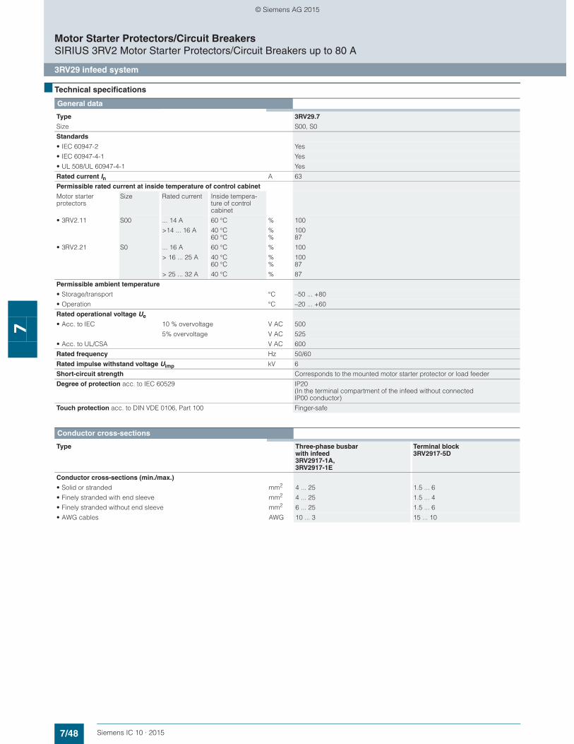
7/48 Siemens IC 10 · 2015
Motor Starter Protectors/Circuit BreakersSIRIUS 3RV2 Motor Starter Protectors/Circuit Breakers up to 80 A
3RV29 infeed system
7
■ Technical specifications
General data
Type 3RV29.7
Size S00, S0
Standards
• IEC 60947-2 Yes
• IEC 60947-4-1 Yes
• UL 508/UL 60947-4-1 Yes
Rated current In A 63
Permissible rated current at inside temperature of control cabinet
Motor starter protectors
Size Rated current Inside tempera-ture of control cabinet
• 3RV2.11 S00 ... 14 A 60 °C % 100
>14 ... 16 A 40 °C60 °C
%%
10087
• 3RV2.21 S0 ... 16 A 60 °C % 100
> 16 ... 25 A 40 °C60 °C
%%
10087
> 25 ... 32 A 40 °C % 87
Permissible ambient temperature
• Storage/transport °C –50 ... +80
• Operation °C –20 ... +60
Rated operational voltage Ue
• Acc. to IEC 10 % overvoltage V AC 500
5% overvoltage V AC 525
• Acc. to UL/CSA V AC 600
Rated frequency Hz 50/60
Rated impulse withstand voltage Uimp kV 6
Short-circuit strength Corresponds to the mounted motor starter protector or load feeder
Degree of protection acc. to IEC 60529 IP20 (In the terminal compartment of the infeed without connected IP00 conductor)
Touch protection acc. to DIN VDE 0106, Part 100 Finger-safe
Conductor cross-sections
Type Three-phase busbarwith infeed 3RV2917-1A,3RV2917-1E
Terminal block 3RV2917-5D
Conductor cross-sections (min./max.)
• Solid or stranded mm2 4 ... 25 1.5 ... 6
• Finely stranded with end sleeve mm2 4 ... 25 1.5 ... 4
• Finely stranded without end sleeve mm2 6 ... 25 1.5 ... 6
• AWG cables AWG 10 ... 3 15 ... 10
© Siemens AG 2015

7/49Siemens IC 10 · 2015* You can order this quantity or a multiple thereof.Illustrations are approximate
Motor Starter Protectors/Circuit BreakersSIRIUS 3RV2 Motor Starter Protectors/Circuit Breakers up to 80 A
3RV29 infeed system
7
■ Selection and ordering data
1) I > 14 A, please note derating; see Manual "SIRIUS Innovations – SIRIUS 3RV2 Motor Starter Protectors", http://support.automation.siemens.com/WW/view/en/60279172.
2) I > 16 A, please note derating; see Manual "SIRIUS Innovations – SIRIUS 3RV2 Motor Starter Protectors", http://support.automation.siemens.com/WW/view/en/60279172.
Type Version For 3RV20, 3RV23, 3RV24 motor starter protectors
DT Article No. Priceper PU
PU(UNIT,
SET, M)
PS* PG
Size
Three-phase busbars with infeed
3RV2917-1A
Three-phase busbars with infeed incl. 3RV2917-6A end cover
For 2 motor starter protectors with screw or spring-type terminals
• With infeed on the left S00, S0 A 3RV2917-1A 1 1 unit 41E
• With infeed on the right S00, S0 A 3RV2917-1E 1 1 unit 41E
Three-phase busbars for system expansion
3RV2917-4A
Three-phase busbarsincl. 3RV2917-5BA00 expansion plug
For motor starter protectors with screw or spring-type terminals
• For 2 motor starter protectors
S00, S0 A 3RV2917-4A 1 1 unit 41E
• For 3 motor starter protectors
S00, S0 A 3RV2917-4B 1 1 unit 41E
Plug-in connectors
3RV2917-5AA00
Plug-in connectors to make contact withthe motor starter protectors
• For spring-type terminals
Spring-type terminals
- Single-unit packaging S001) A 3RV2917-5AA00 1 1 unit 41ES02) A 3RV2927-5AA00 1 1 unit 41E
- Multi-unit packaging S001) A 3RV2917-5A 1 10 units 41ES02) A 3RV2927-5A 1 10 units 41E
3RV2917-5CA00
• For screw terminals Screw terminals
- Single-unit packaging S001) A 3RV2917-5CA00 1 1 unit 41ES02) A 3RV1927-5AA00 1 1 unit 41E
- Multi-unit packaging S001) A 3RV2917-5C 1 10 units 41ES02) A 3RV1927-5A 1 10 units 41E
Type Version For contactors
DT Article No. Priceper PU
PU(UNIT,
SET, M)
PS* PG
Size
Contactor bases
3RV2927-7AA00
Contactor basesfor mounting direct-on-line or reversing starters
Single-unit packaging S00 A 3RV2917-7AA00 1 1 unit 41E
S00, S0 A 3RV2927-7AA00 1 1 unit 41E
© Siemens AG 2015
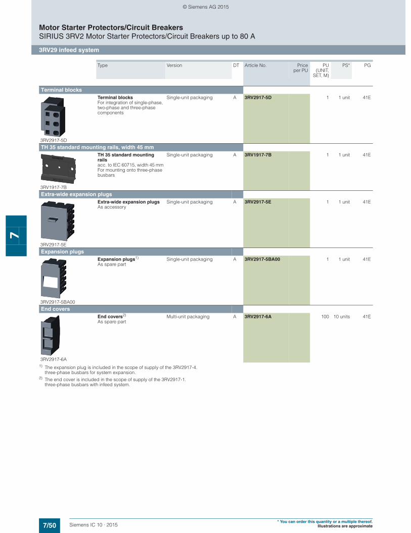
7/50 Siemens IC 10 · 2015* You can order this quantity or a multiple thereof.
Illustrations are approximate
Motor Starter Protectors/Circuit BreakersSIRIUS 3RV2 Motor Starter Protectors/Circuit Breakers up to 80 A
3RV29 infeed system
7
1) The expansion plug is included in the scope of supply of the 3RV2917-4. three-phase busbars for system expansion.
2) The end cover is included in the scope of supply of the 3RV2917-1. three-phase busbars with infeed system.
Type Version DT Article No. Priceper PU
PU(UNIT,
SET, M)
PS* PG
Terminal blocks
3RV2917-5D
Terminal blocks For integration of single-phase, two-phase and three-phase components
Single-unit packaging A 3RV2917-5D 1 1 unit 41E
TH 35 standard mounting rails, width 45 mm
3RV1917-7B
TH 35 standard mounting rails acc. to IEC 60715, width 45 mm For mounting onto three-phase busbars
Single-unit packaging A 3RV1917-7B 1 1 unit 41E
Extra-wide expansion plugs
3RV2917-5E
Extra-wide expansion plugsAs accessory
Single-unit packaging A 3RV2917-5E 1 1 unit 41E
Expansion plugs
3RV2917-5BA00
Expansion plugs1)
As spare partSingle-unit packaging A 3RV2917-5BA00 1 1 unit 41E
End covers
3RV2917-6A
End covers2)
As spare partMulti-unit packaging A 3RV2917-6A 100 10 units 41E
© Siemens AG 2015
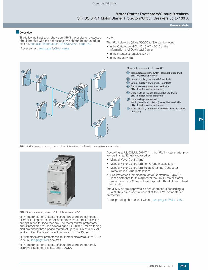
7/51Siemens IC 10 · 2015
Motor Starter Protectors/Circuit BreakersSIRIUS 3RV1 Motor Starter Protectors/Circuit Breakers up to 100 A
General data
7
■ Overview
The following illustration shows our 3RV1 motor starter protector/ circuit breaker with the accessories which can be mounted for size S3, see also "Introduction" ➞ "Overview", page 7/3.
"Accessories", see page 7/69 onwards.
Note:
The 3RV1 devices (sizes S00/S0 to S3) can be found• in the Catalog Add-On IC 10 AO · 2015 at the
Information and Download Center• in the interactive catalog CA 01• in the Industry Mall
SIRIUS 3RV1 motor starter protector/circuit breaker size S3 with mountable accessories
SIRIUS motor starter protector/circuit breaker size S3
3RV1 motor starter protectors/circuit breakers are compact, current limiting motor starter protectors/circuit breakers which are optimized for load feeders. The motor starter protectors/circuit breakers are used according to IEC 60947-2 for switching and protecting three-phase motors of up to 45 kW at 400 V AC and for other loads with rated currents of up to 100 A.
3RV2 motor starter protectors/circuit breakers sizes S00 to S2 up to 80 A, see page 7/21 onwards.
3RV1 motor starter protectors/circuit breakers are generally approved according to IEC and UL/CSA.
According to UL 508/UL 60947-4-1, the 3RV1 motor starter pro-tectors in size S3 are approved as: • "Manual Motor Controllers"• "Manual Motor Controllers" for "Group Installations"• "Manual Motor Controllers Suitable for Tab Conductor
Protection in Group Installations"• "Self-Protected Combination Motor Controllers (Type E)"
Please note that for this approval the 3RV10 motor starter protectors in size S3 must be equipped with additional infeed terminals.
The 3RV1742 are approved as circuit breakers according to UL 489; they are a special variant of the 3RV1 motor starter protectors.
Corresponding short-circuit values, see pages 7/54 to 7/57.
2
7
31
4
5
6
Transverse auxiliary switch (can not be used with 3RV1742 circuit breakers)Lateral auxiliary switch with 2 contactsLateral auxiliary switch with 4 contactsShunt release (can not be used with 3RV11 motor starter protectors)Undervoltage release (can not be used with 3RV11 motor starter protectors)Undervoltage release withleading auxiliary contacts (can not be used with 3RV11 motor starter protectors)Alarm switch (can not be used with 3RV1742 circuit breakers)
Mountable accessories for size S3
1
234
5
7
6
NS
B0_
0218
4c
© Siemens AG 2015
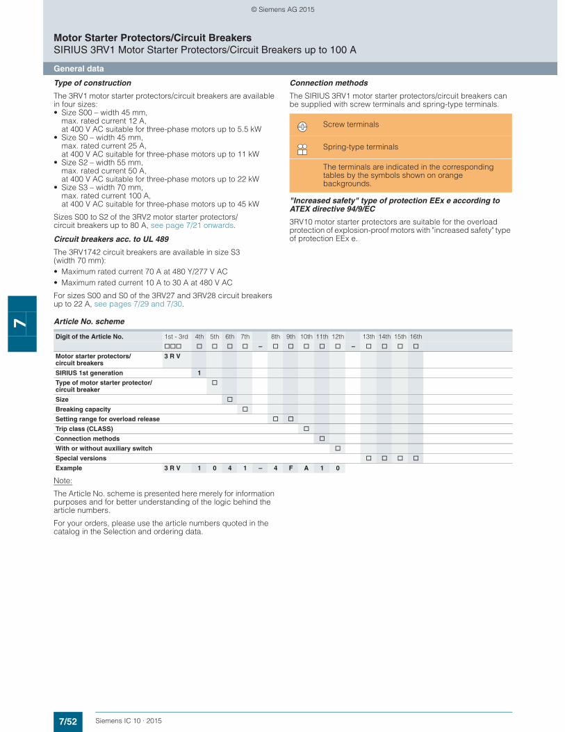
7/52 Siemens IC 10 · 2015
Motor Starter Protectors/Circuit BreakersSIRIUS 3RV1 Motor Starter Protectors/Circuit Breakers up to 100 A
General data
7
Type of construction
The 3RV1 motor starter protectors/circuit breakers are available in four sizes:• Size S00 – width 45 mm,
max. rated current 12 A, at 400 V AC suitable for three-phase motors up to 5.5 kW
• Size S0 – width 45 mm, max. rated current 25 A, at 400 V AC suitable for three-phase motors up to 11 kW
• Size S2 – width 55 mm, max. rated current 50 A, at 400 V AC suitable for three-phase motors up to 22 kW
• Size S3 – width 70 mm, max. rated current 100 A, at 400 V AC suitable for three-phase motors up to 45 kW
Sizes S00 to S2 of the 3RV2 motor starter protectors/circuit breakers up to 80 A, see page 7/21 onwards.
Circuit breakers acc. to UL 489
The 3RV1742 circuit breakers are available in size S3 (width 70 mm):• Maximum rated current 70 A at 480 Y/277 V AC• Maximum rated current 10 A to 30 A at 480 V AC
For sizes S00 and S0 of the 3RV27 and 3RV28 circuit breakers up to 22 A, see pages 7/29 and 7/30.
Connection methods
The SIRIUS 3RV1 motor starter protectors/circuit breakers can be supplied with screw terminals and spring-type terminals.
"Increased safety" type of protection EEx e according to ATEX directive 94/9/EC
3RV10 motor starter protectors are suitable for the overload protection of explosion-proof motors with "increased safety" type of protection EEx e.
Article No. scheme
Note:
The Article No. scheme is presented here merely for information purposes and for better understanding of the logic behind the article numbers.
For your orders, please use the article numbers quoted in the catalog in the Selection and ordering data.
Screw terminals
Spring-type terminals
The terminals are indicated in the corresponding tables by the symbols shown on orange backgrounds.
Digit of the Article No. 1st - 3rd 4th 5th 6th 7th 8th 9th 10th 11th 12th 13th 14th 15th 16th
@@@ @ @ @ @ – @ @ @ @ @ – @ @ @ @
Motor starter protectors/circuit breakers
3 R V
SIRIUS 1st generation 1
Type of motor starter protector/circuit breaker
@
Size @
Breaking capacity @
Setting range for overload release @ @
Trip class (CLASS) @
Connection methods @
With or without auxiliary switch @
Special versions @ @ @ @
Example 3 R V 1 0 4 1 – 4 F A 1 0
© Siemens AG 2015
7/53Siemens IC 10 · 2015
Motor Starter Protectors/Circuit BreakersSIRIUS 3RV1 Motor Starter Protectors/Circuit Breakers up to 100 A
General data
7
■ Application
Operating conditions
3RV1 motor starter protectors/circuit breakers are suitable for use in any climate. They are intended for use in enclosed rooms in which no severe operating conditions (such as dust, caustic vapors, hazardous gases) prevail. When installed in dusty and damp areas, suitable enclosures must be provided.
3RV1 motor starter protectors/circuit breakers can optionally be fed from the top or from below.
The permissible ambient temperatures, the maximum switching capacities, the tripping currents and other boundary conditions can be found in the technical specifications and tripping charac-teristics, see Reference Manual "Protection Equipment – Circuit Breakers · Molded Case Circuit Breakers", http://support.automation.siemens.com/WW/view/en/65032586.
3RV1 motor starter protectors/circuit breakers are suitable for operation in IT systems (IT networks). In this case, the different short-circuit breaking capacity in the IT system must be taken into account, see page 7/55.
Since operational currents, starting currents and current peaks are different even for motors with identical power ratings due to the inrush current, the motor ratings in the selection tables are only guide values. The specific rated and startup data of the motor to be protected is always paramount to the choice of the most suitable motor starter protector/circuit breaker. This also applies to motor starter protectors for transformer protection.
Note:
For the use of 3RV1 motor starter protectors in size S3 in conjunction with highly energy-efficient IE3 motors, please observe the information on dimensioning and configuring, see "Configuration Manual for SIRIUS Controls with IE3 Motors", http://support.automation.siemens.com/WW/view/en/94770820.
More information, see page 3.
Possible uses
The 3RV1 motor starter protectors/circuit breakers can be used:• For short-circuit protection • For motor protection (also with overload relay function) • For system protection • For short-circuit protection for starter combinations • As main and EMERGENCY-STOP switches • For fuse monitoring • For operation in IT systems (IT networks) • For switching of DC currents • As voltage transformer circuit breakers• In areas subject to explosion hazard (ATEX)• Approved as circuit breakers according to UL 489 (3RV1742)
For more details, see Reference Manual "Protection Equipment – Circuit Breakers · Molded Case Circuit Breakers"http://support.automation.siemens.com/WW/view/en/65032586.
© Siemens AG 2015
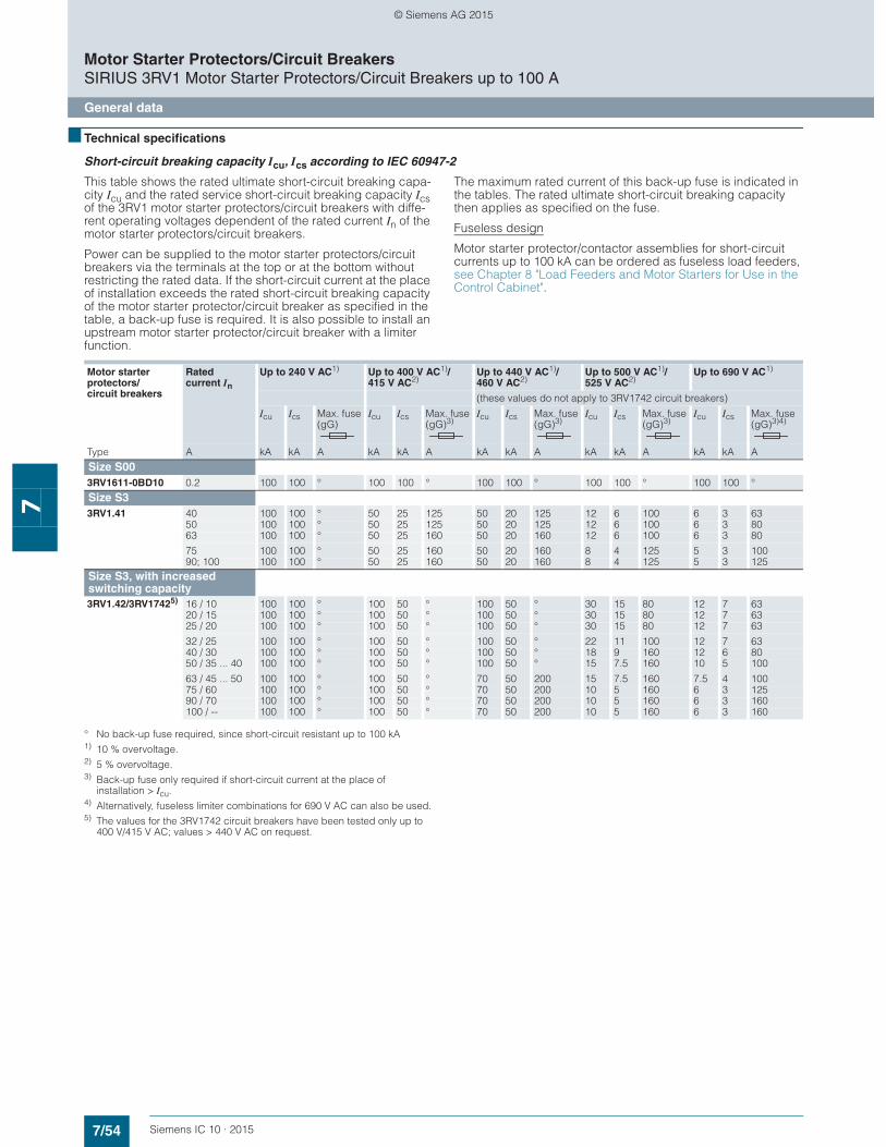
7/54 Siemens IC 10 · 2015
Motor Starter Protectors/Circuit BreakersSIRIUS 3RV1 Motor Starter Protectors/Circuit Breakers up to 100 A
General data
7
■ Technical specifications
Short-circuit breaking capacity Icu, Ics according to IEC 60947-2
This table shows the rated ultimate short-circuit breaking capa-city Icu and the rated service short-circuit breaking capacity Ics of the 3RV1 motor starter protectors/circuit breakers with diffe-rent operating voltages dependent of the rated current In of the motor starter protectors/circuit breakers.
Power can be supplied to the motor starter protectors/circuit breakers via the terminals at the top or at the bottom without restricting the rated data. If the short-circuit current at the place of installation exceeds the rated short-circuit breaking capacity of the motor starter protector/circuit breaker as specified in the table, a back-up fuse is required. It is also possible to install an upstream motor starter protector/circuit breaker with a limiter function.
The maximum rated current of this back-up fuse is indicated in the tables. The rated ultimate short-circuit breaking capacity then applies as specified on the fuse.
Fuseless design
Motor starter protector/contactor assemblies for short-circuit currents up to 100 kA can be ordered as fuseless load feeders, see Chapter 8 "Load Feeders and Motor Starters for Use in the Control Cabinet".
° No back-up fuse required, since short-circuit resistant up to 100 kA1) 10 % overvoltage.2) 5 % overvoltage.3) Back-up fuse only required if short-circuit current at the place of
installation > Icu.4) Alternatively, fuseless limiter combinations for 690 V AC can also be used.5) The values for the 3RV1742 circuit breakers have been tested only up to
400 V/415 V AC; values > 440 V AC on request.
Motor starter protectors/circuit breakers
Rated current In
Up to 240 V AC1) Up to 400 V AC1)/415 V AC2)
Up to 440 V AC1)/460 V AC2)
Up to 500 V AC1)/525 V AC2)
Up to 690 V AC1)
(these values do not apply to 3RV1742 circuit breakers)
Icu Ics Max. fuse (gG)
Icu Ics Max. fuse (gG)3)
Icu Ics Max. fuse (gG)3)
Icu Ics Max. fuse (gG)3)
Icu Ics Max. fuse (gG)3)4)
Type A kA kA A kA kA A kA kA A kA kA A kA kA A
Size S003RV1611-0BD10 0.2 100 100 ° 100 100 ° 100 100 ° 100 100 ° 100 100 °
Size S33RV1.41 40 100 100 ° 50 25 125 50 20 125 12 6 100 6 3 63
50 100 100 ° 50 25 125 50 20 125 12 6 100 6 3 8063 100 100 ° 50 25 160 50 20 160 12 6 100 6 3 80
75 100 100 ° 50 25 160 50 20 160 8 4 125 5 3 10090; 100 100 100 ° 50 25 160 50 20 160 8 4 125 5 3 125
Size S3, with increased switching capacity3RV1.42/3RV17425) 16 / 10 100 100 ° 100 50 ° 100 50 ° 30 15 80 12 7 63
20 / 15 100 100 ° 100 50 ° 100 50 ° 30 15 80 12 7 6325 / 20 100 100 ° 100 50 ° 100 50 ° 30 15 80 12 7 63
32 / 25 100 100 ° 100 50 ° 100 50 ° 22 11 100 12 7 6340 / 30 100 100 ° 100 50 ° 100 50 ° 18 9 160 12 6 8050 / 35 ... 40 100 100 ° 100 50 ° 100 50 ° 15 7.5 160 10 5 100
63 / 45 ... 50 100 100 ° 100 50 ° 70 50 200 15 7.5 160 7.5 4 10075 / 60 100 100 ° 100 50 ° 70 50 200 10 5 160 6 3 12590 / 70 100 100 ° 100 50 ° 70 50 200 10 5 160 6 3 160100 / -- 100 100 ° 100 50 ° 70 50 200 10 5 160 6 3 160
© Siemens AG 2015
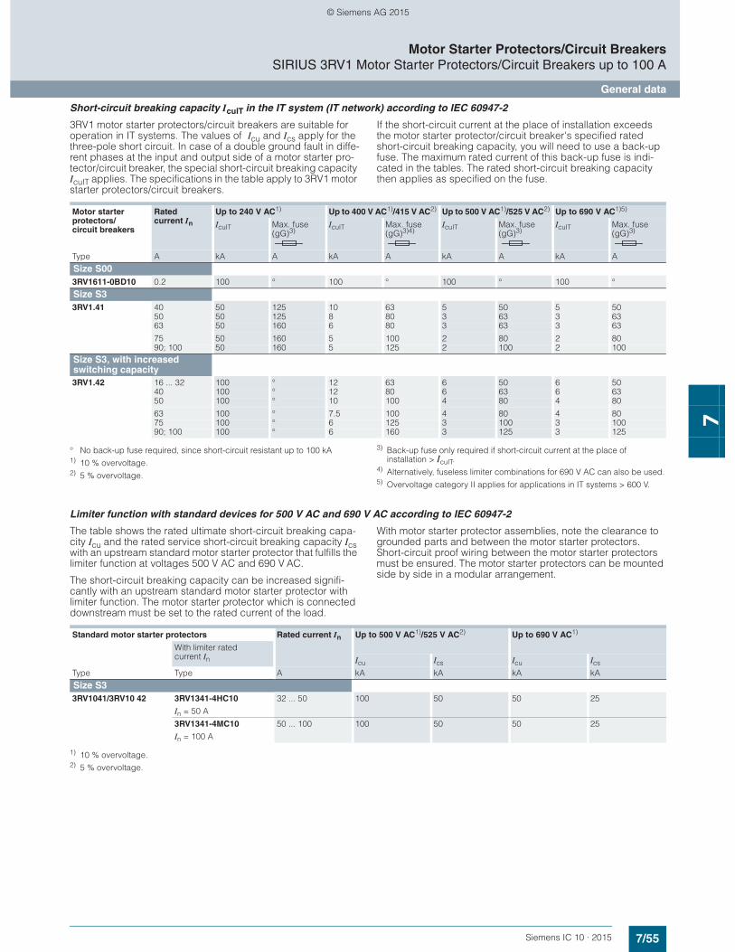
7/55Siemens IC 10 · 2015
Motor Starter Protectors/Circuit BreakersSIRIUS 3RV1 Motor Starter Protectors/Circuit Breakers up to 100 A
General data
7
Short-circuit breaking capacity IcuIT in the IT system (IT network) according to IEC 60947-2
3RV1 motor starter protectors/circuit breakers are suitable for operation in IT systems. The values of Icu and Ics apply for the three-pole short circuit. In case of a double ground fault in diffe-rent phases at the input and output side of a motor starter pro-tector/circuit breaker, the special short-circuit breaking capacity IcuIT applies. The specifications in the table apply to 3RV1 motor starter protectors/circuit breakers.
If the short-circuit current at the place of installation exceeds the motor starter protector/circuit breaker's specified rated short-circuit breaking capacity, you will need to use a back-up fuse. The maximum rated current of this back-up fuse is indi-cated in the tables. The rated short-circuit breaking capacity then applies as specified on the fuse.
° No back-up fuse required, since short-circuit resistant up to 100 kA1) 10 % overvoltage.2) 5 % overvoltage.
3) Back-up fuse only required if short-circuit current at the place ofinstallation > IcuIT.
4) Alternatively, fuseless limiter combinations for 690 V AC can also be used.5) Overvoltage category II applies for applications in IT systems > 600 V.
Limiter function with standard devices for 500 V AC and 690 V AC according to IEC 60947-2
The table shows the rated ultimate short-circuit breaking capa-city Icu and the rated service short-circuit breaking capacity Ics with an upstream standard motor starter protector that fulfills the limiter function at voltages 500 V AC and 690 V AC.
The short-circuit breaking capacity can be increased signifi-cantly with an upstream standard motor starter protector with limiter function. The motor starter protector which is connected downstream must be set to the rated current of the load.
With motor starter protector assemblies, note the clearance to grounded parts and between the motor starter protectors. Short-circuit proof wiring between the motor starter protectors must be ensured. The motor starter protectors can be mounted side by side in a modular arrangement.
1) 10 % overvoltage.2) 5 % overvoltage.
Motor starter protectors/circuit breakers
Rated current In
Up to 240 V AC1) Up to 400 V AC1)/415 V AC2) Up to 500 V AC1)/525 V AC2) Up to 690 V AC1)5)
IcuIT Max. fuse (gG)3)
IcuIT Max. fuse (gG)3)
IcuIT Max. fuse (gG)3)4)
IcuIT Max. fuse (gG)3)
Type A kA A kA A kA A kA A
Size S003RV1611-0BD10 0.2 100 ° 100 ° 100 ° 100 °
Size S33RV1.41 40 50 125 10 63 5 50 5 50
50 50 125 8 80 3 63 3 6363 50 160 6 80 3 63 3 63
75 50 160 5 100 2 80 2 8090; 100 50 160 5 125 2 100 2 100
Size S3, with increased switching capacity3RV1.42 16 ... 32 100 ° 12 63 6 50 6 50
40 100 ° 12 80 6 63 6 6350 100 ° 10 100 4 80 4 80
63 100 ° 7.5 100 4 80 4 8075 100 ° 6 125 3 100 3 10090; 100 100 ° 6 160 3 125 3 125
Standard motor starter protectors Rated current In Up to 500 V AC1)/525 V AC2) Up to 690 V AC1)
With limiter rated current In Icu Ics Icu Ics
Type Type A kA kA kA kA
Size S33RV1041/3RV10 42 3RV1341-4HC10
In = 50 A
32 ... 50 100 50 50 25
3RV1341-4MC10
In = 100 A
50 ... 100 100 50 50 25
© Siemens AG 2015
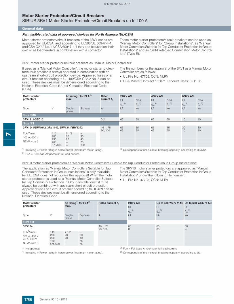
7/56 Siemens IC 10 · 2015
Motor Starter Protectors/Circuit BreakersSIRIUS 3RV1 Motor Starter Protectors/Circuit Breakers up to 100 A
General data
7
Permissible rated data of approved devices for North America (UL/CSA)
Motor starter protectors/circuit breakers of the 3RV1 series are approved for UL/CSA, and according to UL508/UL 60947-4-1 and CSA C22.2 No. 14/CSA 60947-4-1 they can be used on their own or as load feeders in combination with a contactor.
These motor starter protectors/circuit breakers can be used as "Manual Motor Controllers" for "Group Installations", as "Manual Motor Controllers Suitable for Tap Conductor Protection in Group Installations" and as "Self-Protected Combination Motor Control-lers" (Type E).
3RV1 motor starter protectors/circuit breakers as "Manual Motor Controllers"
If used as a "Manual Motor Controller", the motor starter protec-tor/circuit breaker is always operated in combination with an upstream short-circuit protection device. Approved fuses or a circuit breaker according to UL 489/CSA C22.2 No. 5 can be used. These devices must be dimensioned according to the National Electrical Code (UL) or Canadian Electrical Code (CSA).
The file numbers for the approval of the 3RV1 as a Manual Motor Controller are as follows: • UL File No. 47705, CCN: NLRV• CSA Master Contract 165071, Product Class: 3211 05
1) hp rating = Power rating in horse power (maximum motor rating).2) FLA = Full Load Amps/motor full load current.
3) Corresponds to "short-circuit breaking capacity" according to UL/CSA.
3RV10 motor starter protectors as "Manual Motor Controllers Suitable for Tap Conductor Protection in Group Installations"
The application as "Manual Motor Controllers Suitable for Tap Conductor Protection in Group Installations" is only available for UL. CSA does not recognize this approval! When the motor starter protector is used as a "Manual Motor Controller Suitable for Tap Conductor Protection in Group Installations", it must always be combined with upstream short-circuit protection. Approved fuses or a circuit breaker according to UL 489 can be used. These devices must be dimensioned according to the National Electrical Code.
The 3RV10 motor starter protectors are approved as "Manual Motor Controllers Suitable for Tap Conductor Protection in Group Installations" under the following file number:• UL File No. 47705, CCN: NLRV
-- No approval1) hp rating = Power rating in horse power (maximum motor rating).
2) FLA = Full Load Amps/motor full load current.3) Corresponds to "short-circuit breaking capacity" according to UL.
Motor starter protectors
hp rating1) for FLA2) max.
Rated current In
240 V AC 480 V AC 600 V AC
UL CSA UL CSA UL CSA
Ibc3) Ibc
3) Ibc3) Ibc
3) Ibc3) Ibc
3)
Type V Single-phase
3-phase A kA kA kA kA kA kA
Size S003RV1611-0BD10 0.2 65 65 65 65 10 10
Size S33RV1041/3RV1042, 3RV1142, 3RV1341/3RV1342 16 ... 75 65 65 65 65 30 30
90; 100 65 65 65 65 10 10FLA2) max.
100 A, 600 V
NEMA size 3
115 7 1/2 --200 20 30230 20 40460 -- 75575/600 -- 100
Motor starter protectors
hp rating1) for FLA2) max.
Rated current In 240 V AC Up to 480 Y/277 V AC Up to 600 Y/347 V AC
UL UL UL
Ibc3) Ibc
3) Ibc3)
Type V Single-phase
3-phase A kA kA kA
Size S33RV104. 16 ... 75 65 65 30
90; 100 65 65 --FLA2) max.
100 A, 480 V75 A, 600 V
NEMA size 3
115 7 1/2 --200 20 30230 20 40460 -- 75575/600 -- 75
© Siemens AG 2015
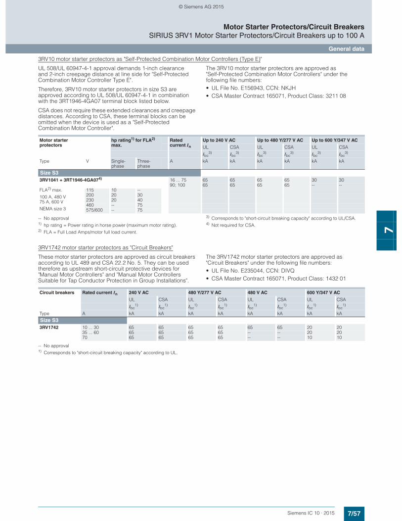
7/57Siemens IC 10 · 2015
Motor Starter Protectors/Circuit BreakersSIRIUS 3RV1 Motor Starter Protectors/Circuit Breakers up to 100 A
General data
7
3RV10 motor starter protectors as "Self-Protected Combination Motor Controllers (Type E)"
UL 508/UL 60947-4-1 approval demands 1-inch clearance and 2-inch creepage distance at line side for "Self-Protected Combination Motor Controller Type E".
Therefore, 3RV10 motor starter protectors in size S3 are approved according to UL 508/UL 60947-4-1 in combination with the 3RT1946-4GA07 terminal block listed below.
CSA does not require these extended clearances and creepage distances. According to CSA, these terminal blocks can be omitted when the device is used as a "Self-Protected Combination Motor Controller".
The 3RV10 motor starter protectors are approved as "Self-Protected Combination Motor Controllers" under the following file numbers: • UL File No. E156943, CCN: NKJH• CSA Master Contract 165071, Product Class: 3211 08
-- No approval1) hp rating = Power rating in horse power (maximum motor rating).2) FLA = Full Load Amps/motor full load current.
3) Corresponds to "short-circuit breaking capacity" according to UL/CSA.4) Not required for CSA.
3RV1742 motor starter protectors as "Circuit Breakers"
These motor starter protectors are approved as circuit breakers according to UL 489 and CSA 22.2 No. 5. They can be used therefore as upstream short-circuit protective devices for "Manual Motor Controllers" and "Manual Motor Controllers Suitable for Tap Conductor Protection in Group Installations".
The 3RV1742 motor starter protectors are approved as "Circuit Breakers" under the following file numbers:• UL File No. E235044, CCN: DIVQ• CSA Master Contract 165071, Product Class: 1432 01
-- No approval1) Corresponds to "short-circuit breaking capacity" according to UL.
Motor starter protectors
hp rating1) for FLA2) max.
Rated current In
Up to 240 V AC Up to 480 Y/277 V AC Up to 600 Y/347 V AC
UL CSA UL CSA UL CSA
Ibc3) Ibc
3) Ibc3) Ibc
3) Ibc3) Ibc
3)
Type V Single-phase
Three-phase
A kA kA kA kA kA kA
Size S33RV1041 + 3RT1946-4GA074) 16 ... 75 65 65 65 65 30 30
90; 100 65 65 65 65 -- --FLA2) max.
100 A, 480 V75 A, 600 V
NEMA size 3
115 10 --200 20 30230 20 40460 -- 75575/600 -- 75
Circuit breakers Rated current In 240 V AC 480 Y/277 V AC 480 V AC 600 Y/347 V AC
UL CSA UL CSA UL CSA UL CSA
Ibc1) Ibc
1) Ibc1) Ibc
1) Ibc1) Ibc
1) Ibc1) Ibc
1)
Type A kA kA kA kA kA kA kA kA
Size S33RV1742 10 ... 30 65 65 65 65 65 65 20 20
35 ... 60 65 65 65 65 -- -- 20 2070 65 65 65 65 -- -- 10 10
© Siemens AG 2015

7/58 Siemens IC 10 · 2015
Motor Starter Protectors/Circuit BreakersSIRIUS 3RV1 Motor Starter Protectors/Circuit Breakers up to 100 A
General data
7
1) "Technical Specifications" for 3RV1611 voltage transformer circuit breakers, see page 7/60.
For short-circuit breaking capacity Icu, Ics see Reference Manual "Protection Equipment – Circuit Breakers · Molded Case Circuit Breakers" http://support.automation.siemens.com/WW/view/en/65032586.
General data
Type 3RV16111) 3RV1.4. 3RV1742
Size S00 S3 S3
Dimensions (W x H x D) mm 45 x 90 x 70 70 x 165 x 169 70 x 168 x 169
Standards • IEC 60947-1, EN 60947-1 (VDE 0660 Part 100) Yes• IEC 60947-2, EN 60947-2 (VDE 0660 Part 101) Yes• IEC 60947-4-1, EN 60947-4-1 (VDE 0660 Part 102) Yes No• UL 508/UL 60947-4-1, CSA C22.2 No.14/CSA 60947-4-1 Yes No• UL 489, CSA C22.2 No. 5 No Yes
Number of poles 3
Max. rated current In max (= max. rated operational current Ie)
A 12 100 70
Permissible ambient temperature• Storage/transport °C –50 ... +80 • Operation °C –20 ... +70 (current reduction above +60 °C)
Permissible rated current at inside temperature of control cabinet • +60 °C % 100• +70 °C % 87
Permissible rated current at ambient temperature of enclosure(applies for motor starter protector inside enclosure)• +35 °C % 100• +60 °C % 87
Rated operational voltage Ue • Acc. to IEC V AC 690 (with molded-plastic enclosure 500 V)• Acc. to UL/CSA V AC 600
Rated frequency Hz 50/60
Rated insulation voltage Ui V 690
Rated impulse withstand voltage Uimp kV 6
Utilization category • IEC 60947-2 (motor starter protector/circuit breaker) A• IEC 60947-4-1 (motor starter) AC-3 --
Trip class CLASS Acc. to IEC 60947-4-1 10 10/20 --
DC short-circuit breaking capacity (time constant t = 5 ms) • 1 conducting path 150 V DC kA 10• 2 conducting paths in series 300 V DC kA 10• 3 conducting paths in series 450 V DC kA 10
Power loss Pv for each motor starter protector/circuit breaker Dependent on the rated current In (upper setting range)
In: 16 ... 63 A W -- 20
In: 75 and 90 A W -- 30In: 100 A W -- 38
In: 10 A W -- 8In: 15 ... 35 A W -- 12In: 40 ... 70 A W -- 21
Shock resistance Acc. to IEC 60068-2-27 g/ms 25/11 (square and sine pulse)
Degree of protection Acc. to IEC 60529 IP20 (IP00 terminal compartment)
Touch protection Acc. to EN 50274 Finger-safe for vertical contact from the front
Temperature compensation Acc. to IEC 60947-4-1 °C –20 ... +60
Phase failure sensitivity Acc. to IEC 60947-4-1 Yes (does not apply for 3RV134 motor starter protectors)
No
Explosion protection – Safe operation of motors with "increased safety" type of protection
Yes, for 3RV10 (CLASS 10) No
EC type test certificate number according to directive 94/9/EC (ATEX)
DMT 02 ATEX F 001 II (2) GD, DMT 02 ATEX F 001 N1 II (2) GD
Isolating function Acc. to IEC 60947-2 YesMain and EMERGENCY-STOP switch characteristics (with corresponding accessories)
Acc. to DIN EN 60204-1 Yes
Protective separation between main and auxiliary circuits, required for PELV applications
Acc. to IEC 60947-1
• Up to 400 V +10 % Yes• Up to 415 V +5 % (higher voltages on request) Yes
Permissible mounting position Any, acc. to IEC 60447 start command "I" right-hand side or top
Mechanical endurance Operating cycles 100 000 50 000
Electrical endurance Operating cycles 100 000 25 000
Max. switching frequency per hour (motor starts) 1/h 15
W
H
D
Rper conducting pathP
Ι 2 3×---------------=
© Siemens AG 2015
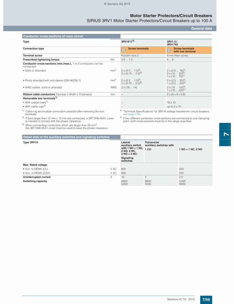
7/59Siemens IC 10 · 2015
Motor Starter Protectors/Circuit BreakersSIRIUS 3RV1 Motor Starter Protectors/Circuit Breakers up to 100 A
General data
7
1) Cable lug and busbar connection possible after removing the box terminals.
2) If bars larger than 12 mm x 10 mm are connected, a 3RT1946-4EA1 cover is needed to comply with the phase clearance.
3) When connecting conductors which are larger than 25 mm2, the 3RT1946-4EA1 cover must be used to keep the phase clearance.
4) "Technical Specifications" for 3RV16 voltage transformer circuit breakers, see page 7/60.
5) If two different conductor cross-sections are connected to one clamping point, both cross-sections must be in the range specified.
Conductor cross-sections of main circuit
Type 3RV16114) 3RV1.4./3RV1742
Connection type Screw terminals Screw terminals with box terminal
Terminal screw Pozidriv size 2 4 mm Allen screw
Prescribed tightening torque Nm 0.8 ... 1.2 4 ... 6
Conductor cross-sections (min./max.), 1 or 2 conductors can be connected
• Solid or stranded mm2 2 x (0.5 ... 1.5)5), 2 x (0.75 ... 2.5)5)
2 x (2.5 ... 16)5),2 x (10 ... 50)5), 1 x (10 ... 70)5)
• Finely stranded with end sleeve (DIN 46228-1) mm2 2 x (0.5 ... 1.5)5), 2 x (0.75 ... 2.5)5)
2 x (2.5 ... 35)5), 1 x (2.5 ... 50)5)
• AWG cables, solid or stranded AWG 2 x (18 ... 14) 2 x (10 ... 1/0)5), 1 x (10 ... 2/0)5)
Ribbon cable conductors (Number x Width x Thickness) mm -- 2 x (6 x 9 x 0.8)
Removable box terminals1)
• With copper bars2) -- 18 x 10
• With cable lugs3) -- up to 2 x 70
Rated data of the auxiliary switches and signaling switches
Type 3RV19 Lateral auxiliary switch with 1 NO + 1 NC, 2 NO, 2 NC, 2 NO + 2 NC;
Signaling switches
Transverse auxiliary switches with
1 CO 1 NO + 1 NC, 2 NO
Max. Rated voltage
• Acc. to NEMA (UL) V AC 600 250
• Acc. to NEMA (CSA) V AC 600 250
Uninterrupted current A 10 5 2.5
Switching capacity A600 Q300
B600 R300
C300 R300
© Siemens AG 2015
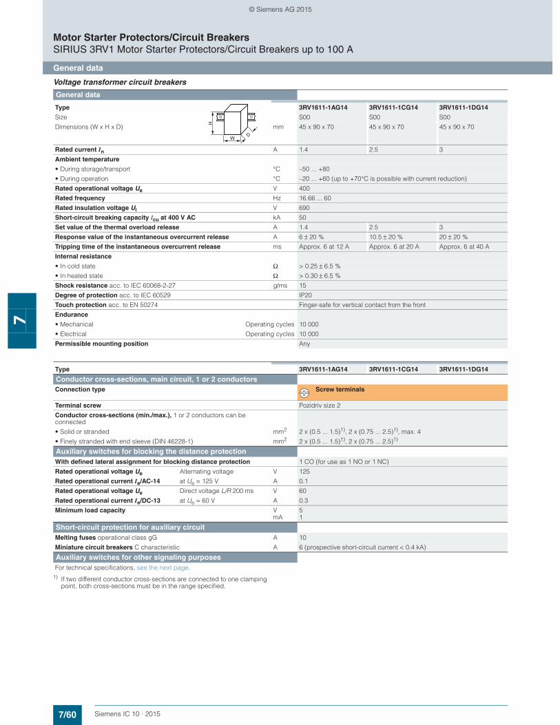
7/60 Siemens IC 10 · 2015
Motor Starter Protectors/Circuit BreakersSIRIUS 3RV1 Motor Starter Protectors/Circuit Breakers up to 100 A
General data
7
Voltage transformer circuit breakers
1) If two different conductor cross-sections are connected to one clamping point, both cross-sections must be in the range specified.
General data
Type 3RV1611-1AG14 3RV1611-1CG14 3RV1611-1DG14
Size S00 S00 S00
Dimensions (W x H x D) mm 45 x 90 x 70 45 x 90 x 70 45 x 90 x 70
Rated current In A 1.4 2.5 3
Ambient temperature
• During storage/transport °C –50 ... +80
• During operation °C –20 ... +60 (up to +70°C is possible with current reduction)
Rated operational voltage Ue V 400
Rated frequency Hz 16.66 ... 60
Rated insulation voltage Ui V 690
Short-circuit breaking capacity Icu at 400 V AC kA 50
Set value of the thermal overload release A 1.4 2.5 3
Response value of the instantaneous overcurrent release A 6 ± 20 % 10.5 ± 20 % 20 ± 20 %
Tripping time of the instantaneous overcurrent release ms Approx. 6 at 12 A Approx. 6 at 20 A Approx. 6 at 40 A
Internal resistance
• In cold state Ω > 0.25 ± 6.5 %
• In heated state Ω > 0.30 ± 6.5 %
Shock resistance acc. to IEC 60068-2-27 g/ms 15
Degree of protection acc. to IEC 60529 IP20
Touch protection acc. to EN 50274 Finger-safe for vertical contact from the front
Endurance
• Mechanical Operating cycles 10 000
• Electrical Operating cycles 10 000
Permissible mounting position Any
W
H
D
Type 3RV1611-1AG14 3RV1611-1CG14 3RV1611-1DG14
Conductor cross-sections, main circuit, 1 or 2 conductorsConnection type Screw terminals
Terminal screw Pozidriv size 2
Conductor cross-sections (min./max.), 1 or 2 conductors can be connected
• Solid or stranded mm2 2 x (0.5 ... 1.5)1), 2 x (0.75 ... 2.5)1), max. 4
• Finely stranded with end sleeve (DIN 46228-1) mm2 2 x (0.5 ... 1.5)1), 2 x (0.75 ... 2.5)1)
Auxiliary switches for blocking the distance protectionWith defined lateral assignment for blocking distance protection 1 CO (for use as 1 NO or 1 NC)
Rated operational voltage Ue Alternating voltage V 125
Rated operational current Ie/AC-14 at Ue = 125 V A 0.1
Rated operational voltage Ue Direct voltage L/R 200 ms V 60
Rated operational current Ie/DC-13 at Ue = 60 V A 0.3
Minimum load capacity V 5mA 1
Short-circuit protection for auxiliary circuitMelting fuses operational class gG A 10
Miniature circuit breakers C characteristic A 6 (prospective short-circuit current < 0.4 kA)
Auxiliary switches for other signaling purposesFor technical specifications, see the next page.
© Siemens AG 2015

7/61Siemens IC 10 · 2015
Motor Starter Protectors/Circuit BreakersSIRIUS 3RV1 Motor Starter Protectors/Circuit Breakers up to 100 A
General data
7
Mountable accessories
Front transverse auxiliary switches
Switching capacity for different voltages
1 CO 1 NO + 1 NC, 2 NO
Rated operational current Ie• At AC-15, alternating voltage
- 24 V A 4 2- 230 V A 3 0.5
• At AC-12 = Ith, alternating voltage- 24 V A 10 2.5- 230 V A 10 2.5
• At DC-13, direct voltage L/R 200 ms- 24 V A 1 1- 48 V A -- 0.3- 60 V A -- 0.15- 110 V A 0.22 --- 220 V A 0.1 --
Minimum load capacity V 17mA 1
Front transverse solid-state compatible auxiliary switches
Switching capacity for different voltages
1 CO
Rated operational voltage Ue Alternating voltage V 125
Rated operational current Ie/AC-14 at Ue = 125 V A 0.1
Rated operational voltage Ue Direct voltage L/R 200 ms V 60
Rated operational current Ie/DC-13 at Ue = 60 V A 0.3
Minimum load capacity V 5mA 1
Lateral auxiliary switches with signaling switch
Switching capacity for different voltages: Lateral auxiliary switch with 1 NO + 1 NC, 2 NO, 2 NC, 2 NO + 2 NCSignaling switch
Rated operational current Ie
• At AC-15, alternating voltage- 24 V A 6- 230 V A 4- 400 V A 3- 690 V A 1
• At AC-12 = Ith, alternating voltage- 24 V A 10- 230 V A 10- 400 V A 10- 690 V A 10
• At DC, direct voltage L/R 200 ms- 24 V A 2- 110 V A 0.5- 220 V A 0.25- 440 V A 0.1
Minimum load capacity V 17mA 1
Auxiliary releases
Undervoltage releases Shunt releases
Power consumption
• During pick-up- AC voltages VA/W 20.2/13 20.2/13- DC voltages W 20 13 ... 80
• During uninterrupted duty- AC voltages VA/W 7.2/2.4 --- DC voltages W 2.1 --
Response voltage
• Tripping V 0.35 ... 0.7 x Us 0.7 ... 1.1 x Us
• Pick-up V 0.85 ... 1.1 x Us --
Opening time maximum ms 20
© Siemens AG 2015
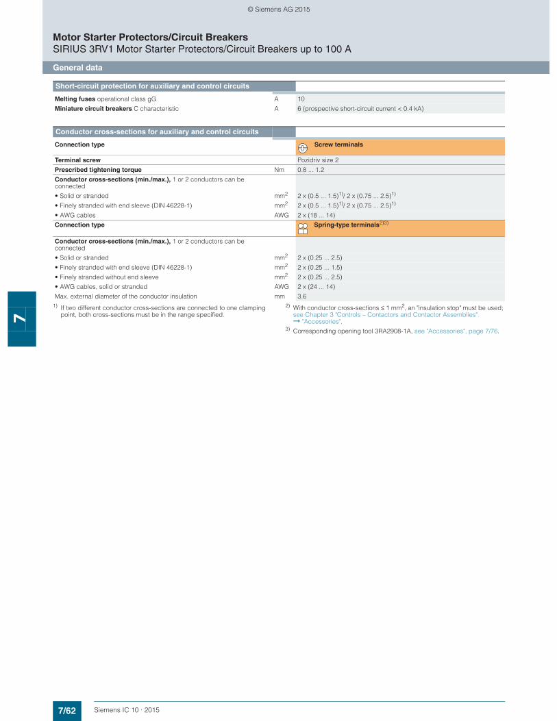
7/62 Siemens IC 10 · 2015
Motor Starter Protectors/Circuit BreakersSIRIUS 3RV1 Motor Starter Protectors/Circuit Breakers up to 100 A
General data
7
1) If two different conductor cross-sections are connected to one clamping point, both cross-sections must be in the range specified.
2) With conductor cross-sections ≤ 1 mm2, an "insulation stop" must be used; see Chapter 3 "Controls – Contactors and Contactor Assemblies". ➞ "Accessories".
3) Corresponding opening tool 3RA2908-1A, see "Accessories", page 7/76.
Short-circuit protection for auxiliary and control circuits
Melting fuses operational class gG A 10
Miniature circuit breakers C characteristic A 6 (prospective short-circuit current < 0.4 kA)
Conductor cross-sections for auxiliary and control circuits
Connection type Screw terminals
Terminal screw Pozidriv size 2
Prescribed tightening torque Nm 0.8 ... 1.2
Conductor cross-sections (min./max.), 1 or 2 conductors can be connected
• Solid or stranded mm2 2 x (0.5 ... 1.5)1)/ 2 x (0.75 ... 2.5)1)
• Finely stranded with end sleeve (DIN 46228-1) mm2 2 x (0.5 ... 1.5)1)/ 2 x (0.75 ... 2.5)1)
• AWG cables AWG 2 x (18 ... 14)
Connection type Spring-type terminals2)3)
Conductor cross-sections (min./max.), 1 or 2 conductors can be connected
• Solid or stranded mm2 2 x (0.25 ... 2.5)
• Finely stranded with end sleeve (DIN 46228-1) mm2 2 x (0.25 ... 1.5)
• Finely stranded without end sleeve mm2 2 x (0.25 ... 2.5)
• AWG cables, solid or stranded AWG 2 x (24 ... 14)
Max. external diameter of the conductor insulation mm 3.6
© Siemens AG 2015

7/63Siemens IC 10 · 2015* You can order this quantity or a multiple thereof.Illustrations are approximate
Motor Starter Protectors/Circuit BreakersSIRIUS 3RV1 Motor Starter Protectors up to 100 A
For motor protection
7
■ Selection and ordering data
CLASS 10, without auxiliary switches
CLASS 20, without auxiliary switches
1) Guide value for 4-pole standard motors at 50 Hz 400 V AC. The actual starting and rated data of the motor to be protected must be considered when selecting the units.
2) For the use of 3RV104. motor starter protectors with an energy-efficient IE3 motor we recommend using a contactor for normal switching duty, see also page 7/53.
Auxiliary switches and other accessories can be ordered separately (see "Accessories" page 7/70 onwards).
Multi-unit/reusable packaging available on request.
Rated current
Suitable for three-phase motors1) with P
Setting range for thermal overload release
Instantaneous overcurrent releases
Short-circuit breaking capacity at 400 V AC
DT Screw terminals PU(UNIT,
SET, M)
PS* PG
In Icu Article No. Priceper PU
A kW A A kA
Size S3
3RV1041-4LA10
40 18.5 28 ... 40 520 50 } 3RV1041-4FA10 1 1 unit 41E50 22 36 ... 50 650 50 } 3RV1041-4HA10 1 1 unit 41E63 30 45 ... 63 819 50 } 3RV1041-4JA10 1 1 unit 41E
752) 37 57 ... 75 975 50 } 3RV1041-4KA10 1 1 unit 41E902) 45 70 ... 90 1 170 50 } 3RV1041-4LA10 1 1 unit 41E1002) 45 80 ... 100 1 235 50 } 3RV1041-4MA10 1 1 unit 41E
Size S3, with increased switching capacity
3RV1042-4JA10
16 7.5 11 ... 16 208 100 } 3RV1042-4AA10 1 1 unit 41E20 7.5 14 ... 20 260 100 } 3RV1042-4BA10 1 1 unit 41E25 11 18 ... 25 325 100 } 3RV1042-4DA10 1 1 unit 41E32 15 22 ... 32 416 100 } 3RV1042-4EA10 1 1 unit 41E
40 18.5 28 ... 40 520 100 } 3RV1042-4FA10 1 1 unit 41E50 22 36 ... 50 650 100 } 3RV1042-4HA10 1 1 unit 41E63 30 45 ... 63 819 100 } 3RV1042-4JA10 1 1 unit 41E
752) 37 57 ... 75 975 100 } 3RV1042-4KA10 1 1 unit 41E902) 45 70 ... 90 1 170 100 } 3RV1042-4LA10 1 1 unit 41E1002) 45 80 ... 100 1 235 100 } 3RV1042-4MA10 1 1 unit 41E
Size S3, with increased switching capacity
3RV1042-4KB10
40 18.5 28 ... 40 520 100 A 3RV1042-4FB10 1 1 unit 41E50 22 36 ... 50 650 100 A 3RV1042-4HB10 1 1 unit 41E63 30 45 ... 63 819 100 A 3RV1042-4JB10 1 1 unit 41E
752) 37 57 ... 75 975 100 A 3RV1042-4KB10 1 1 unit 41E902) 45 70 ... 90 1 170 100 A 3RV1042-4LB10 1 1 unit 41E1002) 45 80 ... 100 1 235 100 A 3RV1042-4MB10 1 1 unit 41E
© Siemens AG 2015
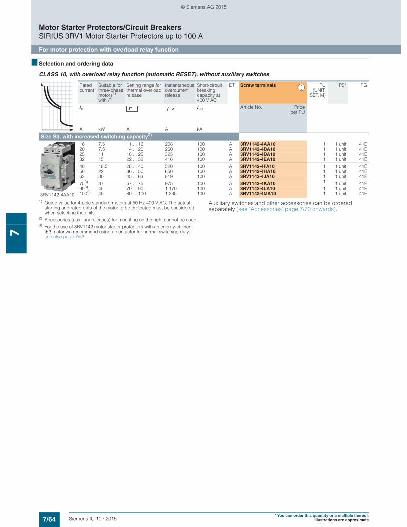
7/64 Siemens IC 10 · 2015* You can order this quantity or a multiple thereof.
Illustrations are approximate
Motor Starter Protectors/Circuit BreakersSIRIUS 3RV1 Motor Starter Protectors up to 100 A
For motor protection with overload relay function
7
■ Selection and ordering data
CLASS 10, with overload relay function (automatic RESET), without auxiliary switches
1) Guide value for 4-pole standard motors at 50 Hz 400 V AC. The actual starting and rated data of the motor to be protected must be considered when selecting the units.
2) Accessories (auxiliary releases) for mounting on the right cannot be used.3) For the use of 3RV1142 motor starter protectors with an energy-efficient
IE3 motor we recommend using a contactor for normal switching duty, see also page 7/53.
Auxiliary switches and other accessories can be ordered separately (see "Accessories" page 7/70 onwards).
Rated current
Suitable for three-phase motors1) with P
Setting range for thermal overload release
Instantaneous overcurrent release
Short-circuit breaking capacity at 400 V AC
DT Screw terminals PU(UNIT,
SET, M)
PS* PG
In Icu Article No. Priceper PU
A kW A A kA
Size S3, with increased switching capacity2)
3RV1142-4AA10
16 7.5 11 ... 16 208 100 A 3RV1142-4AA10 1 1 unit 41E20 7.5 14 ... 20 260 100 A 3RV1142-4BA10 1 1 unit 41E25 11 18 ... 25 325 100 A 3RV1142-4DA10 1 1 unit 41E32 15 22 ... 32 416 100 A 3RV1142-4EA10 1 1 unit 41E
40 18.5 28 ... 40 520 100 A 3RV1142-4FA10 1 1 unit 41E50 22 36 ... 50 650 100 A 3RV1142-4HA10 1 1 unit 41E63 30 45 ... 63 819 100 A 3RV1142-4JA10 1 1 unit 41E
753) 37 57 ... 75 975 100 A 3RV1142-4KA10 1 1 unit 41E903) 45 70 ... 90 1 170 100 A 3RV1142-4LA10 1 1 unit 41E1003) 45 80 ... 100 1 235 100 A 3RV1142-4MA10 1 1 unit 41E
© Siemens AG 2015
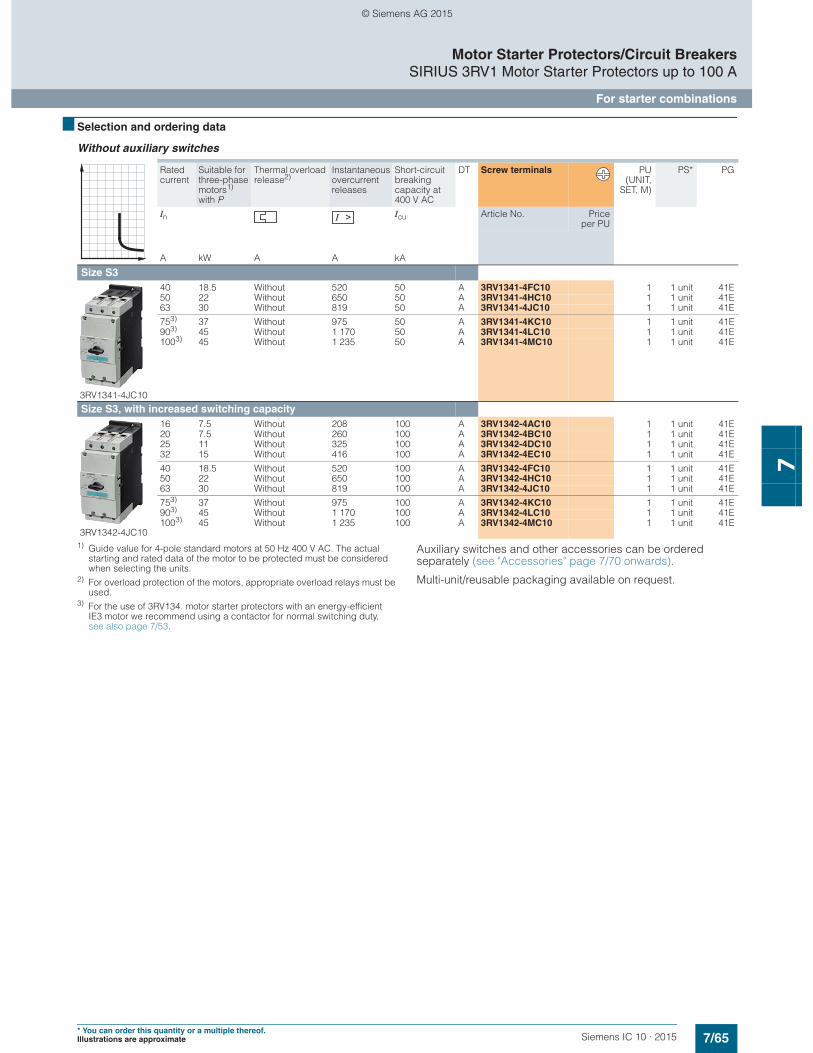
7/65Siemens IC 10 · 2015* You can order this quantity or a multiple thereof.Illustrations are approximate
Motor Starter Protectors/Circuit BreakersSIRIUS 3RV1 Motor Starter Protectors up to 100 A
For starter combinations
7
■ Selection and ordering data
Without auxiliary switches
1) Guide value for 4-pole standard motors at 50 Hz 400 V AC. The actual starting and rated data of the motor to be protected must be considered when selecting the units.
2) For overload protection of the motors, appropriate overload relays must be used.
3) For the use of 3RV134. motor starter protectors with an energy-efficient IE3 motor we recommend using a contactor for normal switching duty, see also page 7/53.
Auxiliary switches and other accessories can be ordered separately (see "Accessories" page 7/70 onwards).
Multi-unit/reusable packaging available on request.
Rated current
Suitable for three-phase motors1) with P
Thermal overload release2)
Instantaneous overcurrent releases
Short-circuit breaking capacity at 400 V AC
DT Screw terminals PU(UNIT,
SET, M)
PS* PG
In Icu Article No. Priceper PU
A kW A A kA
Size S3
3RV1341-4JC10
40 18.5 Without 520 50 A 3RV1341-4FC10 1 1 unit 41E50 22 Without 650 50 A 3RV1341-4HC10 1 1 unit 41E63 30 Without 819 50 A 3RV1341-4JC10 1 1 unit 41E
753) 37 Without 975 50 A 3RV1341-4KC10 1 1 unit 41E903) 45 Without 1 170 50 A 3RV1341-4LC10 1 1 unit 41E1003) 45 Without 1 235 50 A 3RV1341-4MC10 1 1 unit 41E
Size S3, with increased switching capacity
3RV1342-4JC10
16 7.5 Without 208 100 A 3RV1342-4AC10 1 1 unit 41E20 7.5 Without 260 100 A 3RV1342-4BC10 1 1 unit 41E25 11 Without 325 100 A 3RV1342-4DC10 1 1 unit 41E32 15 Without 416 100 A 3RV1342-4EC10 1 1 unit 41E
40 18.5 Without 520 100 A 3RV1342-4FC10 1 1 unit 41E50 22 Without 650 100 A 3RV1342-4HC10 1 1 unit 41E63 30 Without 819 100 A 3RV1342-4JC10 1 1 unit 41E
753) 37 Without 975 100 A 3RV1342-4KC10 1 1 unit 41E903) 45 Without 1 170 100 A 3RV1342-4LC10 1 1 unit 41E1003) 45 Without 1 235 100 A 3RV1342-4MC10 1 1 unit 41E
© Siemens AG 2015

7/66 Siemens IC 10 · 2015* You can order this quantity or a multiple thereof.
Illustrations are approximate
Motor Starter Protectors/Circuit BreakersSIRIUS 3RV1 Motor Starter Protectors up to 100 A
For fuse monitoring
7
■ Selection and ordering data
Without auxiliary switches
Note:
The auxiliary switch required for signaling must be ordered separately.
Multi-unit/reusable packaging available on request.
■ Accessories
Additional auxiliary switches and other accessories, see "Accessories" page 7/70 onwards.
Rated current Thermal overload releases
Instantaneous overcurrent release
Short-circuit breaking capacity at 400 V AC
DT Screw terminals PU(UNIT,
SET, M)
PS* PG
In Icu Article No. Priceper PU
A A A kA
Size S00
3RV1611-0BD10
0.2 0.2 1.2 100 } 3RV1611-0BD10 1 1 unit 41E
Version Contacts DT Screw terminals PU(UNIT,
SET, M)
PS* PG
Article No. Priceper PU
Mountable auxiliary switches (essential accessories)
3RV1901-1E
Transverse auxiliary switches With screw terminals, mountable on front
1 NO + 1 NC } 3RV1901-1E 1 1 unit 41E
3RV1901-1A
Lateral auxiliary switches With screw terminals, mountable on the left
1 NO + 1 NC } 3RV1901-1A 1 1 unit 41E
© Siemens AG 2015

7/67Siemens IC 10 · 2015* You can order this quantity or a multiple thereof.Illustrations are approximate
Motor Starter Protectors/Circuit BreakersSIRIUS 3RV1 Circuit Breakers up to 100 A
For system protection according to UL 489/CSA C22.2 No. 5
7
■ Selection and ordering data
Without auxiliary switches
Circuit breakers for system protection and non-motor loads according to UL/CSA
1) Rated value 100 % according to UL 489 and IEC 60947-2 ("100 % rated breaker").
2) Values for 600 Y/347 V AC, see page 7/57.
Transverse auxiliary switches must not be mounted, lateral auxiliary switches can be ordered separately (see "Accessories" page 7/70 onwards).
Rated current1)
Thermal overload releases (non-adjustable)
Instantaneous overcurrent release
Short-circuit breaking capacity at
DT Screw terminals PU(UNIT,
SET, M)
PS* PG
480 Y/277 V AC2) 480 V AC
In1) Ibc Ibc Article No. Price
per PU
A A A kA kA
Size S3
3RV1742-5FD10
10 10 150 65 65 B 3RV1742-5AD10 1 1 unit 41E15 15 225 65 65 B 3RV1742-5BD10 1 1 unit 41E
20 20 260 65 65 B 3RV1742-5CD10 1 1 unit 41E25 25 325 65 65 B 3RV1742-5DD10 1 1 unit 41E30 30 390 65 65 B 3RV1742-5ED10 1 1 unit 41E35 35 455 65 -- B 3RV1742-5FD10 1 1 unit 41E
40 40 520 65 -- B 3RV1742-5GD10 1 1 unit 41E45 45 585 65 -- B 3RV1742-5HD10 1 1 unit 41E50 50 650 65 -- B 3RV1742-5JD10 1 1 unit 41E
60 60 780 65 -- B 3RV1742-5LD10 1 1 unit 41E70 70 910 65 -- B 3RV1742-5QD10 1 1 unit 41E
© Siemens AG 2015
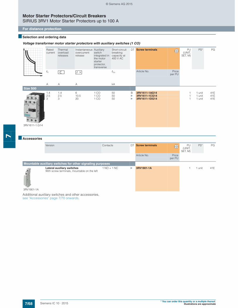
7/68 Siemens IC 10 · 2015* You can order this quantity or a multiple thereof.
Illustrations are approximate
Motor Starter Protectors/Circuit BreakersSIRIUS 3RV1 Motor Starter Protectors up to 100 A
For distance protection
7
■ Selection and ordering data
Voltage transformer motor starter protectors with auxiliary switches (1 CO)
■ Accessories
Additional auxiliary switches and other accessories, see "Accessories" page 7/70 onwards.
Rated current
Thermal overload releases
Instantaneous overcurrent release
Auxiliary switch integrated in the motor starter protector, transverse
Short-circuit breaking capacity at 400 V AC
DT Screw terminals PU(UNIT,
SET, M)
PS* PG
In Icu Article No. Priceper PU
A A A kA
Size S00
3RV1611-1.G14
1.4 1.4 6 1 CO 50 B 3RV1611-1AG14 1 1 unit 41E2.5 2.5 10.5 1 CO 50 } 3RV1611-1CG14 1 1 unit 41E3 3 20 1 CO 50 } 3RV1611-1DG14 1 1 unit 41E
Version Contacts DT Screw terminals PU(UNIT,
SET, M)
PS* PG
Article No. Priceper PU
Mountable auxiliary switches for other signaling purposes
3RV1901-1A
Lateral auxiliary switches With screw terminals, mountable on the left
1 NO + 1 NC } 3RV1901-1A 1 1 unit 41E
© Siemens AG 2015
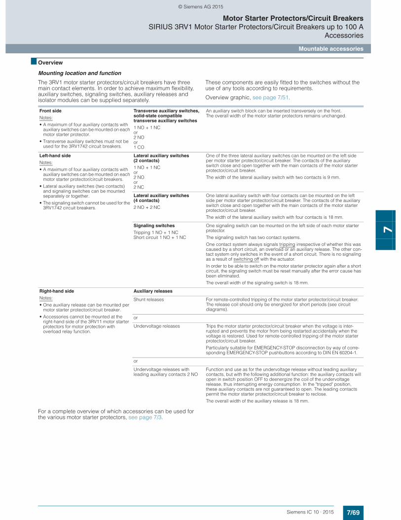
7/69Siemens IC 10 · 2015
Motor Starter Protectors/Circuit BreakersSIRIUS 3RV1 Motor Starter Protectors/Circuit Breakers up to 100 A
Accessories
Mountable accessories
7
■ Overview
Mounting location and function
The 3RV1 motor starter protectors/circuit breakers have three main contact elements. In order to achieve maximum flexibility, auxiliary switches, signaling switches, auxiliary releases and isolator modules can be supplied separately.
These components are easily fitted to the switches without the use of any tools according to requirements.
Overview graphic, see page 7/51.
For a complete overview of which accessories can be used for the various motor starter protectors, see page 7/3.
Front side
Notes:
• A maximum of four auxiliary contacts with auxiliary switches can be mounted on each motor starter protector.
• Transverse auxiliary switches must not be used for the 3RV1742 circuit breakers.
Transverse auxiliary switches, solid-state compatible transverse auxiliary switches
1 NO + 1 NCor2 NOor 1 CO
An auxiliary switch block can be inserted transversely on the front. The overall width of the motor starter protectors remains unchanged.
Left-hand side
Notes:
• A maximum of four auxiliary contacts with auxiliary switches can be mounted on each motor starter protector/circuit breakers.
• Lateral auxiliary switches (two contacts) and signaling switches can be mounted separately or together.
• The signaling switch cannot be used for the 3RV1742 circuit breakers.
Lateral auxiliary switches (2 contacts)
1 NO + 1 NCor2 NOor 2 NC
One of the three lateral auxiliary switches can be mounted on the left side per motor starter protector/circuit breaker. The contacts of the auxiliary switch close and open together with the main contacts of the motor starter protector/circuit breaker.
The width of the lateral auxiliary switch with two contacts is 9 mm.
Lateral auxiliary switches (4 contacts)
2 NO + 2 NC
One lateral auxiliary switch with four contacts can be mounted on the left side per motor starter protector/circuit breaker. The contacts of the auxiliary switch close and open together with the main contacts of the motor starter protector/circuit breaker.
The width of the lateral auxiliary switch with four contacts is 18 mm.
Signaling switches
Tripping 1 NO + 1 NCShort circuit 1 NO + 1 NC
One signaling switch can be mounted on the left side of each motor starter protector.
The signaling switch has two contact systems.
One contact system always signals tripping irrespective of whether this was caused by a short circuit, an overload or an auxiliary release. The other con-tact system only switches in the event of a short circuit. There is no signaling as a result of switching off with the actuator.
In order to be able to switch on the motor starter protector again after a short circuit, the signaling switch must be reset manually after the error cause has been eliminated.
The overall width of the signaling switch is 18 mm.
Right-hand side
Notes:
• One auxiliary release can be mounted per motor starter protector/circuit breaker.
• Accessories cannot be mounted at the right-hand side of the 3RV11 motor starter protectors for motor protection with overload relay function.
Auxiliary releases
Shunt releases For remote-controlled tripping of the motor starter protector/circuit breaker. The release coil should only be energized for short periods (see circuit diagrams).
or
Undervoltage releases Trips the motor starter protector/circuit breaker when the voltage is inter-rupted and prevents the motor from being restarted accidentally when the voltage is restored. Used for remote-controlled tripping of the motor starter protector/circuit breaker.
Particularly suitable for EMERGENCY-STOP disconnection by way of corre-sponding EMERGENCY-STOP pushbuttons according to DIN EN 60204-1.
or
Undervoltage releases with leading auxiliary contacts 2 NO
Function and use as for the undervoltage release without leading auxiliary contacts, but with the following additional function: the auxiliary contacts will open in switch position OFF to deenergize the coil of the undervoltage release, thus interrupting energy consumption. In the "tripped" position, these auxiliary contacts are not guaranteed to open. The leading contacts permit the motor starter protector/circuit breaker to reclose.
The overall width of the auxiliary release is 18 mm.
© Siemens AG 2015
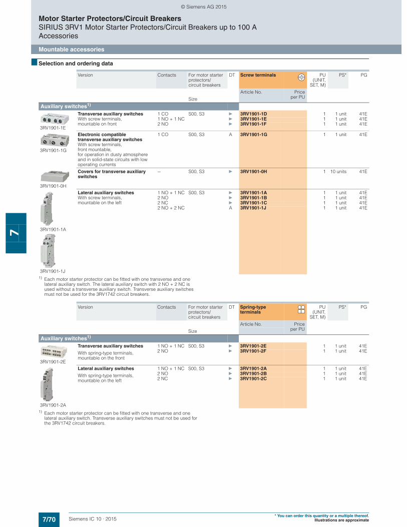
7/70 Siemens IC 10 · 2015* You can order this quantity or a multiple thereof.
Illustrations are approximate
Motor Starter Protectors/Circuit BreakersSIRIUS 3RV1 Motor Starter Protectors/Circuit Breakers up to 100 AAccessories
Mountable accessories
7
■ Selection and ordering data
1) Each motor starter protector can be fitted with one transverse and one lateral auxiliary switch. The lateral auxiliary switch with 2 NO + 2 NC is used without a transverse auxiliary switch. Transverse auxiliary switches must not be used for the 3RV1742 circuit breakers.
1) Each motor starter protector can be fitted with one transverse and one lateral auxiliary switch. Transverse auxiliary switches must not be used for the 3RV1742 circuit breakers.
Version Contacts For motor starter protectors/circuit breakers
DT Screw terminals PU(UNIT,
SET, M)
PS* PG
Article No. Priceper PUSize
Auxiliary switches1)
3RV1901-1E
Transverse auxiliary switches With screw terminals,mountable on front
1 CO S00, S3 } 3RV1901-1D 1 1 unit 41E1 NO + 1 NC } 3RV1901-1E 1 1 unit 41E2 NO } 3RV1901-1F 1 1 unit 41E
3RV1901-1G
Electronic compatible transverse auxiliary switches With screw terminals,front mountable,for operation in dusty atmosphere and in solid-state circuits with low operating currents
1 CO S00, S3 A 3RV1901-1G 1 1 unit 41E
3RV1901-0H
Covers for transverse auxiliary switches
-- S00, S3 } 3RV1901-0H 1 10 units 41E
3RV1901-1A
3RV1901-1J
Lateral auxiliary switches With screw terminals,mountable on the left
1 NO + 1 NC S00, S3 } 3RV1901-1A 1 1 unit 41E2 NO } 3RV1901-1B 1 1 unit 41E2 NC } 3RV1901-1C 1 1 unit 41E2 NO + 2 NC A 3RV1901-1J 1 1 unit 41E
Version Contacts For motor starter protectors/circuit breakers
DT Spring-type terminals
PU(UNIT,
SET, M)
PS* PG
Article No. Priceper PUSize
Auxiliary switches1)
3RV1901-2E
Transverse auxiliary switches 1 NO + 1 NC S00, S3 } 3RV1901-2E 1 1 unit 41E
With spring-type terminals, mountable on the front
2 NO } 3RV1901-2F 1 1 unit 41E
3RV1901-2A
Lateral auxiliary switches 1 NO + 1 NC S00, S3 } 3RV1901-2A 1 1 unit 41E
With spring-type terminals, mountable on the left
2 NO } 3RV1901-2B 1 1 unit 41E2 NC } 3RV1901-2C 1 1 unit 41E
© Siemens AG 2015
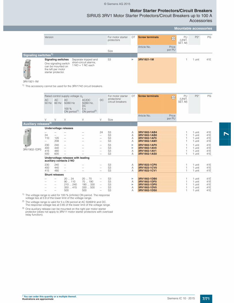
7/71Siemens IC 10 · 2015* You can order this quantity or a multiple thereof.Illustrations are approximate
Motor Starter Protectors/Circuit BreakersSIRIUS 3RV1 Motor Starter Protectors/Circuit Breakers up to 100 A
Accessories
Mountable accessories
7
1) This accessory cannot be used for the 3RV1742 circuit breakers.
1) The voltage range is valid for 100 % (infinite) ON period. The response voltage lies at 0.9 of the lower limit of the voltage range.
2) The voltage range is valid for 5 s ON period at AC 50/60Hz and DC. The response voltage lies at 0.85 of the lower limit of the voltage range.
3) One auxiliary release can be mounted on the right per motor starter protector (does not apply to 3RV11 motor starter protectors with overload relay function).
Version For motor starter protectors
DT Screw terminals PU(UNIT,
SET, M)
PS* PG
Article No. Priceper PUSize
Signaling switches1)
3RV1921-1M
Signaling switches
One signaling switch can be mounted on the left per motor starter protector.
Separate tripped and short-circuit alarms, 1 NO + 1 NC each
S3
} 3RV1921-1M 1 1 unit 41E
Rated control supply voltage Us For motor starter protectors/circuit breakers
DT Screw terminals PU(UNIT,
SET, M)
PS* PG
AC AC AC AC/DC DC50 Hz 60 Hz 50/60 Hz
100 % ON period1)
50/60 Hz, DC 5 s ON period2)
Article No. Priceper PUV V V V V Size
Auxiliary releases3)
3RV1902-1DP0
Undervoltage releases
-- -- -- -- 24 S3 A 3RV1902-1AB4 1 1 unit 41E24 -- -- -- -- S3 A 3RV1902-1AB0 1 1 unit 41E110 120 -- -- -- S3 A 3RV1902-1AF0 1 1 unit 41E-- 208 -- -- -- S3 A 3RV1902-1AM1 1 1 unit 41E
230 240 -- -- -- S3 } 3RV1902-1AP0 1 1 unit 41E400 440 -- -- -- S3 } 3RV1902-1AV0 1 1 unit 41E415 480 -- -- -- S3 A 3RV1902-1AV1 1 1 unit 41E500 600 -- -- -- S3 A 3RV1902-1AS0 1 1 unit 41E
Undervoltage releases with leading auxiliary contacts 2 NO
230 240 -- -- -- S3 A 3RV1922-1CP0 1 1 unit 41E400 440 -- -- -- S3 A 3RV1922-1CV0 1 1 unit 41E415 480 -- -- -- S3 A 3RV1922-1CV1 1 1 unit 41E
Shunt releases
-- -- 20 ... 24 20 ... 70 -- S3 } 3RV1902-1DB0 1 1 unit 41E-- -- 90 ... 110 70 ... 190 -- S3 A 3RV1902-1DF0 1 1 unit 41E-- -- 210 ... 240 190 ... 330 -- S3 } 3RV1902-1DP0 1 1 unit 41E-- -- 350 ... 415 330 ... 500 -- S3 A 3RV1902-1DV0 1 1 unit 41E-- -- 500 500 -- S3 A 3RV1902-1DS0 1 1 unit 41E
© Siemens AG 2015
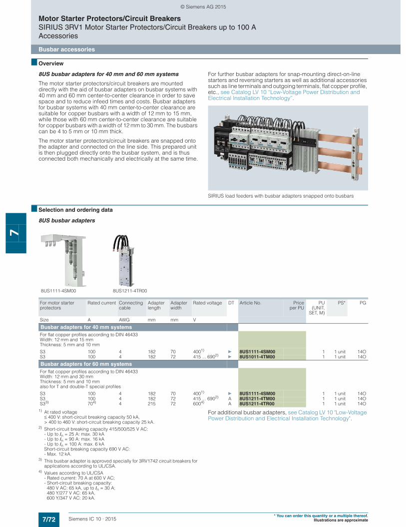
7/72 Siemens IC 10 · 2015* You can order this quantity or a multiple thereof.
Illustrations are approximate
Motor Starter Protectors/Circuit BreakersSIRIUS 3RV1 Motor Starter Protectors/Circuit Breakers up to 100 AAccessories
Busbar accessories
7
■ Overview
8US busbar adapters for 40 mm and 60 mm systems
The motor starter protectors/circuit breakers are mounted directly with the aid of busbar adapters on busbar systems with 40 mm and 60 mm center-to-center clearance in order to save space and to reduce infeed times and costs. Busbar adapters for busbar systems with 40 mm center-to-center clearance are suitable for copper busbars with a width of 12 mm to 15 mm, while those with 60 mm center-to-center clearance are suitable for copper busbars with a width of 12 mm to 30 mm. The busbars can be 4 to 5 mm or 10 mm thick.
The motor starter protectors/circuit breakers are snapped onto the adapter and connected on the line side. This prepared unit is then plugged directly onto the busbar system, and is thus connected both mechanically and electrically at the same time.
For further busbar adapters for snap-mounting direct-on-line starters and reversing starters as well as additional accessories such as line terminals and outgoing terminals, flat copper profile, etc., see Catalog LV 10 “Low-Voltage Power Distribution and Electrical Installation Technology”.
SIRIUS load feeders with busbar adapters snapped onto busbars
■ Selection and ordering data
8US busbar adapters
1) At rated voltage≤ 400 V: short-circuit breaking capacity 50 kA, > 400 to 460 V: short-circuit breaking capacity 25 kA.
2) Short-circuit breaking capacity 415/500/525 V AC:- Up to In = 25 A: max. 30 kA- Up to In = 90 A: max. 16 kA- Up to In = 100 A: max. 6 kAShort-circuit breaking capacity 690 V AC:- Max. 12 kA.
3) This busbar adapter is approved specially for 3RV1742 circuit breakers for applications according to UL/CSA.
4) Values according to UL/CSA- Rated current: 70 A at 600 V AC;- Short-circuit breaking capacity: 480 V AC: 65 kA, up to In = 30 A; 480 Y/277 V AC: 65 kA, 600 Y/347 V AC: 20 kA.
For additional busbar adapters, see Catalog LV 10 "Low-Voltage Power Distribution and Electrical Installation Technology".
For motor starter protectors
Rated current Connecting cable
Adapter length
Adapter width
Rated voltage DT Article No. Priceper PU
PU(UNIT,
SET, M)
PS* PG
Size A AWG mm mm V
Busbar adapters for 40 mm systemsFor flat copper profiles according to DIN 46433 Width: 12 mm and 15 mm Thickness: 5 mm and 10 mm
S3 100 4 182 70 4001)} 8US1111-4SM00 1 1 unit 14O
S3 100 4 182 72 415 ... 6902)} 8US1011-4TM00 1 1 unit 14O
Busbar adapters for 60 mm systemsFor flat copper profiles according to DIN 46433 Width: 12 mm and 30 mm Thickness: 5 mm and 10 mm also for T and double-T special profiles
S3 100 4 182 70 4001)} 8US1111-4SM00 1 1 unit 14O
S3 100 4 182 72 415 ... 6902) A 8US1211-4TM00 1 1 unit 14OS33) 704) 4 215 72 6004) A 8US1211-4TR00 1 1 unit 14O
8US1111-4SM00 8US1211-4TR00
© Siemens AG 2015
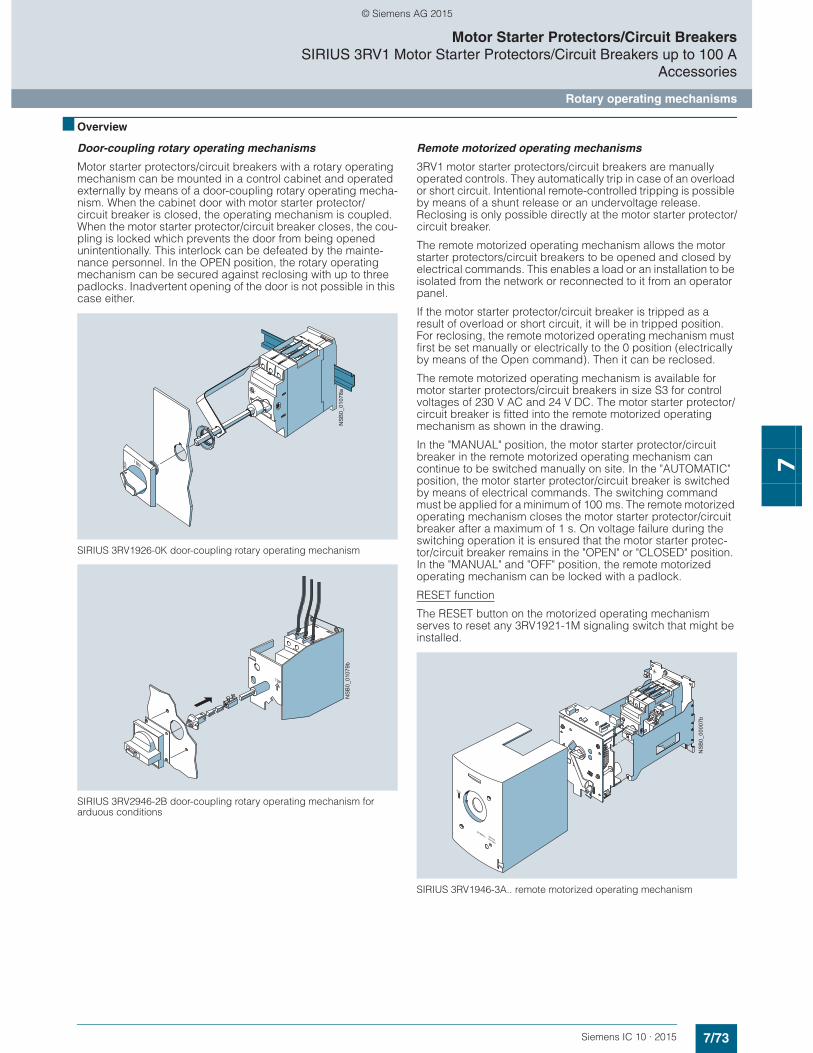
7/73Siemens IC 10 · 2015
Motor Starter Protectors/Circuit BreakersSIRIUS 3RV1 Motor Starter Protectors/Circuit Breakers up to 100 A
Accessories
Rotary operating mechanisms
7
■ Overview
Door-coupling rotary operating mechanisms
Motor starter protectors/circuit breakers with a rotary operating mechanism can be mounted in a control cabinet and operated externally by means of a door-coupling rotary operating mecha-nism. When the cabinet door with motor starter protector/circuit breaker is closed, the operating mechanism is coupled. When the motor starter protector/circuit breaker closes, the cou-pling is locked which prevents the door from being opened unintentionally. This interlock can be defeated by the mainte-nance personnel. In the OPEN position, the rotary operating mechanism can be secured against reclosing with up to three padlocks. Inadvertent opening of the door is not possible in this case either.
SIRIUS 3RV1926-0K door-coupling rotary operating mechanism
SIRIUS 3RV2946-2B door-coupling rotary operating mechanism for arduous conditions
Remote motorized operating mechanisms
3RV1 motor starter protectors/circuit breakers are manually operated controls. They automatically trip in case of an overload or short circuit. Intentional remote-controlled tripping is possible by means of a shunt release or an undervoltage release. Reclosing is only possible directly at the motor starter protector/circuit breaker.
The remote motorized operating mechanism allows the motor starter protectors/circuit breakers to be opened and closed by electrical commands. This enables a load or an installation to be isolated from the network or reconnected to it from an operator panel.
If the motor starter protector/circuit breaker is tripped as a result of overload or short circuit, it will be in tripped position. For reclosing, the remote motorized operating mechanism must first be set manually or electrically to the 0 position (electrically by means of the Open command). Then it can be reclosed.
The remote motorized operating mechanism is available for motor starter protectors/circuit breakers in size S3 for control voltages of 230 V AC and 24 V DC. The motor starter protector/circuit breaker is fitted into the remote motorized operating mechanism as shown in the drawing.
In the "MANUAL" position, the motor starter protector/circuit breaker in the remote motorized operating mechanism can continue to be switched manually on site. In the "AUTOMATIC" position, the motor starter protector/circuit breaker is switched by means of electrical commands. The switching command must be applied for a minimum of 100 ms. The remote motorized operating mechanism closes the motor starter protector/circuit breaker after a maximum of 1 s. On voltage failure during the switching operation it is ensured that the motor starter protec-tor/circuit breaker remains in the "OPEN" or "CLOSED" position. In the "MANUAL" and "OFF" position, the remote motorized operating mechanism can be locked with a padlock.
RESET function
The RESET button on the motorized operating mechanism serves to reset any 3RV1921-1M signaling switch that might be installed.
SIRIUS 3RV1946-3A.. remote motorized operating mechanism
NS
B0_
0107
8aN
SB
0_01
079b
NS
B0_
0000
7b
© Siemens AG 2015
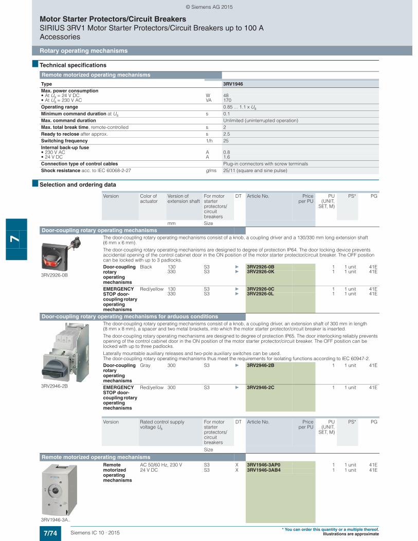
7/74 Siemens IC 10 · 2015* You can order this quantity or a multiple thereof.
Illustrations are approximate
Motor Starter Protectors/Circuit BreakersSIRIUS 3RV1 Motor Starter Protectors/Circuit Breakers up to 100 AAccessories
Rotary operating mechanisms
7
■ Technical specifications
■ Selection and ordering data
Remote motorized operating mechanisms
Type 3RV1946Max. power consumption• At Us = 24 V DC W 48• At Us = 230 V AC VA 170Operating range 0.85 ... 1.1 x UsMinimum command duration at Us s 0.1Max. command duration Unlimited (uninterrupted operation)Max. total break time, remote-controlled s 2Ready to reclose after approx. s 2.5Switching frequency 1/h 25Internal back-up fuse• 230 V AC A 0.8• 24 V DC A 1.6Connection type of control cables Plug-in connectors with screw terminalsShock resistance acc. to IEC 60068-2-27 g/ms 25/11 (square and sine pulse)
Version Color of actuator
Version of extension shaft
For motor starter protectors/circuit breakers
DT Article No. Priceper PU
PU(UNIT,
SET, M)
PS* PG
mm Size
Door-coupling rotary operating mechanisms
3RV2926-0B
The door-coupling rotary operating mechanisms consist of a knob, a coupling driver and a 130/330 mm long extension shaft (6 mm x 6 mm).
The door-coupling rotary operating mechanisms are designed to degree of protection IP64. The door locking device prevents accidental opening of the control cabinet door in the ON position of the motor starter protector/circuit breaker. The OFF position can be locked with up to 3 padlocks.Door-coupling rotary operating mechanisms
Black 130 S3 } 3RV2926-0B 1 1 unit 41E330 S3 } 3RV2926-0K 1 1 unit 41E
EMERGENCY STOP door-coupling rotary operating mechanisms
Red/yellow 130 S3 } 3RV2926-0C 1 1 unit 41E330 S3 } 3RV2926-0L 1 1 unit 41E
Door-coupling rotary operating mechanisms for arduous conditions
3RV2946-2B
The door-coupling rotary operating mechanisms consist of a knob, a coupling driver, an extension shaft of 300 mm in length (8 mm x 8 mm), a spacer and two metal brackets, into which the motor starter protector/circuit breaker is inserted.
The door-coupling rotary operating mechanisms are designed to degree of protection IP65. The door interlocking reliably prevents opening of the control cabinet door in the ON position of the motor starter protector/circuit breaker. The OFF position can be locked with up to three padlocks.
Laterally mountable auxiliary releases and two-pole auxiliary switches can be used. The door-coupling rotary operating mechanisms thus meet the requirements for isolating functions according to IEC 60947-2.Door-coupling rotary operating mechanisms
Gray 300 S3 } 3RV2946-2B 1 1 unit 41E
EMERGENCY STOP door-coupling rotary operating mechanisms
Red/yellow 300 S3 } 3RV2946-2C 1 1 unit 41E
Version Rated control supplyvoltage Us
For motor starter protectors/circuit breakers
DT Article No. Priceper PU
PU(UNIT,
SET, M)
PS* PG
Size
Remote motorized operating mechanisms
3RV1946-3A..
Remote motorized operating mechanisms
AC 50/60 Hz, 230 V S3 X 3RV1946-3AP0 1 1 unit 41E24 V DC S3 X 3RV1946-3AB4 1 1 unit 41E
© Siemens AG 2015

7/75Siemens IC 10 · 2015* You can order this quantity or a multiple thereof.Illustrations are approximate
Motor Starter Protectors/Circuit BreakersSIRIUS 3RV1 Motor Starter Protectors/Circuit Breakers up to 100 A
Accessories
Mounting accessories
7
■ Overview
Terminal blocks for "Self-Protected Combination Motor Controllers (Type E)" according to UL 508/UL 60947-4-1
The 3RV10 motor starter protector/circuit breakers in size S3 are approved according to UL 508/UL 60947-4-1 as "Self-Protected Combination Motor Controllers" (Type E).
This requires increased clearance and creepage distances (1 inch and 2 inches respectively) at the input side of the device, which are achieved by replacing the standard box terminal with the 3RT1946-4GA07 terminal block.
Terminal block (Type E) SIRIUS 3RT1946-4GA07
According to CSA, the terminal blocks can be omitted when the device is used as a "Self-Protected Combination Motor Controller" (Type E).
■ Selection and ordering data
Accessories
NS
B0_
0138
0c
Version For motor starter protectors/circuit breakers
DT Article No. Priceper PU
PU(UNIT,
SET, M)
PS* PG
Size
Covers
Terminal covers for box terminalsAdditional touch protection to be fitted at the box terminals (2 units mountable per device)
S3 } 3RT1946-4EA2 1 1 unit 41B
Terminal covers For cable lug and busbar connection for maintain-ing the required voltage clearances and as touch protection if box terminal is removed (2 units can be mounted per motor starter protector/circuit breaker)
S3 B 3RT1946-4EA1 1 1 unit 41B
3RV1 (size S3) with 3RT1946-4EA1 (left) 3RV1908-0P (right)
Scale coversSealable, for covering the set current scale
S3 } 3RV1908-0P 100 10 units 41E
Fixing accessories
3RB1900-0B
Push-in lugsFor screwing the motor starter protector onto mounting plates
For each motor starter protector, two units are required.
S00 A 3RB1900-0B 100 10 units 41F
Terminal blocks for "Self-Protected Combination Motor Controllers (Type E)" according to UL 508/UL 60497-4-1
3RT1946-4GA07
Note:
UL 508/UL 60947-4-1 approval demands 1-inch clearance and 2-inch creepage distance for "Combination Motor Controllers Type E". The following terminal blocks must be used therefore in 3RV10 motor starter protector size S3.
The terminal blocks are not required for use according to CSA.
With size S3, these terminal blocks cannot be used in combination with a transverse auxiliary switch.
Terminal block type Efor extended clearance and creepage distances (1 and 2 inch)
S3 B 3RT1946-4GA07 1 1 unit 41B
Auxiliary terminals, 3-pole
3RT1946-4F
For connection of auxiliary and control cables to the main conductor connections (for one side)
S3 B 3RT1946-4F 1 1 unit 41B
© Siemens AG 2015
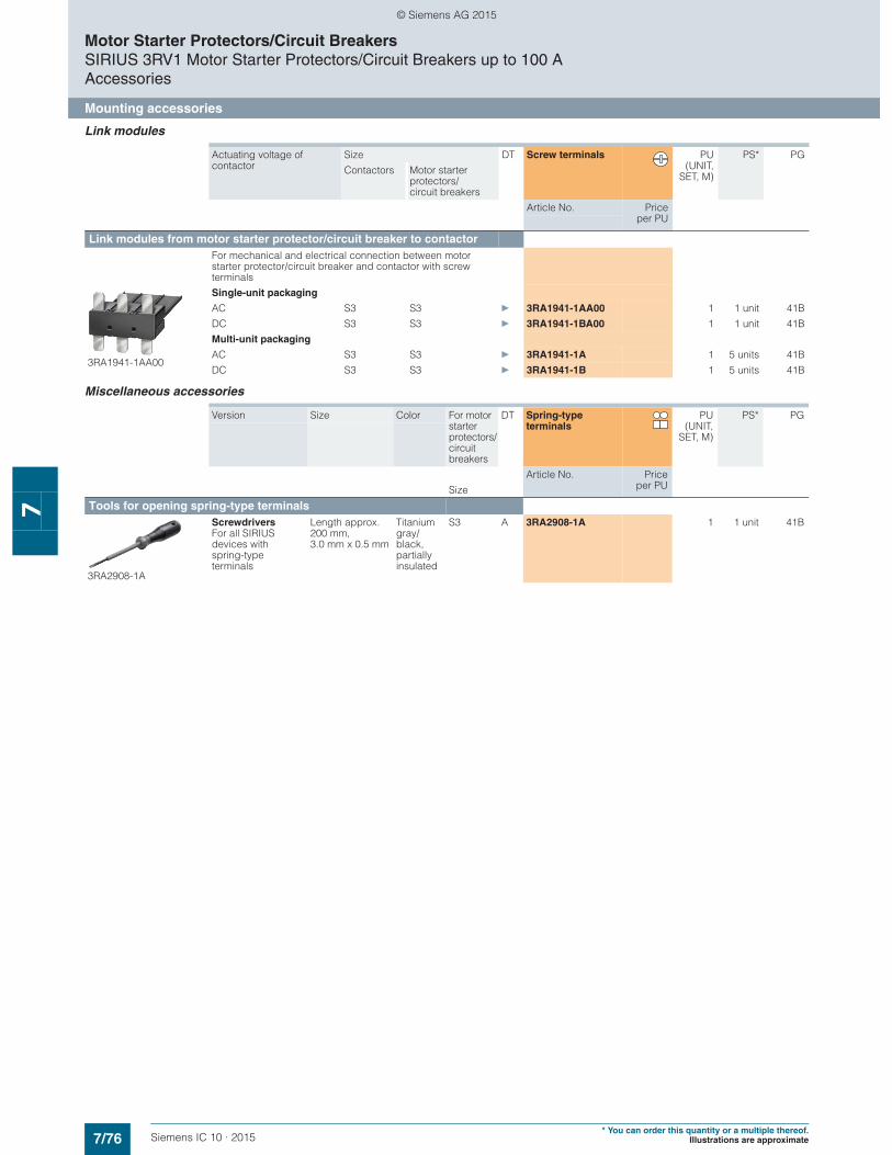
7/76 Siemens IC 10 · 2015* You can order this quantity or a multiple thereof.
Illustrations are approximate
Motor Starter Protectors/Circuit BreakersSIRIUS 3RV1 Motor Starter Protectors/Circuit Breakers up to 100 AAccessories
Mounting accessories
7
Link modules
Miscellaneous accessories
Actuating voltage of contactor
Size DT Screw terminals PU(UNIT,
SET, M)
PS* PG
Contactors Motor starter protectors/circuit breakers
Article No. Priceper PU
Link modules from motor starter protector/circuit breaker to contactor For mechanical and electrical connection between motor starter protector/circuit breaker and contactor with screw terminals
3RA1941-1AA00
Single-unit packaging
AC S3 S3 } 3RA1941-1AA00 1 1 unit 41B
DC S3 S3 } 3RA1941-1BA00 1 1 unit 41B
Multi-unit packaging
AC S3 S3 } 3RA1941-1A 1 5 units 41B
DC S3 S3 } 3RA1941-1B 1 5 units 41B
Version Size Color For motor starter protectors/circuit breakers
DT Spring-type terminals
PU(UNIT,
SET, M)
PS* PG
Article No. Priceper PUSize
Tools for opening spring-type terminals
3RA2908-1A
Screwdrivers For all SIRIUS devices with spring-type terminals
Length approx. 200 mm, 3.0 mm x 0.5 mm
Titanium gray/black, partially insulated
S3 A 3RA2908-1A 1 1 unit 41B
© Siemens AG 2015

7/77Siemens IC 10 · 2015* You can order this quantity or a multiple thereof.Illustrations are approximate
Motor Starter Protectors/Circuit BreakersSIRIUS 3RV1 Motor Starter Protectors/Circuit Breakers up to 100 A
Accessories
Front plates
7
■ Overview
Front plates
Motor starter protectors are frequently required to be actuated in any enclosure. Front plates equipped with a rotary operating mechanism for 3RV1.4. motor starter protectors/circuit breakers are available for this purpose.
Front plate for size S3
■ Selection and ordering data
NS
B0_
0219
4a
Version Degree of protection
For motor starter protectors
DT Article No. Priceper PU
PU(UNIT,
SET, M)
PS* PG
Size
Front plates
3RV1923-4B
Molded-plastic front plates with rotary operating mechanism, lockable in 0 position
For actuation of 3RV1 motor starter protectors in any enclosure
IP55 (front side)
S3 } 3RV1923-4B 1 1 unit 41E
Molded-plastic front plates with EMERGENCY-STOP rotary operating mechanism, red/yellow,lockable in 0 position
EMERGENCY-STOP actuation of 3RV1 motor starter protectors in any enclosure
IP55 (front side)
S3 A 3RV1923-4E 1 1 unit 41E
Version Rated control supply voltage Us
For motor starter protectors
DT Article No. Priceper PU
PU(UNIT,
SET, M)
PS* PG
V Size
Indicator lights
3RV1903-5B
Indicator lights For all enclosures and front plates
• With LED lamp for versions 110 ... 120 V, with glow lamp for versions 220 ... 500 V
• With colored lenses red, green, yellow, orange and clear
110 ... 120 S3 C 3RV1903-5B 1 1 unit 41E220 ... 240 C 3RV1903-5C 1 1 unit 41E380 ... 415 C 3RV1903-5E 1 1 unit 41E480 ... 500 C 3RV1903-5G 1 1 unit 41E
© Siemens AG 2015
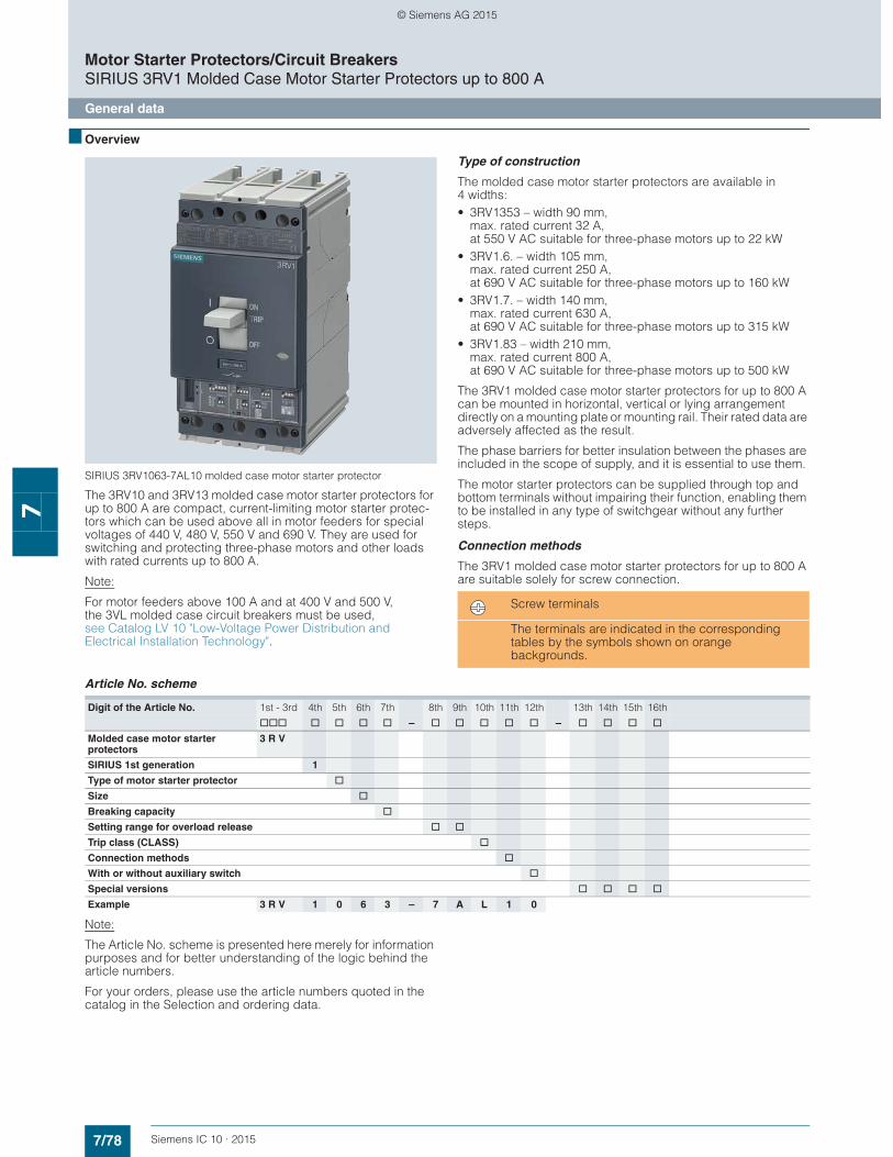
7/78 Siemens IC 10 · 2015
Motor Starter Protectors/Circuit BreakersSIRIUS 3RV1 Molded Case Motor Starter Protectors up to 800 A
General data
7
■ Overview
SIRIUS 3RV1063-7AL10 molded case motor starter protector
The 3RV10 and 3RV13 molded case motor starter protectors for up to 800 A are compact, current-limiting motor starter protec-tors which can be used above all in motor feeders for special voltages of 440 V, 480 V, 550 V and 690 V. They are used for switching and protecting three-phase motors and other loads with rated currents up to 800 A.
Note:
For motor feeders above 100 A and at 400 V and 500 V, the 3VL molded case circuit breakers must be used, see Catalog LV 10 "Low-Voltage Power Distribution and Electrical Installation Technology".
Type of construction
The molded case motor starter protectors are available in 4 widths:• 3RV1353 – width 90 mm,
max. rated current 32 A,at 550 V AC suitable for three-phase motors up to 22 kW
• 3RV1.6. – width 105 mm, max. rated current 250 A,at 690 V AC suitable for three-phase motors up to 160 kW
• 3RV1.7. – width 140 mm, max. rated current 630 A,at 690 V AC suitable for three-phase motors up to 315 kW
• 3RV1.83 – width 210 mm, max. rated current 800 A,at 690 V AC suitable for three-phase motors up to 500 kW
The 3RV1 molded case motor starter protectors for up to 800 A can be mounted in horizontal, vertical or lying arrangement directly on a mounting plate or mounting rail. Their rated data are adversely affected as the result.
The phase barriers for better insulation between the phases are included in the scope of supply, and it is essential to use them.
The motor starter protectors can be supplied through top and bottom terminals without impairing their function, enabling them to be installed in any type of switchgear without any further steps.
Connection methods
The 3RV1 molded case motor starter protectors for up to 800 A are suitable solely for screw connection..
Article No. scheme
Note:
The Article No. scheme is presented here merely for information purposes and for better understanding of the logic behind the article numbers.
For your orders, please use the article numbers quoted in the catalog in the Selection and ordering data.
Screw terminals
The terminals are indicated in the corresponding tables by the symbols shown on orange backgrounds.
Digit of the Article No. 1st - 3rd 4th 5th 6th 7th 8th 9th 10th 11th 12th 13th 14th 15th 16th
@@@ @ @ @ @ – @ @ @ @ @ – @ @ @ @
Molded case motor starter protectors
3 R V
SIRIUS 1st generation 1
Type of motor starter protector @
Size @
Breaking capacity @
Setting range for overload release @ @
Trip class (CLASS) @
Connection methods @
With or without auxiliary switch @
Special versions @ @ @ @
Example 3 R V 1 0 6 3 – 7 A L 1 0
© Siemens AG 2015
7/79Siemens IC 10 · 2015
Motor Starter Protectors/Circuit BreakersSIRIUS 3RV1 Molded Case Motor Starter Protectors up to 800 A
General data
7
■ Benefits
• High short-circuit breaking capacity in the feeder • Optimum usability in motor feeders for the special voltages
440 V, 480 V, 550 V and 690 V• Compact design
• The releases are available both in purely magnetic (up to 32 A) and in solid-state versions (100 A to 800 A)
• Available for motor or starter protection (short-circuit protection alone)
■ Application
Operating conditions
The 3RV1 molded case motor starter protectors for up to 800 A can be operated at ambient temperatures between -25 °C and +70 °C. They can be used according to IEC 60721-2-1 in the most difficult environmental conditions with a hot and damp climate.
Since operational currents, starting currents and current peaks are different even for motors with identical power ratings due to the inrush current, the motor ratings in the selection tables are only guide values. The specific rated and start up data of the motor to be protected is always paramount to the choice of the most suitable molded case motor starter protectors.
The 3RV1 molded case motor starter protectors up to 800 A have not been tested for use with frequency converters. The possibility of premature tripping in such applications cannot therefore be ruled out.
Possible uses
The 3RV1 molded case motor starter protectors for up to 800 A are suitable as switching and protection devices for motors. The following versions are available:• For motor protection;
the overload and short-circuit releases are designed for optimized protection and direct-on-line starting of induction squirrel-cage motors. The motor starter protectors have an electronic release which not only provides short-circuit and overload protection but is also sensitive to phase failure and phase unbalance and offers protection in the event of rotor blockage.
• For starter combinations; these molded case motor starter protectors are used for short-circuit protection in combinations of circuit breaker, motor contactor and overload relay. They are equipped with a purely magnetic release (up to 32 A) or a solid-state release (100 A to 800 A).
Standards and specifications
The electronic releases for motor protection comply with IEC 60947-4-1. Isolating features are also compliant with IEC 60947-2.
The 3RV1 molded case motor starter protectors comply in addition with IEC 60068-2-6 (shock and vibration strength) and are certified for the specifications of the most important marine classification societies: • RINA • Det Norske Veritas• Bureau Veritas• Lloyds Register of Shipping• Germanischer Lloyd• American Bureau of Shipping
© Siemens AG 2015

7/80 Siemens IC 10 · 2015
Motor Starter Protectors/Circuit BreakersSIRIUS 3RV1 Molded Case Motor Starter Protectors up to 800 A
General data
7
■ Technical specifications
✓ Has this function
-- Does not have this function
1) Value applies for 3RV1373-7GN10 molded case motor starter protectors.2) Value applies for 3RV1373-7JN10 molded case motor starter protectors.3) For overload protection of the motors, appropriate overload relays must be
used.4) From 50 °C, please note derating, see "Reference Manual
"Protection Equipment – Circuit Breakers · Molded Case Circuit Breakers", http://support.automation.siemens.com/WW/view/en/35681600.
General data
Type
Dimensions
3RV1063 3RV1073 3RV1083 3RV1353 3RV1363 3RV1364 3RV1373 3RV1374 3RV1383
• W• H• D
mmmmmm
105205139
140205139
210268159
90130102
105205139
105205139
140205139
140205139
210268159
Standard IEC 60947-2, EN 60947-2
Motor protection ✓ --
Starter combinations -- ✓
Rated current In A 160 400 630 160 250 400, 630 630, 800
Number of poles 3
Rated operational voltage Ue 50 ... 60 Hz AC V 690
Rated impulse withstand voltage Uimp V 8
Rated insulation voltage Ui V 1 000 800 1 000
Test voltage at industrial frequency for 1 min
V 3 500 3 000 3 500
Rated ultimate short-circuit breaking capacity Icu
• At 220/230 V AC, 50 ... 60 Hz kA 200 120 200
• At 380/415 V AC, 50 ... 60 Hz kA 120 100 85 120 200 120 200 100
• At 440 V AC, 50 ... 60 Hz kA 100 80 75 100 180 100 180 80
• At 500 V AC, 50 ... 60 Hz kA 85 65 50 85 150 85 150 65
• At 550 V AC, 50 ... 60 Hz kA -- 35 --
• At 690 V AC, 50 ... 60 Hz kA 70 30 10 70 80 70 80 30
Rated service short-circuit breaking capacity Ics (% of Icu)
• At 220/230 V AC, 50 ... 60 Hz % 100 75 100 75
• At 380/415 V AC, 50 ... 60 Hz % 100 75 100 75
• At 440 V AC, 50 ... 60 Hz % 100 75 100 75
• At 500 V AC, 50 ... 60 Hz % 100 75 100 1001)/752)
100 75
• At 690 V AC, 50 ... 60 Hz % 100 75 100 1001)/502)
100 75
Rated short-circuit making capacity (415 V) kA 264 220 187 264 440 264 440 220
Break time (415 V at Icu) ms 5 6 7 3 5 6 7
Category (IEC 60947-2) A B (400 A), A (630 A)
B A B (400 A),A (630 A)
B
Isolating features ✓
Trip class CLASS 10A, 10, 20, 30 --
Releases
• Magnetic type -- ✓ --
• Electronic (motor protection) ✓ --3)
• Electronic (starter combinations) -- ✓
Permissible ambient temperature
• Operation °C -25 ... +704)
• Storage °C -40 ... +70
Mechanical endurance
• Operating cycles 20 000 25 000 20 000
• Operating cycles per hour 240 120 240 120
Electrical endurance
• Operating cycles 8 000 7 000 5 000 8 000 7 000 5 000
• Operating cycles per hour (415 V AC) 120 60 120 60
W
H
D
© Siemens AG 2015
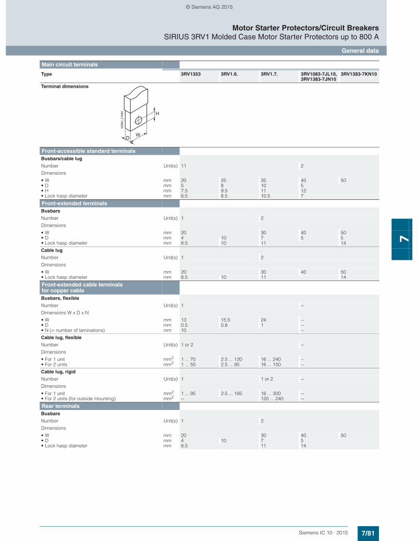
7/81Siemens IC 10 · 2015
Motor Starter Protectors/Circuit BreakersSIRIUS 3RV1 Molded Case Motor Starter Protectors up to 800 A
General data
7
Main circuit terminals
Type 3RV1353 3RV1.6. 3RV1.7. 3RV1083-7JL10, 3RV1383-7JN10
3RV1383-7KN10
Terminal dimensions
Front-accessible standard terminalsBusbars/cable lug
Number Unit(s) 11 2
Dimensions
• W mm 20 25 35 40 50• D mm 5 8 10 5• H mm 7.5 9.5 11 12• Lock hasp diameter mm 6.5 8.5 10.5 7
Front-extended terminalsBusbars
Number Unit(s) 1 2
Dimensions
• W mm 20 30 40 50• D mm 4 10 7 5 5• Lock hasp diameter mm 8.5 10 11 14
Cable lug
Number Unit(s) 1 2
Dimensions
• W mm 20 30 40 50• Lock hasp diameter mm 8.5 10 11 14
Front-extended cable terminalsfor copper cableBusbars, flexible
Number Unit(s) 1 --
Dimensions W x D x N
• W mm 13 15.5 24 --• D mm 0.5 0.8 1 --• N (= number of laminations) mm 10 --
Cable lug, flexible
Number Unit(s) 1 or 2 --
Dimensions
• For 1 unit mm2 1 ... 70 2.5 ... 120 16 ... 240 --• For 2 units mm2 1 ... 50 2.5 ... 95 16 ... 150 --
Cable lug, rigid
Number Unit(s) 1 1 or 2 --
Dimensions
• For 1 unit mm2 1 ... 95 2.5 ... 185 16 ... 300 --• For 2 units (for outside mounting) mm2 -- 120 ... 240 --
Rear terminalsBusbars
Number Unit(s) 1 2
Dimensions
• W mm 20 30 40 50• D mm 4 10 7 5• Lock hasp diameter mm 8.5 11 14
H
WD
NS
B0_
0198
0
© Siemens AG 2015
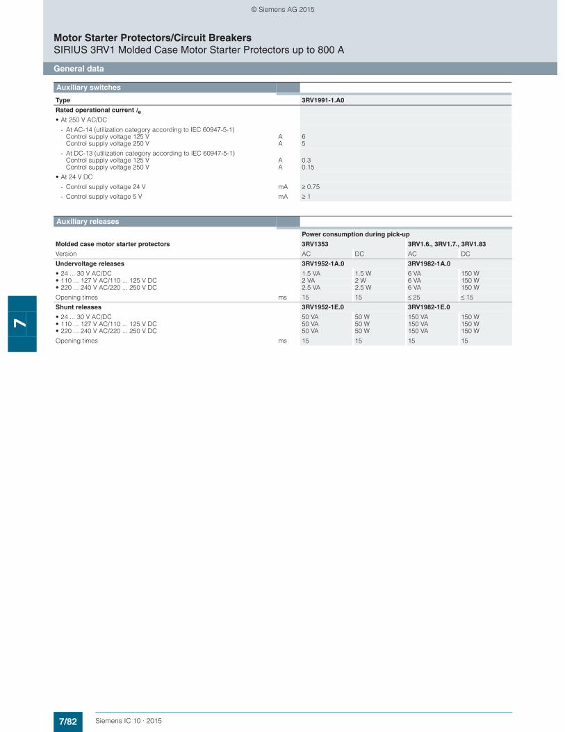
7/82 Siemens IC 10 · 2015
Motor Starter Protectors/Circuit BreakersSIRIUS 3RV1 Molded Case Motor Starter Protectors up to 800 A
General data
7
Auxiliary switches
Type 3RV1991-1.A0
Rated operational current Ie
• At 250 V AC/DC
- At AC-14 (utilization category according to IEC 60947-5-1) Control supply voltage 125 V Control supply voltage 250 V
AA
65
- At DC-13 (utilization category according to IEC 60947-5-1) Control supply voltage 125 V Control supply voltage 250 V
AA
0.30.15
• At 24 V DC
- Control supply voltage 24 V mA ≥ 0.75
- Control supply voltage 5 V mA ≥ 1
Auxiliary releases
Power consumption during pick-up
Molded case motor starter protectors 3RV1353 3RV1.6., 3RV1.7., 3RV1.83
Version AC DC AC DC
Undervoltage releases 3RV1952-1A.0 3RV1982-1A.0
• 24 ... 30 V AC/DC 1.5 VA 1.5 W 6 VA 150 W• 110 ... 127 V AC/110 ... 125 V DC 2 VA 2 W 6 VA 150 W• 220 ... 240 V AC/220 ... 250 V DC 2.5 VA 2.5 W 6 VA 150 W
Opening times ms 15 15 ≤ 25 ≤ 15
Shunt releases 3RV1952-1E.0 3RV1982-1E.0
• 24 ... 30 V AC/DC 50 VA 50 W 150 VA 150 W• 110 ... 127 V AC/110 ... 125 V DC 50 VA 50 W 150 VA 150 W• 220 ... 240 V AC/220 ... 250 V DC 50 VA 50 W 150 VA 150 W
Opening times ms 15 15 15 15
© Siemens AG 2015
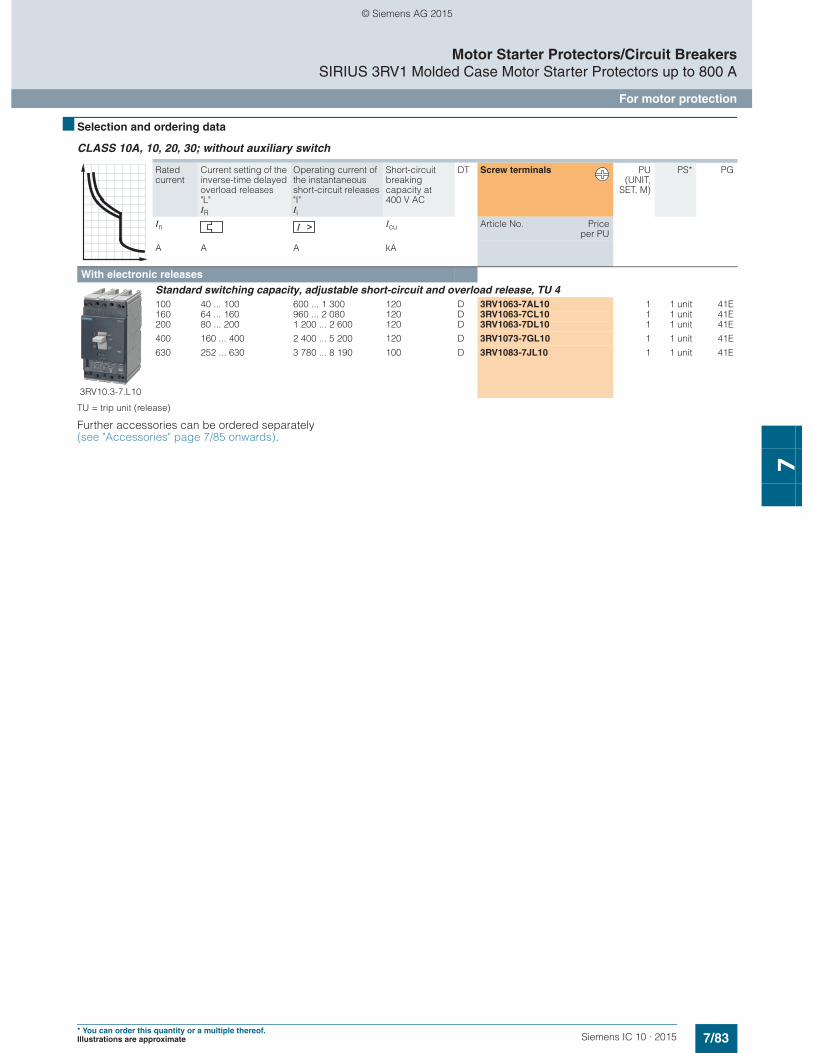
7/83Siemens IC 10 · 2015* You can order this quantity or a multiple thereof.Illustrations are approximate
Motor Starter Protectors/Circuit BreakersSIRIUS 3RV1 Molded Case Motor Starter Protectors up to 800 A
For motor protection
7
■ Selection and ordering data
CLASS 10A, 10, 20, 30; without auxiliary switch
TU = trip unit (release)
Further accessories can be ordered separately (see "Accessories" page 7/85 onwards).
Rated current
Current setting of the inverse-time delayed overload releases "L"IR
Operating current of the instantaneous short-circuit releases "I" Ii
Short-circuit breaking capacity at 400 V AC
DT Screw terminals PU(UNIT,
SET, M)
PS* PG
In Icu Article No. Priceper PU
A A A kA
With electronic releases
3RV10.3-7.L10
Standard switching capacity, adjustable short-circuit and overload release, TU 4100 40 ... 100 600 ... 1 300 120 D 3RV1063-7AL10 1 1 unit 41E160 64 ... 160 960 ... 2 080 120 D 3RV1063-7CL10 1 1 unit 41E200 80 ... 200 1 200 ... 2 600 120 D 3RV1063-7DL10 1 1 unit 41E
400 160 ... 400 2 400 ... 5 200 120 D 3RV1073-7GL10 1 1 unit 41E
630 252 ... 630 3 780 ... 8 190 100 D 3RV1083-7JL10 1 1 unit 41E
© Siemens AG 2015
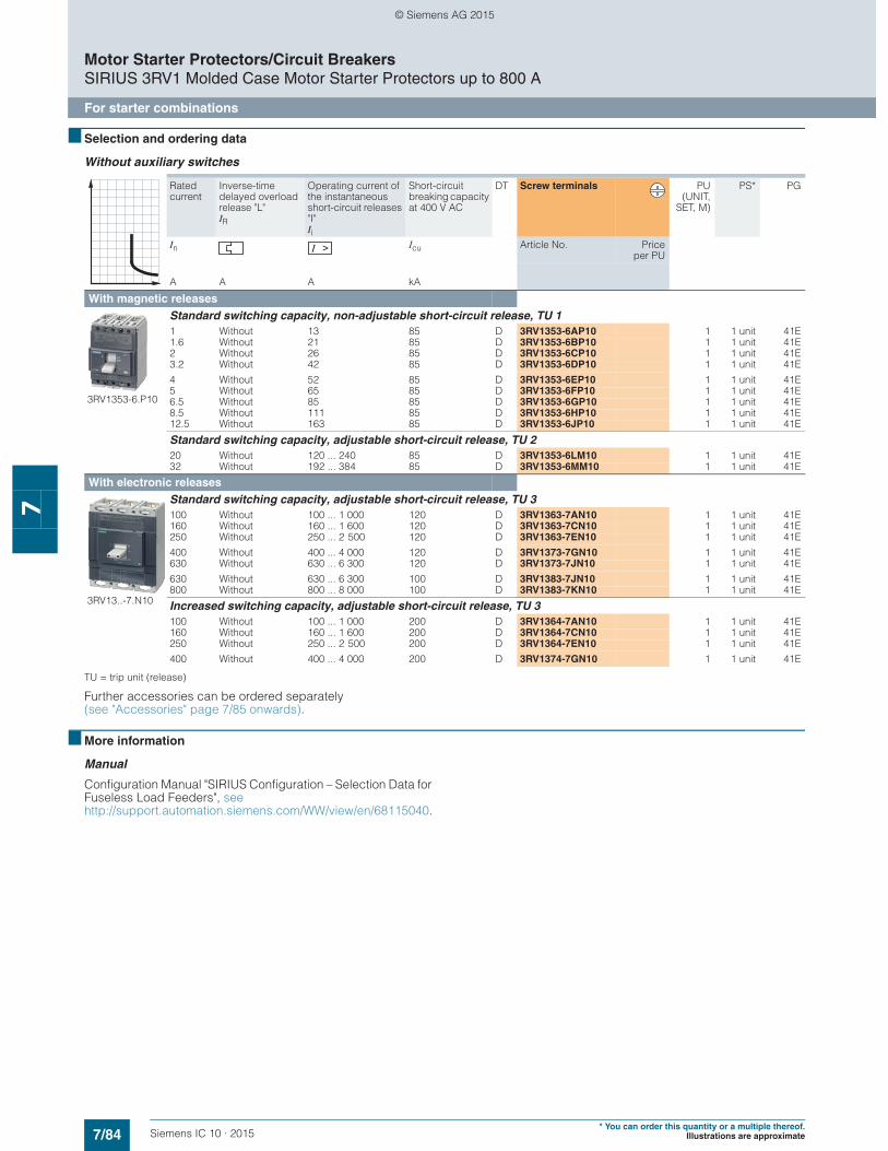
7/84 Siemens IC 10 · 2015* You can order this quantity or a multiple thereof.
Illustrations are approximate
Motor Starter Protectors/Circuit BreakersSIRIUS 3RV1 Molded Case Motor Starter Protectors up to 800 A
For starter combinations
7
■ Selection and ordering data
Without auxiliary switches
TU = trip unit (release)
Further accessories can be ordered separately (see "Accessories" page 7/85 onwards).
■ More information
Manual
Configuration Manual "SIRIUS Configuration – Selection Data for Fuseless Load Feeders", see http://support.automation.siemens.com/WW/view/en/68115040.
Rated current
Inverse-time delayed overload release "L"IR
Operating current of the instantaneous short-circuit releases "I" Ii
Short-circuit breaking capacity at 400 V AC
DT Screw terminals PU(UNIT,
SET, M)
PS* PG
In Icu Article No. Priceper PU
A A A kA
With magnetic releases
3RV1353-6.P10
Standard switching capacity, non-adjustable short-circuit release, TU 11 Without 13 85 D 3RV1353-6AP10 1 1 unit 41E1.6 Without 21 85 D 3RV1353-6BP10 1 1 unit 41E2 Without 26 85 D 3RV1353-6CP10 1 1 unit 41E3.2 Without 42 85 D 3RV1353-6DP10 1 1 unit 41E
4 Without 52 85 D 3RV1353-6EP10 1 1 unit 41E5 Without 65 85 D 3RV1353-6FP10 1 1 unit 41E6.5 Without 85 85 D 3RV1353-6GP10 1 1 unit 41E8.5 Without 111 85 D 3RV1353-6HP10 1 1 unit 41E12.5 Without 163 85 D 3RV1353-6JP10 1 1 unit 41E
Standard switching capacity, adjustable short-circuit release, TU 220 Without 120 ... 240 85 D 3RV1353-6LM10 1 1 unit 41E32 Without 192 ... 384 85 D 3RV1353-6MM10 1 1 unit 41E
With electronic releases
3RV13..-7.N10
Standard switching capacity, adjustable short-circuit release, TU 3100 Without 100 ... 1 000 120 D 3RV1363-7AN10 1 1 unit 41E160 Without 160 ... 1 600 120 D 3RV1363-7CN10 1 1 unit 41E250 Without 250 ... 2 500 120 D 3RV1363-7EN10 1 1 unit 41E
400 Without 400 ... 4 000 120 D 3RV1373-7GN10 1 1 unit 41E630 Without 630 ... 6 300 120 D 3RV1373-7JN10 1 1 unit 41E
630 Without 630 ... 6 300 100 D 3RV1383-7JN10 1 1 unit 41E800 Without 800 ... 8 000 100 D 3RV1383-7KN10 1 1 unit 41E
Increased switching capacity, adjustable short-circuit release, TU 3100 Without 100 ... 1 000 200 D 3RV1364-7AN10 1 1 unit 41E160 Without 160 ... 1 600 200 D 3RV1364-7CN10 1 1 unit 41E250 Without 250 ... 2 500 200 D 3RV1364-7EN10 1 1 unit 41E
400 Without 400 ... 4 000 200 D 3RV1374-7GN10 1 1 unit 41E
© Siemens AG 2015
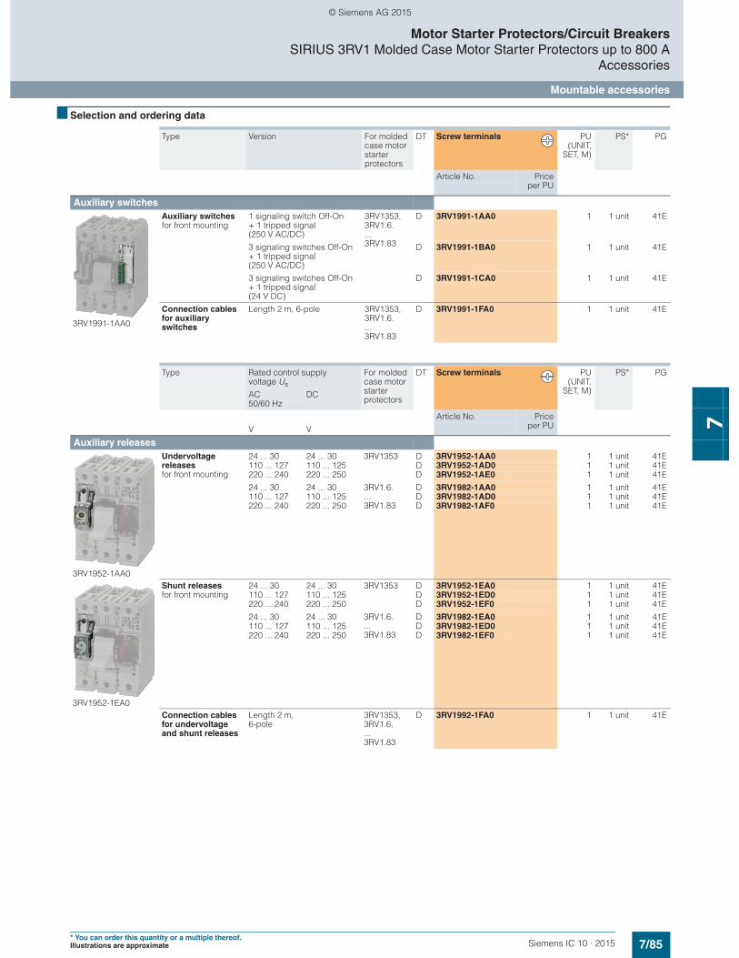
7/85Siemens IC 10 · 2015* You can order this quantity or a multiple thereof.Illustrations are approximate
Motor Starter Protectors/Circuit BreakersSIRIUS 3RV1 Molded Case Motor Starter Protectors up to 800 A
Accessories
Mountable accessories
7
■ Selection and ordering data
Type Version For molded case motor starter protectors
DT Screw terminals PU(UNIT,
SET, M)
PS* PG
Article No. Priceper PU
Auxiliary switches
3RV1991-1AA0
Auxiliary switches for front mounting
1 signaling switch Off-On + 1 tripped signal (250 V AC/DC)
3RV1353, 3RV1.6. ... 3RV1.83
D 3RV1991-1AA0 1 1 unit 41E
3 signaling switches Off-On + 1 tripped signal (250 V AC/DC)
D 3RV1991-1BA0 1 1 unit 41E
3 signaling switches Off-On + 1 tripped signal (24 V DC)
D 3RV1991-1CA0 1 1 unit 41E
Connection cables for auxiliary switches
Length 2 m, 6-pole 3RV1353, 3RV1.6. ... 3RV1.83
D 3RV1991-1FA0 1 1 unit 41E
Type Rated control supply voltage Us
For molded case motor starter protectors
DT Screw terminals PU(UNIT,
SET, M)
PS* PG
AC DC50/60 Hz
Article No. Priceper PUV V
Auxiliary releases
3RV1952-1AA0
Undervoltage releases for front mounting
24 ... 30 24 ... 30 3RV1353 D 3RV1952-1AA0 1 1 unit 41E110 ... 127 110 ... 125 D 3RV1952-1AD0 1 1 unit 41E220 ... 240 220 ... 250 D 3RV1952-1AE0 1 1 unit 41E
24 ... 30 24 ... 30 3RV1.6. ... 3RV1.83
D 3RV1982-1AA0 1 1 unit 41E110 ... 127 110 ... 125 D 3RV1982-1AD0 1 1 unit 41E220 ... 240 220 ... 250 D 3RV1982-1AF0 1 1 unit 41E
3RV1952-1EA0
Shunt releases for front mounting
24 ... 30 24 ... 30 3RV1353 D 3RV1952-1EA0 1 1 unit 41E110 ... 127 110 ... 125 D 3RV1952-1ED0 1 1 unit 41E220 ... 240 220 ... 250 D 3RV1952-1EF0 1 1 unit 41E
24 ... 30 24 ... 30 3RV1.6. ... 3RV1.83
D 3RV1982-1EA0 1 1 unit 41E110 ... 127 110 ... 125 D 3RV1982-1ED0 1 1 unit 41E220 ... 240 220 ... 250 D 3RV1982-1EF0 1 1 unit 41E
Connection cables for undervoltage and shunt releases
Length 2 m, 6-pole
3RV1353, 3RV1.6. ... 3RV1.83
D 3RV1992-1FA0 1 1 unit 41E
© Siemens AG 2015
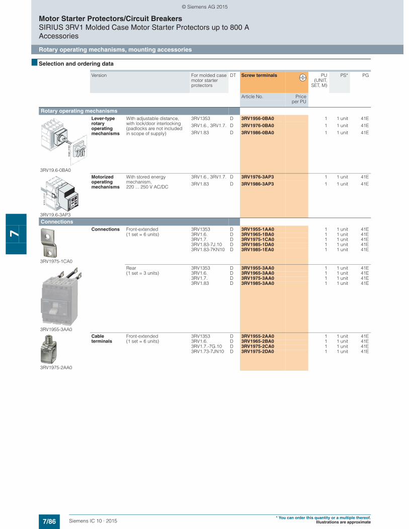
7/86 Siemens IC 10 · 2015* You can order this quantity or a multiple thereof.
Illustrations are approximate
Motor Starter Protectors/Circuit BreakersSIRIUS 3RV1 Molded Case Motor Starter Protectors up to 800 AAccessories
Rotary operating mechanisms, mounting accessories
7
■ Selection and ordering data
Version For molded case motor starter protectors
DT Screw terminals PU(UNIT,
SET, M)
PS* PG
Article No. Priceper PU
Rotary operating mechanisms
3RV19.6-0BA0
Lever-type rotary operating mechanisms
With adjustable distance, with lock/door interlocking(padlocks are not included in scope of supply)
3RV1353 D 3RV1956-0BA0 1 1 unit 41E
3RV1.6., 3RV1.7. D 3RV1976-0BA0 1 1 unit 41E
3RV1.83 D 3RV1986-0BA0 1 1 unit 41E
3RV19.6-3AP3
Motorized operating mechanisms
With stored energy mechanism,220 ... 250 V AC/DC
3RV1.6., 3RV1.7. D 3RV1976-3AP3 1 1 unit 41E
3RV1.83 D 3RV1986-3AP3 1 1 unit 41E
Connections
3RV1975-1CA0
Connections Front-extended 3RV1353 D 3RV1955-1AA0 1 1 unit 41E(1 set = 6 units) 3RV1.6. D 3RV1965-1BA0 1 1 unit 41E
3RV1.7. D 3RV1975-1CA0 1 1 unit 41E3RV1.83-7J.10 D 3RV1985-1DA0 1 1 unit 41E3RV1.83-7KN10 D 3RV1985-1EA0 1 1 unit 41E
3RV1955-3AA0
Rear 3RV1353 D 3RV1955-3AA0 1 1 unit 41E(1 set = 3 units) 3RV1.6. D 3RV1965-3AA0 1 1 unit 41E
3RV1.7. D 3RV1975-3AA0 1 1 unit 41E3RV1.83 D 3RV1985-3AA0 1 1 unit 41E
3RV1975-2AA0
Cable terminals
Front-extended 3RV1353 D 3RV1955-2AA0 1 1 unit 41E(1 set = 6 units) 3RV1.6. D 3RV1965-2BA0 1 1 unit 41E
3RV1.7.-7G.10 D 3RV1975-2CA0 1 1 unit 41E3RV1.73-7JN10 D 3RV1975-2DA0 1 1 unit 41E
NSB
0_01
962
© Siemens AG 2015
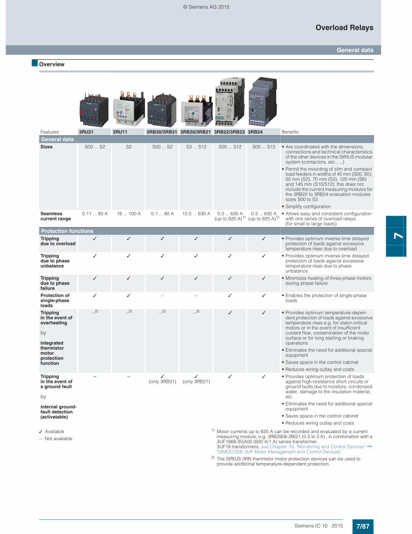
7/87Siemens IC 10 · 2015
Overload Relays
General data
7
■ Overview
✓ Available
-- Not available
1) Motor currents up to 820 A can be recorded and evaluated by a current measuring module, e.g. 3RB2906-2BG1 (0.3 to 3 A) , in combination with a 3UF1868-3GA00 (820 A/1 A) series transformer. 3UF18 transformers, see Chapter 10, "Monitoring and Control Devices" ➞ "SIMOCODE 3UF Motor Management and Control Devices".
2) The SIRIUS 3RN thermistor motor protection devices can be used to provide additional temperature-dependent protection.
Features 3RU21 3RU11 3RB30/3RB31 3RB20/3RB21 3RB22/3RB23 3RB24 Benefits
General dataSizes S00 ... S2 S3 S00 ... S2 S3 ... S12 S00 ... S12 S00 ... S12 • Are coordinated with the dimensions,
connections and technical characteristics of the other devices in the SIRIUS modular system (contactors, etc., ...)
• Permit the mounting of slim and compact load feeders in widths of 45 mm (S00, S0), 55 mm (S2), 70 mm (S3), 120 mm (S6) and 145 mm (S10/S12); this does not include the current measuring modules for the 3RB22 to 3RB24 evaluation modules sizes S00 to S3
• Simplify configuration
Seamless current range
0.11 ... 80 A 18 ... 100 A 0.1 ... 80 A 12.5 ... 630 A 0.3 ... 630 A (up to 820 A)1)
0.3 ... 630 A (up to 820 A)1)
• Allows easy and consistent configuration with one series of overload relays (for small to large loads)
Protection functionsTripping due to overload
✓ ✓ ✓ ✓ ✓ ✓ • Provides optimum inverse-time delayed protection of loads against excessive temperature rises due to overload
Tripping due to phase unbalance
✓ ✓ ✓ ✓ ✓ ✓ • Provides optimum inverse-time delayed protection of loads against excessive temperature rises due to phase unbalance
Tripping due to phase failure
✓ ✓ ✓ ✓ ✓ ✓ • Minimizes heating of three-phase motors during phase failure
Protection of single-phase loads
✓ ✓ -- -- ✓ ✓ • Enables the protection of single-phase loads
Tripping in the event of overheating
by
integrated thermistor motor protection function
--2) --2) --2) --2) ✓ ✓ • Provides optimum temperature-depen-dent protection of loads against excessive temperature rises e.g. for stator-critical motors or in the event of insufficient coolant flow, contamination of the motor surface or for long starting or braking operations
• Eliminates the need for additional special equipment
• Saves space in the control cabinet
• Reduces wiring outlay and costs
Tripping in the event ofa ground fault
by
internal ground-fault detection (activatable)
-- -- ✓(only 3RB31)
✓(only 3RB21)
✓ ✓ • Provides optimum protection of loads against high-resistance short circuits or ground faults due to moisture, condensed water, damage to the insulation material, etc.
• Eliminates the need for additional special equipment
• Saves space in the control cabinet
• Reduces wiring outlay and costs
© Siemens AG 2015

7/88 Siemens IC 10 · 2015
Overload Relays
General data
7
✓ Available
-- Not available
Features 3RU21 3RU11 3RB30/3RB31 3RB20/3RB21 3RB22/3RB23 3RB24 Benefits
FeaturesRESET function ✓ ✓ ✓ ✓ ✓ ✓ • Allows manual or automatic resetting of
the device
Remote RESET function
✓ (by means of
separate module)
✓ (by means of
separate module)
✓ (only with
3RB31 and external
auxiliary voltage
24 V DC)
✓ (only with
3RB21 and external
auxiliary voltage
24 V DC)
✓(electrically via
external button)
✓(electrically
with button or via IO-Link)
• Allows the remote resetting of the device
TEST function for auxiliary contacts
✓ ✓ ✓ ✓ ✓ ✓ • Allows easy checking of the function and wiring
TEST function for electronics
-- -- ✓ ✓ ✓ ✓ • Allows checking of the electronics
Status display ✓ ✓ ✓ ✓ ✓ ✓ • Displays the current operating state
Large current adjustment button
✓ ✓ ✓ ✓ ✓ ✓ • Makes it easier to set the relay exactly to the correct current value
Integrated auxiliary contacts (1 NO + 1 NC)
✓ ✓ ✓ ✓ ✓
(2 ×)
-- • Allows the load to be switched off if necessary
• Can be used to output signals
Integrated auxiliary contacts (1 CO and 1 NO in series)
-- -- -- -- -- ✓ • Enables the controlling of contactors directly from the higher-level control system through IO-Link
IO-Link connection
-- -- -- -- -- ✓ • Reduction of wiring in the control cabinet
• Enables communication
Connection of optional hand-held device
-- -- -- -- -- ✓ • Enables local operation
Communication capability through IO-LinkFull starter functionality through IO-Link
-- -- -- -- -- ✓ • Enables in combination with the SIRIUS 3RT contactors the assembly of communication-capable motor starters (direct-on-line, reversing and wye-delta starting)
Reading out of diagnostics functions
-- -- -- -- -- ✓ • Enables the reading out of diagnostics information such as overload, open circuit, ground fault, etc.
Reading out of current values
-- -- -- -- -- ✓ • Enables the reading out of current values and their direct processing in the higher-level control system
Reading out all set parameters
-- -- -- -- -- ✓ • Enables the reading out of all set parame-ters, e.g. for plant documentation
© Siemens AG 2015
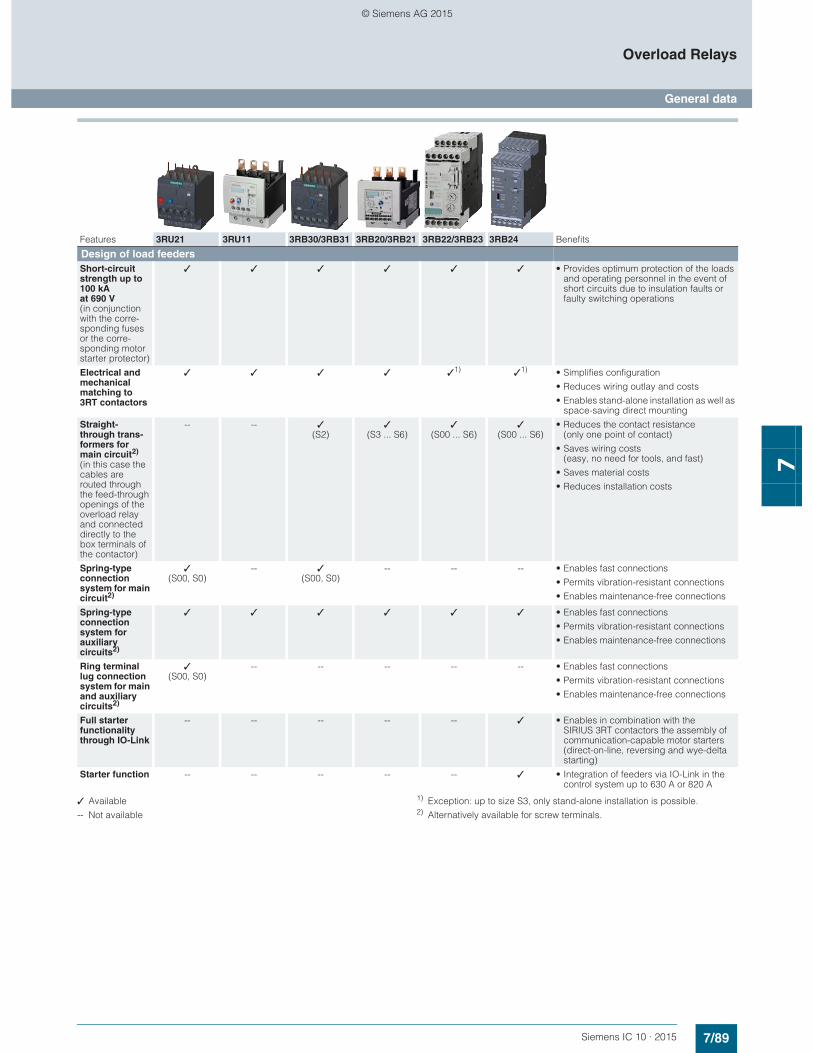
7/89Siemens IC 10 · 2015
Overload Relays
General data
7✓ Available
-- Not available
1) Exception: up to size S3, only stand-alone installation is possible.2) Alternatively available for screw terminals.
Features 3RU21 3RU11 3RB30/3RB31 3RB20/3RB21 3RB22/3RB23 3RB24 Benefits
Design of load feedersShort-circuit strength up to 100 kA at 690 V(in conjunction with the corre-sponding fuses or the corre-sponding motor starter protector)
✓ ✓ ✓ ✓ ✓ ✓ • Provides optimum protection of the loads and operating personnel in the event of short circuits due to insulation faults or faulty switching operations
Electrical and mechanical matching to 3RT contactors
✓ ✓ ✓ ✓ ✓1) ✓1) • Simplifies configuration
• Reduces wiring outlay and costs
• Enables stand-alone installation as well as space-saving direct mounting
Straight-through trans-formers for main circuit2)
(in this case the cables are routed through the feed-through openings of the overload relay and connected directly to the box terminals of the contactor)
-- -- ✓(S2)
✓(S3 ... S6)
✓(S00 ... S6)
✓(S00 ... S6)
• Reduces the contact resistance (only one point of contact)
• Saves wiring costs (easy, no need for tools, and fast)
• Saves material costs
• Reduces installation costs
Spring-type connection system for main circuit2)
✓(S00, S0)
-- ✓(S00, S0)
-- -- -- • Enables fast connections
• Permits vibration-resistant connections
• Enables maintenance-free connections
Spring-type connection system for auxiliary circuits2)
✓ ✓ ✓ ✓ ✓ ✓ • Enables fast connections
• Permits vibration-resistant connections
• Enables maintenance-free connections
Ring terminal lug connection system for main and auxiliary circuits2)
✓(S00, S0)
-- -- -- -- -- • Enables fast connections
• Permits vibration-resistant connections
• Enables maintenance-free connections
Full starter functionality through IO-Link
-- -- -- -- -- ✓ • Enables in combination with the SIRIUS 3RT contactors the assembly of communication-capable motor starters (direct-on-line, reversing and wye-delta starting)
Starter function -- -- -- -- -- ✓ • Integration of feeders via IO-Link in the control system up to 630 A or 820 A
© Siemens AG 2015
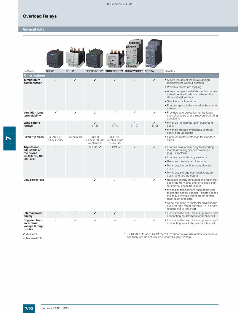
7/90 Siemens IC 10 · 2015
Overload Relays
General data
7
✓ Available
-- Not available
1) SIRIUS 3RU11 and 3RU21 thermal overload relays use a bimetal contactor and therefore do not require a control supply voltage.
Features 3RU21 3RU11 3RB30/3RB31 3RB20/3RB21 3RB22/3RB23 3RB24 Benefits
Other featuresTemperature compensation
✓ ✓ ✓ ✓ ✓ ✓ • Allows the use of the relays at high temperatures without derating
• Prevents premature tripping
• Allows compact installation of the control cabinet without distance between the devices/load feeders
• Simplifies configuration
• Enables space to be saved in the control cabinet
Very high long-term stability
✓ ✓ ✓ ✓ ✓ ✓ • Provides safe protection for the loads even after years of use in severe operating conditions
Wide setting ranges
-- -- ✓(1:4)
✓(1:4)
✓(1:10)
✓(1:10)
• Minimize the configuration outlay and costs
• Minimize storage overheads, storage costs, tied-up capital
Fixed trip class CLASS 10, CLASS 10A
CLASS 10 3RB30: CLASS 10E or
CLASS 20E
3RB20: CLASS 10 or
CLASS 20
-- -- • Optimum motor protection for standard starts
Trip classes adjustable on the device CLASS 5E, 10E, 20E, 30E
-- -- 3RB31: ✓ 3RB21: ✓ ✓ ✓ • Enables solutions for very fast starting motors requiring special protection (e.g. Ex motors)
• Enables heavy starting solutions
• Reduces the number of variants
• Minimizes the configuring outlay and costs
• Minimizes storage overhead, storage costs, and tied-up capital
Low power loss -- -- ✓ ✓ ✓ ✓ • Reduces energy consumption and energy costs (up 98 % less energy is used than for thermal overload relays)
• Minimizes temperature rises of the con-tactor and control cabinet – in some cases this may eliminate the need for control-gear cabinet cooling
• Direct mounting to contactor saves space, even for high motor currents (i.e. no heat decoupling is required)
Internal power supply
--1) --1) ✓ ✓ -- -- • Eliminates the need for configuration and connecting an additional control circuit
Supplied from an external voltage through IO-Link
-- -- -- -- -- ✓ • Eliminates the need for configuration and connecting an additional control circuit
© Siemens AG 2015
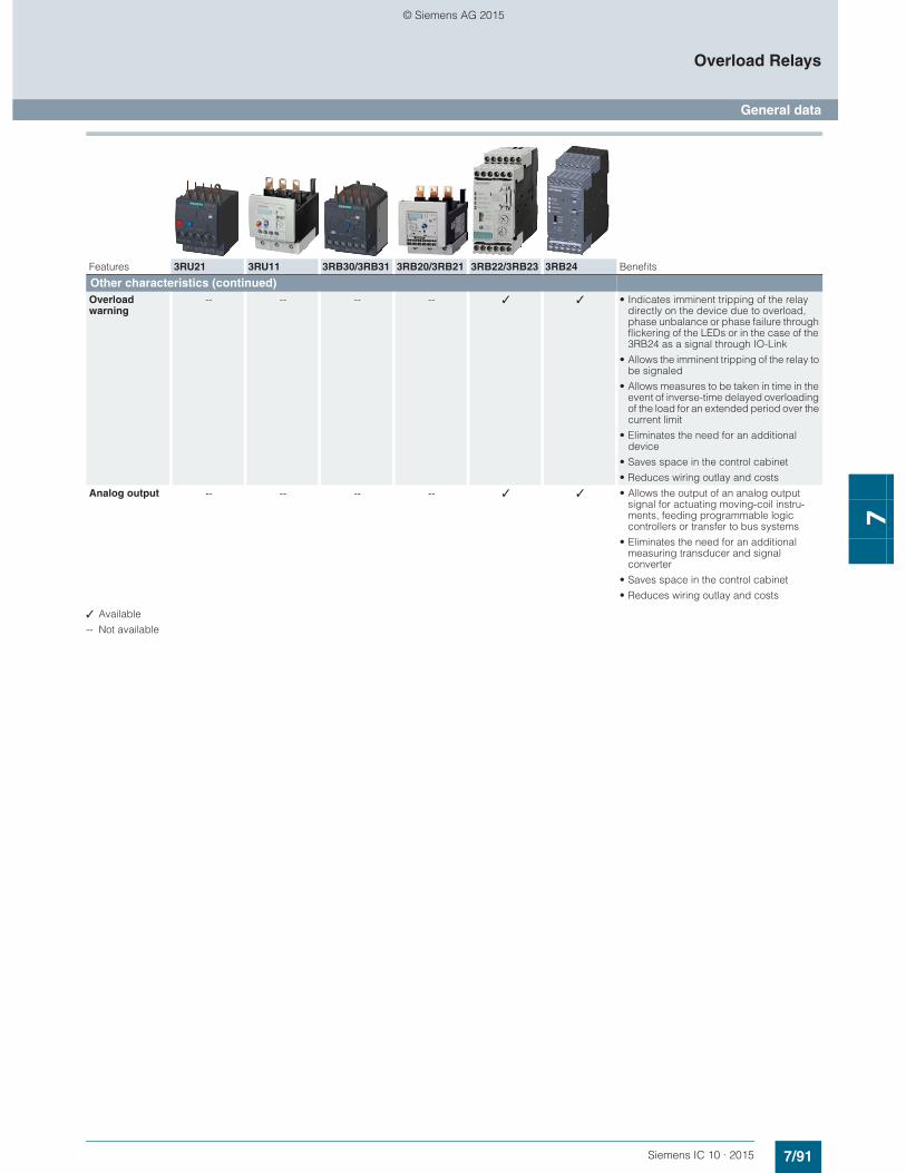
7/91Siemens IC 10 · 2015
Overload Relays
General data
7
✓ Available
-- Not available
Features 3RU21 3RU11 3RB30/3RB31 3RB20/3RB21 3RB22/3RB23 3RB24 Benefits
Other characteristics (continued)Overload warning
-- -- -- -- ✓ ✓ • Indicates imminent tripping of the relay directly on the device due to overload, phase unbalance or phase failure through flickering of the LEDs or in the case of the 3RB24 as a signal through IO-Link
• Allows the imminent tripping of the relay to be signaled
• Allows measures to be taken in time in the event of inverse-time delayed overloading of the load for an extended period over the current limit
• Eliminates the need for an additional device
• Saves space in the control cabinet
• Reduces wiring outlay and costs
Analog output -- -- -- -- ✓ ✓ • Allows the output of an analog output signal for actuating moving-coil instru-ments, feeding programmable logic controllers or transfer to bus systems
• Eliminates the need for an additional measuring transducer and signal converter
• Saves space in the control cabinet
• Reduces wiring outlay and costs
© Siemens AG 2015

7/92 Siemens IC 10 · 2015
Overload Relays
General data
7
Overview of overload relays – matching contactors
✓ Can be used
-- Cannot be used
1) "Technical specifications" for the use of overload relays with trip class ≥ CLASS 20 can be found in "Short-circuit protection with fuses for motor feeders", see Configuration Manuals- "SIRIUS Configuration – Selection data for Fuseless Load Feeders",
http://support.automation.siemens.com/WW/view/en/68115040.- "Configuring SIRIUS Innovations – Selection data for Fuseless and
Fused Load Feeders", http://support.automation.siemens.com/WW/view/en/50250599.
Overload relays
Current measure-ment
Current range
Contactors (type, size, rating in kW)
3RT201. 3RT202. 3RT203. 3RT104. 3RT105. 3RT106. 3RT107. 3TF68/3TF69
S00 S0 S2 S3 S6 S10 S12 S14
Type A 3/4/5.5/7.5 5.5/7.5/11/15/18.5 15/18.5/22/30/37
30/37/45 55/75/90 110/132/160 200/250 375/450
SIRIUS 3RU21 thermal overload relays
3RU21
3RU211 Integrated 0.11 … 16 ✓ -- -- -- -- -- -- --
3RU212 Integrated 1.8 … 40 -- ✓ -- -- -- -- -- --
3RU213 Integrated 11 … 80 -- -- ✓ -- -- -- -- --
SIRIUS 3RU11 thermal overload relays
3RU11
3RU114 Integrated 18 … 100 -- -- -- ✓ -- -- -- --
SIRIUS 3RB30 electronic overload relays1)
3RB30
3RB301 Integrated 0.1 … 16 ✓ -- -- -- -- -- -- --
3RB302 Integrated 0.1 … 40 -- ✓ -- -- -- -- -- --
3RB303 Integrated 12.5 … 80 -- -- ✓ -- -- -- -- --
SIRIUS 3RB31 electronic overload relays1)
3RB311 Integrated 0.1 … 16 ✓ -- -- -- -- -- -- --
3RB312 Integrated 0.1 … 40 -- ✓ -- -- -- -- -- --
3RB313 Integrated 12.5 … 80 -- -- ✓ -- -- -- -- --
SIRIUS 3RB20 electronic overload relays1)
3RB20
3RB204 Integrated 12.5 … 100 -- -- -- ✓ -- -- -- --
3RB205 Integrated 50 … 200 -- -- -- -- ✓ -- -- --
3RB206 Integrated 55 … 630 -- -- -- -- -- ✓ ✓ ✓
3RB201 + 3UF18
Integrated 630 … 820 -- -- -- -- -- -- -- ✓
SIRIUS 3RB21 electronic overload relays1)
3RB21
3RB214 Integrated 12.5 … 100 -- -- -- ✓ -- -- -- --
3RB215 Integrated 50 … 200 -- -- -- -- ✓ -- -- --
3RB216 Integrated 55 … 630 -- -- -- -- -- ✓ ✓ ✓
3RB211 + 3UF18
Integrated 630 … 820 -- -- -- -- -- -- -- ✓
© Siemens AG 2015
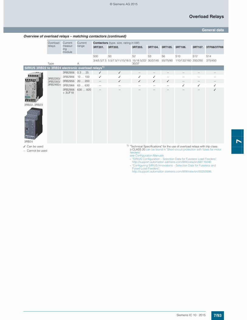
7/93Siemens IC 10 · 2015
Overload Relays
General data
7
Overview of overload relays – matching contactors (continued)
✓ Can be used
-- Cannot be used
1) "Technical Specifications" for the use of overload relays with trip class ≥ CLASS 20 can be found in "Short-circuit protection with fuses for motor feeders", see Configuration Manuals- "SIRIUS Configuration – Selection Data for Fuseless Load Feeders",
http://support.automation.siemens.com/WW/view/en/68115040- "Configuring SIRIUS Innovations – Selection Data for Fuseless and
Fused Load Feeders", http://support.automation.siemens.com/WW/view/en/50250599.
Overload relays
Current measur-ing module
Current range
Contactors (type, size, rating in kW)
3RT201. 3RT202. 3RT203. 3RT104. 3RT105. 3RT106. 3RT107. 3TF68/3TF69
S00 S0 S2 S3 S6 S10 S12 S14
Type A3/4/5.5/7.5 5.5/7.5/11/15/18.5 15/18.5/22/
30/3730/37/45 55/75/90 110/132/160 200/250 375/450
SIRIUS 3RB22 to 3RB24 electronic overload relays1)
3RB22, 3RB23
3RB24
3RB2283/3RB2383/3RB2483+
3RB2906 0.3 … 25 ✓ ✓ -- -- -- -- -- --
3RB2906 10 … 100 ✓ ✓ ✓ ✓ -- -- -- --
3RB2956 20 … 200 -- ✓ ✓ ✓ ✓ -- -- --
3RB2966 63 … 630 -- -- -- -- -- ✓ ✓ ✓
3RB2906 + 3UF18
630 … 820 -- -- -- -- -- -- -- ✓
© Siemens AG 2015

7/94 Siemens IC 10 · 2015
Overload Relays
General data
7
Connection methods
3RU2 thermal overload relays• Sizes S00 and S0:
- Main and auxiliary circuit: Either screw terminals, spring-type terminals or ring terminal lug connections
• Size S2:- Main circuit: Screw terminals with box terminal- Auxiliary circuit: Either screw or spring-type terminals
3RU1 thermal overload relays• Size S3:
- Main circuit: Screw terminals- Auxiliary circuit: Either screw or spring-type terminals
3RB3 electronic overload relays• Sizes S00 and S0:
- Main and auxiliary circuit: Either screw or spring-type terminals
• Size S2:- Main circuit: Screw terminals with box terminal or as
straight-through transformer- Auxiliary circuit: Either screw or spring-type terminals
3RB2 electronic overload relays
3RB20 and 3RB21 overload relays:• Size S3:
- Main circuit: Screw terminals with box terminal or as straight-through transformer
- Auxiliary circuit: Either screw or spring-type terminals• Size S6:
- Main circuit: With busbar connection or as straight-through transformer
- Auxiliary circuit: Either screw or spring-type terminals• Sizes S10/S12:
- Main circuit: With busbar connection- Auxiliary circuit: Either screw or spring-type terminals
3RB22 to 3RB24 evaluation modules:• Screw or spring-type terminals
3RB29 current measuring modules:• Up to size S3: Straight-through transformers• As from size S6:
- Main circuit: With busbar connection- Auxiliary circuit: Either screw or spring-type terminals
Screw terminals
Spring-type terminals
Ring terminal lug connections
Busbar connections
Straight-through transformers
The various terminals and straight-through transformers are indicated in the corresponding tables by the symbols shown on orange backgrounds.
© Siemens AG 2015
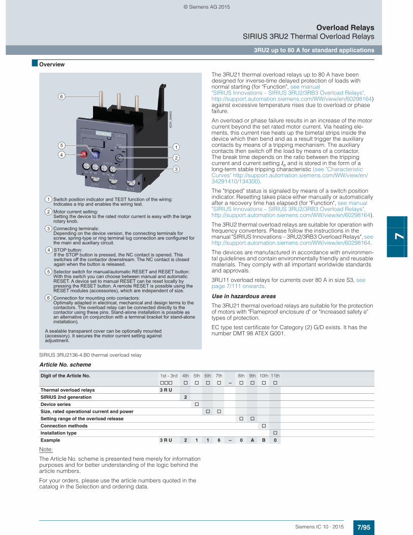
7/95Siemens IC 10 · 2015
Overload RelaysSIRIUS 3RU2 Thermal Overload Relays
3RU2 up to 80 A for standard applications
7
■ Overview
SIRIUS 3RU2136-4.B0 thermal overload relay
The 3RU21 thermal overload relays up to 80 A have been designed for inverse-time delayed protection of loads with normal starting (for "Function", see manual "SIRIUS Innovations – SIRIUS 3RU2/3RB3 Overload Relays", http://support.automation.siemens.com/WW/view/en/60298164)against excessive temperature rises due to overload or phase failure.
An overload or phase failure results in an increase of the motor current beyond the set rated motor current. Via heating ele-ments, this current rise heats up the bimetal strips inside the device which then bend and as a result trigger the auxiliary contacts by means of a tripping mechanism. The auxiliary contacts then switch off the load by means of a contactor. The break time depends on the ratio between the tripping current and current setting Ie and is stored in the form of a long-term stable tripping characteristic (see "Characteristic Curves" http://support.automation.siemens.com/WW/view/en/34291410/134300).
The "tripped" status is signaled by means of a switch position indicator. Resetting takes place either manually or automatically after a recovery time has elapsed (for "Function", see manual "SIRIUS Innovations – SIRIUS 3RU2/3RB3 Overload Relays", http://support.automation.siemens.com/WW/view/en/60298164).
The 3RU2 thermal overload relays are suitable for operation with frequency converters. Please follow the instructions in the manual "SIRIUS Innovations – 3RU2/3RB3 Overload Relays", see http://support.automation.siemens.com/WW/view/en/60298164.
The devices are manufactured in accordance with environmen-tal guidelines and contain environmentally friendly and reusable materials. They comply with all important worldwide standards and approvals.
3RU11 overload relays for currents over 80 A in size S3, see page 7/111 onwards.
Use in hazardous areas
The 3RU21 thermal overload relays are suitable for the protection of motors with "Flameproof enclosure d" or "Increased safety e" types of protection.
EC type test certificate for Category (2) G/D exists. It has the number DMT 98 ATEX G001.
Article No. scheme
Note:
The Article No. scheme is presented here merely for information purposes and for better understanding of the logic behind the article numbers.
For your orders, please use the article numbers quoted in the catalog in the Selection and ordering data.
6
2
15
4
3IC
01_0
0403
A sealable transparent cover can be optionally mounted (accessory). It secures the motor current setting against adjustment.
Connection for mounting onto contactors: Optimally adapted in electrical, mechanical and design terms to the contactors. The overload relay can be connected directly to the contactor using these pins. Stand-alone installation is possible as an alternative (in conjunction with a terminal bracket for stand-alone installation).
6
Selector switch for manual/automatic RESET and RESET button: With this switch you can choose between manual and automatic RESET. A device set to manual RESET can be reset locally by pressing the RESET button. A remote RESET is possible using the RESET modules (accessories), which are independent of size.
5
Switch position indicator and TEST function of the wiring: Indicates a trip and enables the wiring test.
1
Motor current setting: Setting the device to the rated motor current is easy with the large rotary knob.
2
STOP button: If the STOP button is pressed, the NC contact is opened. This switches off the contactor downstream. The NC contact is closed again when the button is released.
4
Connecting terminals: Depending on the device version, the connecting terminals for screw, spring-type or ring terminal lug connection are configured for the main and auxiliary circuit.
3
Digit of the Article No. 1st - 3rd 4th 5th 6th 7th 8th 9th 10th 11th
@@@ @ @ @ @ – @ @ @ @
Thermal overload relays 3 R U
SIRIUS 2nd generation 2
Device series @
Size, rated operational current and power @ @
Setting range of the overload release @ @
Connection methods @
Installation type @
Example 3 R U 2 1 1 6 – 0 A B 0
© Siemens AG 2015
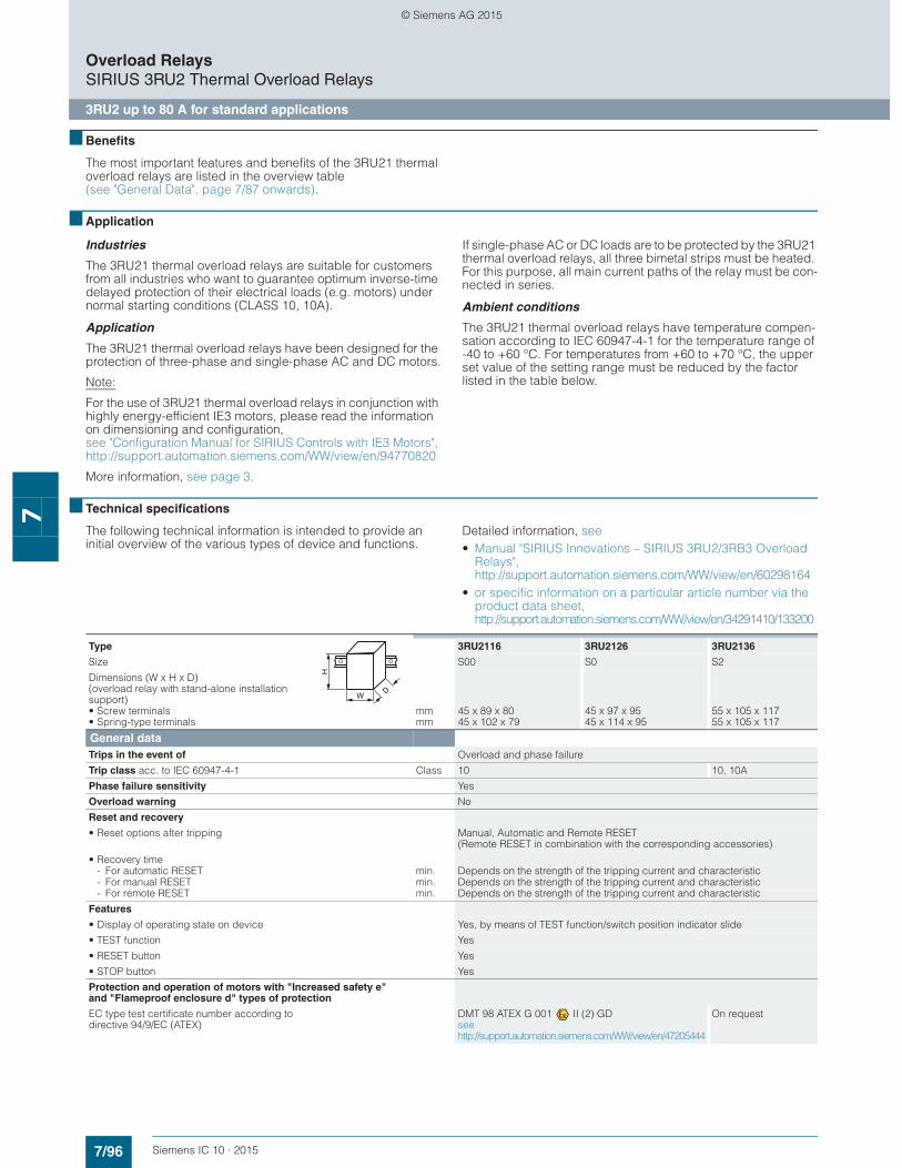
7/96 Siemens IC 10 · 2015
Overload RelaysSIRIUS 3RU2 Thermal Overload Relays
3RU2 up to 80 A for standard applications
7
■ Benefits
The most important features and benefits of the 3RU21 thermal overload relays are listed in the overview table (see "General Data", page 7/87 onwards).
■ Application
Industries
The 3RU21 thermal overload relays are suitable for customers from all industries who want to guarantee optimum inverse-time delayed protection of their electrical loads (e.g. motors) under normal starting conditions (CLASS 10, 10A).
Application
The 3RU21 thermal overload relays have been designed for the protection of three-phase and single-phase AC and DC motors.
Note:
For the use of 3RU21 thermal overload relays in conjunction with highly energy-efficient IE3 motors, please read the information on dimensioning and configuration, see "Configuration Manual for SIRIUS Controls with IE3 Motors", http://support.automation.siemens.com/WW/view/en/94770820
More information, see page 3.
If single-phase AC or DC loads are to be protected by the 3RU21 thermal overload relays, all three bimetal strips must be heated. For this purpose, all main current paths of the relay must be con-nected in series.
Ambient conditions
The 3RU21 thermal overload relays have temperature compen-sation according to IEC 60947-4-1 for the temperature range of -40 to +60 °C. For temperatures from +60 to +70 °C, the upper set value of the setting range must be reduced by the factor listed in the table below.
■ Technical specifications
The following technical information is intended to provide an initial overview of the various types of device and functions.
Detailed information, see • Manual "SIRIUS Innovations – SIRIUS 3RU2/3RB3 Overload
Relays", http://support.automation.siemens.com/WW/view/en/60298164
• or specific information on a particular article number via the product data sheet, http://support.automation.siemens.com/WW/view/en/34291410/133200
Type 3RU2116 3RU2126 3RU2136
Size S00 S0 S2
Dimensions (W x H x D)(overload relay with stand-alone installation support)• Screw terminals• Spring-type terminals
mmmm
45 x 89 x 8045 x 102 x 79
45 x 97 x 9545 x 114 x 95
55 x 105 x 11755 x 105 x 117
General dataTrips in the event of Overload and phase failure
Trip class acc. to IEC 60947-4-1 Class 10 10, 10A
Phase failure sensitivity Yes
Overload warning No
Reset and recovery
• Reset options after tripping Manual, Automatic and Remote RESET (Remote RESET in combination with the corresponding accessories)
• Recovery time- For automatic RESET min. Depends on the strength of the tripping current and characteristic- For manual RESET min. Depends on the strength of the tripping current and characteristic- For remote RESET min. Depends on the strength of the tripping current and characteristic
Features
• Display of operating state on device Yes, by means of TEST function/switch position indicator slide
• TEST function Yes
• RESET button Yes
• STOP button Yes
Protection and operation of motors with "Increased safety e" and "Flameproof enclosure d" types of protection
EC type test certificate number according to directive 94/9/EC (ATEX)
DMT 98 ATEX G 001 II (2) GDsee http://support.automation.siemens.com/WW/view/en/47205444
On request
W
H
D
© Siemens AG 2015
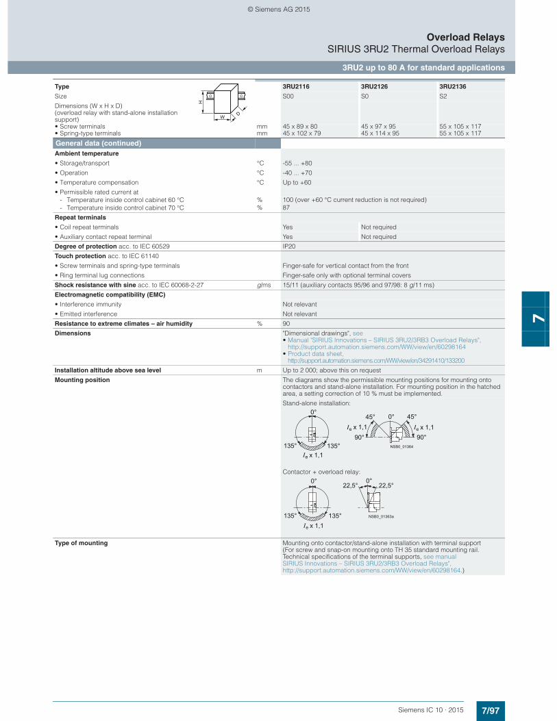
7/97Siemens IC 10 · 2015
Overload RelaysSIRIUS 3RU2 Thermal Overload Relays
3RU2 up to 80 A for standard applications
7
General data (continued)Ambient temperature
• Storage/transport °C -55 ... +80
• Operation °C -40 ... +70
• Temperature compensation °C Up to +60
• Permissible rated current at- Temperature inside control cabinet 60 °C % 100 (over +60 °C current reduction is not required)- Temperature inside control cabinet 70 °C % 87
Repeat terminals
• Coil repeat terminals Yes Not required
• Auxiliary contact repeat terminal Yes Not required
Degree of protection acc. to IEC 60529 IP20
Touch protection acc. to IEC 61140
• Screw terminals and spring-type terminals Finger-safe for vertical contact from the front
• Ring terminal lug connections Finger-safe only with optional terminal covers
Shock resistance with sine acc. to IEC 60068-2-27 g/ms 15/11 (auxiliary contacts 95/96 and 97/98: 8 g/11 ms)
Electromagnetic compatibility (EMC)
• Interference immunity Not relevant
• Emitted interference Not relevant
Resistance to extreme climates – air humidity % 90
Dimensions "Dimensional drawings", see • Manual "SIRIUS Innovations – SIRIUS 3RU2/3RB3 Overload Relays",
http://support.automation.siemens.com/WW/view/en/60298164• Product data sheet,
http://support.automation.siemens.com/WW/view/en/34291410/133200
Installation altitude above sea level m Up to 2 000; above this on request
Mounting position The diagrams show the permissible mounting positions for mounting onto contactors and stand-alone installation. For mounting position in the hatched area, a setting correction of 10 % must be implemented.
Stand-alone installation:
Contactor + overload relay:
Type of mounting Mounting onto contactor/stand-alone installation with terminal support (For screw and snap-on mounting onto TH 35 standard mounting rail. Technical specifications of the terminal supports, see manual SIRIUS Innovations – SIRIUS 3RU2/3RB3 Overload Relays", http://support.automation.siemens.com/WW/view/en/60298164.)
Type 3RU2116 3RU2126 3RU2136
Size S00 S0 S2
Dimensions (W x H x D)(overload relay with stand-alone installation support)• Screw terminals• Spring-type terminals
mmmm
45 x 89 x 8045 x 102 x 79
45 x 97 x 9545 x 114 x 95
55 x 105 x 11755 x 105 x 117
W
H
D
x 1,1ex 1,1e
0°
90°90°
x 1,1e
45°
135°
45°0°
135° NSB0_01364
x 1,1
0°
e
135°
22,5°22,5°0°
135° NSB0_01363a
© Siemens AG 2015
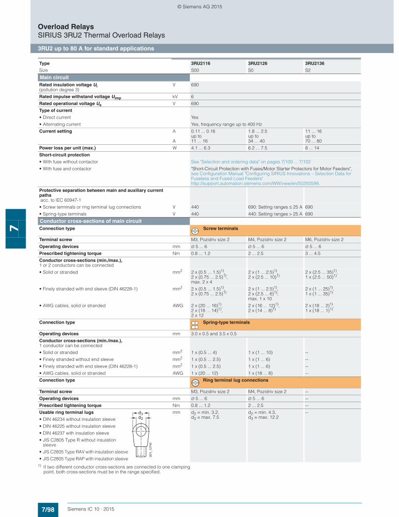
7/98 Siemens IC 10 · 2015
Overload RelaysSIRIUS 3RU2 Thermal Overload Relays
3RU2 up to 80 A for standard applications
7
1) If two different conductor cross-sections are connected to one clamping point, both cross-sections must be in the range specified.
Type 3RU2116 3RU2126 3RU2136
Size S00 S0 S2
Main circuitRated insulation voltage Ui (pollution degree 3)
V 690
Rated impulse withstand voltage Uimp kV 6
Rated operational voltage Ue V 690
Type of current
• Direct current Yes
• Alternating current Yes, frequency range up to 400 Hz
Current setting A
A
0.11 ... 0.16 up to 11 ... 16
1.8 ... 2.5 up to 34 ... 40
11 ... 16 up to 70 ... 80
Power loss per unit (max.) W 4.1 ... 6.3 6.2 ... 7.5 8 ... 14
Short-circuit protection
• With fuse without contactor See "Selection and ordering data" on pages 7/100 ... 7/102
• With fuse and contactor "Short-Circuit Protection with Fuses/Motor Starter Protectors for Motor Feeders", see Configuration Manual "Configuring SIRIUS Innovations – Selection Data for Fuseless and Fused Load Feeders" http://support.automation.siemens.com/WW/view/en/50250599.
Protective separation between main and auxiliary current paths acc. to IEC 60947-1
• Screw terminals or ring terminal lug connections V 440 690: Setting ranges ≤ 25 A 690
• Spring-type terminals V 440 440: Setting ranges > 25 A 690
Conductor cross-sections of main circuitConnection type Screw terminals
Terminal screw M3, Pozidriv size 2 M4, Pozidriv size 2 M6, Pozidriv size 2
Operating devices mm ∅ 5 ... 6 ∅ 5 ... 6 ∅ 5 ... 6
Prescribed tightening torque Nm 0.8 ... 1.2 2 ... 2.5 3 ... 4.5
Conductor cross-sections (min./max.), 1 or 2 conductors can be connected
• Solid or stranded mm2 2 x (0.5 ... 1.5)1), 2 x (0.75 ... 2.5)1), max. 2 x 4
2 x (1 ... 2.5)1), 2 x (2.5 ... 10)1)
2 x (2.5 ... 35)1), 1 x (2.5 ... 50)1)
• Finely stranded with end sleeve (DIN 46228-1) mm2 2 x (0.5 ... 1.5)1), 2 x (0.75 ... 2.5)1)
2 x (1 ... 2.5)1), 2 x (2.5 ... 6)1); max. 1 x 10
2 x (1 ... 25)1), 1 x (1 ... 35)1)
• AWG cables, solid or stranded AWG 2 x (20 ... 16)1), 2 x (18 ... 14)1),2 x 12
2 x (16 ... 12)1), 2 x (14 ... 8)1)
2 x (18 ... 2)1), 1 x (18 ... 1)1)
Connection type Spring-type terminals
Operating devices mm 3.0 x 0.5 and 3.5 x 0.5
Conductor cross-sections (min./max.), 1 conductor can be connected
• Solid or stranded mm2 1 x (0.5 ... 4) 1 x (1 ... 10) --
• Finely stranded without end sleeve mm2 1 x (0.5 ... 2.5) 1 x (1 ... 6) --
• Finely stranded with end sleeve (DIN 46228-1) mm2 1 x (0.5 ... 2.5) 1 x (1 ... 6) --
• AWG cables, solid or stranded AWG 1 x (20 ... 12) 1 x (18 ... 8) --
Connection type Ring terminal lug connections
Terminal screw M3, Pozidriv size 2 M4, Pozidriv size 2 --
Operating devices mm ∅ 5 ... 6 ∅ 5 ... 6 --
Prescribed tightening torque Nm 0.8 ... 1.2 2 ... 2.5 --
Usable ring terminal lugs mm d2 = min. 3.2, d3 = max. 7.5
d2 = min. 4.3, d3 = max. 12.2
--
• DIN 46234 without insulation sleeve
• DIN 46225 without insulation sleeve
• DIN 46237 with insulation sleeve
• JIS C2805 Type R without insulation sleeve
• JIS C2805 Type RAV with insulation sleeve
• JIS C2805 Type RAP with insulation sleeve
d2
d3
I201
_127
40
© Siemens AG 2015

7/99Siemens IC 10 · 2015
Overload RelaysSIRIUS 3RU2 Thermal Overload Relays
3RU2 up to 80 A for standard applications
7
1) If two different conductor cross-sections are connected to one clamping point, both cross-sections must be in the range specified.
Type 3RU2116 3RU2126 3RU2136
Size S00 S0 S2
Auxiliary circuitNumber of NO contacts 1
Number of NC contacts 1
Auxiliary contacts – assignment 1 NO for the signal "tripped"; 1 NC for disconnecting the contactor
Rated insulation voltage Ui (pollution degree 3)
V 690
Rated impulse withstand voltage Uimp kV 6
Contact rating of the auxiliary contacts
• NC, NO contact with alternating current AC-15, rated operational current Ie at Ue:- 24 V A 3- 120 V A 3- 125 V A 3- 230 V A 2- 400 V A 1- 600 V A 0.75- 690 V A 0.75
• NC contact, NO contact with direct current DC-13, rated operational current Ie at Ue:- 24 V A 1- 110 V A 0.22- 125 V A 0.22- 220 V A 0.11
• Contact reliability (suitability for PLC control; 17 V, 5 mA) Yes
Short-circuit protection
• With fuse- Operational class gG A 6- Quick A 10
• With miniature circuit breaker (C characteristic) A 6 (up to Ik ≤ 0.5 kA; U ≤ 260 V)
Reliable operational voltage for protective separation between auxiliary current pathsacc. to IEC 60947-1
V 440
CSA, UL, UR rated dataAuxiliary circuit – switching capacity B600, R300
Conductor cross-sections for auxiliary circuitConnection type Screw terminals
Terminal screw M3, Pozidriv size 2
Operating devices mm ∅ 5 ... 6
Prescribed tightening torque Nm 0.8 ... 1.2
Conductor cross-sections (min./max.), 1 or 2 conductors can be connected
• Solid or stranded mm2 2 x (0.5 ... 1.5)1), 2 x (0.75 ... 2.5)1)
• Finely stranded with end sleeve (DIN 46228-1) mm2 2 x (0.5 ... 1.5)1), 2 x (0.75 ... 2.5)1)
• AWG cables, solid or stranded AWG 2 x (20 ... 16)1), 2 x (18 ... 14)1)
Connection type Spring-type terminals
Operating devices mm 3.0 x 0.5 and 3.5 x 0.5
Conductor cross-sections (min./max.), 1 or 2 conductors can be connected
• Solid or stranded mm2 2 x (0.5 ... 2.5)
• Finely stranded without end sleeve mm2 2 x (0.5 ... 2.5)
• Finely stranded with end sleeve (DIN 46228-1) mm2 2 x (0.5 ... 1.5)
• AWG cables, solid or stranded AWG 2 x (20 ... 14)
Connection type Ring terminal lug connections
Terminal screw M3, Pozidriv size 2 --
Operating devices mm ∅ 5 ... 6 --
Prescribed tightening torque Nm 0.8 ... 1.2 --
Usable ring terminal lugs mm d2 = min. 3.2, d3 = max. 7.5
--
• DIN 46234 without insulation sleeve
• DIN 46225 without insulation sleeve
• DIN 46237 with insulation sleeve
• JIS C2805 Type R without insulation sleeve
• JIS C2805 Type RAV with insulation sleeve
• JIS C2805 Type RAP with insulation sleeve
d2
d3
I201
_127
40
© Siemens AG 2015
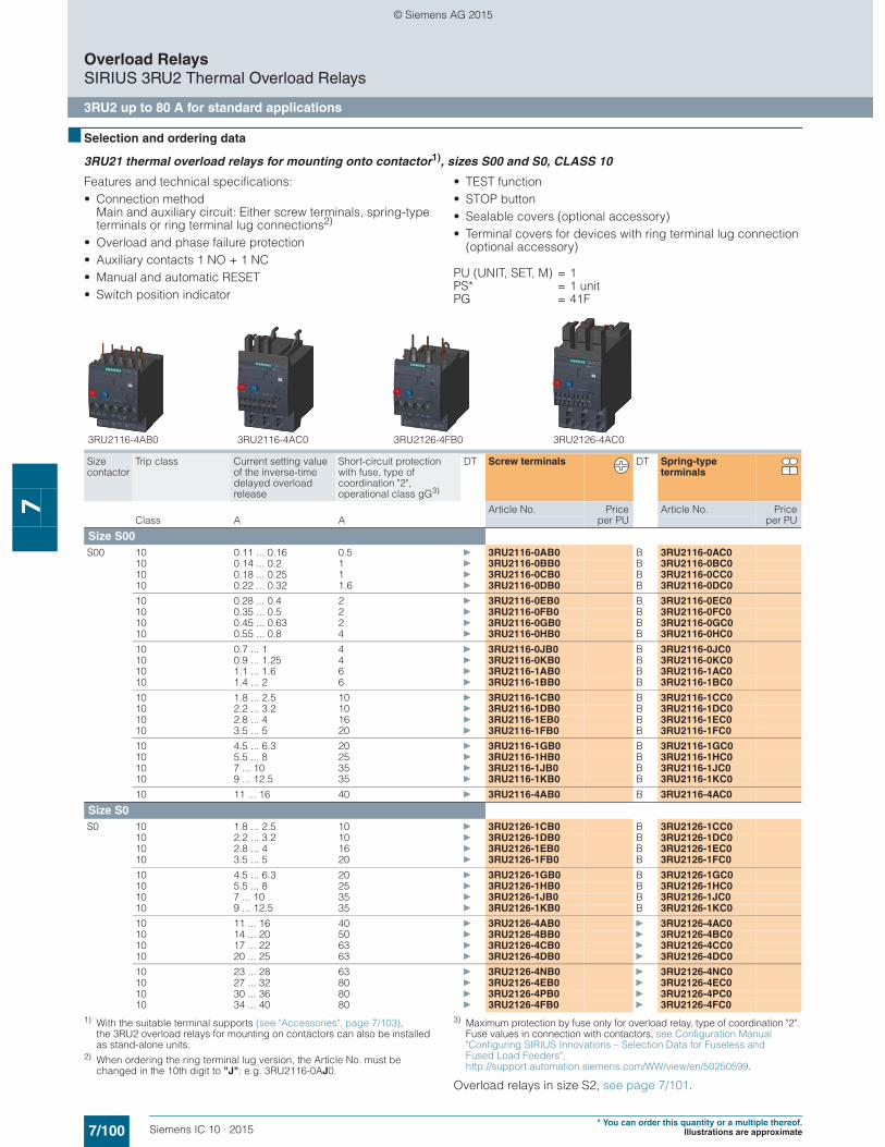
7/100 Siemens IC 10 · 2015* You can order this quantity or a multiple thereof.
Illustrations are approximate
Overload RelaysSIRIUS 3RU2 Thermal Overload Relays
3RU2 up to 80 A for standard applications
7
■ Selection and ordering data
3RU21 thermal overload relays for mounting onto contactor1), sizes S00 and S0, CLASS 10
Features and technical specifications:• Connection method
Main and auxiliary circuit: Either screw terminals, spring-type terminals or ring terminal lug connections2)
• Overload and phase failure protection• Auxiliary contacts 1 NO + 1 NC• Manual and automatic RESET• Switch position indicator
• TEST function• STOP button• Sealable covers (optional accessory)• Terminal covers for devices with ring terminal lug connection
(optional accessory)
PU (UNIT, SET, M) = 1PS* = 1 unitPG = 41F
1) With the suitable terminal supports (see "Accessories", page 7/103), the 3RU2 overload relays for mounting on contactors can also be installed as stand-alone units.
2) When ordering the ring terminal lug version, the Article No. must be changed in the 10th digit to "J": e.g. 3RU2116-0AJ0.
3) Maximum protection by fuse only for overload relay, type of coordination "2". Fuse values in connection with contactors, see Configuration Manual "Configuring SIRIUS Innovations – Selection Data for Fuseless and Fused Load Feeders", http://support.automation.siemens.com/WW/view/en/50250599.
Overload relays in size S2, see page 7/101.
Size contactor
Trip class Current setting value of the inverse-time delayed overload release
Short-circuit protection with fuse, type of coordination "2", operational class gG3)
DT Screw terminals DT Spring-type terminals
Article No. Priceper PU
Article No. Priceper PUClass A A
Size S00S00 10 0.11 ... 0.16 0.5 } 3RU2116-0AB0 B 3RU2116-0AC0
10 0.14 ... 0.2 1 } 3RU2116-0BB0 B 3RU2116-0BC010 0.18 ... 0.25 1 } 3RU2116-0CB0 B 3RU2116-0CC010 0.22 ... 0.32 1.6 } 3RU2116-0DB0 B 3RU2116-0DC0
10 0.28 ... 0.4 2 } 3RU2116-0EB0 B 3RU2116-0EC010 0.35 ... 0.5 2 } 3RU2116-0FB0 B 3RU2116-0FC010 0.45 ... 0.63 2 } 3RU2116-0GB0 B 3RU2116-0GC010 0.55 ... 0.8 4 } 3RU2116-0HB0 B 3RU2116-0HC0
10 0.7 ... 1 4 } 3RU2116-0JB0 B 3RU2116-0JC010 0.9 ... 1.25 4 } 3RU2116-0KB0 B 3RU2116-0KC010 1.1 ... 1.6 6 } 3RU2116-1AB0 B 3RU2116-1AC010 1.4 ... 2 6 } 3RU2116-1BB0 B 3RU2116-1BC0
10 1.8 ... 2.5 10 } 3RU2116-1CB0 B 3RU2116-1CC010 2.2 ... 3.2 10 } 3RU2116-1DB0 B 3RU2116-1DC010 2.8 ... 4 16 } 3RU2116-1EB0 B 3RU2116-1EC010 3.5 ... 5 20 } 3RU2116-1FB0 B 3RU2116-1FC0
10 4.5 ... 6.3 20 } 3RU2116-1GB0 B 3RU2116-1GC010 5.5 ... 8 25 } 3RU2116-1HB0 B 3RU2116-1HC010 7 ... 10 35 } 3RU2116-1JB0 B 3RU2116-1JC010 9 ... 12.5 35 } 3RU2116-1KB0 B 3RU2116-1KC0
10 11 ... 16 40 } 3RU2116-4AB0 B 3RU2116-4AC0
Size S0S0 10 1.8 ... 2.5 10 } 3RU2126-1CB0 B 3RU2126-1CC0
10 2.2 ... 3.2 10 } 3RU2126-1DB0 B 3RU2126-1DC010 2.8 ... 4 16 } 3RU2126-1EB0 B 3RU2126-1EC010 3.5 ... 5 20 } 3RU2126-1FB0 B 3RU2126-1FC0
10 4.5 ... 6.3 20 } 3RU2126-1GB0 B 3RU2126-1GC010 5.5 ... 8 25 } 3RU2126-1HB0 B 3RU2126-1HC010 7 ... 10 35 } 3RU2126-1JB0 B 3RU2126-1JC010 9 ... 12.5 35 } 3RU2126-1KB0 B 3RU2126-1KC0
10 11 ... 16 40 } 3RU2126-4AB0 } 3RU2126-4AC010 14 ... 20 50 } 3RU2126-4BB0 } 3RU2126-4BC010 17 ... 22 63 } 3RU2126-4CB0 } 3RU2126-4CC010 20 ... 25 63 } 3RU2126-4DB0 } 3RU2126-4DC0
10 23 ... 28 63 } 3RU2126-4NB0 } 3RU2126-4NC010 27 ... 32 80 } 3RU2126-4EB0 } 3RU2126-4EC010 30 ... 36 80 } 3RU2126-4PB0 } 3RU2126-4PC010 34 ... 40 80 } 3RU2126-4FB0 } 3RU2126-4FC0
3RU2116-4AB0 3RU2116-4AC0 3RU2126-4FB0 3RU2126-4AC0
© Siemens AG 2015

7/101Siemens IC 10 · 2015* You can order this quantity or a multiple thereof.Illustrations are approximate
Overload RelaysSIRIUS 3RU2 Thermal Overload Relays
3RU2 up to 80 A for standard applications
7
3RU21 thermal overload relays for mounting onto contactor1), size S2, CLASS 10
Features and technical specifications:• Connection methods
- Main circuit: Screw terminals with box terminal- Auxiliary circuit: Either screw or spring-type terminals
• Overload and phase failure protection• Auxiliary contacts 1 NO + 1 NC• Manual and automatic RESET
• Switch position indicator• TEST function• STOP button• Sealable covers (optional accessory)
PU (UNIT, SET, M) = 1PS* = 1 unitPG = 41F
1) With the suitable terminal supports (see "Accessories", page 7/103), the 3RU2 overload relays for mounting on contactors can also be installed as stand-alone units.
2) Maximum protection by fuse only for overload relay, type of coordination "2". Fuse values in connection with contactors, see Configuration Manual "Configuring SIRIUS Innovations – Selection Data for Fuseless and Fused Load Feeders", http://support.automation.siemens.com/WW/view/en/50250599.
Size contactor
Trip class Current setting value of the inverse-time delayed overload release
Short-circuit protection with fuse, type of coordination "2", operational class gG2)
DT Screw terminals DT Spring-type terminals(on auxiliary current side)
Article No. Priceper PU
Article No. Priceper PUClass A A
Size S2S2 10 11 ... 16 40 } 3RU2136-4AB0 X 3RU2136-4AD0
10 14 ... 20 50 } 3RU2136-4BB0 X 3RU2136-4BD010 18 ... 25 63 } 3RU2136-4DB0 X 3RU2136-4DD010 22 ... 32 80 } 3RU2136-4EB0 X 3RU2136-4ED0
10 28 ... 40 80 } 3RU2136-4FB0 X 3RU2136-4FD010 36 ... 45 100 } 3RU2136-4GB0 X 3RU2136-4GD010 40 ... 50 100 } 3RU2136-4HB0 X 3RU2136-4HD010 47 ... 57 100 } 3RU2136-4QB0 X 3RU2136-4QD010 54 ... 65 125 } 3RU2136-4JB0 X 3RU2136-4JD0
10A 62 ... 73 160 } 3RU2136-4KB0 X 3RU2136-4KD010A 70 ... 80 160 } 3RU2136-4RB0 X 3RU2136-4RD0
3RU2136-4.D03RU2136-4.B0
© Siemens AG 2015
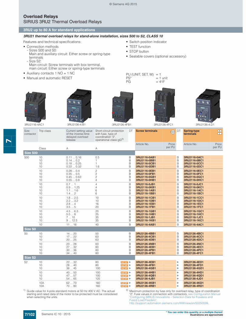
7/102 Siemens IC 10 · 2015* You can order this quantity or a multiple thereof.
Illustrations are approximate
Overload RelaysSIRIUS 3RU2 Thermal Overload Relays
3RU2 up to 80 A for standard applications
7
3RU21 thermal overload relays for stand-alone installation, sizes S00 to S2, CLASS 10
Features and technical specifications:• Connection methods
- Sizes S00 and S0: Main and auxiliary circuit: Either screw or spring-type terminals
- Size S2: Main circuit: Screw terminals with box terminal, main circuit: Either screw or spring-type terminals
• Auxiliary contacts 1 NO + 1 NC• Manual and automatic RESET
• Switch position indicator• TEST function• STOP button• Sealable covers (optional accessory)
PU (UNIT, SET, M) = 1PS* = 1 unitPG = 41F
1) Guide value for 4-pole standard motors at 50 Hz 400 V AC. The actual starting and rated data of the motor to be protected must be considered when selecting the units.
2) Maximum protection by fuse only for overload relay, type of coordination "2". Fuse values in connection with contactors, see Configuration Manual "Configuring SIRIUS Innovations – Selection Data for Fuseless and Fused Load Feeders", http://support.automation.siemens.com/WW/view/en/50250599.
Size contactor
Trip class Current setting value of the inverse-time delayed overload release
Short-circuit protection with fuse, type of coordination "2", operational class gG2)
DT Screw terminals DT Spring-type terminals
Article No. Priceper PU
Article No. Priceper PUClass A A
Size S00S00 10 0.11 ... 0.16 0.5 B 3RU2116-0AB1 B 3RU2116-0AC1
10 0.14 ... 0.2 1 B 3RU2116-0BB1 B 3RU2116-0BC110 0.18 ... 0.25 1 B 3RU2116-0CB1 B 3RU2116-0CC110 0.22 ... 0.32 1.6 B 3RU2116-0DB1 B 3RU2116-0DC1
10 0.28 ... 0.4 2 B 3RU2116-0EB1 B 3RU2116-0EC110 0.35 ... 0.5 2 B 3RU2116-0FB1 B 3RU2116-0FC110 0.45 ... 0.63 2 B 3RU2116-0GB1 B 3RU2116-0GC110 0.55 ... 0.8 4 B 3RU2116-0HB1 B 3RU2116-0HC1
10 0.7 ... 1 4 B 3RU2116-0JB1 B 3RU2116-0JC110 0.9 ... 1.25 4 B 3RU2116-0KB1 B 3RU2116-0KC110 1.1 ... 1.6 6 B 3RU2116-1AB1 B 3RU2116-1AC110 1.4 ... 2 6 B 3RU2116-1BB1 B 3RU2116-1BC1
10 1.8 ... 2.5 10 B 3RU2116-1CB1 B 3RU2116-1CC110 2.2 ... 3.2 10 B 3RU2116-1DB1 B 3RU2116-1DC110 2.8 ... 4 16 B 3RU2116-1EB1 B 3RU2116-1EC110 3.5 ... 5 20 B 3RU2116-1FB1 B 3RU2116-1FC1
10 4.5 ... 6.3 20 B 3RU2116-1GB1 B 3RU2116-1GC110 5.5 ... 8 25 B 3RU2116-1HB1 B 3RU2116-1HC110 7 ... 10 35 B 3RU2116-1JB1 B 3RU2116-1JC110 9 ... 12.5 35 B 3RU2116-1KB1 B 3RU2116-1KC1
10 11 ... 16 40 B 3RU2116-4AB1 B 3RU2116-4AC1
Size S0S0 10 14 ... 20 50 B 3RU2126-4BB1 B 3RU2126-4BC1
10 17 ... 22 63 B 3RU2126-4CB1 B 3RU2126-4CC110 20 ... 25 63 B 3RU2126-4DB1 B 3RU2126-4DC1
10 23 ... 28 63 B 3RU2126-4NB1 B 3RU2126-4NC110 27 ... 32 80 B 3RU2126-4EB1 B 3RU2126-4EC110 30 ... 36 80 B 3RU2126-4PB1 B 3RU2126-4PC110 34 ... 40 80 B 3RU2126-4FB1 B 3RU2126-4FC1
Size S2S2 10 22 ... 32 80 } 3RU2136-4EB1 } 3RU2136-4ED1
10 28 ... 40 80 } 3RU2136-4FB1 } 3RU2136-4FD110 36 ... 45 100 } 3RU2136-4GB1 } 3RU2136-4GD1
10 40 ... 50 100 } 3RU2136-4HB1 } 3RU2136-4HD110 47 ... 57 100 } 3RU2136-4QB1 } 3RU2136-4QD110 54 ... 65 125 } 3RU2136-4JB1 } 3RU2136-4JD1
10A 62 ... 73 160 } 3RU2136-4KB1 } 3RU2136-4KD110A 70 ... 80 160 } 3RU2136-4RB1 } 3RU2136-4RD1
3RU2116-4AC1 3RU2126-4FB1 3RU2126-4FC1 3RU2136-4.D13RU2136-4.B1
© Siemens AG 2015
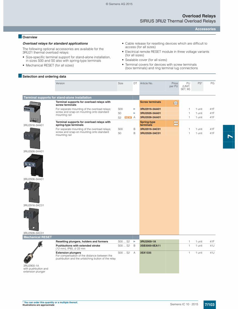
7/103Siemens IC 10 · 2015* You can order this quantity or a multiple thereof.Illustrations are approximate
Overload RelaysSIRIUS 3RU2 Thermal Overload Relays
Accessories
7
■ Overview
Overload relays for standard applications
The following optional accessories are available for the 3RU21 thermal overload relays:• Size-specific terminal support for stand-alone installation,
in sizes S00 and S0 also with spring-type terminals• Mechanical RESET (for all sizes)
• Cable release for resetting devices which are difficult to access (for all sizes)
• Electrical remote RESET module in three voltage variants (for all sizes)
• Sealable cover (for all sizes)• Terminal covers for devices with screw terminals
(box terminals) and ring terminal lug connections
■ Selection and ordering data
Version Size DT Article No. Priceper PU
PU(UNIT,
SET, M)
PS* PG
Terminal supports for stand-alone installation
3RU2916-3AA01
3RU2926-3AA01
3RU2936-3AA01
3RU2916-3AC01
3RU2926-3AC01
Terminal supports for overload relays with screw terminals
Screw terminals
For separate mounting of the overload relays; screw and snap-on mounting onto standard mounting rail
S00 } 3RU2916-3AA01 1 1 unit 41F
S0 } 3RU2926-3AA01 1 1 unit 41F
S2 A 3RU2936-3AA01 1 1 unit 41F
Terminal supports for overload relays with spring-type terminals
Spring-type terminals
For separate mounting of the overload relays; screw and snap-on mounting onto standard mounting rail
S00 B 3RU2916-3AC01 1 1 unit 41F
S0 B 3RU2926-3AC01 1 1 unit 41F
Mechanical RESET
3RU2900-1A with pushbutton and extension plunger
Resetting plungers, holders and formers S00 ... S2 } 3RU2900-1A 1 1 unit 41F
Pushbuttons with extended stroke (12 mm), IP65, ∅ 22 mm
S00 ... S2 B 3SB3000-0EA11 1 1 unit 41J
Extension plungers For compensation of the distance between the pushbutton and the unlatching button of the relay
S00 ... S2 A 3SX1335 1 1 unit 41J
© Siemens AG 2015
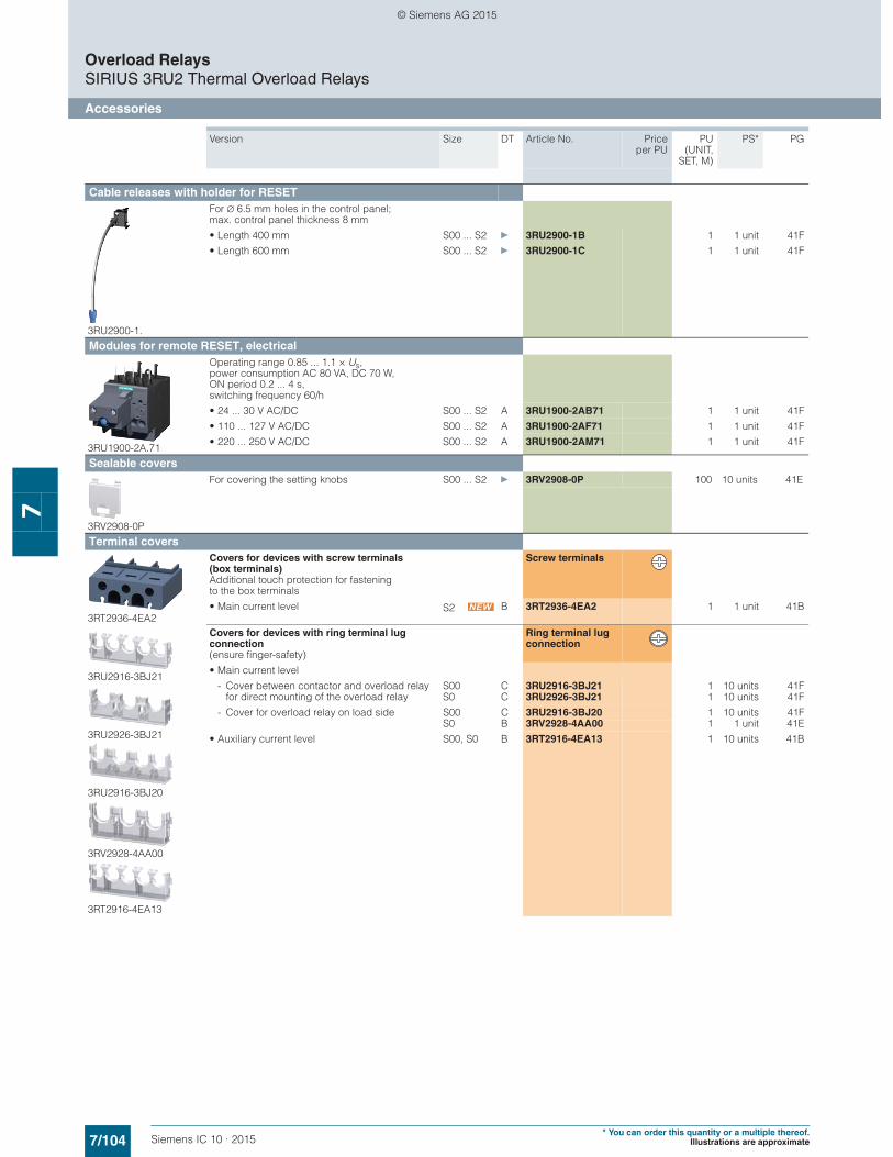
7/104 Siemens IC 10 · 2015* You can order this quantity or a multiple thereof.
Illustrations are approximate
Overload RelaysSIRIUS 3RU2 Thermal Overload Relays
Accessories
7
Cable releases with holder for RESET
3RU2900-1.
For ∅ 6.5 mm holes in the control panel; max. control panel thickness 8 mm
• Length 400 mm S00 ... S2 } 3RU2900-1B 1 1 unit 41F
• Length 600 mm S00 ... S2 } 3RU2900-1C 1 1 unit 41F
Modules for remote RESET, electrical
3RU1900-2A.71
Operating range 0.85 ... 1.1 × Us, power consumption AC 80 VA, DC 70 W, ON period 0.2 ... 4 s, switching frequency 60/h
• 24 ... 30 V AC/DC S00 ... S2 A 3RU1900-2AB71 1 1 unit 41F
• 110 ... 127 V AC/DC S00 ... S2 A 3RU1900-2AF71 1 1 unit 41F
• 220 ... 250 V AC/DC S00 ... S2 A 3RU1900-2AM71 1 1 unit 41F
Sealable covers
3RV2908-0P
For covering the setting knobs S00 ... S2 } 3RV2908-0P 100 10 units 41E
Terminal covers
3RT2936-4EA2
Covers for devices with screw terminals (box terminals)Additional touch protection for fasteningto the box terminals
Screw terminals
• Main current level S2 B 3RT2936-4EA2 1 1 unit 41B
3RU2916-3BJ21
3RU2926-3BJ21
3RU2916-3BJ20
3RV2928-4AA00
3RT2916-4EA13
Covers for devices with ring terminal lug connection (ensure finger-safety)
Ring terminal lug connection
• Main current level
- Cover between contactor and overload relay for direct mounting of the overload relay
S00 C 3RU2916-3BJ21 1 10 units 41FS0 C 3RU2926-3BJ21 1 10 units 41F
- Cover for overload relay on load side S00 C 3RU2916-3BJ20 1 10 units 41FS0 B 3RV2928-4AA00 1 1 unit 41E
• Auxiliary current level S00, S0 B 3RT2916-4EA13 1 10 units 41B
Version Size DT Article No. Priceper PU
PU(UNIT,
SET, M)
PS* PG
© Siemens AG 2015

7/105Siemens IC 10 · 2015* You can order this quantity or a multiple thereof.Illustrations are approximate
Overload RelaysSIRIUS 3RU2 Thermal Overload Relays
Accessories
7
General accessories
1) PC labeling system for individual inscriptionof unit labeling plates available from:murrplastik Systemtechnik GmbH(see Chapter 16, "Appendix" ➞ "External Partners").
■ More information
Manuals • System Manual "SIRIUS Innovations – System Overview"
http://support.automation.siemens.com/WW/view/en/60311318• Manual "SIRIUS Innovations – SIRIUS 3RU2/3RB3 Overload
Relays"http://support.automation.siemens.com/WW/view/en/60298164
Version Size Color For overload relays
DT Article No. Priceper PU
PU(UNIT,
SET, M)
PS* PG
Tools for opening spring-type terminals
3RA2908-1A
Spring-type terminals
Screwdrivers For all SIRIUS devices with spring-type terminals
Length approx. 200 mm, 3.0 mm x 0.5 mm
Titanium gray/black, partially insulated
Main and auxiliary circuit connection: 3RU2
A 3RA2908-1A 1 1 unit 41B
Blank labels
3RT1900-1SB20
Unit labeling plates1)
for SIRIUS devices20 mm x 7 mm Pastel
turquoise3RU2 D 3RT1900-1SB20 100 340 units 41B
3RT2900-1SB20
20 mm x 7 mm Titanium gray
3RU2 D 3RT2900-1SB20 100 340 units 41B
NSB
0_01
429b
IC01
_001
81
© Siemens AG 2015
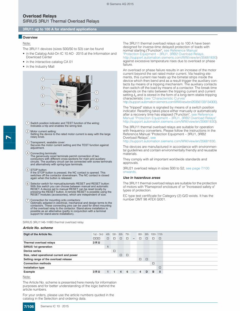
7/106 Siemens IC 10 · 2015
Overload RelaysSIRIUS 3RU1 Thermal Overload Relays
3RU11 up to 100 A for standard applications
7
■ Overview
Note:
The 3RU11 devices (sizes S00/S0 to S3) can be found• in the Catalog Add-On IC 10 AO · 2015 at the Information and
Download Center• in the interactive catalog CA 01• in the Industry Mall
SIRIUS 3RU1146-1HB0 thermal overload relay
The 3RU11 thermal overload relays up to 100 A have been designed for inverse-time delayed protection of loads with normal starting ("Function", see Reference Manual "Protection Equipment – 3RU1, 3RB2 Overload Relays, http://support.automation.siemens.com/WW/view/en/35681830) against excessive temperature rises due to overload or phase failure.
An overload or phase failure results in an increase of the motor current beyond the set rated motor current. Via heating ele-ments, this current rise heats up the bimetal strips inside the device which then bend and as a result trigger the auxiliary con-tacts by means of a tripping mechanism. The auxiliary contacts then switch off the load by means of a contactor. The break time depends on the ratio between the tripping current and current setting Ie and is stored in the form of a long-term stable tripping characteristic (see "Characteristic Curves" http://support.automation.siemens.com/WW/view/en/20356133/134300).
The "tripped" status is signaled by means of a switch position indicator. Resetting takes place either manually or automatically after a recovery time has elapsed ("Function", see Reference Manual "Protection Equipment – 3RU1, 3RB2 Overload Relays" http://support.automation.siemens.com/WW/view/en/35681830).
The 3RU11 thermal overload relays are suitable for operation with frequency converters. Please follow the instructions in the Reference Manual "Protection Equipment – 3RU1, 3RB2 Overload Relays", see http://support.automation.siemens.com/WW/view/en/35681830.
The devices are manufactured in accordance with environmen-tal guidelines and contain environmentally friendly and reusable materials.
They comply with all important worldwide standards and approvals.
3RU21 overload relays in sizes S00 to S2, see page 7/100 onwards.
Use in hazardous areas
The 3RU11 thermal overload relays are suitable for the protection of motors with "Flameproof enclosure d" or "Increased safety e" types of protection.
EC type test certificate for Category (2) G/D exists. It has the number DMT 98 ATEX G001.
Article No. scheme
Note:
The Article No. scheme is presented here merely for information purposes and for better understanding of the logic behind the article numbers.
For your orders, please use the article numbers quoted in the catalog in the Selection and ordering data.
6
5
4
7
2
1
3
Switch position indicator and TEST function of the wiring:Indicates a trip and enables the wiring test.
Motor current setting:Setting the device to the rated motor current is easy with the large rotary knob.
Transparent, sealable cover:Secures the motor current setting and the TEST function against adjustment.
Connecting terminals:The generously sized terminals permit connection of two conductors with different cross-sections for main and auxiliary circuits. The auxiliary circuit can be connected with screw terminals and alternatively with spring-type terminals.
STOP button:If the STOP button is pressed, the NC contact is opened. This switches off the contactor downstream. The NC contact is closed again when the button is released.
Selector switch for manual/automatic RESET and RESET button:With this switch you can choose between manual and automatic RESET. A device set to manual RESET can be reset locally by pressing the RESET button. A remote RESET is possible using the RESET modules (accessories), which are independent of size.
Connection for mounting onto contactors:Optimally adapted in electrical, mechanical and design terms to the contactors. These connecting pins can be used for direct mounting of the overload relay to the contactor. Stand-alone installation is possible as an alternative (partly in conjunction with a terminal support for stand-alone installation).
5
7
6
1
2
3
4
IC01
_003
34
Digit of the Article No. 1st - 3rd 4th 5th 6th 7th 8th 9th 10th 11th
@@@ @ @ @ @ – @ @ @ @
Thermal overload relays 3 R U
SIRIUS 1st generation 1
Device series @
Size, rated operational current and power @ @
Setting range of the overload release @ @
Connection methods @
Installation type @
Example 3 R U 1 1 4 6 – 4 D B 0
© Siemens AG 2015
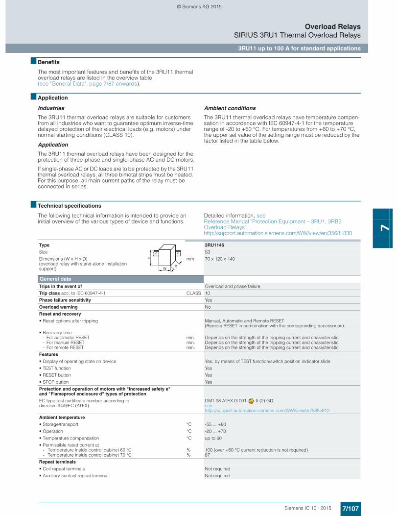
7/107Siemens IC 10 · 2015
Overload RelaysSIRIUS 3RU1 Thermal Overload Relays
3RU11 up to 100 A for standard applications
7
■ Benefits
The most important features and benefits of the 3RU11 thermal overload relays are listed in the overview table (see "General Data", page 7/87 onwards).
■ Application
Industries
The 3RU11 thermal overload relays are suitable for customers from all industries who want to guarantee optimum inverse-time delayed protection of their electrical loads (e.g. motors) under normal starting conditions (CLASS 10).
Application
The 3RU11 thermal overload relays have been designed for the protection of three-phase and single-phase AC and DC motors.
If single-phase AC or DC loads are to be protected by the 3RU11 thermal overload relays, all three bimetal strips must be heated. For this purpose, all main current paths of the relay must be connected in series.
Ambient conditions
The 3RU11 thermal overload relays have temperature compen-sation in accordance with IEC 60947-4-1 for the temperature range of -20 to +60 °C. For temperatures from +60 to +70 °C, the upper set value of the setting range must be reduced by the factor listed in the table below.
■ Technical specifications
The following technical information is intended to provide an initial overview of the various types of device and functions.
Detailed information, seeReference Manual "Protection Equipment – 3RU1, 3RB2 Overload Relays", http://support.automation.siemens.com/WW/view/en/35681830
Type 3RU1146
Size S3
Dimensions (W x H x D)(overload relay with stand-alone installation support)
mm 70 x 120 x 140
General dataTrips in the event of Overload and phase failure
Trip class acc. to IEC 60947-4-1 CLASS 10
Phase failure sensitivity Yes
Overload warning No
Reset and recovery
• Reset options after tripping Manual, Automatic and Remote RESET (Remote RESET in combination with the corresponding accessories)
• Recovery time- For automatic RESET min. Depends on the strength of the tripping current and characteristic- For manual RESET min. Depends on the strength of the tripping current and characteristic- For remote RESET min. Depends on the strength of the tripping current and characteristic
Features
• Display of operating state on device Yes, by means of TEST function/switch position indicator slide
• TEST function Yes
• RESET button Yes
• STOP button Yes
Protection and operation of motors with "Increased safety e" and "Flameproof enclosure d" types of protection
EC type test certificate number according to directive 94/9/EC (ATEX)
DMT 98 ATEX G 001 II (2) GD,see http://support.automation.siemens.com/WW/view/en/5355912
Ambient temperature
• Storage/transport °C -55 ... +80
• Operation °C -20 ... +70
• Temperature compensation °C up to 60
• Permissible rated current at- Temperature inside control cabinet 60 °C % 100 (over +60 °C current reduction is not required)- Temperature inside control cabinet 70 °C % 87
Repeat terminals
• Coil repeat terminals Not required
• Auxiliary contact repeat terminal Not required
W
H
D
© Siemens AG 2015
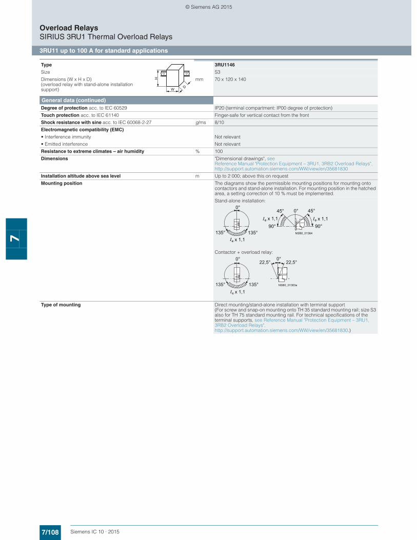
7/108 Siemens IC 10 · 2015
Overload RelaysSIRIUS 3RU1 Thermal Overload Relays
3RU11 up to 100 A for standard applications
7
General data (continued)Degree of protection acc. to IEC 60529 IP20 (terminal compartment: IP00 degree of protection)
Touch protection acc. to IEC 61140 Finger-safe for vertical contact from the front
Shock resistance with sine acc. to IEC 60068-2-27 g/ms 8/10
Electromagnetic compatibility (EMC)
• Interference immunity Not relevant
• Emitted interference Not relevant
Resistance to extreme climates – air humidity % 100
Dimensions "Dimensional drawings", see Reference Manual "Protection Equipment – 3RU1, 3RB2 Overload Relays", http://support.automation.siemens.com/WW/view/en/35681830
Installation altitude above sea level m Up to 2 000; above this on request
Mounting position The diagrams show the permissible mounting positions for mounting onto contactors and stand-alone installation. For mounting position in the hatched area, a setting correction of 10 % must be implemented.
Stand-alone installation:
Contactor + overload relay:
Type of mounting Direct mounting/stand-alone installation with terminal support (For screw and snap-on mounting onto TH 35 standard mounting rail; size S3 also for TH 75 standard mounting rail. For technical specifications of the terminal supports, see Reference Manual "Protection Equipment – 3RU1, 3RB2 Overload Relays", http://support.automation.siemens.com/WW/view/en/35681830.)
Type 3RU1146
Size S3
Dimensions (W x H x D)(overload relay with stand-alone installation support)
mm 70 x 120 x 140
W
H
D
x 1,1ex 1,1e
0°
90°90°
x 1,1e
45°
135°
45°0°
135° NSB0_01364
x 1,1
0°
e
135°
22,5°22,5°0°
135° NSB0_01363a
© Siemens AG 2015
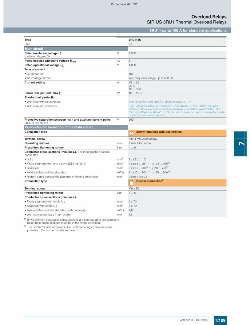
7/109Siemens IC 10 · 2015
Overload RelaysSIRIUS 3RU1 Thermal Overload Relays
3RU11 up to 100 A for standard applications
7
1) If two different conductor cross-sections are connected to one clamping point, both cross-sections must be in the range specified.
2) The box terminal is removable. Rail and cable lug connections are possible if the box terminal is removed.
Type 3RU1146
Size S3
Main circuitRated insulation voltage Ui (pollution degree 3)
V 1 000
Rated impulse withstand voltage Uimp kV 8
Rated operational voltage Ue V 1 000
Type of current
• Direct current Yes
• Alternating current Yes, frequency range up to 400 Hz
Current setting A 18 ... 25 up to 80 ... 100
Power loss per unit (max.) W 10 ... 16.5
Short-circuit protection
• With fuse without contactor See "Selection and ordering data" on page 7/111
• With fuse and contactor See Reference Manual "Protection Equipment – 3RU1, 3RB2 Overload Relays", http://support.automation.siemens.com/WW/view/en/35681830 ➞ "Technical Specifications" ➞ "Short-circuit protection with fuses/motor starter protectors for motor feeders".
Protective separation between main and auxiliary current paths acc. to IEC 60947-1
V 690
Conductor cross-section of the main circuitConnection type Screw terminals with box terminal
Terminal screw M8, 4 mm Allen screw
Operating devices mm 4 mm Allen screw
Prescribed tightening torque Nm 4 ... 6
Conductor cross-sections (min./max.), 1 or 2 conductors can be connected
• Solid mm2 2 x (2.5 ... 16)
• Finely stranded with end sleeve (DIN 46228-1) mm2 2 x (2.5 ... 35)1), 1 x (2.5 ... 50)1)
• Stranded mm2 2 x (10 ... 50)1), 1 x (10 ... 70)1)
• AWG cables, solid or stranded AWG 2 x (10 ... 1/0)1), 1 x (10 ... 2/0)1)
• Ribbon cable conductors (Number x Width x Thickness) mm 2 x (6 x 9 x 0.8)
Connection type Busbar connection2)
Terminal screw M6 x 20
Prescribed tightening torque Nm 4 ... 6
Conductor cross-sections (min./max.)
• Finely stranded with cable lug mm2 2 x 70
• Stranded with cable lug mm2 3 x 70
• AWG cables, solid or stranded, with cable lug AWG 2/0
• With connecting bars (max. width) mm 12
© Siemens AG 2015
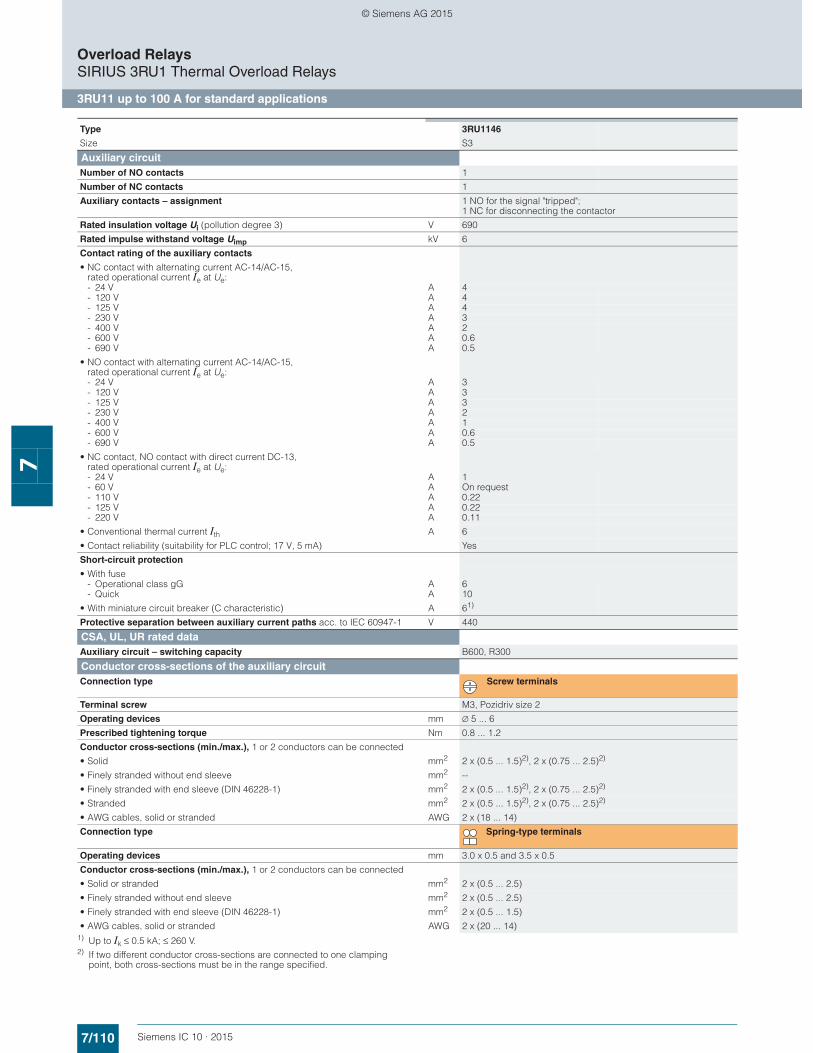
7/110 Siemens IC 10 · 2015
Overload RelaysSIRIUS 3RU1 Thermal Overload Relays
3RU11 up to 100 A for standard applications
7
1) Up to Ik ≤ 0.5 kA; ≤ 260 V.2) If two different conductor cross-sections are connected to one clamping
point, both cross-sections must be in the range specified.
Type 3RU1146
Size S3
Auxiliary circuitNumber of NO contacts 1
Number of NC contacts 1
Auxiliary contacts – assignment 1 NO for the signal "tripped"; 1 NC for disconnecting the contactor
Rated insulation voltage Ui (pollution degree 3) V 690
Rated impulse withstand voltage Uimp kV 6
Contact rating of the auxiliary contacts
• NC contact with alternating current AC-14/AC-15,rated operational current Ie at Ue:- 24 V A 4- 120 V A 4- 125 V A 4- 230 V A 3- 400 V A 2- 600 V A 0.6- 690 V A 0.5
• NO contact with alternating current AC-14/AC-15,rated operational current Ie at Ue:- 24 V A 3- 120 V A 3- 125 V A 3- 230 V A 2- 400 V A 1- 600 V A 0.6- 690 V A 0.5
• NC contact, NO contact with direct current DC-13, rated operational current Ie at Ue:- 24 V A 1- 60 V A On request- 110 V A 0.22- 125 V A 0.22- 220 V A 0.11
• Conventional thermal current Ith A 6
• Contact reliability (suitability for PLC control; 17 V, 5 mA) Yes
Short-circuit protection
• With fuse- Operational class gG A 6- Quick A 10
• With miniature circuit breaker (C characteristic) A 61)
Protective separation between auxiliary current paths acc. to IEC 60947-1 V 440
CSA, UL, UR rated dataAuxiliary circuit – switching capacity B600, R300
Conductor cross-sections of the auxiliary circuitConnection type Screw terminals
Terminal screw M3, Pozidriv size 2
Operating devices mm ∅ 5 ... 6
Prescribed tightening torque Nm 0.8 ... 1.2
Conductor cross-sections (min./max.), 1 or 2 conductors can be connected
• Solid mm2 2 x (0.5 ... 1.5)2), 2 x (0.75 ... 2.5)2)
• Finely stranded without end sleeve mm2 --
• Finely stranded with end sleeve (DIN 46228-1) mm2 2 x (0.5 ... 1.5)2), 2 x (0.75 ... 2.5)2)
• Stranded mm2 2 x (0.5 ... 1.5)2), 2 x (0.75 ... 2.5)2)
• AWG cables, solid or stranded AWG 2 x (18 ... 14)
Connection type Spring-type terminals
Operating devices mm 3.0 x 0.5 and 3.5 x 0.5
Conductor cross-sections (min./max.), 1 or 2 conductors can be connected
• Solid or stranded mm2 2 x (0.5 ... 2.5)
• Finely stranded without end sleeve mm2 2 x (0.5 ... 2.5)
• Finely stranded with end sleeve (DIN 46228-1) mm2 2 x (0.5 ... 1.5)
• AWG cables, solid or stranded AWG 2 x (20 ... 14)
© Siemens AG 2015
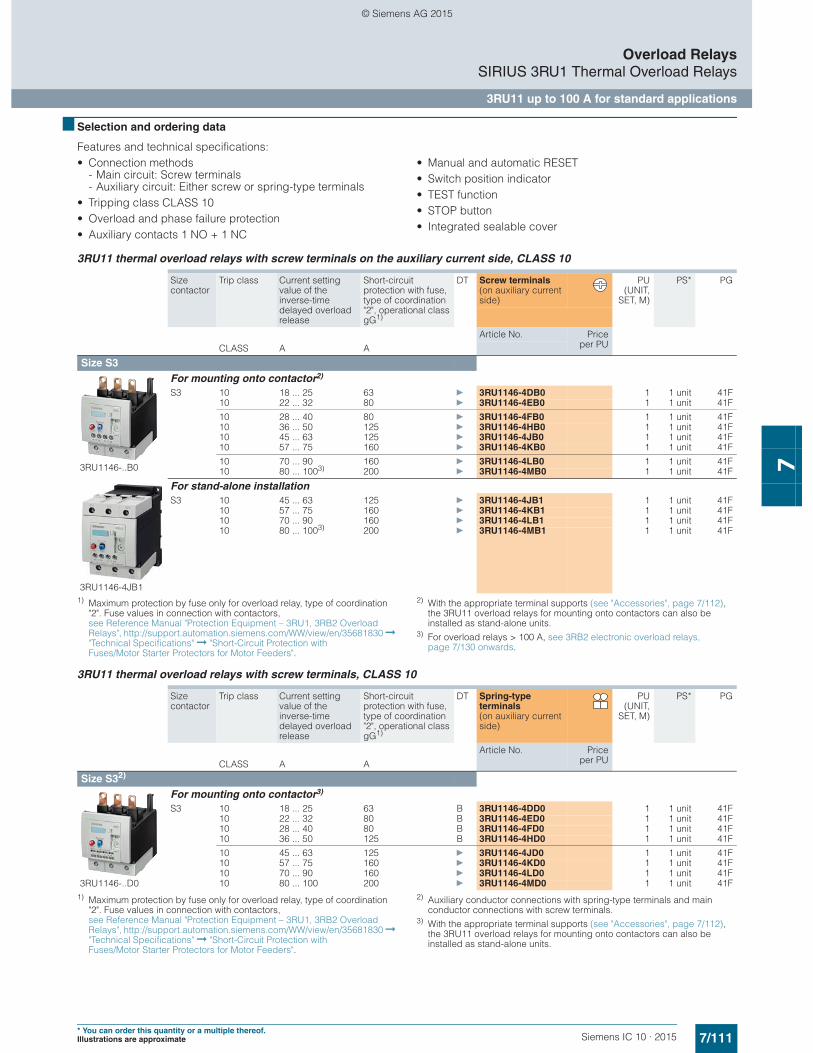
7/111Siemens IC 10 · 2015* You can order this quantity or a multiple thereof.Illustrations are approximate
Overload RelaysSIRIUS 3RU1 Thermal Overload Relays
3RU11 up to 100 A for standard applications
7
■ Selection and ordering data
Features and technical specifications: • Connection methods
- Main circuit: Screw terminals- Auxiliary circuit: Either screw or spring-type terminals
• Tripping class CLASS 10• Overload and phase failure protection• Auxiliary contacts 1 NO + 1 NC
• Manual and automatic RESET• Switch position indicator• TEST function• STOP button• Integrated sealable cover
3RU11 thermal overload relays with screw terminals on the auxiliary current side, CLASS 10
1) Maximum protection by fuse only for overload relay, type of coordination "2". Fuse values in connection with contactors, see Reference Manual "Protection Equipment – 3RU1, 3RB2 Overload Relays", http://support.automation.siemens.com/WW/view/en/35681830 ➞ "Technical Specifications" ➞ "Short-Circuit Protection with Fuses/Motor Starter Protectors for Motor Feeders".
2) With the appropriate terminal supports (see "Accessories", page 7/112), the 3RU11 overload relays for mounting onto contactors can also be installed as stand-alone units.
3) For overload relays > 100 A, see 3RB2 electronic overload relays, page 7/130 onwards.
3RU11 thermal overload relays with screw terminals, CLASS 10
1) Maximum protection by fuse only for overload relay, type of coordination "2". Fuse values in connection with contactors, see Reference Manual "Protection Equipment – 3RU1, 3RB2 Overload Relays", http://support.automation.siemens.com/WW/view/en/35681830 ➞ "Technical Specifications" ➞ "Short-Circuit Protection with Fuses/Motor Starter Protectors for Motor Feeders".
2) Auxiliary conductor connections with spring-type terminals and main conductor connections with screw terminals.
3) With the appropriate terminal supports (see "Accessories", page 7/112), the 3RU11 overload relays for mounting onto contactors can also be installed as stand-alone units.
Size contactor
Trip class Current setting value of the inverse-time delayed overload release
Short-circuit protection with fuse, type of coordination "2", operational class gG1)
DT Screw terminals (on auxiliary current side)
PU(UNIT,
SET, M)
PS* PG
Article No. Priceper PUCLASS A A
Size S3
3RU1146-..B0
For mounting onto contactor2)
S3 10 18 ... 25 63 } 3RU1146-4DB0 1 1 unit 41F10 22 ... 32 80 } 3RU1146-4EB0 1 1 unit 41F
10 28 ... 40 80 } 3RU1146-4FB0 1 1 unit 41F10 36 ... 50 125 } 3RU1146-4HB0 1 1 unit 41F10 45 ... 63 125 } 3RU1146-4JB0 1 1 unit 41F10 57 ... 75 160 } 3RU1146-4KB0 1 1 unit 41F
10 70 ... 90 160 } 3RU1146-4LB0 1 1 unit 41F10 80 ... 1003) 200 } 3RU1146-4MB0 1 1 unit 41F
3RU1146-4JB1
For stand-alone installationS3 10 45 ... 63 125 } 3RU1146-4JB1 1 1 unit 41F
10 57 ... 75 160 } 3RU1146-4KB1 1 1 unit 41F10 70 ... 90 160 } 3RU1146-4LB1 1 1 unit 41F10 80 ... 1003) 200 } 3RU1146-4MB1 1 1 unit 41F
Size contactor
Trip class Current setting value of the inverse-time delayed overload release
Short-circuit protection with fuse, type of coordination "2", operational class gG1)
DT Spring-type terminals (on auxiliary current side)
PU(UNIT,
SET, M)
PS* PG
Article No. Priceper PUCLASS A A
Size S32)
3RU1146-..D0
For mounting onto contactor3)
S3 10 18 ... 25 63 B 3RU1146-4DD0 1 1 unit 41F10 22 ... 32 80 B 3RU1146-4ED0 1 1 unit 41F10 28 ... 40 80 B 3RU1146-4FD0 1 1 unit 41F10 36 ... 50 125 B 3RU1146-4HD0 1 1 unit 41F
10 45 ... 63 125 } 3RU1146-4JD0 1 1 unit 41F10 57 ... 75 160 } 3RU1146-4KD0 1 1 unit 41F10 70 ... 90 160 } 3RU1146-4LD0 1 1 unit 41F10 80 ... 100 200 } 3RU1146-4MD0 1 1 unit 41F
© Siemens AG 2015

7/112 Siemens IC 10 · 2015* You can order this quantity or a multiple thereof.
Illustrations are approximate
Overload RelaysSIRIUS 3RU1 Thermal Overload Relays
Accessories
7
■ Overview
Overload relays for standard applications
The following optional accessories are available for the 3RU11 thermal overload relays:• Terminal supports for stand-alone installation for the overload
relays• Mechanical RESET (for all sizes)
• Cable release for resetting devices which are difficult to access (for all sizes)
• Electrical remote RESET module in three voltage variants (for all sizes)
• Terminal covers
■ Technical specifications
Terminal supports for stand-alone installation
1) If two different conductor cross-sections are connected to one clamping point, both cross-sections must be in the range specified.
■ Selection and ordering data
Type 3RU1946-3AA01
For overload relays 3RU1146
Mounting type For screw and snap-on mounting onto TH 35 and TH 75 standard mounting rails
Connection for main circuitConnection type Screw terminals with box terminal
Terminal screw mm 4 mm Allen screw
Operating devices mm 4 mm Allen screw
Prescribed tightening torque Nm 4 ... 6
Conductor cross-sections (min./max.), 1 or 2 conductors can be connected
• Solid or stranded mm2 2 x (2.5 ... 16)
• Finely stranded without end sleeve mm2 --
• Finely stranded with end sleeve (DIN 46228-1) mm2 2 x (2.5 ... 35)1), 1 x (2.5 ... 50)1)
• Stranded mm2 2 x (10 ... 50)1), 1 x (10 ... 70)1)
• AWG cables, solid or stranded AWG 2 x (10 ... 1/0)1), 1 x (10 ... 2/0)1)
• Ribbon cable conductors (Number x Width x Thickness) mm 2 x (6 x 9 x 0.8)
Version Size DT Article No. Priceper PU
PU(UNIT,
SET, M)
PS* PG
Terminal supports for stand-alone installation
3RU19.6-3AA01
For separate mounting of the overload relays; screw and snap-on mounting onto standard mounting rail
S3 } 3RU1946-3AA01 1 1 unit 41F
Mechanical RESET
3RU1900-1A with pushbutton and extension plunger
Resetting plungers, holders and formers S3 } 3RU1900-1A 1 1 unit 41F
Pushbuttons with extended stroke (12 mm), IP65, ∅ 22 mm
S3 B 3SB3000-0EA11 1 1 unit 41J
Extension plungers For compensation of the distance between the pushbutton and the unlatching button of the relay
S3 A 3SX1335 1 1 unit 41J
© Siemens AG 2015
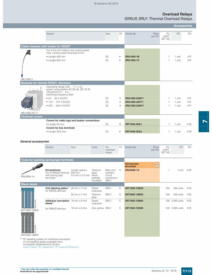
7/113Siemens IC 10 · 2015* You can order this quantity or a multiple thereof.Illustrations are approximate
Overload RelaysSIRIUS 3RU1 Thermal Overload Relays
Accessories
7
General accessories
1) PC labeling system for individual inscriptionof unit labeling plates available from:murrplastik Systemtechnik GmbH(see Chapter 16, "Appendix" ➞ "External Partners").
Version Size DT Article No. Priceper PU
PU(UNIT,
SET, M)
PS* PG
Cable releases with holder for RESET
3RU1900-1.
For ∅ 6.5 mm holes in the control panel; max. control panel thickness 8 mm
• Length 400 mm S3 } 3RU1900-1B 1 1 unit 41F
• Length 600 mm S3 } 3RU1900-1C 1 1 unit 41F
Modules for remote RESET, electrical
3RU1900-2A.71
Operating range 0.85 ... 1.1 × Us, power consumption AC 80 VA, DC 70 W, ON period 0.2 ... 4 s, switching frequency 60/h
• 24 ... 30 V AC/DC S3 A 3RU1900-2AB71 1 1 unit 41F
• 110 ... 127 V AC/DC S3 A 3RU1900-2AF71 1 1 unit 41F
• 220 ... 250 V AC/DC S3 A 3RU1900-2AM71 1 1 unit 41F
Terminal covers Covers for cable lugs and busbar connections
• Length 55 mm S3 B 3RT1946-4EA1 1 1 unit 41B
Covers for box terminals
• Length 20.8 mm S3 } 3RT1946-4EA2 1 1 unit 41B
Version Size Color For overload relays
DT Article No. Priceper PU
PU(UNIT,
SET, M)
PS* PG
Tools for opening spring-type terminals
3RA2908-1A
Spring-type terminals
Screwdrivers For all SIRIUS devices with spring-type terminals
Length approx. 200 mm, 3.0 mm x 0.5 mm
Titanium gray/black, partially insulated
Main and auxiliary circuit connection: 3RU1
A 3RA2908-1A 1 1 unit 41B
Blank labels
3RT1900-1SB20
3RT2900-1SB20
Unit labeling plates1)
for SIRIUS devices20 mm x 7 mm Pastel
turquoise3RU1 D 3RT1900-1SB20 100 340 units 41B
20 mm x 7 mm Titanium gray
3RU1 D 3RT2900-1SB20 100 340 units 41B
Adhesive inscriptionlabels1)
for SIRIUS devices
19 mm x 6 mm Pastel turquoise
3RU1 C 3RT1900-1SB60 100 3 060 units 41B
19 mm x 6 mm Zinc yellow 3RU1 C 3RT1900-1SD60 100 3 060 units 41BNSB
0_01
429b
IC01
_001
81
© Siemens AG 2015

7/114 Siemens IC 10 · 2015
Overload RelaysSIRIUS 3RB3 Electronic Overload Relays
3RB30, 3RB31 up to 80 A for standard applications
7
■ Overview
SIRIUS 3RU3133-4.B0 electronic overload relay
The 3RB30/3RB31 electronic overload relays up to 80 A with internal power supply have been designed for inverse-time delayed protection of loads with normal and heavy starting (for "Function", see the manual "SIRIUS Innovations – SIRIUS 3RU2/3RB3 Overload Relays", http://support.automation.siemens.com/WW/view/en/60298164) against excessive temperature rises due to overload, phase unbalance or phase failure. An overload, phase unbalance or phase failure result in an increase of the motor current beyond the set rated motor current. This current rise is detected by the current transformers integrated into the devices and evaluated by corresponding solid-state circuits which then output a pulse to the auxiliary contacts. The auxiliary contacts then switch off the load by means of a contactor. The break time depends on the ratio between the tripping current and current setting Ie and is stored in the form of a long-term stable tripping characteristic (see "Characteristic Curves" http://support.automation.siemens.com/WW/view/en/34290881/134300).
In addition to inverse-time delayed protection of loads against excessive temperature rises due to overload, phase unbalance and phase failure, the 3RB31 electronic overload relays also allow internal ground-fault detection (not possible in conjunction with contactor assemblies for wye-delta starting). This provides protection of loads against high-resistance short circuits due to damage to the insulation material, moisture, condensed water etc.
The "tripped" status is signaled by means of a switch position indicator. Resetting takes place either manually or automatically after the recovery time has elapsed ("Function", see manual "SIRIUS Innovations – SIRIUS 3RU2/3RB3 Overload Relays", http://support.automation.siemens.com/WW/view/en/60298164).
The 3RB3 electronic overload relays are suitable for operation with frequency converters. Please follow the instructions in the manual "SIRIUS Innovations – 3RU2/3RB3 Overload Relays", see http://support.automation.siemens.com/WW/view/en/60298164.
The devices are manufactured in accordance with environmen-tal guidelines and contain environmentally friendly and reusable materials. They comply with all important worldwide standards and approvals.
3RB20 and 3RB21 overload relays in sizes S2 to S10/S12, see page 7/130 onwards.
Use in hazardous areas
The 3RB30/3RB31 electronic overload relays are suitable for the overload protection of motors with the following types of protection:• II (2) G [Ex e] [Ex d] [Ex px]• II (2) D [Ex t] [Ex p]
EC type test certificate for Group II, Category (2) G/D exists. It has the number PTB 09 ATEX 3001.
8
5
6
71
4
3
2
A sealable transparent cover can be optionally mounted (accessory). It secures the motor current setting against adjustment.
Connection for mounting onto contactors: Optimally adapted in electrical, mechanical and design terms to the contactors 3RT2. The overload relay can be connected directly using these connection pins. Stand-alone installation is possible as an alternative (in conjunction with a terminal support forstand-alone installation).
8
Selector switch for manual/automatic RESET: With the slide switch you can choose between manual and automatic RESET.
5
Indicates a trip and enables the wiring test.Switch position indicator and TEST function of the wiring: 1
Solid-state test (device test): Enables a test of all important device components and functions.
3
Motor current setting: Setting the device to the rated motor current is easy with the large rotary knob.
6
Trip class setting/internal ground-fault detection (only 3RB31): Using the rotary switch you can set the required trip class and activate the internal ground-fault detection dependent on the start-up conditions.
2
Connecting terminals (removable joint block for auxiliary circuits): Depending on the device version, the terminals for screw and spring-type connection are configured for the main and auxiliary circuit.
4
A device set to manual RESET can be reset locally by pressing the RESET button. On 3RB31 overload relays an electrical remote RESET is integrated.
7
IC01
_004
06
© Siemens AG 2015
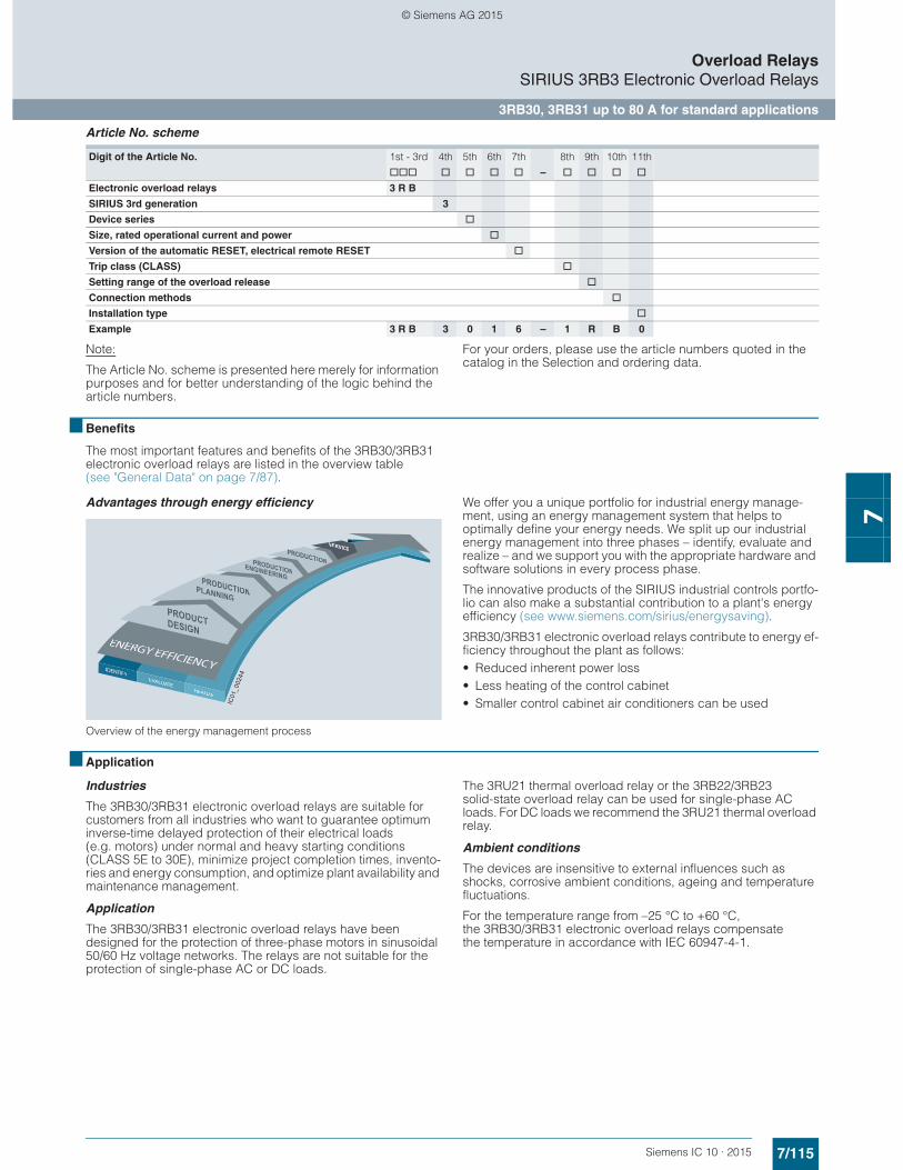
7/115Siemens IC 10 · 2015
Overload RelaysSIRIUS 3RB3 Electronic Overload Relays
3RB30, 3RB31 up to 80 A for standard applications
7
Article No. scheme
Note:
The Article No. scheme is presented here merely for information purposes and for better understanding of the logic behind the article numbers.
For your orders, please use the article numbers quoted in the catalog in the Selection and ordering data.
■ Benefits
The most important features and benefits of the 3RB30/3RB31 electronic overload relays are listed in the overview table (see "General Data" on page 7/87).
Advantages through energy efficiency
Overview of the energy management process
We offer you a unique portfolio for industrial energy manage-ment, using an energy management system that helps to optimally define your energy needs. We split up our industrial energy management into three phases – identify, evaluate and realize – and we support you with the appropriate hardware and software solutions in every process phase.
The innovative products of the SIRIUS industrial controls portfo-lio can also make a substantial contribution to a plant's energy efficiency (see www.siemens.com/sirius/energysaving).
3RB30/3RB31 electronic overload relays contribute to energy ef-ficiency throughout the plant as follows:• Reduced inherent power loss • Less heating of the control cabinet • Smaller control cabinet air conditioners can be used
■ Application
Industries
The 3RB30/3RB31 electronic overload relays are suitable for customers from all industries who want to guarantee optimum inverse-time delayed protection of their electrical loads (e.g. motors) under normal and heavy starting conditions (CLASS 5E to 30E), minimize project completion times, invento-ries and energy consumption, and optimize plant availability and maintenance management.
Application
The 3RB30/3RB31 electronic overload relays have been designed for the protection of three-phase motors in sinusoidal 50/60 Hz voltage networks. The relays are not suitable for the protection of single-phase AC or DC loads.
The 3RU21 thermal overload relay or the 3RB22/3RB23 solid-state overload relay can be used for single-phase AC loads. For DC loads we recommend the 3RU21 thermal overload relay.
Ambient conditions
The devices are insensitive to external influences such as shocks, corrosive ambient conditions, ageing and temperature fluctuations.
For the temperature range from –25 °C to +60 °C, the 3RB30/3RB31 electronic overload relays compensate the temperature in accordance with IEC 60947-4-1.
Digit of the Article No. 1st - 3rd 4th 5th 6th 7th 8th 9th 10th 11th
@@@ @ @ @ @ – @ @ @ @
Electronic overload relays 3 R B
SIRIUS 3rd generation 3
Device series @
Size, rated operational current and power @
Version of the automatic RESET, electrical remote RESET @
Trip class (CLASS) @
Setting range of the overload release @
Connection methods @
Installation type @
Example 3 R B 3 0 1 6 – 1 R B 0
IC01
_002
44
© Siemens AG 2015

7/116 Siemens IC 10 · 2015
Overload RelaysSIRIUS 3RB3 Electronic Overload Relays
3RB30, 3RB31 up to 80 A for standard applications
7
■ Technical specifications
The following technical information is intended to provide an initial overview of the various types of device and functions.
Detailed information, see • Manual "SIRIUS Innovations – SIRIUS 3RU2/3RB3 Overload
Relays", http://support.automation.siemens.com/WW/view/en/60298164
• or specific information on a particular article number via the product data sheet, http://support.automation.siemens.com/WW/view/en/34290881/133200
Type 3RB301., 3RB311. 3RB302., 3RB312. 3RB3036, 3RB3133
Size S00 S0 S2
Dimensions (W x H x D)(overload relay with stand-alone installation support)• Screw terminals• Spring-type terminals
mmmm
45 x 89 x 8045 x 102 x 80
45 x 97 x 9445 x 116 x 95
55 x 105 x 11755 x 105 x 117
General data Trips in the event of Overload, phase failure, and phase unbalance
+ ground fault (for 3RB31 only)
Trip class acc. to IEC 60947-4-1 CLASS 3RB30: 10E, 20E; 3RB31: 5E, 10E, 20E or 30E adjustable
Phase failure sensitivity Yes
Reset and recovery
• Reset options after tripping Manual and automatic RESET, 3RB31 has an integrated connection for electrical remote RESET (24 V DC)
• Recovery time- For automatic RESET Approx. 3 min- For manual RESET Immediately- For remote RESET Immediately
Features
• Display of operating state on device Yes, by means of switch position indicator slide
• TEST function Yes, test of electronics by pressing the TEST button/test of auxiliary contacts and wiring of control circuit by actuating the switch position indicator slide/self-monitoring
• RESET button Yes
• STOP button No
Protection and operation of explosion-proof motors
EC type test certificate number according to directive 94/9/EC (ATEX)
PTB 09 ATEX 3001 II (2) G [Ex e] [Ex d] [Ex px]
II (2) G [Ex t] [Ex p]
See http://support.automation.siemens.com/WW/view/en/40591327
On request
Ambient temperatures
• Storage/transport °C -40 ... +80
• Operation °C -25 ... +60
• Temperature compensation °C +60
• Permissible rated current at- Temperature inside control cabinet 60 °C % 100- Temperature inside control cabinet 70 °C % On request
Repeat terminals
• Coil repeat terminals Yes Not required
• Auxiliary contact repeat terminal Yes Not required
Degree of protection acc. to IEC 60529 IP20
Touch protection acc. to IEC 61140 Finger-safe for vertical contact from the front
Shock resistance with sine acc. to IEC 60068-2-27 g/ms 15/11 (signaling contact 97/98 in "Tripped" position: 9 g/11 ms)
15/11 (signaling contact 97/98 in "Tripped" position: 8 g/11 ms)
Electromagnetic compatibility (EMC) – Interference immunity
• Conductor-related interference- Burst acc. to IEC 61000-4-4
(corresponds to degree of severity 3)kV 2 (power ports), 1 (signal ports)
- Surge acc. to IEC 61000-4-5 (corresponds to degree of severity 3)
kV 2 (line to earth), 1 (line to line)
• Electrostatic discharge according to IEC 61000-4-2 (corresponds to degree of severity 3)
kV 8 (air discharge), 6 (contact discharge)
• Field-related interference acc. to IEC 61000-4-3 (corresponds to degree of severity 3)
V/m 10
Electromagnetic compatibility (EMC) – emitted interference Degree of severity B acc. to EN 55011 (CISPR 11) and EN 55022 (CISPR 22)
Resistance to extreme climates – air humidity % 95
WH
D
© Siemens AG 2015

7/117Siemens IC 10 · 2015
Overload RelaysSIRIUS 3RB3 Electronic Overload Relays
3RB30, 3RB31 up to 80 A for standard applications
7
1) If two different conductor cross-sections are connected to one clamping point, both cross-sections must be in the range specified.
General data (continued) Dimensions "Dimensional drawings", see
• Manual "SIRIUS Innovations – SIRIUS 3RU2/3RB3 Overload Relays", http://support.automation.siemens.com/WW/view/en/60298164
• Product data sheet, http://support.automation.siemens.com/WW/view/en/34290881/133200
Installation altitude above sea level m Up to 2 000
Mounting position Any
Type of mounting Direct mounting/stand-alone installation with terminal support
Type 3RB301., 3RB311. 3RB302., 3RB312. 3RB3036, 3RB3133
Size S00 S0 S2
Dimensions (W x H x D)(overload relay with stand-alone installation support)• Screw terminals• Spring-type terminals
mmmm
45 x 89 x 8045 x 102 x 80
45 x 97 x 9445 x 116 x 95
55 x 105 x 11755 x 105 x 117
W
H
D
Type 3RB301., 3RB311. 3RB302., 3RB312. 3RB3036, 3RB3133
Size S00 S0 S2
Main circuitRated insulation voltage Ui (pollution degree 3)
V 690
Rated impulse withstand voltage Uimp kV 6
Rated operational voltage Ue V 690
Type of current• Direct current No• Alternating current Yes, 50/60 Hz ± 5 %
Current setting A
A
0.1 ... 0.4 up to 4 ... 16
0.1 ... 0.4 up to 10 ... 40
12.5 ... 50 and20 to 80
Heavy starting See Manual "SIRIUS Innovations – SIRIUS 3RU2/3RB3 Overload Relays", http://support.automation.siemens.com/WW/view/en/60298164
Power loss per unit (max.) W 0.05 ... 0.2
Short-circuit protection• With fuse without contactor See "Selection and ordering data" on pages 7/119 to 7/121• With fuse and contactor "Short-Circuit Protection with Fuses/Motor Starter Protectors for Motor
Feeders", see Configuration Manual for "Configuring SIRIUS Innovations – Selection Data for Fuseless and Fused Load Feeders", http://support.automation.siemens.com/WW/view/en/39714188.
Protective separation between main and auxiliary current paths acc. to IEC 60947-1 (pollution degree 2)• For systems with grounded neutral point V 690• For systems with ungrounded neutral point V 600
Conductor cross-sections of main circuitConnection type Screw terminals
Terminal screw M3, Pozidriv size 2 M4, Pozidriv size 2
Operating devices mm ∅ 5 ... 6 ∅ 5 ... 6
Prescribed tightening torque Nm 0.8 ... 1.2 2 ... 2.5
Conductor cross-sections (min./max.), 1 or 2 conductors can be connected• Solid or stranded mm2 2 x (0.5 ... 1.5)1),
2 x (0.75 ... 2.5)1), 2 x (0.5 ... 4)1)
2 x (1 ... 2.5)1), 2 x (2.5 ... 10)1)
1 x (1 ... 50)1), 2 x (1 ... 35)1)
• Finely stranded with end sleeve (DIN 46228-1) mm2 2 x (0.5 ... 1.5)1), 2 x (0.75 ... 2.5)1)
2 x (1 ... 2.5)1), 2 x (2.5 ... 6)1), max. 1 x 10
2 x (1 ... 25)1), 1 x (1 ... 35)1)
• AWG cables, solid or stranded AWG 2 x (20 ... 16)1), 2 x (18 ... 14)1),2 x 12
2 x (16 ... 12)1), 2 x (14 ... 8)1)
2 x (18 ... 2)1), 1 x (18 ... 1)1)
Connection type Spring-type terminals
Operating devices mm 3.0 x 0.5 and 3.5 x 0.5
Conductor cross-sections (min./max.), 1 conductor can be connected• Solid or stranded mm2 1 x (0.5 ... 4) 1 x (1 ... 10) --• Finely stranded without end sleeve mm2 1 x (0.5 ... 2.5) 1 x (1 ... 6) --• Finely stranded with end sleeve (DIN 46228-1) mm2 1 x (0.5 ... 2.5) 1 x (1 ... 6) --• AWG cables, solid or stranded AWG 1 x (20 ... 12) 1 x (18 ... 8) --
Connection type Straight-through transformers
Diameter of opening mm -- 15
© Siemens AG 2015

7/118 Siemens IC 10 · 2015
Overload RelaysSIRIUS 3RB3 Electronic Overload Relays
3RB30, 3RB31 up to 80 A for standard applications
7
1) If two different conductor cross-sections are connected to one clamping point, both cross-sections must be in the range specified.
Type 3RB301., 3RB311. 3RB302., 3RB312. 3RB3036, 3RB3133
Size S00 S0 S2
Auxiliary circuitNumber of NO contacts 1
Number of NC contacts 1
Auxiliary contacts – assignment 1 NO for the signal "tripped"; 1 NC for disconnecting the contactor
Rated insulation voltage Ui (pollution degree 3) V 300
Rated impulse withstand voltage Uimp kV 4
Auxiliary contacts – contact rating
• NC contact with alternating current AC-14/AC-15, rated operational current Ie at Ue:- 24 V A 4- 120 V A 4- 125 V A 4- 250 V A 3
• NO contact with alternating current AC-14/AC-15, rated operational current Ie at Ue:- 24 V A 4- 120 V A 4- 125 V A 4- 250 V A 3
• NC contact, NO contact with direct current DC-13, rated operational current Ie at Ue:- 24 V A 2- 60 V A 0.55- 110 V A 0.3- 125 V A 0.3- 250 V A 0.11
• Conventional thermal current Ith A 5
• Contact reliability (suitability for PLC control; 17 V, 5 mA) Yes
Short-circuit protection
• With fuse, operational class gG A 6
Ground-fault protection (only 3RB31) The information refers to sinusoidal residual currents at 50/60 Hz.
• Tripping value IΔ > 0.75 × Imotor
• Operating range I Lower current setting value < Imotor < 3.5 × upper current setting value• Response time ttrip (in steady-state condition) s < 1
Integrated electrical remote RESET (only 3RB31)
Connecting terminals A3, A4 24 V DC, max. 200 mA for approx. 20 ms, then < 10 mA
Protective separation between auxiliary current paths acc. to IEC 60947-1
V 300
CSA, UL, UR rated dataAuxiliary circuit – switching capacity 3RB30: B600, R300; 3RB31: B300, R300
Conductor cross-sections for auxiliary circuitConnection type Screw terminals
Terminal screw M3, Pozidriv size 2
Operating devices mm ∅ 5 ... 6
Prescribed tightening torque Nm 0.8 ... 1.2
Conductor cross-sections (min./max.), 1 or 2 conductors can be connected
• Solid or stranded mm2 1 × (0.5 ... 4)1), 2 × (0.5 ... 2.5)1)
• Finely stranded with end sleeve (DIN 46228-1) mm2 1 × (0.5 ... 2.5)1), 2 × (0.5 ... 1.5)1)
• AWG cables, solid or stranded AWG 2 × (20 ... 14)
Connection type Spring-type terminals
Operating devices mm 3.0 x 0.5
Conductor cross-sections (min./max.), 1 or 2 conductors can be connected
• Solid or stranded mm2 2 × (0.25 ... 1.5)
• Finely stranded without end sleeve mm2 2 × (0.25 ... 1.5)
• Finely stranded with end sleeve (DIN 46228-1) mm2 2 × (0.25 ... 1.5)
• AWG cables, solid or stranded AWG 2 × (24 ... 16)
© Siemens AG 2015

7/119Siemens IC 10 · 2015* You can order this quantity or a multiple thereof.Illustrations are approximate
Overload RelaysSIRIUS 3RB3 Electronic Overload Relays
3RB30, 3RB31 up to 80 A for standard applications
7
■ Selection and ordering data
3RB30 electronic overload relays, CLASS 10E
Features and technical specifications:• Connection methods
- Sizes S00 and S0: Main and auxiliary circuit: Either screw or spring-type terminals
- Size S2:Main circuit: Screw terminals with box terminal or as straight-through transformer,auxiliary circuit: Either screw or spring-type terminals
• Overload protection, phase failure protection and unbalance protection
• Internal power supply• Auxiliary contacts 1 NO + 1 NC
• Manual and automatic RESET• Switch position indicator• TEST function and self-monitoring• Sealable covers (optional accessory)
PU (UNIT, SET, M) = 1PS* = 1 unitPG = 41G
1) Maximum protection by fuse only for overload relay, type of coordination "2". Fuse values in connection with contactors, see Configuration Manual "Configuring SIRIUS Innovations – Selection Data for Fuseless and Fused Load Feeders"http://support.automation.siemens.com/WW/view/en/39714188.
2) With the appropriate terminal supports (see "Accessories", page 7/122), these overload relays can also be installed as stand-alone units.
Size contactor2)
Trip class Current setting value of the inverse-time delayed overload release
Short-circuit protection with fuse, type of coordination "2", operational class gG1)
DT Screw terminals DT Spring-type terminals
Article No. Priceper PU
Article No. Priceper PUCLASS A A
Size S00S00 Devices for mounting onto contactor2)
10E 0.1 … 0.4 4 } 3RB3016-1RB0 A 3RB3016-1RE0
10E 0.32 … 1.25 6 } 3RB3016-1NB0 A 3RB3016-1NE0
10E 1 … 4 20 } 3RB3016-1PB0 A 3RB3016-1PE0
10E 3 … 12 25 } 3RB3016-1SB0 A 3RB3016-1SE0
10E 4 ... 16 25 } 3RB3016-1TB0 A 3RB3016-1TE0
Size S0S0 Devices for mounting onto contactor2)
10E 0.1 … 0.4 4 } 3RB3026-1RB0 A 3RB3026-1RE0
10E 0.32 … 1.25 6 } 3RB3026-1NB0 A 3RB3026-1NE0
10E 1 … 4 20 } 3RB3026-1PB0 A 3RB3026-1PE0
10E 3 … 12 25 } 3RB3026-1SB0 A 3RB3026-1SE0
10E 6 … 25 50 } 3RB3026-1QB0 A 3RB3026-1QE0
10E 10 ... 40 50 } 3RB3026-1VB0 A 3RB3026-1VE0
Size S2S2 Devices with screw terminals (main current side) and
for mounting onto contactor2)
10E 12 ... 50 250 A 3RB3036-1UB0 A 3RB3036-1UD0
10E 20 ... 80 250 A 3RB3036-1WB0 A 3RB3036-1WD0
Devices with straight-through transformer for stand-alone installation10E 12 ... 50 250 A 3RB3036-1UW1 A 3RB3036-1UX1
10E 20 ... 80 250 A 3RB3036-1WW1 A 3RB3036-1WX1
3RB3016-1TB0 3RB3016-1TE03RB3026-1VB0 3RB3026-1VE03RB3036-1.B0 3RB3036-1.W1 3RB3036-1.X13RB3036-1.D0
© Siemens AG 2015
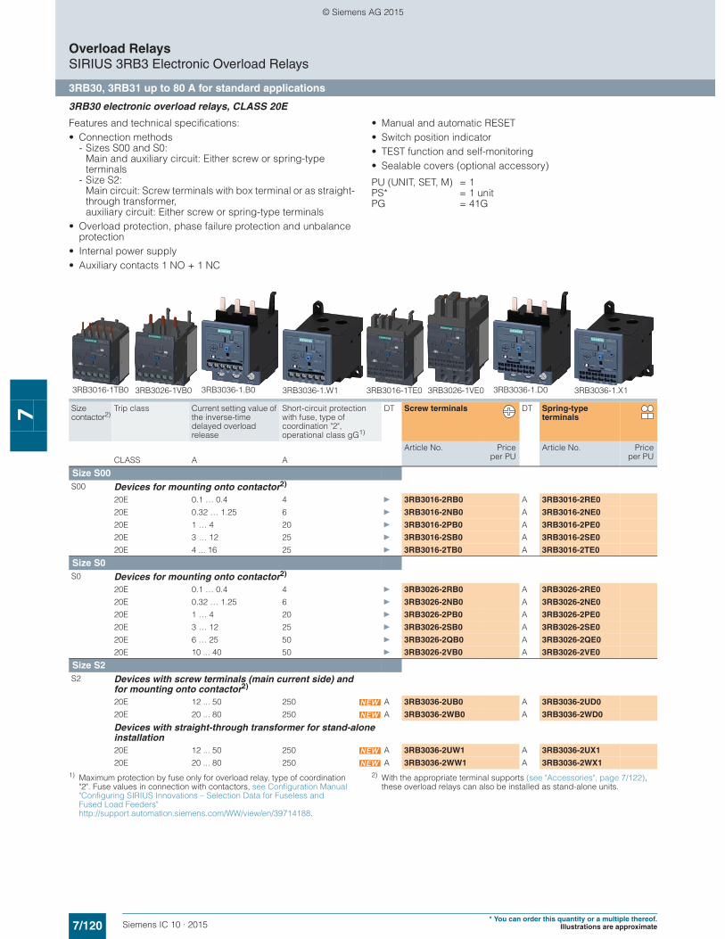
7/120 Siemens IC 10 · 2015* You can order this quantity or a multiple thereof.
Illustrations are approximate
Overload RelaysSIRIUS 3RB3 Electronic Overload Relays
3RB30, 3RB31 up to 80 A for standard applications
7
3RB30 electronic overload relays, CLASS 20E
Features and technical specifications:• Connection methods
- Sizes S00 and S0: Main and auxiliary circuit: Either screw or spring-type terminals
- Size S2:Main circuit: Screw terminals with box terminal or as straight-through transformer,auxiliary circuit: Either screw or spring-type terminals
• Overload protection, phase failure protection and unbalance protection
• Internal power supply• Auxiliary contacts 1 NO + 1 NC
• Manual and automatic RESET• Switch position indicator• TEST function and self-monitoring• Sealable covers (optional accessory)
PU (UNIT, SET, M) = 1PS* = 1 unitPG = 41G
1) Maximum protection by fuse only for overload relay, type of coordination "2". Fuse values in connection with contactors, see Configuration Manual "Configuring SIRIUS Innovations – Selection Data for Fuseless and Fused Load Feeders" http://support.automation.siemens.com/WW/view/en/39714188.
2) With the appropriate terminal supports (see "Accessories", page 7/122), these overload relays can also be installed as stand-alone units.
Size contactor2)
Trip class Current setting value of the inverse-time delayed overload release
Short-circuit protection with fuse, type of coordination "2", operational class gG1)
DT Screw terminals DT Spring-type terminals
Article No. Priceper PU
Article No. Priceper PUCLASS A A
Size S00S00 Devices for mounting onto contactor2)
20E 0.1 … 0.4 4 } 3RB3016-2RB0 A 3RB3016-2RE0
20E 0.32 … 1.25 6 } 3RB3016-2NB0 A 3RB3016-2NE0
20E 1 … 4 20 } 3RB3016-2PB0 A 3RB3016-2PE0
20E 3 … 12 25 } 3RB3016-2SB0 A 3RB3016-2SE0
20E 4 ... 16 25 } 3RB3016-2TB0 A 3RB3016-2TE0
Size S0S0 Devices for mounting onto contactor2)
20E 0.1 … 0.4 4 } 3RB3026-2RB0 A 3RB3026-2RE0
20E 0.32 … 1.25 6 } 3RB3026-2NB0 A 3RB3026-2NE0
20E 1 … 4 20 } 3RB3026-2PB0 A 3RB3026-2PE0
20E 3 … 12 25 } 3RB3026-2SB0 A 3RB3026-2SE0
20E 6 … 25 50 } 3RB3026-2QB0 A 3RB3026-2QE0
20E 10 ... 40 50 } 3RB3026-2VB0 A 3RB3026-2VE0
Size S2S2 Devices with screw terminals (main current side) and
for mounting onto contactor2)
20E 12 ... 50 250 A 3RB3036-2UB0 A 3RB3036-2UD0
20E 20 ... 80 250 A 3RB3036-2WB0 A 3RB3036-2WD0
Devices with straight-through transformer for stand-alone installation20E 12 ... 50 250 A 3RB3036-2UW1 A 3RB3036-2UX1
20E 20 ... 80 250 A 3RB3036-2WW1 A 3RB3036-2WX1
3RB3016-1TB0 3RB3016-1TE03RB3026-1VB0 3RB3026-1VE03RB3036-1.B0 3RB3036-1.W1 3RB3036-1.X13RB3036-1.D0
© Siemens AG 2015
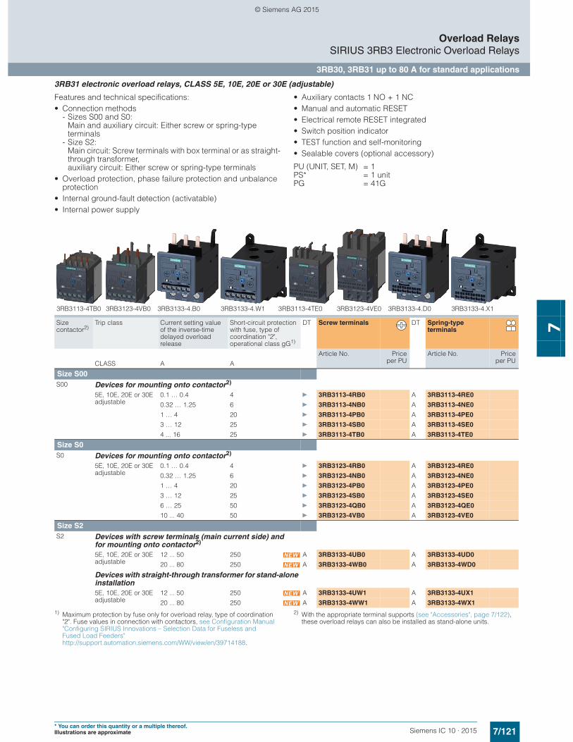
7/121Siemens IC 10 · 2015* You can order this quantity or a multiple thereof.Illustrations are approximate
Overload RelaysSIRIUS 3RB3 Electronic Overload Relays
3RB30, 3RB31 up to 80 A for standard applications
7
3RB31 electronic overload relays, CLASS 5E, 10E, 20E or 30E (adjustable)
Features and technical specifications:• Connection methods
- Sizes S00 and S0: Main and auxiliary circuit: Either screw or spring-type terminals
- Size S2:Main circuit: Screw terminals with box terminal or as straight-through transformer,auxiliary circuit: Either screw or spring-type terminals
• Overload protection, phase failure protection and unbalance protection
• Internal ground-fault detection (activatable)• Internal power supply
• Auxiliary contacts 1 NO + 1 NC• Manual and automatic RESET• Electrical remote RESET integrated• Switch position indicator• TEST function and self-monitoring• Sealable covers (optional accessory)
PU (UNIT, SET, M) = 1PS* = 1 unitPG = 41G
1) Maximum protection by fuse only for overload relay, type of coordination "2". Fuse values in connection with contactors, see Configuration Manual "Configuring SIRIUS Innovations – Selection Data for Fuseless and Fused Load Feeders" http://support.automation.siemens.com/WW/view/en/39714188.
2) With the appropriate terminal supports (see "Accessories", page 7/122), these overload relays can also be installed as stand-alone units.
Size contactor2)
Trip class Current setting value of the inverse-time delayed overload release
Short-circuit protection with fuse, type of coordination "2", operational class gG1)
DT Screw terminals DT Spring-type terminals
Article No. Priceper PU
Article No. Priceper PUCLASS A A
Size S00S00 Devices for mounting onto contactor2)
5E, 10E, 20E or 30E adjustable
0.1 … 0.4 4 } 3RB3113-4RB0 A 3RB3113-4RE0
0.32 … 1.25 6 } 3RB3113-4NB0 A 3RB3113-4NE0
1 … 4 20 } 3RB3113-4PB0 A 3RB3113-4PE0
3 … 12 25 } 3RB3113-4SB0 A 3RB3113-4SE0
4 ... 16 25 } 3RB3113-4TB0 A 3RB3113-4TE0
Size S0S0 Devices for mounting onto contactor2)
5E, 10E, 20E or 30E adjustable
0.1 … 0.4 4 } 3RB3123-4RB0 A 3RB3123-4RE0
0.32 … 1.25 6 } 3RB3123-4NB0 A 3RB3123-4NE0
1 … 4 20 } 3RB3123-4PB0 A 3RB3123-4PE0
3 … 12 25 } 3RB3123-4SB0 A 3RB3123-4SE0
6 … 25 50 } 3RB3123-4QB0 A 3RB3123-4QE0
10 ... 40 50 } 3RB3123-4VB0 A 3RB3123-4VE0
Size S2S2 Devices with screw terminals (main current side) and
for mounting onto contactor2)
5E, 10E, 20E or 30E adjustable
12 ... 50 250 A 3RB3133-4UB0 A 3RB3133-4UD0
20 ... 80 250 A 3RB3133-4WB0 A 3RB3133-4WD0
Devices with straight-through transformer for stand-alone installation5E, 10E, 20E or 30E adjustable
12 ... 50 250 A 3RB3133-4UW1 A 3RB3133-4UX1
20 ... 80 250 A 3RB3133-4WW1 A 3RB3133-4WX1
3RB3123-4VB0 3RB3123-4VE03RB3113-4TB0 3RB3113-4TE03RB3133-4.B0 3RB3133-4.W1 3RB3133-4.D0 3RB3133-4.X1
© Siemens AG 2015
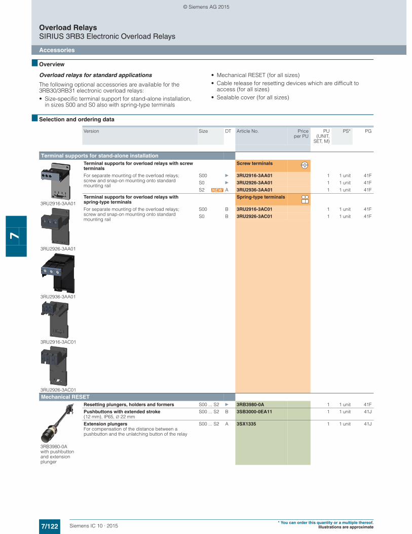
7/122 Siemens IC 10 · 2015* You can order this quantity or a multiple thereof.
Illustrations are approximate
Overload RelaysSIRIUS 3RB3 Electronic Overload Relays
Accessories
7
■ Overview
Overload relays for standard applications
The following optional accessories are available for the 3RB30/3RB31 electronic overload relays:• Size-specific terminal support for stand-alone installation,
in sizes S00 and S0 also with spring-type terminals
• Mechanical RESET (for all sizes)• Cable release for resetting devices which are difficult to
access (for all sizes)• Sealable cover (for all sizes)
■ Selection and ordering data
Version Size DT Article No. Priceper PU
PU(UNIT,
SET, M)
PS* PG
Terminal supports for stand-alone installation
3RU2916-3AA01
3RU2926-3AA01
3RU2936-3AA01
3RU2916-3AC01
3RU2926-3AC01
Terminal supports for overload relays with screw terminals
Screw terminals
For separate mounting of the overload relays; screw and snap-on mounting onto standard mounting rail
S00 } 3RU2916-3AA01 1 1 unit 41F
S0 } 3RU2926-3AA01 1 1 unit 41F
S2 A 3RU2936-3AA01 1 1 unit 41F
Terminal supports for overload relays with spring-type terminals
Spring-type terminals
For separate mounting of the overload relays; screw and snap-on mounting onto standard mounting rail
S00 B 3RU2916-3AC01 1 1 unit 41F
S0 B 3RU2926-3AC01 1 1 unit 41F
Mechanical RESET
3RB3980-0A with pushbutton and extension plunger
Resetting plungers, holders and formers S00 ... S2 } 3RB3980-0A 1 1 unit 41F
Pushbuttons with extended stroke (12 mm), IP65, ∅ 22 mm
S00 ... S2 B 3SB3000-0EA11 1 1 unit 41J
Extension plungersFor compensation of the distance between a pushbutton and the unlatching button of the relay
S00 ... S2 A 3SX1335 1 1 unit 41J
© Siemens AG 2015
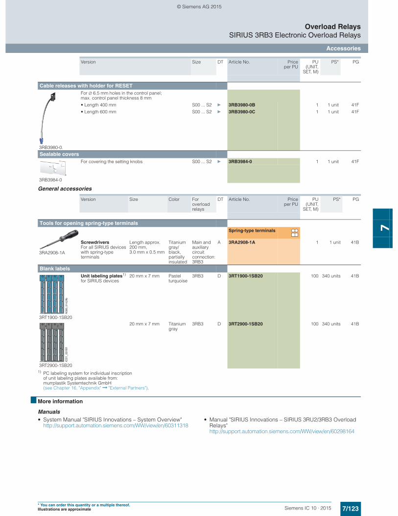
7/123Siemens IC 10 · 2015* You can order this quantity or a multiple thereof.Illustrations are approximate
Overload RelaysSIRIUS 3RB3 Electronic Overload Relays
Accessories
7
General accessories
1) PC labeling system for individual inscriptionof unit labeling plates available from:murrplastik Systemtechnik GmbH(see Chapter 16, "Appendix" ➞ "External Partners").
■ More information
Manuals • System Manual "SIRIUS Innovations – System Overview"
http://support.automation.siemens.com/WW/view/en/60311318• Manual "SIRIUS Innovations – SIRIUS 3RU2/3RB3 Overload
Relays"http://support.automation.siemens.com/WW/view/en/60298164
Cable releases with holder for RESET
3RB3980-0.
For ∅ 6.5 mm holes in the control panel; max. control panel thickness 8 mm
• Length 400 mm S00 ... S2 } 3RB3980-0B 1 1 unit 41F
• Length 600 mm S00 ... S2 } 3RB3980-0C 1 1 unit 41F
Sealable covers
3RB3984-0
For covering the setting knobs S00 ... S2 } 3RB3984-0 1 1 unit 41F
Version Size Color For overload relays
DT Article No. Priceper PU
PU(UNIT,
SET, M)
PS* PG
Tools for opening spring-type terminals
3RA2908-1A
Spring-type terminals
Screwdrivers For all SIRIUS devices with spring-type terminals
Length approx. 200 mm, 3.0 mm x 0.5 mm
Titanium gray/black, partially insulated
Main and auxiliary circuit connection: 3RB3
A 3RA2908-1A 1 1 unit 41B
Blank labels
3RT1900-1SB20
Unit labeling plates1)
for SIRIUS devices20 mm x 7 mm Pastel
turquoise3RB3 D 3RT1900-1SB20 100 340 units 41B
3RT2900-1SB20
20 mm x 7 mm Titanium gray
3RB3 D 3RT2900-1SB20 100 340 units 41B
Version Size DT Article No. Priceper PU
PU(UNIT,
SET, M)
PS* PGNSB
0_01
429b
IC01
_001
81
© Siemens AG 2015

7/124 Siemens IC 10 · 2015
Overload RelaysSIRIUS 3RB2 Electronic Overload Relays
3RB20, 3RB21 up to 630 A for standard applications
7
■ Overview
Note:
The 3RB20 and 3RB21 devices (sizes S00/S0 to S12) can be found• in the Catalog Add-On IC 10 AO · 2015 at the Information and
Download Center• in the interactive catalog CA 01• in the Industry Mall
SIRIUS 3RB2143-4ED0 electronic overload relay
The 3RB20 and 3RB21 electronic overload relays up to 630 A with internal power supply have been designed for inverse-time delayed protection of loads with normal and heavy starting ("Function", see Reference Manual "Protection Equipment – 3RU1, 3RB2 Overload Relays" http://support.automation.siemens.com/WW/view/en/35681297) against excessive temperature rises due to overload, phase unbalance or phase failure.
An overload, phase unbalance or phase failure result in an increase of the motor current beyond the set rated motor current. This current rise is detected by the current transformers inte-grated into the devices and evaluated by corresponding solid-state circuits which then output a pulse to the auxiliary contacts. The auxiliary contacts then switch off the load by means of a contactor. The break time depends on the ratio between the trip-ping current and current setting Ie and is stored in the form of a long-term stable tripping characteristic (see "Characteristic Curves" http://support.automation.siemens.com/WW/view/en/20357046/134300).
In addition to inverse-time delayed protection of loads against excessive temperature rises due to overload, phase unbalance and phase failure, the 3RB21 electronic overload relays also allow internal ground-fault detection (not possible in conjunction with contactor assemblies for wye-delta starting). This provides protection of loads against high-resistance short circuits due to damage to the insulation material, moisture, condensed water etc.
The "tripped" status is signaled by means of a switch position indicator. Resetting takes place either manually or automatically after the recovery time has elapsed ("Function", see Reference Manual "Protection Equipment – 3RU1, 3RB2 Overload Relays", http://support.automation.siemens.com/WW/view/en/35681297).
The 3RB2 electronic overload relays are suitable for operation with frequency converters. Please follow the instructions in the Reference Manual "Protection Equipment – 3RU1 and 3RB2 Overload Relays", see http://support.automation.siemens.com/WW/view/en/35681297.
The devices are manufactured in accordance with environmen-tal guidelines and contain environmentally friendly and reusable materials. They comply with all important worldwide standards and approvals.
For 3RB30 and 3RB31 overload relay sizes S00 to S2, see page 7/119 onwards.
Use in hazardous areas
The 3RB20/3RB21 electronic overload relays are suitable for the overload protection of motors with the following types of protection:• II (2) G [Ex e] [Ex d] [Ex px]• II (2) D [Ex t] [Ex p]
EC type test certificate for Group II, Category (2) G/D exists. It has the number PTB 06 ATEX 3001.
Connection for mounting onto contactors:Optimally adapted in electrical, mechanical and design terms to the contactors 3RT1. These connecting pins can be used for direct mounting of the overload relay to the contactor. Stand-alone installation is possible as an alternative (partly in conjunction with a terminal bracket for stand-alone installation).
Selector switch for manual/automatic RESET:With the slide switch you can choose between manual and automatic RESET.
5
Switch position indicator and TEST function of the wiring:Indicates a trip and enables the wiring test.
1
Solid-state test (device test):Enables a test of all important device components and functions.
3
Motor current setting:Setting the device to the rated motor current is easy with the large rotary knob.
6
Trip class setting/internal ground-fault detection (only 3RB21):Using the rotary switch you can set the required trip class and activate the internal ground-fault detection dependent on the start-up conditions.
2
Connecting terminals (removable terminal block for auxiliary circuits):The generously sized terminals permit connection of two conductors with different cross-sections for the main and auxiliary circuits. The auxiliary circuit can be connected with screw terminals and alternatively with spring-type terminals.
4
A device set to manual RESET can be reset locally by pressing the RESET button. On the 3RB21 overload relay a solid-state remote RESET is integrated.
7
8
7
6
5
1
2
3
4
IC01
_003
35
© Siemens AG 2015
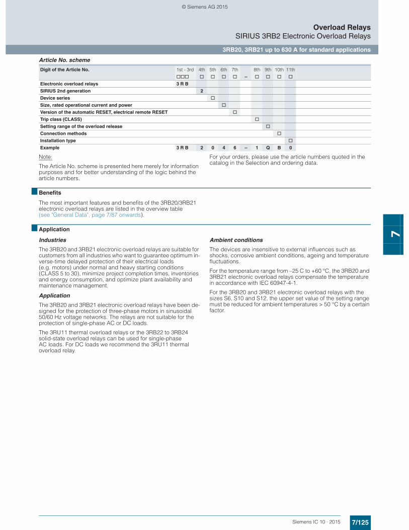
7/125Siemens IC 10 · 2015
Overload RelaysSIRIUS 3RB2 Electronic Overload Relays
3RB20, 3RB21 up to 630 A for standard applications
7
Article No. scheme
Note:
The Article No. scheme is presented here merely for information purposes and for better understanding of the logic behind the article numbers.
For your orders, please use the article numbers quoted in the catalog in the Selection and ordering data.
■ Benefits
The most important features and benefits of the 3RB20/3RB21 electronic overload relays are listed in the overview table (see "General Data", page 7/87 onwards).
■ Application
Industries
The 3RB20 and 3RB21 electronic overload relays are suitable for customers from all industries who want to guarantee optimum in-verse-time delayed protection of their electrical loads (e.g. motors) under normal and heavy starting conditions (CLASS 5 to 30), minimize project completion times, inventories and energy consumption, and optimize plant availability and maintenance management.
Application
The 3RB20 and 3RB21 electronic overload relays have been de-signed for the protection of three-phase motors in sinusoidal 50/60 Hz voltage networks. The relays are not suitable for the protection of single-phase AC or DC loads.
The 3RU11 thermal overload relays or the 3RB22 to 3RB24 solid-state overload relays can be used for single-phase AC loads. For DC loads we recommend the 3RU11 thermal overload relay.
Ambient conditions
The devices are insensitive to external influences such as shocks, corrosive ambient conditions, ageing and temperature fluctuations.
For the temperature range from –25 C to +60 °C, the 3RB20 and 3RB21 electronic overload relays compensate the temperature in accordance with IEC 60947-4-1.
For the 3RB20 and 3RB21 electronic overload relays with the sizes S6, S10 and S12, the upper set value of the setting range must be reduced for ambient temperatures > 50 °C by a certain factor.
Digit of the Article No. 1st - 3rd 4th 5th 6th 7th 8th 9th 10th 11th
@@@ @ @ @ @ – @ @ @ @
Electronic overload relays 3 R B
SIRIUS 2nd generation 2
Device series @
Size, rated operational current and power @
Version of the automatic RESET, electrical remote RESET @
Trip class (CLASS) @
Setting range of the overload release @
Connection methods @
Installation type @
Example 3 R B 2 0 4 6 – 1 Q B 0
© Siemens AG 2015

7/126 Siemens IC 10 · 2015
Overload RelaysSIRIUS 3RB2 Electronic Overload Relays
3RB20, 3RB21 up to 630 A for standard applications
7
■ Technical specifications
The following technical information is intended to provide an initial overview of the various types of device and functions.
Detailed information, see Reference Manual "Protection Equipment - Overload Relays 3RU1, 3RB2", http://support.automation.siemens.com/WW/view/en/35681297
1) 90 % for relay with current setting range 160 A to 630 A.
Type 3RB2046, 3RB2143 3RB2056, 3RB2153 3RB2066, 3RB2163Size S3 S6 S10/S12Dimensions (W x H x D)(overload relay with stand-alone installation support)
mm 70 x 86 x 124 120 x 119 x 155 145 x 147 x 156
General dataTrips in the event of Overload, phase failure, and phase unbalance
+ ground fault (for 3RB21 only)Trip class acc. to IEC 60947-4-1 CLASS 3RB20: 10 or 20;
3RB21: 5, 10, 20 and 30 adjustablePhase failure sensitivity YesOverload warning NoReset and recovery• Reset options after tripping 3RB20: Manual and automatic RESET;
3RB21: Manual, automatic and remote RESET• Recovery time
- For automatic RESET Approx. 3 min - For manual RESET Immediately- For remote RESET Immediately
Features• Display of operating state on device Yes, by means of switch position indicator slide• TEST function Yes, test of electronics by pressing the TEST button/
test of auxiliary contacts and wiring of control circuit by actuating the switch position indicator slide/self-monitoring
• RESET button Yes• STOP button NoProtection and operation of explosion-proof motorsEC type test certificate number according to directive 94/9/EC (ATEX)
PTB 06 ATEX 3001 II (2) G [Ex e] [Ex d] [Ex px]
II (2) G [Ex t] [Ex p]
see http://support.automation.siemens.com/WW/view/en/23814648Ambient temperatures• Storage/transport °C -40 ... +80• Operation °C -25 ... +60• Temperature compensation °C +60• Permissible rated current at
- Temperature inside control cabinet 60 °C, stand-alone installation
% 100 100 100 or 901)
- Temperature inside control cabinet 60 °C, mounted on contactor
% 100 70 70
- Temperature inside control cabinet 70 °C % On requestDegree of protection acc. to IEC 60529 IP20 IP20
(terminal compartment: IP00 degree of protection)Touch protection acc. to IEC 61140 Finger-safe for vertical
contact from the frontFinger-safe; for busbar connection with cover
Finger-safe with cover
Shock resistance with sine acc. to IEC 60068-2-27 g/ms 15/11 (signaling contact 97/98 in position "tripped": 4 g/11 ms)Electromagnetic compatibility (EMC) – Interference immunity • Conductor-related interference
- Burst acc. to IEC 61000-4-4 (corresponds to degree of severity 3)
kV 2 (power ports), 1 (signal ports)
- Surge acc. to IEC 61000-4-5 (corresponds to degree of severity 3)
kV 2 (line to earth), 1 (line to line)
• Electrostatic discharge according to IEC 61000-4-2 (corresponds to degree of severity 3)
kV 8 (air discharge), 6 (contact discharge)
• Field-related interference acc. to IEC 61000-4-3 (corresponds to degree of severity 3)
V/m 10
Electromagnetic compatibility (EMC) – emitted interference Degree of severity B acc. to EN 55011 (CISPR 11) and EN 55022 (CISPR 22)Resistance to extreme climates – air humidity % 100Dimensions "Dimensional drawings", see
Reference Manual "Protection Equipment - Overload Relays 3RU1, 3RB2",http://support.automation.siemens.com/WW/view/en/35681297
Installation altitude above sea level m Up to 2 000Mounting position AnyType of mounting Direct mounting/stand-alone
installation with terminal support
Direct mounting/stand-alone installation
W
H
D
© Siemens AG 2015
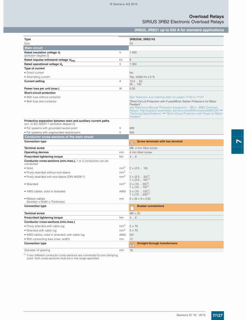
7/127Siemens IC 10 · 2015
Overload RelaysSIRIUS 3RB2 Electronic Overload Relays
3RB20, 3RB21 up to 630 A for standard applications
7
1) If two different conductor cross-sections are connected to one clamping point, both cross-sections must be in the range specified.
Type 3RB2046, 3RB2143
Size S3
Main circuitRated insulation voltage Ui (pollution degree 3)
V 1 000
Rated impulse withstand voltage Uimp kV 8
Rated operational voltage Ue V 1 000
Type of current
• Direct current No
• Alternating current Yes, 50/60 Hz ± 5 %
Current setting A 12.5 ... 50, 25 ... 100
Power loss per unit (max.) W 0.05
Short-circuit protection
• With fuse without contactor See "Selection and ordering data" on pages 7/130 to 7/132
• With fuse and contactor "Short-Circuit Protection with Fuses/Motor Starter Protectors for Motor Feeders", see Reference Manual "Protection Equipment – 3RU1, 3RB2 Overload Relays", http://support.automation.siemens.com/WW/view/en/35681297 ➞ "Technical Specifications" ➞ "Short-Circuit Protection with Fuses for Motor Feeders"
Protective separation between main and auxiliary current paths acc. to IEC 60947-1 (pollution degree 2)
• For systems with grounded neutral point V 690
• For systems with ungrounded neutral point V 600
Conductor cross-sections of the main circuitConnection type Screw terminals with box terminal
Terminal screw M8, 4 mm Allen screw
Operating devices mm 4 mm Allen screw
Prescribed tightening torque Nm 4 ... 6
Conductor cross-sections (min./max.), 1 or 2 conductors can be connected
• Solid mm2 2 × (2.5 ... 16)
• Finely stranded without end sleeve mm2 --
• Finely stranded with end sleeve (DIN 46228-1) mm2 2 × (2.5 ... 35)1), 1 × (2.5 ... 50)1)
• Stranded mm2 2 × (10 ... 50)1),1 × (10 ... 70)1)
• AWG cables, solid or stranded AWG 2 × (10 ... 1/0)1), 1 × (10 ... 2/0)1)
• Ribbon cables (Number x Width x Thickness)
mm 2 × (6 × 9 × 0.8)
Connection type Busbar connections
Terminal screw M6 × 20
Prescribed tightening torque Nm 4 ... 6
Conductor cross-sections (min./max.)
• Finely stranded with cable lug mm2 2 × 70
• Stranded with cable lug mm2 3 × 70
• AWG cables, solid or stranded, with cable lug AWG 2/0
• With connecting bars (max. width) mm 12
Connection type Straight-through transformers
Diameter of opening mm 18
© Siemens AG 2015

7/128 Siemens IC 10 · 2015
Overload RelaysSIRIUS 3RB2 Electronic Overload Relays
3RB20, 3RB21 up to 630 A for standard applications
7
1) When connecting cable lugs according to DIN 46235 with conductor cross-sections of 95 mm2 and more, the 3RT1956-4EA1 terminal cover must be used to ensure phase clearance.
2) When connecting cable lugs according to DIN 46234 with conductor cross-sections of 240 mm2 and more as well as to DIN 46235 with conduc-tor cross-sections of 185 mm2 and more, the 3RT1956-4EA1 terminal cover must be used to ensure the phase clearance.
Type 3RB2056, 3RB2153 3RB2066, 3RB2163
Size S6 S10/S12
Main circuitRated insulation voltage Ui (pollution degree 3) V 1 000
Rated impulse withstand voltage Uimp kV 8
Rated operational voltage Ue V 1 000
Type of current
• Direct current No• Alternating current Yes, 50/60 Hz ± 5 %
Current setting A 50 ... 200 55 ... 250,160 ... 630
Power loss per unit (max.) W 0.05
Short-circuit protection
• With fuse without contactor See "Selection and ordering data" on pages 7/130 to 7/132• With fuse and contactor "Short-Circuit Protection with Fuses/Motor Starter Protectors for Motor Feeders"
See Reference Manual "Protection Equipment – 3RU1, 3RB2 Overload Relays", http://support.automation.siemens.com/WW/view/en/35681297 ➞ "Technical Specifications" ➞ "Short-Circuit Protection with Fuses for Motor Feeders"
Protective separation between main and auxiliary current paths acc. to IEC 60947-1 (pollution degree 2)
• For systems with grounded neutral point V 690• For systems with ungrounded neutral point V 600
Conductor cross-sections of the main circuitConnection type Screw terminals with box terminal
Terminal screw mm 4 mm Allen screw 5 mm Allen screw
Operating devices mm 4 mm Allen screw 5 mm Allen screw
Prescribed tightening torque Nm 1 ... 12 20 ... 22
Conductor cross-sections (min./max.), 1 or 2 conductors can be connected
• Solid mm2 -- --• Finely stranded without end sleeve mm2 With 3RT1955-4G box terminal:
2 × (1 × max. 50, 1 × max. 70), 1 × (10 ... 70);With 3RT1956-4G box terminal: 2 × (1 × max. 95, 1 × max. 120), 1 × (10 ... 120)
2 × (50 ... 185), Rear clamping point only: 1 × (70 ... 240);rear clamping point only: 1 × (120 ... 185)
• Finely stranded with end sleeve (DIN 46228-1) mm2 With 3RT1955-4G box terminal: 2 × (1 × max. 50, 1 × max. 70), 1 × (10 ... 70);With 3RT1956-4G box terminal: 2 × (1 × max. 95, 1 × max. 120), 1 × (10 ... 120)
2 × (50 ... 185), Rear clamping point only: 1 × (70 ... 240);rear clamping point only: 1 × (120 ... 185)
• Stranded mm2 With 3RT1955 -4G box terminal: 2 × (max. 70), 1 × (16 ... 70);With 3RT1956-4G box terminal: 2 × (max. 120), 1 × (16 ... 120)
2 × (70 ... 240), Rear clamping point only: 1 × (95 ... 300);rear clamping point only: 1 × (120 ... 240)
• AWG cables, solid or stranded AWG With 3RT1955-4G box terminal: 2 × (max. 1/0), 1 × (6 ... 2/0);With 3RT1956-4G box terminal: 2 × (max. 3/0), 1 × (6 ... 250 kcmil)
2 × (2/0 ... 500 kcmil), rear clamping point only: 1 × (3/0 ... 600 kcmil);rear clamping point only: 1 × (250 kcmil ... 500 kcmil)
• Ribbon cables (Number x Width x Thickness) mm With 3RT1955-4G box terminal: 2 × (6 × 15.5 × 0.8), 1 × (3 × 9 × 0.8 ... 6 × 15.5 × 0.8);With 3RT1956-4G box terminal: 2 × (10 × 15.5 × 0.8), 1 × (3 × 9 × 0.8 ... 10 × 15.5 × 0.8)
2 × (20 × 24 × 0.5), 1 × (6 × 9 × 0.8 ... 20 × 24 × 0.5)
Connection type Busbar connections
Terminal screw M8 × 25 M10 × 30
Prescribed tightening torque Nm 10 ... 14 14 ... 24
Conductor cross-sections (min./max.)
• Finely stranded with cable lug mm2 16 ... 951) 50 ... 2402)
• Stranded with cable lug mm2 25 ... 1201) 70 ... 2402)
• AWG cables, solid or stranded, with cable lug AWG 4 ... 250 kcmil 2/0 ... 500 kcmil• With connecting bars (max. width) mm 15 25
Connection type Straight-through transformers
Diameter of opening mm 24.5 --
© Siemens AG 2015

7/129Siemens IC 10 · 2015
Overload RelaysSIRIUS 3RB2 Electronic Overload Relays
3RB20, 3RB21 up to 630 A for standard applications
7
1) If two different conductor cross-sections are connected to one clamping point, both cross-sections must be in the range specified.
Type 3RB2046, 3RB2143 3RB2056, 3RB2153 3RB2066, 3RB2163
Size S3 S6 S10/S12
Auxiliary circuitNumber of NO contacts 1
Number of NC contacts 1
Auxiliary contacts – assignment 1 NO for the signal "tripped"; 1 NC for disconnecting the contactor
Rated insulation voltage Ui (pollution degree 3) V 300
Rated impulse withstand voltage Uimp kV 4
Auxiliary contacts – contact rating
• NC contact with alternating current AC-14/AC-15,rated operational current Ie at Ue:- 24 V A 4- 120 V A 4- 125 V A 4- 250 V A 3
• NO contact with alternating current AC-14/AC-15, rated operational current Ie at Ue:- 24 V A 4- 120 V A 4- 125 V A 4- 250 V A 3
• NC contact, NO contact with direct current DC-13, rated operational current Ie at Ue:- 24 V A 2- 60 V A 0.55- 110 V A 0.3- 125 V A 0.3- 250 V A 0.11
• Conventional thermal current Ith A 5
• Contact reliability (suitability for PLC control; 17 V, 5 mA) Yes
Short-circuit protection
• With fuse, operational class gG A 6
Ground-fault protection (only 3RB21) The information refers to sinusoidal residual currents at 50/60 Hz.
• Tripping value IΔ > 0.75 × Imotor
• Operating range I Lower current setting value < Imotor < 3.5 × upper current setting value
• Response time ttrip (in steady-state condition) s < 1
Integrated electrical remote RESET (only 3RB21)
Connecting terminals A3, A4 24 V DC, 100 mA, 2.4 W short-term
Protective separation between auxiliary current paths acc. to IEC 60947-1 V 300
CSA, UL, UR rated dataAuxiliary circuit – switching capacity B300, R300
Conductor cross-sections of the auxiliary circuitConnection type Screw terminals
Terminal screw M3, Pozidriv size 2
Operating devices mm ∅ 5 ... 6
Prescribed tightening torque Nm 0.8 ... 1.2
Conductor cross-sections (min./max.), 1 or 2 conductors can be connected
• Solid and stranded mm2 1 × (0.5 ... 4)1), 2 × (0.5 ... 2.5)1)
• Finely stranded without end sleeve mm2 --
• Finely stranded with end sleeve (DIN 46228-1) mm2 1 × (0.5 ... 2.5)1), 2 × (0.5 ... 1.5)1)
• AWG cables, solid or stranded AWG 2 × (20 ... 14)
Connection type Spring-type terminals
Operating devices mm 3.0 x 0.5
Conductor cross-sections (min./max.), 1 or 2 conductors can be connected
• Solid and stranded mm2 2 × (0.25 ... 1.5)
• Finely stranded without end sleeve mm2 --
• Finely stranded with end sleeve (DIN 46228-1) mm2 2 × (0.25 ... 1.5)
• AWG cables, solid or stranded AWG 2 × (24 ... 16)
© Siemens AG 2015
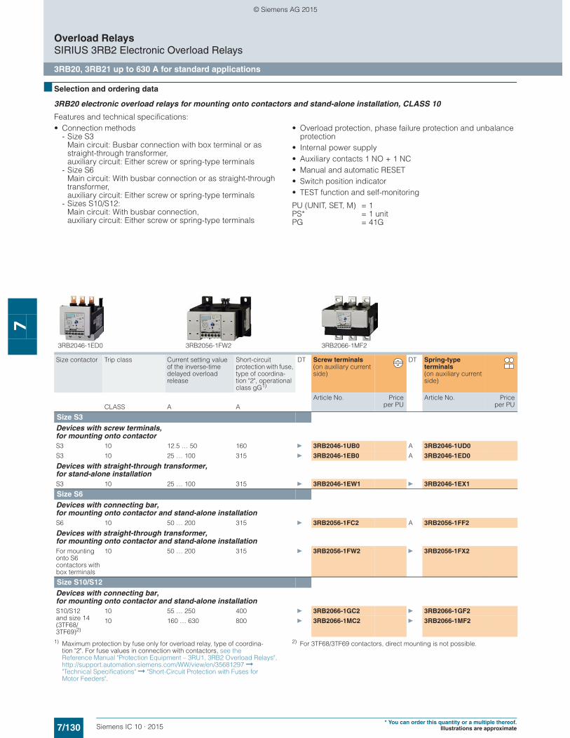
7/130 Siemens IC 10 · 2015* You can order this quantity or a multiple thereof.
Illustrations are approximate
Overload RelaysSIRIUS 3RB2 Electronic Overload Relays
3RB20, 3RB21 up to 630 A for standard applications
7
■ Selection and ordering data
3RB20 electronic overload relays for mounting onto contactors and stand-alone installation, CLASS 10
Features and technical specifications:• Connection methods
- Size S3 Main circuit: Busbar connection with box terminal or as straight-through transformer,auxiliary circuit: Either screw or spring-type terminals
- Size S6Main circuit: With busbar connection or as straight-through transformer,auxiliary circuit: Either screw or spring-type terminals
- Sizes S10/S12: Main circuit: With busbar connection,auxiliary circuit: Either screw or spring-type terminals
• Overload protection, phase failure protection and unbalance protection
• Internal power supply• Auxiliary contacts 1 NO + 1 NC• Manual and automatic RESET• Switch position indicator• TEST function and self-monitoring
PU (UNIT, SET, M) = 1PS* = 1 unitPG = 41G
1) Maximum protection by fuse only for overload relay, type of coordina-tion "2". For fuse values in connection with contactors, see the Reference Manual "Protection Equipment – 3RU1, 3RB2 Overload Relays", http://support.automation.siemens.com/WW/view/en/35681297 ➞ "Technical Specifications" ➞ "Short-Circuit Protection with Fuses for Motor Feeders".
2) For 3TF68/3TF69 contactors, direct mounting is not possible.
Size contactor Trip class Current setting value of the inverse-time delayed overload release
Short-circuit protection with fuse, type of coordina-tion "2", operational class gG1)
DT Screw terminals (on auxiliary current side)
DT Spring-type terminals (on auxiliary current side)
Article No. Priceper PU
Article No. Priceper PUCLASS A A
Size S3Devices with screw terminals, for mounting onto contactorS3 10 12.5 … 50 160 } 3RB2046-1UB0 A 3RB2046-1UD0
S3 10 25 … 100 315 } 3RB2046-1EB0 A 3RB2046-1ED0
Devices with straight-through transformer, for stand-alone installationS3 10 25 … 100 315 } 3RB2046-1EW1 } 3RB2046-1EX1
Size S6Devices with connecting bar, for mounting onto contactor and stand-alone installationS6 10 50 … 200 315 } 3RB2056-1FC2 A 3RB2056-1FF2
Devices with straight-through transformer, for mounting onto contactor and stand-alone installationFor mounting onto S6 contactors with box terminals
10 50 … 200 315 } 3RB2056-1FW2 } 3RB2056-1FX2
Size S10/S12Devices with connecting bar, for mounting onto contactor and stand-alone installationS10/S12 and size 14 (3TF68/3TF69)2)
10 55 … 250 400 } 3RB2066-1GC2 } 3RB2066-1GF2
10 160 … 630 800 } 3RB2066-1MC2 } 3RB2066-1MF2
3RB2046-1ED0 3RB2056-1FW2 3RB2066-1MF2
© Siemens AG 2015
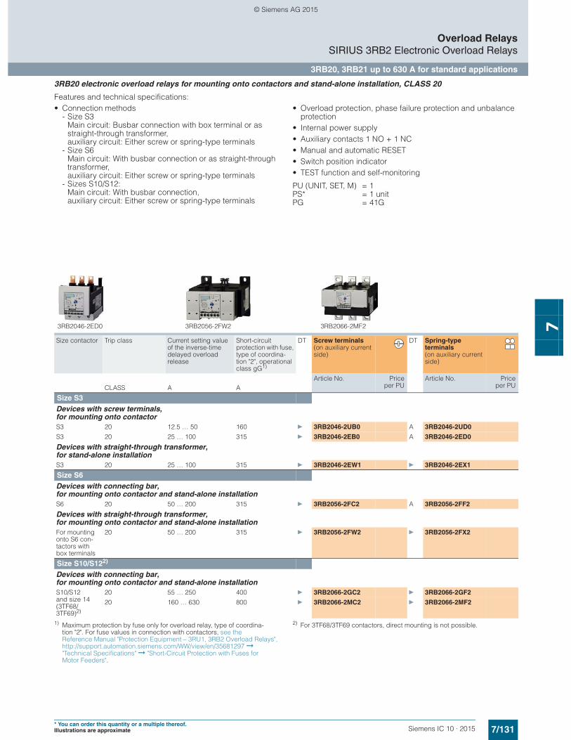
7/131Siemens IC 10 · 2015* You can order this quantity or a multiple thereof.Illustrations are approximate
Overload RelaysSIRIUS 3RB2 Electronic Overload Relays
3RB20, 3RB21 up to 630 A for standard applications
7
3RB20 electronic overload relays for mounting onto contactors and stand-alone installation, CLASS 20
Features and technical specifications:• Connection methods
- Size S3 Main circuit: Busbar connection with box terminal or as straight-through transformer,auxiliary circuit: Either screw or spring-type terminals
- Size S6Main circuit: With busbar connection or as straight-through transformer,auxiliary circuit: Either screw or spring-type terminals
- Sizes S10/S12: Main circuit: With busbar connection,auxiliary circuit: Either screw or spring-type terminals
• Overload protection, phase failure protection and unbalance protection
• Internal power supply• Auxiliary contacts 1 NO + 1 NC• Manual and automatic RESET• Switch position indicator• TEST function and self-monitoring
PU (UNIT, SET, M) = 1PS* = 1 unitPG = 41G
1) Maximum protection by fuse only for overload relay, type of coordina-tion "2". For fuse values in connection with contactors, see the Reference Manual "Protection Equipment – 3RU1, 3RB2 Overload Relays", http://support.automation.siemens.com/WW/view/en/35681297 ➞ "Technical Specifications" ➞ "Short-Circuit Protection with Fuses for Motor Feeders".
2) For 3TF68/3TF69 contactors, direct mounting is not possible.
Size contactor Trip class Current setting value of the inverse-time delayed overload release
Short-circuit protection with fuse, type of coordina-tion "2", operational class gG1)
DT Screw terminals (on auxiliary current side)
DT Spring-type terminals (on auxiliary current side)
Article No. Priceper PU
Article No. Priceper PUCLASS A A
Size S3Devices with screw terminals, for mounting onto contactorS3 20 12.5 … 50 160 } 3RB2046-2UB0 A 3RB2046-2UD0
S3 20 25 … 100 315 } 3RB2046-2EB0 A 3RB2046-2ED0
Devices with straight-through transformer, for stand-alone installationS3 20 25 … 100 315 } 3RB2046-2EW1 } 3RB2046-2EX1
Size S6Devices with connecting bar, for mounting onto contactor and stand-alone installationS6 20 50 … 200 315 } 3RB2056-2FC2 A 3RB2056-2FF2
Devices with straight-through transformer, for mounting onto contactor and stand-alone installationFor mounting onto S6 con-tactors with box terminals
20 50 … 200 315 } 3RB2056-2FW2 } 3RB2056-2FX2
Size S10/S122)
Devices with connecting bar, for mounting onto contactor and stand-alone installationS10/S12 and size 14 (3TF68/3TF69)2)
20 55 … 250 400 } 3RB2066-2GC2 } 3RB2066-2GF2
20 160 … 630 800 } 3RB2066-2MC2 } 3RB2066-2MF2
3RB2046-2ED0 3RB2056-2FW2 3RB2066-2MF2
© Siemens AG 2015
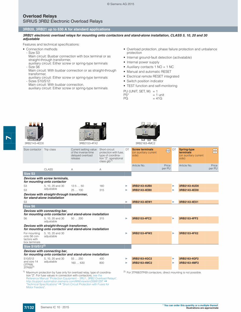
7/132 Siemens IC 10 · 2015* You can order this quantity or a multiple thereof.
Illustrations are approximate
Overload RelaysSIRIUS 3RB2 Electronic Overload Relays
3RB20, 3RB21 up to 630 A for standard applications
7
3RB21 electronic overload relays for mounting onto contactors and stand-alone installation, CLASS 5, 10, 20 and 30 adjustable
Features and technical specifications:• Connection methods
- Size S3 Main circuit: Busbar connection with box terminal or as straight-through transformer,auxiliary circuit: Either screw or spring-type terminals
- Size S6Main circuit: With busbar connection or as straight-through transformer,auxiliary circuit: Either screw or spring-type terminals
- Sizes S10/S12: Main circuit: With busbar connection,auxiliary circuit: Either screw or spring-type terminals
• Overload protection, phase failure protection and unbalance protection
• Internal ground-fault detection (activatable)• Internal power supply• Auxiliary contacts 1 NO + 1 NC• Manual and automatic RESET• Electrical remote RESET integrated• Switch position indicator• TEST function and self-monitoring
PU (UNIT, SET, M) = 1PS* = 1 unitPG = 41G
1) Maximum protection by fuse only for overload relay, type of coordina-tion "2". For fuse values in connection with contactors, see the Reference Manual "Protection Equipment – 3RU1, 3RB2 Overload Relays", http://support.automation.siemens.com/WW/view/en/35681297 ➞ "Technical Specifications" ➞ "Short-Circuit Protection with Fuses for Motor Feeders".
2) For 3TF68/3TF69 contactors, direct mounting is not possible.
Size contactor Trip class Current setting value of the inverse-time delayed overload release
Short-circuit protection with fuse, type of coordina-tion "2", operational class gG1)
DT Screw terminals (on auxiliary current side)
DT Spring-type terminals (on auxiliary current side)
Article No. Priceper PU
Article No. Priceper PUCLASS A A
Size S3Devices with screw terminals, for mounting onto contactorS3 5, 10, 20 and 30
adjustable12.5 … 50 160 } 3RB2143-4UB0 } 3RB2143-4UD0
S3 25 … 100 315 } 3RB2143-4EB0 } 3RB2143-4ED0
Devices with straight-through transformer, for stand-alone installationS3 } 3RB2143-4EW1 } 3RB2143-4EX1
Size S6Devices with connecting bar, for mounting onto contactor and stand-alone installationS6 5, 10, 20 and 30
adjustable50 … 200 315 } 3RB2153-4FC2 } 3RB2153-4FF2
Devices with straight-through transformer, for mounting onto contactor and stand-alone installationFor mounting onto S6 con-tactors with box terminals
5, 10, 20 and 30 adjustable
} 3RB2153-4FW2 } 3RB2153-4FX2
Size S10/S122)
Devices with connecting bar, for mounting onto contactor and stand-alone installationS10/S12 and size 14 (3TF68/3TF69)2)
5, 10, 20 and 30 adjustable
55 … 250 400 } 3RB2163-4GC2 } 3RB2163-4GF2
160 … 630 800 } 3RB2163-4MC2 } 3RB2163-4MF2
3RB2143-4ED0 3RB2153-4FX2 3RB2163-4MC2
© Siemens AG 2015
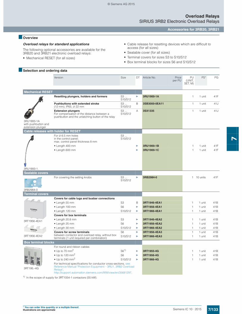
7/133Siemens IC 10 · 2015* You can order this quantity or a multiple thereof.Illustrations are approximate
Overload RelaysSIRIUS 3RB2 Electronic Overload Relays
Accessories for 3RB20, 3RB21
7
■ Overview
Overload relays for standard applications
The following optional accessories are available for the 3RB20 and 3RB21 electronic overload relays:• Mechanical RESET (for all sizes)
• Cable release for resetting devices which are difficult to access (for all sizes)
• Sealable cover (for all sizes)• Terminal covers for sizes S3 to S10/S12• Box terminal blocks for sizes S6 and S10/S12
■ Selection and ordering data
1) In the scope of supply for 3RT1054-1 contactors (55 kW).
Version Size DT Article No. Priceper PU
PU(UNIT,
SET, M)
PS* PG
Mechanical RESET
3RU1900-1A with pushbutton and extension plunger
Resetting plungers, holders and formers S3 ... S10/S12
} 3RU1900-1A 1 1 unit 41F
Pushbuttons with extended stroke (12 mm), IP65, ∅ 22 mm
S3 ... S10/S12
B 3SB3000-0EA11 1 1 unit 41J
Extension plungers For compensation of the distance between a pushbutton and the unlatching button of the relay
S3 ... S10/S12
A 3SX1335 1 1 unit 41J
Cable releases with holder for RESET
3RU1900-1.
For ∅ 6.5 mm holes in the control panel; max. control panel thickness 8 mm
S3 ... S10/S12
• Length 400 mm } 3RU1900-1B 1 1 unit 41F
• Length 600 mm } 3RU1900-1C 1 1 unit 41F
Sealable covers
3RB2984-0
For covering the setting knobs S3 ... S10/S12
} 3RB2984-0 1 10 units 41F
Terminal covers
3RT1956-4EA1
3RT1956-4EA2
Covers for cable lugs and busbar connections
• Length 55 mm S3 B 3RT1946-4EA1 1 1 unit 41B
• Length 100 mm S6 } 3RT1956-4EA1 1 1 unit 41B
• Length 120 mm S10/S12 } 3RT1966-4EA1 1 1 unit 41B
Covers for box terminals
• Length 20.8 mm S3 } 3RT1946-4EA2 1 1 unit 41B
• Length 25 mm S6 } 3RT1956-4EA2 1 1 unit 41B
• Length 30 mm S10/S12 } 3RT1966-4EA2 1 1 unit 41B
Covers for screw terminals between contactor and overload relay, without box terminals (1 unit required per combination)
S6 } 3RT1956-4EA3 1 1 unit 41B
S10/S12 } 3RT1966-4EA3 1 1 unit 41B
Box terminal blocks
3RT195.-4G
For round and ribbon cables
• Up to 70 mm2 S61)} 3RT1955-4G 1 1 unit 41B
• Up to 120 mm2 S6 } 3RT1956-4G 1 1 unit 41B
• Up to 240 mm2 S10/S12 } 3RT1966-4G 1 1 unit 41B
For technical specifications for conductor cross-sections, see Reference Manual "Protection Equipment – 3RU1, 3RB2 Overload Relays", http://support.automation.siemens.com/WW/view/en/35681297.
© Siemens AG 2015

7/134 Siemens IC 10 · 2015* You can order this quantity or a multiple thereof.
Illustrations are approximate
Overload RelaysSIRIUS 3RB2 Electronic Overload Relays
Accessories for 3RB20, 3RB21
7
General accessories
1) PC labeling system for individual inscriptionof unit labeling plates available from:murrplastik Systemtechnik GmbH(see Chapter 16, "Appendix" ➞ "External Partners").
Version Size Color For over-load relays
DT Article No. Priceper PU
PU(UNIT,
SET, M)
PS* PG
Tools for opening spring-type terminals
3RA2908-1A
Spring-type terminals
Screwdrivers For all SIRIUS devices with spring-type terminals
Length approx. 200 mm, 3.0 mm x 0.5 mm
Titanium gray/black, partially insulated
Main and auxiliary circuit connection: 3RB2
A 3RA2908-1A 1 1 unit 41B
Blank labels
3RT1900-1SB20
3RT2900-1SB20
Unit labeling plates1)
for SIRIUS devices20 mm x 7 mm Pastel
turquoise3RB2 D 3RT1900-1SB20 100 340 units 41B
20 mm x 7 mm Titanium gray
3RB2 D 3RT2900-1SB20 100 340 units 41B
Adhesive inscription labels 1)
For SIRIUS devices
19 mm x 6 mm Pastelturquoise
3RB2 C 3RT1900-1SB60 100 3 060 units 41B
19 mm x 6 mm Zinc yellow
3RB2 C 3RT1900-1SD60 100 3 060 units 41BNSB
0_01
429b
IC01
_001
81
© Siemens AG 2015

7/135Siemens IC 10 · 2015
Overload RelaysSIRIUS 3RB2 Electronic Overload Relays
3RB22, 3RB23 up to 630 A for High-Feature applications
7
■ Overview
SIRIUS 3RB22 and 3RB23 evaluation modules
The 3RB22 and 3RB23 electronic overload relays up to 630 A (up to 820 A possible in combination with a series transformer) are from a modular system and comprise an evaluation unit, a current measuring module and a connecting cable.The 3RB22 overload relays (with monostable auxiliary contacts) and the 3RB23 overload relays (with bistable auxiliary contacts) are supplied from an external voltage.
These units have been designed for inverse-time delayed protection of loads with normal and heavy starting("Function", see Reference Manual "Protection Equipment – 3RU1, 3RB2 Overload Relays", http://support.automation.siemens.com/WW/view/en/35681297) against excessive temperature rises due to overload, phase unbalance or phase failure. An overload, phase unbalance or phase failure result in an increase of the motor current beyond the set rated motor current.
This current rise is detected by means of a current measuring module (see page 7/152) and electronically evaluated by the evaluation module which is connected to it. The evaluation electronics sends a signal to the auxiliary contacts. The auxiliary contacts then switch off the load by means of a contactor.
The break time depends on the ratio between the tripping current and current setting Ie and is stored in the form of a long-term stable tripping characteristic (see "Characteristic Curves" http://support.automation.siemens.com/WW/view/en/20357046/134300).
The "tripped" status is signaled by means of a continuous red "OVERLOAD" LED.
The LED indicates imminent tripping of the relay due to overload, phase unbalance or phase failure by flickering when the limit current has been violated. In the case of the 3RB22 and 3RB23 overload relays this warning can also be issued through auxiliary contacts.In addition to the described inverse-time delayed protection of loads against excessive temperature rises, the 3RB22 and 3RB23 electronic overload relays also allow direct temperature monitoring of the motor windings (full motor protection) by connection with broken-wire interlock of a PTC sensor circuit. With this temperature-dependent protection, the loads can be protected against overheating caused indirectly by reduced coolant flow, for example, which cannot be detected by means of the current alone. In the event of overheating, the devices switch off the contactor, and thus the load, by means of the auxiliary contacts. The "tripped" status is signaled by means of a continuously illuminated "THERMISTOR" LED.To protect the loads against high-resistance short circuits due to damage to the insulation, humidity, condensed water, etc., the 3RB22 and 3RB23 electronic overload relays offer the possibi-lity of internal ground-fault detection in conjunction with a func-tion expansion module (for details, see Reference Manual "Protection Equipment - Overload Relays 3RU1, 3RB2",http://support.automation.siemens.com/WW/view/en/35681297, not possible in conjunction with contactor assemblies forwye-delta starting). In the event of a ground fault the 3RB22 and 3RB23 relays trip instantaneously. The "tripped" status is signaled by means of a continuous red "Ground Fault" LED. Signaling through auxiliary contacts is also possible.
After tripping due to overload, phase unbalance, phase failure, thermistor or ground-fault tripping, the relay is reset manually or automatically after the recovery time has elapsed ("Function", see Reference Manual "Protection Equipment – 3RU1, 3RB2 Overload Relays" http://support.automation.siemens.com/WW/view/en/35681297).In conjunction with a function expansion module, the motor current measured by the microprocessor can be output in the form of an analog signal DC 4 mA to 20 mA for operating rotary coil instruments or for feeding into analog inputs of programma-ble logic controllers. With an additional AS-Interface analog module the current values can also be transferred over the AS-i bus system.
The 3RB2 electronic overload relays are suitable for operation with frequency converters. Please follow the instructions in the Reference Manual "Protection Equipment – 3RU1 and 3RB2 Overload Relays", see http://support.automation.siemens.com/WW/view/en/35681297.The devices are manufactured in accordance with environmen-tal guidelines and contain environmentally friendly and reusable materials. They comply with all important worldwide standards and approvals.
Use in hazardous areas
The 3RB22 electronic overload relays (monostable) with the 3RB29 current measuring module are suitable for the overload protection of explosion-proof motors.
EC type test certificate for Category (2) G/D exists. It has the number PTB 05 ATEX 3022.
9
8
7
6
5
4
2
1
2
3
3RB2985 function expansion module:Enables more functions to be added, e.g. internal ground-fault detection and/or an analog output with corresponding signals.
Motor current and trip class setting:Setting the device to the motor current and to the required trip class dependent on the start-up conditions is easy with the two rotary switches.
Connecting terminals (removable joint block):The generously sized terminals permit connection of two conductors with different cross-sections for the auxiliary, control and sensor circuits. Connection is possible with screw connection and alternatively with spring-type connection. Test/RESET button:Enables testing of all important device components and functions,plus resetting of the device after a trip when manual RESET is selected. Selector switch for manual/automatic RESET:With this switch you can choose between manual and automaticRESET.
Red LED "OVERLOAD":A continuous red light signals an active overload trip; a flickering red light signals an imminent trip (overload warning). Red LED "THERMISTOR":A continuous red light signals an active thermistor trip.
Red LED "GND FAULT":A continuous red light signals a ground-fault tripping.
Green LED "READY":A continuous green light signals that the device is working correctly.
1
2
3
9
8
7
6
5
4
NS
B0_
0162
1b
© Siemens AG 2015
7/136 Siemens IC 10 · 2015
Overload RelaysSIRIUS 3RB2 Electronic Overload Relays
3RB22, 3RB23 up to 630 A for High-Feature applications
7
Article No. scheme
Note:
The Article No. scheme is presented here merely for information purposes and for better understanding of the logic behind the article numbers.
For your orders, please use the article numbers quoted in the catalog in the Selection and ordering data.
■ Benefits
The most important features and benefits of the 3RB22 and 3RB23 electronic overload relays are listed in the overview table (see "General Data", page 7/87 onwards).
Advantages through energy efficiency
Overview of the energy management process
We offer you a unique portfolio for industrial energy manage-ment, using an energy management system that helps to opti-mally define your energy needs. We split up our industrial energy management into three phases – identify, evaluate, and realize – and we support you with the appropriate hardware and software solutions in every process phase.
The innovative products of the SIRIUS industrial controls port-folio can also make a substantial contribution to a plant's energy efficiency (see www.siemens.com/sirius/energysaving).
3RB22 and 3RB23 electronic overload relays contribute to energy efficiency throughout the plant as follows:• Reduced inherent power loss • Less heating of the control cabinet • Smaller control cabinet air conditioners can be used
■ Application
Industries
The 3RB22 and 3RB23 electronic overload relays are suitable for customers from all industries who want to guarantee optimum in-verse-time delayed and temperature-dependent protection of their electrical loads (e.g. motors) under normal and heavy start-ing conditions (CLASS 5 to 30), minimize project completion times, inventories and energy consumption, and optimize plant availability and maintenance management.
Application
The 3RB22 and 3RB23 devices have been designed for the protection of three-phase asynchronous and single-phase AC motors.
If single-phase AC motors are to be protected by the 3RB22 and 3RB23 electronic overload relays, the main current paths of the current measuring modules must be series-connected ("Circuit Diagrams", see Reference Manual "Protection Equipment – 3RU1, 3RB2 Overload Relays "http://support.automation.siemens.com/WW/view/en/35681297).
Ambient conditions
The devices are insensitive to external influences such as shocks, corrosive ambient conditions, ageing and temperature fluctuations.
For the temperature range from –25 °C to +60 °C, the 3RB22 and 3RB23 electronic overload relays compensate the temperature in accordance with IEC 60947-4-1.
Configuration notes for use of the devices below –25 °C or above +60 °C on request.
Digit of the Article No. 1st - 3rd 4th 5th 6th 7th 8th 9th 10th 11th
@@@ @ @ @ @ – @ @ @ @
Electronic overload relays 3 R B
SIRIUS 2nd generation 2
Device series @
Size, rated operational current and power @
Version of the automatic RESET, electrical remote RESET @
Trip class (CLASS) @
Setting range of the overload release @
Connection methods @
Installation type @
Example 3 R B 2 2 8 3 – 4 A A 1
IC01
_002
44
© Siemens AG 2015

7/137Siemens IC 10 · 2015
Overload RelaysSIRIUS 3RB2 Electronic Overload Relays
3RB22, 3RB23 up to 630 A for High-Feature applications
7
■ Technical specifications
The following technical information is intended to provide an initial overview of the various types of device and functions.
Detailed information, see • Reference Manual "Protection Equipment – 3RU1, 3RB2
Overload Relays", http://support.automation.siemens.com/WW/view/en/35681297
• or specific information on a particular article number via the product data sheet, http://support.automation.siemens.com/WW/view/en/20357046/133200
Type – Overload relay: evaluation modules 3RB2283-4A.1 3RB2383-4A.1
Size contactor S00 ... S10/S12
Dimensions of evaluation modules (W x H x D)
mm 45 x 111 x 95
General dataTrips in the event of Overload, phase failure and phase unbalance (> 40 % according to NEMA),
+ ground fault (with corresponding function expansion module) and activation of the thermistor motor protection (with closed PTC sensor circuit)
Trip class acc. to IEC 60947-4-1 CLASS 5, 10, 20 and 30 adjustable
Phase failure sensitivity Yes
Overload warning Yes, from 1.125 x Ie for symmetrical loads and from 0.85 x Ie for unsymmetrical loads
Reset and recovery
• Reset options after tripping Manual, automatic and remote RESET
• Recovery time- For automatic RESET min. - for tripping due to overcurrent: 3 (stored permanently)
- for tripping by thermistor: time until the motor temperature has fallen 5 K below the response temperature
- for tripping due to a ground fault: no automatic RESET- For manual RESET min. - for tripping due to overcurrent: 3 (stored permanently)
- for tripping by thermistor: time until the motor temperature has fallen 5 K below the response temperature
- for tripping due to a ground fault: Immediately- For remote RESET min. - for tripping due to overcurrent: 3 (stored permanently)
- for tripping by thermistor: time until the motor temperature has fallen 5 K below the response temperature
- for tripping due to a ground fault: Immediately
Features
• Display of operating state on device Yes, with four LEDs:- green LED "Ready"- red LED "Ground Fault"- red LED "Thermistor"- red LED "Overload"
• TEST function Yes, test of LEDs, electronics, auxiliary contacts and wiring of control circuit by pressing the button TEST/RESET / self-monitoring
• RESET button Yes, with the TEST/RESET button
• STOP button No
Protection and operation of explosion-proof motors
EC type test certificate number according to directive 94/9/EC (ATEX)
PTB 05 ATEX 3022 II (2) GD,see http://support.automation.siemens.com/WW/view/en/23115758
--
Ambient temperatures
• Storage/transport °C -40 ... +80
• Operation °C -25 ... +60
• Temperature compensation °C +60
• Permissible rated current- Temperature inside control cabinet 60 °C % 100- Temperature inside control cabinet 70 °C % On request
Degree of protection acc. to IEC 60529 IP20: Current measuring modules in sizes S6 and S10/S12 with busbar connection in conjunction with cover.
Touch protection acc. to IEC 61140 Finger-safe: Current measuring modules in sizes S6 and S10/S12 with busbar connection in conjunction with cover.
Shock resistance with sine acc. to IEC 60068-2-27 g/ms 15/11
Electromagnetic compatibility (EMC) – Interference immunity
• Conductor-related interference- Burst acc. to IEC 61000-4-4
(corresponds to degree of severity 3)kV 2 (power ports), 1 (signal port)
- Surge acc. to IEC 61000-4-5 (corresponds to degree of severity 3)
kV 2 (line to earth), 1 (line to line)
• Electrostatic discharge according to IEC 61000-4-2 (corresponds to degree of severity 3)
kV 8 (air discharge), 6 (contact discharge)
• Field-related interference according to IEC 61000-4-3 (corresponds to degree of severity 3)
V/m 10
Electromagnetic compatibility (EMC) – emitted interference Degree of severity A according to EN 55011 (CISPR 11) and EN 55022 (CISPR 22)
W
H
D
© Siemens AG 2015
7/138 Siemens IC 10 · 2015
Overload RelaysSIRIUS 3RB2 Electronic Overload Relays
3RB22, 3RB23 up to 630 A for High-Feature applications
7
1) The assignment of auxiliary contacts may be influenced by function expansion modules.
General data (continued)Resistance to extreme climates – air humidity % 100
Dimensions "Dimensional drawings", see • Reference Manual "Protection Equipment – 3RU1, 3RB2 Overload Relays",
http://support.automation.siemens.com/WW/view/en/35681297• Product data sheet,
http://support.automation.siemens.com/WW/view/en/20357046/133200
Installation altitude above sea level m Up to 2 000
Mounting position Any
Type of mounting
• Evaluation modules Stand-alone installation
• Current measuring module Size S00 to S3: Stand-alone installation, S6 and S10/S12: stand-alone installation or mounting onto contactors
Type – Overload relay: evaluation modules 3RB2283-4A.1 3RB2383-4A.1
Size contactor S00 ... S10/S12
Dimensions of evaluation modules (W x H x D)
mm 45 x 111 x 95
W
H
D
Type – Overload relay: evaluation modules 3RB2283-4A.1, 3RB2383-4A.1
Size contactor S00 ... S10/S12
Auxiliary circuitNumber of NO contacts 2
Number of NC contacts 2
Number of CO contacts --
Auxiliary contacts – assignment • Alternative 1- 1 NO for the signal "tripped by overload and/or thermistor"- 1 NC for disconnecting the contactor- 1 NO for the signal "tripped by ground fault" - 1 NC for disconnecting the contactor
or1)
• Alternative 2- 1 NO for the signal "tripped by overload and/or thermistor and/or ground fault" - 1 NC for disconnecting the contactor- 1 NO for overload warning - 1 NC for disconnecting the contactor
Rated insulation voltage Ui (pollution degree 3) V 300
Rated impulse withstand voltage Uimp kV 4
Auxiliary contacts – contact rating
• NC contact with alternating current AC-14/AC-15, rated operational current Ie at Ue- 24 V A 6- 120 V A 6- 125 V A 6- 250 V A 3
• NO contact with alternating current AC-14/AC-15, rated operational current Ie at Ue- 24 V A 6- 120 V A 6- 125 V A 6- 250 V A 3
• NC contact, NO contact with direct current DC-13, rated operational current Ie at Ue- 24 V A 2- 60 V A 0.55- 110 V A 0.3- 125 V A 0.3- 250 V A 0.2
• Conventional thermal current Ith A 5
• Contact reliability (suitability for PLC control; 17 V, 5 mA)
Yes
Short-circuit protection
• With fuse, operational class gG A 6
• With miniature circuit breaker, C characteristic A 1.6
Protective separation between auxiliary current pathsacc. to IEC 60947-1
V 300
CSA, UL, UR rated dataAuxiliary circuit – switching capacity B300, R300
© Siemens AG 2015
7/139Siemens IC 10 · 2015
Overload RelaysSIRIUS 3RB2 Electronic Overload Relays
3RB22, 3RB23 up to 630 A for High-Feature applications
7
1) For the 3RB22 and 3RB23 overload relays in combination with a corresponding function expansion module.
2) Analog input modules, e.g. SM 331, must be configured for 4-wire measuring transducers. In this case the analog input module must not supply current to the analog output of the 3RB22 and 3RB23 relay.
3) If two different conductor cross-sections are connected to one clamping point, both cross-sections must be in the range specified.
Type – Overload relay: evaluation modules 3RB2283-4A.1, 3RB2383-4A.1
Size contactor S00 ... S10/S12
Control circuitRated insulation voltage Ui (pollution degree 3)
V 300
Rated impulse withstand voltage Uimp kV 4
Rated control supply voltage Us
• 50/60 Hz AC V 24 ... 240
• DC V 24 ... 240
Operating range
• 50/60 Hz AC 0.85 × Us min ≤ Us ≤ 1.1 × Us max
• DC 0.85 × Us min ≤ Us ≤ 1.1 × Us max
Rated power
• 50/60 Hz AC W 0.5
• DC W 0.5
Mains buffering time ms 200
Sensor circuitThermistor motor protection (PTC thermistor sensor)
• Summation cold resistance kΩ ≤ 1.5
• Response value kΩ 3.4 ... 3.8
• Return value kΩ 1.5 ... 1.65
Ground-fault detection The information refers to sinusoidal residual currents at 50/60 Hz.
• Tripping value IΔ1)
- For 0.3 × Ie < Imotor < 2.0 × Ie > 0.3 × Ie- For 2.0 × Ie < Imotor < 8.0 × Ie > 0.15 × Imotor
• Response time ttrip ms 500 ... 1 000
Analog output1)2)
Rated values
• Output signal mA 4 ... 20
• Measuring range 0 ... 1.25 × Ie 4 mA corresponds to 0 × Ie 16.8 mA corresponds to 1.0 × Ie 20 mA corresponds to 1.25 × Ie
• Load, max. Ω 100
Conductor cross-sections for the auxiliary, control and sensor circuit as well as the analog outputConnection type Screw terminals
Terminal screw M3, Pozidriv size 2
Operating devices mm 3.0 x 0.5
Prescribed tightening torque Nm 0.8 ... 1.2
Conductor cross-sections (min./max.), 1 or 2 conductors can be connected
• Solid or stranded mm2 1 × (0.5 ... 4)3), 2 × (0.5 ... 2.5)3)
• Finely stranded without end sleeve mm2 --
• Finely stranded with end sleeve (DIN 46228-1) mm2 1 × (0.5 ... 2.5)3), 2 × (0.5 ... 1.5)3)
• AWG cables, solid or stranded AWG 2 × (20 ... 14)
Connection type Spring-type terminals
Operating devices mm 3.0 x 0.5
Conductor cross-sections (min./max.), 1 or 2 conductors can be connected
• Solid or stranded mm2 2 × (0.25 ... 1.5)
• Finely stranded without end sleeve mm2 --
• Finely stranded with end sleeve (DIN 46228-1) mm2 2 × (0.25 ... 1.5)
• AWG cables, solid or stranded AWG 2 × (24 ... 16)
© Siemens AG 2015
7/140 Siemens IC 10 · 2015
Overload RelaysSIRIUS 3RB2 Electronic Overload Relays
3RB22, 3RB23 up to 630 A for High-Feature applications
7
■ Selection and ordering data
Functions of the 3RB22 and 3RB23 evaluation modules in combination with the 3RB2985 function expansion modules
Evaluation modules With function expansion module
Basic functions Inputs
A1/A2 T1/T2 Y1/Y2
3RB2283-4AA1
3RB2283-4AC1
3RB2383-4AA1
3RB2383-4AC1
-- Inverse-time delayed protection, temperature-dependent protection, electrical remote RESET, overload warning
Power supply 24 ... 240 V AC/DC
Connection for PTC sensor
Electrical remote RESET
3RB2985-2CA1 Inverse-time delayed protection, temperature-dependent protection, internal ground-fault detection, electrical remote RESET, overload warning
Power supply 24 ... 240 V AC/DC
Connection for PTC sensor
Electrical remote RESET
3RB2985-2CB1 Inverse-time delayed protection, temperature-dependent protection, internal ground-fault detection, electrical remote RESET, ground-fault signal
Power supply 24 ... 240 V AC/DC
Connection for PTC sensor
Electrical remote RESET
3RB2985-2AA0 Inverse-time delayed protection, temperature-dependent protection, electrical remote RESET, overload warning, analog output
Power supply 24 ... 240 V AC/DC
Connection for PTC sensor
Electrical remote RESET
3RB2985-2AA1 Inverse-time delayed protection, temperature-dependent protection, internal ground-fault detection, electrical remote RESET, overload warning, analog output
Power supply 24 ... 240 V AC/DC
Connection for PTC sensor
Electrical remote RESET
3RB2985-2AB1 Inverse-time delayed protection, temperature-dependent protection, internal ground-fault detection, electrical remote RESET, ground-fault signal, analog output
Power supply 24 ... 240 V AC/DC
Connection for PTC sensor
Electrical remote RESET
Evaluation modules With function expansion module
Outputs
I (–) / I (+) 95/96 NC 97/98 NO 05/06 NC 07/08 NO
3RB2283-4AA1
3RB2283-4AC1
3RB2383-4AA1
3RB2383-4AC1
-- No Disconnection of the contactor (inverse-time delayed/tempe-rature-dependent protection)
Signal "tripped"
Overload warning Overload warning
3RB2985-2CA1 No Disconnection of the contactor (inverse-time delayed/tempe-rature-dependent protection + ground fault)
Signal "tripped"
Overload warning Overload warning
3RB2985-2CB1 No Disconnection of the contactor (inverse-time delayed/tempe-rature-dependent protection)
Signal "tripped"
Disconnection of the contactor (ground fault)
Signal "ground-fault tripping"
3RB2985-2AA0 Analog signal Disconnection of the contactor (inverse-time delayed/tempe-rature-dependent protection)
Signal "tripped"
Overload warning Overload warning
3RB2985-2AA1 Analog signal Disconnection of the contactor (inverse-time delayed/tempe-rature-dependent protection + ground fault)
Signal "tripped"
Overload warning Overload warning
3RB2985-2AB1 Analog signal Disconnection of the contactor (inverse-time delayed/tempe-rature-dependent protection)
Signal "tripped"
Disconnection of the contactor (ground fault)
Signal "ground-fault tripping"
© Siemens AG 2015
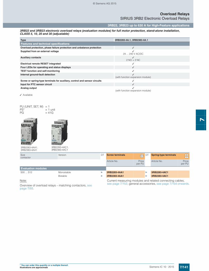
7/141Siemens IC 10 · 2015* You can order this quantity or a multiple thereof.Illustrations are approximate
Overload RelaysSIRIUS 3RB2 Electronic Overload Relays
3RB22, 3RB23 up to 630 A for High-Feature applications
7
3RB22 and 3RB23 electronic overload relays (evaluation modules) for full motor protection, stand-alone installation, CLASS 5, 10, 20 and 30 (adjustable)
✓ Available
PU (UNIT, SET, M) = 1PS* = 1 unitPG = 41G
Note:
Overview of overload relays – matching contactors, see page 7/93.
Current measuring modules and related connecting cables, see page 7/152, general accessories, see page 7/154 onwards.
Type 3RB2283-4A.1, 3RB2383-4A.1
Features and technical specificationsOverload protection, phase failure protection and unbalance protection ✓
Supplied from an external voltage ✓24 ... 240 V AC/DC
Auxiliary contacts ✓2 NO + 2 NC
Electrical remote RESET integrated ✓
Four LEDs for operating and status displays ✓
TEST function and self-monitoring ✓
Internal ground-fault detection ✓(with function expansion module)
Screw or spring-type terminals for auxiliary, control and sensor circuits ✓
Input for PTC sensor circuit ✓
Analog output ✓(with function expansion module)
Size contactor
Version DT Screw terminals DT Spring-type terminals
Article No. Priceper PU
Article No. Priceper PU
Evaluation modulesS00 ... S12 Monostable } 3RB2283-4AA1 } 3RB2283-4AC1
Bistable } 3RB2383-4AA1 } 3RB2383-4AC1
3RB2283-4AA1, 3RB2383-4AA1
3RB2283-4AC1,3RB2383-4AC1
© Siemens AG 2015
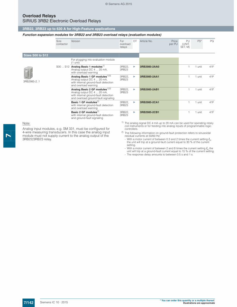
7/142 Siemens IC 10 · 2015* You can order this quantity or a multiple thereof.
Illustrations are approximate
Overload RelaysSIRIUS 3RB2 Electronic Overload Relays
3RB22, 3RB23 up to 630 A for High-Feature applications
7
Function expansion modules for 3RB22 and 3RB23 overload relays (evaluation modules)
Note:
Analog input modules, e.g. SM 331, must be configured for4-wire measuring transducers. In this case the analog input module must not supply current to the analog output of the 3RB22/3RB23 relay.
1) The analog signal DC 4 mA up to 20 mA can be used for operating rotary coil instruments or for feeding into analog inputs of programmable logic controllers.
2) The following information on ground-fault protection refers to sinusoidal residual currents at 50/60 Hz:- With a motor current of between 0.3 and 2 times the current setting Ie,
the unit will trip at a ground-fault current equal to 30 % of the current setting.
- With a motor current of between 2 and 8 times the current setting Ie the unit will trip at a ground-fault current equal to 15 % of the current setting.
- The response delay amounts to between 0.5 s and 1 s.
Size contactor
Version For overload relays
DT Article No. Priceper PU
PU(UNIT,
SET, M)
PS* PG
Sizes S00 to S12 For plugging into evaluation module (1 unit)
3RB2985-2..1
S00 ... S12 Analog Basic 1 modules1)
Analog output DC 4 ... 20 mA, with overload warning
3RB22, 3RB23
} 3RB2985-2AA0 1 1 unit 41F
Analog Basic 1 GF modules1)2)
Analog output DC 4 ... 20 mA, with internal ground-fault detection and overload warning
3RB22, 3RB23
} 3RB2985-2AA1 1 1 unit 41F
Analog Basic 2 GF modules1)2)
Analog output DC 4 ... 20 mA, with internal ground-fault detection and overload ground-fault signaling
3RB22, 3RB23
} 3RB2985-2AB1 1 1 unit 41F
Basic 1 GF modules2) with internal ground-fault detection and overload warning
3RB22, 3RB23
} 3RB2985-2CA1 1 1 unit 41F
Basic 2 GF modules2) with internal ground-fault detection and ground-fault signaling
3RB22, 3RB23
} 3RB2985-2CB1 1 1 unit 41F
© Siemens AG 2015
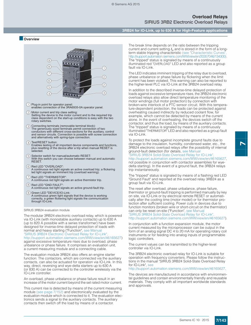
7/143Siemens IC 10 · 2015
Overload RelaysSIRIUS 3RB2 Electronic Overload Relays
3RB24 for IO-Link, up to 630 A for High-Feature applications
7
■ Overview
SIRIUS 3RB24 evaluation module
The modular 3RB24 electronic overload relay, which is powered via IO-Link (with monostable auxiliary contacts) up to 630 A (up to 820 A possible with a series transformer) have been designed for inverse-time delayed protection of loads with normal and heavy starting ("Function", see Manual "SIRIUS 3RB24 Electronic Overload Relay for IO-Link", http://support.automation.siemens.com/WW/view/en/46165627) against excessive temperature rises due to overload, phase unbalance or phase failure. It comprises an evaluation unit, a current measuring module and a connecting cable.
The evaluation module 3RB24 also offers an engine starter function: The contactors, which are connected via the auxiliary contacts, can also be actuated for operation via IO-Link. In this way, direct, reversing and wye-delta starters up to 630 A (or 830 A) can be connected to the controller wirelessly via the IO-Link controller.
An overload, phase unbalance or phase failure result in an increase of the motor current beyond the set rated motor current.
This current rise is detected by means of the current measuring module (see page 7/152) and electronically evaluated by the evaluation module which is connected to it. The evaluation elec-tronics sends a signal to the auxiliary contacts. The auxiliary contacts then switch off the load by means of a contactor.
The break time depends on the ratio between the tripping current and current setting Ie and is stored in the form of a long-term stable tripping characteristic (see "Characteristic Curves", http://support.automation.siemens.com/WW/view/en/20357046/134300) . The "tripped" status is signaled by means of a continuously illuminated red "OVERLOAD" LED and also reported as a group fault via IO-Link.
The LED indicates imminent tripping of the relay due to overload, phase unbalance or phase failure by flickering when the limit current has been violated. This warning can also be reported to the higher-level PLC via IO-Link at the 3RB24 overload relay.
In addition to the described inverse-time delayed protection of loads against excessive temperature rises, the 3RB24 electronic overload relays also allow direct temperature monitoring of the motor windings (full motor protection) by connection with broken-wire interlock of a PTC sensor circuit. With this tempera-ture-dependent protection, the loads can be protected against overheating caused indirectly by reduced coolant flow, for example, which cannot be detected by means of the current alone. In the event of overheating, the devices switch off the contactor, and thus the load, by means of the auxiliary contacts. The "tripped" status is signaled by means of a continuously illuminated "THERMISTOR" LED and also reported as a group fault via IO-Link.
To protect the loads against incomplete ground faults due to damage to the insulation, humidity, condensed water, etc., the 3RB24 electronic overload relays offer the possibility of internal ground-fault detection (for details, see Manual "SIRIUS 3RB24 Solid-State Overload Relay for IO-Link", http://support.automation.siemens.com/WW/view/en/46165627, not possible in conjunction with contactor assemblies for wye-delta starting). In the event of a ground fault, the 3RB24 relays trip instantaneously.
The "tripped" status is signaled by means of a flashing red LED "Ground Fault" and reported at the overload relay 3RB24 as a group fault via IO-Link.
The reset after overload, phase unbalance, phase failure, thermistor or ground-fault tripping is performed manually by key on site, via IO-Link or by electrical remote RESET or automati-cally after the cooling time (motor model) or for thermistor pro-tection after sufficient cooling. Power cuts in devices due to function monitors (broken wire or short-circuit on the thermistor) can only be reset on-site ("Function", see Manual "SIRIUS 3RB24 Solid-State Overload Relay for IO-Link", http://support.automation.siemens.com/WW/view/en/46165627).
In conjunction with a function expansion module, the motor current measured by the microprocessor can be output in the form of an analog signal DC 4 to 20 mA for operating rotary coil instruments or for feeding into analog inputs of programmable logic controllers.
The current values can be transmitted to the higher-level controller via IO-Link.
The 3RB24 electronic overload relay for IO-Link is suitable for operation with frequency converters. Please follow the instruc-tions in the manual "SIRIUS 3RB24 Solid-State Overload Relay for IO-Link", see http://support.automation.siemens.com/WW/view/en/46165627.
The devices are manufactured in accordance with environmen-tal guidelines and contain environmentally friendly and reusable materials. They comply with all important worldwide standards and approvals.
Plug-in point for operator panel: enables connection of the 3RA6935-0A operator panel.
Motor current and trip class setting:Setting the device to the motor current and to the required trip class dependent on the start-up conditions is easy with the two rotary switches.
Connecting terminals (removable terminal block):The generously sized terminals permit connection of two conductors with different cross-sections for the auxiliary, control and sensor circuits. Connection is possible with screw connection and alternatively with spring-type connection.
Test/RESET button:Enables testing of all important device components and functions, plus resetting of the device after a trip when manual RESET is selected.
Selector switch for manual/automatic RESET:With this switch you can choose between manual and automatic RESET.
Red LED "OVERLOAD":A continuous red light signals an active overload trip; a flickering led light signals an imminent trip (overload warning).
Red LED "THERMISTOR":A continuous red light signals an active thermistor trip.
Red LED "GND FAULT":A continuous red light signals an active ground-fault trip.
Green LED "DEVICE/IO-Link:A continuous green light signals that the device is working correctly, a green flickering light signals the communication through IO-Link.
NS
B0_
0218
0b
© Siemens AG 2015
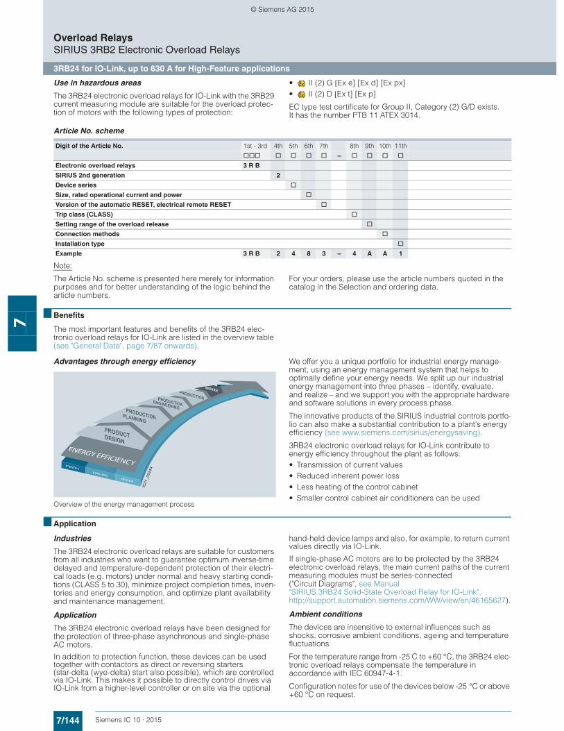
7/144 Siemens IC 10 · 2015
Overload RelaysSIRIUS 3RB2 Electronic Overload Relays
3RB24 for IO-Link, up to 630 A for High-Feature applications
7
Use in hazardous areas
The 3RB24 electronic overload relays for IO-Link with the 3RB29 current measuring module are suitable for the overload protec-tion of motors with the following types of protection:
• II (2) G [Ex e] [Ex d] [Ex px]• II (2) D [Ex t] [Ex p]
EC type test certificate for Group II, Category (2) G/D exists. It has the number PTB 11 ATEX 3014.
Article No. scheme
Note:
The Article No. scheme is presented here merely for information purposes and for better understanding of the logic behind the article numbers.
For your orders, please use the article numbers quoted in the catalog in the Selection and ordering data.
■ Benefits
The most important features and benefits of the 3RB24 elec-tronic overload relays for IO-Link are listed in the overview table (see "General Data", page 7/87 onwards).
Advantages through energy efficiency
Overview of the energy management process
We offer you a unique portfolio for industrial energy manage-ment, using an energy management system that helps to optimally define your energy needs. We split up our industrial energy management into three phases – identify, evaluate, and realize – and we support you with the appropriate hardware and software solutions in every process phase.
The innovative products of the SIRIUS industrial controls portfo-lio can also make a substantial contribution to a plant's energy efficiency (see www.siemens.com/sirius/energysaving).
3RB24 electronic overload relays for IO-Link contribute to energy efficiency throughout the plant as follows:• Transmission of current values • Reduced inherent power loss • Less heating of the control cabinet • Smaller control cabinet air conditioners can be used
■ Application
Industries
The 3RB24 electronic overload relays are suitable for customers from all industries who want to guarantee optimum inverse-time delayed and temperature-dependent protection of their electri-cal loads (e.g. motors) under normal and heavy starting condi-tions (CLASS 5 to 30), minimize project completion times, inven-tories and energy consumption, and optimize plant availability and maintenance management.
Application
The 3RB24 electronic overload relays have been designed for the protection of three-phase asynchronous and single-phase AC motors.
In addition to protection function, these devices can be used together with contactors as direct or reversing starters (star-delta (wye-delta) start also possible), which are controlled via IO-Link. This makes it possible to directly control drives via IO-Link from a higher-level controller or on site via the optional
hand-held device lamps and also, for example, to return current values directly via IO-Link.
If single-phase AC motors are to be protected by the 3RB24 electronic overload relays, the main current paths of the current measuring modules must be series-connected ("Circuit Diagrams", see Manual "SIRIUS 3RB24 Solid-State Overload Relay for IO-Link", http://support.automation.siemens.com/WW/view/en/46165627).
Ambient conditions
The devices are insensitive to external influences such as shocks, corrosive ambient conditions, ageing and temperature fluctuations.
For the temperature range from -25 C to +60 °C, the 3RB24 elec-tronic overload relays compensate the temperature in accordance with IEC 60947-4-1.
Configuration notes for use of the devices below -25 °C or above +60 °C on request.
Digit of the Article No. 1st - 3rd 4th 5th 6th 7th 8th 9th 10th 11th
@@@ @ @ @ @ – @ @ @ @
Electronic overload relays 3 R B
SIRIUS 2nd generation 2
Device series @
Size, rated operational current and power @
Version of the automatic RESET, electrical remote RESET @
Trip class (CLASS) @
Setting range of the overload release @
Connection methods @
Installation type @
Example 3 R B 2 4 8 3 – 4 A A 1
IC01
_002
44
© Siemens AG 2015
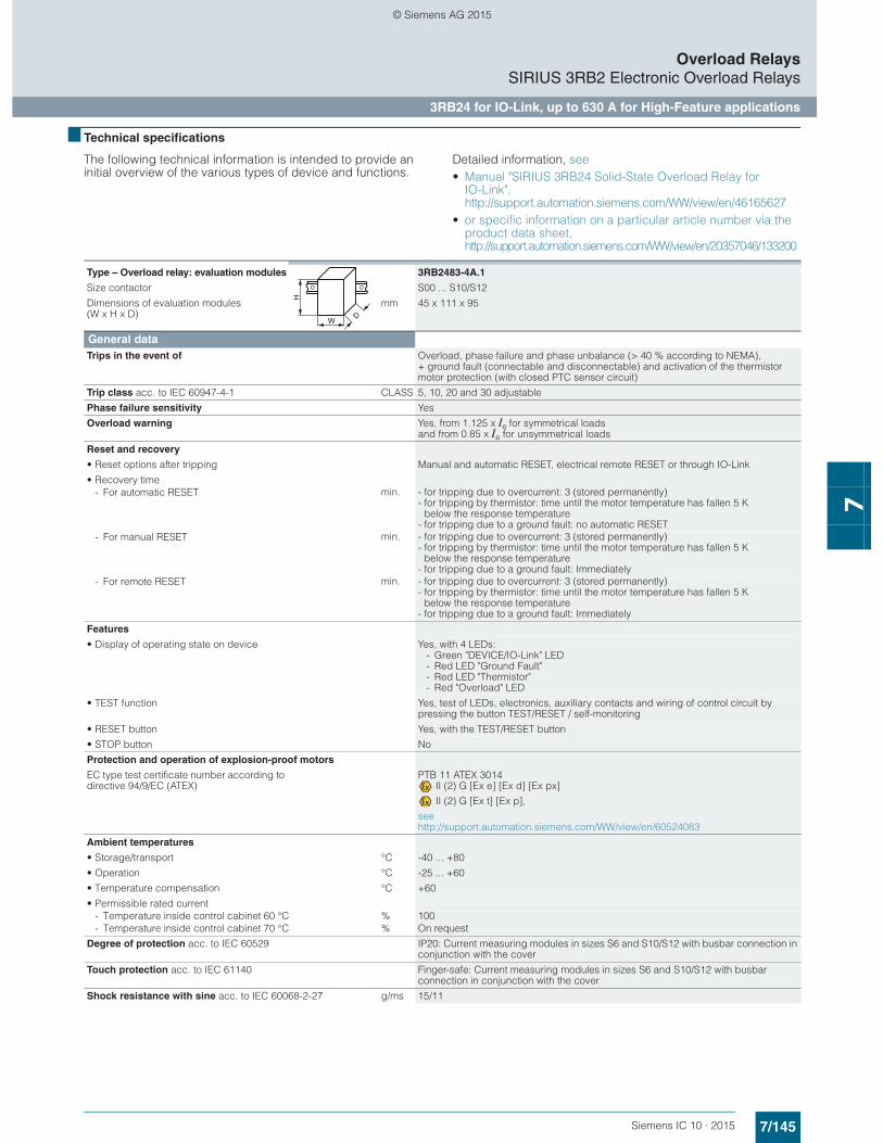
7/145Siemens IC 10 · 2015
Overload RelaysSIRIUS 3RB2 Electronic Overload Relays
3RB24 for IO-Link, up to 630 A for High-Feature applications
7
■ Technical specifications
The following technical information is intended to provide an initial overview of the various types of device and functions.
Detailed information, see • Manual "SIRIUS 3RB24 Solid-State Overload Relay for
IO-Link", http://support.automation.siemens.com/WW/view/en/46165627
• or specific information on a particular article number via the product data sheet, http://support.automation.siemens.com/WW/view/en/20357046/133200
Type – Overload relay: evaluation modules 3RB2483-4A.1
Size contactor S00 ... S10/S12
Dimensions of evaluation modules (W x H x D)
mm 45 x 111 x 95
General dataTrips in the event of Overload, phase failure and phase unbalance (> 40 % according to NEMA),
+ ground fault (connectable and disconnectable) and activation of the thermistor motor protection (with closed PTC sensor circuit)
Trip class acc. to IEC 60947-4-1 CLASS 5, 10, 20 and 30 adjustable
Phase failure sensitivity Yes
Overload warning Yes, from 1.125 x Ie for symmetrical loads and from 0.85 x Ie for unsymmetrical loads
Reset and recovery
• Reset options after tripping Manual and automatic RESET, electrical remote RESET or through IO-Link
• Recovery time- For automatic RESET min. - for tripping due to overcurrent: 3 (stored permanently)
- for tripping by thermistor: time until the motor temperature has fallen 5 K below the response temperature
- for tripping due to a ground fault: no automatic RESET- For manual RESET min. - for tripping due to overcurrent: 3 (stored permanently)
- for tripping by thermistor: time until the motor temperature has fallen 5 K below the response temperature
- for tripping due to a ground fault: Immediately- For remote RESET min. - for tripping due to overcurrent: 3 (stored permanently)
- for tripping by thermistor: time until the motor temperature has fallen 5 K below the response temperature
- for tripping due to a ground fault: Immediately
Features
• Display of operating state on device Yes, with 4 LEDs:- Green "DEVICE/IO-Link" LED- Red LED "Ground Fault"- Red LED "Thermistor"- Red "Overload" LED
• TEST function Yes, test of LEDs, electronics, auxiliary contacts and wiring of control circuit by pressing the button TEST/RESET / self-monitoring
• RESET button Yes, with the TEST/RESET button
• STOP button No
Protection and operation of explosion-proof motors
EC type test certificate number according to directive 94/9/EC (ATEX)
PTB 11 ATEX 3014 II (2) G [Ex e] [Ex d] [Ex px]
II (2) G [Ex t] [Ex p],
see http://support.automation.siemens.com/WW/view/en/60524083
Ambient temperatures
• Storage/transport °C -40 ... +80
• Operation °C -25 ... +60
• Temperature compensation °C +60
• Permissible rated current- Temperature inside control cabinet 60 °C % 100- Temperature inside control cabinet 70 °C % On request
Degree of protection acc. to IEC 60529 IP20: Current measuring modules in sizes S6 and S10/S12 with busbar connection in conjunction with the cover
Touch protection acc. to IEC 61140 Finger-safe: Current measuring modules in sizes S6 and S10/S12 with busbar connection in conjunction with the cover
Shock resistance with sine acc. to IEC 60068-2-27 g/ms 15/11
W
H
D
© Siemens AG 2015
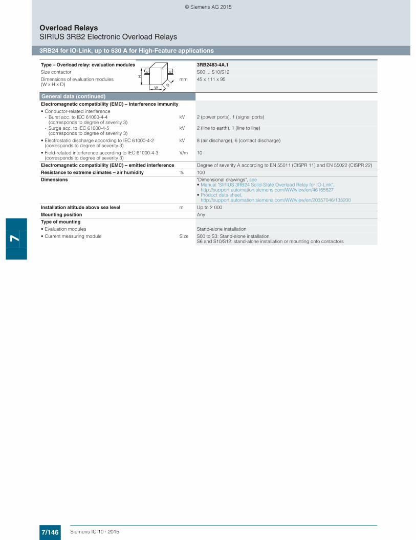
7/146 Siemens IC 10 · 2015
Overload RelaysSIRIUS 3RB2 Electronic Overload Relays
3RB24 for IO-Link, up to 630 A for High-Feature applications
7
General data (continued)Electromagnetic compatibility (EMC) – Interference immunity
• Conductor-related interference- Burst acc. to IEC 61000-4-4
(corresponds to degree of severity 3)kV 2 (power ports), 1 (signal ports)
- Surge acc. to IEC 61000-4-5 (corresponds to degree of severity 3)
kV 2 (line to earth), 1 (line to line)
• Electrostatic discharge according to IEC 61000-4-2 (corresponds to degree of severity 3)
kV 8 (air discharge), 6 (contact discharge)
• Field-related interference according to IEC 61000-4-3 (corresponds to degree of severity 3)
V/m 10
Electromagnetic compatibility (EMC) – emitted interference Degree of severity A according to EN 55011 (CISPR 11) and EN 55022 (CISPR 22)
Resistance to extreme climates – air humidity % 100
Dimensions "Dimensional drawings", see • Manual "SIRIUS 3RB24 Solid-State Overload Relay for IO-Link",
http://support.automation.siemens.com/WW/view/en/46165627• Product data sheet,
http://support.automation.siemens.com/WW/view/en/20357046/133200
Installation altitude above sea level m Up to 2 000
Mounting position Any
Type of mounting
• Evaluation modules Stand-alone installation
• Current measuring module Size S00 to S3: Stand-alone installation, S6 and S10/S12: stand-alone installation or mounting onto contactors
Type – Overload relay: evaluation modules 3RB2483-4A.1
Size contactor S00 ... S10/S12
Dimensions of evaluation modules (W x H x D)
mm 45 x 111 x 95
W
H
D
© Siemens AG 2015
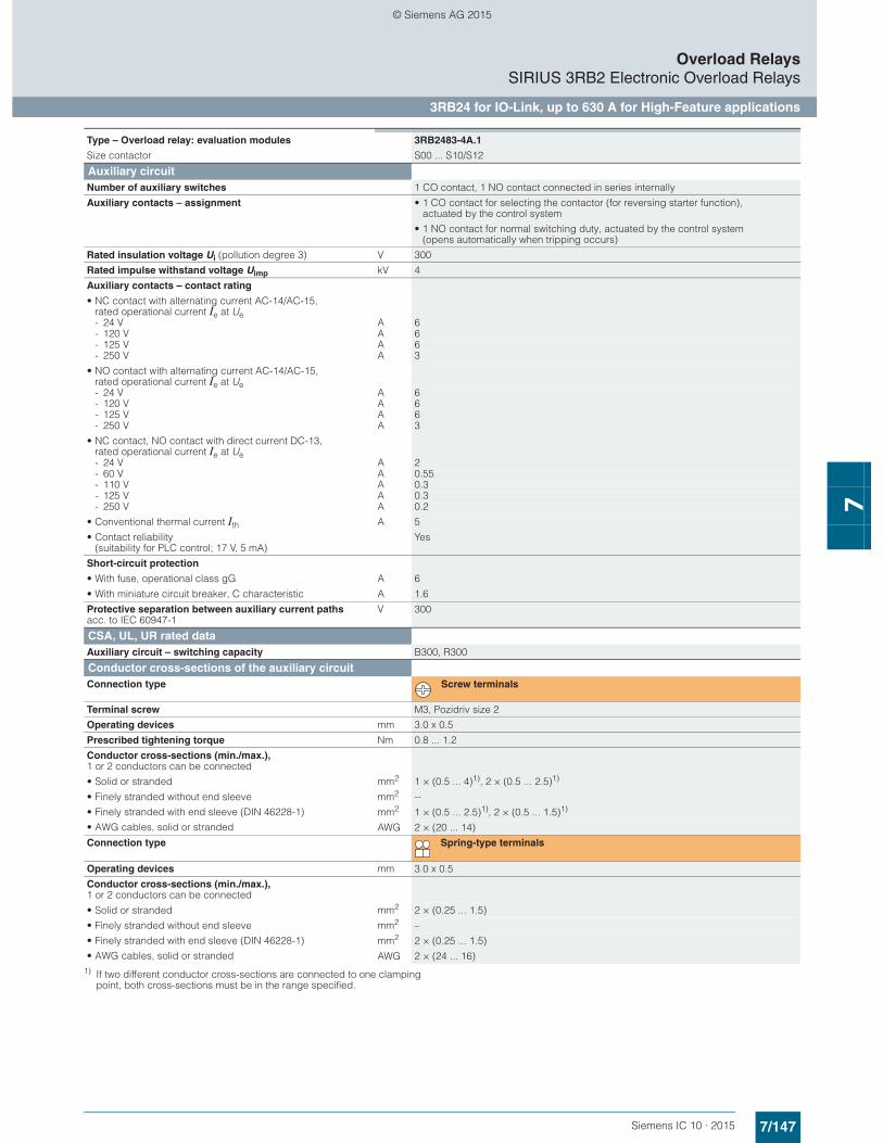
7/147Siemens IC 10 · 2015
Overload RelaysSIRIUS 3RB2 Electronic Overload Relays
3RB24 for IO-Link, up to 630 A for High-Feature applications
7
1) If two different conductor cross-sections are connected to one clamping point, both cross-sections must be in the range specified.
Type – Overload relay: evaluation modules 3RB2483-4A.1
Size contactor S00 ... S10/S12
Auxiliary circuitNumber of auxiliary switches 1 CO contact, 1 NO contact connected in series internally
Auxiliary contacts – assignment • 1 CO contact for selecting the contactor (for reversing starter function), actuated by the control system
• 1 NO contact for normal switching duty, actuated by the control system (opens automatically when tripping occurs)
Rated insulation voltage Ui (pollution degree 3) V 300
Rated impulse withstand voltage Uimp kV 4
Auxiliary contacts – contact rating
• NC contact with alternating current AC-14/AC-15, rated operational current Ie at Ue- 24 V A 6- 120 V A 6- 125 V A 6- 250 V A 3
• NO contact with alternating current AC-14/AC-15, rated operational current Ie at Ue- 24 V A 6- 120 V A 6- 125 V A 6- 250 V A 3
• NC contact, NO contact with direct current DC-13, rated operational current Ie at Ue- 24 V A 2- 60 V A 0.55- 110 V A 0.3- 125 V A 0.3- 250 V A 0.2
• Conventional thermal current Ith A 5
• Contact reliability (suitability for PLC control; 17 V, 5 mA)
Yes
Short-circuit protection
• With fuse, operational class gG A 6
• With miniature circuit breaker, C characteristic A 1.6
Protective separation between auxiliary current paths acc. to IEC 60947-1
V 300
CSA, UL, UR rated dataAuxiliary circuit – switching capacity B300, R300
Conductor cross-sections of the auxiliary circuitConnection type Screw terminals
Terminal screw M3, Pozidriv size 2
Operating devices mm 3.0 x 0.5
Prescribed tightening torque Nm 0.8 ... 1.2
Conductor cross-sections (min./max.), 1 or 2 conductors can be connected
• Solid or stranded mm2 1 × (0.5 ... 4)1), 2 × (0.5 ... 2.5)1)
• Finely stranded without end sleeve
• Finely stranded with end sleeve (DIN 46228-1)
• AWG cables, solid or stranded
mm2 --
mm2 1 × (0.5 ... 2.5)1), 2 × (0.5 ... 1.5)1)
AWG 2 × (20 ... 14)
Connection type Spring-type terminals
Operating devices mm 3.0 x 0.5
Conductor cross-sections (min./max.), 1 or 2 conductors can be connected
• Solid or stranded mm2 2 × (0.25 ... 1.5)
• Finely stranded without end sleeve
• Finely stranded with end sleeve (DIN 46228-1)
• AWG cables, solid or stranded
mm2 –
mm2 2 × (0.25 ... 1.5)
AWG 2 × (24 ... 16)
© Siemens AG 2015
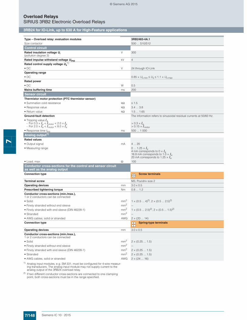
7/148 Siemens IC 10 · 2015
Overload RelaysSIRIUS 3RB2 Electronic Overload Relays
3RB24 for IO-Link, up to 630 A for High-Feature applications
7
1) Analog input modules, e.g. SM 331, must be configured for 4-wire measur-ing transducers. The analog input module may not supply current to the analog output of the 3RB24 overload relay.
2) If two different conductor cross-sections are connected to one clamping point, both cross-sections must be in the range specified.
Type – Overload relay: evaluation modules 3RB2483-4A.1
Size contactor S00 ... S10/S12
Control circuitRated insulation voltage Ui (pollution degree 3)
V 300
Rated impulse withstand voltage Uimp kV 4
Rated control supply voltage Us1)
• DC V 24 through IO-Link
Operating range
• DC 0.85 × Us min ≤ Us ≤ 1.1 × Us max
Rated power
• DC W 0.5
Mains buffering time ms 200
Sensor circuitThermistor motor protection (PTC thermistor sensor)
• Summation cold resistance kΩ ≤ 1.5
• Response value kΩ 3.4 ... 3.8
• Return value kΩ 1.5 ... 1.65
Ground-fault detection The information refers to sinusoidal residual currents at 50/60 Hz.
• Tripping value IΔ- For 0.3 × Ie < Imotor < 2.0 × Ie > 0.3 × Ie- For 2.0 × Ie < Imotor < 8.0 × Ie > 0.15 × Imotor
• Response time ttrip ms 500 ... 1 000
Analog output1)
Rated values
• Output signal mA 4 ... 20
• Measuring range 0 ... 1.25 × Ie 4 mA corresponds to 0 × Ie 16.8 mA corresponds to 1.0 × Ie 20 mA corresponds to 1.25 × Ie
• Load, max. Ω 100
Conductor cross-sections for the control and sensor circuit as well as the analog outputConnection type Screw terminals
Terminal screw M3, Pozidriv size 2
Operating devices mm 3.0 x 0.5
Prescribed tightening torque Nm 0.8 ... 1.2
Conductor cross-sections (min./max.), 1 or 2 conductors can be connected
• Solid mm2 1 × (0.5 ... 4)2), 2 × (0.5 ... 2.5)2)
• Finely stranded without end sleeve mm2 --
• Finely stranded with end sleeve (DIN 46228-1) mm2 1 × (0.5 ... 2.5)2), 2 × (0.5 ... 1.5)2)
• Stranded mm2 --
• AWG cables, solid or stranded AWG 2 × (20 ... 14)
Connection type Spring-type terminals
Operating devices mm 3.0 x 0.5
Conductor cross-sections (min./max.), 1 or 2 conductors can be connected
• Solid mm2 2 × (0.25 ... 1.5)
• Finely stranded without end sleeve mm2 --
• Finely stranded with end sleeve (DIN 46228-1) mm2 2 × (0.25 ... 1.5)
• Stranded mm2 2 × (0.25 ... 1.5)
• AWG cables, solid or stranded AWG 2 × (24 ... 16)
© Siemens AG 2015
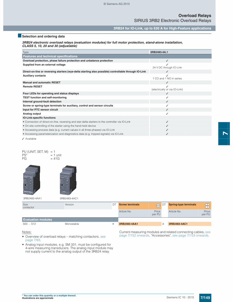
7/149Siemens IC 10 · 2015* You can order this quantity or a multiple thereof.Illustrations are approximate
Overload RelaysSIRIUS 3RB2 Electronic Overload Relays
3RB24 for IO-Link, up to 630 A for High-Feature applications
7
■ Selection and ordering data
3RB24 electronic overload relays (evaluation modules) for full motor protection, stand-alone installation, CLASS 5, 10, 20 and 30 (adjustable)
✓ Available
PU (UNIT, SET, M) = 1PS* = 1 unitPG = 41G
Notes:• Overview of overload relays – matching contactors, see
page 7/93.• Analog input modules, e.g. SM 331, must be configured for
4-wire measuring transducers. The analog input module may not supply current to the analog output of the 3RB24 relay.
Current measuring modules and related connecting cables, see page 7/152 onwards, "Accessories", see page 7/153 onwards.
Type 3RB2483-4A.1
Features and technical specificationsOverload protection, phase failure protection and unbalance protection ✓
Supplied from an external voltage ✓24 V DC through IO-Link
Direct-on-line or reversing starters (wye-delta starting also possible) controllable through IO-Link ✓
Auxiliary contacts ✓1 CO and 1 NO in series
Manual and automatic RESET ✓
Remote RESET ✓(electrically or via IO-Link)
Four LEDs for operating and status displays ✓
TEST function and self-monitoring ✓
Internal ground-fault detection ✓
Screw or spring-type terminals for auxiliary, control and sensor circuits ✓
Input for PTC sensor circuit ✓
Analog output ✓
IO-Link-specific functions
• Connection of direct-on-line, reversing and star-delta starters to the controller via IO-Link ✓
• On-site controlling of the starter using the hand-held device ✓
• Accessing process data (e.g. current values in all three phases) via IO-Link ✓
• Accessing parameterization and diagnostics data (e.g. tripped signals) via IO-Link ✓
Size contactor
Version DT Screw terminals DT Spring-type terminals
Article No. Priceper PU
Article No. Priceper PU
Evaluation modules S00 ... S12 Monostable } 3RB2483-4AA1 A 3RB2483-4AC1
3RB2483-4AC13RB2483-4AA1
© Siemens AG 2015

7/150 Siemens IC 10 · 2015
Overload RelaysSIRIUS 3RB2 Electronic Overload Relays
Current measuring modules for 3RB22, 3RB23, 3RB24
7
■ Overview
SIRIUS 3RB2906 current measuring module
The current measuring modules are designed as system com-ponents for connecting to evaluation units 3RB22 to 3RB24. Using these evaluation units the motor current is measured and the measured value sent to the evaluation unit for evaluation.
The current measuring modules in sizes up to S3 are equipped with straight-through transformers and can be snap-fitted under the evaluation units. The larger evaluation units are installed directly on the contactor or as stand-alone units.
■ Technical specifications
The following technical information is intended to provide an initial overview of the various types of device and functions.
Detailed information, see Reference Manual "Protection Equipment - Overload Relays 3RU1, 3RB2", http://support.automation.siemens.com/WW/view/en/35681297
Type – Overload relays: Current measuring modules
3RB2906 3RB2956 3RB2966
Size contactor S00/S0 S2/S3 S6 S10/S12
Dimensions of current measuring modules (W x H x D)
mm 45 x 84 x 45 55 x 94 x 72 120 x 119 x 145 145 x 147 x 148
Main circuitRated insulation voltage Ui (pollution degree 3)
V 1 000
Rated impulse withstand voltage Uimp kV 6 8
Rated operational voltage Ue V 1 000
Type of current
• Direct current No
• Alternating current Yes, 50/60 Hz ± 5 %
Current setting A 0.3 ... 3; 2.4 ... 25
10 ... 100 20 ... 200 63 ... 630
Power loss per unit (max.) W 0.5
Short-circuit protection
• With fuse without contactor See "Selection and ordering data" on page 7/152
• With fuse and contactor See configuration manuals
• "Configuring SIRIUS Innovations – Selection Data for Fuseless and Fused Load Feeders", http://support.automation.siemens.com/WW/view/en/50250039
• "SIRIUS Configuration – Selection Data for Fuseless Load Feeders", http://support.automation.siemens.com/WW/view/en/68115041
Protective separation between main and auxiliary current paths acc. to IEC 60947-1 (pollution degree 2)
• For systems with grounded neutral point V 690
• For systems with ungrounded neutral point V 600
W
H
D
© Siemens AG 2015
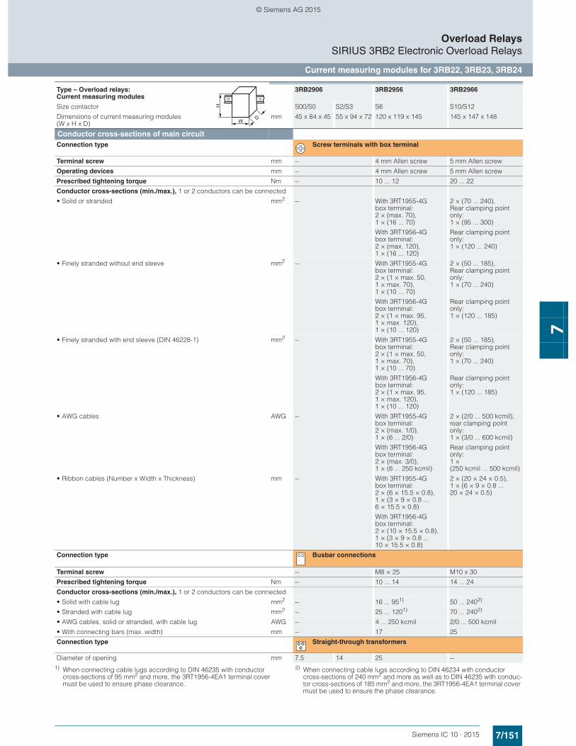
7/151Siemens IC 10 · 2015
Overload RelaysSIRIUS 3RB2 Electronic Overload Relays
Current measuring modules for 3RB22, 3RB23, 3RB24
7
1) When connecting cable lugs according to DIN 46235 with conductor cross-sections of 95 mm2 and more, the 3RT1956-4EA1 terminal cover must be used to ensure phase clearance.
2) When connecting cable lugs according to DIN 46234 with conductor cross-sections of 240 mm2 and more as well as to DIN 46235 with conduc-tor cross-sections of 185 mm2 and more, the 3RT1956-4EA1 terminal cover must be used to ensure the phase clearance.
Conductor cross-sections of main circuitConnection type Screw terminals with box terminal
Terminal screw mm -- 4 mm Allen screw 5 mm Allen screw
Operating devices mm -- 4 mm Allen screw 5 mm Allen screw
Prescribed tightening torque Nm -- 10 ... 12 20 ... 22
Conductor cross-sections (min./max.), 1 or 2 conductors can be connected
• Solid or stranded mm2 -- With 3RT1955-4G box terminal: 2 × (max. 70), 1 × (16 ... 70)
With 3RT1956-4G box terminal: 2 × (max. 120), 1 × (16 ... 120)
2 × (70 ... 240), Rear clamping point only: 1 × (95 ... 300)
Rear clamping point only: 1 × (120 ... 240)
• Finely stranded without end sleeve mm2 -- With 3RT1955-4G box terminal: 2 × (1 × max. 50, 1 × max. 70), 1 × (10 ... 70)
With 3RT1956-4G box terminal: 2 × (1 × max. 95, 1 × max. 120), 1 × (10 ... 120)
2 × (50 ... 185), Rear clamping point only: 1 × (70 ... 240)
Rear clamping point only: 1 × (120 ... 185)
• Finely stranded with end sleeve (DIN 46228-1) mm2 -- With 3RT1955-4G box terminal: 2 × (1 × max. 50, 1 × max. 70), 1 × (10 ... 70)
With 3RT1956-4G box terminal: 2 × (1 × max. 95, 1 × max. 120), 1 × (10 ... 120)
2 × (50 ... 185), Rear clamping point only: 1 × (70 ... 240)
Rear clamping point only: 1 × (120 ... 185)
• AWG cables AWG -- With 3RT1955-4G box terminal: 2 × (max. 1/0), 1 × (6 ... 2/0)
With 3RT1956-4G box terminal: 2 × (max. 3/0), 1 × (6 ... 250 kcmil)
2 × (2/0 ... 500 kcmil), rear clamping point only: 1 × (3/0 ... 600 kcmil)
Rear clamping point only: 1 × (250 kcmil ... 500 kcmil)
• Ribbon cables (Number x Width x Thickness) mm -- With 3RT1955-4G box terminal: 2 × (6 × 15.5 × 0.8), 1 × (3 × 9 × 0.8 ... 6 × 15.5 × 0.8)
With 3RT1956-4G box terminal: 2 × (10 × 15.5 × 0.8), 1 × (3 × 9 × 0.8 ... 10 × 15.5 × 0.8)
2 × (20 × 24 × 0.5), 1 × (6 × 9 × 0.8 ... 20 × 24 × 0.5)
Connection type Busbar connections
Terminal screw -- M8 × 25 M10 x 30
Prescribed tightening torque Nm -- 10 ... 14 14 ... 24
Conductor cross-sections (min./max.), 1 or 2 conductors can be connected
• Solid with cable lug mm2 -- 16 ... 951) 50 ... 2402)
• Stranded with cable lug mm2 -- 25 ... 1201) 70 ... 2402)
• AWG cables, solid or stranded, with cable lug AWG -- 4 ... 250 kcmil 2/0 ... 500 kcmil
• With connecting bars (max. width) mm -- 17 25
Connection type Straight-through transformers
Diameter of opening mm 7.5 14 25 --
Type – Overload relays: Current measuring modules
3RB2906 3RB2956 3RB2966
Size contactor S00/S0 S2/S3 S6 S10/S12
Dimensions of current measuring modules (W x H x D)
mm 45 x 84 x 45 55 x 94 x 72 120 x 119 x 145 145 x 147 x 148W
H
D
© Siemens AG 2015

7/152 Siemens IC 10 · 2015* You can order this quantity or a multiple thereof.
Illustrations are approximate
Overload RelaysSIRIUS 3RB2 Electronic Overload Relays
Current measuring modules for 3RB22, 3RB23, 3RB24
7
■ Selection and ordering data
Current measuring modules (essential accessory)
Note:
The connecting cable between the current measuring module and the evaluation module is not included in the scope of supply; please order separately (see "Accessories").
1) Maximum protection by fuse only for overload relay, type of coordination "2". For fuse values in connection with contactors, see Configuration Manuals- "Configuring SIRIUS Innovations – Selection Data for Fuseless and
Fused Load Feeders", http://support.automation.siemens.com/WW/view/en/39714188
- "SIRIUS Configuration – Selection Data for Fuseless Load Feeders", http://support.automation.siemens.com/WW/view/en/40625241.
2) For 3TF68/3TF69 contactors, direct mounting is not possible.
■ Accessories
Additional general accessories, see page 7/154.
Size contactor
Current setting value of the inverse-time delayed overload release
Short-circuit protec-tion with fuse, type of coordination "2", operational class gG1)
For overload relays
DT Article No. Priceper PU
PU(UNIT,
SET, M)
PS* PG
A A
Sizes S00/S0Devices with straight-through transformer, for stand-alone installation S00/S0 0.3 … 3 20 3RB22 to
3RB24} 3RB2906-2BG1 1 1 unit 41G
2.4 … 25 63 } 3RB2906-2DG1 1 1 unit 41G
Sizes S2/S3Devices with straight-through transformer, for stand-alone installation S2/S3 10 … 100 315 3RB22 to
3RB24} 3RB2906-2JG1 1 1 unit 41G
Size S6Devices with busbar connection, for mounting onto contactor and stand-alone installation S6 20 … 200 315 3RB22 to
3RB24} 3RB2956-2TH2 1 1 unit 41G
Devices with straight-through transformer, for mounting onto contactor and stand-alone installation For mounting onto S6 con-tactors with box terminals
20 … 200 315 3RB22 to 3RB24
} 3RB2956-2TG2 1 1 unit 41G
Sizes S10/S122)
Devices with busbar connection, for mounting onto contactor and stand-alone installation S10/S12 and size 14 (3TF68/3TF69)2)
63 … 630 800 3RB22 to 3RB24
} 3RB2966-2WH2 1 1 unit 41G
3RB2906-2JG13RB2906-2BG1, 3RB2906-2DG1
3RB2956-2TG2 3RB2966-2WH2
Size contactor
Version For overload relays
DT Article No. Priceper PU
PU(UNIT,
SET, M)
PS* PG
Connecting cables (necessary accessories)
3RB2987-2.
For connection between evaluation module and current measuring module
S00 ... S3 • Length 0.1 m (only for mounting of the evaluation module directly onto the current measuring module)
3RB24, 3RB29
} 3RB2987-2B 1 1 unit 41F
S00 ... S12 • Length 0.5 m 3RB24, 3RB29
} 3RB2987-2D 1 1 unit 41F
© Siemens AG 2015

7/153Siemens IC 10 · 2015* You can order this quantity or a multiple thereof.Illustrations are approximate
Overload RelaysSIRIUS 3RB2 Electronic Overload Relays
Accessories for 3RB22, 3RB23, 3RB24
7
■ Overview
Overload relays for High-Feature applications
The following optional accessories are available for the 3RB22 to 3RB24 electronic overload relays:• Operator panel for the evaluation modules 3RB24• Manuals, see "More information"• Sealable cover for the evaluation modules 3RB22 to 3RB24
• Terminal covers for the 3RB29 current measuring modules size S6 and S10/S12
• Box terminal blocks for the 3RB29 current measuring modules size S6 and S10/S12
• Push-in lugs for screw fixing for 3RB22 to 3RB24 evaluation modules and 3RB2906 current measuring modules
■ Selection and ordering data
Accessories for 3RB24 overload relays
Additional general accessories, see next page.
■ More information
Manuals • System Manual "SIRIUS Innovations – System Overview"
http://support.automation.siemens.com/WW/view/en/60311318• Manual "SIRIUS 3RB24 Solid-State Overload Relay for IO-Link"
http://support.automation.siemens.com/WW/view/en/46165627
Version For overload relays
DT Article No. Priceper PU
PU(UNIT,
SET, M)
PS* PG
Operator panels for evaluation modules
3RA6935-0A
Operator panels (set)
One set comprises:• 1 x operator panel• 1 x 3RA6936-0A enabling module• 1 x 3RA6936-0B interface cover• 1 x fixing terminal
Note:
The connecting cable between the evaluation module and the operator panel is not included in the scope of supply; please order separately.
3RB24 A 3RA6935-0A 1 1 unit 42F
Connecting cable Length 2.5 m (round), for connecting the evaluation module to the operator panel
3RB24 } 3UF7933-0BA00-0 1 1 unit 42J
Enabling modules (replacement) 3RB24 A 3RA6936-0A 1 1 unit 42F
Interface covers 3RB24 A 3RA6936-0B 1 5 units 42F
© Siemens AG 2015
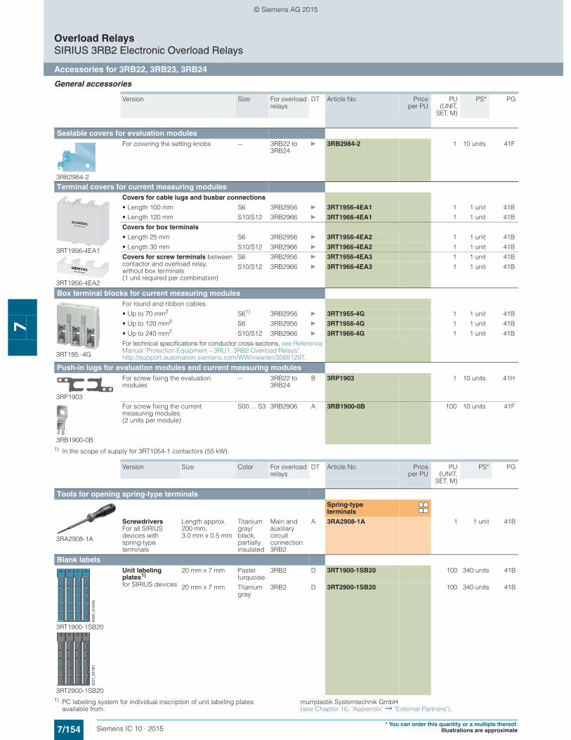
7/154 Siemens IC 10 · 2015* You can order this quantity or a multiple thereof.
Illustrations are approximate
Overload RelaysSIRIUS 3RB2 Electronic Overload Relays
Accessories for 3RB22, 3RB23, 3RB24
7
General accessories
1) In the scope of supply for 3RT1054-1 contactors (55 kW).
1) PC labeling system for individual inscription of unit labeling plates available from:
murrplastik Systemtechnik GmbH(see Chapter 16, "Appendix" ➞ "External Partners").
Version Size For overload relays
DT Article No. Priceper PU
PU(UNIT,
SET, M)
PS* PG
Sealable covers for evaluation modules
3RB2984-2
For covering the setting knobs -- 3RB22 to 3RB24
} 3RB2984-2 1 10 units 41F
Terminal covers for current measuring modules
3RT1956-4EA1
3RT1956-4EA2
Covers for cable lugs and busbar connections
• Length 100 mm S6 3RB2956 } 3RT1956-4EA1 1 1 unit 41B
• Length 120 mm S10/S12 3RB2966 } 3RT1966-4EA1 1 1 unit 41B
Covers for box terminals
• Length 25 mm S6 3RB2956 } 3RT1956-4EA2 1 1 unit 41B
• Length 30 mm S10/S12 3RB2966 } 3RT1966-4EA2 1 1 unit 41B
Covers for screw terminals between contactor and overload relay, without box terminals (1 unit required per combination)
S6 3RB2956 } 3RT1956-4EA3 1 1 unit 41B
S10/S12 3RB2966 } 3RT1966-4EA3 1 1 unit 41B
Box terminal blocks for current measuring modules
3RT195.-4G
For round and ribbon cables
• Up to 70 mm2 S61) 3RB2956 } 3RT1955-4G 1 1 unit 41B
• Up to 120 mm2 S6 3RB2956 } 3RT1956-4G 1 1 unit 41B
• Up to 240 mm2 S10/S12 3RB2966 } 3RT1966-4G 1 1 unit 41B
For technical specifications for conductor cross-sections, see Reference Manual "Protection Equipment – 3RU1, 3RB2 Overload Relays", http://support.automation.siemens.com/WW/view/en/35681297.
Push-in lugs for evaluation modules and current measuring modules
3RP1903
For screw fixing the evaluation modules
-- 3RB22 to 3RB24
B 3RP1903 1 10 units 41H
3RB1900-0B
For screw fixing the current measuring modules(2 units per module)
S00 ... S3 3RB2906 A 3RB1900-0B 100 10 units 41F
Version Size Color For overload relays
DT Article No. Priceper PU
PU(UNIT,
SET, M)
PS* PG
Tools for opening spring-type terminals
3RA2908-1A
Spring-type terminals
Screwdrivers For all SIRIUS devices with spring-type terminals
Length approx. 200 mm, 3.0 mm x 0.5 mm
Titanium gray/black, partially insulated
Main and auxiliary circuit connection: 3RB2
A 3RA2908-1A 1 1 unit 41B
Blank labels
3RT1900-1SB20
3RT2900-1SB20
Unit labeling plates1)
for SIRIUS devices
20 mm x 7 mm Pastel turquoise
3RB2 D 3RT1900-1SB20 100 340 units 41B
20 mm x 7 mm Titanium gray
3RB2 D 3RT2900-1SB20 100 340 units 41B
NSB
0_01
429b
IC01
_001
81
© Siemens AG 2015