low voltage equipment bt lv tip shortform catalogue - siemens
TRANSCRIPT
1
Answers for construction.
Low Voltage Equipment
BT LV TIP Shortform Catalogue
Catalogue - 2011
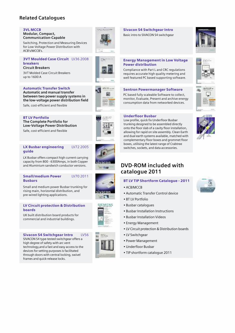
Related Catalogues
DVD-ROM included withcatalogue 2011
3VL MCCBModular, Compact,Communication-Capable
Switching, Protection and Measuring Devicesfor Low-Voltage Power Distribution with ACB's/MCCB's.
3VT Moulded Case Circuit LV36 2008breakersCircuit Breakers
3VT Molded Case Circuit Breakers up to 1600 A
Automatic Transfer SwitchAutomatic and manual transferbetween two power supply systems inthe low-voltage power distribution field
Safe, cost-efficient and flexible
Sivacon S4 Switchgear IntroBasic intro to SIVACON S4 switchgear
Energy Management in Low VoltagePower distributionCompliance with Part L and CRC regulationsrequires accurate high quality metering andwell featured PC based supporting software.
Sentron Powermanager SoftwarePC based fully scaleable Software to collect,monitor, Evaluate, Present and archive energyconsumption data from networked devices.
BT LV TIP Shortform Catalogue - 2011
• ACB/MCCB
• Automatic Transfer Control device
• BT LV Portfolio
• Busbar catalogues
• Busbar Installation Instructions
• Busbar Installation Videos
• Energy Management
• LV Circuit protection & Distribution boards
• LV Switchgear
• Power Management
• Underfloor Busbar
• TIP shortform catalogue 2011
BT LV PortfolioThe Complete Portfolio for Low-Voltage Power Distribution
Safe, cost-efficient and flexible
LX Busbar engineering LV72 2005guide
LX Busbar offers compact high current carryingcapacity from 800 - 6300Amps, in both Copperand Aluminium sandwich conductor versions.
Small/medium Power LV70 2011Busbars
Small and medium power Busbar trunking forrising main, horizontal distribution, andpre-wired lighting applications.
LV Circuit protection & DistributionboardsUK built distribution board products forcommercial and industrial buildings.
Sivacon S4 Switchgear Intro LV56SIVACON S4 type-tested switchgear offers ahigh degree of safety with arc venttechnology,and a fast and easy access to thedevices for setting purposes is facilitatedthrough doors with central locking, swivelframes and quick-release locks.
Underfloor BusbarLow profile, quick fix Underfloor Busbartrunking designed to be assembled directlyonto the floor slab of a cavity floor installation,allowing for rapid on site assembly. Clean Earthand dual earth systems available, matched withcomplementary floor boxes and grommet floorboxes, utilising the latest range of Crabtreeswitches, sockets, and data accessories.
Automatic Transfer Control Device 11
S4 Switchgear 10
Power Managementdevices/software
9
ACB’s/MCCB Circuit Breakers 8
Distribution Boards andCircuit Protection
7
Underfloor Busbar 6
LR Cast Resin IP68 Busbar 5
LX Busbar System 4
BD2 Busbar System 3
BD01 Busbar System 2
CD-K System 25A-40A
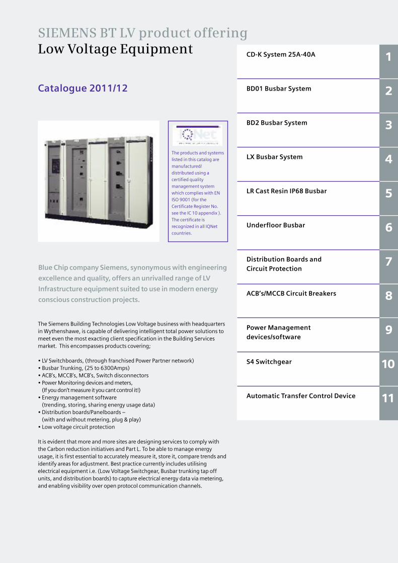
SIEMENS BT LV product offering Low Voltage Equipment
The products and systems
listed in this catalog are
manufactured/
distributed using a
certified quality
management system
which complies with EN
ISO 9001 (for the
Certificate Register No.
see the IC 10 appendix ).
The certificate is
recognized in all IQNet
countries.
Catalogue 2011/12
1
Blue Chip company Siemens, synonymous with engineering
excellence and quality, offers an unrivalled range of LV
Infrastructure equipment suited to use in modern energy
conscious construction projects.
The Siemens Building Technologies Low Voltage business with headquartersin Wythenshawe, is capable of delivering intelligent total power solutions tomeet even the most exacting client specification in the Building Servicesmarket. This encompasses products covering;
• LV Switchboards, (through franchised Power Partner network) • Busbar Trunking, (25 to 6300Amps)• ACB’s, MCCB’s, MCB’s, Switch disconnectors• Power Monitoring devices and meters, (If you don’t measure it you cant control it!)
• Energy management software (trending, storing, sharing energy usage data)
• Distribution boards/Panelboards – (with and without metering, plug & play)
• Low voltage circuit protection
It is evident that more and more sites are designing services to comply withthe Carbon reduction initiatives and Part L. To be able to manage energyusage, it is first essential to accurately measure it, store it, compare trends andidentify areas for adjustment. Best practice currently includes utilisingelectrical equipment i.e. (Low Voltage Switchgear, Busbar trunking tap offunits, and distribution boards) to capture electrical energy data via metering,and enabling visibility over open protocol communication channels.
1.1
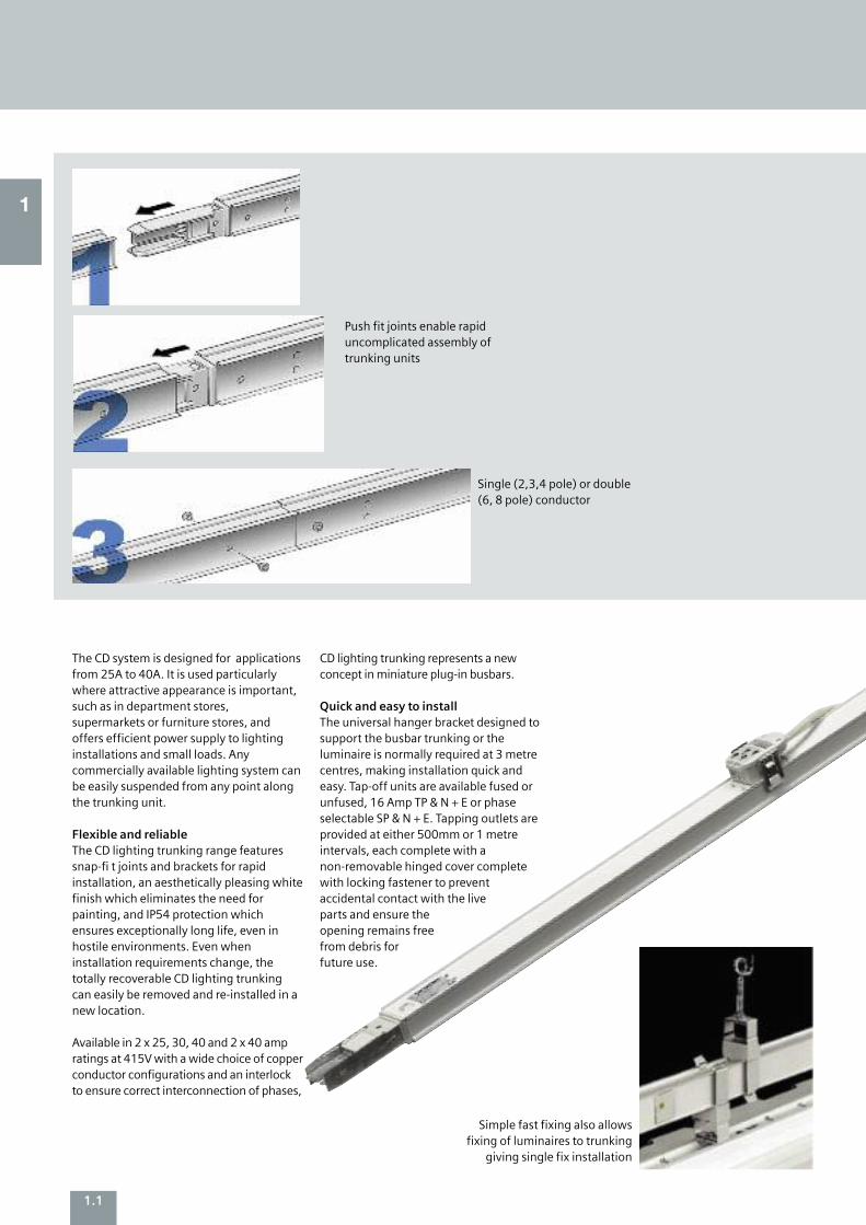
The CD system is designed for applicationsfrom 25A to 40A. It is used particularlywhere attractive appearance is important,such as in department stores,supermarkets or furniture stores, andoffers efficient power supply to lightinginstallations and small loads. Anycommercially available lighting system canbe easily suspended from any point alongthe trunking unit.
Flexible and reliableThe CD lighting trunking range featuressnap-fi t joints and brackets for rapidinstallation, an aesthetically pleasing whitefinish which eliminates the need forpainting, and IP54 protection whichensures exceptionally long life, even inhostile environments. Even wheninstallation requirements change, thetotally recoverable CD lighting trunkingcan easily be removed and re-installed in anew location.
Available in 2 x 25, 30, 40 and 2 x 40 ampratings at 415V with a wide choice of copperconductor configurations and an interlockto ensure correct interconnection of phases,
CD lighting trunking represents a newconcept in miniature plug-in busbars.
Quick and easy to install The universal hanger bracket designed tosupport the busbar trunking or theluminaire is normally required at 3 metrecentres, making installation quick andeasy. Tap-off units are available fused orunfused, 16 Amp TP & N + E or phaseselectable SP & N + E. Tapping outlets areprovided at either 500mm or 1 metreintervals, each complete with anon-removable hinged cover completewith locking fastener to prevent accidental contact with the live parts and ensure the opening remains free from debris for future use.
Push fit joints enable rapiduncomplicated assembly oftrunking units
Simple fast fixing also allowsfixing of luminaires to trunking
giving single fix installation
Single (2,3,4 pole) or double (6, 8 pole) conductor
1
1.2
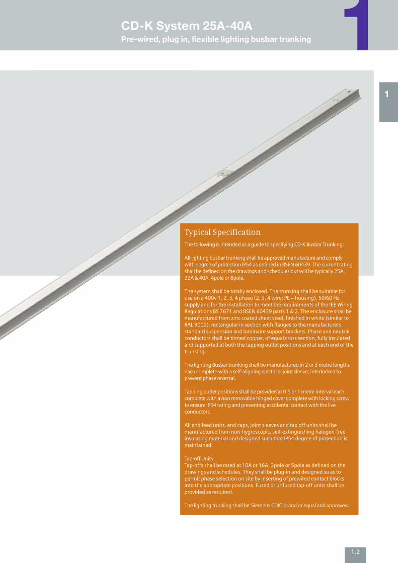
The following is intended as a guide to specifying CD-K Busbar Trunking:
All lighting busbar trunking shall be approved manufacture and complywith degree of protection IP54 as defined in BSEN 60439. The current ratingshall be defined on the drawings and schedules but will be typically 25A,32A & 40A, 4pole or 8pole.
The system shall be totally enclosed. The trunking shall be suitable foruse on a 400v 1, 2, 3, 4 phase (2, 3, 4 wire; PE = housing), 50/60 Hzsupply and for the installation to meet the requirements of the IEE WiringRegulations BS 7671 and BSEN 60439 parts 1 & 2. The enclosure shall bemanufactured from zinc coated sheet steel, finished in white (similar toRAL 9002), rectangular in section with flanges to the manufacturersstandard suspension and luminaire support brackets. Phase and neutralconductors shall be tinned copper, of equal cross section, fully insulatedand supported at both the tapping outlet positions and at each end of thetrunking.
The lighting Busbar trunking shall be manufactured in 2 or 3 metre lengthseach complete with a self-aligning electrical joint sleeve, interlocked toprevent phase reversal.
Tapping outlet positions shall be provided at 0.5 or 1 metre interval eachcomplete with a non removable hinged cover complete with locking screwto ensure IP54 rating and preventing accidental contact with the liveconductors.
All end feed units, end caps, joint sleeves and tap off units shall bemanufactured from non-hygroscopic, self-extinguishing halogen-freeinsulating material and designed such that IP54 degree of protection ismaintained.
Tap-off UnitsTap-offs shall be rated at 10A or 16A, 3pole or 5pole as defined on thedrawings and schedules. They shall be plug-in and designed so as topermit phase selection on site by inserting of prewired contact blocksinto the appropriate positions. Fused or unfused tap-off units shall beprovided as required.
The lighting trunking shall be ‘Siemens CDK’ brand or equal and approved.
Typical Specification
1
1CD-K System 25A-40APre-wired, plug in, flexible lighting busbar trunking
1.3
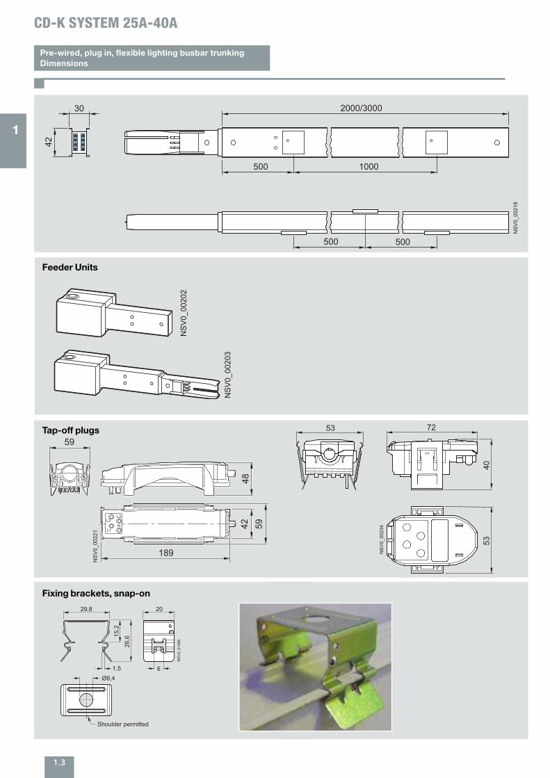
Pre-wired, plug in, flexible lighting busbar trunkingDimensions
Feeder Units
2000/3000
500 1000
500 500
NS
V0_
0021
8
42
30
CD-K SYSTEM 25A-40A
NS
V0_
0020
2
L2
NL3
L1
48
59
189
42 59
NS
V0_
0022
1
53
NS
V0_
0023
4
72
5340
NS
V0_
0020
3
Tap-off plugs
Fixing brackets, snap-on
1
1.4
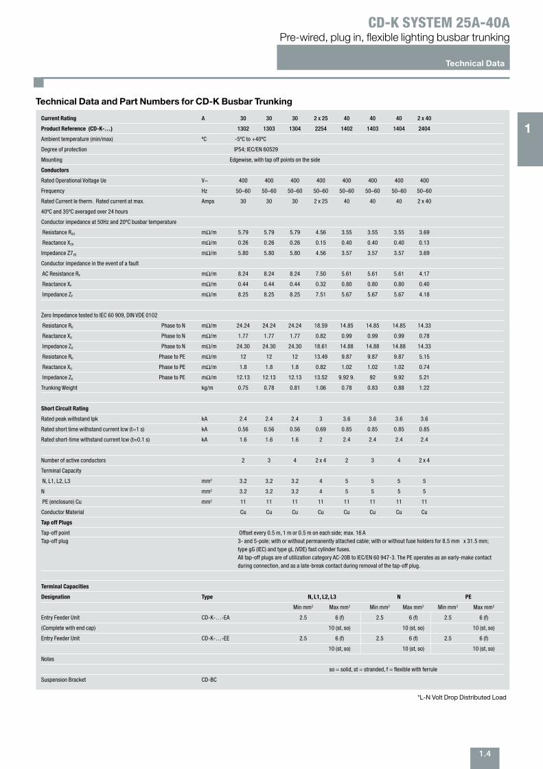
Technical Data and Part Numbers for CD-K Busbar Trunking
*L-N Volt Drop Distributed Load
Technical Data
Pre-wired, plug in, flexible lighting busbar trunkingCD-K SYSTEM 25A-40A
Current Rating A 30 30 30 2 x 25 40 40 40 2 x 40
Product Reference (CD-K-…) 1302 1303 1304 2254 1402 1403 1404 2404
Ambient temperature (min/max) ºC -5ºC to +40ºC
Degree of protection IP54; IEC/EN 60529
Mounting Edgewise, with tap off points on the side
Conductors
Rated Operational Voltage Ue V~ 400 400 400 400 400 400 400 400
Frequency Hz 50–60 50–60 50–60 50–60 50–60 50–60 50–60 50–60
Rated Current Ie therm. Rated current at max. Amps 30 30 30 2 x 25 40 40 40 2 x 40
40ºC and 35ºC averaged over 24 hours
Conductor impedance at 50Hz and 20ºC busbar temperature
Resistance R20 mΩ/m 5.79 5.79 5.79 4.56 3.55 3.55 3.55 3.69
Reactance X20 mΩ/m 0.26 0.26 0.26 0.15 0.40 0.40 0.40 0.13
Impedance Z720 mΩ/m 5.80 5.80 5.80 4.56 3.57 3.57 3.57 3.69
Conductor impedance in the event of a fault
AC Resistance RF mΩ/m 8.24 8.24 8.24 7.50 5.61 5.61 5.61 4.17
Reactance XF mΩ/m 0.44 0.44 0.44 0.32 0.80 0.80 0.80 0.40
Impedance ZF mΩ/m 8.25 8.25 8.25 7.51 5.67 5.67 5.67 4.18
Zero Impedance tested to IEC 60 909, DIN VDE 0102
Resistance R0 Phase to N mΩ/m 24.24 24.24 24.24 18.59 14.85 14.85 14.85 14.33
Reactance X0 Phase to N mΩ/m 1.77 1.77 1.77 0.82 0.99 0.99 0.99 0.78
Impedance Z0 Phase to N mΩ/m 24.30 24.30 24.30 18.61 14.88 14.88 14.88 14.33
Resistance R0 Phase to PE mΩ/m 12 12 12 13.49 9.87 9.87 9.87 5.15
Reactance X0 Phase to PE mΩ/m 1.8 1.8 1.8 0.82 1.02 1.02 1.02 0.74
Impedance Z0 Phase to PE mΩ/m 12.13 12.13 12.13 13.52 9.92 9. 92 9.92 5.21
Trunking Weight kg/m 0.75 0.78 0.81 1.06 0.78 0.83 0.88 1.22
Short Circuit Rating
Rated peak withstand Ipk kA 2.4 2.4 2.4 3 3.6 3.6 3.6 3.6
Rated short time withstand current Icw (t=1 s) kA 0.56 0.56 0.56 0.69 0.85 0.85 0.85 0.85
Rated short-time withstand current Icw (t=0.1 s) kA 1.6 1.6 1.6 2 2.4 2.4 2.4 2.4
Number of active conductors 2 3 4 2 x 4 2 3 4 2 x 4
Terminal Capacity
N, L1, L2, L3 mm2 3.2 3.2 3.2 4 5 5 5 5
N mm2 3.2 3.2 3.2 4 5 5 5 5
PE (enclosure) Cu mm2 11 11 11 11 11 11 11 11
Conductor Material Cu Cu Cu Cu Cu Cu Cu Cu
Tap off Plugs
Tap-off point Offset every 0.5 m, 1 m or 0.5 m on each side; max. 16 A Tap-off plug 3- and 5-pole; with or without permanently attached cable; with or without fuse holders for 8.5 mm x 31.5 mm;
type gG (IEC) and type gL (VDE) fast cylinder fuses. All tap-off plugs are of utilization category AC-20B to IEC/EN 60 947-3. The PE operates as an early-make contactduring connection, and as a late-break contact during removal of the tap-off plug.
Terminal Capacities
Designation Type N, L1, L2, L3 N PE
Min mm2 Max mm2 Min mm2 Max mm2 Min mm2 Max mm2
Entry Feeder Unit CD-K-…-EA 2.5 6 (f) 2.5 6 (f) 2.5 6 (f)
(Complete with end cap) 10 (st, so) 10 (st, so) 10 (st, so)
Entry Feeder Unit CD-K-…-EE 2.5 6 (f) 2.5 6 (f) 2.5 6 (f)
10 (st, so) 10 (st, so) 10 (st, so)
Notes
so = solid, st = stranded, f = flexible with ferrule
Suspension Bracket CD-BC
1
2.1
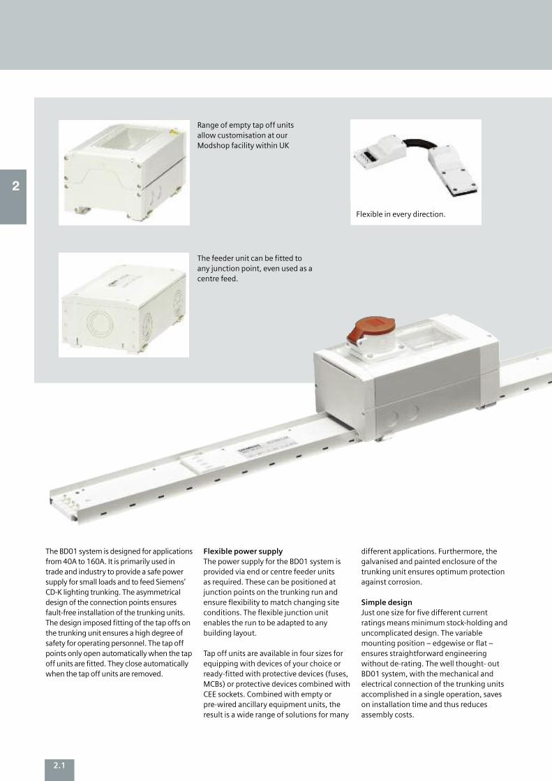
Range of empty tap off unitsallow customisation at ourModshop facility within UK
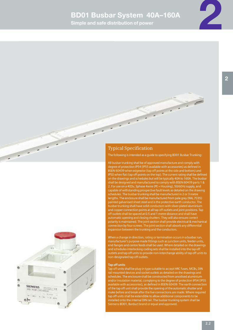
The BD01 system is designed for applicationsfrom 40A to 160A. It is primarily used intrade and industry to provide a safe powersupply for small loads and to feed Siemens’CD-K lighting trunking. The asymmetricaldesign of the connection points ensuresfault-free installation of the trunking units.The design imposed fitting of the tap offs onthe trunking unit ensures a high degree ofsafety for operating personnel. The tap offpoints only open automatically when the tapoff units are fitted. They close automaticallywhen the tap off units are removed.
Flexible power supplyThe power supply for the BD01 system is provided via end or centre feeder units as required. These can be positioned at junction points on the trunking run and ensure flexibility to match changing site conditions. The flexible junction unitenables the run to be adapted to anybuilding layout.
Tap off units are available in four sizes forequipping with devices of your choice orready-fitted with protective devices (fuses,MCBs) or protective devices combined withCEE sockets. Combined with empty orpre-wired ancillary equipment units, theresult is a wide range of solutions for many
different applications. Furthermore, thegalvanised and painted enclosure of thetrunking unit ensures optimum protectionagainst corrosion.
Simple design Just one size for five different currentratings means minimum stock-holding anduncomplicated design. The variablemounting position – edgewise or flat –ensures straightforward engineeringwithout de-rating. The well thought- outBD01 system, with the mechanical andelectrical connection of the trunking units accomplished in a single operation, saveson installation time and thus reducesassembly costs.
The feeder unit can be fitted toany junction point, even used as acentre feed.
Flexible in every direction.
2
2.2
The following is intended as a guide to specifying BD01 Busbar Trunking:
All busbar trunking shall be of approved manufacture and comply withdegree of protection IP54 (IP55 available with accessories) as defined inBSEN 60439 when edgewise (tap off points at the side and bottom) andIP50 when flat (tap off points on the top). The current rating shall be definedon the drawings and schedules but will be typically 40A to 160A. The busbarshall be designed and manufactured to comply with BSEN 60439 parts 1 &2. For use on a 400v, 3phase 4wire (PE = Housing), 50/60Hz supply, andcapable of withstanding prospective fault levels as detailed on the drawingschedules. The busbar trunking shall be manufactured in 2 or 3 metrelengths. The enclosure shall be manufactured from pale grey (RAL 7035)painted galvanised sheet steel and is the protective earth conductor. Thebusbar trunking shall have solid conductors with silver-plated aluminiumand copper connection points at all tap off outlets and joint positions. Tapoff outlets shall be spaced at 0.5 and 1 metre distance and shall haveautomatic opening and closing shutters. They will also ensure correctpolarity is maintained. The joint section shall provide electrical & mechanicalconnection by four screws. The joint section shall absorb any differentialexpansion between the trunking and the conductors.
When a change in direction, rating or termination occurs in a busbar run,manufacturer’s purpose made fittings such as junction units, feeder units,end flanges and centre feeds shall be used. Where detailed on the drawingsand schedules interlocking coding sets shall be installed into the tap offoutlets and tap off units to provide non-interchange ability of tap off units tonon-designated tap off outlets.
Tap off units Tap off units shall be plug-in type suitable to accept HRC fuses, MCBs, DINrail mounted devices and socket outlets as detailed on the drawings andschedules. The enclosure shall be constructed from anodised aluminiumand/or insulation material, complying to the degree of protection IP54 (IP55available with accessories), as defined in BSEN 60439. The earth connectionof the tap off unit shall provide the opening of the automatic shutter andmake before and break after the live connections are made. Where requiredtap off units shall be extendible to allow additional components to beinstalled onto the internal DIN rail. The busbar trunking system shall beSiemens BD01, Barduct brand or equal and approved.
Typical Specification
2
2BD01 Busbar System 40A–160ASimple and safe distribution of power

2.3
Small current plug-in distribution BusbarTechnical Data
Simple and safe distribution of power BD01 Busbar System 40A–160A
Product Reference – Current Rating BD01-40 BD01-63 BD01-100 BD01-125 BD01-160
Current paths
Rated Operational Voltage Ue V~ 400 400 400 400 400
Frequency Hz 50–60 50–60 50–60 50–60 50–60
Rated Current Ie therm. Rated current at max. 40ºC and 35ºC A 4 0 63 100 125 160
averaged over 24 hours
Conductor impedance at 50Hz and 20ºC busbar temperature
Resistance R20 mΩ/m 3.960 1.936 0.938 0.910 0.578
Reactance X20 mΩ/m 0.280 0.324 0.286 0.300 0.273
Impedance Z720 mΩ/m 3.970 1.968 0.994 1.000 0.642
Conductor impedance in the event of a fault
AC Resistance RF mΩ/m 5.991 4.128 2.841 2.420 2.189
Reactance XF mΩ/m 1.396 1.248 1.186 0.940 0.973
Impedance ZF mΩ/m 6.151 4.312 3.078 2.600 2.395
L-L Volt Drop Distributed Load
mV/A/m pf 0.7 2.57 1.37 0.75 0.74 0.52
mV/A/m pf 0.8 2.89 1.51 0.80 0.79 0.54
mV/A/m pf 0.9 3.19 1.63 0.84 0.82 0.55
mV/A/m pf 1 3.43 1.68 0.81 0.79 0.50
Zero Impedance tested to IEC 60 909, DIN VDE 0102
Resistance R0 Phase to N mΩ/m 15.904 7.911 4.115 3.810 3.167
Reactance X0 Phase to N mΩ/m 2.128 2.058 1.797 1.630 1.656
Impedance Z0 Phase to N mΩ/m 16.045 8.175 4.490 4.140 3.574
Resistance R0 Phase to PE mΩ/m 10.086 8.565 6.648 5.430 5.343
Reactance X0 Phase to PE mΩ/m 2.909 3.338 3.067 2.320 2.355
Impedance Z0 Phase to PE mΩ/m 10.498 9.183 7.322 5.910 5.839
Short Circuit RatingRated peak withstand Ipk kA 2.55 6.30 15.30 15.30 15.30
Rated short time withstand current Icw (t=1 s) kA 0.58 1.15 2.50 2.50 2.50
Rated short-time withstand current Icw (t=0.1 s) kA 1.70 4.20 9.00 9.00 9.00
Number of active conductors 4 4 4 4 4
Conductor cross-section
L1, L2, L3 mm2 7.9 15.7 34.1 34.1 34.1
N mm2 7.9 15.7 34.1 34.1 34.1
PE (enclosure) Cu mm2 20.0 20.0 20.0 20.0 20.0
Conductor Material Al Al Al Al Cu
Max. interval between trunking unit edgewise m 3 3 3 3 3
supports at normal mechanical load flat m 1.5 1.5 1.5 1.5 1.5
Combustive Energy kWh/m 0.76 0.76 0.76 0.76 0.76
Trunking Weight kg/m 1.45 1.55 1.75 1.75 2.65
Tap off Units
Rated Operational Voltage Ue V 230 or 400
Rated Current Ie max. A 63
Switching capacity of the built-in switch-disconnector AC-20B
Terminal Capacities L1, L2, L3 N PE Type min mm2 max mm2 min mm2 max mm2 min mm2 max mm2
Feeder units BD01-E 6 (e, m) 50 (m) 6 (e, m) 50 (m) 6 (e, m) 50 (m)
BD01-160-E 25 (m) 95 (m) 25 (m) 95 (m) 16 (m) 50 (m)
Tap off units BD01-AK01X/ZS 0.75 (f, st) 10 (f, so, st) 0.75 (f, st) 10 (f, so, st) 0.75 (f, st) 10 (f, so, st)
BD01-AK02X/ZS3 0.75 (f, st) 10 (f, so, st) 0.75 (f, st) 10 (f, so, st) 0.75 (f, st) 10 (f, so, st)
BD01-AK02M0/A163 0.75 (so, st) 16 (so) 0.75 (f, st) 10 (f, so, st) 0.75 (f, st) 10 (f, so, st)
BD01-AK02M0/A323 0.75 (so, st) 16 (so) 0.75 (f, st) 10 (f, so, st) 0.75 (f, st) 10 (f, so, st)
BD01-AK1M1/A101 0.75 (so, st) 16 (so) 0.75 (so, f) 2.5 (so, f) 0.75 (so, f) 2.5 (so, f)
BD01-AK1M1/A161 0.75 (so, st) 17 (so) 0.75 (so, f) 2.5 (so, f) 0.75 (so, f) 2.5 (so, f)
BD01-AK1M1/A321 0.75 (so, st) 18 (so) 0.75 (so, f) 2.5 (so, f) 0.75 (so, f) 2.5 (so, f)
BD01-AK1M1/A... 0.75 (so, st) 16 (so) 0.75 (f, st) 10 (f, so, st) 0.75 (so, st) 16 (so)
BD01-AK1M1/A...N 0.75 (so, st) 16 (so) 0.75 (so, st) 16 (so) 0.75 (so, st) 16 (so)
BD01-AK1X/S14 0.50 (f, st) 4 (so) 0.75 (f, st) 10 (f, so, st) 0.75 (so, st) 16 (so)
Notes: BD01-AK1X/S18 0.50 (f, st) 16 (f, so, st) 0.75 (f, st) 10 (f, so, st) 0.75 (so, st) 16 (so)
BD01-AK1X/GB... 0.75 (so, st) 16 (so) 0.75 (f, st) 10 (f, so, st) 0.75 (so, st) 16 (so)
so = solid BD01-AK2X/F1451 0.75 (so, st) 16 (so) 0.75 (f, st) 10 (f, so, st) 0.75 (so, st) 16 (so)
st = stranded BD01-AK2X/S27 0.75 (f, st) 10 (f, so, st) 0.75 (f, st) 10 (f, so, st) 0.75 (so, st) 16 (so)
f = flexible with ferrule BD01-AK2HX/S33 1.50 (f, st) 25 (f, st) 0.75 (f, st) 10 (f, so, st) 0.75 (so, st) 16 (so, st)
2
2.4
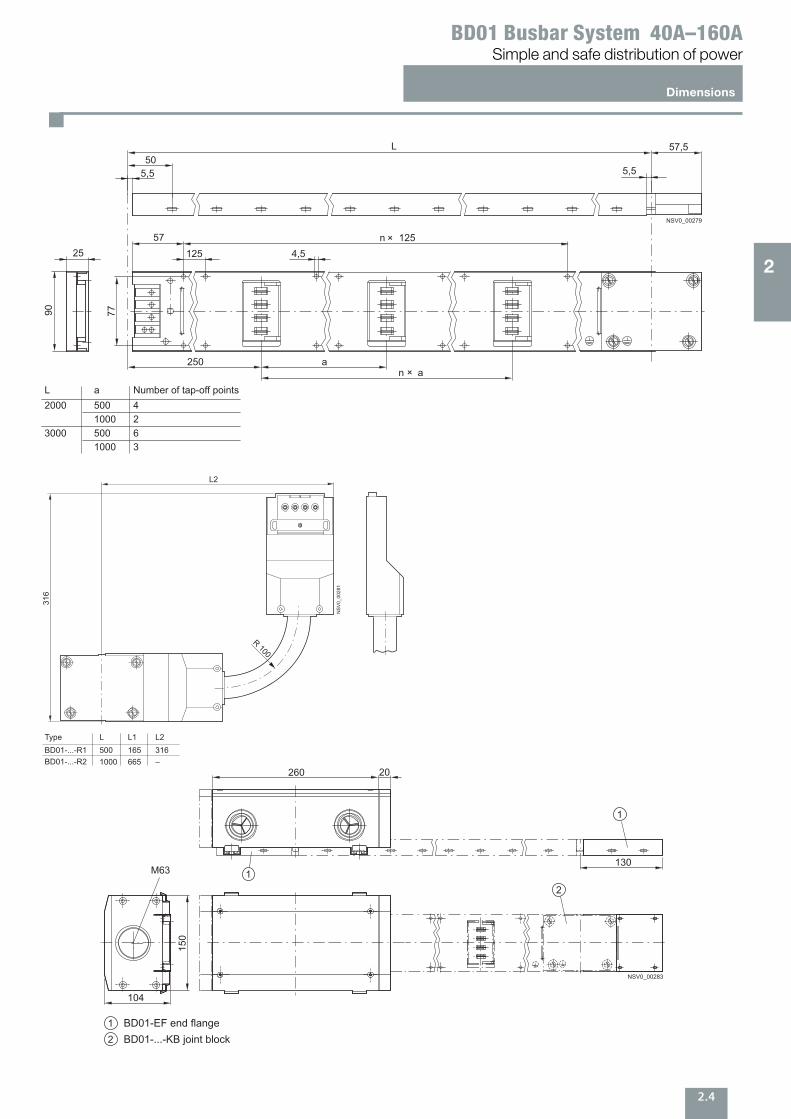
Dimensions
Simple and safe distribution of power BD01 Busbar System 40A–160A
L50
25
90 77
57125
250 a
n 125×
n a×
NSV0_00279
L a Number of tap-off points2000 500 4
3000 500 61000 3
1000 2
4,5
5,5
57,5
5,5
R 100
316
L2
NS
V0_
0028
1
Type LBD01-...-R1BD01-...-R2
5001000
L1165665
L2316–
1
12
20260
130
150
104
M63
NSV0_00283
1 BD01-EF end flange2 BD01-...-KB joint block
2
3.1
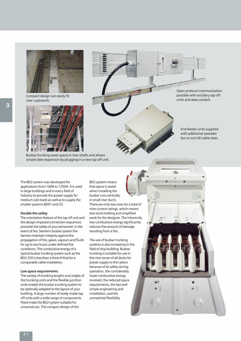
Compact design can easily fit riser cupboards.
End feeder units suppliedwith additional spreaderbox to suit UK cable sizes.
Busbar trunking saves space in riser shafts and allowssimple later expansion by plugging in a new tap off unit.
The BD2 system was developed forapplications from 160A to 1250A. It is usedin large buildings and in every field ofindustry to provide the power supply formedium-size loads as well as to supply thesmaller systems BD01 and CD.
Double the safety The orientation feature of the tap off unit andthe design-imposed connection sequencespromote the safety of your personnel. In theevent of fire, Siemens busbar system firebarriers maintain integrity against thepropagation of fire, gases, vapours and fluidsfor up to two hours under defined fireconditions. The combustive energy of atypical busbar trunking system such as theBD2-250 is less than a third of that for acomparable cable installation.
Low space requirements The variety of trunking lengths and angles ofthe trunking units and the flexible junctionunits enable the busbar trunking system tobe optimally adapted to the layout of yourbuilding. A large number of ready-made tapoff units with a wide range of componentsfitted make the BD2 system suitable foruniversal use. The compact design of the
BD2 system meansthat space is savedwhen installing thebusbar runs verticallyin small riser ducts.There are only two sizes for a total ofnine current ratings, which meansless stock-holding and simplifiedwork for the designer. The inherentlylow combustive energy significantlyreduces the amount of damageresulting from a fire.
The use of busbar trunkingsystems is also increasing in thefield of ship building. Busbartrunking is suitable for use inthe riser zones of all decks forpower supply to the cabinsbecause of its safety duringoperation, the considerablylower combustive energyinvolved, the reduced spacerequirements, the fast andsimple engineering andinstallation, and theunmatched flexibility.
Open protocol communication possible with ancillary tap off units and data conduit.
3
3.2
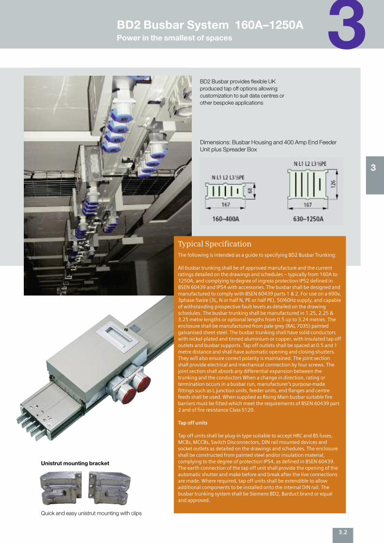
BD2 Busbar provides flexible UKproduced tap off options allowingcustomization to suit data centres orother bespoke applications
Unistrut mounting bracket
Quick and easy unistrut mounting with clips
3
The following is intended as a guide to specifying BD2 Busbar Trunking:
All busbar trunking shall be of approved manufacture and the currentratings detailed on the drawings and schedules – typically from 160A to1250A, and complying to degree of ingress protection IP52 defined inBSEN 60439 and IP54 with accessories. The busbar shall be designed andmanufactured to comply with BSEN 60439 parts 1 & 2. For use on a 690v,3phase 5wire (3L, N or half N, PE or half PE), 50/60Hz supply, and capableof withstanding prospective fault levels as detailed on the drawingschedules. The busbar trunking shall be manufactured in 1.25, 2.25 &3.25 metre lengths or optional lengths from 0.5 up to 3.24 metres. Theenclosure shall be manufactured from pale grey (RAL 7035) paintedgalvanised sheet steel. The busbar trunking shall have solid conductorswith nickel-plated and tinned aluminium or copper, with insulated tap offoutlets and busbar supports. Tap off outlets shall be spaced at 0.5 and 1metre distance and shall have automatic opening and closing shutters.They will also ensure correct polarity is maintained. The joint sectionshall provide electrical and mechanical connection by four screws. Thejoint section shall absorb any differential expansion between thetrunking and the conductors When a change in direction, rating ortermination occurs in a busbar run, manufacturer’s purpose-madefittings such as L junction units, feeder units, end flanges and centrefeeds shall be used. When supplied as Rising Main busbar suitable firebarriers must be fitted which meet the requirements of BSEN 60439 part2 and of fire resistance Class S120.
Tap off units
Tap off units shall be plug-in type suitable to accept HRC and BS fuses,MCBs, MCCBs, Switch Disconnectors, DIN rail mounted devices andsocket outlets as detailed on the drawings and schedules. The enclosureshall be constructed from painted steel and/or insulation material,complying to the degree of protection IP54, as defined in BSEN 60439.The earth connection of the tap off unit shall provide the opening of theautomatic shutter and make before and break after the live connectionsare made. Where required, tap off units shall be extendible to allowadditional components to be installed onto the internal DIN rail. Thebusbar trunking system shall be Siemens BD2, Barduct brand or equaland approved.
Typical Specification
3BD2 Busbar System 160A–1250APower in the smallest of spaces
Dimensions: Busbar Housing and 400 Amp End FeederUnit plus Spreader Box
3.3
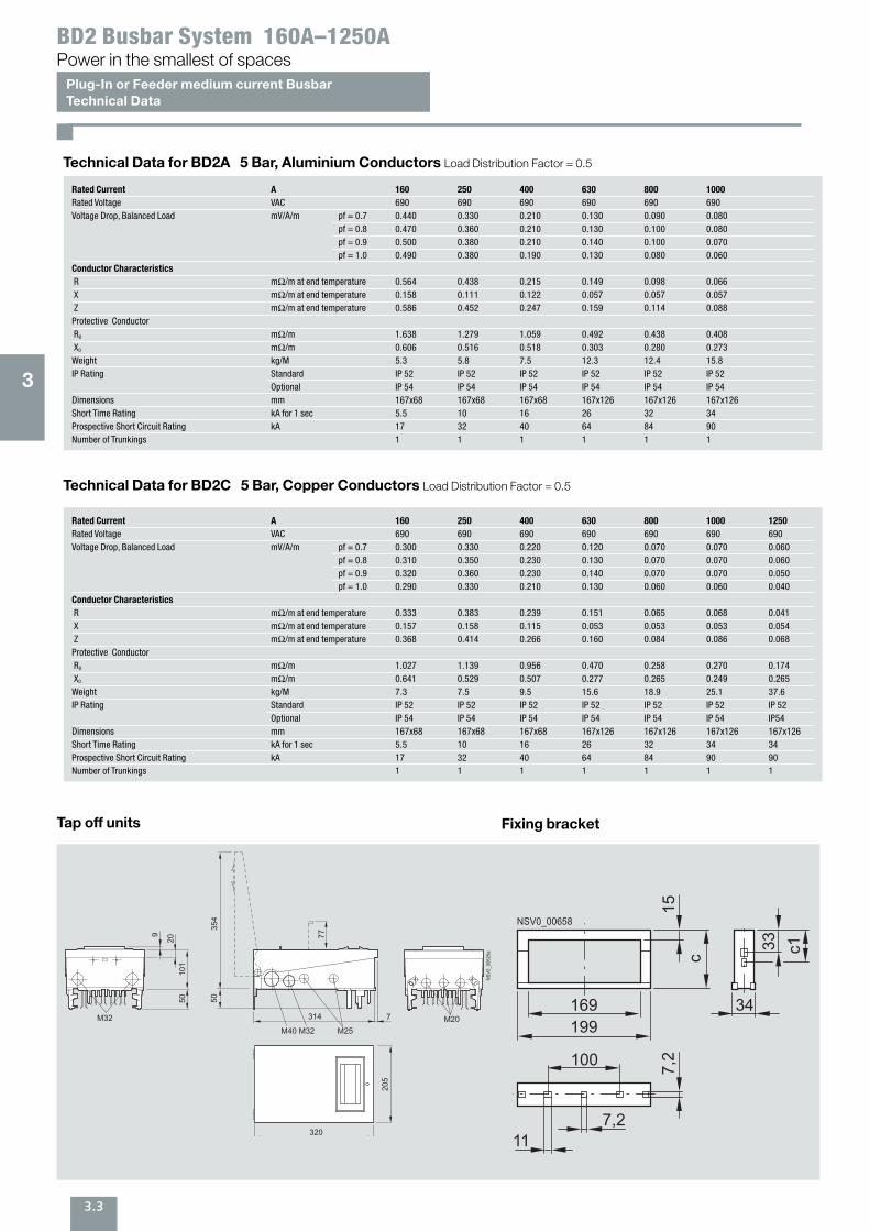
Plug-In or Feeder medium current BusbarTechnical Data
Power in the smallest of spacesBD2 Busbar System 160A–1250A
Technical Data for BD2A 5 Bar, Aluminium Conductors Load Distribution Factor = 0.5
Rated Current A 160 250 400 630 800 1000
Rated Voltage VAC 690 690 690 690 690 690 Voltage Drop, Balanced Load mV/A/m pf = 0.7 0.440 0.330 0.210 0.130 0.090 0.080
pf = 0.8 0.470 0.360 0.210 0.130 0.100 0.080 pf = 0.9 0.500 0.380 0.210 0.140 0.100 0.070 pf = 1.0 0.490 0.380 0.190 0.130 0.080 0.060
Conductor Characteristics
R mΩ/m at end temperature 0.564 0.438 0.215 0.149 0.098 0.066 X mΩ/m at end temperature 0.158 0.111 0.122 0.057 0.057 0.057 Z mΩ/m at end temperature 0.586 0.452 0.247 0.159 0.114 0.088 Protective Conductor R0 mΩ/m 1.638 1.279 1.059 0.492 0.438 0.408 X0 mΩ/m 0.606 0.516 0.518 0.303 0.280 0.273 Weight kg/M 5.3 5.8 7.5 12.3 12.4 15.8 IP Rating Standard IP 52 IP 52 IP 52 IP 52 IP 52 IP 52
Optional IP 54 IP 54 IP 54 IP 54 IP 54 IP 54 Dimensions mm 167x68 167x68 167x68 167x126 167x126 167x126 Short Time Rating kA for 1 sec 5.5 10 16 26 32 34 Prospective Short Circuit Rating kA 17 32 40 64 84 90 Number of Trunkings 1 1 1 1 1 1
Technical Data for BD2C 5 Bar, Copper Conductors Load Distribution Factor = 0.5
Rated Current A 160 250 400 630 800 1000 1250
Rated Voltage VAC 690 690 690 690 690 690 690 Voltage Drop, Balanced Load mV/A/m pf = 0.7 0.300 0.330 0.220 0.120 0.070 0.070 0.060
pf = 0.8 0.310 0.350 0.230 0.130 0.070 0.070 0.060 pf = 0.9 0.320 0.360 0.230 0.140 0.070 0.070 0.050pf = 1.0 0.290 0.330 0.210 0.130 0.060 0.060 0.040
Conductor Characteristics
R mΩ/m at end temperature 0.333 0.383 0.239 0.151 0.065 0.068 0.041 X mΩ/m at end temperature 0.157 0.158 0.115 0.053 0.053 0.053 0.054 Z mΩ/m at end temperature 0.368 0.414 0.266 0.160 0.084 0.086 0.068 Protective Conductor R0 mΩ/m 1.027 1.139 0.956 0.470 0.258 0.270 0.174 X0 mΩ/m 0.641 0.529 0.507 0.277 0.265 0.249 0.265 Weight kg/M 7.3 7.5 9.5 15.6 18.9 25.1 37.6 IP Rating Standard IP 52 IP 52 IP 52 IP 52 IP 52 IP 52 IP 52
Optional IP 54 IP 54 IP 54 IP 54 IP 54 IP 54 IP54 Dimensions mm 167x68 167x68 167x68 167x126 167x126 167x126 167x126 Short Time Rating kA for 1 sec 5.5 10 16 26 32 34 34Prospective Short Circuit Rating kA 17 32 40 64 84 90 90Number of Trunkings 1 1 1 1 1 1 1
3
Tap off units
5035
4
77
314 7
2010
150
9
M40 M32 M25M32 M20
NSV
0_00
625a
205
320
Fixing bracket
169199
33 c1
34
15
100
7,2
7,2
11
c
NSV0_00658
3.4
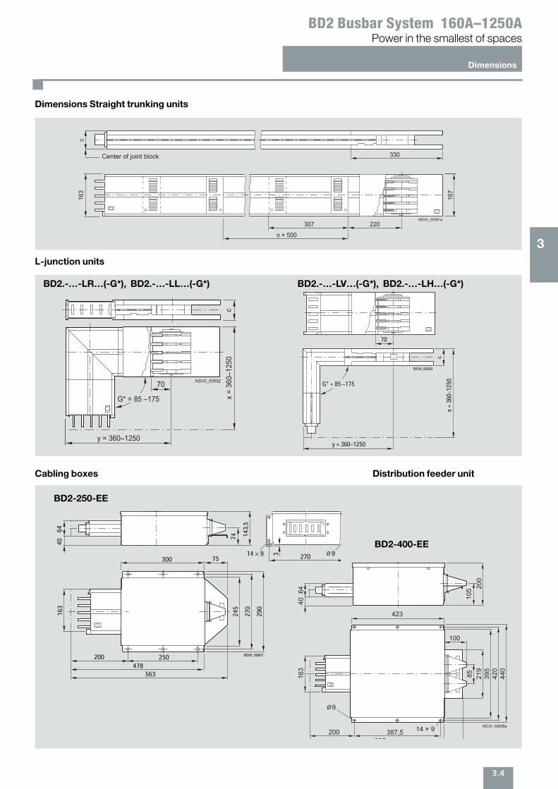
Dimensions
Power in the smallest of spacesBD2 Busbar System 160A–1250A
Dimensions Straight trunking units
L-junction units
Cabling boxes Distribution feeder unit
x =
360–
1250
G* = 85 –175
70
y = 360–1250
c
NSV0_00592
c / mm1
70
c
x =
360
–125
0y = 360–1250
G* = 85 –175
NSV0_00593
220NSV0_00591a
307
167
163
n × 500
330
c
Center of joint block
Length Number of tap-off points on both sidesn × 500
0.5 ... 1.251.26 ... 2.252.26 ... 3.25
–4 ... 88 ... 12On optional lengths, it may not be possible to fit tap-off units to all tap-off points
BD2.-…-LR…(-G*), BD2.-…-LL…(-G*) BD2.-…-LV…(-G*), BD2.-…-LH…(-G*)
9Ø
40
64
74 143,5
100
20270314 9
163
245
300
250200
75
NSV0_00607
270
290
478
563
NSV0_00608a
4064
105
219
85163
423
100
387,5605
200 14 × 9
687
200
395
420
440
9Ø
BD2-400-EE
BD2-250-EE
3
4.1
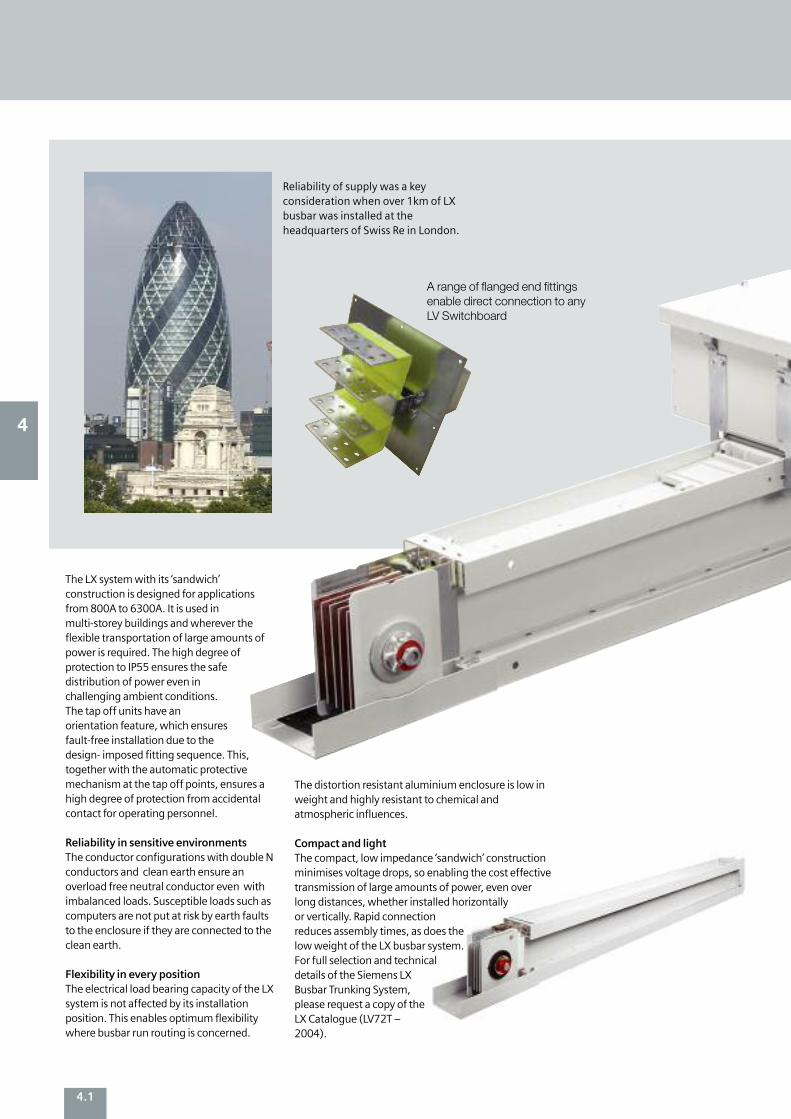
The LX system with its ‘sandwich’construction is designed for applicationsfrom 800A to 6300A. It is used inmulti-storey buildings and wherever theflexible transportation of large amounts ofpower is required. The high degree ofprotection to IP55 ensures the safedistribution of power even inchallenging ambient conditions.The tap off units have anorientation feature, which ensuresfault-free installation due to thedesign- imposed fitting sequence. This,together with the automatic protectivemechanism at the tap off points, ensures ahigh degree of protection from accidentalcontact for operating personnel.
Reliability in sensitive environments The conductor configurations with double Nconductors and clean earth ensure anoverload free neutral conductor even withimbalanced loads. Susceptible loads such ascomputers are not put at risk by earth faultsto the enclosure if they are connected to theclean earth.
Flexibility in every position The electrical load bearing capacity of the LXsystem is not affected by its installationposition. This enables optimum flexibilitywhere busbar run routing is concerned.
The distortion resistant aluminium enclosure is low inweight and highly resistant to chemical andatmospheric influences.
Compact and light The compact, low impedance ‘sandwich’ constructionminimises voltage drops, so enabling the cost effectivetransmission of large amounts of power, even overlong distances, whether installed horizontallyor vertically. Rapid connectionreduces assembly times, as does thelow weight of the LX busbar system.For full selection and technicaldetails of the Siemens LXBusbar Trunking System,please request a copy of theLX Catalogue (LV72T –2004).
Reliability of supply was a keyconsideration when over 1km of LXbusbar was installed at theheadquarters of Swiss Re in London.
4
A range of flanged end fittingsenable direct connection to anyLV Switchboard
4.2
4
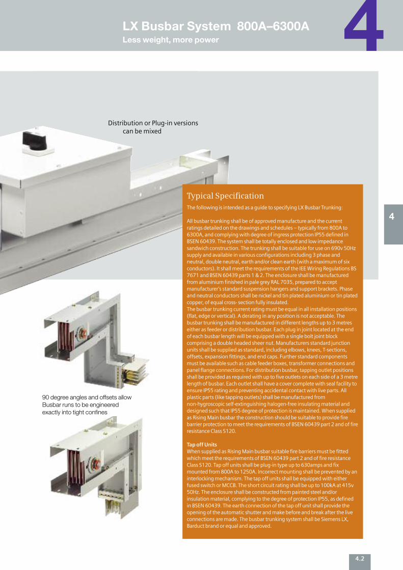
Distribution or Plug-in versionscan be mixed
The following is intended as a guide to specifying LX Busbar Trunking:
All busbar trunking shall be of approved manufacture and the currentratings detailed on the drawings and schedules – typically from 800A to6300A, and complying with degree of ingress protection IP55 defined inBSEN 60439. The system shall be totally enclosed and low impedancesandwich construction. The trunking shall be suitable for use on 690v 50Hzsupply and available in various configurations including 3 phase andneutral, double neutral, earth and/or clean earth (with a maximum of sixconductors). It shall meet the requirements of the IEE Wiring Regulations BS7671 and BSEN 60439 parts 1 & 2. The enclosure shall be manufacturedfrom aluminium finished in pale grey RAL 7035, prepared to acceptmanufacturer’s standard suspension hangers and support brackets. Phaseand neutral conductors shall be nickel and tin plated aluminium or tin platedcopper, of equal cross- section fully insulated. The busbar trunking current rating must be equal in all installation positions(flat, edge or vertical). A derating in any position is not acceptable. Thebusbar trunking shall be manufactured in different lengths up to 3 metreseither as feeder or distribution busbar. Each plug in joint located at the endof each busbar length will be equipped with a single bolt joint blockcomprising a double headed sheer nut. Manufacturers standard junctionunits shall be supplied as standard, including elbows, knees, T-sections,offsets, expansion fittings, and end caps. Further standard componentsmust be available such as cable feeder boxes, transformer connections andpanel flange connections. For distribution busbar, tapping outlet positionsshall be provided as required with up to five outlets on each side of a 3 metrelength of busbar. Each outlet shall have a cover complete with seal facility toensure IP55 rating and preventing accidental contact with live parts. Allplastic parts (like tapping outlets) shall be manufactured fromnon-hygroscopic self-extinguishing halogen-free insulating material anddesigned such that IP55 degree of protection is maintained. When suppliedas Rising Main busbar the construction should be suitable to provide firebarrier protection to meet the requirements of BSEN 60439 part 2 and of fireresistance Class S120.
Tap off Units When supplied as Rising Main busbar suitable fire barriers must be fittedwhich meet the requirements of BSEN 60439 part 2 and of fire resistanceClass S120. Tap off units shall be plug-in type up to 630amps and fixmounted from 800A to 1250A. Incorrect mounting shall be prevented by aninterlocking mechanism. The tap off units shall be equipped with eitherfused switch or MCCB. The short circuit rating shall be up to 100kA at 415v50Hz. The enclosure shall be constructed from painted steel and/orinsulation material, complying to the degree of protection IP55, as definedin BSEN 60439. The earth connection of the tap off unit shall provide theopening of the automatic shutter and make before and break after the live connections are made. The busbar trunking system shall be Siemens LX,Barduct brand or equal and approved.
Typical Specification
4LX Busbar System 800A–6300ALess weight, more power
90 degree angles and offsets allowBusbar runs to be engineeredexactly into tight confines
4.3
High current Low Impedance sandwich BusbarTechnical Data
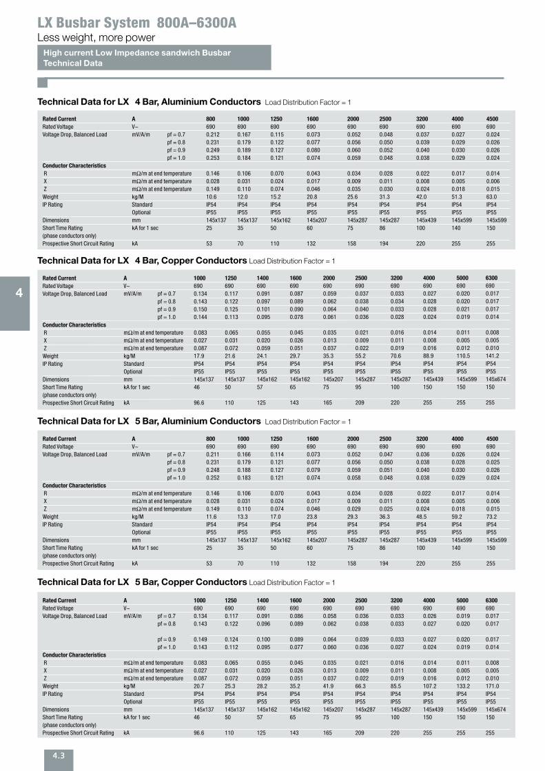
Less weight, more powerLX Busbar System 800A–6300A
Technical Data for LX 4 Bar, Aluminium Conductors Load Distribution Factor = 1
Technical Data for LX 4 Bar, Copper Conductors Load Distribution Factor = 1
Rated Current A 800 1000 1250 1600 2000 2500 3200 4000 4500
Rated Voltage V~ 690 690 690 690 690 690 690 690 690 Voltage Drop, Balanced Load mV/A/m pf = 0.7 0.212 0.167 0.115 0.073 0.052 0.048 0.037 0.027 0.024
pf = 0.8 0.231 0.179 0.122 0.077 0.056 0.050 0.039 0.029 0.026 pf = 0.9 0.249 0.189 0.127 0.080 0.060 0.052 0.040 0.030 0.026 pf = 1.0 0.253 0.184 0.121 0.074 0.059 0.048 0.038 0.029 0.024
Conductor Characteristics
R mΩ/m at end temperature 0.146 0.106 0.070 0.043 0.034 0.028 0.022 0.017 0.014 X mΩ/m at end temperature 0.028 0.031 0.024 0.017 0.009 0.011 0.008 0.005 0.006 Z mΩ/m at end temperature 0.149 0.110 0.074 0.046 0.035 0.030 0.024 0.018 0.015 Weight kg/M 10.6 12.0 15.2 20.8 25.6 31.3 42.0 51.3 63.0 IP Rating Standard IP54 IP54 IP54 IP54 IP54 IP54 IP54 IP54 IP54
Optional IP55 IP55 IP55 IP55 IP55 IP55 IP55 IP55 IP55 Dimensions mm 145x137 145x137 145x162 145x207 145x287 145x287 145x439 145x599 145x599Short Time Rating kA for 1 sec 25 35 50 60 75 86 100 140 150 (phase conductors only)Prospective Short Circuit Rating kA 53 70 110 132 158 194 220 255 255
Rated Current A 1000 1250 1400 1600 2000 2500 3200 4000 5000 6300
Rated Voltage V~ 690 690 690 690 690 690 690 690 690 690 Voltage Drop, Balanced Load mV/A/m pf = 0.7 0.134 0.117 0.091 0.087 0.059 0.037 0.033 0.027 0.020 0.017
pf = 0.8 0.143 0.122 0.097 0.089 0.062 0.038 0.034 0.028 0.020 0.017 pf = 0.9 0.150 0.125 0.101 0.090 0.064 0.040 0.033 0.028 0.021 0.017 pf = 1.0 0.144 0.113 0.095 0.078 0.061 0.036 0.028 0.024 0.019 0.014
Conductor Characteristics
R mΩ/m at end temperature 0.083 0.065 0.055 0.045 0.035 0.021 0.016 0.014 0.011 0.008 X mΩ/m at end temperature 0.027 0.031 0.020 0.026 0.013 0.009 0.011 0.008 0.005 0.005 Z mΩ/m at end temperature 0.087 0.072 0.059 0.051 0.037 0.022 0.019 0.016 0.012 0.010 Weight kg/M 17.9 21.6 24.1 29.7 35.3 55.2 70.6 88.9 110.5 141.2 IP Rating Standard IP54 IP54 IP54 IP54 IP54 IP54 IP54 IP54 IP54 IP54
Optional IP55 IP55 IP55 IP55 IP55 IP55 IP55 IP55 IP55 IP55Dimensions mm 145x137 145x137 145x162 145x162 145x207 145x287 145x287 145x439 145x599 145x674Short Time Rating kA for 1 sec 46 50 57 65 75 95 100 150 150 150 (phase conductors only)Prospective Short Circuit Rating kA 96.6 110 125 143 165 209 220 255 255 255
Technical Data for LX 5 Bar, Aluminium Conductors Load Distribution Factor = 1
Technical Data for LX 5 Bar, Copper Conductors Load Distribution Factor = 1
Rated Current A 800 1000 1250 1600 2000 2500 3200 4000 4500
Rated Voltage V~ 690 690 690 690 690 690 690 690 690 Voltage Drop, Balanced Load mV/A/m pf = 0.7 0.211 0.166 0.114 0.073 0.052 0.047 0.036 0.026 0.024
pf = 0.8 0.231 0.179 0.121 0.077 0.056 0.050 0.038 0.028 0.025 pf = 0.9 0.248 0.188 0.127 0.079 0.059 0.051 0.040 0.030 0.026pf = 1.0 0.252 0.183 0.121 0.074 0.058 0.048 0.038 0.029 0.024
Conductor Characteristics
R mΩ/m at end temperature 0.146 0.106 0.070 0.043 0.034 0.028 0.022 0.017 0.014 X mΩ/m at end temperature 0.028 0.031 0.024 0.017 0.009 0.011 0.008 0.005 0.006 Z mΩ/m at end temperature 0.149 0.110 0.074 0.046 0.029 0.025 0.024 0.018 0.015Weight kg/M 11.6 13.3 17.0 23.8 29.3 36.3 48.5 59.2 73.2 IP Rating Standard IP54 IP54 IP54 IP54 IP54 IP54 IP54 IP54 IP54
Optional IP55 IP55 IP55 IP55 IP55 IP55 IP55 IP55 IP55 Dimensions mm 145x137 145x137 145x162 145x207 145x287 145x287 145x439 145x599 145x599Short Time Rating kA for 1 sec 25 35 50 60 75 86 100 140 150(phase conductors only)Prospective Short Circuit Rating kA 53 70 110 132 158 194 220 255 255
Rated Current A 1000 1250 1400 1600 2000 2500 3200 4000 5000 6300
Rated Voltage V~ 690 690 690 690 690 690 690 690 690 690 Voltage Drop, Balanced Load mV/A/m pf = 0.7 0.134 0.117 0.091 0.086 0.058 0.036 0.033 0.026 0.019 0.017
pf = 0.8 0.143 0.122 0.096 0.089 0.062 0.038 0.033 0.027 0.020 0.017
pf = 0.9 0.149 0.124 0.100 0.089 0.064 0.039 0.033 0.027 0.020 0.017 pf = 1.0 0.143 0.112 0.095 0.077 0.060 0.036 0.027 0.024 0.019 0.014
Conductor Characteristics
R mΩ/m at end temperature 0.083 0.065 0.055 0.045 0.035 0.021 0.016 0.014 0.011 0.008 X mΩ/m at end temperature 0.027 0.031 0.020 0.026 0.013 0.009 0.011 0.008 0.005 0.005 Z mΩ/m at end temperature 0.087 0.072 0.059 0.051 0.037 0.022 0.019 0.016 0.012 0.010 Weight kg/M 20.7 25.3 28.2 35.2 41.9 66.3 85.5 107.2 133.2 171.0 IP Rating Standard IP54 IP54 IP54 IP54 IP54 IP54 IP54 IP54 IP54 IP54
Optional IP55 IP55 IP55 IP55 IP55 IP55 IP55 IP55 IP55 IP55Dimensions mm 145x137 145x137 145x162 145x162 145x207 145x287 145x287 145x439 145x599 145x674Short Time Rating kA for 1 sec 46 50 57 65 75 95 100 150 150 150 (phase conductors only)Prospective Short Circuit Rating kA 96.6 110 125 143 165 209 220 255 255 255
4
4.4
Technical Data
Less weight, more powerLX Busbar System 800A–6300A
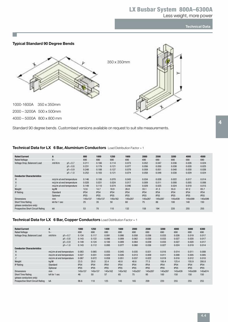
Typical Standard 90 Degree Bends
350 x 350mm
1000-1600A 350 x 350mm
2000 – 3200A 500 x 500mm
4000 – 5000A 800 x 800 mm
Standard 90 degree bends. Customised versions available on request to suit site measurements.4
Technical Data for LX 6 Bar, Aluminium Conductors Load Distribution Factor = 1
Technical Data for LX 6 Bar, Copper Conductors Load Distribution Factor = 1
Rated Current A 800 1000 1250 1600 2000 2500 3200 4000 4500
Rated Voltage V~ 690 690 690 690 690 690 690 690 690 Voltage Drop, Balanced Load mV/A/m pf = 0.7 0.211 0.166 0.114 0.073 0.052 0.047 0.036 0.026 0.024
pf = 0.8 0.231 0.179 0.121 0.077 0.056 0.050 0.038 0.028 0.025 pf = 0.9 0.248 0.188 0.127 0.079 0.059 0.051 0.040 0.030 0.026 pf = 1.0 0.252 0.183 0.121 0.074 0.058 0.048 0.038 0.029 0.024
Conductor Characteristics
R mΩ/m at end temperature 0.146 0.106 0.070 0.043 0.034 0.028 0.022 0.017 0.014 X mΩ/m at end temperature 0.028 0.031 0.024 0.017 0.009 0.011 0.008 0.005 0.006 Z mΩ/m at end temperature 0.149 0.110 0.074 0.046 0.029 0.025 0.024 0.018 0.015 Weight kg/M 12.6 14.7 18.9 26.8 33.1 41.3 55.0 67.2 83.7 IP Rating Standard IP54 IP54 IP54 IP54 IP54 IP54 IP54 IP54 IP54
Optional IP55 IP55 IP55 IP55 IP55 IP55 IP55 IP55 IP55 Dimensions mm 145x137 145x137 145x162 145x207 145x287 145x287 145x439 145x599 145x599Short Time Rating kA for 1 sec 25 35 50 60 75 86 100 140 150 (phase conductors only)Prospective Short Circuit Rating kA 53 70 110 132 158 194 220 255 255
Rated Current A 1000 1250 1400 1600 2000 2500 3200 4000 5000 6300
Rated Voltage V~ 690 690 690 690 690 690 690 690 690 690 Voltage Drop, Balanced Load mV/A/m pf = 0.7 0.134 0.117 0.091 0.086 0.058 0.036 0.033 0.026 0.019 0.017
pf = 0.8 0.143 0.122 0.096 0.089 0.062 0.038 0.033 0.027 0.020 0.017 pf = 0.9 0.149 0.124 0.100 0.089 0.064 0.039 0.033 0.027 0.020 0.017 pf = 1.0 0.143 0.112 0.095 0.077 0.060 0.036 0.027 0.024 0.019 0.014
Conductor Characteristics
R mΩ/m at end temperature 0.083 0.065 0.055 0.045 0.035 0.021 0.016 0.014 0.011 0.008 X mΩ/m at end temperature 0.027 0.031 0.020 0.026 0.013 0.009 0.011 0.008 0.005 0.005Z mΩ/m at end temperature 0.087 0.072 0.059 0.051 0.037 0.022 0.019 0.016 0.012 0.010 Weight kg/M 23.5 29.0 32.4 40.8 48.6 77.5 100.4 125.4 155.9 200.8 IP Rating Standard IP54 IP54 IP54 IP54 IP54 IP54 IP54 IP54 IP54 IP54
Optional IP55 IP55 IP55 IP55 IP55 IP55 IP55 IP55 IP55 IP55Dimensions mm 145x137 145x137 145x162 145x162 145x207 145x287 145x287 145x439 145x599 145x674Short Time Rating kA for 1 sec 46 50 57 65 75 95 100 150 150 150 (phase conductors only)Prospective Short Circuit Rating kA 96.6 110 125 143 165 209 220 255 255 255
5.1
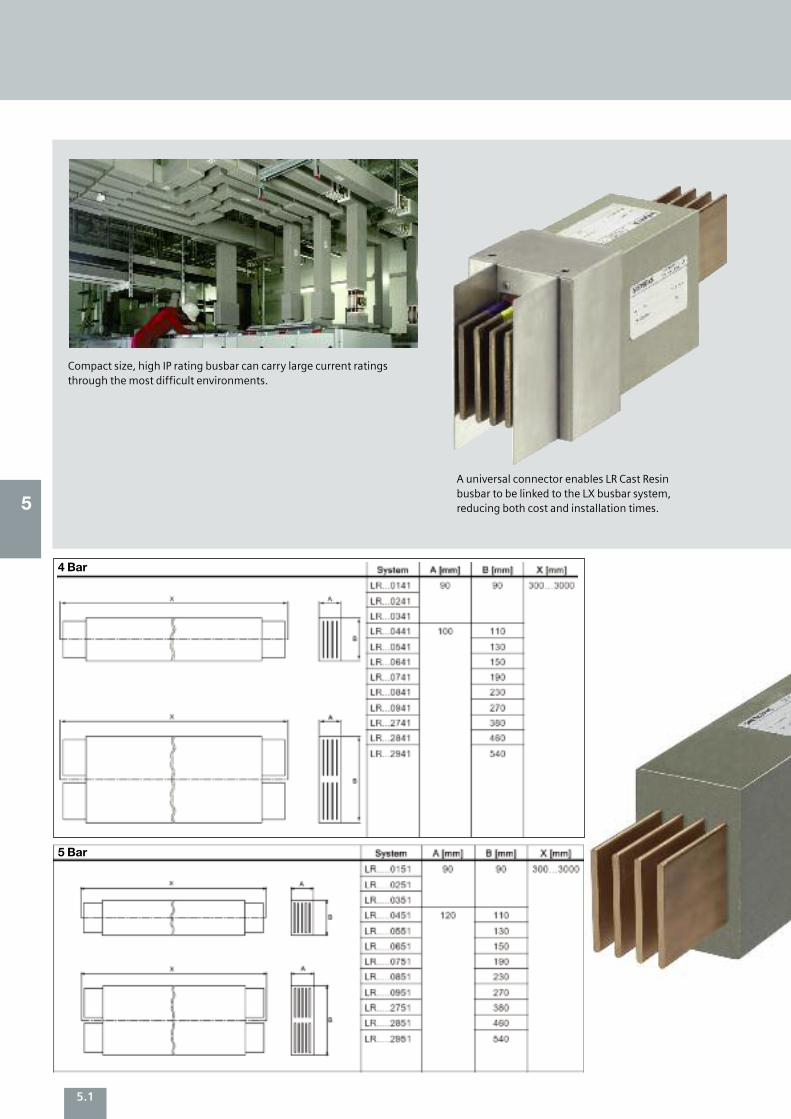
Compact size, high IP rating busbar can carry large current ratingsthrough the most difficult environments.
A universal connector enables LR Cast Resin busbar to be linked to the LX busbar system, reducing both cost and installation times. 5
4 Bar
5 Bar
5.2
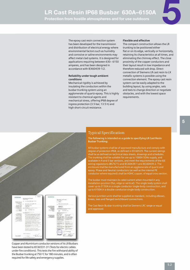
The following is intended as a guide to specifying LR Cast ResinBusbar Trunking:
All busbar systems shall be of approved manufacture and comply withdegree of protection IP68, as defined in IEC60529. The current ratingsshall be as defined on technical data sheets, drawings and schedules. The trunking shall be suitable for use up to 1000V 50Hz supply, andavailable in 4 and 5 bar versions, and meet the requirements of the IEEwiring regulations (BS7671) and IEC60439-1 and IEC60439-2. Theenclosure shall be manufactured from an agglomerate of quartz andepoxy. Phase and Neutral conductors (as well as the internal PEconductor where required) shall be HDHC copper, of equal cross section.
The busbar must maintain its rated current when mounted in anyinstallation position (flat, edge or vertical). The single body system shallcover up to 3150A in a single-conductor single-body construction, andup to 6150A in a double-conductor single-body construction.
Various junction units shall be supplied as standard, including elbows,knees, tees and flanged switchboard connections.
The Cast Resin Busbar trunking shall be Siemens LRC range or equal and approved.
Typical Specification
The epoxy cast resin connection systemhas been developed for the transmissionand distribution of electrical energy whereenvironmental factors such as humidityand corrosive or saline environments mayaffect metal clad systems. It is designed forapplications requiring between 630– 6150amperes, and has been designed inaccordance with IEX60439-1/2.
Reliability under tough ambientconditions Mechanical rigidity is achieved byinsulating the conductors within thebusbar trunking system using anagglomerate of quartz-epoxy. This is highlyresistant to chemical agents andmechanical stress, offering IP68 degree ofingress protection (3.5 bar, 13.5 h) andhigh short-circuit resistance.
Flexible and effectiveThe compact construction allows the LRtrunking to be positioned either flat or on its edge, vertically or horizontally,retaining its characteristics at all times, andeliminating the chimney effect. The closeproximity of the copper conductors andtheir layout result in low impedance andtherefore reduced volt drop. Directconnection of Siemens LR cast resin to LXmetallic systems is possible using theconnection element. The epoxy cast resinsystem can be easily adapted to thebuilding layout, by using angles, sets and tees to change direction or negotiate obstacles, and with the lowest space requirements.
Copper and Aluminium conductor versions of its LR Busbarshave been tested to IEC60331-31 (Tests for electric cablesunder fire conditions). This tests the fire withstand ability ofthe Busbar trunking at 750 oC for 180 minutes, and is oftenrequired for life safety and emergency supplies.
5
5LR Cast Resin IP68 Busbar 630A–6150AProtection from hostile atmospheres and for use outdoors
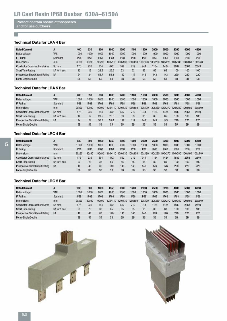
5.3
Protection from hostile atmospheres and for use outdoors
LR Cast Resin IP68 Busbar 630A–6150A
Technical Data for LRA 4 Bar
Rated Current A 400 630 800 1000 1200 1400 1600 2000 2500 3200 4000 4600
Rated Voltage VAC 1000 1000 1000 1000 1000 1000 1000 1000 1000 1000 1000 1000
IP Rating Standard IP68 IP68 IP68 IP68 IP68 IP68 IP68 IP68 IP68 IP68 IP68 IP68
Dimensions mm 90x90 90x90 90x90 100x110 100x130 100x150 100x190 100x230 100x270 100x380 100x460 100x540
Conductor Cross-sectional Area Sq mm 176 236 354 472 592 712 944 1184 1424 1889 2368 2849
Short Time Rating kA for 1 sec 12 12 26.5 26.6 53 53 65 65 65 100 100 100
Prospective Short Circuit Rating kA 24 24 55.7 55.8 117 117 143 143 143 220 220 220
Form-Single/Double SB SB SB SB SB SB SB SB SB SB SB SB
Technical Data for LRA 5 Bar
Rated Current A 400 630 800 1000 1200 1400 1600 2000 2500 3200 4000 4600
Rated Voltage VAC 1000 1000 1000 1000 1000 1000 1000 1000 1000 1000 1000 1000
IP Rating Standard IP68 IP68 IP68 IP68 IP68 IP68 IP68 IP68 IP68 IP68 IP68 IP68
Dimensions mm 90x90 90x90 90x90 120x110 120x130 120x150 120x190 120x230 120x270 120x380 120x460 120x540
Conductor Cross-sectional Area Sq mm 176 236 354 472 592 712 944 1184 1424 1889 2368 2849
Short Time Rating kA for 1 sec 12 12 26.5 26.6 53 53 65 65 65 100 100 100
Prospective Short Circuit Rating kA 24 24 55.7 55.8 117 117 143 143 143 220 220 220
Form-Single/Double SB SB SB SB SB SB SB SB SB SB SB SB
Technical Data for LRC 4 Bar
Rated Current A 630 800 1000 1350 1600 1700 2000 2500 3200 4000 5000 6150
Rated Voltage VAC 1000 1000 1000 1000 1000 1000 1000 1000 1000 1000 1000 1000
IP Rating Standard IP68 IP68 IP68 IP68 IP68 IP68 IP68 IP68 IP68 IP68 IP68 IP68
Dimensions mm 90x90 90x90 90x90 100x110 100x130 100x150 100x190 100x230 100x270 100x380 100x460 100x540
Conductor Cross-sectional Area Sq mm 176 236 354 472 592 712 944 1184 1424 1889 2368 2849
Short Time Rating kA for 1 sec 23 23 38 65 65 65 65 80 80 100 100 100
Prospective Short Circuit Rating kA 48 48 80 140 140 140 140 176 176 220 220 220
Form-Single/Double SB SB SB SB SB SB SB SB SB SB SB SB
Technical Data for LRC 5 Bar
Rated Current A 630 800 1000 1350 1600 1700 2000 2500 3200 4000 5000 6150
Rated Voltage VAC 1000 1000 1000 1000 1000 1000 1000 1000 1000 1000 1000 1000
IP Rating Standard IP68 IP68 IP68 IP68 IP68 IP68 IP68 IP68 IP68 IP68 IP68 IP68
Dimensions mm 90x90 90x90 90x90 120x110 120x130 120x150 120x190 120x230 120x270 120x380 120x460 120x540
Conductor Cross-sectional Area Sq mm 176 236 354 472 592 712 944 1184 1424 1889 2368 2849
Short Time Rating kA for 1 sec 23 23 38 65 65 65 65 80 80 100 100 100
Prospective Short Circuit Rating kA 48 48 80 140 140 140 140 176 176 220 220 220
Form-Single/Double SB SB SB SB SB SB SB SB SB SB SB SB
5
6Power Track Underfloor Busbar System
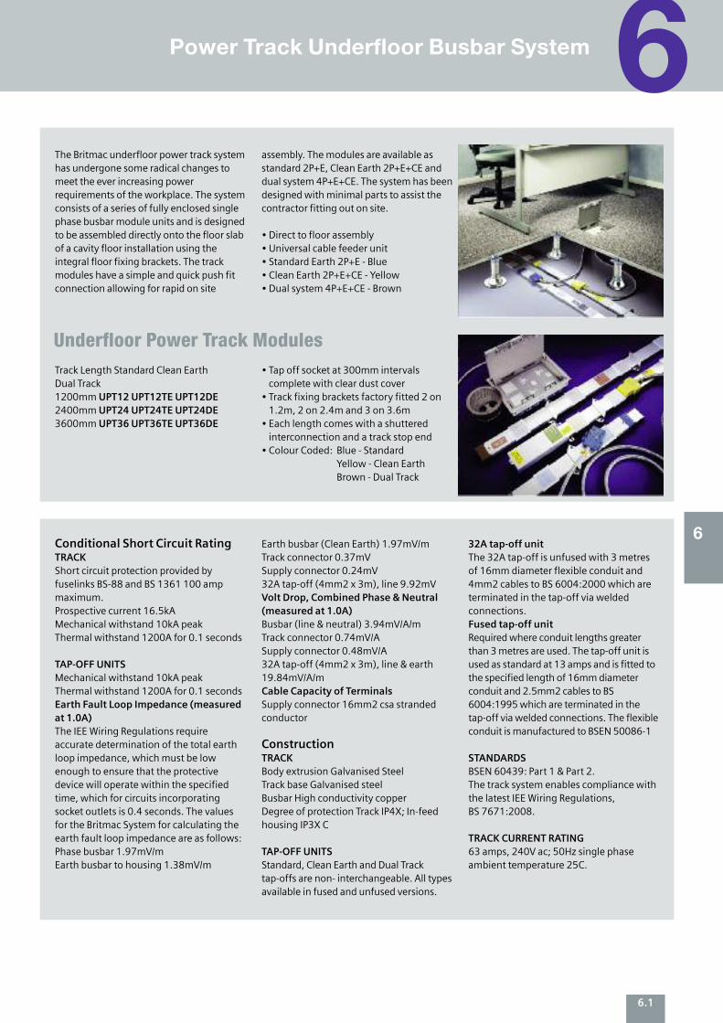
The Britmac underfloor power track systemhas undergone some radical changes tomeet the ever increasing powerrequirements of the workplace. The systemconsists of a series of fully enclosed singlephase busbar module units and is designedto be assembled directly onto the floor slabof a cavity floor installation using theintegral floor fixing brackets. The trackmodules have a simple and quick push fitconnection allowing for rapid on site
assembly. The modules are available asstandard 2P+E, Clean Earth 2P+E+CE anddual system 4P+E+CE. The system has beendesigned with minimal parts to assist thecontractor fitting out on site.
• Direct to floor assembly• Universal cable feeder unit• Standard Earth 2P+E - Blue• Clean Earth 2P+E+CE - Yellow• Dual system 4P+E+CE - Brown
Track Length Standard Clean Earth Dual Track1200mm UPT12 UPT12TE UPT12DE2400mm UPT24 UPT24TE UPT24DE3600mm UPT36 UPT36TE UPT36DE
• Tap off socket at 300mm intervalscomplete with clear dust cover
• Track fixing brackets factory fitted 2 on1.2m, 2 on 2.4m and 3 on 3.6m
• Each length comes with a shutteredinterconnection and a track stop end
• Colour Coded: Blue - StandardYellow - Clean EarthBrown - Dual Track
Underfloor Power Track Modules
Conditional Short Circuit RatingTRACKShort circuit protection provided byfuselinks BS-88 and BS 1361 100 ampmaximum.Prospective current 16.5kAMechanical withstand 10kA peakThermal withstand 1200A for 0.1 seconds
TAP-OFF UNITSMechanical withstand 10kA peakThermal withstand 1200A for 0.1 secondsEarth Fault Loop Impedance (measured at 1.0A)The IEE Wiring Regulations requireaccurate determination of the total earthloop impedance, which must be lowenough to ensure that the protectivedevice will operate within the specifiedtime, which for circuits incorporatingsocket outlets is 0.4 seconds. The valuesfor the Britmac System for calculating theearth fault loop impedance are as follows:Phase busbar 1.97mV/mEarth busbar to housing 1.38mV/m
Earth busbar (Clean Earth) 1.97mV/mTrack connector 0.37mVSupply connector 0.24mV32A tap-off (4mm2 x 3m), line 9.92mVVolt Drop, Combined Phase & Neutral(measured at 1.0A)Busbar (line & neutral) 3.94mV/A/mTrack connector 0.74mV/ASupply connector 0.48mV/A32A tap-off (4mm2 x 3m), line & earth19.84mV/A/mCable Capacity of TerminalsSupply connector 16mm2 csa strandedconductor
ConstructionTRACKBody extrusion Galvanised SteelTrack base Galvanised steelBusbar High conductivity copperDegree of protection Track IP4X; In-feedhousing IP3X C
TAP-OFF UNITSStandard, Clean Earth and Dual Tracktap-offs are non- interchangeable. All typesavailable in fused and unfused versions.
32A tap-off unitThe 32A tap-off is unfused with 3 metresof 16mm diameter flexible conduit and4mm2 cables to BS 6004:2000 which areterminated in the tap-off via weldedconnections.Fused tap-off unitRequired where conduit lengths greaterthan 3 metres are used. The tap-off unit isused as standard at 13 amps and is fitted tothe specified length of 16mm diameterconduit and 2.5mm2 cables to BS6004:1995 which are terminated in thetap-off via welded connections. The flexibleconduit is manufactured to BSEN 50086-1
STANDARDSBSEN 60439: Part 1 & Part 2.The track system enables compliance withthe latest IEE Wiring Regulations,BS 7671:2008.
TRACK CURRENT RATING63 amps, 240V ac; 50Hz single phaseambient temperature 25C.
6
6.1
6.2
Underfloor floor box distribution
OverviewPower Track Underfloor Busbar System
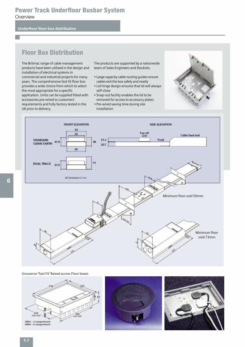
Floor Box Distribution
6
Minimum floor void 50mm
Minimum floor void 73mm
Grosvenor ‘Fast Fit’ Raised access Floor boxes
The Britmac range of cable managementproducts have been utilised in the design andinstallation of electrical systems incommercial and industrial projects for manyyears. The comprehensive fast-fit floor boxprovides a wide choice from which to selectthe most appropriate for a specificapplication. Units can be supplied fitted withaccessories pre-wired to customers’requirements and fully factory tested in theUK prior to delivery.
The products are supported by a nationwideteam of Sales Engineers and Stockists.
• Large capacity cable routing guides ensurecables exit the box safely and neatly
• Lid hinge design ensures that lid will alwaysself-close
• Snap-out facility enables the lid to beremoved for access to accessory plates
• Pre-wired saving time during siteinstallation

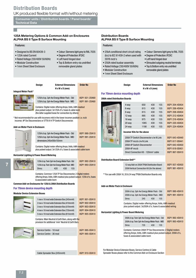
Features:
• Complies with BS EN 60439-3• 16kA Conditional fault rating• Rated Voltage 230V 50/60Hz• Incomer(s) provided as standard• Modular Construction• Top, bottom, side & rear entry• Colour: Siemens light grey to RAL 7035
• Degree of Protection: IP2XC• Comb busbar system• Earth & Neutral Bars supplied asstandard
• Full DIN rail supplied as standard• User defined Split load units
7ALPHA BS II Type B TP&N Distribution Boards
7
7.1
For 70mm device mounting depth
Consumer UnitsALPHA BS I All Insulated & Metalclad Surface Mounting
Distribution BoardsALPHA BS II Type B Surface Mounting
Design External Dimensions Order No
H x W x D (mm)
All insulated
Main Switch All Insulated Consumer Units with 100A Incomer
5 way 230 190 120
8 way 230 243 120
11 way 230 294 120
14 way 230 344 120
19 way 230 439 120
8GB1 335-1DA
8GB1 335-2DA
8GB1 335-3DA
8GB1 335-4DA
8GB1 335-5DA
Metal Clad
Main Switch Metalclad Consumer Units with 100A Incomer
5 way 210 188 122
8 way 210 242 122
11 way 210 292 122
14 way 210 343 122
19 way 210 439 122
8GB3 335-1DA
8GB3 335-2DA
8GB3 335-3DA
8GB3 335-4DA
8GB3 335-5DA
User defined Split Load Metalclad Consumer Unit with 100A
Main Switch incomer and 80A 30mA rccb
9 way 210 292 122
12 way 210 343 122
17 way* 210 439 122
*** For use with 125A 16, 20 & 24 way TP&N Distribution Boards only
* Requires 8GP1 853--0DA20 single phase connection kit** Requires 8GP1 886--0DA10 4P connection kit*** For use with 125A 16, 20 and 24 way TP&N Distribution boards only
Accessoriesmcb blanking plate
A minimum of 5 outgoing ways isrecommended on the main switch circuit
A minimum of 5 outgoing ways isrecommended on the main switch circuit
8GB3 335-6DA
8GB3 335-7DA
8GB3 335-8DA
8GP1 994-0DA10
User defined Split Load All Insulated Consumer Unit with 100A
Main Switch incomer and 80A 30mA rccb
9 way 230 294 120
12 way 230 344 120
17 way* 230 439 120
8GB1 335-6DA
8GB1 335-7DA
8GB1 335-8DA
Features:
• Type Tested to BS EN 60439-3• 10kA for 0.1 second fault rated• 125A rated Current• Rated Voltage 230/400V 50/60Hz• Modular Construction• 1mm Sheet Steel Enclosure
• Colour: Siemens light grey to RAL 7035• Degree of Protection: IP2XC• Left hand hinged door• Shrouded outgoing neutral terminals• Top & Bottom entry via undrilledremovable gland plates
For 70mm device mounting depth
Design External Dimensions Order No
H x W x D (mm)
125A rated Distribution Boards
4 way 490 430 155
6 way 570 430 155
8 way 650 430 155
12 way 815 430 155
16 way 895 430 155
20 way 975 430 155
24 way 1140 430 155
8GP1 204-2DA54
8GP1 206-2DA54
8GP1 208-2DA54
8GP1 212-2DA54
8GP1 216-2DA54
8GP1 220-2DA54
8GP1 224-2DA54
Incomer Options & Kits for the above
100A DP Switch Disconnector *
100A TP Switch Disconnector
100A 4P Switch Disconnector *
125A DP Switch Disconnector
125A TP Switch Disconnector **
125A 4P Switch Disconnector
125A 4P 30mA rccb **
125A 4P 300mA rccb **
Direct Connection Kit - 50mm² cable
Direct Connection Kit - 120mm² cable
Outgoing Direct Connection Kit - 50mm² cable
5TE1 201-0DA
5TE1 301-0DA
5TE1 401-0DA
5TE1 202-0DA
5TE1 302-0DA
5TE1 402-0DA
5SM3 345-0
5SM3 645-0
8GP1 854-0DA10
8GP1 856-0DA10
8GP1 855-0DA10
Conversion/Connection Kits
125A TP to SP Conversion Kit
4P rccb Connection Kit
8GP1 853-0DA20
8GP1 886-0DA10
Distribution Board expansion Unit ***
12 way Add-on 125A TP&N Distribution Board
125A Vertical Connection Kit (for the above)
8GP1 937-2DA50
8GP1 981-2DA10
125A rated Distribution Boards with Integral DIN Rail
4 way 650 430 155
8 way 815 430 155
12 way 975 430 155
16 way 1140 430 155
20 way 1140 430 155
8GP1 104-2DA50
8GP1 108-2DA50
8GP1 112-2DA50
8GP1 116-2DA50
8GP1 120-2DA50
7
7.2
Features:
• Designed to BS EN 60439-3• 125A rated Current• Rated Voltage 230/400V 50/60Hz• Modular Construction• 1mm Sheet Steel Enclosure
• Colour: Siemens light grey to RAL 7035• Degree of Protection: IP2XC• Left hand hinged door• Top & Bottom entry via undrilledremovable gland plates
125A Metering Options & Common Add-on EnclosuresALPHA BS II Type B Surface Mounting
Distribution BoardsALPHA BS II Type B Surface Mounting
Design External Dimensions Order No
H x W x D (mm)
Integral Meter Pack*
125A ct op. 3ph 4w Energy Meter Pack - Std
125A ct op. 3ph 4w Energy Meter Pack - MID
8GP1 921-2DA80
8GP1 991-2DA80
Horizontal Lighting & Power Board Metering
Common Add-on Enclosures for 125A & 200A Distribution Boards
125A ct op. Twin 3ph 4w Energy Meter Pack -Std
125A ct op. Twin 3ph 4w Energy Meter Pack -MID
Dims: 420 430 155
8GP1 992-2DA10
8GP1 993-2DA10
Modular Device Extension Boxes
1 row x 18 mod wide Extension Box (245mmH)
2 row x 18 mod wide Extension Box (410mmH)
3 row x 18 mod wide Extension Box (570mmH)
4 row x 18 mod wide Extension Box (735mmH)
5 row x 18 mod wide Extension Box (815mmH)
** For use with 200A 16, 20 & 24 way TP&N Distribution Boards only
Contains: Digital meter offering Amps, Volts, kWh readoutplus pulsed output. 3x125A ct's, fuses & cable loom(the latter supplied loose for connection by others)
Contains: Common 125A TP Sw Disconnector, 2 Digital metersoffering Amps, Volts, kWh readout plus pulsed output. 125A ct's, fuses& associated cable loom
Contains: Main Neutral & Earth Bars, along with theprovision for additional 'mini' Neutral & Earth Bars.
* Not recommended for use with incomers mtd in the lower incomer position i.e. rccbincomer, 4P Sw Disconnectors or 5TT8 814 TP Switch Disconnector.
Add-on Meter Pack in Enclosure
125A ct op. 3ph 4w Energy Meter Pack - Std
125A ct op. 3ph 4w Energy Meter Pack - MID
dimensions 245x430x155mm
8GP1 990-2DA10
8GP1 991-2DA10
Contains: Digital meter offering Amps, Volts, kWh readoutplus pulsed output. 3x125A ct's, fuses & associated cable loom
8GP1 901-0DA10
8GP1 902-0DA10
8GP1 903-0DA10
8GP1 904-0DA10
8GP1 905-0DA10
Features:
• 25kA conditional short circuit rating(Icc) to IEC 61439-2 when used with5SY8 mcb's
• 250A rated busbar assembly• Rated Voltage 230/400V 50/60Hz• Modular Construction• 1mm Sheet Steel Enclosure
• Colour: Siemens light grey to RAL 7035• Degree of Protection: IP2XC• Left hand hinged door• Shrouded outgoing neutral terminals• Top & Bottom entry via undrilledremovable gland plates
For 70mm device mounting depth
Design External Dimensions Order No
H x W x D (mm)
200A rated Distribution Boards
4 way 650 430 155
6 way 815 430 155
8 way 815 430 155
12 way 895 430 155
16 way 975 430 155
20 way 1085 430 155
24 way 1190 430 155
8GP1 204-4DA54
8GP1 206-4DA54
8GP1 208-4DA54
8GP1 212-4DA54
8GP1 216-4DA54
8GP1 220-4DA54
8GP1 224-4DA54
Service Centre - 18 mod
Service Centre - 36 mod
8GP1 995-0DA13
8GP1 995-0DA14
Cable Spreader Box (245mmH) 8GP1 910-0DA10
Distribution Board Extension Unit**
12 way Add-on 200A TP&N Distribution Board
200A Vertical Connection Kit (for the above)
8GP1 937-4DA50
8GP1 981-4DA10
Contains: Digital meter offering Amps, Volts, kWh readoutplus pulsed output. 3x200A ct's, fuses & associated wiring
Add-on Meter Pack in Enclosure
200A ct op. 3ph 4w Energy Meter Pack - Std
200A ct op. 3ph 4w Energy Meter Pack - MID
Dims: 245 430 155
8GP1 990-4DA10
8GP1 991-4DA10
Contains: Common 200A TP Sw Disconnector, 2 Digital metersoffering Amps, Volts, kWh readout plus pulsed output. 200A ct's,fuses & associated cable loom
For Modular Device Extension Boxes, Service Centres & CableSpreader Boxes please refer to the Common Add-on Enclosure Section
Horizontal Lighting & Power Board Metering
200A ct op. Twin 3ph 4w Energy Meter Pack - Std
200A ct op. Twin 3ph 4w Energy Meter Pack - MID
Dims: 735 430 155
8GP1 992-4DA10
8GP1 993-4DA10
Incomer Kits for the above
200A TP Switch Disconnector c/w N Link
200A TP mccb c/w N Link
200A 4P Switch Disconnector
200A 4P mccb
Direct Connection Kit - 120mm2 cable
8GP1 643-4DA40
8GP1 617-0DA41
8GP1 643-4DA50
8GP1 618-0DA51
8GP1 867-0DA10
Consumer units / Distribution boards / Panel boards'Technical Data
UK produced flexible format with/without meteringDistribution Boards
For 70mm device mounting depth
7
7.3
Features:
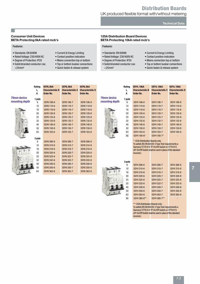
• Standards: EN 60898• Rated Voltage: 230/400V AC• Degree of Protection: IP20• Solid/stranded conductor csa:<25mm²
• Current & Energy Limiting• Contact position indication• Mains connection top or bottom• Top or bottom busbar connections• Quick fasten & release system
70mm device mounting depth
Consumer Unit DevicesBETA Protecting 6kA rated mcb's
Rating 5SY6, 6kA 5SY6, 6kA 5SY6, 6kA
In Characteristic B Characteristic C Characteristic D
A Order No. Order No. Order No.
1 pole
5SY6 106-6
5SY6 110-6
5SY6 116-6
5SY6 120-6
5SY6 125-6
5SY6 132-6
5SY6 140-6
5SY6 150-6
5SY6 163-6
6
10
16
20
25
32
40
50
63
5SY6 106-7
5SY6 110-7
5SY6 116-7
5SY6 120-7
5SY6 125-7
5SY6 132-7
5SY6 140-7
5SY6 150-7
5SY6 163-7
5SY6 106-8
5SY6 110-8
5SY6 116-8
5SY6 120-8
5SY6 125-8
5SY6 132-8
5SY6 140-8
5SY6 150-8
5SY6 163-8
3 pole
5SY6 306-6
5SY6 310-6
5SY6 316-6
5SY6 320-6
5SY6 325-6
5SY6 332-6
5SY6 340-6
5SY6 350-6
5SY6 363-6
6
10
16
20
25
32
40
50
63
5SY6 306-7
5SY6 310-7
5SY6 316-7
5SY6 320-7
5SY6 325-7
5SY6 332-7
5SY6 340-7
5SY6 350-7
5SY6 363-7
5SY6 306-8
5SY6 310-8
5SY6 316-8
5SY6 320-8
5SY6 325-8
5SY6 332-8
5SY6 340-8
5SY6 350-8
5SY6 363-8
Features:
• Standards: EN 60898• Rated Voltage: 230/400V AC• Degree of Protection: IP20• Solid/stranded conductor csa:<25mm²
• Current & Energy Limiting• Contact position indication• Mains connection top or bottom• Top or bottom busbar connections• Quick fasten & release system
70mm device mounting depth
125A Distribution Board DevicesBETA Protecting 10kA rated mcb's
Rating 5SY4, 10kA 5SY4, 10kA 5SY4, 10kA
In Characteristic B Characteristic C Characteristic D
A Order No. Order No. Order No.
1 pole
5SY4 106-6
5SY4 110-6
5SY4 116-6
5SY4 120-6
5SY4 125-6
5SY4 132-6
5SY4 140-6
5SY4 150-6
5SY4 163-6
5SY4 180-6*
6
10
16
20
25
32
40
50
63
80
5SY4 106-7
5SY4 110-7
5SY4 116-7
5SY4 120-7
5SY4 125-7
5SY4 132-7
5SY4 140-7
5SY4 150-7
5SY4 163-7
5SY4 180-7*
5SY4 106-8
5SY4 110-8
5SY4 116-8
5SY4 120-8
5SY4 125-8
5SY4 132-8
5SY4 140-8
5SY4 150-8
5SY4 163-8
-
3 pole
5SY4 306-6
5SY4 310-6
5SY4 316-6
5SY4 320-6
5SY4 325-6
5SY4 332-6
5SY4 340-6
5SY4 350-6
5SY4 363-6
5SY4 380-6**
6
10
16
20
25
32
40
50
63
80
5SY4 306-7
5SY4 310-7
5SY4 316-7
5SY4 320-7
5SY4 325-7
5SY4 332-7
5SY4 340-7
5SY4 350-7
5SY4 363-7
5SY4 380-7**
5SY4 306-8
5SY4 310-8
5SY4 316-8
5SY4 320-8
5SY4 325-8
5SY4 332-8
5SY4 340-8
5SY4 350-8
5SY4 363-8
-
* 125A Distribution Boards only:To satisfy BS EN 60439-3 Type Test requirements aSiemens 5TT8 814 TP On/Off Switch or 5TT8 815 (4P On/Off Switch shall be used in place of the standardincomer.)
** 125A Distribution Boards only:To satisfy BS EN 60439-3 Type Test requirements aSiemens 5TT8 814 TP On/Off Switch or 5TT8 815 (4P On/Off Switch shall be used in place of the standardincomer.)
Technical Data
UK produced flexible format with/without meteringDistribution Boards
7.4
7
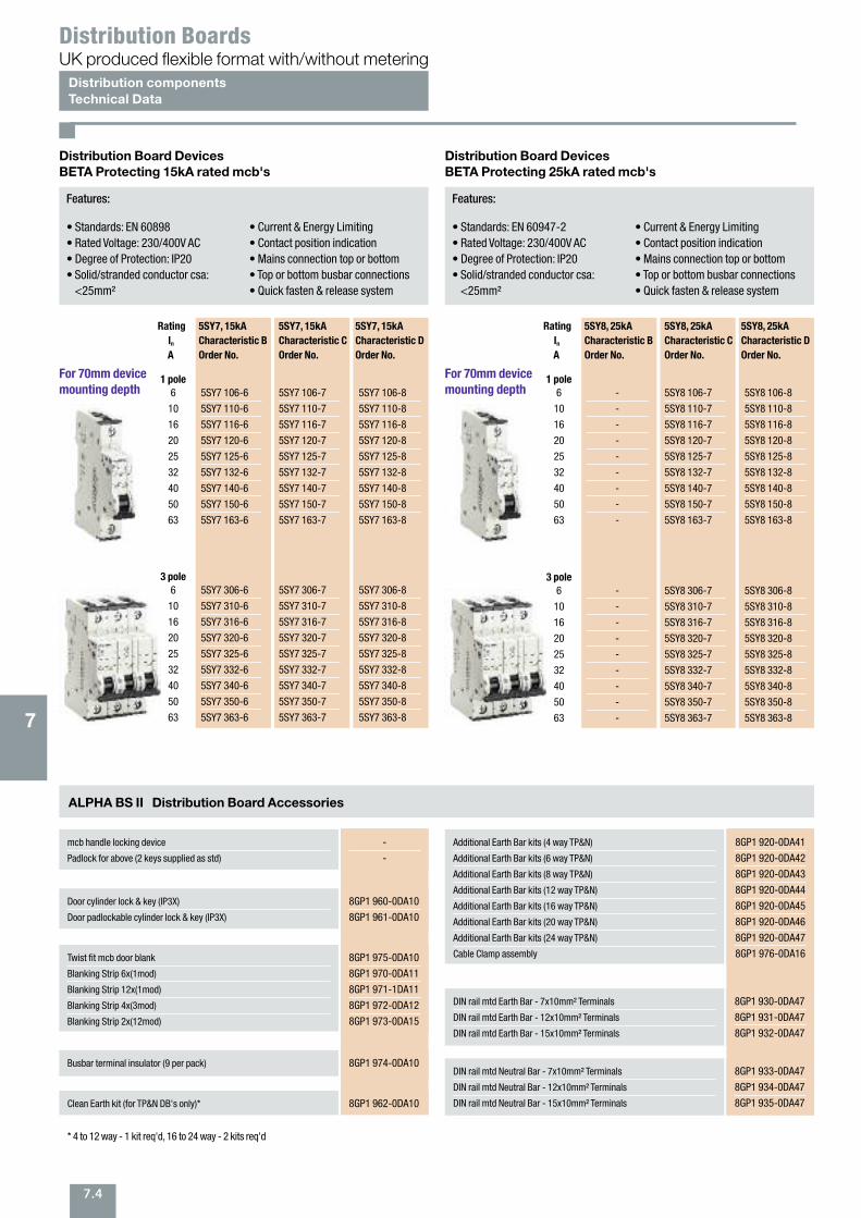
Features:
• Standards: EN 60898• Rated Voltage: 230/400V AC• Degree of Protection: IP20• Solid/stranded conductor csa:<25mm²
• Current & Energy Limiting• Contact position indication• Mains connection top or bottom• Top or bottom busbar connections• Quick fasten & release system
For 70mm device mounting depth
Distribution Board DevicesBETA Protecting 15kA rated mcb's
ALPHA BS II Distribution Board Accessories
Rating 5SY7, 15kA 5SY7, 15kA 5SY7, 15kA
In Characteristic B Characteristic C Characteristic D
A Order No. Order No. Order No.
1 pole
5SY7 106-6
5SY7 110-6
5SY7 116-6
5SY7 120-6
5SY7 125-6
5SY7 132-6
5SY7 140-6
5SY7 150-6
5SY7 163-6
6
10
16
20
25
32
40
50
63
5SY7 106-7
5SY7 110-7
5SY7 116-7
5SY7 120-7
5SY7 125-7
5SY7 132-7
5SY7 140-7
5SY7 150-7
5SY7 163-7
5SY7 106-8
5SY7 110-8
5SY7 116-8
5SY7 120-8
5SY7 125-8
5SY7 132-8
5SY7 140-8
5SY7 150-8
5SY7 163-8
3 pole
5SY7 306-6
5SY7 310-6
5SY7 316-6
5SY7 320-6
5SY7 325-6
5SY7 332-6
5SY7 340-6
5SY7 350-6
5SY7 363-6
6
10
16
20
25
32
40
50
63
5SY7 306-7
5SY7 310-7
5SY7 316-7
5SY7 320-7
5SY7 325-7
5SY7 332-7
5SY7 340-7
5SY7 350-7
5SY7 363-7
5SY7 306-8
5SY7 310-8
5SY7 316-8
5SY7 320-8
5SY7 325-8
5SY7 332-8
5SY7 340-8
5SY7 350-8
5SY7 363-8
Features:
• Standards: EN 60947-2• Rated Voltage: 230/400V AC• Degree of Protection: IP20• Solid/stranded conductor csa:<25mm²
• Current & Energy Limiting• Contact position indication• Mains connection top or bottom• Top or bottom busbar connections• Quick fasten & release system
For 70mm device mounting depth
Distribution Board DevicesBETA Protecting 25kA rated mcb's
Rating 5SY8, 25kA 5SY8, 25kA 5SY8, 25kA
In Characteristic B Characteristic C Characteristic D
A Order No. Order No. Order No.
1 pole
-
-
-
-
-
-
-
-
-
6
10
16
20
25
32
40
50
63
5SY8 106-7
5SY8 110-7
5SY8 116-7
5SY8 120-7
5SY8 125-7
5SY8 132-7
5SY8 140-7
5SY8 150-7
5SY8 163-7
5SY8 106-8
5SY8 110-8
5SY8 116-8
5SY8 120-8
5SY8 125-8
5SY8 132-8
5SY8 140-8
5SY8 150-8
5SY8 163-8
3 pole
-
-
-
-
-
-
-
-
-
6
10
16
20
25
32
40
50
63
5SY8 306-7
5SY8 310-7
5SY8 316-7
5SY8 320-7
5SY8 325-7
5SY8 332-7
5SY8 340-7
5SY8 350-7
5SY8 363-7
5SY8 306-8
5SY8 310-8
5SY8 316-8
5SY8 320-8
5SY8 325-8
5SY8 332-8
5SY8 340-8
5SY8 350-8
5SY8 363-8
Distribution componentsTechnical Data
UK produced flexible format with/without meteringDistribution Boards
mcb handle locking device
Padlock for above (2 keys supplied as std)
-
-
Door cylinder lock & key (IP3X)
Door padlockable cylinder lock & key (IP3X)
8GP1 960-0DA10
8GP1 961-0DA10
Clean Earth kit (for TP&N DB's only)* 8GP1 962-0DA10
Busbar terminal insulator (9 per pack) 8GP1 974-0DA10
Twist fit mcb door blank
Blanking Strip 6x(1mod)
Blanking Strip 12x(1mod)
Blanking Strip 4x(3mod)
Blanking Strip 2x(12mod)
8GP1 975-0DA10
8GP1 970-0DA11
8GP1 971-1DA11
8GP1 972-0DA12
8GP1 973-0DA15
Additional Earth Bar kits (4 way TP&N)
Additional Earth Bar kits (6 way TP&N)
Additional Earth Bar kits (8 way TP&N)
Additional Earth Bar kits (12 way TP&N)
Additional Earth Bar kits (16 way TP&N)
Additional Earth Bar kits (20 way TP&N)
Additional Earth Bar kits (24 way TP&N)
Cable Clamp assembly
8GP1 920-0DA41
8GP1 920-0DA42
8GP1 920-0DA43
8GP1 920-0DA44
8GP1 920-0DA45
8GP1 920-0DA46
8GP1 920-0DA47
8GP1 976-0DA16
DIN rail mtd Earth Bar - 7x10mm² Terminals
DIN rail mtd Earth Bar - 12x10mm² Terminals
DIN rail mtd Earth Bar - 15x10mm² Terminals
8GP1 930-0DA47
8GP1 931-0DA47
8GP1 932-0DA47
DIN rail mtd Neutral Bar - 7x10mm² Terminals
DIN rail mtd Neutral Bar - 12x10mm² Terminals
DIN rail mtd Neutral Bar - 15x10mm² Terminals
8GP1 933-0DA47
8GP1 934-0DA47
8GP1 935-0DA47
* 4 to 12 way - 1 kit req'd, 16 to 24 way - 2 kits req'd
7.5
7
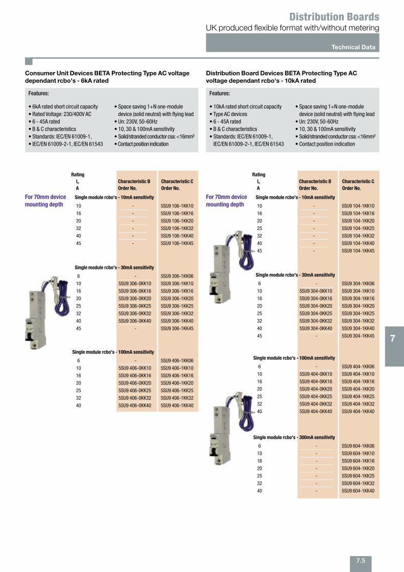
Features:
• 6kA rated short circuit capacity• Rated Voltage: 230/400V AC• 6 - 45A rated• B & C characteristics• Standards: IEC/EN 61009-1,• IEC/EN 61009-2-1, IEC/EN 61543
• Space saving 1+N one-moduledevice (solid neutral) with flying lead
• Un: 230V, 50-60Hz• 10, 30 & 100mA sensitivity• Solid/stranded conductor csa: <16mm²• Contact position indication
For 70mm device mounting depth
Consumer Unit Devices BETA Protecting Type AC voltagedependant rcbo's - 6kA rated
Rating
In Characteristic B Characteristic C
A Order No. Order No.
Single module rcbo's - 10mA sensitivity
10
16
20
32
40
45
-
-
-
-
-
-
5SU9 106-1KK10
5SU9 106-1KK16
5SU9 106-1KK20
5SU9 106-1KK32
5SU9 106-1KK40
5SU9 106-1KK45
Single module rcbo's - 30mA sensitivity
6
10
16
20
25
32
40
45
-
5SU9 306-0KK10
5SU9 306-0KK16
5SU9 306-0KK20
5SU9 306-0KK25
5SU9 306-0KK32
5SU9 306-0KK40
-
5SU9 306-1KK06
5SU9 306-1KK10
5SU9 306-1KK16
5SU9 306-1KK20
5SU9 306-1KK25
5SU9 306-1KK32
5SU9 306-1KK40
5SU9 306-1KK45
Single module rcbo's - 100mA sensitivity
6
10
16
20
25
32
40
-
5SU9 406-0KK10
5SU9 406-0KK16
5SU9 406-0KK20
5SU9 406-0KK25
5SU9 406-0KK32
5SU9 406-0KK40
5SU9 406-1KK06
5SU9 406-1KK10
5SU9 406-1KK16
5SU9 406-1KK20
5SU9 406-1KK25
5SU9 406-1KK32
5SU9 406-1KK40
For 70mm device mounting depth
Rating
In Characteristic B Characteristic C
A Order No. Order No.
Single module rcbo's - 10mA sensitivity
10
16
20
25
32
40
45
-
-
-
-
-
-
-
5SU9 104-1KK10
5SU9 104-1KK16
5SU9 104-1KK20
5SU9 104-1KK25
5SU9 104-1KK32
5SU9 104-1KK40
5SU9 104-1KK45
Single module rcbo's - 30mA sensitivity
6
10
16
20
25
32
40
45
-
5SU9 304-0KK10
5SU9 304-0KK16
5SU9 304-0KK20
5SU9 304-0KK25
5SU9 304-0KK32
5SU9 304-0KK40
-
5SU9 304-1KK06
5SU9 304-1KK10
5SU9 304-1KK16
5SU9 304-1KK20
5SU9 304-1KK25
5SU9 304-1KK32
5SU9 304-1KK40
5SU9 304-1KK45
Single module rcbo's - 100mA sensitivity
6
10
16
20
25
32
40
-
5SU9 404-0KK10
5SU9 404-0KK16
5SU9 404-0KK20
5SU9 404-0KK25
5SU9 404-0KK32
5SU9 404-0KK40
5SU9 404-1KK06
5SU9 404-1KK10
5SU9 404-1KK16
5SU9 404-1KK20
5SU9 404-1KK25
5SU9 404-1KK32
5SU9 404-1KK40
Single module rcbo's - 300mA sensitivity
6
10
16
20
25
32
40
-
-
-
-
-
-
-
5SU9 604-1KK06
5SU9 604-1KK10
5SU9 604-1KK16
5SU9 604-1KK20
5SU9 604-1KK25
5SU9 604-1KK32
5SU9 604-1KK40
Features:
• 10kA rated short circuit capacity• Type AC devices• 6 - 45A rated• B & C characteristics• Standards: IEC/EN 61009-1, IEC/EN 61009-2-1, IEC/EN 61543
• Space saving 1+N one-moduledevice (solid neutral) with flying lead
• Un: 230V, 50-60Hz• 10, 30 & 100mA sensitivity• Solid/stranded conductor csa: <16mm²• Contact position indication
Distribution Board Devices BETA Protecting Type ACvoltage dependant rcbo's - 10kA rated
Technical Data
UK produced flexible format with/without meteringDistribution Boards
8.1
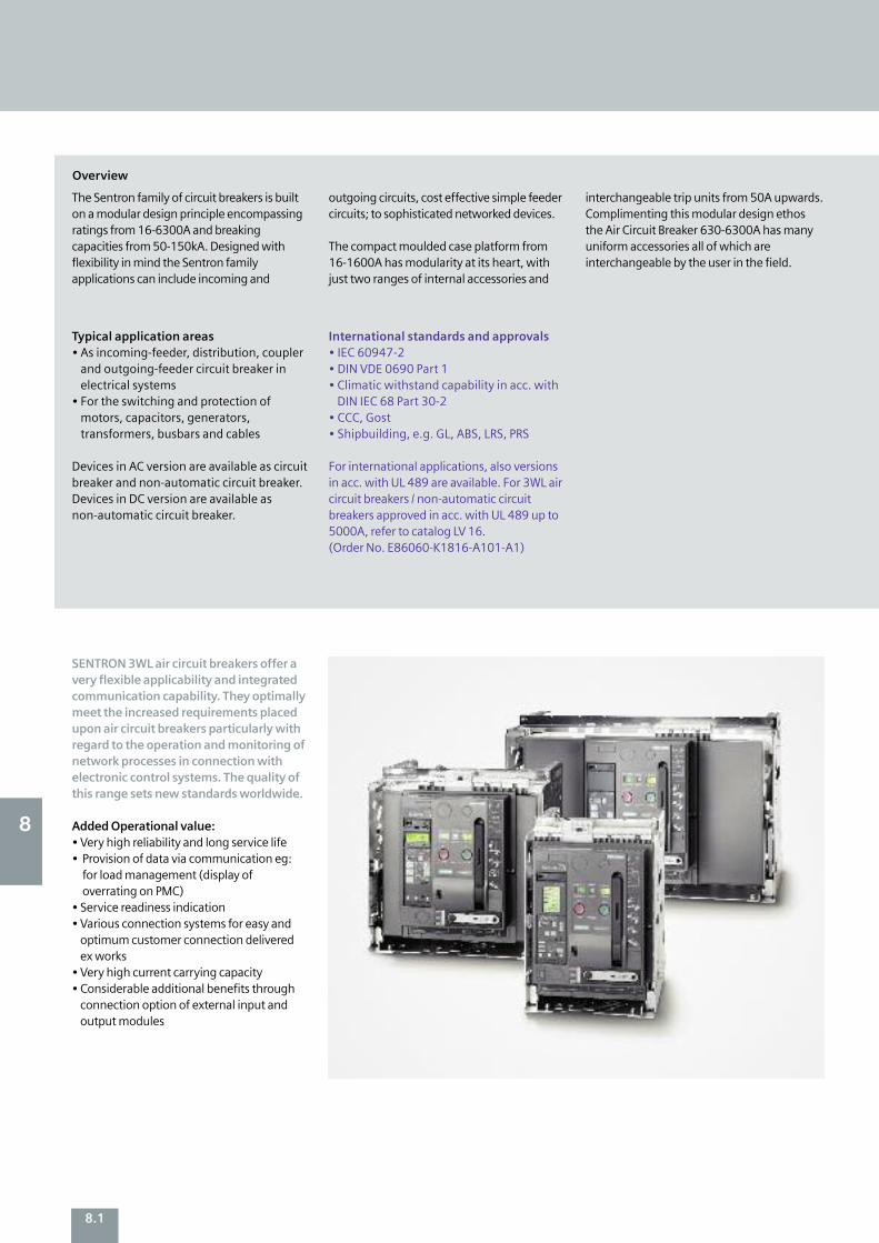
SENTRON 3WL air circuit breakers offer avery flexible applicability and integratedcommunication capability. They optimallymeet the increased requirements placedupon air circuit breakers particularly withregard to the operation and monitoring ofnetwork processes in connection withelectronic control systems. The quality ofthis range sets new standards worldwide.
Added Operational value: • Very high reliability and long service life • Provision of data via communication eg:for load management (display ofoverrating on PMC)
• Service readiness indication • Various connection systems for easy andoptimum customer connection deliveredex works
• Very high current carrying capacity • Considerable additional benefits throughconnection option of external input andoutput modules
The Sentron family of circuit breakers is builton a modular design principle encompassingratings from 16-6300A and breakingcapacities from 50-150kA. Designed withflexibility in mind the Sentron familyapplications can include incoming and
outgoing circuits, cost effective simple feedercircuits; to sophisticated networked devices.
The compact moulded case platform from16-1600A has modularity at its heart, withjust two ranges of internal accessories and
interchangeable trip units from 50A upwards.Complimenting this modular design ethosthe Air Circuit Breaker 630-6300A has manyuniform accessories all of which areinterchangeable by the user in the field.
Typical application areas • As incoming-feeder, distribution, couplerand outgoing-feeder circuit breaker inelectrical systems
• For the switching and protection ofmotors, capacitors, generators,transformers, busbars and cables
Devices in AC version are available as circuitbreaker and non-automatic circuit breaker.Devices in DC version are available asnon-automatic circuit breaker.
International standards and approvals • IEC 60947-2 • DIN VDE 0690 Part 1 • Climatic withstand capability in acc. withDIN IEC 68 Part 30-2
• CCC, Gost • Shipbuilding, e.g. GL, ABS, LRS, PRS
For international applications, also versionsin acc. with UL 489 are available. For 3WL aircircuit breakers / non-automatic circuitbreakers approved in acc. with UL 489 up to5000A, refer to catalog LV 16. (Order No. E86060-K1816-A101-A1)
8
Overview

8.2
3WL air circuit breakers / non-automatic circuit breakers for AC up to 6300A 3WL air circuit breakers for DC up to 4000A Size I, II, III II Rated current In A 630, 800, 1000, 1250, 1000, 2000, 4000
1600, 2000, 2500, 3200, 4000, 5000, 6300
Number of poles 3-pole, 4-pole 3-pole, 4-pole Rated operational V AC up to 690/1150 – voltage Ue V DC – up to 1000 Rated ultimate short- Size I Size II Size III circuit breaking capacity kA 55/66 66/80/100 100/150 (3-pole), 30/25/20 with 415 / 500 V AC 100/130 (4-pole) (with 300/600/1000 V DC)
Type 3WL11 3WL12 3WL13 Size I II III Switching capacity class N S N S H H C C
3-pole 4-pole Short-circuit breaking capacity Rated operational voltage Ue
with 415 / 500 V AC Icu kA 55 66 66 80 100 100 150 130 Ics kA 55 66 66 80 100 100 150 130 Icm kA 121 145 145 176 220 220 330 286 Rated operational voltage Ue with 690 V AC Icu kA 42 50 50 75 85 85 150 130 Icu kA 42 50 50 75 85 85 150 130 Icm kA 88 105 105 165 187 187 330 286 Rated short-time withstand current Icw
of the circuit breakers 0.5 sec kA 55 66 66 80 100 100 100 100 1 sec kA 42 50 55 66 80 100 100 100
Overcurrent releases of SENTRON 3WL circuit breakersType ETU15B ETU25B ETU27B ETU45B ETU76B Overload protection
Short-time delayed short-circuit protection –
Instantaneous short-circuit protection
Neutral conductor protection – –
Ground-fault protection – – • • ZSI – – – • • LCD, 4-line – – – • – LCD, graphical – – – –
Communication via PROFIBUS-DP/Modbus – – – • • Measuring function Plus – – – • • Selectable parameter sets – – – –
Freely programmable parameters – – – –
CubicleBUS – – –
Standard – Not available • Optional
Size I Size II Size III
8
8Sentron Circuit BreakersFlexibly applicable and communication-capable
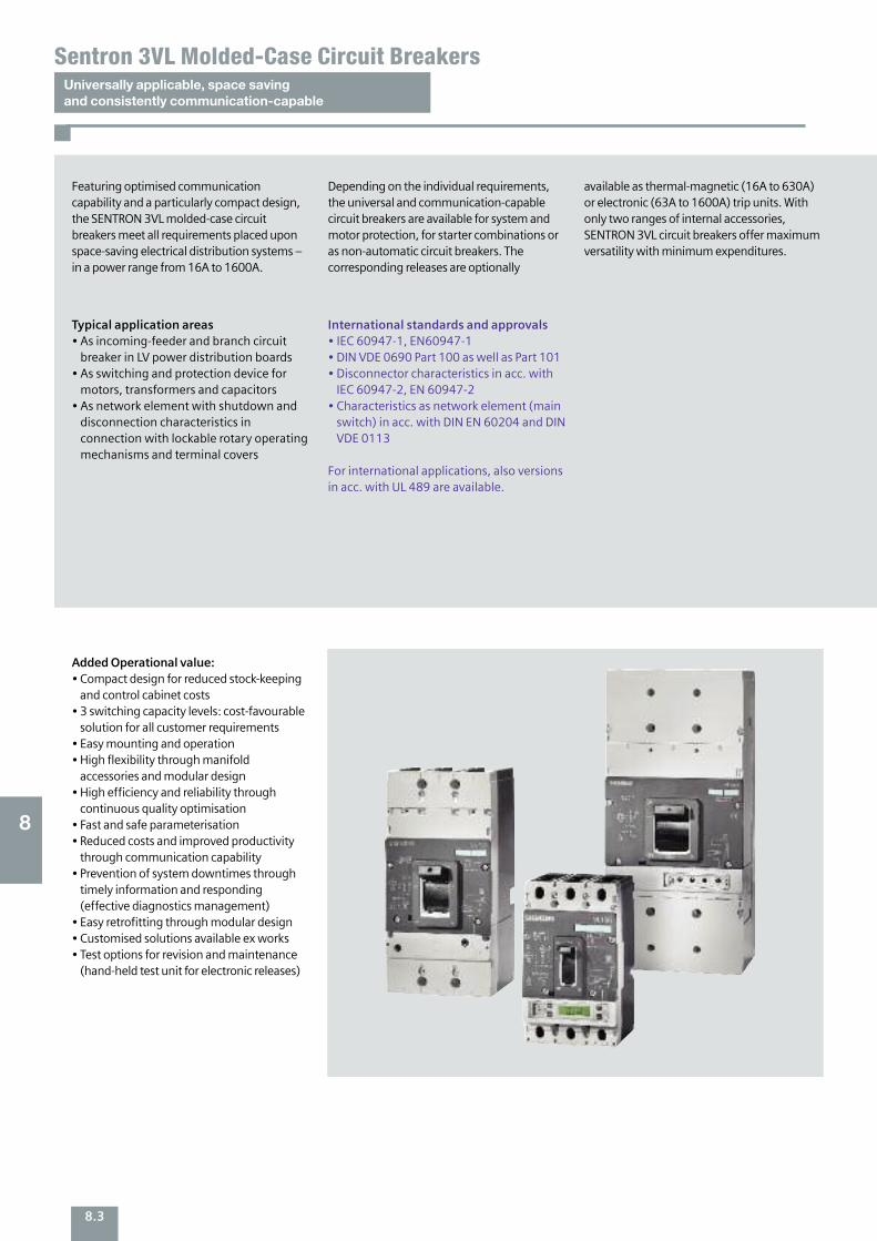
8.3
Universally applicable, space saving and consistently communication-capable
Sentron 3VL Molded-Case Circuit Breakers
Added Operational value: • Compact design for reduced stock-keepingand control cabinet costs
• 3 switching capacity levels: cost-favourablesolution for all customer requirements
• Easy mounting and operation • High flexibility through manifoldaccessories and modular design
• High efficiency and reliability throughcontinuous quality optimisation
• Fast and safe parameterisation • Reduced costs and improved productivitythrough communication capability
• Prevention of system downtimes throughtimely information and responding(effective diagnostics management)
• Easy retrofitting through modular design • Customised solutions available ex works • Test options for revision and maintenance(hand-held test unit for electronic releases)
Featuring optimised communicationcapability and a particularly compact design,the SENTRON 3VL molded-case circuitbreakers meet all requirements placed uponspace-saving electrical distribution systems –in a power range from 16A to 1600A.
Depending on the individual requirements,the universal and communication-capablecircuit breakers are available for system andmotor protection, for starter combinations oras non-automatic circuit breakers. Thecorresponding releases are optionally
available as thermal-magnetic (16A to 630A)or electronic (63A to 1600A) trip units. Withonly two ranges of internal accessories,SENTRON 3VL circuit breakers offer maximumversatility with minimum expenditures.
Typical application areas • As incoming-feeder and branch circuitbreaker in LV power distribution boards
• As switching and protection device formotors, transformers and capacitors
• As network element with shutdown anddisconnection characteristics inconnection with lockable rotary operatingmechanisms and terminal covers
International standards and approvals • IEC 60947-1, EN60947-1 • DIN VDE 0690 Part 100 as well as Part 101 • Disconnector characteristics in acc. withIEC 60947-2, EN 60947-2
• Characteristics as network element (mainswitch) in acc. with DIN EN 60204 and DINVDE 0113
For international applications, also versionsin acc. with UL 489 are available.
8

Type VL160X/3VL1 VL160/3VL2 VL250/3 VL3 VL400 Rated current In A 16 to 160 26 to 160 80 to 250 125 to 400 with 50 °C ambient temperature1)
Rated operational voltage Ue V 690 690 690 690 690 690 690 50/60 Hz AC Overcurrent releases Thermal-magnetic
Electronic ETU LCD –
Replaceable – –
PROFIBUS module COM10 – –
Switching capacity Icu/Icseffective value, in acc. with IEC 60947-2 Standard switching capacity N3)
with 415 V AC kA 55/55 55/55 55/55 55/55 High switching capacity H2)
with 415 V AC kA 70/70 70/70 70/70 70/70 with 690 V AC kA 12/63) 12/6 12/6 15/8 Very high switching capacity L2)
with 415 V AC kA – 100/75 100/75 100/75 with 690 V AC kA – 12/6 12/6 15/8
8.4
Universally applicable, space saving and consistently communication-capable
Sentron 3VL Molded-Case Circuit Breakers
3VL molded-case circuit breakers up to 1600A 3VF2 molded-case circuit breaker up to 100A Type
Type VL630/3VL5 VL800/3VL6 VL1250/3VL7 VL1600/3VL8 Rated current In A 252 to 630 320 to 800 400 to 1250 640 to 1600 16 to 100with 50°C ambient temperature1)
Rated operational voltage Ue V 690 690 690 690 690 690 690 690 p to 415 50/60 Hz AC Overcurrent releases Thermal-magnetic – – – – – –
Electronic ETU LCD –Replaceable –PROFIBUS module COM10 –Switching capacity Icu/Icseffective value, in acc. with IEC 60947-2 Standard switching capacity N3)
with 415 V AC kA 45/45 50/50 50/25 50/ 25 18/9 High switching capacity H2)
with 415 V AC kA 70/70 70/70 70/35 70/35 – with 690 V AC kA 30/15 30/15 30/15 30/15 – Very high switching capacity L2)
with 415 V AC kA 100/75 100/75 100/50 100/50 – with 690 V AC kA 20/10 20/10 35/17 35/17 –
Available – Not available
1) 3VF2 with 40 °C ambient temperature 2) With 240 V AC, 415 V AC and 525 V AC max. 5% overvoltage, with 440 V AC, 500 V AC and 690 V AC max. 10% overvoltage 3) Rated current In ≥ 25 A
8
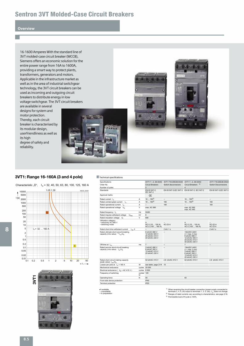
8.5
Overview
Sentron 3VT Molded-Case Circuit Breakers
16-1600 Amperes With the standard line of3VT molded-case circuit breaker (MCCB),Siemens offers an economic solution for the entire power range from 16A to 1600A,providing a smart way to protect plants,transformers, generators and motors.Applicable in the infrastructure market as well as in the area of industrial switchgeartechnology, the 3VT circuit breakers can beused as incoming and outgoing circuitbreakers to distribute energy in low voltage switchgear. The 3VT circuit breakersare available in severaldesigns for system andmotor protection.Thereby, each circuitbreaker is characterised byits modular design,userfriendliness as well asits high degree of safety andreliability.
3VT1: Range 16-160A (3 and 4 pole)
3VT1
8
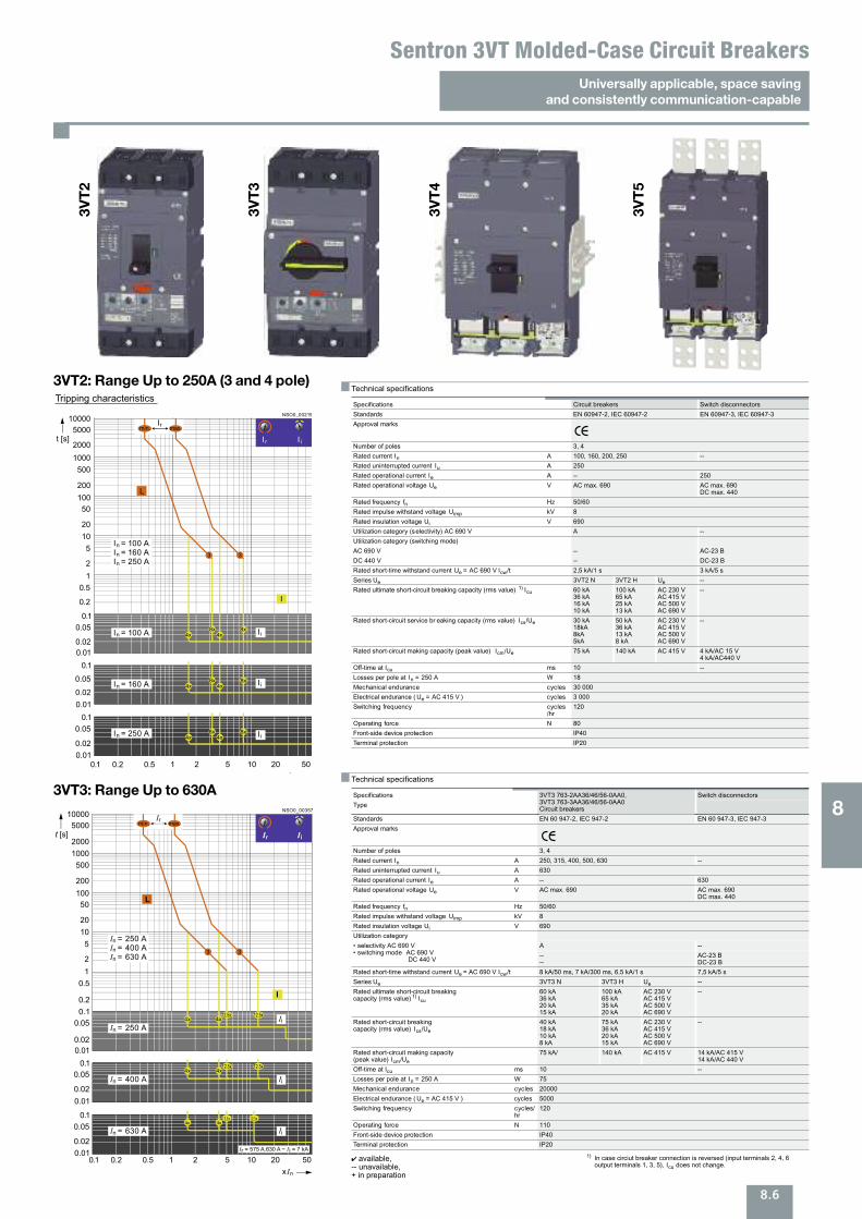
8.6
Universally applicable, space saving and consistently communication-capable
Sentron 3VT Molded-Case Circuit Breakers3VT2
3VT3
NSO0_00357
xIn1 2 5 20 50100.1 0.2 0.5
Ir = 575 A.630 A ~ I i = 7 kA
4x12.5x
4x12.5x
4x12.5x
4x12.5x
4x12.5x
4x12.5x
I
In = 250 A
In = 400 A
In = 630 A Ii
Ii
Ii
In = 250 AIn = 400 AIn = 630 A
L
Ir Ii
0.02
0.02
0.05
0.05
0.01
0.01
20
200
2000
50
500
5000
10
100
1000
10000
t [s]
0.010.02
0.050.1
0.1
0.1
0.2
0.512
5
Irmin. max.
33
3VT3: Range Up to 630A
3VT2: Range Up to 250A (3 and 4 pole)
3VT4
3VT5
8
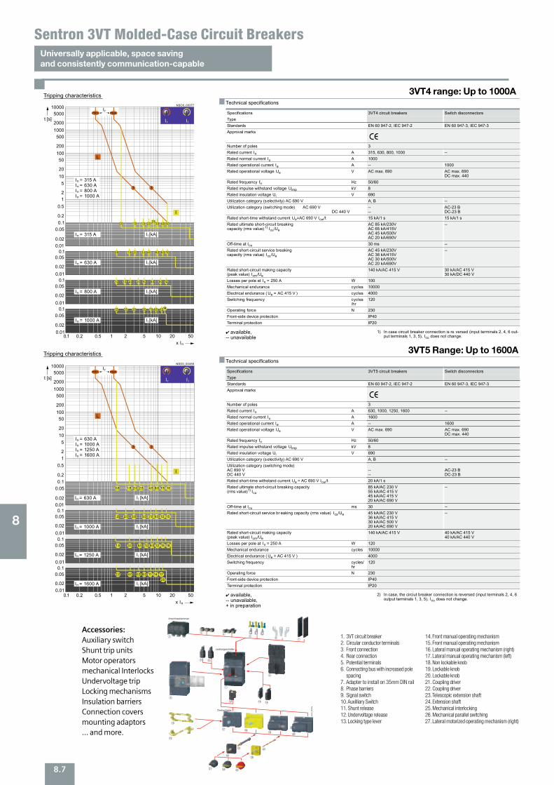
8.7
Universally applicable, space saving and consistently communication-capable
Sentron 3VT Molded-Case Circuit Breakers
3VT4 range: Up to 1000A
Accessories:Auxiliary switchShunt trip unitsMotor operatorsmechanical InterlocksUndervoltage tripLocking mechanismsInsulation barriersConnection coversmounting adaptors ... and more.
3VT5 Range: Up to 1600A
1. 3VT circuit breaker2. Circular conductor terminals3. Front connection4. Rear connection5. Potential terminals6. Connecting bus with increased pole
spacing7. Adapter to install on 35mm DIN rail8. Phase barriers9. Signal switch10. Auxilliary Switch11. Shunt release12. Undervoltage release13. Locking type lever
14. Front manual operating mechanism15. Front manual operating mechanism16. Lateral manual operating mechanism (right) 17. Lateral manual operating mechanism (left)18. Non lockable knob19. Lockable knob20. Lockable knob21. Coupling driver22. Coupling driver23. Telescopic extension shaft24. Extension shaft25. Mechanical interlocking26. Mechanical parallel switching 27. Lateral motorized operating mechanism (right)
8
NS
O0_
0025
8a
2
34
56
8
11
12
1
7
13
9 10
26
27
25
14
15
16
17
21
22
1819
20
23
24
123456
789
101112131415161718
192021222324252627
Leistungsschalter 3VTRundleiteranschlussklemmeFrontseitiger AnschlussRückseitiger AnschlussHilfsleiteranschlussklemmeFrontseitige Anschlussschienen mit vergrößertem PolabstandPhasentrennwändeSeitlicher MotorantriebSpannungsauslöser
UnterspannungsauslöserAdapter für 35 mm DIN SchieneVerriegelung KipphebelAlarmschalterHilfsschalterMechanische ParallelschaltungMechanische VerriegelungFrontseitiger HandantriebFrontseitiger Handantrieb
Seitlicher Handantrieb (rechts)Seitlicher Handantrieb (links)Nicht abschließbare HandhabeSichtblendeAusziehbare VerlängerungswelleAbschließbare HandhabeAbschließbare HandhabeSichtblendeVerlängerungswelle
Drehantriebe
Anschlussklemmen
Leistungsschalter
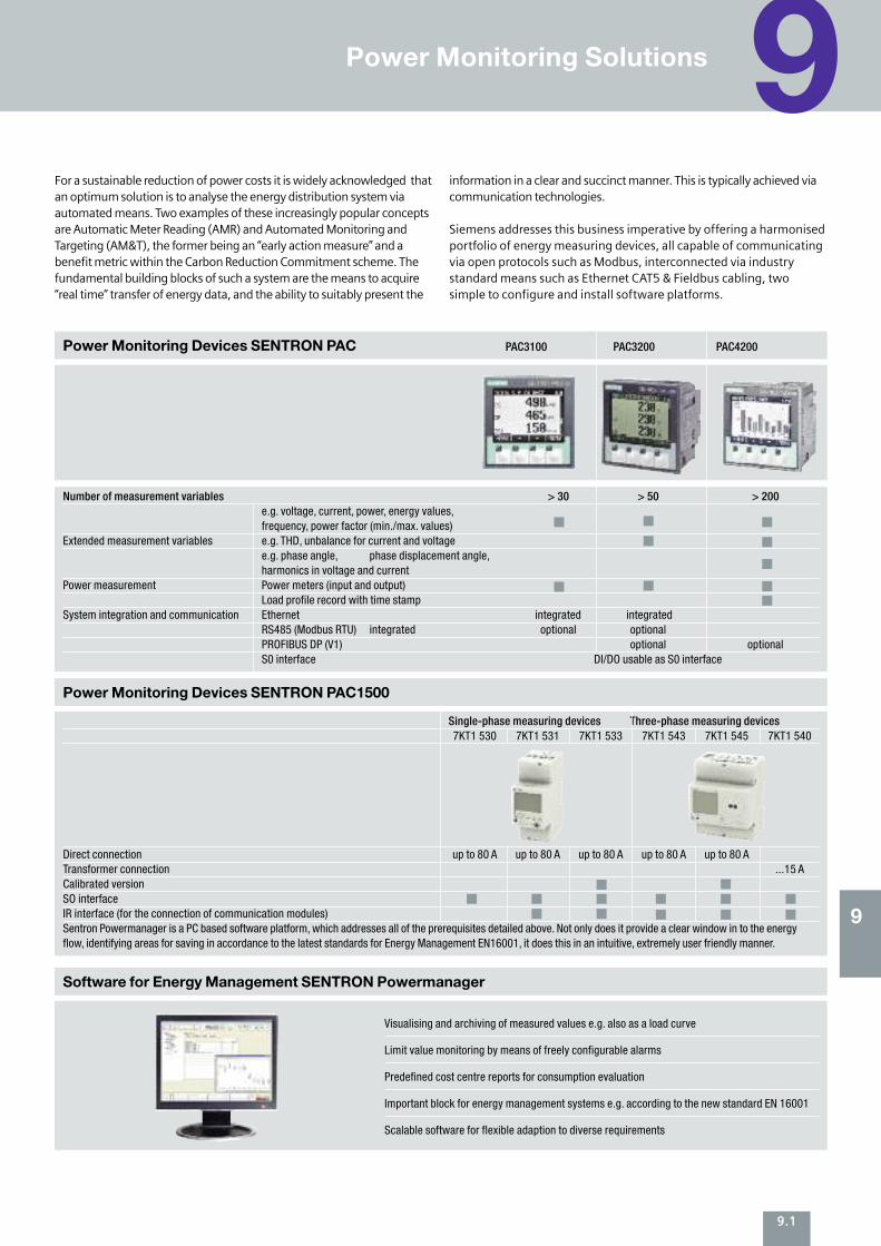
Power Monitoring Solutions 9
9.1
9
For a sustainable reduction of power costs it is widely acknowledged thatan optimum solution is to analyse the energy distribution system viaautomated means. Two examples of these increasingly popular conceptsare Automatic Meter Reading (AMR) and Automated Monitoring andTargeting (AM&T), the former being an “early action measure” and abenefit metric within the Carbon Reduction Commitment scheme. Thefundamental building blocks of such a system are the means to acquire“real time” transfer of energy data, and the ability to suitably present the
information in a clear and succinct manner. This is typically achieved viacommunication technologies.
Siemens addresses this business imperative by offering a harmonisedportfolio of energy measuring devices, all capable of communicatingvia open protocols such as Modbus, interconnected via industrystandard means such as Ethernet CAT5 & Fieldbus cabling, twosimple to configure and install software platforms.
Number of measurement variables > 30 > 50 > 200 e.g. voltage, current, power, energy values,frequency, power factor (min./max. values)
Extended measurement variables e.g. THD, unbalance for current and voltage e.g. phase angle, phase displacement angle, harmonics in voltage and current
Power measurement Power meters (input and output)Load profile record with time stamp
System integration and communication Ethernet integrated integrated RS485 (Modbus RTU) integrated optional optional PROFIBUS DP (V1) optional optional S0 interface DI/DO usable as S0 interface
Power Monitoring Devices SENTRON PAC
Single-phase measuring devices Three-phase measuring devices 7KT1 530 7KT1 531 7KT1 533 7KT1 543 7KT1 545 7KT1 540
Direct connection up to 80 A up to 80 A up to 80 A up to 80 A up to 80 A Transformer connection ...15 A Calibrated version SO interface IR interface (for the connection of communication modules) Sentron Powermanager is a PC based software platform, which addresses all of the prerequisites detailed above. Not only does it provide a clear window in to the energyflow, identifying areas for saving in accordance to the latest standards for Energy Management EN16001, it does this in an intuitive, extremely user friendly manner.
Power Monitoring Devices SENTRON PAC1500
Visualising and archiving of measured values e.g. also as a load curve
Limit value monitoring by means of freely configurable alarms
Predefined cost centre reports for consumption evaluation
Important block for energy management systems e.g. according to the new standard EN 16001
Scalable software for flexible adaption to diverse requirements
Software for Energy Management SENTRON Powermanager
PAC3100 PAC3200 PAC4200
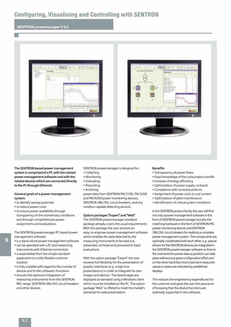
9.2
SENTRON powermanager V 2.0
Configuring, Visualising and Controlling with SENTRON
9
The SENTRON-based power managementsystem is comprised of a PC with the relatedpower management software and with therelated devices which are connected directlyto the PC through Ethernet.
General goals of a power managementsystem:• to identify savings potential • to reduce power costs• to ensure power availability throughtransparency of the momentary conditionsand through comprehensive powerassignments and evaluations.
The SENTRON powermanager PC-based powermanagement software• is a stand-alone power management software• can be operated with a PC and measuringinstruments with Ethernet connection
• is expandable from the simple standardapplication to a fully flexible customersolution
• is fully scalable with regard to the number ofdevices and to the software's functions
• ensures the optimum integration ofmeasuring instruments from the SENTRONPAC range, SENTRON 3WL/3VL circuit breakersand other devices
SENTRON powermanager is designed for:• Collecting• Monitoring• Evaluating• Presenting• Archiving power data from SENTRON PAC3100, PAC3200and PAC4200 power monitoring devices,SENTRON 3WL/3VL circuit breakers, and anymodbus-capable detecting devices.
Option packages "Expert" and "Web"The SENTRON powermanager standardpackage already covers the usual requirements.With this package the user receives aneasy-to-engineer power management softwarewhich enables the data detected by themeasuring instruments to be read out,presented, archived and processed in basicevaluations.
With the option package "Expert" the userreceives full flexibility for the presentation ofgraphic interfaces (e.g. single-linepresentations) in order to integrate his ownimages and devices. The data/images aredisplayed as standard using a Windows clientwhich must be installed on the PC. The optionpackage "Web" is offered to meet the market'sdemands for web presentation.
Benefits• Transparency of power flows• Exact knowledge of the consumption profile• Increase of energy efficiency• Optimization of power supply contracts• Compliance with contractual terms• Assignment of power costs to cost centers• Optimization of plant maintenance• Identification of critical system conditions
In the SENTRON product family the user will findnot only a power management software in theform of SENTRON powermanager but also thematching hardware in the form of SENTRON PACpower monitoring devices and SENTRON3WL/3VL circuit breakers for realizing a completepower management system. The components areoptimally coordinated with each other, e.g. specialdrivers for the SENTRON devices are integrated inthe SENTRON powermanager software so that onthe one hand the power data acquisition can takeplace without any great configuration effort andon the other hand the most important measuredvalues or states are indicated by predefineddisplays.
This reduces the engineering expenditures forthe customer and gives the user the assuranceof knowing that the device functions areoptimally supported in the software.
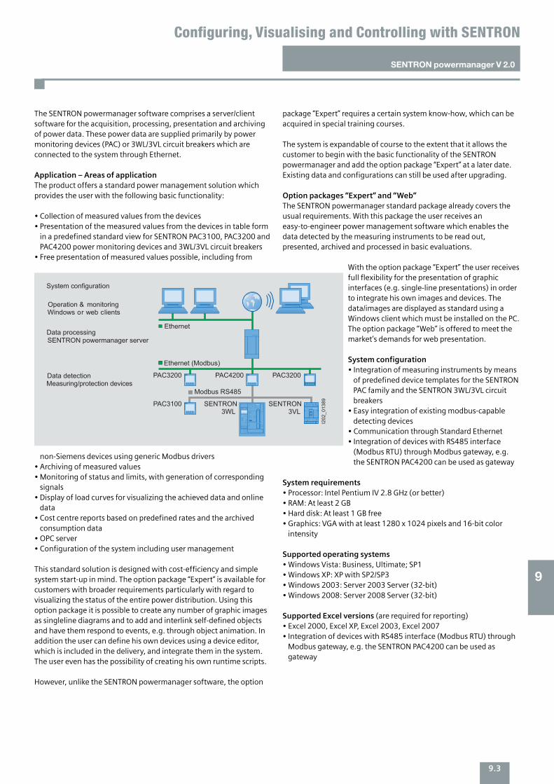
9.3
The SENTRON powermanager software comprises a server/clientsoftware for the acquisition, processing, presentation and archivingof power data. These power data are supplied primarily by powermonitoring devices (PAC) or 3WL/3VL circuit breakers which areconnected to the system through Ethernet.
Application – Areas of application The product offers a standard power management solution whichprovides the user with the following basic functionality:
• Collection of measured values from the devices • Presentation of the measured values from the devices in table formin a predefined standard view for SENTRON PAC3100, PAC3200 andPAC4200 power monitoring devices and 3WL/3VL circuit breakers
• Free presentation of measured values possible, including from
non-Siemens devices using generic Modbus drivers • Archiving of measured values • Monitoring of status and limits, with generation of correspondingsignals
• Display of load curves for visualizing the achieved data and onlinedata
• Cost centre reports based on predefined rates and the archivedconsumption data
• OPC server • Configuration of the system including user management
This standard solution is designed with cost-efficiency and simplesystem start-up in mind. The option package “Expert” is available forcustomers with broader requirements particularly with regard tovisualizing the status of the entire power distribution. Using thisoption package it is possible to create any number of graphic imagesas singleline diagrams and to add and interlink self-defined objectsand have them respond to events, e.g. through object animation. Inaddition the user can define his own devices using a device editor,which is included in the delivery, and integrate them in the system.The user even has the possibility of creating his own runtime scripts.
However, unlike the SENTRON powermanager software, the option
package “Expert” requires a certain system know-how, which can beacquired in special training courses.
The system is expandable of course to the extent that it allows thecustomer to begin with the basic functionality of the SENTRONpowermanager and add the option package “Expert” at a later date.Existing data and configurations can still be used after upgrading.
Option packages “Expert” and “Web” The SENTRON powermanager standard package already covers theusual requirements. With this package the user receives aneasy-to-engineer power management software which enables thedata detected by the measuring instruments to be read out,presented, archived and processed in basic evaluations.
With the option package “Expert” the user receivesfull flexibility for the presentation of graphicinterfaces (e.g. single-line presentations) in orderto integrate his own images and devices. Thedata/images are displayed as standard using aWindows client which must be installed on the PC.The option package “Web” is offered to meet themarket’s demands for web presentation.
System configuration • Integration of measuring instruments by meansof predefined device templates for the SENTRONPAC family and the SENTRON 3WL/3VL circuitbreakers
• Easy integration of existing modbus-capabledetecting devices
• Communication through Standard Ethernet • Integration of devices with RS485 interface(Modbus RTU) through Modbus gateway, e.g.the SENTRON PAC4200 can be used as gateway
System requirements • Processor: Intel Pentium IV 2.8 GHz (or better) • RAM: At least 2 GB • Hard disk: At least 1 GB free • Graphics: VGA with at least 1280 x 1024 pixels and 16-bit colorintensity
Supported operating systems • Windows Vista: Business, Ultimate; SP1 • Windows XP: XP with SP2/SP3 • Windows 2003: Server 2003 Server (32-bit) • Windows 2008: Server 2008 Server (32-bit)
Supported Excel versions (are required for reporting) • Excel 2000, Excel XP, Excel 2003, Excel 2007 • Integration of devices with RS485 interface (Modbus RTU) throughModbus gateway, e.g. the SENTRON PAC4200 can be used asgateway
SENTRON powermanager V 2.0
Configuring, Visualising and Controlling with SENTRON
9
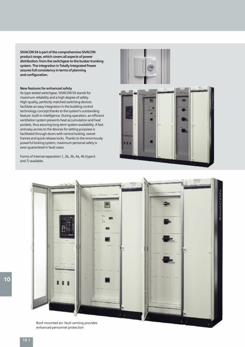
10
10.1
SIVACON S4 is part of the comprehensive SIVACONproduct range, which covers all aspects of powerdistribution: from the switchgear to the busbar trunkingsystem. The integration in Totally Integrated Powerassures full consistency in terms of planning and configuration.
New features for enhanced safetyAs type-tested switchgear, SIVACON S4 stands formaximum reliability and a high degree of safety.High-quality, perfectly matched switching devicesfacilitate an easy integration in the building controltechnology concept thanks to the system’s outstandingfeature: built-in intelligence. During operation, an efficientventilation system prevents heat accumulation and heatpockets, thus assuring long-term system availability. A fastand easy access to the devices for setting purposes isfacilitated through doors with central locking, swivelframes and quick-release locks. Thanks to the enormouslypowerful locking system, maximum personal safety iseven guaranteed in fault cases.
Forms of internal separation 1, 2b, 3b, 4a, 4b (type 6 and 7) available.
Roof mounted arc-fault venting providesenhanced personnel protection
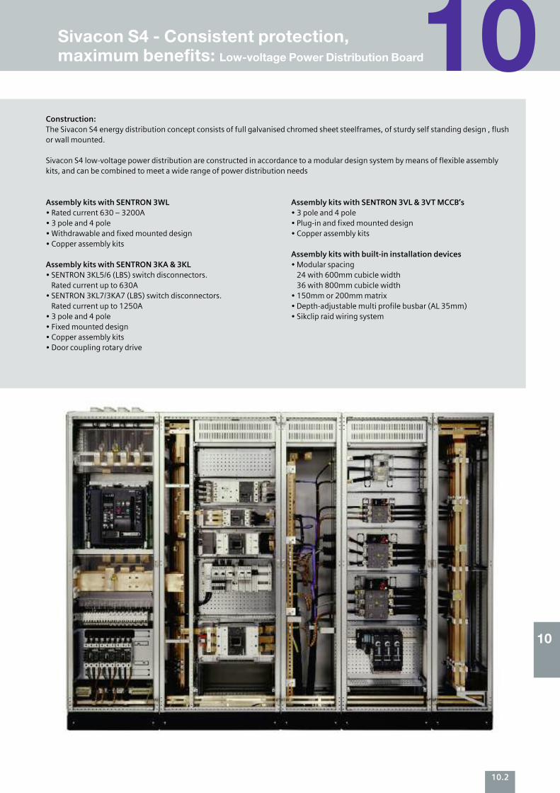
Construction: The Sivacon S4 energy distribution concept consists of full galvanised chromed sheet steelframes, of sturdy self standing design , flushor wall mounted.
Sivacon S4 low-voltage power distribution are constructed in accordance to a modular design system by means of flexible assemblykits, and can be combined to meet a wide range of power distribution needs
Assembly kits with SENTRON 3WL • Rated current 630 – 3200A • 3 pole and 4 pole • Withdrawable and fixed mounted design • Copper assembly kits
Assembly kits with SENTRON 3KA & 3KL • SENTRON 3KL5/6 (LBS) switch disconnectors. Rated current up to 630A
• SENTRON 3KL7/3KA7 (LBS) switch disconnectors. Rated current up to 1250A
• 3 pole and 4 pole • Fixed mounted design • Copper assembly kits • Door coupling rotary drive
Assembly kits with SENTRON 3VL & 3VT MCCB’s• 3 pole and 4 pole • Plug-in and fixed mounted design • Copper assembly kits
Assembly kits with built-in installation devices • Modular spacing 24 with 600mm cubicle width 36 with 800mm cubicle width
• 150mm or 200mm matrix • Depth-adjustable multi profile busbar (AL 35mm) • Sikclip raid wiring system
10.2
10
10Sivacon S4 - Consistent protection, maximum benefits: Low-voltage Power Distribution Board
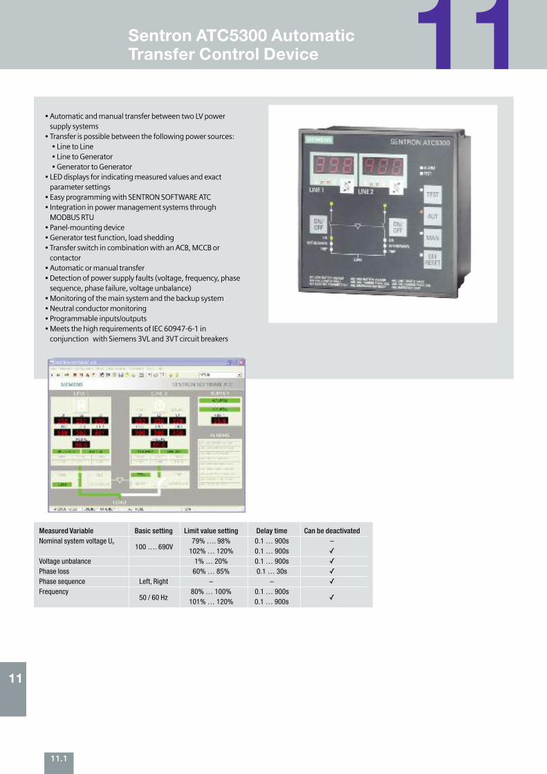
11Sentron ATC5300 Automatic Transfer Control Device
• Automatic and manual transfer between two LV powersupply systems
• Transfer is possible between the following power sources: • Line to Line • Line to Generator • Generator to Generator
• LED displays for indicating measured values and exactparameter settings
• Easy programming with SENTRON SOFTWARE ATC • Integration in power management systems throughMODBUS RTU
• Panel-mounting device • Generator test function, load shedding • Transfer switch in combination with an ACB, MCCB orcontactor
• Automatic or manual transfer • Detection of power supply faults (voltage, frequency, phasesequence, phase failure, voltage unbalance)
• Monitoring of the main system and the backup system • Neutral conductor monitoring • Programmable inputs/outputs • Meets the high requirements of IEC 60947-6-1 inconjunction with Siemens 3VL and 3VT circuit breakers
Measured Variable Basic setting Limit value setting Delay time Can be deactivated Nominal system voltage Un 79% …. 98% 0.1 … 900s –
102% … 120% 0.1 … 900s
Voltage unbalance 1% … 20% 0.1 … 900s
Phase loss 60% … 85% 0.1 … 30s
Phase sequence Left, Right – –
Frequency 80% … 100% 0.1 … 900s 101% … 120% 0.1 … 900s
100 …. 690V
50 / 60 Hz
11
11.1
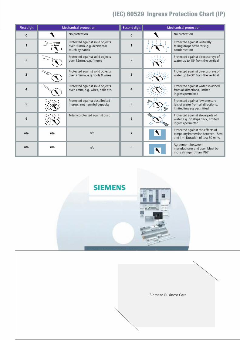
No protection0
Protected against solid objectsover 50mm, e.g. accidentaltouch by hands
1
Protected against solid objectsover 12mm, e.g. fingers2
Protected against solid objectsover 2.5mm, e.g. tools & wires 3
Protected against solid objectsover 1mm, e.g. wires, nails etc. 4
Protected against dust limitedingress, not harmful deposits5
Totally protected against dust6
n/an/a
n/an/a
Mechanical protection
No protection0
Protected against verticallyfalling drops of water e.g.condensation
1
Protected against direct sprays ofwater up to 15o from the vertical2
Protected against direct sprays ofwater up to 60o from the vertical3
Protected against water splashedfrom all directions, limitedingress permitted
4
Protected against low pressurejets of water from all directions,limited ingress permitted
5
Protected against strong jets ofwater e.g. on ships deck, limitedingress permitted
6
Protected against the effects oftemporary immersion between 15cmand 1m. Duration of test 30 mins
7
Agreement betweenmanufacturer and user. Must bemore stringent than IP67
8
Second digit Mechanical protection
n/a
n/a
First digit
(IEC) 60529 Ingress Protection Chart (IP)
Siemens Business Card

44
www.industry.siemens.co.uk/buildingtechnologies/uk
Contact Information
SiemensI BT LV Sharston Road Wythenshawe Manchester M22 4RA
Tel: +44 (0) 161 998 5454 Fax: +44 (0) 8456 053114
For further information contact us by telephone or by email to [email protected]
Please read and recycle
The information provided in this brochurecontains merely general descriptions orcharacteristics of performance which in case ofactual use do not always apply as described orwhich may change as a result of furtherdevelopment of the products. An obligation to provide the respective characteristics shall onlyexist if expressly agreed in the terms of contract. All product designations may be trademarks orproduct names of Siemens AG or suppliercompanies whose use by third parties for theirown purposes could violate the rights of theowners.
Subject to change without prior notice
Printed in the United Kingdom © Siemens AG 2011
Rd&M 201791 – 07.11