information must be transformed into signals before it can be transformed across the communication...
TRANSCRIPT
Information must be transformed into signals before it can be transformed across the communication media
How this information is transformed depends upon its original format and on the format of the communication hardware
Introduction
If you want to send a letter by a smoke signal, you need to know which smoke patterns make which words in your message before building the fire
Words are the Information and the puffs of smoke are representation of that information
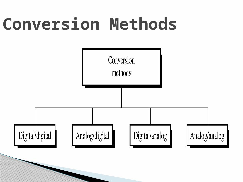
Conversion Methods
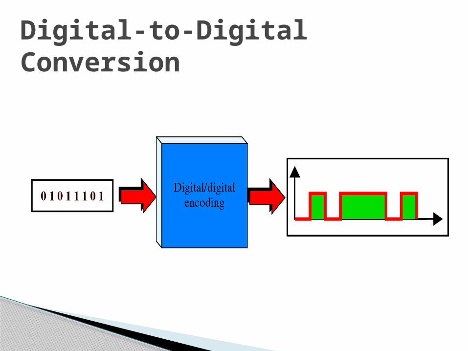
Digital-to-Digital conversion/encoding is the representation of digital information by digital signal
For Example:◦When you transmit data from Computer to the Printer, both original and transmitted data have to be digital
Digital-to-Digital Conversion
Digital-to-Digital Conversion
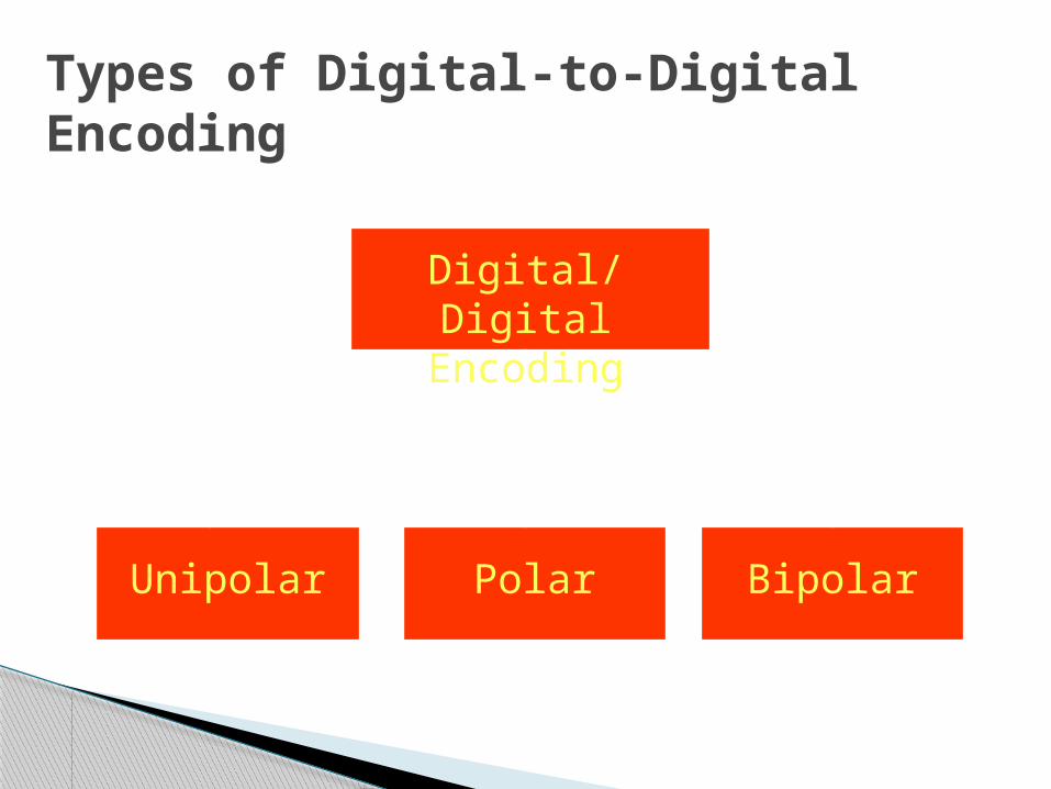
Types of Digital-to-Digital Encoding
Digital/Digital Encoding
Unipolar Polar Bipolar
Simple and Primitive
Almost Obsolete Today
Study provides introduction to concepts and problems involved with more complex encoding systems
Unipolar Encoding
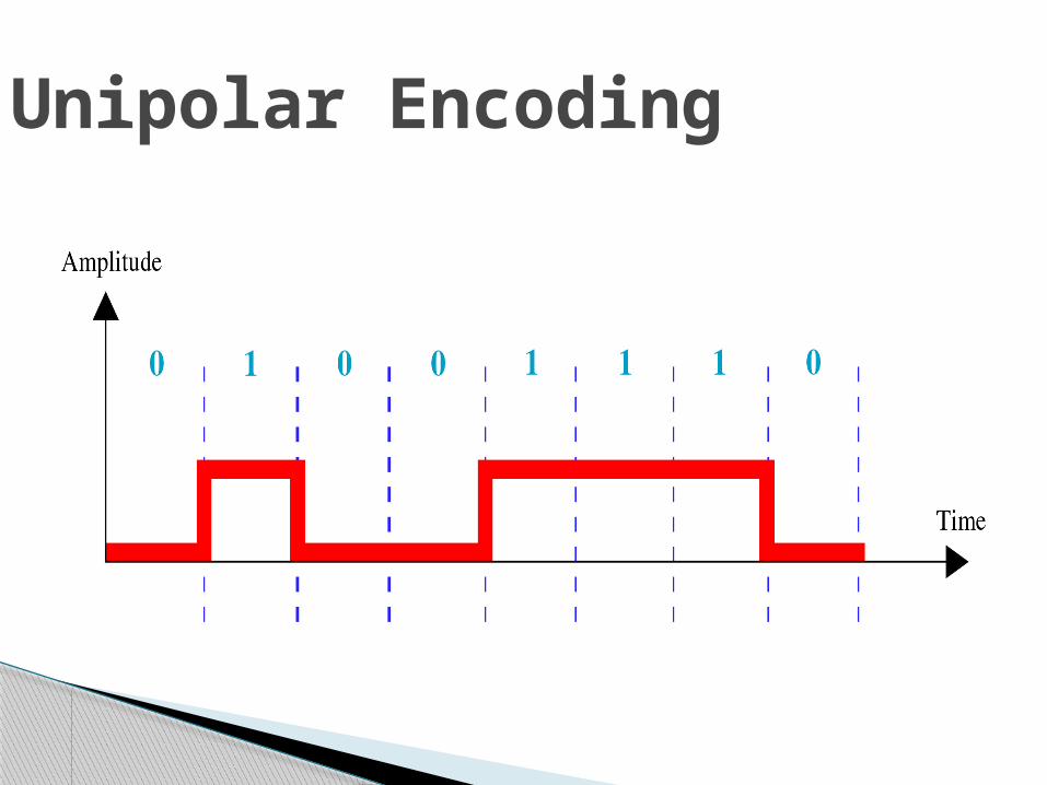
Unipolar Encoding
PROS◦Straight Forward and Simple◦Inexpensive to Implement
CONS◦DC Component ◦Synchronization
Pros and Cons of Unipolar Encoding
DC Component Average Amplitude of a unipolar encoded signal
is non-zero This is called DC Component I.e. a component
with zero frequency When a signal contains a DC Component, it
cannot travel through a Tx. Medium that cannot handle DC components
Synchronization◦ When the signal is unvarying, Rx. Cannot
determine the beginning and ending of each bit◦ Synchronization Problem can occur when data
consists of long streams of 1’s or 0’s ◦ Therefore, Rx has to rely on a TIMER
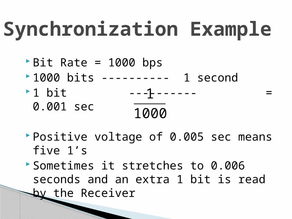
Bit Rate = 1000 bps 1000 bits ---------- 1 second 1 bit ---------- = 0.001 sec
Positive voltage of 0.005 sec means five 1’s
Sometimes it stretches to 0.006 seconds and an extra 1 bit is read by the Receiver
Synchronization Example
1000
1
Polar encoding uses two voltage levels◦One positive and one negative
Average voltage level on the line is reduced
DC Component problem of Unipolar encoding is alleviated
Polar Encoding
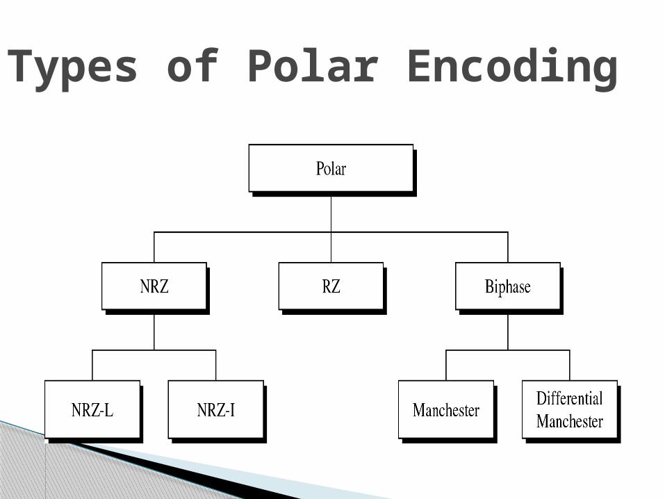
Types of Polar Encoding
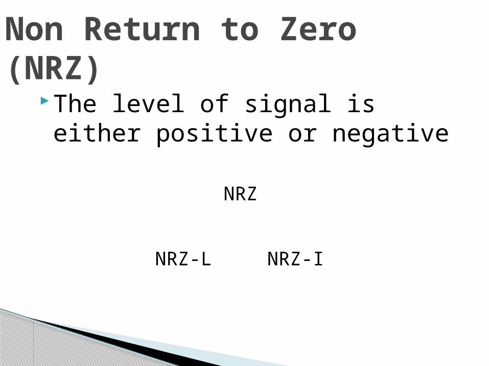
The level of signal is either positive or negative
Non Return to Zero (NRZ)
NRZ
NRZ-L NRZ-I
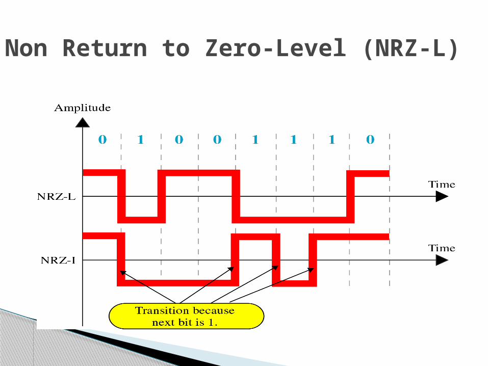
Non Return to Zero-Level (NRZ-L)
The inversion of the level represents a 1 bit
A bit 0 is represented by no change NRZ-I is superior to NRZ-L due to synchronization provided by signal change each time a 1 bit is encountered
The string of 0’s can still cause problem but since 0’s are not as likely, they are less of a problem
NRZ-I
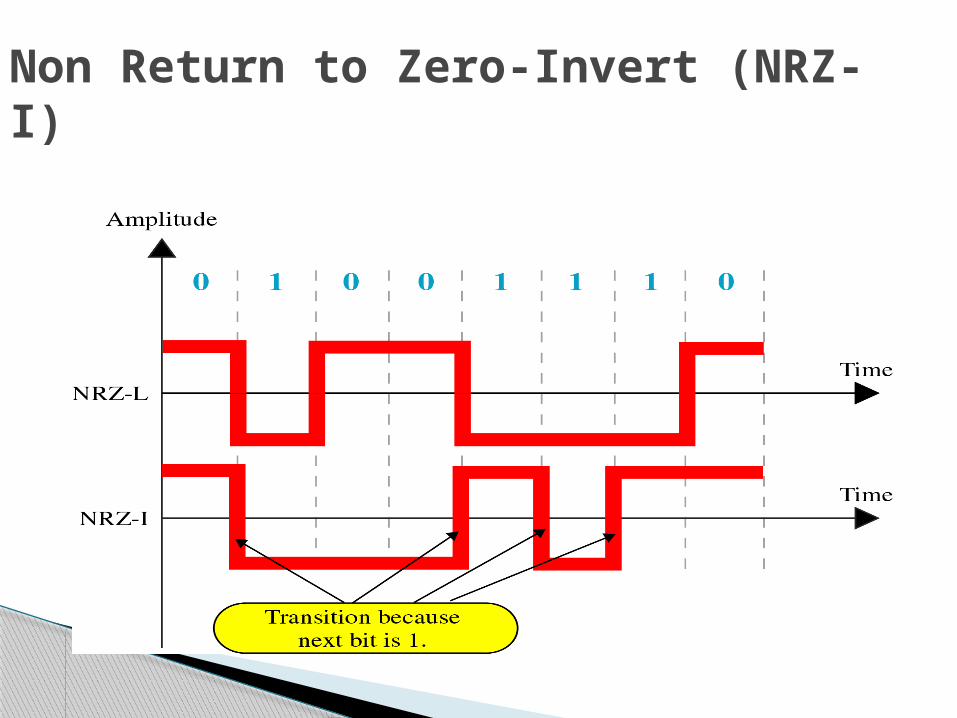
Non Return to Zero-Invert (NRZ-I)

Types of Polar Encoding
◦ Any time, data contains long strings of 1’s or 0’s, Rx can loose its timing
◦ In unipolar, we have seen a good solution is to send a separate timing signal but this solution is both expensive and full of error
◦ A better solution is to somehow include synch in encoded signal somewhat similar to what we did in NRZ-I but it should work for both strings of 0 & 1
◦ One solution is RZ encoding which uses 3 values : Positive, Negative and Zero
Return to Zero (RZ)
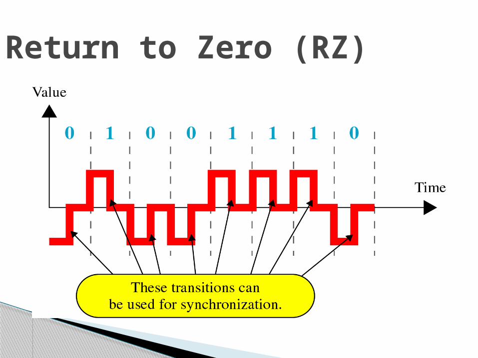
◦ Signal changes not b/w bits but during each bit◦ Like NRZ-L , +ve voltage means 1 and a –ve
voltage means 0, but unlike NRZ- L, half way through each bit interval, the signal returns to zero
◦ A 1 bit is represented by positive to zero and a 0 is represented by negative to zero transition
◦ The only problem with RZ encoding is that it requires two signal changes to encode one bit and therefore occupies more BANDWIDTH
◦ But of the 3 alternatives we have discussed, it is most effective
RZ
Return to Zero (RZ)
Biphase Encoding
Best existing solution to the problem of Synchronization
Signal changes at the middle of bit interval but does not stop at zero
Biphase Encoding
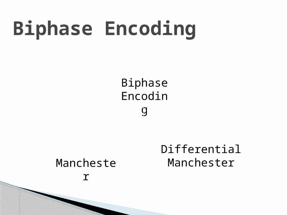
Biphase Encoding
Differential Manchester Manchester

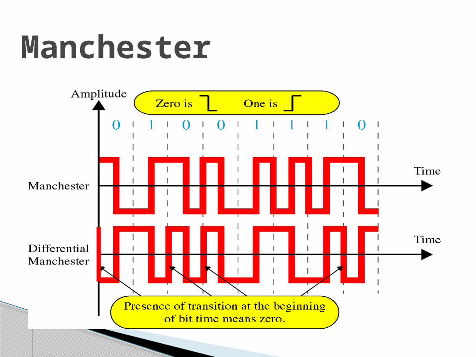
Uses inversion at the middle of each bit interval for both synchronization and bit representation
Negative-to-Positive Transition= 1 Positive-to-Negative Transition = 0 By using a single transition for a dual
purpose, Manchester achieves the same level of synchronization as RZ but with only two levels of amplitude
Manchester
Manchester
Inversion at the middle of the bit interval is
used for Synchronization but presence or absence of an additional transition at the beginning of bit interval is used to identify a bit
A transition means binary 0 & no transition means binary 1
Requires 2 signal changes to represent binary 0 but only one to represent binary 1
Differential Manchester
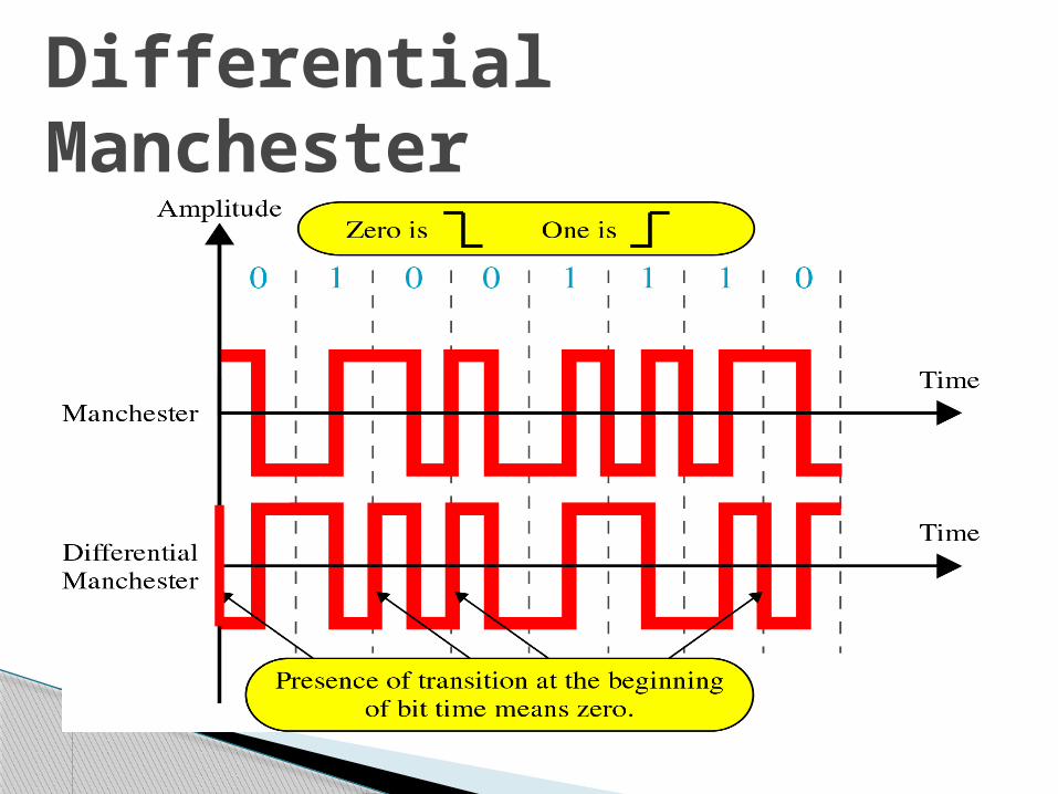
Differential Manchester
Bipolar Encoding
Like RZ, it uses three voltage levels:
Unlike RZ, zero level is used to represent binary 0
Binary 1’s are represented by alternate positive and negative voltages
Bipolar Encoding
Alternate Mark Inversion (AMI)
Simplest type of Bipolar Encoding
Mark Comes from Telegraphy (1)
Alternate Mark Inversion means Alternate ‘1’ Inversion
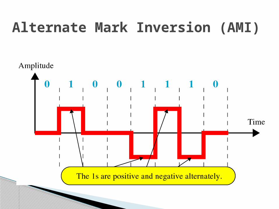
Alternate Mark Inversion (AMI)
By inverting on each occurrence of 1, AMI accomplishes 2 things:
The DC component is zero Long sequence of 1’s stay synchronized No mechanism of ensuring synch is there
for long stream of 0’s
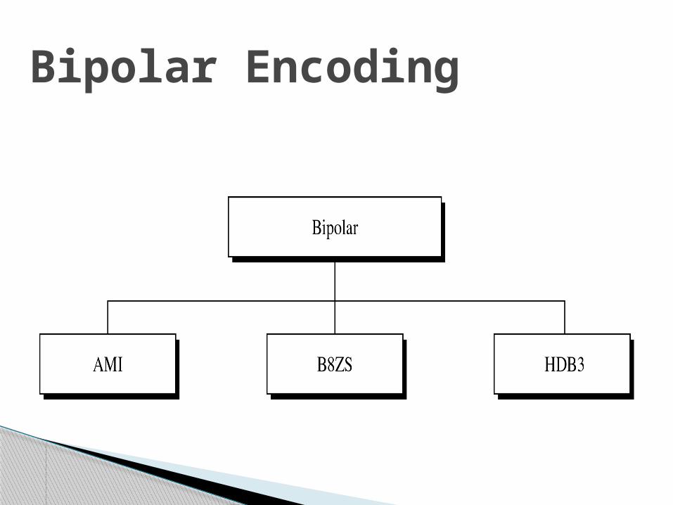
Two variations are developed to solve the problem of synchronization of sequential 0’s
B8ZS used in North America HDB3 used in Europe & Japan
AMI
Convention adopted in North America to provide synch for long string of zeros
Difference b/w AMI and B8ZS occurs only when 8 or more consecutive zeros are encountered
Forces artificial signal changes called VIOLATIONS
Each time eight 0’s occur , B8ZS introduces changes in pattern based on polarity of previous 1 (the ‘1’ occurring just before zeros)
B8ZS
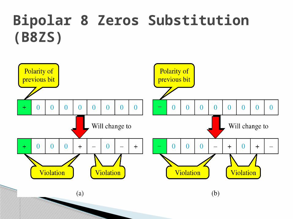
Bipolar 8 Zeros Substitution (B8ZS)
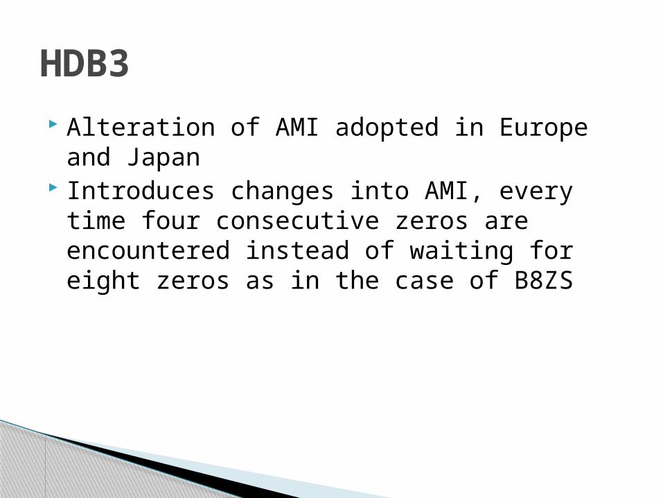
Alteration of AMI adopted in Europe and Japan
Introduces changes into AMI, every time four consecutive zeros are encountered instead of waiting for eight zeros as in the case of B8ZS
HDB3
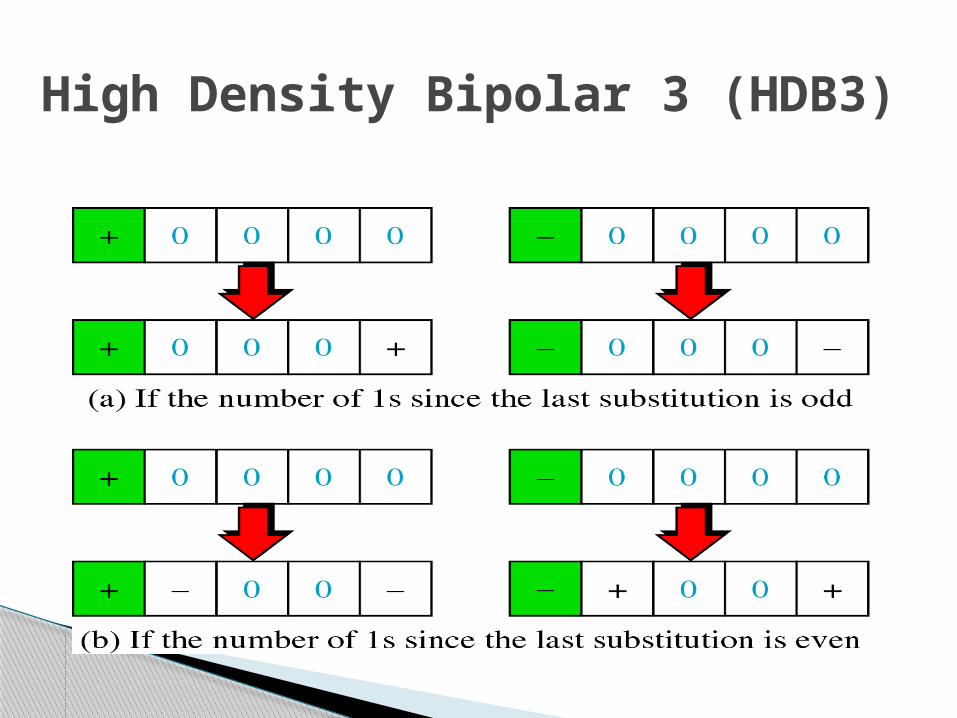
High Density Bipolar 3 (HDB3)