zn-7100-de500-g umd284f45nftegze.cloudfront.net/zcomax/zdc_zn-7100-de500-g...party responsible for...
TRANSCRIPT
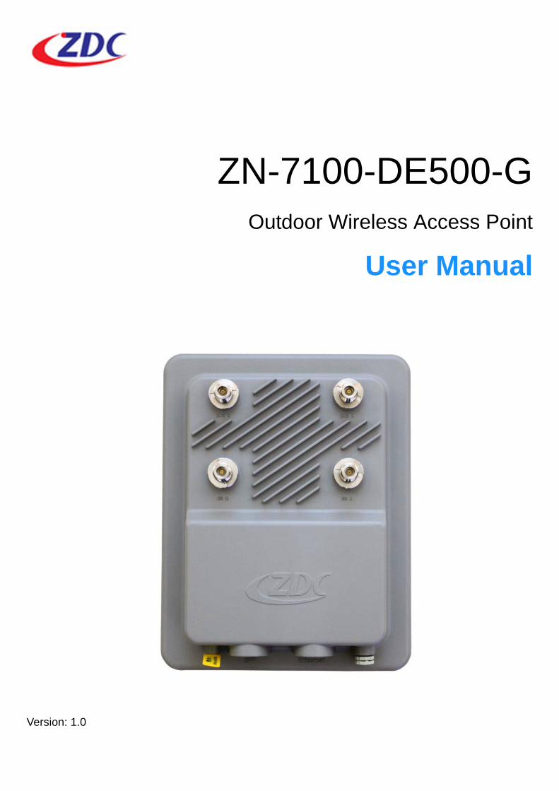
ZN-7100-DE500-GOutdoor Wireless Access Point
User Manual
Version: 1.0

Table of Contents
Table of Contents
Chapter 1Product Overview. . . . . . . . . . . . . . . . . . . . . . . . . . . . . . . . . . . . . . . . . . . . . . . . . . . .1
Introduction.................................................................................................................... 1
Key Features ................................................................................................................. 1
Package Contents ......................................................................................................... 2
Product Views................................................................................................................ 3
Top View ............................................................................................................. 3
Bottom View ........................................................................................................ 3
LED Definitions.............................................................................................................. 4
Chapter 2Safety Information . . . . . . . . . . . . . . . . . . . . . . . . . . . . . . . . . . . . . . . . . . . . . . . . . . .5
Safety Requirements ..................................................................................................... 5
Electrostatic Discharge Requirements ................................................................ 5
Temperature/Humidity Requirements ................................................................. 5
Anti-Interference Requirements .......................................................................... 5
Grounding Requirements .................................................................................... 6
Installation Precautions ................................................................................................. 6
Management Precaution ............................................................................................... 6
Chapter 3Installing the Wireless AP . . . . . . . . . . . . . . . . . . . . . . . . . . . . . . . . . . . . . . . . . . . . .7
Before Installation.......................................................................................................... 7
Choosing the Location......................................................................................... 7
Surveying the Installation Site ............................................................................. 7
Determining the Optimal Mounting Location and Orientation.............................. 8
Waterproofing the Outdoor LAN Cable.......................................................................... 9
Hardware Installation................................................................................................... 10
Mounting on a Pole ........................................................................................... 10
Installing Antennas ............................................................................................ 11
Connecting to a Power Source.................................................................................... 11
First-Time Connection and Configuration.................................................................... 13
Connecting to a PC ........................................................................................... 13
Connecting the Wireless AP to Your Network................................................... 14
Changing the Default Password........................................................................ 16
Chapter 4Accessing the Wireless AP . . . . . . . . . . . . . . . . . . . . . . . . . . . . . . . . . . . . . . . . . . .17
Setting Up the Access Portal ....................................................................................... 17
Navigating the Access Portal....................................................................................... 18
Factory Default Settings .............................................................................................. 22
i

Table of Contents
Chapter 5Configuring the Wireless Access Point . . . . . . . . . . . . . . . . . . . . . . . . . . . . . . . . .28
General Menu.............................................................................................................. 28
Current IP Settings ............................................................................................ 29
Configuring Wireless Switch Settings................................................................ 29
Advanced Setting .............................................................................................. 30
Viewing the System Log.................................................................................... 32
Basic Setup Menu ....................................................................................................... 33
Configuring the AP as a Bridge ......................................................................... 34
RF Configure Menu ..................................................................................................... 35
Configuring Wireless Settings ........................................................................... 36
Configuring Security Profile (Virtual AP) Settings ............................................. 38
Network Authentication ..................................................................................... 41
Data Encryption................................................................................................. 42
Configuring the WDS Settings (Bridge Mode)................................................... 42
Configuring RADIUS Settings ........................................................................... 43
Configuring the WAPI Settings.......................................................................... 46
Configuring Access Control............................................................................... 47
Advanced Setup .......................................................................................................... 49
Management Settings.................................................................................................. 51
Configuring Management Control ..................................................................... 51
Configuring Remote Settings ............................................................................ 53
Changing the Password .................................................................................... 57
Restoring the Default Password ....................................................................... 57
Upgrading Firmware.......................................................................................... 57
Configuring Backup/Restore Settings .............................................................. 58
Restoring Factory Default Settings ................................................................... 60
Using the Ping Function .................................................................................... 60
Rebooting the Wireless AP ............................................................................... 61
Configuring QoS Mapping ................................................................................. 61
Information Menu......................................................................................................... 62
Checking System Logs...................................................................................... 64
Checking the Station List................................................................................... 65
Checking the Statistics ...................................................................................... 65
Scanning Adjacent APs/STAs ........................................................................... 66
ii

iii
Federal Communication Commission Interference Statement
This equipment has been tested and found to comply with the limits for a Class B digital device, pursuant to Part 15 of the FCC Rules. These limits are designed to provide reasonable protection against harmful interference in a commercial environment. This equipment generates, uses, and can radiate radio frequency energy and, if not installed and used in accordance with the instructions, may cause harmful interference to radio communications. How-ever, there is no guarantee that interference will not occur in a particular installation. Operation of this equipment in a residential area is likely to cause harmful interference in which case user will be required to correct the interfer-ence at their own expense. Try to correct the interference by one or more of the following measures:
Verify that the ambient temperature remains between 32 to 104° F (0 to 40° C), taking into account the elevated temperatures when installed in a rack or enclosed space.
Verify the integrity of the electrical ground before installing the device.
FCC Caution: Any changes or modifications not expressly approved by the party responsible for compliance could void the user's authority to operate this equipment.
Warranty
Hardware warranty is for one (1) year from date of shipment. Distributor war-rants that hardware will conform to the current relevant published specifica-tions and will be free from material defects in material and workmanship under normal use and service.
IN NO EVENT SHALL DISTRIBUTOR BE LIABLE TO YOU OR ANY OTHER PARTY FOR ANY DIRECT, INDIRECT, GENERAL, SPECIAL, INCIDENTAL, CONSEQUENTIAL, EXEMPLARY OR OTHER DAMAGE RISING OUT OF THE USE OR INABILITY TO USE THE PRODUCT (INCLUDING, WITHOUT LIMITATION, DAMAGES FOR LOSS OF BUSINESS PROFITS, BUSINESS INTERRUPTION, LOSS OF BUSINESS INFORMATION OR ANY OTHER PECUNIARY LOSS, OR FROM ANY BREACH OF WARRANTY, EVEN IF DISTRIBUTOR HAS BEEN ADVISED OF THE POSSIBILITY OF SUCH DAMAGES. LIABILITY IN NO CASE SHALL EXCEED THE AMOUNT YOU PAID FOR THE PRODUCT.

iv
Conventions
This manual uses typographic conventions to draw your attention to useful information or cautions to prevent personal injury or damage to the device.
Caution - Alerts you that improper operation may cause physical harm or damage to the device.
Note: Provides additional explanation or information.
Copyright
Copyright © 2013 Z-Com Inc. All rights reserved. No part of this publication may be reproduced, adapted, stored in a retrieval system, translated into any language, or transmitted in any form or by any means without the written per-mission of the manufacturer.
About This Manual
This user manual is intended to guide professional installers in installing and configuring the ZN-7100-DE500-G wireless access point, and in building the infrastructure centered on it. It includes procedures to assist you in avoiding unforeseen problems.

Introduction
Chapter 1
Product Overview
IntroductionZN-7100-DE500-G wireless access point extends outdoor wireless coverage by operating at both 2.4GHz and 5GHz frequencies using multiple-input multi-ple-output wireless technology in combination with orthogonal frequency divi-sion multiplexing (MIMO-OFDM) modulation techniques. Supporting a maximum data rate of 300Mbps per single band and equipped with optical interfaces, the ZN-7100-DE500-G is capable of high transfer rates, receiver sensitivity and long transmission distance, making it an ideal solution for broadband Last Mile services and hotspot backhauling.
Key Features Simultaneous operation at both 2.4GHz and 5GHz frequencies
2 x 2 MIMO support
Optical interface supporting SFP modules
Integrated with both Fat AP and Fit AP modes
Supports wireless multimedia extensions (WMM)
Link integrity
Automatic power control
Automatic frequency control
Load balancing
1Product Overview

Package Contents
Package Contents
ZN-7100-DE500-G Wireless Access Point Pole Mount Clip and Bracket
Pole Mount Securing Rings Locking Nut and Sealing Cap
Screw Kit 48VDC Power Adapter + Power cord
PoE Injector Kit Warranty Card
PoE
POWERNETWORK
Warranty Card
2Product Overview

Product Views
Product Views
Top View
Figure 1-1. ZN-7100-DE500-G Top View
Bottom View
Figure 1-2. ZN-7100-DE500-G Bottom View
Table 1-1. ZN-7100-DE500-G Top View
No. Item
1 2.4GHz RF Antenna Connector
2 2.4GHz RF Antenna Connector
3 5GHz RF Antenna Connector
4 5GHz RF Antenna Connector
1 2
3 4
1 2 3 4 5
3Product Overview

LED Definitions
LED Definitions
Figure 1-3. LED Indicators on the PoE Injector
Table 1-2. ZN-7100-DE500-G Bottom View
No. Item
1 GND
2 SFP
3 Ethernet
4 Reset Button
5 Ventilation Hole
Table 1-3. LED Definitions
No. Name State Description
1. PWR On (green)Power is supplied to the device through the Ethernet port.
1
4Product Overview

Safety Requirements
Chapter 2
Safety Information
Safety RequirementsBefore you begin installing the device, read through the following safety guidelines to prevent personal injury or property damage.
Seek assistance from a trained professional installer, especially if it is your first time to install this device.
Choose your installation site carefully, noting the location of electric power and circuit lines and ensuring that there are no obstructions.
Do not attempt to service or open the device by yourself. Bring it to a qual-ified personnel or service center for repairs.
Electrostatic Discharge Requirements
Follow the steps below to protect components from electrostatic discharge:
1. Wear an ESD wrist strap when installing the device.
2. Handle the power adapter by its edge and do not touch any component or printed circuit boards.
Temperature/Humidity Requirements
Make sure to keep the temperature and humidity of the installation location at an optimal level. Very high temperatures may cause poor insulation, power leakage, mechanical property changes, and metal component corrosion. Very high temperatures will also accelerate insulation aging, which will greatly degrade reliability and even severely shorten operation life.
Under over-low humidity environments, insulation spacers may shrink, result-ing in loosening of mounting screws. Extremely low humidity may also cause static electricity, which will damage the circuit.
Anti-Interference Requirements
Possible interference sources, whether from external equipment or device application system, will affect the device by the conducting modes of captive coupling, inductance coupling, electric magnetic wave radiation, public resis-tance (including grounding system) coupling, cable (including power cable, signal cable, transmission cable), and more and so on).
Take measures to efficiently prevent the power supply system from power grid interference.
Do not install the device close to any electrical grounding device or light-ning protection system. Place the device’s own grounding and lightning
5Safety Information
Installation Precautions
protection system apart from any electrical grounding device and lightning protection system as far as possible.
Keep the device far from high-power radio transmitter, radar transmitter, high-frequency, and high-current devices.
Grounding Requirements
Make sure to provide an excellent grounding system to guarantee the stable operation of device, as well as to protect it from lightning, interference and electrostatic discharges.
Installation Precautions1. Do not install the device or antenna near power lines, electric lights, power
grid anywhere that might cause it to be exposed to strong electrical current.
2. Make sure that the wireless access point is grounded properly to prevent static electricity from causing the device to malfunction.
3. If installed outdoors, the device may be damaged by lightning. This device feature a built-in lightning protection module, but we recommend that you install additional lightning protection devices if necessary, considering the conditions in your area.
4. Supply stable power to the device. Unstable power may cause the device to malfunction.The device supports PoE power supply and is recommended if the device is installed near grid lines within less than100 meters radius.
Management PrecautionWhile firmware is being upgraded, make sure you do not interrupt the upgrade process. Do not turn off or unplug the device, shut down the computer, or attempt to go online until the upgrade process is done and the device restarts.
6Safety Information
Before Installation
Chapter 3
Installing the Wireless AP
Before InstallationIf it is your first time to install an AP device, we recommend seeking assis-tance from a trained professional who is knowledgeable in radio frequency (RF) and related local regulations.
Only use the power cord and included parts that came with the device to pre-vent damage to the device or injury to personnel.
Choosing the Location
The wireless AP is ideal for outdoor installation. The signal strength it will receive depends largely on its position, so make sure that sufficient survey has been made before installing.
Caution - To prevent overheating, do not operate the device in an area whose temperature exceeds the recommended ambient temperature of 131° F(55° C).
Caution - Ensure sufficient air flow around the device.
Verify that the electrical outlet is compatible with the power supply of the device.
The installation location should have unobstructed ventilation and unim-peded air circulation to avoid excessive moisture from getting into the device.
Make sure that the device is connected to a separate grounded power outlet and is powered from an independent circuit breaker.
Surveying the Installation Site
Before proceeding with installation, survey the location to determine the best placement for maximum range, coverage, and network performance. Con-sider the following factors:
Data rates: Low data rates deliver maximum radio range.
Antenna type and placement: Mounting the smart antenna higher increases radio range. If you will connect external antennas, mount the device with the external antennas pointing down.
Physical environment: You can get better radio range in clear or open areas. Make sure that the installation location is free from clutter to get the maximum wireless range.
7Installing the Wireless AP
Before Installation
Obstructions, building materials, and sources of interference: Make sure that the installation area has as few physical obstructions as possible. Tall buildings, trees or concrete pillar may block wireless communication, so avoid installing areas that may pose difficulties to radio signal penetration.
Determining the Optimal Mounting Location and Orientation
The installation location and orientation are critical factors in the performance of the access point. Ensure that the access point is installed in areas with min-imal obstructions or sources of interference, and is pointing towards the direc-tion of its wireless clients or remote points.
Caution - Electrostatic discharge may cause damage to components. Wear-ing an ESD wrist strap when installing the device.
Note: Make sure the ESD wrist strap is properly grounded. Check the manu-facturer’s instructions for grounding the ESD wrist strap.
8Installing the Wireless AP
Waterproofing the Outdoor LAN Cable
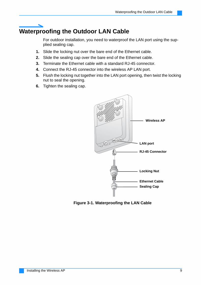
Waterproofing the Outdoor LAN CableFor outdoor installation, you need to waterproof the LAN port using the sup-plied sealing cap.
1. Slide the locking nut over the bare end of the Ethernet cable.
2. Slide the sealing cap over the bare end of the Ethernet cable.
3. Terminate the Ethernet cable with a standard RJ-45 connector.
4. Connect the RJ-45 connector into the wireless AP LAN port.
5. Flush the locking nut together into the LAN port opening, then twist the locking nut to seal the opening.
6. Tighten the sealing cap.
Figure 3-1. Waterproofing the LAN Cable
Wireless AP
RJ-45 Connector
LAN port
Locking Nut
Sealing Cap
Ethernet Cable
9Installing the Wireless AP

Hardware Installation
Hardware Installation
Mounting on a Pole
Note: Make sure that the pole for installation is securely attached to a solid, stable base.
1. Secure the mounting clip to the back of the wireless AP with four screws.
2. Slide the securing rings through the mounting bracket. Adjust the straps to make sure that the rings are securely fastened to the pole.
3. Slide the mounting clip into the slot on the mounting bracket.
4. Insert the bolt into the hole on the mounting clip the mounting bracket, and secure the end with the lock nut.
Note: Do not tighten the lock nut completely at this time, as you may need to make adjustments to obtain good signal strength.
Figure 3-2. Mounting the Wireless AP on a Pole
Mounting Clip
Wireless AP
Mounting Bracket
Securing Rings
Bolt
Lock Nut
10Installing the Wireless AP

Connecting to a Power Source
Installing Antennas
You may install optional 2.4 or 5GHz antennas on top of the wireless AP to extend the range of your wireless network.
Caution - Make sure that you disconnect the wireless AP from the power source before connecting the optional antennas.
Caution - Do not remove the metal caps if you are not installing 2.4 or 5GHz antennas.
1. Unscrew the metal caps protecting the antenna connectors.
2. Connect the antennas to the standard N-type female antenna connectors on the AP.
Figure 3-3. Installing Antennas
Connecting to a Power SourceThe wireless AP comes with a PoE injector kit for connecting to power over the Ethernet port. The wireless AP automatically turns on as soon as it is con-nected to a power source.
Caution - Use only the PoE injector that came with the wireless AP.
Caution - Make sure that the PoE injector is properly grounded.
1. Insert one end of an Ethernet cable to the P+D/OUT on the PoE injector.
2. Insert the other end to the Ethernet port on the wireless AP.
3. Insert one end of an Ethernet cable to the Data/IN port on the PoE injector.
4. Insert the other end to the assigned LAN port on the wireless AP controller.
2.4GHz AntennaConnector
5GHz AntennaConnector
5GHz AntennaConnector
2.4GHz AntennaConnector
11Installing the Wireless AP

Connecting to a Power Source
5. Connect an Ethernet cable between the wireless AP controller and the com-puter.
6. Connect a power cord to the PoE injector.
7. Connect the power plug to a wall socket.
Figure 3-4. Connecting to Power via the PoE Injector
PoE
POWER
NETWORK
Wall Socket
Power Plug
Power Cord
Ethernet Cable
Data/IN Port
Connect to PC or switch
Ethernet Port
PoE Injector
Wireless AP
AC AdapterPort
12Installing the Wireless AP

First-Time Connection and Configuration
First-Time Connection and Configuration
Connecting to a PC1. Connect one end of an RJ-45 cable to an Ethernet port on your computer.
2. Connect the other end to the LAN/PoE port on the wireless AP.
Note: Make sure all other components and hardware are properly connected and installed. Refer to “Hardware Installation” on page 10.
3. Configure the computer with a static address: 192.168.1.x, where x is any number except 0, 1, or 255.
Note: Default IP address for the LAN/PoE port: 192.168.1.1.
4. Open the Web browser and type the IP address (default:192.168.1.1) of the wireless AP into the address field. The login page opens.
Figure 3-5. Wireless AP Login Page
13Installing the Wireless AP
First-Time Connection and Configuration
Note: If the following message appears, click Continue to this website to open the Access Portal.
Figure 3-6. Security Certificate Warning
5. Enter the following default credentials.
Username: admin
Password: password
6. Click Login to enter the Access Portal main page.
7. Select preferred language from the drop-down list.
Connecting the Wireless AP to Your Network
To manage the wireless AP on-site or remotely, you need to make sure that it is on the same network as your PC.
Note: Make sure that your network LAN cable is connected to the wireless AP LAN port.
1. On the main menu on the left, click Advanced Settings.
2. Select Fat AP from the drop-down list.
3. Click Enable on Reboot, then click Apply.
4. After the wireless AP reboots, enter the Access Portal with the default creden-tials.
5. On the main menu on the left, click Basic Setup.
6. In the Basic Setup page, go to the section Configure AP as.
7. Click the radio button corresponding to Bridge.
14Installing the Wireless AP
First-Time Connection and Configuration
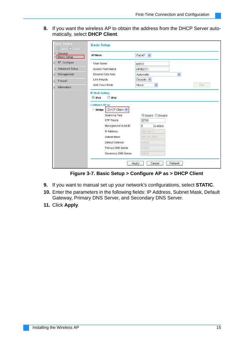
8. If you want the wireless AP to obtain the address from the DHCP Server auto-matically, select DHCP Client.
Figure 3-7. Basic Setup > Configure AP as > DHCP Client
9. If you want to manual set up your network’s configurations, select STATIC.
10. Enter the parameters in the following fields: IP Address, Subnet Mask, Default Gateway, Primary DNS Server, and Secondary DNS Server.
11. Click Apply.
15Installing the Wireless AP

First-Time Connection and Configuration
Note: Make sure that the wireless AP and your PC are in the same subnet.
Figure 3-8. Basic Setup > Configure AP as > STATIC
Changing the Default Password
The first time you log in to the Access Portal, you will be prompted to change the default password.
1. On the main menu on the left, click Management, then click Change Pass-word.
2. Enter the default password (password) and enter a new password.
3. Retype the new password in the Repeat New Password field.
4. Click Apply.
Note: Write down the new password and keep it in a safe place for retrieval if needed.
16Installing the Wireless AP

Setting Up the Access Portal
Chapter 4
Accessing the Wireless AP
Setting Up the Access PortalManage the wireless AP easily using a web browser.
1. Open the Web browser and type the IP address of the smart antenna into the address field. The login page opens.
Note: If you configured the smart antenna to your network, use the new IP address; otherwise, you may enter the default IP address: 192.168.1.1.
Figure 4-1. Wireless AP Login Page
17Accessing the Wireless AP

Navigating the Access Portal
Note: If the following message appears, click Continue to this website to open the Access Portal
Figure 4-2. Security Certificate Warning
2. Enter the username and password.
Note: The administrator may have changed the default credentials. Obtain the username and password from your administrator.
3. Select preferred language from the drop-down list.
4. Click Login to enter the Access Portal main page.
Navigating the Access PortalGet to know the Access Portal screen to manage the smart antenna easily using web browser. The screen has three main areas:
18Accessing the Wireless AP

Navigating the Access Portal
1. Quick Management Action Bar
The quick management action bar provides three useful links: Home, Help and Exit.
Figure 4-3. Quick Management Action Bar
Table 4-1. Quick Management Action Bar
Item Description
HomeReturns to the main interface, which displays general information about the wireless AP.
HelpDisplays Help information about items on the user interface menu.
Exit Logs you out of the Web Configurator.
19Accessing the Wireless AP

Navigating the Access Portal
2. Main Menu
This area contains all the configuration parameters of the wireless AP. There are seven main menus.
Figure 4-4. Default Home Page with Main Menu
Table 4-2. Main Menu
Item Description
General
Displays basic information about the wireless AP:
System Information: Shows the device model, current usage status settings of the system hardware, and the uptime of your access point.
Access Point Information: Shows general information, such as AP name, MAC address, country/region, firmware ver-sion, hardware version, bootloader version, and manage-ment VLAN ID.
Current IP Settings: Shows the current IP type, IP address, subnet mask, and default gateway.
Current Wireless Settings: These are the current wireless basic settings of your access point, including operating mode, channel/frequency, and security profiles.
20Accessing the Wireless AP

Navigating the Access Portal
Basic Setup
Lets you modify default values for basic settings, such as AP mode, user name, AP name, Ethernet data rate, link integrity and QoS class mode. You can also choose the IP mode setting and configure the AP bridge mode. Keep the default setting DHCP Cli-ent to obtain an IP address automatically from the DHCP server, or select STATIC to enter the values manually.
RF Configure For modifying wireless settings
Advanced Setup For configuring advanced parameters.
ManagementLets you manage the device by configuring remote settings, mod-ifying user password, upgrading the firmware, restoring and back-ing up the configurations, and restoring factory default settings.
Firewall For configuring firewall settings.
Information Displays information on AP activities.
Figure 4-4. Default Home Page with Main Menu
Table 4-2. Main Menu (Continued)
Item Description
21Accessing the Wireless AP

Factory Default Settings
3. Configuration WindowThis area displays the submenus for the Configuration menu.
Figure 4-5. Configuration Window
Factory Default Settings
Table 4-3. Factory Default Settings
Item Default Value
Username admin
Password password
Card Index Card1
22Accessing the Wireless AP

Factory Default Settings
Basic Settings
AP Mode Fat AP
Access Point NameAPxxxxxx (xxxxxx repre-sents the last six digits in the wireless AP MAC address)
Ethernet Data Rate Automatic
Link Integrity Disable
QoS Class Mode None
IP Mode IPv4
Nation/Region China
Configure AP as Bridge
Spanning Tree Enable
STP Priority 32768
Management VLAN ID 0
IP Settings
IP Type: DHCP Client
IP Address: 192.168.1.1
Subnet Mask: 255.255.255.0
Default Gateway: 0.0.0.0
Master/Slave DNS Server: 0.0.0.0
Table 4-3. Factory Default Settings (Continued)
Item Default Value
23Accessing the Wireless AP
Factory Default Settings
Wireless Settings
Enable Radio Yes
Country/RegionAustria (Country domain may vary)
Operating Mode AP Mode
Wireless Standard 802.11b/g/n
Basic Speed 1/2/5.5/11
Support Speed 6/9/12/18/24/36/48/54
Channel/Frequency 6/2.437GHz
Data Rate Auto
RTS Threshold 2346
Beacon Interval 100
DTIM Time Interval 1
Preamble Type Long
Channel Mode 20MHz
Short GI Yes
AMPDU Yes
AMSDU No
HT Protect No
MIMO No
Channel Protect No Protection
Output Power -0.0
Enable Auto Power No
Enable Auto Frequency Adjust
No
User Control Mode Disable
Throughput Control Mode Disable
Security Profile Settings
Security Profile VLAN ID Profile 1-8 VLAN ID: Null
Security Profile NameProfileX (X represents the profile number)
Wireless Network Name (SSID)
Wireless
Broadcast WirelessNetwork Name (SSID)
Yes
VAP Max Station Number 25
Network Authentication Open System
Data Encryption: None
Wireless Client Security Separation
Disable
Table 4-3. Factory Default Settings (Continued)
Item Default Value
24Accessing the Wireless AP

Factory Default Settings
RADIUS Settings
Authentication/Access Control RADIUS Server Configuration
Primary IP Address: 0.0.0.0
Port Number: 1812
Shared Secret: Null
Secondary IP Address: 0.0.0.0
Port Number: 1812
Shared Secret: Null
Reauthentication Time 3600
Accounting RADIUS Server Configuration
Primary IP Address: 0.0.0.0
Port Number: 1813
Shared Secret: Null
Secondary IP Address: 0.0.0.0
Port Number: 1813
Shared Secret: Null
WAPI Settings
WAPI AS IP Address 0.0.0.0
WAPI Unicast Rekey Time 86400
WAPI Multicast Rekey Time
86400
Certification Type X509
Certification Num Three Certifications
Access Control Settings
Turn Access Control On Null
Select Access Control Database
Local MAC AddressDatabase
Trust/Reject Trust
MAC Address/Throughput (Both Tx&Rx are this rate)
Null
Table 4-3. Factory Default Settings (Continued)
Item Default Value
25Accessing the Wireless AP
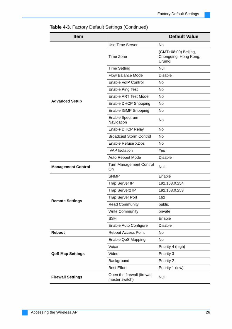
Factory Default Settings
Advanced Setup
Use Time Server No
Time Zone(GMT+08:00) Beijing, Chongqing, Hong Kong, Urumqi
Time Setting Null
Flow Balance Mode Disable
Enable VoIP Control No
Enable Ping Test No
Enable ART Test Mode No
Enable DHCP Snooping No
Enable IGMP Snooping No
Enable SpectrumNavigation
No
Enable DHCP Relay No
Broadcast Storm Control No
Enable Refuse XDos No
VAP Isolation Yes
Auto Reboot Mode Disable
Management ControlTurn Management Control On
Null
Remote Settings
SNMP Enable
Trap Server IP 192.168.0.254
Trap Server2 IP 192.168.0.253
Trap Server Port 162
Read Community public
Write Community private
SSH Enable
Enable Auto Configure Disable
Reboot Reboot Access Point No
QoS Map Settings
Enable QoS Mapping No
Voice Priority 4 (high)
Video Priority 3
Background Priority 2
Best Effort Priority 1 (low)
Firewall SettingsOpen the firewall (firewall master switch)
Null
Table 4-3. Factory Default Settings (Continued)
Item Default Value
26Accessing the Wireless AP

Factory Default Settings
IP Filter
Firewall function Close
IP address filtering function Close
The default filter rule Accept all
MAC Filter
Firewall function Close
MAC address filtering func-tion
Close
The default filter rule Accept all
SysLog Enable Syslog Null
ScanEnable Adjacent AP/STA Scan
Dedicated MODE-One-Shot
Table 4-3. Factory Default Settings (Continued)
Item Default Value
27Accessing the Wireless AP

General Menu
Chapter 5
Configuring the Wireless Access Point
General MenuOn the main menu, go to General to view information about the system and the wireless access point.
Figure 5-1. General Menu
Table 5-1. General Menu
Item Description
System InformationDisplays information about the device model, memory capacity, memory usage, CPU usage, flash usage, device temperature, AP uptime, and Ethernet port status.
28Configuring the Wireless Access Point

General Menu
Current IP Settings
When the wireless AP is operating on an existing network and providing WLAN services, changing its time will affect syslog and DHCP service and the user may have problems obtaining an IP address from the DHCP server. Take these factors into consideration when trying to change the system time.
Configuring Wireless Switch Settings
Note: Wireless Switch Settings may be configured when AP Mode is in Thin AP mode.
1. On the main menu on the left, click General.
2. Under Method of Connect with Wireless Switch, check the radio button corre-sponding to your choice.
3. To connect via IP, input the wireless switch IP address.
4. To connect via DNS, input the wireless switch name.
5. If you want the thin AP to automatically obtain the IP address, gateway, and other configuration information of the wireless switch, select Connect with Wireless Switch via DHCP.
Access Point Information
Displays the wireless AP name, MAC address, country/region, firmware version, hardware version, bootloader version, and man-agement VLAN ID
Current IP SettingsDisplays the IP type, IP address, subnet mask, and default gate-way.
Current WirelessSettings
Displays the current operating mode and channel/frequency.
Table 5-1. General Menu (Continued)
Item Description
Table 5-2. Current IP Settings
Item Description
IP Type
Shows if you enabled the wireless access point as a DHCP client, or if you manually configured the Static address. If enabled as a DHCP client, the wireless AP will automatically obtain the IP address.
IP Address Shows the current IP address.
Subnet Mask Shows the current subnet mask.
Default Gateway Shows the current values for the gateway.
29Configuring the Wireless Access Point
General Menu
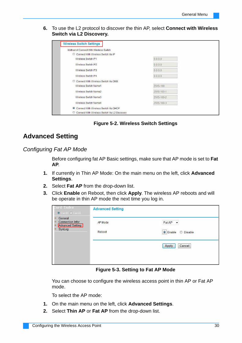
6. To use the L2 protocol to discover the thin AP, select Connect with Wireless Switch via L2 Discovery.
Figure 5-2. Wireless Switch Settings
Advanced Setting
Configuring Fat AP Mode
Before configuring fat AP Basic settings, make sure that AP mode is set to Fat AP.
1. If currently in Thin AP Mode: On the main menu on the left, click Advanced Settings.
2. Select Fat AP from the drop-down list.
3. Click Enable on Reboot, then click Apply. The wireless AP reboots and will be operate in thin AP mode the next time you log in.
Figure 5-3. Setting to Fat AP Mode
You can choose to configure the wireless access point in thin AP or Fat AP mode.
To select the AP mode:
1. On the main menu on the left, click Advanced Settings.
2. Select Thin AP or Fat AP from the drop-down list.
30Configuring the Wireless Access Point

General Menu
3. Click Enable on Reboot, then click Apply. The wireless AP reboots and will be operate in thin AP mode the next time you log in.
Figure 5-4. Selecting AP Mode
Configuring Thin AP Settings
Before configuring thin AP Basic settings, make sure that AP mode is set to Thin AP.
1. On the main menu on the left, click Advanced Settings.
2. Select Thin AP from the drop-down list.
3. Click Enable on Reboot, then click Apply. The wireless AP reboots and starts up in thin AP mode.
Figure 5-5. Setting to Thin AP Mode
Table 5-3. Advanced Setting Submenus
Item Description
AP Mode
Set the access point mode. Select between Thin AP and Fat AP.
Thin AP: A wireless switch or controller manages the wireless access point. All configurations are done on the switch or control-ler.
Fat AP: The wireless access point handles all wireless clients, and each AP has to be configured individually.
RebootEnable this option, then click Apply for all configuration changes to take effect. You will be required to log in after reboot.
31Configuring the Wireless Access Point

General Menu
Viewing the System Log
The system log page displays event log Information of the AP.
1. On the main menu on the left, click SysLog.
2. Click Refresh to update the current statistics, or click Save As to save the log information as a file.
Figure 5-6. Viewing System Log Information
32Configuring the Wireless Access Point

Basic Setup Menu
Basic Setup MenuOn the user interface menu, go to Basic Setup and configure these basic parameters.
Figure 5-7. Basic Setup Menu
Table 5-4. Basic Setup Menu
Item Description
AP Mode Select either Fat AP or Thin AP.
User Name Change the user name. The default is admin.
Access Point NameChange the access point name. The last six characters of the default name represent the last six characters of the AP MAC address.
Ethernet Data RateSet the transmission rate of the wireless AP. Lower data rates deliver stronger abilities to resist environmental interference.
Link Integrity
When enabled, the AP will disconnect the wireless terminal that has been connected and reject the wireless terminal which attempts to connect to if no LAN connection is detected.
This function must be enabled simultaneously with the Ping test functions.
QoS Class ModeChoose to apply Quality of Service (QoS) policies from available options: Dest MAC, Source MAC, VLAN ID, VLAN Priority, and Eth Type.
Configure AP AsThe AP is configured as a Bridge. Select DHCP Client to obtain an IP address from the DHCP server automatically, or select STATIC to enter the values manually.
33Configuring the Wireless Access Point

Basic Setup Menu
Configuring the AP as a Bridge
See “Configuring the WDS Settings (Bridge Mode)” on page 42.
Spanning TreeEnable or disable the Spanning Tree Protocol, which can prevent network loops and avoid broadcast storms from forming.
STP Priority Set the Spanning Tree Protocol priority number.
IP Address
If you selected STATIC under Configure AP as Bridge, you can manually configure the IP address, subnet mask, default gateway, and primary/secondary DNS. Select DHCP Client to automati-cally get the network parameters from the DHCP server.
Table 5-4. Basic Setup Menu (Continued)
Item Description
34Configuring the Wireless Access Point
RF Configure Menu
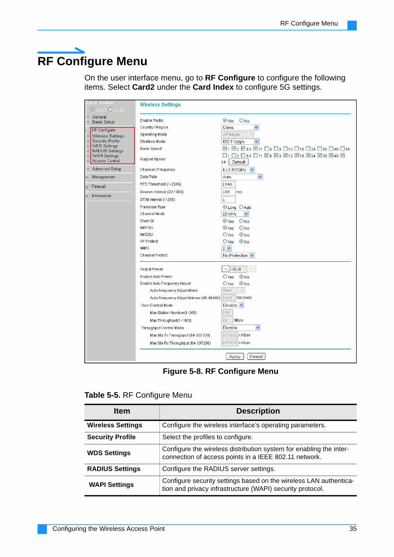
RF Configure MenuOn the user interface menu, go to RF Configure to configure the following items. Select Card2 under the Card Index to configure 5G settings.
Figure 5-8. RF Configure Menu
Table 5-5. RF Configure Menu
Item Description
Wireless Settings Configure the wireless interface’s operating parameters.
Security Profile Select the profiles to configure.
WDS SettingsConfigure the wireless distribution system for enabling the inter-connection of access points in a IEEE 802.11 network.
RADIUS Settings Configure the RADIUS server settings.
WAPI SettingsConfigure security settings based on the wireless LAN authentica-tion and privacy infrastructure (WAPI) security protocol.
35Configuring the Wireless Access Point
RF Configure Menu
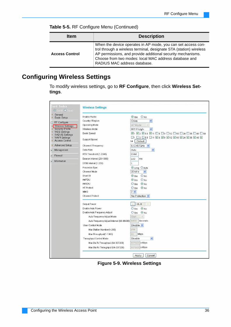
Configuring Wireless Settings
To modify wireless settings, go to RF Configure, then click Wireless Set-tings.
Figure 5-9. Wireless Settings
Access Control
When the device operates in AP mode, you can set access con-trol through a wireless terminal, designate STA (station) wireless AP permissions, and provide additional security mechanisms. Choose from two modes: local MAC address database and RADIUS MAC address database.
Table 5-5. RF Configure Menu (Continued)
Item Description
36Configuring the Wireless Access Point

RF Configure Menu
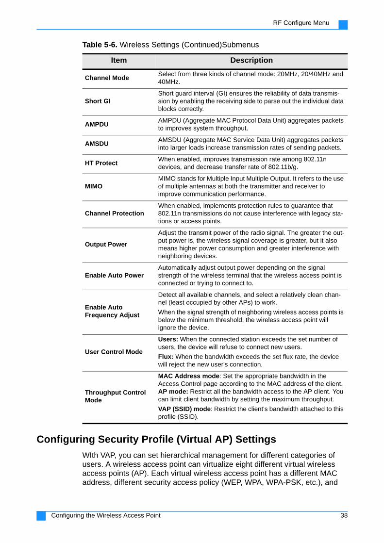
Table 5-6. Wireless Settings Submenus
Item Description
Enable Radio Select Yes to turn on the wireless function.
Country/RegionSelect your country/region from the drop-down list.
Radio frequency regulations and working channels vary in differ-ent country. Make sure to select your correct location.
Operating Mode
AP Mode establishes a wireless coverage network and allows the connection to wireless terminals.
Bridge Mode establishes a point-to-point, point-to-multipoint wireless bridge.
Note: Card 1 supports only AP mode. Card 2 supports both AP and Bridge Modes.
Wireless Mode
802.11b/g (Auto) establishes an 802.11b/g network. Both 802.11b and 802.11g wireless stations may be used. It also sup-ports wireless stations configured with 108Mbps.
802.11b only establishes an 802.11b network. 802.11g wireless terminals can still be used if they can operate in 802.11b mode.
802.11g only establishes an 802.11g network. An 802.11b wire-less terminal cannot access this network.
802.11b/g/n establishes an 802.11b/g/n network.
802.11n (2.4G) establishes an 802.11n wireless node working in 2.4G band.
Basic Speed Shows the basic radio transmit speed.
Support Speed Shows other radio transmit speeds supported.
Channel/FrequencySelect the working channel according to the frequency plan within your country/region.
Data RateSet the transmission rate. Select Auto to get the transmission rate according to the environment.
RTS Threshold
Request to Send (RTS) is used to solve network conflicts when two sites send data to the AP simultaneously. When a data packet is larger than the threshold value, the sending site notifies the AP. The AP then informs other sites to postpone data transmission, then notifies the first site to send the data.
Beacon Interval Synchronizes the wireless access point connected to the packet of wireless terminal. The effective range of beacon interval is from 20 to 1000. Recommend to use the default value.
DTIM Time IntervalSet the interval of Delivery Traffic Indication Message, which is used to inform clients of the next window for listening to broadcast and multicast information.
Preamble Type
The 802.11g standard supports Long (128 bits) and short (56 bits). The 802.11b standard only supports short.
Short preamble improves the overall utilization of the wireless channel to achieve higher priority transmission bandwidth.
Long preamble is recommended when the environment has more interference.
Set to Auto to get the optimum performance.
37Configuring the Wireless Access Point
RF Configure Menu
Configuring Security Profile (Virtual AP) Settings
WIth VAP, you can set hierarchical management for different categories of users. A wireless access point can virtualize eight different virtual wireless access points (AP). Each virtual wireless access point has a different MAC address, different security access policy (WEP, WPA, WPA-PSK, etc.), and
Channel ModeSelect from three kinds of channel mode: 20MHz, 20/40MHz and 40MHz.
Short GIShort guard interval (GI) ensures the reliability of data transmis-sion by enabling the receiving side to parse out the individual data blocks correctly.
AMPDUAMPDU (Aggregate MAC Protocol Data Unit) aggregates packets to improves system throughput.
AMSDUAMSDU (Aggregate MAC Service Data Unit) aggregates packets into larger loads increase transmission rates of sending packets.
HT ProtectWhen enabled, improves transmission rate among 802.11n devices, and decrease transfer rate of 802.11b/g.
MIMOMIMO stands for Multiple Input Multiple Output. It refers to the use of multiple antennas at both the transmitter and receiver to improve communication performance.
Channel ProtectionWhen enabled, implements protection rules to guarantee that 802.11n transmissions do not cause interference with legacy sta-tions or access points.
Output Power
Adjust the transmit power of the radio signal. The greater the out-put power is, the wireless signal coverage is greater, but it also means higher power consumption and greater interference with neighboring devices.
Enable Auto PowerAutomatically adjust output power depending on the signal strength of the wireless terminal that the wireless access point is connected or trying to connect to.
Enable AutoFrequency Adjust
Detect all available channels, and select a relatively clean chan-nel (least occupied by other APs) to work.
When the signal strength of neighboring wireless access points is below the minimum threshold, the wireless access point will ignore the device.
User Control Mode
Users: When the connected station exceeds the set number of users, the device will refuse to connect new users.
Flux: When the bandwidth exceeds the set flux rate, the device will reject the new user's connection.
Throughput Control Mode
MAC Address mode: Set the appropriate bandwidth in the Access Control page according to the MAC address of the client. AP mode: Restrict all the bandwidth access to the AP client. You can limit client bandwidth by setting the maximum throughput.
VAP (SSID) mode: Restrict the client's bandwidth attached to this profile (SSID).
Table 5-6. Wireless Settings (Continued)Submenus
Item Description
38Configuring the Wireless Access Point
RF Configure Menu
different VLAN divisions. As for the wireless terminal, there seems to exist 8 actual wireless access points.
When the wireless terminal attempts to connect to a virtual wireless access point, it first needs to support the virtual wireless access point's security pol-icy. When the wireless terminal successfully connects the virtual wireless access point, the wireless terminal will receive VLAN attributes setting consis-tent with the virtual wireless access point VLAN.
1. On the main menu on the left, click RF Configure, then click Security Pro-files.
2. Select a profile, then click Edit.
Figure 5-10. Security Profile
3. Configure the parameters in the Security Profile Configuration page that opens.
39Configuring the Wireless Access Point

RF Configure Menu
4. Click Apply.
Figure 5-11. Security Profile Configuration
Table 5-7. Security Profile Submenus
Item Description
Profile Name Displays the current profile name.
SSID Displays the current SSID associated with the profile.
Security Displays the current security system.
EnableUse this checkbox to enable or disable each security profile as required.
Security Profile VLAN ID (Profile 1-8)
Specify the VLAN ID for each profile. Only STAs associated with this profile can log into the web page and manage the device. If the AP is configured as a Bridge, you may also configure the encryption method of the wireless distribution system (WDS) here.
Table 5-8. Security Profile Configuration Submenus
Item Description
Security Profile Name Set security configuration file name for VAP management.
Wireless Network Name (SSID)
Specify a service set identification (SSID), a case-sensitive unique identifier made up of up to 32 alphanumeric characters. Devices attempting to connect to the wireless AP must use the same SSID.
Broadcast Wireless Network Name (SSID)
When the wireless AP is working in AP mode, it will periodically send out broadcast frames containing its own information, such as the wireless network name (SSID), making it vulnerable to unauthorized access.
40Configuring the Wireless Access Point

RF Configure Menu
Network Authentication
The wireless AP offers a variety of authentication methods to protect the net-work. The succeeding table lists network authentication methods.
WMM Support
Enable or disable support for Wireless Multimedia (WMM), a sub-set of the 802.11e standard that allows wireless traffic to have a range of priorities, depending on the kind of data. Time-depen-dent information, like video or audio, will have a higher priority than normal traffic. For WMM to function correctly, Wireless cli-ents must also support WMM.
Max Sta Tx Throughput Specify the maximum transmit frequency of wireless stations.
Max Sta Rx Throughput
Specify the maximum receive frequency of wireless stations.
VAP Max StationNumber
Specify the maximum number of wireless stations allowed to con-nect to your virtual access point.
NetworkAuthentication
Select the authentication method for ensuring network security
Data Encryption Select a data encryption method for protection wireless packets.
Passphrase Enter a passphrase to generate a key.
Wireless ClientSecurity Isolator
If you turn on this function, the associated wireless clients cannot communicate with one another.
Table 5-8. Security Profile Configuration Submenus (Continued)
Table 5-9. Network Authentication Methods
Item Description
Open system
Wireless devices (wireless card or wireless bridge) can connect with the virtual wireless access point without going through any authentication.To protect interaction packets between the wire-less devices and the wireless access point you can specify a data encryption method.
Shared Key
Use this authentication mode together with WEP encryption to encrypt packets exchanged between the wireless device and the virtual wireless access point, and also for the wireless access point to authenticate wireless devices attempting to connect to it.
WPA-PSK, WPA2-PSK,WPA-PSK & WPA2-PSK
No user authentication process, and no requirement of special-ized authentication server. The user's access control is mainly through the pre-set shared key encryption for wireless packets.
Encryption for wireless packet is based on the shared key. How-ever, the shared key is never used to encrypt data packets directly, but only to ensure the security of underlying key genera-tion and interaction between the wireless access point and wire-less terminals. The basic key packet serial number and other factors generate the final key, which is used to encrypt messages.
Messages are encrypted in the following ways: TKIP (WPA-PSK), AES (WPA2-PSK), TKIP & AES (WPA-PSK & WPA2-PSK).
These methods are suitable for networks within small and medium enterprises or homes.
41Configuring the Wireless Access Point

RF Configure Menu
Data Encryption
Protect wireless packets going through the network. You will need to enter a key, and other wireless devices (terminal or bridge) must use the same key to communicate.
Configuring the WDS Settings (Bridge Mode)
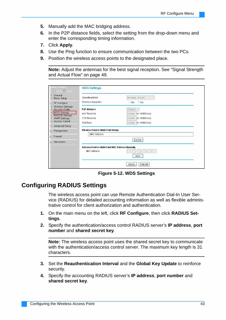
The wireless AP can work as a bridge to connect two or more networks that are separated physically or by protocol. Point-to-point bridging is enabled with wireless bridge devices working in pairs, while point-to-multipoint bridging uses one device to centrally connect other devices simultaneously.
Note: This function is only available in 5G radio.
The wireless access points are built through a wireless distribution system (WDS).
1. Connect two wireless devices to power.
2. Connect both devices to the PC using Ethernet cables.
3. On the main menu on the left, click RF Configure > WDS Settings and select Card2.
4. Input the distance between the devices on the wireless range.
Note: For point-to-multi-point bridging, the distance is from the farthest point to the center.
WAPI-PSK & WAPI Certificate
WAPI stands for Wireless LAN Authentication and Privacy Infra-structure, a wireless LAN (WLAN) security protocol and security mechanism of Chinese mandatory standards in wireless LAN. WAPI uses certificate authentication mode, and can work only with the authentication server.
Table 5-9. Network Authentication Methods (Continued)
Item Description
Table 5-10. Data Encryption Methods
Item Description
NoneCan only be used if the network authentication type is Open Sys-tem.
64 bits WEPStandard WEP encryption, using 40/64 bit encryption made up of 10 hex numbers.
128 bits WEPStandard WEP encryption, using 104/128 bit encryption made up of 26 hex numbers.
152 bits WEPStandard WEP encryption, using 104/128 bit encryption made up of 32 hex numbers. This is a proprietary mode that will only work with other wireless devices supporting this mode.
42Configuring the Wireless Access Point
RF Configure Menu
5. Manually add the MAC bridging address.
6. In the P2P distance fields, select the setting from the drop-down menu and enter the corresponding timing information.
7. Click Apply.
8. Use the Ping function to ensure communication between the two PCs.
9. Position the wireless access points to the designated place.
Note: Adjust the antennas for the best signal reception. See “Signal Strength and Actual Flow” on page 49.
Figure 5-12. WDS Settings
Configuring RADIUS Settings
The wireless access point can use Remote Authentication Dial-In User Ser-vice (RADIUS) for detailed accounting information as well as flexible adminis-trative control for client authorization and authentication.
1. On the main menu on the left, click RF Configure, then click RADIUS Set-tings.
2. Specify the authentication/access control RADIUS server’s IP address, port number and shared secret key.
Note: The wireless access point uses the shared secret key to communicate with the authentication/access control server. The maximum key length is 31 characters.
3. Set the Reauthentication Interval and the Global Key Update to reinforce security.
4. Specify the accounting RADIUS server’s IP address, port number and shared secret key.
43Configuring the Wireless Access Point
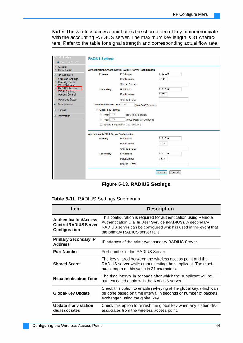
RF Configure Menu
Note: The wireless access point uses the shared secret key to communicate with the accounting RADIUS server. The maximum key length is 31 charac-ters. Refer to the table for signal strength and corresponding actual flow rate.
Figure 5-13. RADIUS Settings
Table 5-11. RADIUS Settings Submenus
Item Description
Authentication/Access Control RADIUS Server Configuration
This configuration is required for authentication using Remote Authentication Dial In User Service (RADIUS). A secondary RADIUS server can be configured which is used in the event that the primary RADIUS server fails.
Primary/Secondary IP Address
IP address of the primary/secondary RADIUS Server.
Port Number Port number of the RADIUS Server.
Shared SecretThe key shared between the wireless access point and the RADIUS server while authenticating the supplicant. The maxi-mum length of this value is 31 characters.
Reauthentication Time The time interval in seconds after which the supplicant will be authenticated again with the RADIUS server.
Global-Key UpdateCheck this option to enable re-keying of the global key, which can be done based on time interval in seconds or number of packets exchanged using the global key.
Update if any station disassociates
Check this option to refresh the global key when any station dis-associates from the wireless access point.
44Configuring the Wireless Access Point

RF Configure Menu
Accounting RADIUS Server Configuration
This configuration is required for accounting using RADusing Remote Authentication Dial In User Service (RADIUS). A sec-ondary RADIUS server can be configured which is used in the event that the primary RADIUS server fails.
IP Address IP address of the RADIUS server.
Port Number Port number of the RADIUS server.
Shared SecretThe key shared between the wireless access point and the RADIUS server while authenticating the supplicant. The maxi-mum length of this value is 31 characters.
Table 5-11. RADIUS Settings Submenus (Continued)
45Configuring the Wireless Access Point
RF Configure Menu
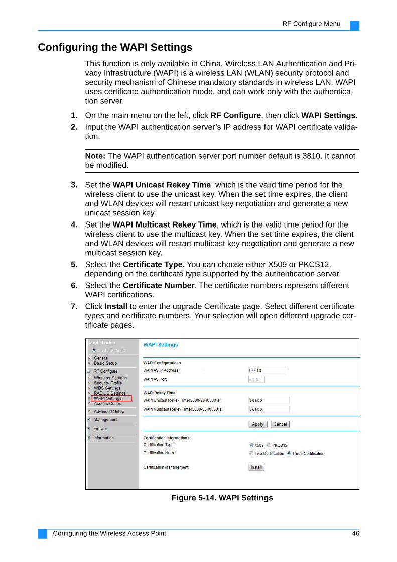
Configuring the WAPI Settings
This function is only available in China. Wireless LAN Authentication and Pri-vacy Infrastructure (WAPI) is a wireless LAN (WLAN) security protocol and security mechanism of Chinese mandatory standards in wireless LAN. WAPI uses certificate authentication mode, and can work only with the authentica-tion server.
1. On the main menu on the left, click RF Configure, then click WAPI Settings.
2. Input the WAPI authentication server’s IP address for WAPI certificate valida-tion.
Note: The WAPI authentication server port number default is 3810. It cannot be modified.
3. Set the WAPI Unicast Rekey Time, which is the valid time period for the wireless client to use the unicast key. When the set time expires, the client and WLAN devices will restart unicast key negotiation and generate a new unicast session key.
4. Set the WAPI Multicast Rekey Time, which is the valid time period for the wireless client to use the multicast key. When the set time expires, the client and WLAN devices will restart multicast key negotiation and generate a new multicast session key.
5. Select the Certificate Type. You can choose either X509 or PKCS12, depending on the certificate type supported by the authentication server.
6. Select the Certificate Number. The certificate numbers represent different WAPI certifications.
7. Click Install to enter the upgrade Certificate page. Select different certificate types and certificate numbers. Your selection will open different upgrade cer-tificate pages.
Figure 5-14. WAPI Settings
46Configuring the Wireless Access Point
RF Configure Menu
Configuring Access Control
If the wireless access point is operating in AP mode, you can configure access control through a wireless terminal, designate STA wireless access points access permissions and provide additional layer of security mecha-nisms. There are two modes: local MAC address database and RADIUS MAC address database.
1. On the main menu on the left, click RF Configure, then click Access Control.
2. Check the box corresponding to Turn Access Control On.
3. From the drop-down list next to Select Access Control Database, choose the access control mode.
4. If you selected Local MAC Address Database, choose from available wireless stations, or manually add a wireless station to trust or reject.
Table 5-12. WAPI Settings Submenus
Item Description
WAPI AS IP Address IP address of the WAPI authentication server.
WAPI AS Port Port number of the WAPI authentication server.
WAPI Unicast Rekey Time
The valid time period for the wireless client to use the unicast key. When the set time expires, the client and WLAN devices will restart unicast key negotiation and generate a new unicast ses-sion key.
WAPI Multicast Rekey Time
The valid time period for the wireless client to use the multicast key. When the set time expires, the client and WLAN devices will restart multicast key negotiation and generate a new multicast session key
Certification Type Choose either X509 or PKCS12, depending on the certificate type supported by the authentication server
Certification NumCertificate numbers represent different WAPI authentication modes.
CertificationManagement
Click Install to upgrade the certification. You will be prompted to browse and upload the required certificates: Certificate Authenti-cation (CA), Access Point (AP), and AS (Authentication Server).
47Configuring the Wireless Access Point

RF Configure Menu
5. If you selected RADIUS MAC Address Database, the wireless AP will use the MAC address list on the RADIUS server. Input the RADIUS server name and password of the wireless client’s wireless card.
Figure 5-15. Access Control
Table 5-13. Access Control Submenus
Item Description
Turn Access Control On
Enable or disable the access control function.
Select Access Control Database
The access point will use the local MAC address table for access control.
Trusted (or Rejected) Wireless Stations / Throughput
Lists wireless stations/throughput you have entered. If you have not entered any wireless stations this list will be empty. To delete an existing entry, select it and then click the Delete button.
Available WirelessStations
Select the stations from the wireless station list and click the Add button to add to the Trusted (or Rejected) Wireless Stations list.
Add new Station/Throughput Manually
Input the MAC address of the wireless stations you want to add to the Trusted (or Rejected) Wireless Stations list.
48Configuring the Wireless Access Point

Advanced Setup
Advanced SetupOn the user interface menu, go to Advanced Setup to configure advanced settings.
Figure 5-16. Advanced Setup Menu
49Configuring the Wireless Access Point

Advanced Setup
Table 5-14. Advanced Setup Menu
Item Description
Device Time Setting
When Use Time Server is set to Yes, the device can be set to get the time from the time server. In this section, you can also choose the time zone of your country/region, adjust for daylight savings time, and set the date and time yourself.
Flow Balance ModeDisable or choose the flow balance mode to increase network sta-bility. You can choose flow balance based on the number of users, flow of data, or dynamic balancing.
Enable VoIP ControlSetting the maximum number of Voice Over Internet Protocol (VoIP) sessions allowed based on IP addresses.
Enable Ping Test
If this item is enabled, you may set the destination IP address to test. If you set Enable Reboot to Yes and ping times out within about 6 minutes, the device will reboot; if you set it to No, the device will set a ping packet every 1 minute.
Enable ART Test Mode
Enable or disable the Atheros Radio Test (ART).
Enable DHCPSnooping
If this item is enabled, multicast data will be sent to the VAP that needs to be sent on to replace the original broadcasts.
Enable IGMPSnooping
If this item is enabled, unicast data is sent to the suitable VAP that needs this multicast data, and then replace the broadcast. This function may be used only in AP mode.
Enable Spectrum Navigation
Allows the STA preferential use of 5GHz to access the network, thus improving the user experience.
Enable DHCP RelayThis function works in Router mode. When this item is enabled, the wireless terminal client can obtain an IP address from a DHCP server on the WAN side.
IGMP Proxy ModeDisable or specify the upstream and downstream interfaces to use the Internet Group Management Protocol (IGMP) Proxy Mode. This function may only be used in Router mode.
Broadcast Storm Control
Allow the port to filter broadcast storms on the network.Allow the port to filter broadcast storms on the network.
Enable Refuse XDos Enable this item to prevent XDox attacks.
VAP Isolation If this item is enabled, the AP blocks communication between wireless clients on the same virtual access point.
Auto Reboot ModeIf this item is enabled, the device can be set to automatically restart on a periodic basis, depending on your selection of hours or days.
50Configuring the Wireless Access Point

Management Settings
Management SettingsOn the user interface menu, go to Management to configure the following items.
Figure 5-17. Management Menu
Configuring Management Control
Manage the wireless access point using the Management Control page. Here, you can specify IP addresses to block or allow.
1. On the main menu on the left, go to Management, then click Management Ctrl.
Table 5-15. Management Menu
Item Description
Management ControlBlock or allow the network access privilege of the specified stations or PC to manage the wireless access point.
Remote SettingsConfigure SNMP and SSH, enable or disable Auto Configure.
Change PasswordChange the password or revert to the default pass-word (password).
Upgrade Firmware Install a new version of the software.
Backup/RestoreBack up current settings, retrieve backup settings from a file, and restore the factory default settings.
PingTest the network connection of the wireless access point.
Reboot Reboot the wireless access point.
QoS Map Set traffic priorities.
51Configuring the Wireless Access Point

Management Settings
2. Click the checkbox next to Turn Management Control On to enable this fea-ture.
3. Select whether to allow or deny the IP addresses you will specify.
4. Under Add New Address, input the IP address you want to block or allow.
5. Click Apply. The new IP address appears in the IP Address List.
6. Repeat steps 4 and 5 to add more IP addresses.
Figure 5-18. Management Control
Table 5-16. Management Control Submenus
Item Description
Turn Management Control On
Click the check box to enable management control.
Mode Choose whether to allow or block the IP address.
IP Address List Shows the IP addresses you chose to block or allow.
New IP Address Input the IP address you want to block or allow.
52Configuring the Wireless Access Point

Management Settings
Configuring Remote Settings
Manage the wireless access point remotely through simple network manage-ment protocol (SNMP), secure shell (SSH), auto configuration, and system logs.
Figure 5-19. Remote Settings
Table 5-17. Remote Settings Submenus
Item Description
SNMPEnable or disable remote management via Simple Network Management Protocol (SNMP).
Trap Server IPInput the IP address of the trap server for receiving log messages.
Trap Server Port Input the trap server port number
Read Community Set a password for read information.
Write Community Set a password for write information.
ApplyClick Apply to confirm that you want the new set-tings to take effect.
CancelClick Cancel to disregard changes and revert to pre-vious settings.
SSHEnable or disable remote management via Secure Shell (SSH).
Enable Auto ConfigureEnable or disable automatic configuration of remote settings.
ApplyClick Apply to confirm that you want the new set-tings to take effect.
CancelClick Cancel to disregard changes and revert to pre-vious settings.
53Configuring the Wireless Access Point

Management Settings
Configuring the AP via SNMP
Note: If you use the management information base (MIB) to manage the wire-less access point, you must set the SNMP parameters and obtain the MIB file.
To obtain the MIB file (assuming device IP is the default 192.168.1.1):
1. Open a command prompt window, then enter the command ftp: 192.168.1.1.
2. When prompted, enter the device login user name and password.
3. After successful login, enter the command get zn7100.mib.
4. In the command prompt window in the current directory, obtain the MIB file.
MIB management parameters are as follows:
1. Trap Server IP Address: Trap Server (Trap server) IP address.
2. Trap Server Port: Specify the Trap Server port number. Default value is 162.
3. Read Community Password: Read MIB node information. If set to Private, a password is required.
4. Set Write Community Password: Set the MIB node information. If set to Pri-vate, a password is required.
Configuring the AP via SSH
Note: To configure the AP using security shell (SSH) management device, we recommend that you use the Putty software registry.
1. Launch the Puttysoftware
2. Enter the IP address of the device, and select SSH as protocol.
54Configuring the Wireless Access Point

Management Settings
3. For connection type, select SSH.
Figure 5-20. PuTTY Main Interface
55Configuring the Wireless Access Point

Management Settings
4. Under Encryption cipher selection policy options, select 3DES.
Figure 5-21. PuTTY Configuration
5. Click Open. The following screen opens.
Figure 5-22. SSH Terminal Settings
6. Enter the device's user name and password. You can log in after entering the settings.
Configuring the AP via Automatic Configuration
When this feature is enabled, you need to input the correct server IP address, user name, password, and specify the file name. When the device is powered on, or meets the configured interval period, the device automatically down-loads the specified file from the server and configures the device.
56Configuring the Wireless Access Point

Management Settings
Changing the Password
Prevent unauthorized access to the wireless AP by changing the default pass-word after your first login, and periodically changing passwords.
1. On the main menu on the left, click Management, then click Change Pass-word.
2. Enter the default password (password), and enter a new password.
3. Retype the new password in the Repeat New Password field.
4. Click Apply.
5. The access portal will require you to enter the new password the next time you log in.
Figure 5-23. Changing the Password
Restoring the Default Password 1. On the main menu on the left, click Management, then click Change Pass-
word.
2. Enter the current password.
3. At Restore Default Password, click the radio button next to Yes.
4. Click Apply. The Access Portal will require you to enter the default password (password) the next time you log in.
Upgrading Firmware1. Download the latest firmware from the company’s support site.
2. Go to Management, then click Upgrade Firmware.
3. Click Browse to select the firmware file you downloaded.
4. Click Upload. Firmware update starts.
Caution - Do not unzip the firmware file.
57Configuring the Wireless Access Point
Management Settings
Caution - Do not interrupt the firmware upgrade process. Do not turn off or unplug the wireless AP, shut down the computer, or attempt to go online until the upgrade process is done.
5. Go to General to verify that the new firmware has been installed successfully.
Figure 5-24. Firmware Upgrade
Configuring Backup/Restore Settings 1. Go to Management, then click Backup/Restore.
2. To back up a copy of the current settings to a file, click Backup.
3. The Web browser will prompt you to either open or save the file.
4. To retrieve the backed up settings from a file, click Browse and locate the file.
5. Click Retrieve. A window appears, informing you that the access point has been restored to previous settings. The access point will then restart.
Caution - Do not go online, turn off the access point, shut down the computer or do anything else to the access point until it finishes restarting! When the LED turns off, wait a few more seconds before doing anything with the access point.
58Configuring the Wireless Access Point

Management Settings
Figure 5-25. Backup/Restore
Table 5-18. Backup/Restore Submenus
Item Description
Backup a copy of the current settings to a file
Create a backup file of the current settings.
Note: If your web browser is set up to save downloaded files automatically, the file is saved to the browser's download location on the hard disk.
Retrieve backed up settings from a file
Restore settings from a backup file.
59Configuring the Wireless Access Point
Management Settings
Restoring Factory Default Settings
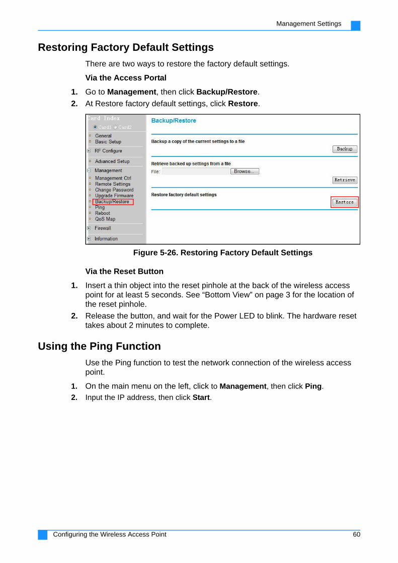
There are two ways to restore the factory default settings.
Via the Access Portal
1. Go to Management, then click Backup/Restore.
2. At Restore factory default settings, click Restore.
Figure 5-26. Restoring Factory Default Settings
Via the Reset Button
1. Insert a thin object into the reset pinhole at the back of the wireless access point for at least 5 seconds. See “Bottom View” on page 3 for the location of the reset pinhole.
2. Release the button, and wait for the Power LED to blink. The hardware reset takes about 2 minutes to complete.
Using the Ping Function
Use the Ping function to test the network connection of the wireless access point.
1. On the main menu on the left, click to Management, then click Ping.
2. Input the IP address, then click Start.
60Configuring the Wireless Access Point

Management Settings
3. Results will be displayed in the text box.
Figure 5-27. Ping
Rebooting the Wireless AP
You may need to reboot the wireless AP after making configuration changes. Sometimes, a reboot may be necessary to prevent a more serious problem or to keep the network online.
1. On the main menu on the left, go to Management, then click Reboot.
2. On the radio button next to Reboot Access Point, click Yes.
3. Click Apply.
Figure 5-28. Reboot
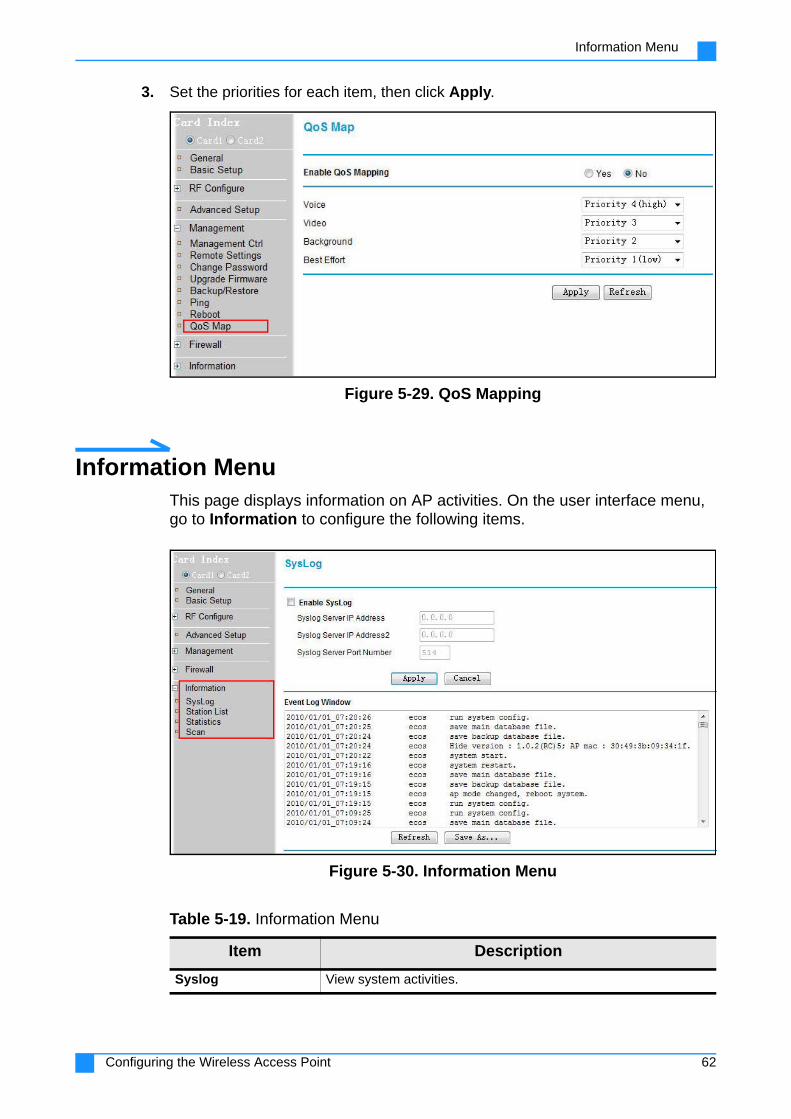
Configuring QoS Mapping
QoS mapping allows you to set traffic priorities.
1. On the main menu on the left, click to Management, then click QoS Map.
2. Click Yes to enable QoS Mapping, or No to disable it.
61Configuring the Wireless Access Point
Information Menu
3. Set the priorities for each item, then click Apply.
Figure 5-29. QoS Mapping
Information MenuThis page displays information on AP activities. On the user interface menu, go to Information to configure the following items.
Figure 5-30. Information Menu
Table 5-19. Information Menu
Item Description
Syslog View system activities.
62Configuring the Wireless Access Point

Information Menu
Station ListView the table containing all devices associated with the wireless access point for the wired network name (SSID).
Statistics View information about wired and wireless port traffic.
Scan
Allows you to scan adjacent APs or wireless stations (STAs). There are two modes to choose from:
Dedicated MODE-One-Shot: Scan all available channels at one time. Information on detected wireless access points and wireless terminals show up in the list.
Dedicated MODE-Continuous: Continuously scan all chan-nels available. Information on detected wireless access points and wireless terminals show up in the list.
Table 5-19. Information Menu
Item Description
63Configuring the Wireless Access Point

Information Menu
Checking System Logs
System logs allow provide a preview of system activities, such as STA con-nection and disconnection as well as authentication successes and failures. The information is helpful for computer system and network management, as well as for security auditing.
To view system logs:
1. Go to Information, then click Syslog.
2. Enable Syslog if you want the wireless AP to log system activities.
3. Input the Syslog Server IP Address and Syslog Server Port Number.
4. Click Apply.
5. Click Refresh to update the information.
6. Click Save As... to save the log information.
Figure 5-31. System Log
Table 5-20. Syslog Submenus
Item Description
Enable Syslog Click the box to enable syslog.
Syslog Server IP Address / Address2
Input the IP address of the syslog server.
Syslog Server Port Number
Specify the syslog port number registered with the Internet Assigned Numbers Authority (IANA). Official assignments of port numbers are for specific uses. The port number “514”, for exam-ple, is specifically assigned for system logging.
ApplyClick Apply to confirm that you want the new settings to take effect.
CancelClick Cancel to disregard changes and revert to previous set-tings.
64Configuring the Wireless Access Point

Information Menu
Checking the Station List
The station list contains all devices associated with the wireless access point for the wired network name (SSID).
To view the station list:
1. Go to Information, then click Station List.
For each device, you will see the station ID, MAC address, IP address, RSSID, Status (if the device is allowed to communicate with the wireless access point), and other information.
2. Click Refresh to update the information.
Figure 5-32. Station List
Checking the Statistics
The Statistics page displays information about wired and wireless port traffic.
To view the station list:
1. Go to Information, then click Statistics.
You can view traffic information about each wired and wireless port.
2. Click Refresh to update the information.
Figure 5-33. Statistics
65Configuring the Wireless Access Point

Information Menu
Scanning Adjacent APs/STAs
Use the Scan function to detect adjacent APs or wireless stations (STAs).
To use the Scan function:
1. Go to Information, then click Scan.
2. Select the type of scan you want to perform, then click Apply.
3. Click Scan to start scanning. Information on detected APs and STAs will appear in the list.
Figure 5-34. Scan
Table 5-21. Statistics Submenus
Item Description
Wired Ethernet Displays statistics for the wired Ethernet interface.
Wireless Displays statistics for the wireless interface.
Refresh Click Refresh to update the display.
66Configuring the Wireless Access Point