z21 lan protocol specification...z21 lan protocol specification document version 1.09 en 23.05.2019...
TRANSCRIPT

Z21 LAN Protocol Specification
Document Version 1.09 en 23.05.2019 1/54
Z21 LAN Protocol Specification

Z21 LAN Protocol Specification
Document Version 1.09 en 23.05.2019 2/54
Legal notices, exclusion of liability
Modelleisenbahn GmbH expressly states that it shall under no circumstances be legally liable for the content in this document or for any additional information specified in this document. The legal responsibility exclusively lies with the user of the data provided or with the publisher of the additional information in question. The company Modelleisenbahn GmbH (of Plainbachstrasse 4, A-5101 Bergheim, Austria) expressly accepts no liability for any and all damages caused by the use or by the non-use of the information provided. Modelleisenbahn GmbH, Plainbachstrasse 4, A-5101 Bergheim, Austria, accepts no responsibility for the up-to-dateness, correctness, completeness or quality of the information provided. No liability claims relating to damages of a material, immaterial or conceptual nature due to the use or non-use of the information shall be accepted. Modelleisenbahn GmbH, Plainbachstrasse 4, A-5101 Bergheim, Austria, reserves the right to modify, supplement or delete the information provided without prior notice. All brand names and trademarks mentioned in the document and where applicable protected by third parties, are subject without restriction to the provisions of the applicable trademark law and the ownership rights of the respective registered owners. The copyright for published information provided by Modelleisenbahn GmbH, Plainbachstrasse 4, A-5101 Bergheim, Austria remains with Modelleisenbahn GmbH, Plainbachstrasse 4, A-5101 Bergheim, Austria. Reproduction or use of the information provided in other electronic or printed publications is not permitted without express permission. Should parts or individual formulations of the liability disclaimer not, no longer or not completely comply with the applicable legal position, the remaining parts of the disclaimer remain unaffected in their content and validity.
Publishing info
Apple, iPad, iPhone, iOS are trademarks of Apple Inc., registered in the U.S. and other countries. App Store is a service mark of Apple Inc. Android is a trademark of Google Inc. Google Play is a service mark of Google Inc. RailCom is a registered trademark of the company Lenz Elektronik GmbH. Motorola is a registered trademark of Motorola Inc., Tempe-Phoenix, USA LocoNet is a registered trademark of Digitrax, Inc. All rights reserved; errors, omissions and delivery options excepted. Specifications and illustrations subject to amendment. Subject to alteration. Publisher: Modelleisenbahn GmbH, Plainbachstrasse 4, A-5101 Bergheim, Austria
Z21 LAN Protocol Specification
Document Version 1.09 en 23.05.2019 3/54
Revision history
Date Document version Change
06.02.2013 1.00 Description of LAN interface for Z21 FW Version 1.10, 1.11 and SmartRail FW Version 1.12
20.03.2013 1.01 Z21 FW Version 1.20 LAN_SET_BROADCASTFLAGS: new Flags LAN_GET_HWINFO: new command LAN_SET_TURNOUTMODE: MM format LocoNet: Gateway functionality SmartRail FW Version 1.13 LAN_GET_HWINFO: new command
29.10.2013 1.02 Z21 FW Version 1.22: Reading and writing Decoder CVs POM Read and Accessory Decoder: new commands LocoNet Dispatch and Track Occupancy Detector LAN_LOCONET_DISPATCH_ADDR: new Reply LAN_SET_BROADCASTFLAGS: new Flags LAN_LOCONET_DETECTOR: new message
12.02.2014 1.03 Z21 FW Version 1.23 Correction of long vehicle address in Chapter 4 Driving LAN_X_MM_WRITE_BYTE LAN_LOCONET_DETECTOR: Extension for LISSY
25.03.2014 1.04 Z21 FW Version 1.24 LAN_SET_BROADCASTFLAGS: Flag 0x00010000 Chapter 5 Switching: Explanation Turnout addressing LAN_X_GET_TURNOUT_INFO: Queue-Bit Extension LAN_X_DCC_WRITE_REGISTER
21.01.2015 1.05 Z21 FW Version 1.25 und 1.26 Chapter 4 Driving: Explanations about speed steps and format LAN_X_DCC_READ_REGISTER LAN_X_DCC_WRITE_REGISTER LAN_LOCONET_Z21_TX Binary State Control Instruction
05.04.2016 1.06 Z21 FW Version 1.28 Chapter 2 System Status Versions: z21start LAN_GET_HW_INFO LAN_GET_CODE
19.04.2017 1.07 Z21 FW Version 1.29 und 1.30 Chapter 8 RailCom Chapter 10 CAN
15.01.2018 1.08 Chapter 9 LocoNet : Lissy Examples
23.05.2019 1.09 en First english edition Chapter 4 Driving: added speed step coding infos Chapter 7 R-BUS: added 10808 and 10819 Chapter 9.3.1 fixed Binary State Control Instruction

Z21 LAN Protocol Specification
Document Version 1.09 en 23.05.2019 4/54
Table of contents
1 BASICS ................................................................................................................................................. 7
1.1 Communication ............................................................................................................................................... 7
1.2 Z21 Dataset ...................................................................................................................................................... 7 1.2.1 Structure .................................................................................................................................................... 7 1.2.2 X-BUS Protocol tunneling ........................................................................................................................ 8 1.2.3 LocoNet tunneling ..................................................................................................................................... 8
1.3 Combining datasets in one UDP packet ........................................................................................................ 9
2 SYSTEM, STATUS, VERSIONS ........................................................................................................ 10
2.1 LAN_GET_SERIAL_NUMBER ................................................................................................................. 10
2.2 LAN_LOGOFF ............................................................................................................................................. 10
2.3 LAN_X_GET_VERSION ............................................................................................................................. 10
2.4 LAN_X_GET_STATUS ............................................................................................................................... 11
2.5 LAN_X_SET_TRACK_POWER_OFF ....................................................................................................... 11
2.6 LAN_X_SET_TRACK_POWER_ON......................................................................................................... 11
2.7 LAN_X_BC_TRACK_POWER_OFF......................................................................................................... 12
2.8 LAN_X_BC_TRACK_POWER_ON........................................................................................................... 12
2.9 LAN_X_BC_PROGRAMMING_MODE ................................................................................................... 12
2.10 LAN_X_BC_TRACK_SHORT_CIRCUIT ................................................................................................ 12
2.11 LAN_X_UNKNOWN_COMMAND ............................................................................................................ 13
2.12 LAN_X_STATUS_CHANGED.................................................................................................................... 13
2.13 LAN_X_SET_STOP ..................................................................................................................................... 14
2.14 LAN_X_BC_STOPPED ............................................................................................................................... 14
2.15 LAN_X_GET_FIRMWARE_VERSION .................................................................................................... 14
2.16 LAN_SET_BROADCASTFLAGS .............................................................................................................. 15
2.17 LAN_GET_BROADCASTFLAGS .............................................................................................................. 16
2.18 LAN_SYSTEMSTATE_DATACHANGED ............................................................................................... 16
2.19 LAN_SYSTEMSTATE_GETDATA ........................................................................................................... 17
2.20 LAN_GET_HWINFO ................................................................................................................................... 17

Z21 LAN Protocol Specification
Document Version 1.09 en 23.05.2019 5/54
2.21 LAN_GET_CODE ........................................................................................................................................ 18
3 SETTINGS .......................................................................................................................................... 19
3.1 LAN_GET_LOCOMODE ............................................................................................................................ 19
3.2 LAN_SET_LOCOMODE ............................................................................................................................. 19
3.3 LAN_GET_TURNOUTMODE.................................................................................................................... 20
3.4 LAN_SET_TURNOUTMODE .................................................................................................................... 20
4 DRIVING ............................................................................................................................................. 21
4.1 LAN_X_GET_LOCO_INFO ....................................................................................................................... 21
4.2 LAN_X_SET_LOCO_DRIVE ..................................................................................................................... 22
4.3 LAN_X_SET_LOCO_FUNCTION ............................................................................................................. 23
4.4 LAN_X_LOCO_INFO .................................................................................................................................. 24
5 SWITCHING ........................................................................................................................................ 25
5.1 LAN_X_GET_TURNOUT_INFO ............................................................................................................... 26
5.2 LAN_X_SET_TURNOUT ............................................................................................................................ 26 5.2.1 LAN_X_SET_TURNOUT with Q=0 ..................................................................................................... 26 5.2.2 LAN_X_SET_TURNOUT with Q=1 ..................................................................................................... 28
5.3 LAN_X_TURNOUT_INFO.......................................................................................................................... 29
6 READING AND WRITING DECODER CVS ....................................................................................... 30
6.1 LAN_X_CV_READ ...................................................................................................................................... 30
6.2 LAN_X_CV_WRITE .................................................................................................................................... 30
6.3 LAN_X_CV_NACK_SC ............................................................................................................................... 30
6.4 LAN_X_CV_NACK ...................................................................................................................................... 31
6.5 LAN_X_CV_RESULT .................................................................................................................................. 31
6.6 LAN_X_CV_POM_WRITE_BYTE ............................................................................................................ 32
6.7 LAN_X_CV_POM_WRITE_BIT ................................................................................................................ 32
6.8 LAN_X_CV_POM_READ_BYTE .............................................................................................................. 33
6.9 LAN_X_CV_POM_ACCESSORY_WRITE_BYTE ................................................................................. 34
6.10 LAN_X_CV_POM_ ACCESSORY_WRITE_BIT .................................................................................... 34
6.11 LAN_X_CV_POM_ ACCESSORY_READ_BYTE ................................................................................... 35

Z21 LAN Protocol Specification
Document Version 1.09 en 23.05.2019 6/54
6.12 LAN_X_MM_WRITE_BYTE ..................................................................................................................... 36
6.13 LAN_X_DCC_READ_REGISTER ............................................................................................................. 37
6.14 LAN_X_DCC_WRITE_REGISTER........................................................................................................... 37
7 FEEDBACK – R-BUS ......................................................................................................................... 38
7.1 LAN_RMBUS_DATACHANGED .............................................................................................................. 38
7.2 LAN_RMBUS_GETDATA .......................................................................................................................... 38
7.3 LAN_RMBUS_PROGRAMMODULE ....................................................................................................... 39
8 RAILCOM ............................................................................................................................................ 40
8.1 LAN_RAILCOM_DATACHANGED ......................................................................................................... 40
8.2 LAN_RAILCOM_GETDATA ..................................................................................................................... 41
9 LOCONET ........................................................................................................................................... 42
9.1 LAN_LOCONET_Z21_RX .......................................................................................................................... 43
9.2 LAN_LOCONET_Z21_TX .......................................................................................................................... 43
9.3 LAN_LOCONET_FROM_LAN .................................................................................................................. 43 9.3.1 DCC Binary State Control Instruction .................................................................................................... 44
9.4 LAN_LOCONET_DISPATCH_ADDR ...................................................................................................... 44
9.5 LAN_LOCONET_DETECTOR .................................................................................................................. 46
10 CAN ................................................................................................................................................. 50
10.1 LAN_CAN_DETECTOR ............................................................................................................................. 50
APPENDIX A – COMMAND OVERVIEW .................................................................................................. 52
Client to Z21 .............................................................................................................................................................. 52
Z21 to Client .............................................................................................................................................................. 53
LIST OF FIGURES ..................................................................................................................................... 54
LIST OF TABLES ...................................................................................................................................... 54
Z21 LAN Protocol Specification
Document Version 1.09 en 23.05.2019 7/54
1 Basics
1.1 Communication
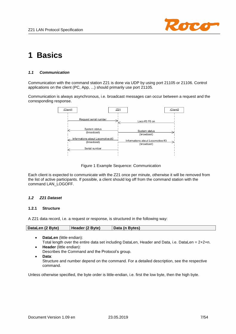
Communication with the command station Z21 is done via UDP by using port 21105 or 21106. Control applications on the client (PC, App, ...) should primarily use port 21105. Communication is always asynchronous, i.e. broadcast messages can occur between a request and the corresponding response.
Figure 1 Example Sequence: Communication
Each client is expected to communicate with the Z21 once per minute, otherwise it will be removed from the list of active participants. If possible, a client should log off from the command station with the command LAN_LOGOFF.
1.2 Z21 Dataset
1.2.1 Structure
A Z21 data record, i.e. a request or response, is structured in the following way:
DataLen (2 Byte) Header (2 Byte) Data (n Bytes)
DataLen (little endian): Total length over the entire data set including DataLen, Header and Data, i.e. DataLen = 2+2+n.
Header (little endian): Describes the Command and the Protocol’s group.
Data: Structure and number depend on the command. For a detailed description, see the respective command.
Unless otherwise specified, the byte order is little-endian, i.e. first the low byte, then the high byte.
Z21 LAN Protocol Specification
Document Version 1.09 en 23.05.2019 8/54
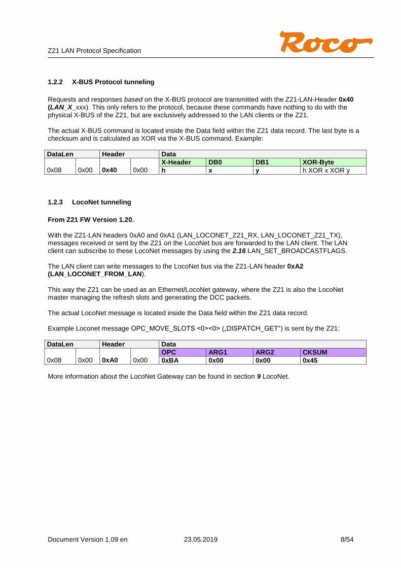
1.2.2 X-BUS Protocol tunneling
Requests and responses based on the X-BUS protocol are transmitted with the Z21-LAN-Header 0x40 (LAN_X_xxx). This only refers to the protocol, because these commands have nothing to do with the physical X-BUS of the Z21, but are exclusively addressed to the LAN clients or the Z21. The actual X-BUS command is located inside the Data field within the Z21 data record. The last byte is a checksum and is calculated as XOR via the X-BUS command. Example:
DataLen Header Data
0x08
0x00
0x40
0x00
X-Header DB0 DB1 XOR-Byte
h x y h XOR x XOR y
1.2.3 LocoNet tunneling
From Z21 FW Version 1.20. With the Z21-LAN headers 0xA0 and 0xA1 (LAN_LOCONET_Z21_RX, LAN_LOCONET_Z21_TX), messages received or sent by the Z21 on the LocoNet bus are forwarded to the LAN client. The LAN client can subscribe to these LocoNet messages by using the 2.16 LAN_SET_BROADCASTFLAGS. The LAN client can write messages to the LocoNet bus via the Z21-LAN header 0xA2 (LAN_LOCONET_FROM_LAN). This way the Z21 can be used as an Ethernet/LocoNet gateway, where the Z21 is also the LocoNet master managing the refresh slots and generating the DCC packets. The actual LocoNet message is located inside the Data field within the Z21 data record. Example Loconet message OPC_MOVE_SLOTS <0><0> („DISPATCH_GET“) is sent by the Z21:
DataLen Header Data
0x08
0x00
0xA0
0x00
OPC ARG1 ARG2 CKSUM
0xBA 0x00 0x00 0x45
More information about the LocoNet Gateway can be found in section 9 LocoNet.
Z21 LAN Protocol Specification
Document Version 1.09 en 23.05.2019 9/54
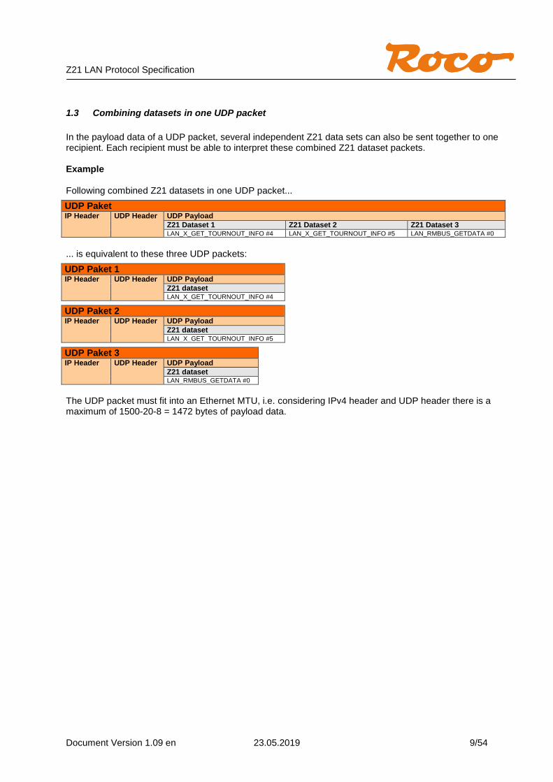
1.3 Combining datasets in one UDP packet
In the payload data of a UDP packet, several independent Z21 data sets can also be sent together to one recipient. Each recipient must be able to interpret these combined Z21 dataset packets. Example Following combined Z21 datasets in one UDP packet...
UDP Paket IP Header UDP Header UDP Payload
Z21 Dataset 1 Z21 Dataset 2 Z21 Dataset 3 LAN_X_GET_TOURNOUT_INFO #4 LAN_X_GET_TOURNOUT_INFO #5 LAN_RMBUS_GETDATA #0
... is equivalent to these three UDP packets:
UDP Paket 1 IP Header UDP Header UDP Payload
Z21 dataset LAN_X_GET_TOURNOUT_INFO #4
UDP Paket 2 IP Header UDP Header UDP Payload
Z21 dataset LAN_X_GET_TOURNOUT_INFO #5
UDP Paket 3 IP Header UDP Header UDP Payload
Z21 dataset LAN_RMBUS_GETDATA #0
The UDP packet must fit into an Ethernet MTU, i.e. considering IPv4 header and UDP header there is a maximum of 1500-20-8 = 1472 bytes of payload data.

Z21 LAN Protocol Specification
Document Version 1.09 en 23.05.2019 10/54
2 System, Status, Versions
2.1 LAN_GET_SERIAL_NUMBER
Reading the serial number of the Z21. Request to Z21:
DataLen Header Data
0x04 0x00 0x10 0x00 -
Reply from Z21:
DataLen Header Data
0x08 0x00 0x10 0x00 32 Bits Serial number (little endian)
2.2 LAN_LOGOFF
Logging off the client from the Z21. Request to Z21:
DataLen Header Data
0x04 0x00 0x30 0x00 -
Reply from Z21: none Use the same port number when logging out as when logging in. Note: the login is implicitly done with the first command of the client (e.g. LAN_SYSTEM_STATE_GETDATA, ...).
2.3 LAN_X_GET_VERSION
The X-Bus version of the Z21 can be read out with the following command. Request to Z21:
DataLen Header Data
0x07
0x00
0x40
0x00
X-Header DB0 XOR-Byte
0x21 0x21 0x00
Reply from Z21:
DataLen Header Data
0x09
0x00
0x40
0x00
X-Header DB0 DB1 DB2 XOR-Byte
0x63 0x21 0x30 0x12 0x60
DB1 … X-Bus Version 3.0 DB2 … command station ID, 0x12 = Z21
Z21 LAN Protocol Specification
Document Version 1.09 en 23.05.2019 11/54
2.4 LAN_X_GET_STATUS
This command can be used to request the Z21 status. Request to Z21:
DataLen Header Data
0x07
0x00
0x40
0x00
X-Header DB0 XOR-Byte
0x21 0x24 0x05
Reply from Z21: see 2.12 LAN_X_STATUS_CHANGED This command station status is identical to the CentralState, which is delivered in the system status, see 2.18 LAN_SYSTEMSTATE_DATACHANGED.
2.5 LAN_X_SET_TRACK_POWER_OFF
This command switches off the track voltage. Request to Z21:
DataLen Header Data
0x07
0x00
0x40
0x00
X-Header DB0 XOR-Byte
0x21 0x80 0xa1
Reply from Z21: see 2.7 LAN_X_BC_TRACK_POWER_OFF
2.6 LAN_X_SET_TRACK_POWER_ON
This command switches on the track voltage, or terminates either the emergency stop or the programming mode. Request to Z21:
DataLen Header Data
0x07
0x00
0x40
0x00
X-Header DB0 XOR-Byte
0x21 0x81 0xa0
Reply from Z21: see 2.8 LAN_X_BC_TRACK_POWER_ON

Z21 LAN Protocol Specification
Document Version 1.09 en 23.05.2019 12/54
2.7 LAN_X_BC_TRACK_POWER_OFF
The following packet is sent from the Z21 to the registered clients when
a client has sent command 2.5 LAN_X_SET_TRACK_POWER_OFF. or the track voltage has been switched off by some input device (multiMaus). and the relevant client has activated the corresponding broadcast,
see 2.16 LAN_SET_BROADCASTFLAGS, Flag 0x00000001 Z21 to Client:
DataLen Header Data
0x07
0x00
0x40
0x00
X-Header DB0 XOR-Byte
0x61 0x00 0x61
2.8 LAN_X_BC_TRACK_POWER_ON
The following packet is sent from the Z21 to the registered clients when
a client has sent command 2.6 LAN_X_SET_TRACK_POWER_ON. or the track voltage has been switched on by some input device (multiMaus). and the relevant client has activated the corresponding broadcast,
see 2.16 LAN_SET_BROADCASTFLAGS, Flag 0x00000001 Z21 to Client:
DataLen Header Data
0x07
0x00
0x40
0x00
X-Header DB0 XOR-Byte
0x61 0x01 0x60
2.9 LAN_X_BC_PROGRAMMING_MODE
The following packet is sent from the Z21 to the registered clients if the Z21 has been put into CV programming mode by 6.1 LAN_X_CV_READ or 6.2 LAN_X_CV_WRITE and the respective client has activated the corresponding broadcast, see 2.16 LAN_SET_BROADCASTFLAGS, Flag 0x00000001 Z21 to Client:
DataLen Header Data
0x07
0x00
0x40
0x00
X-Header DB0 XOR-Byte
0x61 0x02 0x63
2.10 LAN_X_BC_TRACK_SHORT_CIRCUIT
The following packet is sent from the Z21 to the registered clients if a short circuit has occurred and the relevant client has activated the corresponding broadcast, see 2.16 LAN_SET_BROADCASTFLAGS, Flag 0x00000001 Z21 to Client:
DataLen Header Data
0x07
0x00
0x40
0x00
X-Header DB0 XOR-Byte
0x61 0x08 0x69
Z21 LAN Protocol Specification
Document Version 1.09 en 23.05.2019 13/54
2.11 LAN_X_UNKNOWN_COMMAND
The following packet is sent from the Z21 to the client in response to an invalid request. Z21 to Client:
DataLen Header Data
0x07
0x00
0x40
0x00
X-Header DB0 XOR-Byte
0x61 0x82 E3
2.12 LAN_X_STATUS_CHANGED
The following packet is sent from the Z21 to the client if the client explicitly sets the status to 2.4 LAN_X_GET_STATUS. Z21 to Client:
DataLen Header Data
0x08
0x00
0x40
0x00
X-Header DB0 DB1 XOR-Byte
0x62 0x22 Status XOR-Byte
DB1 … command station status Bitmask for command station status: #define csEmergencyStop 0x01 // The emergency stop is switched on
#define csTrackVoltageOff 0x02 // The track voltage is switched off.
#define csShortCircuit 0x04 // Short-circuit
#define csProgrammingModeActive 0x20 // The programming mode is active
This command station status is identical to the SystemState.CentralState, see 2.18 LAN_SYSTEMSTATE_DATACHANGED.
Z21 LAN Protocol Specification
Document Version 1.09 en 23.05.2019 14/54
2.13 LAN_X_SET_STOP
With this command the emergency stop is activated, i.e. the locomotives are stopped but the track voltage remains switched on. Request to Z21:
DataLen Header Data
0x06
0x00
0x40
0x00
X-Header XOR-Byte
0x80 0x80
Reply from Z21: see 2.14 LAN_X_BC_STOPPED
2.14 LAN_X_BC_STOPPED
The following packet is sent from the Z21 to the registered clients when
a client has sent command 2.13 LAN_X_SET_STOP. or the emergency stop was triggered by some input device (multiMaus). and the relevant client has activated the corresponding broadcast, see
2.16 LAN_SET_BROADCASTFLAGS, Flag 0x00000001 Z21 to Client:
DataLen Header Data
0x07
0x00
0x40
0x00
X-Header DB0 XOR-Byte
0x81 0x00 0x81
2.15 LAN_X_GET_FIRMWARE_VERSION
The firmware version of the Z21 can be read with this command. Request to Z21:
DataLen Header Data
0x07
0x00
0x40
0x00
X-Header DB0 XOR-Byte
0xF1 0x0A 0xFB
Reply from Z21:
DataLen Header Data
0x09
0x00
0x40
0x00
X-Header DB0 DB1 DB2 XOR-Byte
0xF3 0x0A V_MSB V_LSB XOR-Byte
DB1 … MSB of the Firmware version DB2 … LSB of the Firmware version The version is specified in BCD format. Example: 0x09 0x00 0x40 0x00 0xf3 0x0a 0x01 0x23 0xdb … means: „Firmware Version 1.23“
Z21 LAN Protocol Specification
Document Version 1.09 en 23.05.2019 15/54
2.16 LAN_SET_BROADCASTFLAGS
Set the broadcast flags in the Z21. These flags are set per client (i.e. per IP + port number) and must be set again the next time you log on. Request to Z21:
DataLen Header Data
0x08 0x00 0x50 0x00 32 Bits Broadcast-Flags (little endian)
Broadcast flags are an OR-combination of the following values: 0x00000001 Broadcasts and info messages concerning driving and switching are delivered to the
registered clients automatically. The following messages are concerned: 2.7 LAN_X_BC_TRACK_POWER_OFF 2.8 LAN_X_BC_TRACK_POWER_ON 2.9 LAN_X_BC_PROGRAMMING_MODE 2.10 LAN_X_BC_TRACK_SHORT_CIRCUIT 2.14 LAN_X_BC_STOPPED 4.4 LAN_X_LOCO_INFO (loco address must be subscribed too) 5.3 LAN_X_TURNOUT_INFO
0x00000002 Changes of the feedback devices on the R-Bus are sent automatically. Z21 Broadcast messages see 7.1 LAN_RMBUS_DATACHANGED 0x00000004 Changes of RailCom data of subscribed locomotives are sent automatically.
Z21 Broadcast messages see 8.1 LAN_RAILCOM_DATACHANGED 0x00000100 Changes of the Z21 system status are sent automatically. Z21 Broadcast messages see 2.18 LAN_SYSTEMSTATE_DATACHANGED From Z21 FW Version 1.20: 0x00010000 Extends flag 0x00000001; client now gets LAN_X_LOCO_INFO LAN_X_LOCO_INFO
without having to subscribe to the corresponding locomotive addresses, i.e. for all controlled locomotives! Due to the high network traffic, this flag may only be used by adequate PC railroad automation software and is NOT intended for mobile hand controllers under any circumstances.
From FW V1.20 bis V1.23: LAN_X_LOCO_INFO is sent for all locomotives. From FW V1.24: LAN_X_LOCO_INFO is sent for all modified locomotives. 0x01000000 Forwarding messages from LocoNet bus to LAN client without locos and switches. 0x02000000 Forwarding locomotive-specific LocoNet messages to LAN Client: OPC_LOCO_SPD, OPC_LOCO_DIRF, OPC_LOCO_SND, OPC_LOCO_F912, OPC_EXP_CMD 0x04000000 Forwarding switch-specific LocoNet messages to LAN client: OPC_SW_REQ, OPC_SW_REP, OPC_SW_ACK, OPC_SW_STATE See also chapter 9 LocoNet. From Z21 FW Version 1.22: 0x08000000 Sending status changes of LocoNet track occupancy detectors to the LAN client.
See 9.5 LAN_LOCONET_DETECTOR From Z21 FW Version 1.29: 0x00040000 Sending changes of RailCom data to the LAN Client.
Client gets LAN_RAILCOM_DATACHANGED without having to subscribe to the corresponding locomotive addresses, i.e. for all controlled locomotives! Due to the high network traffic, this flag may only be used by adequate PC railroad automation software and is NOT intended for mobile hand controllers under any circumstances. Z21 Broadcast messages see 8.1 LAN_RAILCOM_DATACHANGED

Z21 LAN Protocol Specification
Document Version 1.09 en 23.05.2019 16/54
From Z21 FW Version 1.30: 0x00080000 Sending status changes of CAN-Bus track occupancy detectors to the LAN client. See 10.1 LAN_CAN_DETECTOR Reply from Z21: none When preparing the settings for the broadcast flags, always consider the effects on the network load. This applies in particular to the broadcast flags 0x00010000, 0x00040000, 0x02000000 and 0x04000000! The IP packets may be deleted by the router in case of overload and UDP does not offer any detection mechanisms for this! For example, before using flag 0x00000100 (system status) it is worth considering whether 0x00000001 with the corresponding LAN_X_BC_xxx broadcast messages would be a more suitable alternative. Not every application needs to be regularly informed in detail about the latest voltage, current and temperature values of the Z21.
2.17 LAN_GET_BROADCASTFLAGS
Reading the broadcast flags in the Z21. Request to Z21:
DataLen Header Data
0x04 0x00 0x51 0x00 -
Reply from Z21:
DataLen Header Data
0x08 0x00 0x51 0x00 Broadcast-Flags 32 Bit (little endian)
Broadcast-Flags see above.
2.18 LAN_SYSTEMSTATE_DATACHANGED
Reports a change in the system status from the Z21 to the client. This message is asynchronously reported to the client by the Z21 when the client
activated the corresponding broadcast, see 2.16 LAN_SET_BROADCASTFLAGS, Flag 0x00000100.
explicitly requested the system status, see 2.19 LAN_SYSTEMSTATE_GETDATA. Z21 to Client:
DataLen Header Data
0x14 0x00 0x84 0x00 SystemState (16 Bytes)
SystemState is structured as follows (the 16-bit values are little endian):
Byte Offset Typ Name
0 INT16 MainCurrent mA Current on the main track
2 INT16 ProgCurrent mA Current on programming track
4 INT16 FilteredMainCurrent mA smoothed current on the main track
6 INT16 Temperature °C command station internal temperature
8 UINT16 SupplyVoltage mV supply voltage
10 UINT16 VCCVoltage mV internal voltage, identical to track voltage
12 UINT8 CentralState bitmask see below
13 UINT8 CentralStateEx bitmask see below
14 UINT8 reserved
15 UINT8 reserved
Z21 LAN Protocol Specification
Document Version 1.09 en 23.05.2019 17/54
Bitmask for CentralState: #define csEmergencyStop 0x01 // The emergency stop is switched on
#define csTrackVoltageOff 0x02 // The track voltage is switched off
#define csShortCircuit 0x04 // Short-circuit
#define csProgrammingModeActive 0x20 // The programming mode is active
Bitmask for CentralStateEx: #define cseHighTemperature 0x01 // temperature too high
#define csePowerLost 0x02 // Input voltage too low
#define cseShortCircuitExternal 0x04 // S.C. at the external booster output
#define cseShortCircuitInternal 0x08 // S.C. at the main track or programming track
2.19 LAN_SYSTEMSTATE_GETDATA
Request the current system status. Request to Z21:
DataLen Header Data
0x04 0x00 0x85 0x00 -
Reply from Z21: see above 2.18 LAN_SYSTEMSTATE_DATACHANGED
2.20 LAN_GET_HWINFO
From Z21 FW Version 1.20 and SmartRail FW Version V1.13. Read the hardware type and the firmware version of the Z21. Request to Z21:
DataLen Header Data
0x04 0x00 0x1A 0x00 -
Reply from Z21:
DataLen Header Data
0x0C 0x00 0x1A 0x00 HwType 32 Bit (little endian) FW Version 32 Bit (little endian)
HwType: #define D_HWT_Z21_OLD 0x00000200 // „black Z21” (hardware variant from 2012)
#define D_HWT_Z21_NEW 0x00000201 // „black Z21”(hardware variant from 2013)
#define D_HWT_SMARTRAIL 0x00000202 // SmartRail (from 2012)
#define D_HWT_z21_SMALL 0x00000203 // „white z21” starter set variant (from 2013)
#define D_HWT_z21_START 0x00000204 // „z21 start” starter set variant (from 2016)
The FW version is specified in BCD format. Example: 0x0C 0x00 0x1A 0x00 0x00 0x02 0x00 0x00 0x20 0x01 0x00 0x00
means: „Hardware Type 0x200, Firmware Version 1.20“ To read out the version of an older firmware, use the alternative command 2.15 LAN_X_GET_FIRMWARE_VERSION. Apply following rules for older firmware versions:
V1.10 ... Z21 (hardware variant from 2012)
V1.11 ... Z21 (hardware variant from 2012)
V1.12 ... SmartRail (from 2012)

Z21 LAN Protocol Specification
Document Version 1.09 en 23.05.2019 18/54
2.21 LAN_GET_CODE
Read the software feature scope of the Z21 (and z21 or z21start of course). This command is of particular interest for the hardware variant "z21 start", in order to be able to check whether driving and switching via LAN is blocked or permitted. Request to Z21:
DataLen Header Data
0x04 0x00 0x18 0x00 -
Reply from Z21:
DataLen Header Data
0x05 0x00 0x18 0x00 Code (8 Bit)
Code: #define Z21_NO_LOCK 0x00 // all features permitted
#define z21_START_LOCKED 0x01 // „z21 start”: driving and switching is blocked
#define z21_START_UNLOCKED 0x02 // „z21 start”: driving and switching is permitted

Z21 LAN Protocol Specification
Document Version 1.09 en 23.05.2019 19/54
3 Settings The following settings described here are stored in the Z21 persistently. These settings can be reset by the user to the factory settings by keeping the STOP button on the Z21 pressed until the LEDs flash violet.
3.1 LAN_GET_LOCOMODE
Read the output format for a given locomotive address. In the Z21, the output format (DCC, MM) is persistently stored for each locomotive address. A maximum of 256 different locomotive addresses can be stored. Each address >= 256 is DCC automatically. Request to Z21:
DataLen Header Data
0x06 0x00 0x60 0x00 16 bits Loco-Address (big endian)
Reply from Z21:
DataLen Header Data
0x07 0x00 0x60 0x00 16 bits Loco-Address (big endian) Mode 8 bit
Loco Address 2 Bytes, big endian, i.e. first comes high byte, followed by low byte. Mode 0 ... DCC Format 1 ... MM Format
3.2 LAN_SET_LOCOMODE
Set the output format for a given locomotive address. The format is stored in the Z21persistently. Request to Z21:
DataLen Header Data
0x07 0x00 0x61 0x00 Loco address 16 Bit (big endian) Modus 8 bit
Reply from Z21: none Meaning of the values: see above. Note: each locomotive address >= 256 is and remains "Format DCC" automatically. Note: the speed steps (14, 28, 128) are also stored in the command station persistently. This automatically happens with the loco driving command, see 4.2 LAN_X_SET_LOCO_DRIVE.

Z21 LAN Protocol Specification
Document Version 1.09 en 23.05.2019 20/54
3.3 LAN_GET_TURNOUTMODE
Read the settings for a given accessory decoder address ("Accessory Decoder" RP-9.2.1). In the Z21, the output format (DCC, MM) is persistently stored for each accessory decoder address. A maximum of 256 different accessory decoder addresses can be stored. Each address >= 256 automatically is DCC. Request to Z21:
DataLen Header Data
0x06 0x00 0x70 0x00 16 bits Accessory Decoder Address (big endian)
Reply from Z21:
DataLen Header Data
0x07 0x00 0x70 0x00 16 bits Accessory Decoder Address (big endian) Mode 8 bit
Accessory Decoder Address 2 Bytes, big endian, i.e. first comes high byte, followed by low byte. Mode 0 ... DCC Format 1 ... MM Format At the LAN interface and in the Z21, the accessory decoder addresses are addressed from 0, but in the visualization in the apps or on the multiMaus from 1. This is only a decision of the visualization. Example: multiMaus switch address #3, corresponds to address 2 on the LAN and in Z21.
3.4 LAN_SET_TURNOUTMODE
Set the output format for a given accessory decoder address. The format is stored in the Z21 persistently. Request to Z21:
DataLen Header Data
0x07 0x00 0x71 0x00 16 bits Accessory Decoder Address (big endian) Mode 8 bit
Reply from Z21: none Meaning of the values: see above. MM accessory decoders are supported by Z21 firmware version 1.20 and higher. MM accessory decoders are not supported by SmartRail. Note: Each accessory decoder >= 256 is and remains DCC automatically.
Z21 LAN Protocol Specification
Document Version 1.09 en 23.05.2019 21/54
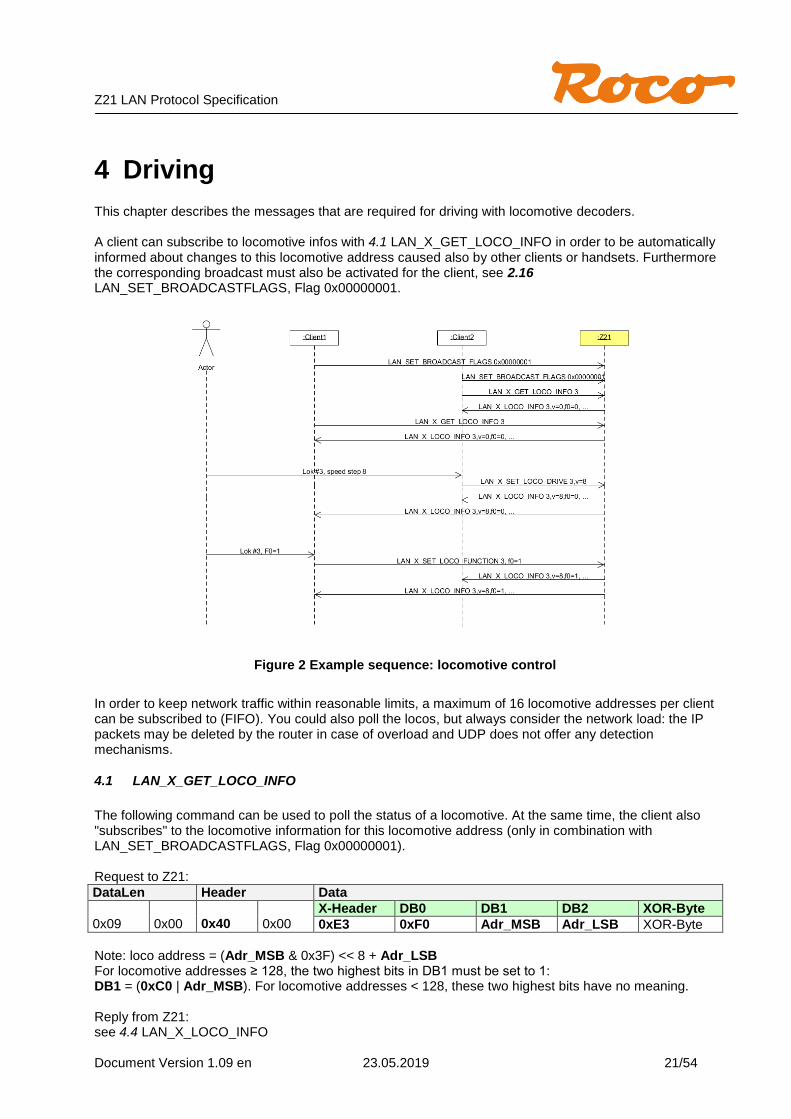
4 Driving This chapter describes the messages that are required for driving with locomotive decoders. A client can subscribe to locomotive infos with 4.1 LAN_X_GET_LOCO_INFO in order to be automatically informed about changes to this locomotive address caused also by other clients or handsets. Furthermore the corresponding broadcast must also be activated for the client, see 2.16 LAN_SET_BROADCASTFLAGS, Flag 0x00000001.
Figure 2 Example sequence: locomotive control
In order to keep network traffic within reasonable limits, a maximum of 16 locomotive addresses per client can be subscribed to (FIFO). You could also poll the locos, but always consider the network load: the IP packets may be deleted by the router in case of overload and UDP does not offer any detection mechanisms.
4.1 LAN_X_GET_LOCO_INFO
The following command can be used to poll the status of a locomotive. At the same time, the client also "subscribes" to the locomotive information for this locomotive address (only in combination with LAN_SET_BROADCASTFLAGS, Flag 0x00000001). Request to Z21:
DataLen Header Data
0x09
0x00
0x40
0x00
X-Header DB0 DB1 DB2 XOR-Byte
0xE3 0xF0 Adr_MSB Adr_LSB XOR-Byte
Note: loco address = (Adr_MSB & 0x3F) << 8 + Adr_LSB For locomotive addresses ≥ 128, the two highest bits in DB1 must be set to 1: DB1 = (0xC0 | Adr_MSB). For locomotive addresses < 128, these two highest bits have no meaning. Reply from Z21: see 4.4 LAN_X_LOCO_INFO

Z21 LAN Protocol Specification
Document Version 1.09 en 23.05.2019 22/54
4.2 LAN_X_SET_LOCO_DRIVE
Change the speed and direction of a locomotive. Request to Z21:
DataLen Header Data
0x0A
0x00
0x40
0x00
X-Header DB0 DB1 DB2 DB3 XOR-Byte
0xE4 0x1S Adr_MSB Adr_LSB RVVVVVVV XOR-Byte
Note: loco address = (Adr_MSB & 0x3F) << 8 + Adr_LSB For locomotive addresses ≥ 128, the two highest bits in DB1 must be set to 1: DB1 = (0xC0 | Adr_MSB). For locomotive addresses < 128, these two highest bits have no meaning. 0x1S Number of speed steps, depending on the rail format set
S=0: DCC 14 speed steps, or MMI with 14 speed steps and F0 S=2: DCC 28 speed steps, or MMII with 14 real speed steps and F0-F4 S=3: DCC 128 speed steps (aka “126 speed steps” when not counting the stops), or MMII with 28 real speed steps (using light-trit) and F0-F4
RVVVVVVV R ... Direction: 1=forward
V ... Speed: depending on the speed steps S. Coding see below. If the format MM is configured for the locomotive, the conversion of the given DCC speed stage into the real MM speed stage takes place automatically in the Z21.
The coding of the speed is similar to XpressNet™ (X-BUS), i.e. also similar to NMRA S 9.2 and S 9.2.1. “Stop” means “normal stop” or “step 0”. “E-Stop” means “immediate emergency stop”. Coding speed for “DCC 14”:
R000 VVVV Speed R000 VVVV Speed R000 VVVV Speed R000 VVVV Speed
R000 0000 Stop R000 0100 Step 3 R000 1000 Step 7 R000 1100 Step 11
R000 0001 E-Stop R000 0101 Step 4 R000 1001 Step 8 R000 1101 Step 12
R000 0010 Step 1 R000 0110 Step 5 R000 1010 Step 9 R000 1110 Step 13
R000 0011 Step 2 R000 0111 Step 6 R000 1011 Step 10 R000 1111 Step 14 max
Coding speed for “DCC 28” (like “DCC 14”, but with additional intermediate speed step in the fifth bit V5): R00V5 VVVV Speed R00V5 VVVV Speed R00V5 VVVV Speed R00V5 VVVV Speed
R000 0000 Stop R000 0100 Step 5 R000 1000 Step 13 R000 1100 Step 21
R001 0000 Stop1 R001 0100 Step 6 R001 1000 Step 14 R001 1100 Step 22
R000 0001 E-Stop R000 0101 Step 7 R000 1001 Step 15 R000 1101 Step 23
R001 0001 E-Stop1 R001 0101 Step 8 R001 1001 Step 16 R001 1101 Step 24
R000 0010 Step 1 R000 0110 Step 9 R000 1010 Step 17 R000 1110 Step 25
R001 0010 Step 2 R001 0110 Step 10 R001 1010 Step 18 R001 1110 Step 26
R000 0011 Step 3 R000 0111 Step 11 R000 1011 Step 19 R000 1111 Step 27
R001 0011 Step 4 R001 0111 Step 12 R001 1011 Step 20 R001 1111 Step 28 max
Coding speed for “DCC 128”: RVVV VVVV Speed
R000 0000 Stop
R000 0001 E-Stop
R000 0010 Step 1
R000 0011 Step 2
R000 0100 Step 3
R000 0101 Step 4
… …
R111 1110 Step 125 R111 1111 Step 126 max
1 Usage not recommended

Z21 LAN Protocol Specification
Document Version 1.09 en 23.05.2019 23/54
Reply from Z21: No standard reply, 4.4 LAN_X_LOCO_INFO to subscribed clients. Note: the number of speed steps (14/28/128) is automatically stored for the given loco address in the command station persistently.
4.3 LAN_X_SET_LOCO_FUNCTION
Change a function of a locomotive. Request to Z21:
DataLen Header Data
0x0A
0x00
0x40
0x00
X-Header DB0 DB1 DB2 DB3 XOR-Byte
0xE4 0xF8 Adr_MSB Adr_LSB TTNN NNNN XOR-Byte
Note: loco address = (Adr_MSB & 0x3F) << 8 + Adr_LSB For locomotive addresses ≥ 128, the two highest bits in DB1 must be set to 1: DB1 = (0xC0 | Adr_MSB). For locomotive addresses < 128, these two highest bits have no meaning. TT switch type: 00=off, 01=on, 10=toggle,11=not allowed NNNNNN Function index, 0x00=F0 (light), 0x01=F1 etc. Reply from Z21: No standard reply, 4.4 LAN_X_LOCO_INFO to subscribed clients.

Z21 LAN Protocol Specification
Document Version 1.09 en 23.05.2019 24/54
4.4 LAN_X_LOCO_INFO
This message is sent from the Z21 to the clients in response to the command 4.1 LAN_X_GET_LOCO_INFO. However, it is also unsolicitedly sent to an associated client if
the locomotive status has been changed by one of the (other) clients or handset controls and the associated client has activated the corresponding broadcast,
see 2.16 LAN_SET_BROADCASTFLAGS, Flag 0x00000001 and the associated client has subscribed to the locomotive address with 4.1
LAN_X_GET_LOCO_INFO. Z21 to Client:
DataLen Header Data
7 + n
0x00
0x40
0x00
X-Header DB0 ... ... ... ... ... ... ... DBn XOR-Byte
0xEF Locomotive Information XOR-Byte
The actual packet length n may vary depending on the data actually sent, with 7 n 14. The data for locomotive information is structured as follows:
Position Data Meaning
DB0 Adr_MSB The two highest bits in Adr_MSB must be ignored.
DB1 Adr_LSB Loco address = (Adr_MSB & 0x3F) << 8 + Adr_LSB
DB2 0000BKKK B=1 ... the locomotive is controlled by another X-BUS handset controller ("busy") KKK ... Speed steps information: 0=14, 2=28, 4=128
0: DCC 14 speed steps, or MMI with 14 speed steps and F0 2: DCC 28 speed steps, or MMII with 14 real speed stages and F0-F4 4: DCC 128 speed steps, or MMII with 28 real speed stages (light-trit) and F0-F4
DB3 RVVVVVVV R ... Directon: 1=forward V ... Speed. Coding also depends on the speed steps information KKK. See also above section 4.2 LAN_X_SET_LOCO_DRIVE. If the format MM is configured for the locomotive, then the conversion of the real MM speed step into the presented DCC speed step has already been done in the Z21.
DB4 0DSLFGHJ D ... double traction: 1=Loco included in a double traction S ... Smartsearch L ... F0 (Licht) F ... F4 G ... F3 H ... F2 J ... F1
DB5 F5-F12 Function F5 is bit0 (LSB)
DB6 F13-F20 Function F13 is bit0 (LSB)
DB7 F21-F28 Function F21 is bit0 (LSB)
DBn optional, for future extensions

Z21 LAN Protocol Specification
Document Version 1.09 en 23.05.2019 25/54
5 Switching This chapter deals with messages which are required for switching accessory decoders ("Accessory Decoder" according RP-9.2.1, e.g. decoder for turnouts, ...). The visualization of the turnout number on the user interface is differently solved in some DCC systems and can significantly differ from the real DCC accessory decoder address plus port actually used in the track signal. According to DCC, there are four ports with two outputs each per accessory decoder address. One turnout can be connected per port. Usually one of the following options is used to visualize the turnout number: 1. Numbering from 1 with DCC address at 1 starting with 4 ports each (ESU, Uhlenbrock, ...)
Switch #1: DCC-Addr=1 Port=0; Switch #5: DCC-Addr=2 Port=0; Switch #6: DCC-Addr=2 Port=1
2. Numbering from 1 with DCC address at 0 starting with 4 ports each (Roco) Switch #1: DCC-Addr=0 Port=0; Switch #5: DCC-Addr=1 Port=0; Switch #6: DCC-Addr=1 Port=1
3. Virtual switch number with freely configurable DCC address and port (Twin Center)
4. Displaying real DCC-address and port number (Zimo)
None of these visualization options can be described as “wrong” due to lack of specification in RP-9.2.1, where the visualization to the user is not mentioned at all. For the user, however, this can mean in consequence getting used to the fact that one and the same turnout at an ESU control panel is controlled under number 1, while it is switched on the Roco multiMaus and Z21 under number 5 ("shift by 4"). In order to be able to implement the visualization of your choice in your application, it helps to know how the Z21 converts the input parameters for the switching commands (FAdr_MSB, FAdr_LSB, A, P, see below) into the corresponding DCC accessory command: DCC basic accessory decoder packet format: {preamble} 0 10AAAAAA 0 1aaaCDDd 0 EEEEEEEE 1
UINT16 FAdr = (FAdr_MSB << 8) + FAdr_LSB; UINT16 Dcc_Addr = FAdr >> 2; aaaAAAAAA = (~Dcc_Addr & 0x1C0) | (Dcc_Addr & 0x003F); // DCC Address C = A; // Activate or deactivate output DD = FAdr & 0x03; // Port d = P; // Switch to the left or to the right
Example: FAdr=0 equals DCC-Addr=0 Port=0; FAdr=3 equals DCC-Addr=0 Port=3; FAdr=4 equals DCC-Addr=1 Port=0; etc. On the other hand, for MM Format note: FAdr starts with 0, i.e. FAdr=0: MM-Addr=1; FAdr=1: MM-Addr=2; ... A client can subscribe to accessory info in order to be automatically notified of changes to accessory decoders caused by other clients or handsets. For this purpose, the corresponding broadcast must be activated for the client, see 2.16 LAN_SET_BROADCASTFLAGS, Flag 0x00000001. The actual position of the turnout depends on the cabling and possibly also on the configuration in the client's application. The command station cannot know anything about this, and that is why the following description deliberately omits the terms "straight" and "branching". Instead we will speak about “output 1” and “output 2”.
Z21 LAN Protocol Specification
Document Version 1.09 en 23.05.2019 26/54
5.1 LAN_X_GET_TURNOUT_INFO
The following command can be used to poll the status of a turnout (or any accessory function). Request to Z21:
DataLen Header Data
0x08
0x00
0x40
0x00
X-Header DB0 DB1 XOR-Byte
0x43 FAdr_MSB FAdr_LSB XOR-Byte
Note: Function address = (FAdr_MSB << 8) + FAdr_LSB Reply from Z21: see 5.3 LAN_X_TURNOUT_INFO
5.2 LAN_X_SET_TURNOUT
A turnout (or any accessory function) can be switched with the following command. Request to Z21:
DataLen Header Data
0x09
0x00
0x40
0x00
X-Header DB0 DB1 DB2 XOR-Byte
0x53 FAdr_MSB FAdr_LSB 10Q0A00P XOR-Byte
Note: Function address = (FAdr_MSB << 8) + FAdr_LSB 1000A00P A=0 ... Deactivate turnout output A=1 ... Activate turnout output P=0 ... Select output 1 of the turnout P=1 ... Select output 2 of the turnout Q=0 … Execute command immediately Q=1 … From Z21 FW V1.24: Insert turnout command into the queue of Z21 and deliver it as soon as possible to the track. Reply from Z21: No standard answer, 5.3 LAN_X_TURNOUT_INFO to subscribed clients. From Z21 FW V1.24 the Q flag ("Queue") was introduced.
5.2.1 LAN_X_SET_TURNOUT with Q=0
With Q=0 the Z21 behaves compatible to the previous versions: the turnout switching command is immediately sent on the track by being mixed into the running loco driving commands. The Activate (A=1) is output until the LAN client sends the corresponding Deactivate. Only one switching command may be active at the same time. This behavior corresponds, for example, to pressing and releasing the multiMaus key. Please note that with Q=0 the correct sequence of the switching commands (i.e. Activate followed by Deactivate) must be observed strictly. Otherwise, undefined end positions may occur depending on the turnout decoder used. The LAN client is responsible for the correct serialization and the timing of the switching duration!

Z21 LAN Protocol Specification
Document Version 1.09 en 23.05.2019 27/54
Wrong: Activate turnout #5/A2 (4,0x89); Activate turnout #6/A2 (5,0x89); Activate turnout #3/A1 (2,0x88); Deactivate turnout #3/A1 (2,0x80); Deactivate turnout #5/A2 (4,0x81); Deactivate turnout #6/A2 (5,0x81); Correct: Activate turnout #5/A2 (4,0x89); wait 100ms; deactivate turnout #5/A2 (4,0x81); wait 50ms; Activate turnout #6/A2 (5,0x89); wait 100ms; deactivate turnout #6/A2 (5,0x81); wait 50ms; Activate turnout #3/A1 (2,0x88); wait 100ms; deactivate turnout #3/A1 (2,0x80); wait 50ms; Example: Activate turnout #7 / A2 (6,0x89); wait 150ms; deactivate turnout #7 / A2 (6,0x81)
Figure 3 DCC Sniff on track with Q=0

Z21 LAN Protocol Specification
Document Version 1.09 en 23.05.2019 28/54
5.2.2 LAN_X_SET_TURNOUT with Q=1
If Q=1, the following behavior occurs: in the Z21 the switching command is first put into an internal queue (FIFO). When generating the track signal, this queue is constantly checked whether a switching command is available for output. This switching command is then taken out of the queue and is written four times onto the track. This liberates the LAN client from the obligation of strict serialization, i.e. the switching commands may be sent mixed to the Z21 with Q=1 (very useful routes!). The LAN client only needs to take care of the Deactivate timing. Depending on the DCC decoder, the Deactivate may even be omitted. With MM you should not do without Deactivate, because e.g. the k83 and some older turnout decoders do not have an automatic shut-off. Example: Activate turnout #25 / A2 (24, 0xA9); Activate turnout #5 / A2 (4, 0xA9); Wait 150ms; Deactivate turnout #25 / A2 (24, 0xA1)
Figure 4 DCC Sniff on track with Q=1
Never mix switching commands with Q=0 and switching commands with Q=1 in your application.
Z21 LAN Protocol Specification
Document Version 1.09 en 23.05.2019 29/54
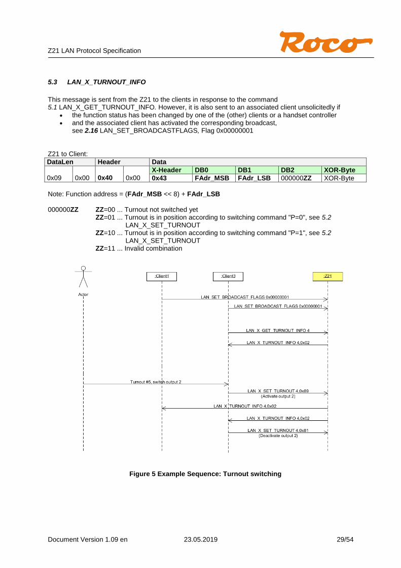
5.3 LAN_X_TURNOUT_INFO
This message is sent from the Z21 to the clients in response to the command 5.1 LAN_X_GET_TURNOUT_INFO. However, it is also sent to an associated client unsolicitedly if
the function status has been changed by one of the (other) clients or a handset controller and the associated client has activated the corresponding broadcast,
see 2.16 LAN_SET_BROADCASTFLAGS, Flag 0x00000001 Z21 to Client:
DataLen Header Data
0x09
0x00
0x40
0x00
X-Header DB0 DB1 DB2 XOR-Byte
0x43 FAdr_MSB FAdr_LSB 000000ZZ XOR-Byte
Note: Function address = (FAdr_MSB << 8) + FAdr_LSB 000000ZZ ZZ=00 ... Turnout not switched yet
ZZ=01 ... Turnout is in position according to switching command "P=0", see 5.2 LAN_X_SET_TURNOUT
ZZ=10 ... Turnout is in position according to switching command "P=1", see 5.2 LAN_X_SET_TURNOUT
ZZ=11 ... Invalid combination
Figure 5 Example Sequence: Turnout switching

Z21 LAN Protocol Specification
Document Version 1.09 en 23.05.2019 30/54
6 Reading and writing Decoder CVs This chapter deals with messages required for reading and writing decoder CVs (Configuration Variable, RP-9.2.2, RP-9.2.3). Whether the decoder is accessed bit-wise or byte-wise depends on the settings in the Z21.
6.1 LAN_X_CV_READ
Read a CV in direct mode. Request to Z21:
DataLen Header Data
0x09
0x00
0x40
0x00
X-Header DB0 DB1 DB2 XOR-Byte
0x23 0x11 CVAdr_MSB CVAdr_LSB XOR-Byte
Note: CV Address = (CVAdr_MSB << 8) + CVAdr_LSB, where 0=CV1, 1=CV2, 255=CV256, etc. Reply from Z21: 2.9 LAN_X_BC_PROGRAMMING_MODE to subscribed clients, as well as the result 6.3 LAN_X_CV_NACK_SC, 6.4 LAN_X_CV_NACK or 6.5 LAN_X_CV_RESULT.
6.2 LAN_X_CV_WRITE
Write a CV in direct mode. Request to Z21:
DataLen Header Data
0x0A
0x00
0x40
0x00
X-Header DB0 DB1 DB2 DB3 XOR-Byte
0x24 0x12 CVAdr_MSB CVAdr_LSB Value XOR-Byte
Note: CV-Address = (CVAdr_MSB << 8) + CVAdr_LSB, where 0=CV1, 1=CV2, 255=CV256, etc. Reply from Z21: 2.9 LAN_X_BC_PROGRAMMING_MODE to subscribed clients, as well as the result 6.3 LAN_X_CV_NACK_SC, 6.4 LAN_X_CV_NACK or 6.5 LAN_X_CV_RESULT.
6.3 LAN_X_CV_NACK_SC
If the programming failed due to a short circuit on the track, this message is automatically sent to the client that initiated the programming by 6.1 LAN_X_CV_READ or 6.2 LAN_X_CV_WRITE. Z21 to Client:
DataLen Header Data
0x07
0x00
0x40
0x00
X-Header DB0 XOR-Byte
0x61 0x12 0x73
Z21 LAN Protocol Specification
Document Version 1.09 en 23.05.2019 31/54
6.4 LAN_X_CV_NACK
If the ACK is missing from the decoder, this message is automatically sent to the client that initiated the programming by 6.1 LAN_X_CV_READ or 6.2 LAN_X_CV_WRITE. When reading with byte-wise access, the time until LAN_X_CV_NACK can be very long. Z21 to Client:
DataLen Header Data
0x07
0x00
0x40
0x00
X-Header DB0 XOR-Byte
0x61 0x13 0x72
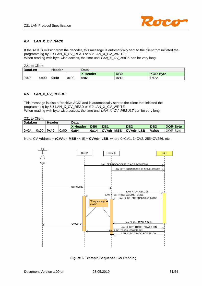
6.5 LAN_X_CV_RESULT
This message is also a "positive ACK" and is automatically sent to the client that initiated the programming by 6.1 LAN_X_CV_READ or 6.2 LAN_X_CV_WRITE. When reading with byte-wise access, the time until LAN_X_CV_RESULT can be very long. Z21 to Client:
DataLen Header Data
0x0A
0x00
0x40
0x00
X-Header DB0 DB1 DB2 DB3 XOR-Byte
0x64 0x14 CVAdr_MSB CVAdr_LSB Value XOR-Byte
Note: CV Address = (CVAdr_MSB << 8) + CVAdr_LSB, where 0=CV1, 1=CV2, 255=CV256, etc.
Figure 6 Example Sequence: CV Reading

Z21 LAN Protocol Specification
Document Version 1.09 en 23.05.2019 32/54
6.6 LAN_X_CV_POM_WRITE_BYTE
With the following command a CV of a locomotive decoder (“Multi Function Digital Decoders” according to NMRA S-9.2.1 Section C; Configuration Variable Access Instruction - Long Form) can be written on the main track (POM "Programming on the Main"). This is done in normal operating mode, i.e. the track voltage must be already switched on and the service mode is not activated. There is no feedback. Request to Z21:
DataLen Header Data
0x0C
0x00
0x40
0x00
X-Header DB0 DB1 DB2 DB3 DB4 DB5 XOR-Byte
0xE6 0x30 POM-Parameter XOR-Byte
The data for POM parameters is structured as follows:
Position Data Meaning
DB1 Adr_MSB
DB2 Adr_LSB Loco Address = (Adr_MSB & 0x3F) << 8 + Adr_LSB
DB3 111011MM Option ... 0xEC MM ... CVAdr_MSB
DB4 CVAdr_LSB CV Address = (MM << 8) + CVAdr_LSB (0=CV1., 1=CV2, 255=CV256, etc.)
DB5 Value New CV Value
Reply from Z21: none
6.7 LAN_X_CV_POM_WRITE_BIT
With the following command one bit of a CV of a locomotive decoder (“Multi Function Digital Decoders” according to NMRA S-9.2.1 Section C; Configuration Variable Access Instruction - Long Form) can be written on the main track (POM). This is done in normal operating mode, i.e. the track voltage must be already switched on and the service mode is not activated. There is no feedback. Request to Z21:
DataLen Header Data
0x0C
0x00
0x40
0x00
X-Header DB0 DB1 DB2 DB3 DB4 DB5 XOR-Byte
0xE6 0x30 POM-Parameter XOR-Byte
The data for POM parameters is structured as follows:
Position Data Meaning
DB1 Adr_MSB
DB2 Adr_LSB Loco Address = (Adr_MSB & 0x3F) << 8 + Adr_LSB
DB3 111010MM Option ... 0xE8 MM ... CVAdr_MSB
DB4 CVAdr_LSB CV Address = (MM << 8) + CVAdr_LSB (0=CV1., 1=CV2, 255=CV256, etc.)
DB5 0000VPPP PPP ... Bit-Position in CV V ... New CV Value
Reply from Z21: none
Z21 LAN Protocol Specification
Document Version 1.09 en 23.05.2019 33/54
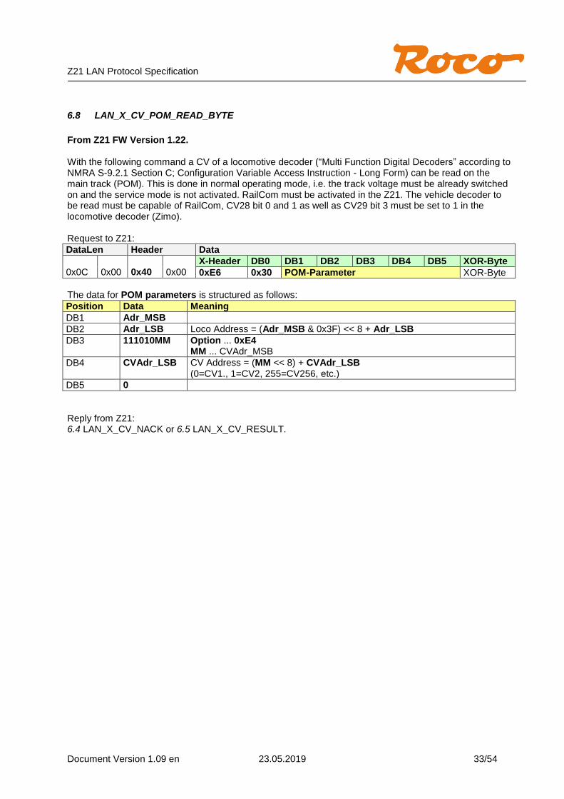
6.8 LAN_X_CV_POM_READ_BYTE
From Z21 FW Version 1.22. With the following command a CV of a locomotive decoder (“Multi Function Digital Decoders” according to NMRA S-9.2.1 Section C; Configuration Variable Access Instruction - Long Form) can be read on the main track (POM). This is done in normal operating mode, i.e. the track voltage must be already switched on and the service mode is not activated. RailCom must be activated in the Z21. The vehicle decoder to be read must be capable of RailCom, CV28 bit 0 and 1 as well as CV29 bit 3 must be set to 1 in the locomotive decoder (Zimo). Request to Z21:
DataLen Header Data
0x0C
0x00
0x40
0x00
X-Header DB0 DB1 DB2 DB3 DB4 DB5 XOR-Byte
0xE6 0x30 POM-Parameter XOR-Byte
The data for POM parameters is structured as follows:
Position Data Meaning
DB1 Adr_MSB
DB2 Adr_LSB Loco Address = (Adr_MSB & 0x3F) << 8 + Adr_LSB
DB3 111010MM Option ... 0xE4 MM ... CVAdr_MSB
DB4 CVAdr_LSB CV Address = (MM << 8) + CVAdr_LSB (0=CV1., 1=CV2, 255=CV256, etc.)
DB5 0
Reply from Z21: 6.4 LAN_X_CV_NACK or 6.5 LAN_X_CV_RESULT.

Z21 LAN Protocol Specification
Document Version 1.09 en 23.05.2019 34/54
6.9 LAN_X_CV_POM_ACCESSORY_WRITE_BYTE
From Z21 FW Version 1.22. With the following command a CV of an accessory decoder (according to NMRA S-9.2.1 Section D, “Basic Accessory Decoder Packet address for operations mode programming”) can be written on the main track (POM). This happens in normal operating mode, i.e. the track voltage must be already switched on and the service mode is not activated. There is no feedback. Request to Z21:
DataLen Header Data
0x0C
0x00
0x40
0x00
X-Header DB0 DB1 DB2 DB3 DB4 DB5 XOR-Byte
0xE6 0x31 POM-Parameter XOR-Byte
The data for POM parameters is structured as follows:
Position Data Meaning
DB1 aaaaa Decoder_Address MSB
DB2 AAAACDDD Note: aaaaaAAAACDDD = ((Decoder_Address & 0x1FF) << 4) | CDDD; In case CDDD=0000, then the CV refers to the whole decoder. In case C=1, then DDD is the number of the output to be programmed.
DB3 111011MM Option ... 0xEC MM ... CVAdr_MSB
DB4 CVAdr_LSB CV Address = (MM << 8) + CVAdr_LSB (0=CV1, 1=CV2, 255=CV256, etc.)
DB5 Value new CV value
Reply from Z21: none
6.10 LAN_X_CV_POM_ ACCESSORY_WRITE_BIT
From Z21 FW Version 1.22. With the following command a CV of an accessory decoder (according to NMRA S-9.2.1 Section D, “Basic Accessory Decoder Packet address for operations mode programming”) can be written on the main track (POM). This happens in normal operating mode, i.e. the track voltage must be already switched on and the service mode is not activated. There is no feedback. Request to Z21:
DataLen Header Data
0x0C
0x00
0x40
0x00
X-Header DB0 DB1 DB2 DB3 DB4 DB5 XOR-Byte
0xE6 0x31 POM-Parameter XOR-Byte
The data for POM parameters is structured as follows:
Position Data Meaning
DB1 aaaaa Decoder_Address MSB
DB2 AAAACDDD Note: aaaaaAAAACDDD = ((Decoder_Address & 0x1FF) << 4) | CDDD; In case CDDD=0000, then the CV refers to the whole decoder. In case C=1, then DDD is the number of the output to be programmed.
DB3 111010MM Option ... 0xE8 MM ... CVAdr_MSB
DB4 CVAdr_LSB CV Address = (MM << 8) + CVAdr_LSB (0=CV1, 1=CV2, 255=CV256, etc.)
DB5 0000VPPP PPP ... Bit position in CV V ... new CV value

Z21 LAN Protocol Specification
Document Version 1.09 en 23.05.2019 35/54
Reply from Z21: none
6.11 LAN_X_CV_POM_ ACCESSORY_READ_BYTE
From Z21 FW Version 1.22. With the following command a CV of an accessory decoder (according to NMRA S-9.2.1 Section D, “Basic Accessory Decoder Packet address for operations mode programming”) can be read on the main track (POM). This happens in normal operating mode, i.e. the track voltage must be already switched on, the service mode is not activated. RailCom must be activated in the Z21. The accessory decoder to be read must be capable of RailCom. Request to Z21:
DataLen Header Data
0x0C
0x00
0x40
0x00
X-Header DB0 DB1 DB2 DB3 DB4 DB5 XOR-Byte
0xE6 0x31 POM-Parameter XOR-Byte
The data for POM parameters is structured as follows:
Position Data Meaning
DB1 aaaaa Decoder_Address MSB
DB2 AAAACDDD Note: aaaaaAAAACDDD = ((Decoder_Address & 0x1FF) << 4) | CDDD; In case CDDD=0000, then the CV refers to the whole decoder. In case C=1, then DDD is the number of the output to be programmed.
DB3 111010MM Option ... 0xE4 MM ... CVAdr_MSB
DB4 CVAdr_LSB CV Address = (MM << 8) + CVAdr_LSB (0=CV1, 1=CV2, 255=CV256, etc.)
DB5 0 new CV value
Reply from Z21: 6.4 LAN_X_CV_NACK or 6.5 LAN_X_CV_RESULT.
Z21 LAN Protocol Specification
Document Version 1.09 en 23.05.2019 36/54
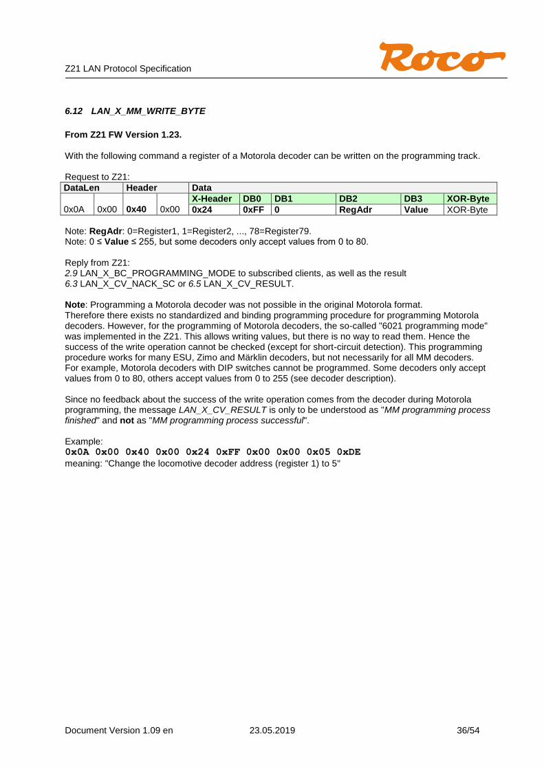
6.12 LAN_X_MM_WRITE_BYTE
From Z21 FW Version 1.23. With the following command a register of a Motorola decoder can be written on the programming track. Request to Z21:
DataLen Header Data
0x0A
0x00
0x40
0x00
X-Header DB0 DB1 DB2 DB3 XOR-Byte
0x24 0xFF 0 RegAdr Value XOR-Byte
Note: RegAdr: 0=Register1, 1=Register2, ..., 78=Register79. Note: 0 ≤ Value ≤ 255, but some decoders only accept values from 0 to 80. Reply from Z21: 2.9 LAN_X_BC_PROGRAMMING_MODE to subscribed clients, as well as the result 6.3 LAN_X_CV_NACK_SC or 6.5 LAN_X_CV_RESULT. Note: Programming a Motorola decoder was not possible in the original Motorola format. Therefore there exists no standardized and binding programming procedure for programming Motorola decoders. However, for the programming of Motorola decoders, the so-called "6021 programming mode" was implemented in the Z21. This allows writing values, but there is no way to read them. Hence the success of the write operation cannot be checked (except for short-circuit detection). This programming procedure works for many ESU, Zimo and Märklin decoders, but not necessarily for all MM decoders. For example, Motorola decoders with DIP switches cannot be programmed. Some decoders only accept values from 0 to 80, others accept values from 0 to 255 (see decoder description). Since no feedback about the success of the write operation comes from the decoder during Motorola programming, the message LAN_X_CV_RESULT is only to be understood as "MM programming process finished" and not as "MM programming process successful". Example: 0x0A 0x00 0x40 0x00 0x24 0xFF 0x00 0x00 0x05 0xDE
meaning: "Change the locomotive decoder address (register 1) to 5"

Z21 LAN Protocol Specification
Document Version 1.09 en 23.05.2019 37/54
6.13 LAN_X_DCC_READ_REGISTER
From Z21 FW Version 1.25. The following command can be used to read a register of a DCC decoder in register mode (S-9.2.3 Service Mode Instruction Packets for Physical Register Addressing) on the programming track. Request to Z21:
DataLen Header Data
0x08
0x00
0x40
0x00
X-Header DB0 DB1 XOR-Byte
0x22 0x11 REG XOR-Byte
Note: REG: 0x01=Register1, 0x02=Register2, …, 0x08=Register8. Note: 0 ≤ Value ≤ 255 Reply from Z21: 2.9 LAN_X_BC_PROGRAMMING_MODE to subscribed clients, as well as the result 6.3 LAN_X_CV_NACK_SC or 6.5 LAN_X_CV_RESULT. Note: Programming in register mode is only required for very old DCC decoders. Direct CV is preferred.
6.14 LAN_X_DCC_WRITE_REGISTER
From Z21 FW Version 1.25. With the following command a register of a DCC decoder in register mode (S-9.2.3 Service Mode Instruction Packets for Physical Register Addressing) can be written on the programming track. Request to Z21:
DataLen Header Data
0x09
0x00
0x40
0x00
X-Header DB0 DB2 DB3 XOR-Byte
0x23 0x12 REG Value XOR-Byte
Note: REG: 0x01=Register1, 0x02=Register2, …, 0x08=Register8. Note: 0 ≤ Value ≤ 255 Reply from Z21: 2.9 LAN_X_BC_PROGRAMMING_MODE to subscribed clients, as well as the result 6.3 LAN_X_CV_NACK_SC or 6.5 LAN_X_CV_RESULT. Note: Programming in register mode is only required for very old DCC decoders. Direct CV is preferred.
Z21 LAN Protocol Specification
Document Version 1.09 en 23.05.2019 38/54
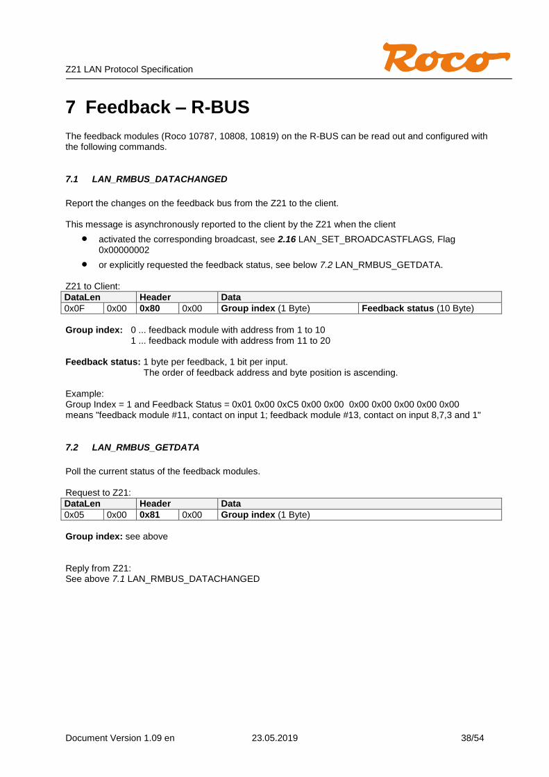
7 Feedback – R-BUS The feedback modules (Roco 10787, 10808, 10819) on the R-BUS can be read out and configured with the following commands.
7.1 LAN_RMBUS_DATACHANGED
Report the changes on the feedback bus from the Z21 to the client. This message is asynchronously reported to the client by the Z21 when the client
activated the corresponding broadcast, see 2.16 LAN_SET_BROADCASTFLAGS, Flag 0x00000002
or explicitly requested the feedback status, see below 7.2 LAN_RMBUS_GETDATA. Z21 to Client:
DataLen Header Data
0x0F 0x00 0x80 0x00 Group index (1 Byte) Feedback status (10 Byte)
Group index: 0 ... feedback module with address from 1 to 10
1 ... feedback module with address from 11 to 20 Feedback status: 1 byte per feedback, 1 bit per input.
The order of feedback address and byte position is ascending. Example: Group Index = 1 and Feedback Status = 0x01 0x00 0xC5 0x00 0x00 0x00 0x00 0x00 0x00 0x00 means "feedback module #11, contact on input 1; feedback module #13, contact on input 8,7,3 and 1"
7.2 LAN_RMBUS_GETDATA
Poll the current status of the feedback modules. Request to Z21:
DataLen Header Data
0x05 0x00 0x81 0x00 Group index (1 Byte)
Group index: see above Reply from Z21: See above 7.1 LAN_RMBUS_DATACHANGED
Z21 LAN Protocol Specification
Document Version 1.09 en 23.05.2019 39/54
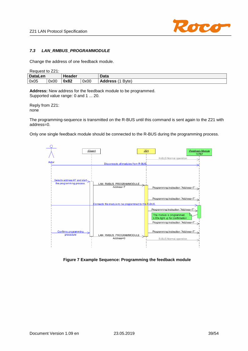
7.3 LAN_RMBUS_PROGRAMMODULE
Change the address of one feedback module. Request to Z21:
DataLen Header Data
0x05 0x00 0x82 0x00 Address (1 Byte)
Address: New address for the feedback module to be programmed. Supported value range: 0 and 1 ... 20. Reply from Z21: none The programming-sequence is transmitted on the R-BUS until this command is sent again to the Z21 with address=0. Only one single feedback module should be connected to the R-BUS during the programming process.
Figure 7 Example Sequence: Programming the feedback module

Z21 LAN Protocol Specification
Document Version 1.09 en 23.05.2019 40/54
8 RailCom The Z21 supports RailCom with:
Generating the RailCom cutout in the track signal.
Global RailCom receiver in the Z21.
Local RailCom receivers, e.g. in the occupancy detectors 10808 or boosters 10806 and 10807. The data from RailCom channel 2 of the 10806, 10807 and 10808 can be forwarded via CAN to the Z21 and evaluated there from FW V1.29 onwards.
Reading POM results. See also 6.8 LAN_X_CV_POM_READ_BYTE as of FW V1.22.
Locomotive address recognition for occupancy detectors (CAN, LocoNet, X-BUS). See 9.5 LAN_LOCONET_DETECTOR from V1.22 and 10.1 LAN_CAN_DETECTOR from V1.30.
Decoder speed (see below) from FW V1.29.
Decoder QoS (see below) from FW V1.29. In order to use these features, the decoder must be capable of RailCom, CV28 and CV29 must be correctly configured, and the option "RailCom" must activated in the Z21 settings. Note: It heavily depends on the decoder firmware whether and in which form a decoder supports speed, QoS and POM!
8.1 LAN_RAILCOM_DATACHANGED
This message is sent to the clients by the Z21 from FW version 1.29 on as a response to the command 8.2 LAN_RAILCOM_GETDATA. However, it is also sent to clients unsolicitedly, if
the corresponding RailCom data have actually changed and the associated client has activated the corresponding broadcast.
(see 2.16 LAN_SET_BROADCASTFLAGS, Flag 0x00000004) and the associated client has subscribed to the locomotive address with 4.1 LAN_X_GET_LOCO_INFO.
or the associated client has subscribed to broadcast 0x00040000 (i.e. RailCom data of all locomotives, for PC control SW only).
Z21 to Client:
DataLen Header Data
0x11 0x00 0x88 0x00 RailComData
The structure RailComData is structured as follows (the 16-bit and 32-bit values are little endian)
Byte Offset Type Name
0 UINT16 LocoAddress Address of the detected decoder
2 UINT32 ReceiveCounter Receive counter in Z21
6 UINT16 ErrorCounter Receive error counter in Z21
8 UINT8 reserved
9 UINT8 Options Flags bitmask: #define rcoSpeed1 0x01 // CH7 subindex 0
#define rcoSpeed2 0x02 // CH7 subindex 1
#define rcoQoS 0x04 // CH7 subindex 7
10 UINT8 Speed Speed 1 or 2 (if supported by decoder)
11 UINT8 QoS Quality of Service (if supported by decoder)
12 UINT8 reserved
The structure can be increased in the future versions; therefore it is absolutely necessary to consider DataLen in the evaluation.

Z21 LAN Protocol Specification
Document Version 1.09 en 23.05.2019 41/54
8.2 LAN_RAILCOM_GETDATA
Poll RailCom data from Z21, available from FW V1.29 and higher: Request to Z21:
DataLen Header Data
0x07 0x00 0x89 0x00 Type 8 bit LocoAddress 16 bit (little endian)
Type 0x01 = poll RailCom data for given locomotive address LocoAddress Loco address
0= poll RailCom data of next loco (circular buffer) Reply from Z21: See above 8.2 LAN_RAILCOM_DATACHANGED

Z21 LAN Protocol Specification
Document Version 1.09 en 23.05.2019 42/54
9 LocoNet From Z21 FW Version 1.20. As mentioned in the introduction, the Z21 can be used as an Ethernet/LocoNet gateway, where the Z21 is also the LocoNet master refreshing the slots and generating the DCC packets. The LAN client can subscribe to the corresponding LocoNet messages using 2.16 LAN_SET_BROADCASTFLAGS in order to receive also the messages from LocoNet. Messages received by the Z21 from the LocoNet bus are forwarded to the LAN client with the LAN header LAN_LOCONET_Z21_RX. Messages sent by the Z21 onto the LocoNet bus are also forwarded to the LAN client using the LAN header LAN_LOCONET_Z21_TX. With the Z21-LAN command LAN_LOCONET_FROM_LAN the LAN client itself can write messages onto the LocoNet bus. If there are other LAN clients with LocoNet subscriptions at the same time, they will also be notified with a message LAN_LOCONET_FROM_LAN. Only the actual sender will not be notified.
Figure 8 Example Sequence: Ethernet/LocoNet gateway
This example shows that even with trivial processes on the LocoNet bus, considerable network traffic can simultaneously occur on the Ethernet or WLAN. Please note that this Ethernet/LocoNet Gateway functionality has primarily been created for PC control SW as an additional tool for communicating with e.g. LocoNet feedback devices, etc.
When subscribing to the LocoNet messages, you should carefully consider whether the broadcast flags 0x02000000 (LocoNet locomotives) and 0x04000000 (LocoNet switches) are really necessary for your application. For conventional driving and switching, in particular, you should better use the LAN commands already described in chapters 4 Driving, 5 Switching and 6 Reading and writing Decoder CV.

Z21 LAN Protocol Specification
Document Version 1.09 en 23.05.2019 43/54
The actual LocoNet protocol is not described in more details in this specification. Please directly contact Digitrax or the manufacturer of the respective LocoNet hardware, especially if that manufacturer has extended the LocoNet protocol for e.g. configuration purposes etc.
9.1 LAN_LOCONET_Z21_RX
From Z21 FW Version 1.20. This message is asynchronously reported to the client by the Z21 when the client
activated the corresponding broadcast, see 2.16 LAN_SET_BROADCASTFLAGS, Flags 0x01000000, 0x02000000 or 0x04000000.
and a message has been received by the Z21 from the LocoNet bus. Z21 to Client:
DataLen Header Data
0x04+n
0x00
0xA0
0x00
LocoNet message incl. CKSUM
n Bytes
9.2 LAN_LOCONET_Z21_TX
From Z21 FW Version 1.20. This message is asynchronously reported to the client by the Z21 when the client
activated the corresponding broadcast, see 2.16 LAN_SET_BROADCASTFLAGS, Flags 0x01000000, 0x02000000 or 0x04000000.
and a message has been written to the LocoNet bus by the Z21. Z21 to Client:
DataLen Header Data
0x04+n
0x00
0xA1
0x00
LocoNet message incl. CKSUM
n Bytes
9.3 LAN_LOCONET_FROM_LAN
From Z21 FW Version 1.20. This message allows a LAN client to write a message to the LocoNet bus. This message is also asynchronously reported by the Z21 to a client when the client
activated the corresponding broadcast, see 2.16 LAN_SET_BROADCASTFLAGS, Flags 0x01000000, 0x02000000 or 0x04000000.
and another LAN client has written a message to the LocoNet bus via the Z21. LAN client to Z21, or Z21 to LAN client:
DataLen Header Data
0x04+n
0x00
0xA2
0x00
LocoNet message incl. CKSUM
n Bytes

Z21 LAN Protocol Specification
Document Version 1.09 en 23.05.2019 44/54
9.3.1 DCC Binary State Control Instruction
From FW Version V1.25 any DCC packets can be generated at the track output using LAN_LOCONET_FROM_LAN and the LocoNet command OPC_IMM_PACKET, among them the Binary State Control Instruction (also called "F29...F32767"). This also applies to the white z21, which has no physical LocoNet interface, but however has a virtual LocoNet stack inside. For the structure of the OPC_IMM_PACKET see LocoNet Spec (also in “personal edition” for learning purposes). For the structure of the Binary State Control Instruction see NMRA S-9.2.1 Section “Feature Expansion Instruction”.
9.4 LAN_LOCONET_DISPATCH_ADDR
From Z21 FW Version 1.20. Prepare a loco address for the LocoNet dispatch. This message allows a LAN client to prepare a specific locomotive address for the LocoNet dispatch. This corresponds to a "DISPATCH_PUT" and means that at the next "DISPATCH_GET" (triggered by handset controller) the slot belonging to this loco address is reported back by Z21. If necessary, the Z21 automatically occupies a free slot for this purpose. Request to Z21:
DataLen Header Data
0x06 0x00 0xA3 0x00 16 bits Loco address (little endian)
Reply from Z21: Z21 FW Version < 1.22: none Z21 FW Version ≥ 1.22: Z21 to Client:
DataLen Header Data
0x07 0x00 0xA3 0x00 16 bits Loco address (little endian) Result 8 bit
Result 0 The "DISPATCH_PUT" for the given address failed.
This can happen, for example, if the Z21 is operated as a LocoNet slave and the LocoNet master has rejected the dispatch request because this locomotive address is already assigned to another handset.
>0 The "DISPATCH_PUT" was executed successfully. The loco address can now be
transferred to a handset controller (e.g. FRED). The value of Result corresponds to the current LocoNet slot number for the given loco address.

Z21 LAN Protocol Specification
Document Version 1.09 en 23.05.2019 45/54
Figure 9 Example Sequence: LocoNet Dispatch per LAN-Client

Z21 LAN Protocol Specification
Document Version 1.09 en 23.05.2019 46/54
9.5 LAN_LOCONET_DETECTOR
From Z21 FW Version 1.22. If LAN client application wants to support a LocoNet track occupancy detector, there are two ways. The first would be to receive the LocoNet packets via 9.1 LAN_LOCONET_Z21_RX and process the corresponding LocoNet messages directly. However, this requires an exact knowledge of the LocoNet protocol and it would produce a lot of network traffic. Therefore the following alternative was created, with which you can poll the occupied status as well as be asynchronously informed about a change of the occupied status, without having to go into the depths of the LocoNet protocol. Information: please note the following essential difference between the Roco Feedback Module 10787 on the R-BUS (see 7 Feedback – R-BUS) and LocoNet Track Occupancy Detectors:
10787 is normally connected with mechanically operated switching contacts, which can be closed and reopened per axis of the train running over it.
LocoNet track occupancy detectors are usually based on exact current measurement at the monitored track section or on advanced technologies (transponder, infrared, RailCom, ..) in order to reliably determine the occupancy state of the track. During normal operation, ideally only one message is generated when the occupied state changes.
The following command can be used to poll the status of one or more track occupancy detectors. Request to Z21:
DataLen Header Data
0x07 0x00 0xA4 0x00 Type 8 bit 16 bits report address (little endian)
Type 0x80 Request via "Stationary Interrogate Request" (SIC) according to Digitrax
procedure. This procedure also can be used for the occupancy detectors from Blücher-Elektronik. The parameter “report address” is 0 (not relevant).
0x81 Request via so-called report address for Uhlenbrock occupancy detector.
This report address can be configured by the user e.g. UB63320 via LNCV 17 in the occupancy detector. The default value there is 1017. With type 0x81, this report address is only used for polling and should not be confused with the feedback address. Note: At the LocoNet bus this query is implemented via turnout switching commands, therefore the value according to LocoNet has to be decremented by 1. Example: 0x07 0x00 0xA4 0x00 0x81 0xF8 0x03
means: "request status of all occupancy detectors with report address 1017 (Report address = 1017 = 0x03F8 +1 = 1016 + 1)"
0x82 Status request for LISSY, from Z21 FW Version 1.23
On the other hand, for Uhlenbrock LISSY the report address corresponds to the feedback address however. The type of the subsequent feedback message(s) strongly depends on the configured operating mode of the LISSY receiver. In the LISSY manual you can find out more about the extensive setting options of the LISSY receiver.
Please note that in the case of a single request, several occupancy detectors may be addressed at the same time, and therefore multiple responses are to be expected. Depending on the manufacturer of the occupancy detector, the status of the same input can be also reported several times after one request.
Z21 LAN Protocol Specification
Document Version 1.09 en 23.05.2019 47/54
Reply from Z21: Z21 to Client:
DataLen Header Data
0x07 + n 0x00 0xA4 0x00 Type 8 bit Feedback address 16 bits (little endian)
Info[n]
This message is asynchronously reported to the client by the Z21 when the client
has activated the corresponding broadcast, see 2.16 LAN_SET_BROADCASTFLAGS, Flag 0x08000000
and the Z21 has received a corresponding message from a track occupancy detector due to a status change on its input, or due to an explicit status-request (polling) by a LAN client using the commands described above.
Feedback address Each input of an occupancy detector has its own feedback address, which can
be configured by the user (e.g. for Uhlenbrock and Blücher via LNCV), and which describes the monitored block with an unique address.
Info[n] Byte-Array; content and length n depending on Type, see below Type 0x01 For occupancy detector types like Uhlenbrock 63320 or Blücher GBM16XL
reporting only the status "occupied" and "free" (by using LocoNet OPC_INPUT_REP, X=1). n=1 Status of the input belonging to the feedback address can be found in Info[0]: Info[0]=0 ... sensor is LOW (“free”)
Info[0]=1 ... sensor is HIGH (“occupied”)
0x02 Transponder Enters Block 0x03 Transponder Exits Block
For occupancy detectors such as Blücher GBM16XN etc. reporting also the information about the vehicle (e.g. locomotive address) inside the block to the command station (by using LocoNet OPC_MULTI_SENSE transponding encoding from Digitrax). In addition to the feedback address, also a so-called transponder address is transmitted. The transponder address identifies the vehicle in the block. In the case of the GBM16XN, this is the locomotive address which was determined by the occupancy detector by using RailCom. n=2
The transponder address is located in Info[0] und Info[1], 16 Bit little endian: Info[0] ... transponder address low byte Info[1] ... transponder address high byte Remark: due to lack of specification inside the LocoNet spec, the value ranges in OPC_MULTI_SENSE is not quite clear, which leaves the manufacturers of the occupancy detectors sometimes in the dark. Therefore in the case of GBM16XN the following must be observed according to our experience:
o You have to add +1 to the feedback address to get the feedback address configured in GBM16XN.
o Depending on the configuration of the GBM16XN, the direction of the vehicle on the track can also be coded in the bit under the mask 0x1000. Such a configuration is not recommended because this bit collides with the address space of long locomotive addresses!

Z21 LAN Protocol Specification
Document Version 1.09 en 23.05.2019 48/54
0x10 LISSY Loco address from Z21 FW 1.23.
This message is sent to the Z21 LAN Client when an Uhlenbrock LISSY receiver reports a vehicle equipped with a LISSY transmitter and this LISSY receiver is configured to the "Transfer format (ÜF) Uhlenbrock" (LNCV 15=1). Furthermore, this message strongly depends on the configured operating mode (LNCV2, ...) of the LISSY receiver.
See also LISSY manual. n=3
The Loco address is located in Info[0] und Info[1], 16 Bit little endian: Info[0] ... loco address low byte Info[1] ... loco address high byte Locomotives have a value range from 1..9999 Wagons have a value range from 10000 to 16382 Info[2] ... Additional info according to following bits: 0 DIR1 DIR0 0 K3 K2 K1 K0 DIR1=0: DIR0 is to be ignored DIR1=1: DIR0=0 is forwards, DIR0=1 is backwards K3..K0: 4 bit “class information” stored in the LISSY sender. Example Configuration for Lissy Receiver 68610:
LNCV Value Comment
2 98 optional module reset: sets all LNCV to 0, except LNCV 0 and 1 (address)
2 0 Basic function: readout locomotive data and direction information by using double sensor
15 1 Send using “Transfer format (ÜF) Uhlenbrock” onto LocoNet
0x11 LISSY block status from Z21 FW 1.23. This message is sent to the Z21 LAN Client when an Uhlenbrock LISSY receiver sends a block occupancy status message using the "Transfer format (ÜF) Uhlenbrock". See also LISSY manual.
n=1
Status of the block belonging to the feedback address is in Info[0]: Info[0]=0 ... block is free
Info[0]=1 ... block is occupied
Example Configuration for Lissy Receiver 68610:
LNCV Value Comment
2 98 optional module reset: sets all LNCV to 0, except LNCV 0 and 1 (address)
2 22 Automation function with block status message: Time-controlled waiting station
3 2 Automation active in both driving directions
4 3 Wait time 3 seconds
10 2 Block option: Block status change to "free" after 2 seconds
15 1 Send using “transfer format (ÜF) Uhlenbrock” onto LocoNet

Z21 LAN Protocol Specification
Document Version 1.09 en 23.05.2019 49/54
0x12 LISSY Speed from Z21 FW 1.23.
This message is sent to the Z21 LAN Client when a Uhlenbrock LISSY receiver is configured for speed measurement. See also LISSY manual.
n=2
The speed is located in Info[0] and Info[1], 16 bit little endian: Info[0] ... speed low byte Info[1] ... speed high byte Example Configuration for Lissy Receiver 68610:
LNCV Value Comment
2 98 optional module reset: sets all LNCV to 0, except LNCV 0 and 1 (address)
2 0 Basic function: readout locomotive data and direction information by using double sensor
14 15660 Velocity Scaling factor = 1566 (H0-scale) * 10mm (sensor distance)
15 1 Send transfer format Uhlenbrock to LocoNet
Note: Type will be extended by further IDs in the future as required.
Z21 LAN Protocol Specification
Document Version 1.09 en 23.05.2019 50/54
10 CAN
10.1 LAN_CAN_DETECTOR
Ab Z21 FW Version 1.30. The Roco CAN occupancy detector 10808 is supported from FW version 1.30 on. The occupancy detector can be used by the LAN client in four different ways:
1. R-BUS emulation: the CAN detector is forwarded to the LAN client as R-BUS detector in the Z21 firmware. So the LAN client can use the CAN detector as described in Chapter 7 Feedback - R-BUS.
2. LocoNet emulation: the CAN detector is forwarded in the Z21 firmware as LocoNet detector to the LAN client. Thus the LAN client can use the CAN detector as described in chapter 9.5 LAN_LOCONET_DETECTOR (type 0x01 "occupied/free" and the locomotive address via type 0x02 and 0x03 "Transponder Enters Block, Transponder Exits Block").
3. LISSY emulation: The CAN detector is emulated in the Z21 firmware by LISSY/Marco messages. The LAN client can use the CAN detector as described in chapter 9.5 LAN_LOCONET_DETECTOR (type 0x10 "Locomotive address" and type 0x11 "block status").
4. Direct access by the command LAN_CAN_DETECTOR (see below). The type of emulation can be configured via the Z21 Maintenance Tool. The factory setting is: R-BUS emulation=on, LocoNet emulation=on, LISSY emulation=off. However, the fastest method, however, and the one that is most economic concerning memory and bandwidth, is direct access using the command LAN_CAN_DETECTOR 0xC4. This is particularly recommended when a large number of CAN occupancy detectors are used at the same time. With the following command, the status of the CAN occupancy detectors can be polled: Request to Z21:
DataLen Header Data
0x07 0x00 0xC4 0x00 Type 8 bit CAN-NetworkID 16 bit (little endian)
Type 0x00 Request the CAN occupancy detector with the given CAN network ID.
The CAN NetworkID 0xD000 means "all CAN detectors". Example:
0x07 0x00 0xC4 0x00 0x00 0x00 0xD0
means: "poll status of all CAN occupancy detectors"
Please note that with a single request several CAN occupancy detectors are addressed at the same time, and therefore multiple responses are to be expected. Depending on the configuration of the emulation, the status of one and the same input can also be reported several times.
Z21 LAN Protocol Specification
Document Version 1.09 en 23.05.2019 51/54
Reply from Z21: Z21 to Client:
DataLen Header Data
0x0E 0x00 0xC4 0x00 NId 16 bit
Addr 16 bit
Port 8 bit
Type 8 bit
Value1 16 bit
Value2 16 bit
This message is also reported to the client by the Z21 asynchronously when the client
Has activated the corresponding broadcast, see 2.16 LAN_SET_BROADCASTFLAGS, Flag 0x00080000
and the Z21 has received a corresponding message from the CAN detector, due to a status change at its input, OR due to an explicit polling by a LAN client using commands described above.
All 16 bit values are little endian coded. NId Unchangeable CAN network ID of the occupancy detector. Addr Configurable module address of the occupancy detector. Each CAN occupancy
detector has a module address which can be set by the user.
Port Input pin number of the CAN occupancy detector (0 to 7) Type 0x01 Occupancy status of input (free, busy, overload) 0x11 1
st and 2
nd recognized locomotive address at the entrance
0x12 3rd
and 4th recognized locomotive address at the entrance
… 0x1F 29
th and 30
th. recognized locomotive address at the entrance
The value of Value1 and Value2 depends on the type. If Type = 0x01 (occupied status): Value1 0x0000 Free, without voltage 0x0100 Free, with voltage 0x1000 Occupied, without voltage
0x1100 Occupied, with voltage 0x1201 Occupied, Overload 1 0x1202 Occupied, Overload 2 0x1203 Occupied, Overload 3
If Type = 0x11 to 0x1F (RailCom Loco address): Type 0x11 to 0x1F form a list of locomotive addresses. This vehicle list ends with the locomotive address=0. Value1 First detected locomotive address in section incl. direction information.
0 = no locomotive address detected (e.g. with decoder not capable of RailCom, or no locomotive), resp. end of locomotive address list
Value2 Second detected locomotive address in section incl. direction information. 0 = no locomotive address detected, resp. end of locomotive address list
The direction information is coded in the most significant two bits of Value1 resp. Value2: 0 x No direction detected 1 0 Vehicle has been placed forward on the track 1 1 Vehicle has been placed backwards on the track The lower 14 bits contain the locomotive address.

Z21 LAN Protocol Specification
Document Version 1.09 en 23.05.2019 52/54
Appendix A – Command overview
Client to Z21
Header Parameter Name
X-Header DB0 Parameter
0x10 - LAN_GET_SERIAL_NUMBER
0x18 - LAN_GET_CODE
0x1A - LAN_GET_HWINFO
0x30 - LAN_LOGOFF
0x40 0x21 0x21 - LAN_X_GET_VERSION
0x40 0x21 0x24 - LAN_X_GET_STATUS
0x40 0x21 0x80 - LAN_X_SET_TRACK_POWER_OFF
0x40 0x21 0x81 - LAN_X_SET_TRACK_POWER_ON
0x40 0x22 0x11 Register LAN_X_DCC_READ_REGISTER
0x40 0x23 0x11 CV-Address LAN_X_CV_READ
0x04 0x23 0x12 Register, Value LAN_X_DCC_WRITE_REGISTER
0x40 0x24 0x12 CV-Address, Value LAN_X_CV_WRITE
0x40 0x24 0xFF Register, Value LAN_X_MM_WRITE_BYTE
0x40 0x43 Turnout address LAN_X_GET_TURNOUT_INFO
0x40 0x53 Turnout address, Switching cmd LAN_X_SET_TURNOUT
0x40 0x80 - LAN_X_SET_STOP
0x40 0xE3 0xF0 Loco address LAN_X_GET_LOCO_INFO
0x40 0xE4 0x1s Loco address, Speed LAN_X_SET_LOCO_DRIVE
0x40 0xE4 0xF8 Loco address, Function LAN_X_SET_LOCO_FUNCTION
0x40 0xE6 0x30 POM-Param, Option 0xEC LAN_X_CV_POM_WRITE_BYTE
0x40 0xE6 0x30 POM-Param, Option 0xE8 LAN_X_CV_POM_WRITE_BIT
0x40 0xE6 0x30 POM-Param, Option 0xE4 LAN_X_CV_POM_READ_BYTE
0x40 0xE6 0x31 POM-Param, Option 0xEC LAN_X_CV_POM_ACCESSORY_WRITE_BYTE
0x40 0xE6 0x31 POM-Param, Option 0xE8 LAN_X_CV_POM_ ACCESSORY_WRITE_BIT
0x40 0xE6 0x31 POM-Param, Option 0xE4 LAN_X_CV_POM_ ACCESSORY_READ_BYTE
0x40 0xF1 0x0A - LAN_X_GET_FIRMWARE_VERSION
0x50 Broadcast-Flags LAN_SET_BROADCASTFLAGS
0x51 - LAN_GET_BROADCASTFLAGS
0x60 Loco address LAN_GET_LOCOMODE
0x61 Loco address, Mode LAN_SET_LOCOMODE
0x70 Accessory decoder address LAN_GET_TURNOUTMODE
0x71 Accessory decoder address, Mode LAN_SET_TURNOUTMODE
0x81 Group Index LAN_RMBUS_GETDATA
0x82 Address LAN_RMBUS_PROGRAMMODULE
0x85 - LAN_SYSTEMSTATE_GETDATA
0x89 Address LAN_RAILCOM_GETDATA
0xA2 LocoNet message LAN_LOCONET_FROM_LAN
0xA3 Loco address LAN_LOCONET_DISPATCH_ADDR
0xA4 Type, Report address LAN_LOCONET_DETECTOR
0xC4 Type, NId LAN_CAN_DETECTOR
Table 1 : Messages from Client to Z21

Z21 LAN Protocol Specification
Document Version 1.09 en 23.05.2019 53/54
Z21 to Client
Header Data Name X-Header DB0 Data
0x10 Serialnumber Reply to LAN_GET_SERIAL_NUMBER 0x18 Code Reply to LAN_GET_CODE 0x1A HWType, FW Version (BCD) Reply to LAN_GET_HWINFO 0x40 0x43 Turnout information LAN_X_TURNOUT_INFO
0x40 0x61 0x00 - LAN_X_BC_TRACK_POWER_OFF
0x40 0x61 0x01 - LAN_X_BC_TRACK_POWER_ON
0x40 0x61 0x02 - LAN_X_BC_PROGRAMMING_MODE
0x40 0x61 0x08 - LAN_X_BC_TRACK_SHORT_CIRCUIT
0x40 0x61 0x12 - LAN_X_CV_NACK_SC
0x40 0x61 0x13 - LAN_X_CV_NACK
0x40 0x61 0x82 - LAN_X_UNKNOWN_COMMAND
0x40 0x62 0x22 Status LAN_X_STATUS_CHANGED
0x40 0x63 0x21 XBus Version, ID Reply to LAN_X_GET_VERSION
0x40 0x64 0x14 CV-Result LAN_X_CV_RESULT
0x40 0x81 - LAN_X_BC_STOPPED
0x40 0xEF Loco information LAN_X_LOCO_INFO
0x40 0xF3 0x0A Version (BCD) Reply to LAN_X_GET_FIRMWARE_VERSION
0x51 Broadcast-Flags Reply to LAN_GET_BROADCASTFLAGS
0x60 Loco address, Mode Reply to LAN_GET_LOCOMODE
0x70 Accessory decoder address Reply to LAN_GET_TURNOUTMODE
0x80 Group index, Feedback status LAN_RMBUS_DATACHANGED
0x84 SystemState LAN_SYSTEMSTATE_DATACHANGED
0x88 RailComData LAN_RAILCOM_DATACHANGED
0xA0 LocoNet message LAN_LOCONET_Z21_RX
0xA1 LocoNet message LAN_LOCONET_Z21_TX
0xA2 LocoNet message LAN_LOCONET_FROM_LAN
0xA3 Loco address, Result LAN_LOCONET_DISPATCH_ADDR
0xA4 Type, Feedback address, Info LAN_LOCONET_DETECTOR
0xC4 Occupancy message LAN_CAN_DETECTOR
Table 2 : Messages from Z21 to Clients
Z21 LAN Protocol Specification
Document Version 1.09 en 23.05.2019 54/54
List of figures Figure 1 Example Sequence: Communication ............................................................................................. 7 Figure 2 Example sequence: locomotive control........................................................................................ 21 Figure 3 DCC Sniff on track with Q=0 ........................................................................................................ 27 Figure 4 DCC Sniff on track with Q=1 ........................................................................................................ 28 Figure 5 Example Sequence: Turnout switching ........................................................................................ 29 Figure 6 Example Sequence: CV Reading ................................................................................................. 31 Figure 7 Example Sequence: Programming the feedback module ............................................................ 39 Figure 8 Example Sequence: Ethernet/LocoNet gateway ......................................................................... 42 Figure 9 Example Sequence: LocoNet Dispatch per LAN-Client ............................................................... 45
List of tables Table 1 : Messages from Client to Z21 ...................................................................................................... 52 Table 2 : Messages from Z21 to Clients ..................................................................................................... 53