yzf-r1p yzf-r1pc - racersports.racer.net/docs/yamaha_yzfr1_02_service_manual_0-1.pdfeas00003 notice...
TRANSCRIPT

YZF-R1PYZF-R1PC
SERVICE MANUAL
LIT-11616-15-47 5PW-28197-10


EAS00000
YZF-R1P/YZF-R1PCSERVICE MANUAL
©2001 by Yamaha Motor Corporation, U.S.A.First edition, December 2001
All rights reserved.Any reproduction or unauthorized use
without the written permission ofYamaha Motor Corporation, U.S.A.
is expressly prohibited.Printed in U.S.A.
P/N LIT-11616-15-47
EAS00003
NOTICEThis manual was produced by the Yamaha Motor Company, Ltd. primarily for use by Yamaha deal-ers and their qualified mechanics. It is not possible to include all the knowledge of a mechanic inone manual. Therefore, anyone who uses this book to perform maintenance and repairs on Yamahavehicles should have a basic understanding of mechanics and the techniques to repair these typesof vehicles. Repair and maintenance work attempted by anyone without this knowledge is likely torender the vehicle unsafe and unfit for use.
This model has been designed and manufactured to perform within certain specifications in regardto performance and emissions. Proper service with the correct tools is necessary to ensure that thevehicle will operate as designed. If there is any question about a service procedure, it is imperativethat you contact a Yamaha dealer for any service information changes that apply to this model. Thispolicy is intended to provide the customer with the most satisfaction from his vehicle and to conformto federal environmental quality objectives.
Yamaha Motor Company, Ltd. is continually striving to improve all of its models. Modifications andsignificant changes in specifications or procedures will be forwarded to all authorized Yamaha deal-ers and will appear in future editions of this manual where applicable.
NOTE:_
• This Service Manual contains information regarding periodic maintenance to the emission controlsystem. Please read this material carefully.
• Designs and specifications are subject to change without notice.
EAS00004
IMPORTANT MANUAL INFORMATIONParticularly important information is distinguished in this manual by the following.
The Safety Alert Symbol means ATTENTION! BECOME ALERT! YOURSAFETY IS INVOLVED!
Failure to follow WARNING instructions could result in severe injury or death tothe motorcycle operator, a bystander or a person checking or repairing themotorcycle.
A CAUTION indicates special precautions that must be taken to avoid damageto the motorcycle.
A NOTE provides key information to make procedures easier or clearer.
WARNING
CAUTION:
NOTE:

EAS00007
HOW TO USE THIS MANUALThis manual is intended as a handy, easy-to-read reference book for the mechanic. Comprehensiveexplanations of all installation, removal, disassembly, assembly, repair and check procedures arelaid out with the individual steps in sequential order.1 The manual is divided into chapters. An abbreviation and symbol in the upper right corner of
each page indicate the current chapter. Refer to “SYMBOLS”.
2 Each chapter is divided into sections. The current section title is shown at the top of each page,except in chapter 3 (“PERIODIC CHECKS AND ADJUSTMENTS”), where the sub-section title(s)appears.
3 Sub-section titles appear in smaller print than the section title.
4 To help identify parts and clarify procedure steps, there are exploded diagrams at the start ofeach removal and disassembly section.
5 Numbers are given in the order of the jobs in the exploded diagram. A circled number indicates adisassembly step.
6 Symbols indicate parts to be lubricated or replaced. Refer to “SYMBOLS”.
7 A job instruction chart accompanies the exploded diagram, providing the order of jobs, names ofparts, notes in jobs, etc.
8 Jobs requiring more information (such as special tools and technical data) are described sequen-tially.
12
4
5
7
8
3
6

EAS00008
SYMBOLSThe following symbols are not relevant toevery vehicle. Symbols 1 to 9 indicate the subject of eachchapter.
1 General information 2 Specifications 3 Periodic checks and adjustments 4 Chassis 5 Engine 6 Cooling system 7 Fuel injection system8 Electrical system 9 Troubleshooting
Symbols 0 to G indicate the following.
0 Serviceable with engine mounted A Filling fluid B Lubricant C Special tool D Tightening torque E Wear limit, clearance F Engine speed G Electrical data
Symbols H to M in the exploded diagramsindicate the types of lubricants and lubricationpoints.
H Engine oil I Gear oil J Molybdenum-disulfide oilK Wheel-bearing greaseL Lithium-soap-base greaseM Molybdenum-disulfide grease
Symbols N to O in the exploded diagramsindicate the following.
N Apply locking agent (LOCTITE®) O Replace the part
1 2
3 4
5 6
7 8
9 0
A B
C D
E F G
H I J
K L M
N O
GENINFO SPEC
CHKADJ CHAS
ENG COOL
FI – +ELEC
TRBLSHTG
T R..
E G M
B LS M
LTNew

EAS00012
TABLE OF CONTENTS
GENERAL INFORMATION GEN INFO 1
SPECIFICATIONSSPEC 2
PERIODIC CHECKS AND ADJUSTMENTS CHK
ADJ 3CHASSIS
CHAS 4ENGINE
ENG 5COOLING SYSTEM
COOL 6FUEL INJECTION SYSTEM
FI 7ELECTRICAL SYSTEM
ELEC 8TROUBLESHOOTING TRBL
SHTG 9
– +

CHAPTER 1GENERAL INFORMATION
MOTORCYCLE IDENTIFICATION .................................................................1-1VEHICLE IDENTIFICATION NUMBER ....................................................1-1MODEL LABEL .........................................................................................1-1
FEATURES .....................................................................................................1-2OUTLINE OF FI SYSTEM ........................................................................1-2FI SYSTEM ...............................................................................................1-3COMPONENTS ........................................................................................1-5FUEL INJECTION SYSTEM ...................................................................1-16THREE-WAY CATALYTIC CONVERTER SYSTEM ..............................1-19INSTRUMENT FUNCTION .....................................................................1-20
IMPORTANT INFORMATION .......................................................................1-23PREPARATION FOR REMOVAL AND DISASSEMBLY ........................1-23REPLACEMENT PARTS ........................................................................1-23GASKETS, OIL SEALS AND O-RINGS .................................................1-23LOCK WASHERS/PLATES AND COTTER PINS ..................................1-24BEARINGS AND OIL SEALS .................................................................1-24CIRCLIPS ...............................................................................................1-24
CHECKING THE CONNECTIONS ...............................................................1-25
SPECIAL TOOLS .........................................................................................1-26
CHAPTER 2SPECIFICATIONS
GENERAL SPECIFICATIONS ........................................................................2-1
ENGINE SPECIFICATIONS ..........................................................................2-2
CHASSIS SPECIFICATIONS .......................................................................2-11
ELECTRICAL SPECIFICATIONS ................................................................2-15
CONVERSION TABLE .................................................................................2-17

TIGHTENING TORQUES .............................................................................2-17GENERAL TIGHTENING TORQUE SPECIFICATIONS ........................2-17ENGINE TIGHTENING TORQUES ........................................................2-18CHASSIS TIGHTENING TORQUES ......................................................2-21
LUBRICATION POINTS AND LUBRICANT TYPES ....................................2-23ENGINE ..................................................................................................2-23CHASSIS ................................................................................................2-24
COOLING SYSTEM DIAGRAMS .................................................................2-25
ENGINE OIL LUBRICATION CHART ..........................................................2-29
LUBRICATION DIAGRAMS .........................................................................2-30
CABLE ROUTING ........................................................................................2-35
CHAPTER 3PERIODIC CHECKS AND ADJUSTMENTS
INTRODUCTION .............................................................................................3-1
PERIODIC MAINTENANCE CHART FOR THE EMISSION CONTROL SYSTEM ..................................................3-1
GENERAL MAINTENANCE AND LUBRICATION CHART ...........................3-1
SEATS ............................................................................................................3-3
FUEL TANK ....................................................................................................3-4REMOVING THE FUEL TANK .................................................................3-5REMOVING THE FUEL PUMP ................................................................3-5INSTALLING THE FUEL PUMP ...............................................................3-6INSTALLING THE FUEL HOSE ...............................................................3-6
COWLINGS .....................................................................................................3-7
AIR FILTER CASE ..........................................................................................3-8

ENGINE ...........................................................................................................3-9ADJUSTING THE VALVE CLEARANCE ..................................................3-9SYNCHRONIZING THE THROTTLE BODIES .......................................3-14ADJUSTING THE ENGINE IDLING SPEED ..........................................3-16ADJUSTING THE THROTTLE CABLE FREE PLAY ..............................3-17CHECKING THE SPARK PLUGS ..........................................................3-19MEASURING THE COMPRESSION PRESSURE .................................3-20CHECKING THE ENGINE OIL LEVEL ...................................................3-23CHANGING THE ENGINE OIL ...............................................................3-24ADJUSTING THE CLUTCH CABLE FREE PLAY ..................................3-26REPLACING THE AIR FILTER ELEMENT ............................................3-28CHECKING THE FUEL AND BREATHER HOSES ................................3-29CHECKING THE CRANKCASE BREATHER HOSE ..............................3-29CHECKING THE EXHAUST SYSTEM ...................................................3-30ADJUSTING THE EXUP CABLES .........................................................3-31CHECKING THE COOLANT LEVEL ......................................................3-32CHECKING THE COOLING SYSTEM ...................................................3-33CHANGING THE COOLANT ..................................................................3-34
CHASSIS ......................................................................................................3-37ADJUSTING THE FRONT BRAKE .........................................................3-37ADJUSTING THE REAR BRAKE ...........................................................3-38CHECKING THE BRAKE FLUID LEVEL ................................................3-39CHECKING THE FRONT AND REAR BRAKE PADS ............................3-40ADJUSTING THE REAR BRAKE LIGHT SWITCH ................................3-40CHECKING THE FRONT AND REAR BRAKE HOSES .........................3-41BLEEDING THE HYDRAULIC BRAKE SYSTEM ...................................3-41ADJUSTING THE SHIFT PEDAL ...........................................................3-43ADJUSTING THE DRIVE CHAIN SLACK ..............................................3-43LUBRICATING THE DRIVE CHAIN .......................................................3-45CHECKING AND ADJUSTING THE STEERING HEAD ........................3-45CHECKING THE FRONT FORK ............................................................3-48ADJUSTING THE FRONT FORK LEGS ................................................3-49ADJUSTING THE REAR SHOCK ABSORBER ASSEMBLY .................3-51CHECKING THE TIRES .........................................................................3-53CHECKING THE WHEELS ....................................................................3-56CHECKING AND LUBRICATING THE CABLES ....................................3-57LUBRICATING THE LEVERS AND PEDALS ........................................3-57LUBRICATING THE SIDESTAND ..........................................................3-57LUBRICATING THE REAR SUSPENSION ............................................3-57
ELECTRICAL SYSTEM ................................................................................3-58CHECKING AND CHARGING THE BATTERY ......................................3-58CHECKING THE FUSES ........................................................................3-63REPLACING THE HEADLIGHT BULBS ................................................3-65ADJUSTING THE HEADLIGHT BEAM ..................................................3-66

CHAPTER 4CHASSIS
FRONT WHEEL AND BRAKE DISCS ...........................................................4-1FRONT WHEEL ........................................................................................4-2REMOVING THE FRONT WHEEL ...........................................................4-3CHECKING THE FRONT WHEEL ...........................................................4-3CHECKING THE BRAKE DISCS .............................................................4-5INSTALLING THE FRONT WHEEL .........................................................4-6ADJUSTING THE FRONT WHEEL STATIC BALANCE ...........................4-7
REAR WHEEL AND BRAKE DISC ................................................................4-9REAR WHEEL ........................................................................................4-10REMOVING THE REAR WHEEL ...........................................................4-12CHECKING THE REAR WHEEL ............................................................4-13CHECKING THE REAR WHEEL DRIVE HUB .......................................4-13CHECKING AND REPLACING THE REAR WHEEL SPROCKET .........4-14INSTALLING THE REAR WHEEL ..........................................................4-14ADJUSTING THE REAR WHEEL STATIC BALANCE ...........................4-15
FRONT AND REAR BRAKES ......................................................................4-16FRONT BRAKE PADS ...........................................................................4-16REAR BRAKE PADS ..............................................................................4-17REPLACING THE FRONT BRAKE PADS .............................................4-18REPLACING THE REAR BRAKE PADS ................................................4-21FRONT BRAKE MASTER CYLINDER ...................................................4-23REAR BRAKE MASTER CYLINDER .....................................................4-26DISASSEMBLING THE FRONT BRAKE MASTER CYLINDER .............4-28DISASSEMBLING THE REAR BRAKE MASTER CYLINDER ...............4-28CHECKING THE FRONT AND REAR BRAKE MASTER CYLINDERS ..........................................4-29ASSEMBLING AND INSTALLING THE FRONT BRAKE MASTER CYLINDER ..........................................4-30ASSEMBLING THE REAR BRAKE MASTER CYLINDER .....................4-32FRONT BRAKE CALIPERS ...................................................................4-34REAR BRAKE CALIPER ........................................................................4-36DISASSEMBLING THE FRONT BRAKE CALIPERS .............................4-38DISASSEMBLING THE REAR BRAKE CALIPER ..................................4-39CHECKING THE FRONT AND REAR BRAKE CALIPERS ....................4-40ASSEMBLING AND INSTALLING THE FRONT BRAKE CALIPERS ....4-41ASSEMBLING AND INSTALLING THE REAR BRAKE CALIPER .........4-43
FRONT FORK ...............................................................................................4-45REMOVING THE FRONT FORK LEGS .................................................4-48DISASSEMBLING THE FRONT FORK LEGS .......................................4-48CHECKING THE FRONT FORK LEGS ..................................................4-50ASSEMBLING THE FRONT FORK LEGS .............................................4-51INSTALLING THE FRONT FORK LEGS ................................................4-55

HANDLEBARS .............................................................................................4-56REMOVING THE HANDLEBARS ...........................................................4-58CHECKING THE HANDLEBARS ...........................................................4-58INSTALLING THE HANDLEBARS .........................................................4-58
STEERING HEAD .........................................................................................4-61REMOVING THE LOWER BRACKET ....................................................4-63CHECKING THE STEERING HEAD ......................................................4-63INSTALLING THE STEERING HEAD ....................................................4-64
REAR SHOCK ABSORBER ASSEMBLY ....................................................4-65HANDLING THE REAR SHOCK ABSORBER AND GAS CYLINDER ............................................................................4-66DISPOSING OF A REAR SHOCK ABSORBER AND GAS CYLINDER ............................................................................4-66REMOVING THE REAR SHOCK ABSORBER ASSEMBLY ..................4-67CHECKING THE REAR SHOCK ABSORBER ASSEMBLY ...................4-68INSTALLING THE REAR SHOCK ABSORBER ASSEMBLY .................4-68
SWINGARM AND DRIVE CHAIN .................................................................4-69REMOVING THE SWINGARM ...............................................................4-71REMOVING THE DRIVE CHAIN ............................................................4-72CHECKING THE SWINGARM ...............................................................4-72CHECKING THE DRIVE CHAIN ............................................................4-73INSTALLING THE SWINGARM .............................................................4-75
CHAPTER 5OVERHAULING THE ENGINE
ENGINE ...........................................................................................................5-1DRIVE SPROCKET ..................................................................................5-1EXHAUST PIPE ........................................................................................5-2LEADS AND HOSES ................................................................................5-4ENGINE ....................................................................................................5-6INSTALLING THE ENGINE ......................................................................5-7
CAMSHAFT ....................................................................................................5-8CYLINDER HEAD COVERS ...................................................................5-8CAMSHAFTS ............................................................................................5-9REMOVING THE CAMSHAFTS .............................................................5-11CHECKING THE CAMSHAFTS .............................................................5-12CHECKING THE TIMING CHAIN, CAMSHAFT SPROCKETS, AND TIMING CHAIN GUIDES ...............................................................5-14CHECKING THE TIMING CHAIN TENSIONER .....................................5-15INSTALLING THE CAMSHAFTS ...........................................................5-15

CYLINDER HEAD ........................................................................................5-19REMOVING THE CYLINDER HEAD ......................................................5-20CHECKING THE CYLINDER HEAD ......................................................5-20INSTALLING THE CYLINDER HEAD ....................................................5-21
VALVES AND VALVE SPRINGS ................................................................5-22REMOVING THE VALVES .....................................................................5-24CHECKING THE VALVES AND VALVE GUIDES ..................................5-25CHECKING THE VALVE SEATS ...........................................................5-27CHECKING THE VALVE SPRINGS .......................................................5-28CHECKING THE VALVE LIFTERS ........................................................5-29INSTALLING THE VALVES ....................................................................5-29
GENERATOR ..............................................................................................5-32REMOVING THE GENERATOR ............................................................5-33INSTALLING THE GENERATOR ...........................................................5-33
PICKUP COIL ..............................................................................................5-36REMOVING THE PICKUP COIL ROTOR ..............................................5-38INSTALLING THE PICKUP COIL ROTOR .............................................5-38
CLUTCH ........................................................................................................5-40CLUTCH COVER ..................................................................................5-40PULL LEVER SHAFT .............................................................................5-41CLUTCH .................................................................................................5-42REMOVING THE CLUTCH ....................................................................5-44CHECKING THE FRICTION PLATES ....................................................5-44CHECKING THE CLUTCH PLATES ......................................................5-45CHECKING THE CLUTCH HOUSING ...................................................5-45CHECKING THE CLUTCH BOSS ..........................................................5-45CHECKING THE PRESSURE PLATE ...................................................5-46CHECKING THE PULL LEVER SHAFT AND PULL ROD ......................5-46CHECKING THE STARTER CLUTCH ...................................................5-46INSTALLING THE CLUTCH ...................................................................5-47
SHIFT SHAFT ...............................................................................................5-49SHIFT SHAFT AND STOPPER LEVER ................................................5-49CHECKING THE SHIFT SHAFT ............................................................5-50CHECKING THE STOPPER LEVER ......................................................5-50INSTALLING THE SHIFT SHAFT ..........................................................5-50

OIL PAN AND OIL PUMP ............................................................................5-51OIL PUMP ...............................................................................................5-53REMOVING THE OIL PAN .....................................................................5-54CHECKING THE OIL PUMP ..................................................................5-54CHECKING THE RELIEF VALVE ..........................................................5-55CHECKING THE OIL DELIVERY PIPES ...............................................5-55CHECKING THE OIL STRAINER ...........................................................5-55ASSEMBLING THE OIL PUMP ..............................................................5-56INSTALLING THE OIL PUMP ................................................................5-56INSTALLING THE OIL STRAINER .........................................................5-57INSTALLING THE OIL PAN ...................................................................5-57
CRANKCASE ...............................................................................................5-58DISASSEMBLING THE CRANKCASE ...................................................5-60CHECKING THE CRANKCASE .............................................................5-61CHECKING THE BEARINGS AND OIL SEALS .....................................5-61CHECKING THE SPROCKET AND CHAINS .........................................5-61ASSEMBLING THE CRANKCASE .........................................................5-62
CONNECTING RODS AND PISTONS .........................................................5-64REMOVING THE CONNECTING RODS AND PISTONS ......................5-65REMOVING THE CRANKSHAFT ASSEMBLY ......................................5-66CHECKING THE CYLINDER AND PISTONS ........................................5-66CHECKING THE PISTON RINGS ..........................................................5-68CHECKING THE PISTON PINS .............................................................5-69CHECKING THE BIG END BEARINGS .................................................5-69INSTALLING THE CONNECTING ROD AND PISTON ..........................5-72
CRANKSHAFT .............................................................................................5-76CHECKING THE CRANKSHAFT ...........................................................5-77CHECKING THE CRANKSHAFT JOURNAL BEARINGS ......................5-77INSTALLING THE CRANKSHAFT .........................................................5-80
TRANSMISSION ...........................................................................................5-81REMOVING THE TRANSMISSION ........................................................5-87CHECKING THE SHIFT FORKS ............................................................5-87CHECKING THE SHIFT DRUM ASSEMBLY .........................................5-88CHECKING THE TRANSMISSION ........................................................5-88INSTALLING THE TRANSMISSION ......................................................5-89

CHAPTER 6COOLING SYSTEM
RADIATOR .....................................................................................................6-1CHECKING THE RADIATOR ...................................................................6-3INSTALLING THE RADIATOR .................................................................6-4
OIL COOLER ..................................................................................................6-5CHECKING THE OIL COOLER ................................................................6-6INSTALLING THE OIL COOLER ..............................................................6-6
THERMOSTAT ...............................................................................................6-7CHECKING THE THERMOSTAT ...........................................................6-10ASSEMBLING THE THERMOSTAT ASSEMBLY ..................................6-11INSTALLING THE THERMOSTAT ASSEMBLY ....................................6-11
WATER PUMP ..............................................................................................6-12DISASSEMBLING THE WATER PUMP .................................................6-14CHECKING THE WATER PUMP ...........................................................6-14ASSEMBLING THE WATER PUMP .......................................................6-15
CHAPTER 7FUEL INJECTION SYSTEM
FUEL INJECTION SYSTEM ...........................................................................7-1WIRING DIAGRAM ...................................................................................7-2ECU’S SELF-DIAGNOSTIC FUNCTION ..................................................7-3SUBSTITUTE CHARACTERISTICS OPERATION CONTROL (FAIL-SAFE ACTION) ..............................................................................7-4FAIL-SAFE ACTIONS TABLE ..................................................................7-4TROUBLESHOORING CHART ................................................................7-5DIAGNOSTIC MODE ................................................................................7-6TROUBLESHOOTING DETAILS ............................................................7-12
THROTTLE BODIES ....................................................................................7-29CHECKING THE INJECTOR ..................................................................7-33CHECKING THE THROTTLE BODY .....................................................7-33CHECKING THE PRESSURE REGULATOR .........................................7-34CHECKING THE FUEL PUMP AND PRESSURE REGULATOR OPERATION .....................................7-34CHECKING AND ADJUSTING THE THROTTLE POSITION SENSOR .................................................7-35

AIR INDUCTION SYSTEM ...........................................................................7-37AIR INDUCTION .....................................................................................7-37AIR CUT-OFF VALVE ............................................................................7-37AIR INDUCTION SYSTEM DIAGRAMS .................................................7-38CHECKING THE AIR INDUCTION SYSTEM .........................................7-39
CHAPTER 8ELECTRICAL
ELECTRICAL COMPONENTS .......................................................................8-1
CHECKING SWITCH CONTINUITY ...............................................................8-3
CHECKING THE SWITCHES .........................................................................8-4
CHECKING THE BULBS AND BULB SOCKETS .........................................8-5TYPES OF BULBS ...................................................................................8-5CHECKING THE CONDITION OF THE BULBS .......................................8-6CHECKING THE CONDITION OF THE BULB SOCKETS .......................8-7CHECKING THE LEDs .............................................................................8-7
IGNITION SYSTEM .........................................................................................8-8CIRCUIT DIAGRAM .................................................................................8-8TROUBLESHOOTING ..............................................................................8-9
ELECTRIC STARTING SYSTEM .................................................................8-13CIRCUIT DIAGRAM ...............................................................................8-13STARTING CIRCUIT CUT-OFF SYSTEM OPERATION .......................8-14TROUBLESHOOTING ............................................................................8-15STARTER MOTOR .................................................................................8-18CHECKING THE STARTER MOTOR ....................................................8-20ASSEMBLING THE STARTER MOTOR ................................................8-21
CHARGING SYSTEM ...................................................................................8-22CIRCUIT DIAGRAM ...............................................................................8-22TROUBLESHOOTING ............................................................................8-23
LIGHTING SYSTEM .....................................................................................8-25CIRCUIT DIAGRAM ...............................................................................8-25TROUBLESHOOTING ............................................................................8-27CHECKING THE LIGHTING SYSTEM ...................................................8-29
SIGNALING SYSTEM ...................................................................................8-32CIRCUIT DIAGRAM ...............................................................................8-32TROUBLESHOOTING ............................................................................8-34CHECKING THE SIGNALING SYSTEM ................................................8-34

COOLING SYSTEM ......................................................................................8-41CIRCUIT DIAGRAM ...............................................................................8-41TROUBLESHOOTING ............................................................................8-42
FUEL PUMP SYSTEM ..................................................................................8-45CIRCUIT DIAGRAM ...............................................................................8-45FUEL PUMP SYSTEM ...........................................................................8-46TROUBLESHOOTING ............................................................................8-47CHECKING THE FUEL PUMP ...............................................................8-49
CHAPTER 9TROUBLESHOOTING
STARTING FAILURES ...................................................................................9-1ENGINE ....................................................................................................9-1FUEL SYSTEM .........................................................................................9-1ELECTRICAL SYSTEMS .........................................................................9-2
INCORRECT ENGINE IDLING SPEED ..........................................................9-2ENGINE ....................................................................................................9-2FUEL SYSTEM .........................................................................................9-2ELECTRICAL SYSTEMS .........................................................................9-2
POOR MEDIUM-AND-HIGH-SPEED PERFORMANCE ................................9-3ENGINE ....................................................................................................9-3FUEL SYSTEM .........................................................................................9-3
FAULTY GEAR SHIFTING .............................................................................9-3SHIFTING IS DIFFICULT .........................................................................9-3SHIFT PEDAL DOES NOT MOVE ...........................................................9-3JUMPS OUT OF GEAR ............................................................................9-3
FAULTY CLUTCH ..........................................................................................9-3CLUTCH SLIPS ........................................................................................9-3CLUTCH DRAGS .....................................................................................9-3
OVERHEATING ..............................................................................................9-4ENGINE ....................................................................................................9-4COOLING SYSTEM .................................................................................9-4FUEL SYSTEM .........................................................................................9-4CHASSIS ..................................................................................................9-4ELECTRICAL SYSTEMS .........................................................................9-4
OVERCOOLING .............................................................................................9-4COOLING SYSTEM .................................................................................9-4
POOR BRAKING PERFORMANCE ...............................................................9-4

FAULTY FRONT FORK LEGS .......................................................................9-5LEAKING OIL ...........................................................................................9-5MALFUNCTION ........................................................................................9-5
UNSTABLE HANDLING .................................................................................9-5
FAULTY LIGHTING OR SIGNALING SYSTEM .............................................9-6HEADLIGHT DOES NOT COME ON .......................................................9-6HEADLIGHT BULB BURNT OUT .............................................................9-6TAIL/BRAKE LIGHT DOES NOT COME ON ...........................................9-6TAIL/BRAKE LIGHT BULB BURNT OUT .................................................9-6TURN SIGNAL DOES NOT COME ON ....................................................9-6TURN SIGNAL BLINKS SLOWLY ............................................................9-6TURN SIGNAL REMAINS LIT ..................................................................9-6TURN SIGNAL BLINKS QUICKLY ...........................................................9-6HORN DOES NOT SOUND .....................................................................9-6

1 - 1
GENINFO
EAS00014
GENERAL INFORMATION MOTORCYCLE IDENTIFICATIONEAS00017
VEHICLE IDENTIFICATION NUMBERThe vehicle identification number 1 isstamped into the right side of the steering headpipe.
EAS00018
MODEL LABELThe model label 1 is affixed to the frame. Thisinformation will be needed to order spareparts.
MOTORCYCLE IDENTIFICATION
1

1 - 2
GENINFOFEATURES
FEATURESOUTLINE OF FI SYSTEMThe main function of a fuel supply system is to provide fuel to the combustion chamber at the opti-mum air-fuel ratio in accordance with the engine operating conditions and the atmospheric tempera-ture.In the conventional carburetor system, the air-fuel ratio of the mixture that is supplied to the com-bustion chamber is created by the volume of the intake air and the fuel that is metered by the jet thatis used in the respective chamber.Despite the same volume of intake air, the fuel volume requirement varies by the engine operatingconditions, such as acceleration, deceleration, or operating under a heavy load. Carburetors thatmeter the fuel through the use of jets have been provided with various auxiliary devices, so that anoptimum air-fuel ratio can be achieved to accommodate the constant changes in the operating con-ditions of the engine.As the requirements for the engine to deliver more performance and cleaner exhaust gasesincrease, it becomes necessary to control the air-fuel ratio in a more precise and finely tuned man-ner. To accommodate this need, this model has adopted an electronically controlled fuel injection(FI) system, in place of the conventional carburetor system. This system can achieve an optimumair-fuel ratio required by the engine at all times by using a microprocessor that regulates the fuelinjection volume according to the engine operating conditions detected by various sensors.The adoption of the FI system has resulted in a highly precise fuel supply, improved engineresponse, better fuel economy, and reduced exhaust emissions. Furthermore, the air induction sys-tem (AI system) has been placed under computer control together with the FI system in order torealize cleaner exhaust gases.
1 Ignition coil 2 Air filter case3 Intake temperature
sensor4 Fuel delivery hose5 Fuel tank6 Fuel pump7 Fuel return hose
8 Intake air pressure sensor
9 Throttle position sensor0 Fuel injectorA Catalytic converterB Crankshaft position
sensorC Coolant temperature
sensor
D Spark plugE Cylinder identification
sensorF Pressure regulatorG BatteryH ECUI Atmospheric pressure
sensor
J Fuel injection system relay
K Engine trouble warn-ing light
L Lean angle cut-off switch
M Air cut-off valve

1 - 3
GENINFOFEATURES
FI SYSTEMThe fuel pump delivers fuel to the injector via the fuel filter. The pressure regulator maintains thefuel pressure that is applied to the injector at only 284 kPa (2.84 kg/cm2, 40.4 psi) higher than theintake manifold pressure. Accordingly, when the energizing signal from the ECU energizes theinjector, the fuel passage opens, causing the fuel to be injected into the intake manifold only duringthe time the passage remains open. Therefore, the longer the length of time the injector is energized(injection duration), the greater the volume of fuel that is supplied. Conversely, the shorter thelength of time the injector is energized (injection duration), the lesser the volume of fuel that is sup-plied.
The injection duration and the injection timing are controlled by the ECU. Signals that are input fromthe throttle position sensor, crankshaft position sensor, intake air pressure sensor, atmosphericpressure sensor, intake temperature sensor and coolant temperature sensor enable the ECU todetermine the injection duration. The injection timing is determined through the signals from thecrankshaft position sensor and the cylinder identification sensor. As a result, the volume of fuel thatis required by the engine can be supplied at all times in accordance with the driving conditions.
1 Fuel pump2 Pressure regulator3 Fuel injector4 Throttle body5 Intake temperature
sensor
6 Throttle position sensor7 Intake air pressure
sensor8 ECU9 Atmospheric pressure
sensor
0 Coolant temperature sensor
A Cylinder identification sensor
B Crankshaft position sensor
È Fuel systemÉ Air systemÊ Control system
Illustration is for reference only.

1 - 4
GENINFOFEATURES
Fuel control blockThe fuel control block consists of the following main components:
An engine trouble warning light is provided on meter panel.
Component Function
Control block ECU Total FI system control
Throttle body Air volume control
Pressure regulator Fuel pressure detection
Sensor block Intake air pressure sensor Intake air pressure detection
Atmospheric pressure sensor Atmospheric pressure detection
Coolant temperature sensor Coolant temperature detection
Intake temperature sensor Intake temperature detection
Throttle position sensor Throttle angle detection
Cylinder identification sensor Reference position detection
Crankshaft position sensor Crankshaft position detection and engineRPM detection
Speed sensor Speed detection
Actuator block Injector Fuel injection
Fuel pump Fuel feed
Air Induction system, air cut valve Induction of secondary air

1 - 5
GENINFOFEATURES
COMPONENTSECU (Electronic Control Unit)The ECU is mounted underneath the seat. The main functions of the ECU are ignition control, fuelcontrol, self-diagnosis, and load control.• ECU’s internal construction and functions
The main components and functions of the ECU can be broadly divided into the following fouritems:A. Power supply circuit
The power supply circuit obtains power from the battery (12 V) to supply the power (5 V) that isrequired for operating the ECU.
B. Input interface circuitsThe input interface circuits convert the signals output by all the sensors into digital signals,which can be processed by the CPU, and input them into the CPU.
C. CPU (Central Processing Unit)The CPU determines the condition of the sensors in accordance with the level of the signal thatis output by the respective sensor. Then, the signals are temporarily stored on the RAM in theCPU. Based on those stored signals and the basic processing program on the ROM, the CPUcalculates the fuel injection duration, injection timing, and ignition timing, and then sends con-trol commands to the respective output interface circuits.
D. Output interface circuitsThe output interface circuits convert the control signals output by the CPU into actuating sig-nals for the respective actuators in order to actuate them. They also output commands to theindicator and relay output circuits as needed.
Battery
Power supply circuit
ECU
Output interface circuit
Input interface circuit
CPU
RAM/ROM
MEMORY
Waveform shaping circuit
Waveform shaping circuit
Digital input circuit
A/D converter input circuit
Injector driveoutput circuit
Ignition output circuit
Relay driveoutput circuit
Hall sensorsignal
(for cylinderidentification)
Pickup coil signal(for identifying the
crankshaft position)
Switches
Sensors
Injector
Ignition coil
Relay
Communication interface circuit
Serial comunicationcircuit
Meter unit

1 - 6
GENINFOFEATURES
• Ignition controlThe ignition control function of the ECU controls the ignition timing and the duration of ignitionenergizing. The ignition timing control uses the signals from the throttle position sensor (to detectthe angle of the throttle), and the crankshaft position sensor and speed sensor (to detect thespeed of the engine). This control establishes an ignition timing that suits the operating conditionof the engine through compensations made to the basic ignition timing control map. The ignitionenergizing duration control establishes the energizing duration to suit the operating conditions bycalculating the energizing duration in accordance with the signal received from the crankshaftposition sensor and the battery voltage.
• Fuel controlThe fuel control function of the ECU controls the injection timing and injection duration. The injec-tion timing control controls the injection timing during the starting of the engine and the injectiontiming during the normal operation of the engine, based on the signals received from the crank-shaft position sensor and the cylinder identification sensor. The injection duration control deter-mines the duration of injection based on the signals received from the atmospheric pressuresensors, temperature sensors, and the position sensors, to which compensations are made to suitvarious conditions such as the weather, atmospheric pressure, starting, acceleration, and deceler-ation.
• Load controlThe ECU effects load control in the following manner:1. Stopping the fuel pump and injectors when the motorcycle overturns
The ECU turns OFF the fuel injection system relay when the lean angle cut-off switch is oper-ated.
2. Operating the headlight illumination relayThe ECU controls the headlight relay 2 in accordance with the engine speed as required by thedaytime illumination specification.
3. Operating the radiator fan motor in accordance with the coolant temperatureThe ECU controls the radiator fan motor relay ON/OFF in accordance with the coolant temper-ature.
4. Operating the AI system solenoid valveThe ECU controls the energizing of the solenoid valve in accordance with the driving condi-tions.
• Self-diagnosis functionThe ECU is equipped with a self-diagnosis function to ensure that the engine control system isoperating normally. The ECU mode functions include a diagnosis mode in addition to the normalmode.Normal mode• To check for any blown bulbs, this mode illuminates a engine trouble warning light while the
main switch is turned ON, and while the starter switch is being pressed.• If the starting disable warning is activated, this mode alerts the rider by blinking the engine trou-
ble warning light while the start switch is being pressed.• If a malfunction occurs in the system, this mode provides an appropriate substitute characteristic
operation, and alerts the rider of the malfunction by illuminating an engine trouble warning light.After the engine is stopped, this mode displays a fault code on the clock LCD.
Diagnosis mode• In this mode, a diagnostic code is input into the ECU through the operation of the operating
switch on the meter, and the ECU displays the values output by the sensors or actuates theactuators in accordance with the diagnostic code. Whether the system is operating normally canbe checked by observing the illumination of the engine trouble warning light, the values dis-played on the meter, or the actuating state of the actuators.

1 - 7
GENINFOFEATURES
Fuel pumpThe fuel pump, which is mounted in the fuel tank, draws the fuel directly from the tank and pumps itto the injector.A filter that is provided in the fuel pump prevents any debris in the fuel tank from entering the fuelsystem downstream of the pump.The pump consists of a pump unit, electric motor, filter, and valves.The pump unit is a Wesco type rotary pump that is connected to the motor shaft.A relief valve is provided to prevent the fuel pressure from rising abnormally if the fuel hosebecomes clogged. This valve opens when the fuel pressure at the discharge outlet reachesbetween 440 ~ 640 kPa (4.4 ~ 6.4 kg/cm2, 62.6 ~ 91.0 psi), and returns the fuel to the fuel tank.
1 Fuel filter2 Fuel inlet strainer3 OutletÈ Fuel

1 - 8
GENINFOFEATURES
Pressure regulatorIt regulates the fuel pressure that is applied to the injectors that are provided in the cylinders in orderto maintain a constant pressure difference with the pressure in the intake manifold.The fuel that is delivered by the fuel pump fills the fuel chamber through the fuel inlet of the regulatorand exerts pressure on the diaphragm in the direction for opening the valve.A spring that is provided in the spring chamber exerts pressure on the diaphragm in the direction forclosing the valve, in contrast to the pressure of the fuel. Thus, the valve cannot open unless the fuelpressure overcomes the spring force.An intake vacuum is applied to the spring chamber via a pipe. When the pressure of the fuel exceedsthe sum of the intake vacuum and the spring force, the valve that is integrated with the diaphragmopens, allowing the fuel to return from the fuel outlet to the fuel tank, via the fuel return hose.As a result, because the intake vacuum fluctuates in accordance with the changes in the operatingconditions in contrast to the constant volume of fuel supplied by the pump, the valve opening/clos-ing pressure also changes to regulate the return fuel volume. Thus, the difference between the fuelpressure and the intake manifold pressure remains constant at a prescribed pressure.
1 Spring chamber2 Spring3 Diaphragm
4 Fuel inlet5 Fuel return6 Fuel chamber
7 Valve8 Intake manifold vac-
uum pressure
È Spring pressureÉ Fuel pressureÊ Vacuum pressure

1 - 9
GENINFOFEATURES
Fuel injectorUpon receiving injection signals from the ECU, the fuel injector injects fuel. In the normal state, thecore is pressed downward by the force of the spring, as illustrated. The plunger that is integratedwith the bottom of the core keeps the fuel passage closed.When the current flows to the coil in accordance with the signal from the ECU, the core is drawnupward, allowing the flange that is integrated with the plunger to move to the spacer. Since the dis-tance of the movement of the needle is thus kept constant, the opening area of the fuel passagealso becomes constant. Because the pressure difference of the fuel to the intake manifold pressureis kept constant by the pressure regulator, the fuel volume varies in proportion to the length of timethe coil is energized. The injector that has been recently adopted has a four-hole type injection ori-fice that enhances the atomization of fuel and improves combustion efficiency.
1 Fuel2 Coil3 Core
4 Plunger5 Inject6 Flange

1 - 10
GENINFOFEATURES
Crankshaft position sensorThe crankshaft position sensor uses the signals of the pickup coil that is mounted on the right sideof the crankshaft. When the rotation of the pickup rotor that is attached to the crankshaft causes theprojections on the rotor to pass by the pickup coil, an electromotive force is generated in the coil.The voltage of this force is then input into the ECU, which calculates the position of the crankshaftand the speed of the engine. The ignition timing is then determined in accordance with the calcu-lated data, in order to determine the corresponding injection timing. Based on the changes in thetime intervals of the signals generated by the pickup coil, the ECU calculates the ignition timingadvance to suit the operating conditions. The injection timing is also advanced in accordance withthe ignition timing in order to supply fuel to the engine at an optimal timing.
1 Pickup rotorÈ Direction of rotationÉ #1 cylinder compression stroke, 5° BTDC

1 - 11
GENINFOFEATURES
Cylinder identification sensorThe cylinder identification sensor is mounted on the middle of exhaust side head cover. When theexhaust camshaft rotates, the sensor generates a signal and sends it to the ECU. Based on this sig-nal and the signal from the crankshaft position sensor, the ECU then actuates the injector of the cyl-inder that is currently in order to supply fuel.
1 Cylinder identification sensor2 Camshaft

1 - 12
GENINFOFEATURES
Throttle position sensorThe throttle position sensor measures the intake air volume by detecting the position of the throttlevalve. It detects the mechanical angle of the throttle valve through the positional relationshipbetween the moving contact that moves in unison with the throttle shaft and the resistor board. Inactual operation, the ECU supplies 5 V power to both ends of the resistor board and the voltage thatis output by the throttle position sensor is used to determine the angle of the throttle valve.
1 Moving contact2 Resistor board3 Spring
È Output voltageÉ Idling output positionÊ Mechanical stopperË Mechanical stopperÌ Effective electrical
angleÍ Sensor operating angle
1 - 13
GENINFOFEATURES
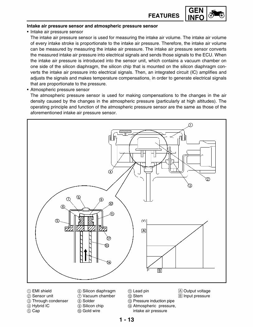
Intake air pressure sensor and atmospheric pressure sensor• Intake air pressure sensor
The intake air pressure sensor is used for measuring the intake air volume. The intake air volumeof every intake stroke is proportionate to the intake air pressure. Therefore, the intake air volumecan be measured by measuring the intake air pressure. The intake air pressure sensor convertsthe measured intake air pressure into electrical signals and sends those signals to the ECU. Whenthe intake air pressure is introduced into the sensor unit, which contains a vacuum chamber onone side of the silicon diaphragm, the silicon chip that is mounted on the silicon diaphragm con-verts the intake air pressure into electrical signals. Then, an integrated circuit (IC) amplifies andadjusts the signals and makes temperature compensations, in order to generate electrical signalsthat are proportionate to the pressure.
• Atmospheric pressure sensorThe atmospheric pressure sensor is used for making compensations to the changes in the airdensity caused by the changes in the atmospheric pressure (particularly at high altitudes). Theoperating principle and function of the atmospheric pressure sensor are the same as those of theaforementioned intake air pressure sensor.
1 EMI shield2 Sensor unit3 Through condenser4 Hybrid IC5 Cap
6 Silicon diaphragm7 Vacuum chamber8 Solder9 Silicon chip0 Gold wire
A Lead pinB StemC Pressure induction pipeD Atmospheric pressure,
intake air pressure
È Output voltageÉ Input pressure

1 - 14
GENINFOFEATURES
Coolant temperature sensorThe signals from the coolant temperature sensor are used primarily for making fuel volume compen-sations during starting and warm-up. The coolant temperature sensor converts the temperature ofthe coolant into electrical signals and sends them to the ECU.This sensor uses a semi-conductor thermistor that has a large resistance at low temperatures and asmall resistance at high temperatures. The thermistor converts the temperature-dependent changesin resistance into electrical resistance values, which are then input into the ECU.
1 Connector2 Terminal
3 Tube4 Thermistor
5 Holder È Resistance kΩÉ Temperature °C (°F)
Intake temperature sensorThe intake temperature sensor corrects the deviation of the air-fuel mixture that is associated withthe changes in the intake air density, which are created by the changes in the intake air temperaturethat occur due to atmospheric temperatures. This sensor uses a semi-conductor thermistor that hasa large resistance at low temperatures and a small resistance at high temperatures. The thermistorconverts the temperature-dependent changes in resistance into electrical resistance values, whichare then input into the ECU.
1 Connector2 Terminal3 Tube4 Thermistor
5 Holder
È Resistance kΩÉ Temperature °C (°F)

1 - 15
GENINFOFEATURES
Lean angle cut-off switchThe lean angle cut-off switch stops the supply of fuel to the engine in case the motorcycle overturns.When the motorcycle is in the normal state, the cut-off switch outputs a constant voltage of approxi-mately 1.0 V (low level). When the motorcycle tilts, the float in the switch tilts in proportion to the tiltof the motorcycle. However, the voltage output to the ECU remains unchanged at the low level.When the tilt of the motorcycle exceeds 65 degrees (according to the tilt of the float), the signal fromthe sensor increases to approximately 4.0 V (high level). When the ECU receives the high-level volt-age, it determines that the motorcycle has overturned, and stops the delivery of fuel to the engine byturning OFF the fuel injection system relay that powers the fuel pump and the injectors. Once thecut-off switch is tripped, the ECU maintains this state; therefore, even if the motorcycle has recov-ered its upright position, this state will not be canceled unless the main switch is turned OFF, andthen turned back ON.
È Output voltageÉ High levelÊ Low levelË Cut-off switch tilt angleÌ Fuel injection system relay OFF

1 - 16
GENINFOFEATURES
FUEL INJECTION SYSTEMOperation and controlThe fuel injection timing, injection duration, ignition timing, and the coil energizing duration are con-trolled by the ECU. To determine the basic injection timing, the ECU calculates the intake air volumethrough the signals from the intake air pressure sensor, throttle position sensor, cylinder identifica-tion sensor, and crankshaft position sensor.Furthermore, the ECU calculates the final injection timing by adding the following compensations tothe aforementioned basic injection duration: those obtained from the state of acceleration, as wellas those based on the signals from various sensors such as the coolant temperature, intake tem-perature and atmospheric. At the same time, the ECU assesses the crankshaft position through thesignals from the cylinder identification sensor and the crankshaft position sensor. Then, when theECU determines that it is time to inject fuel, it sends an injection command to the injectors. Further-more, the ECU also controls the length of time the coil is energized by calculating the ignition timingand the coil energizing duration based on the signals from these sensors.Determining the basic injection durationThe intake air volume determines the basic injection duration. In order to operate the engine in anoptional condition, it is necessary to supply fuel at an air-fuel ratio that corresponds appropriately tothe volume of intake air that is constantly changing, and to ignite it an appropriate timing. The ECUcontrols the basic injection duration based on the intake air volume and engine speed data.
Composition of basic injection duration
È RPMÉ Injection durationÊ Cranking
Ë Warm-upÌ IdleÍ Acceleration
Î ConstantÏ DecelerationÐ Start
Ñ After startÒ Basic injection durationÓ Voltage compensation
duration
Detection of intake air volumeThe intake air volume is detected primarily through the signals from the throttle position sensor andthe intake air pressure sensor. The intake air volume is determined in accordance with the signalsfrom the atmospheric pressure sensor, intake temperature sensor, and the engine speed data.

1 - 17
GENINFOFEATURES
Determining the final injection durationThe intake air volume determines the basic injection duration. However, at a given intake air vol-ume, the volume of fuel that is required varies by the engine operating conditions such as accelera-tion or deceleration, or by weather conditions. This system uses various sensors to precisely checkthese conditions, applies compensations to the basic injection duration, and determines the finalinjection duration based on the operating condition of the engine.
Composition of final injection duration
1 Injection at start *12 After-start enrichment *23 Warm-up enrichment *34 Acceleration compensation *55 Fuel cut-off
Deceleration compensation *5
6 Basic injection duration7 Voltage compensation duration
È RPMÉ Injection durationÊ CrankingË Warm-up
Ì IdleÍ AccelerationÎ ConstantÏ DecelerationÐ StartÑ After start
Intake air pressure
Engine rpm
Close or open of throttle
Basic injection quantity Compensation
Injection command
Watertemperature
Intake airtemperature
Atmosphericpressure
Battery voltage

1 - 18
GENINFOFEATURES
Reactive injection duration:A lag is created between the time the ECU outputs a fuel injection signal to the injector and the timethe injector actually opens. Therefore, the ECU calculates this lag in advance before sending theactuation signal to the injector. The battery voltage determines the reactive injection duration.• High voltage → short reactive injection duration• Low voltage → long reactive injection duration
LIST OF FUEL INJECTION COMPENSATIONS
• Over-revving controlThis function effects fuel cut-off control when the engine speed becomes greater than the pre-scribed value. The fuel cut-off control regulates the engine speed by stopping the injection of fuelinto two cylinders when the engine speed becomes greater than the specified value. If the enginespeed increases further, this control stops the injection of fuel to all the cylinders. Thus, the over-revving control effects fuel cut-off control in two stages.
Compensation item Check item Sensor used
Starting injection *1 Coolant temperature Coolant temperature sensor
After-start injection:
After-start enrichment *2 Coolant temperature Coolant temperature sensor
Warm-up enrichment *3 Coolant temperature Coolant temperature sensor
Intake temperature compensation *4 Intake temperature Intake temperature sensor
Acceleration compensation/decelera-tion compensation *5
Intake air pressure Intake air pressure sensor
Throttle position Throttle position sensor
Coolant temperature Coolant temperature sensor

1 - 19
GENINFOFEATURES
THREE-WAY CATALYTIC CONVERTER SYSTEMSystem outlineThis is a highly efficient exhaust gas cleaning system that effects air-fuel control through a jointeffort by the FI system and the three-way catalytic converter system. By effecting comprehensivecontrol of the air-fuel ratio in this manner, this system reduces the CO, HC, and NOx in the exhaustgases.The FI system controls the mixture to an optimal air-fuel ratio (basic air-fuel ratio) that matches theoperating condition of the engine in order to realize an ideal combustion.Through the joint effort of these control systems, the exhaust gas is cleaned in a highly efficientmanner without sacrificing engine performance.
Three-way catalytic converter system diagram
1 Ignition coil2 Injector3 Intake temperature
sensor4 Throttle position sensor
5 Intake air pressure sensor
6 Crankshaft position sensor
7 Coolant temperature sensor
8 Cylinder identification sensor
9 Spark plug0 ECUA Igniter
B Atmospheric pressure sensor
C Catalytic converter

1 - 20
GENINFOFEATURES
INSTRUMENT FUNCTIONMulti-function displayThe multi-function display is equipped with thefollowing:• a speedometer (which shows the riding
speed)• an odometer (which shows the total dis-
tance traveled)• two tripmeters (which show the distance
traveled since they were last set to zero)• a fuel reserve tripmeter (which shows the
distance traveled since the fuel level warn-ing light came on)
• a clock• a self-diagnosis device• a display brightness and engine speed
warning light control mode
NOTE:_
• Be sure to turn the key to “ON” before using the “SELECT” and “RESET” buttons.• For the U.K. only: To switch the speedometer display between kilometers and miles, press the
“SELECT” button and “RESET” button together for at least two seconds.
Odometer and tripmeter modesPushing the “SELECT” button switches the display between the odometer mode “ODO” and the trip-meter modes “TRIP A” and “TRIP B” in the following order:ODO → TRIP A → TRIP B → ODOIf the fuel level warning light comes on, the odometer display will automatically change to the fuelreserve tripmeter mode “F-TRIP” and start counting the distance traveled from that point. In thatcase, pushing the “SELECT” button switches the display between the various tripmeter and odome-ter modes in the following order:F-TRIP → TRIP A → TRIP B → ODO → F-TRIPTo reset a tripmeter, select it by pushing the “SELECT” button, and then push the “RESET” buttonfor at least one second. If you do not reset the fuel reserve tripmeter manually, it will reset itselfautomatically and the display will return to the prior mode after refueling and traveling 5 km.Clock modeTurn the key to “ON”.To change the display to the clock mode, push the “SELECT” button for at least one second.To change the display back to the prior mode, push the “SELECT” button.To set the clock:1. Push the “SELECT” button and “RESET” button together for at least two seconds.2. When the hour digits start flashing, push the “RESET” button to set the hours.3. Push the “SELECT” button, and the minute digits will start flashing.4. Push the “RESET” button to set the minutes.5. Push the “SELECT” button and then release it to start the clock.Self-diagnosis deviceThis model is equipped with a self-diagnosis device for various electrical circuits.If any of those circuits are defective, the engine trouble warning light will come on and then, themulti-function display will indicate a two-digit error code (e.g., 11, 12, 13).
1 Multi-function display2 “SELECT” button3 “RESET” button4 Engine trouble warning light

1 - 21
GENINFOFEATURES
Display brightness and engine speed indi-cator light control modeThis mode cycles through five control func-tions, allowing you to make the following set-tings in the order listed below.1. Display brightness: This function allows you
to adjust the brightness of the multi-functiondisplay to suit the outside lighting condi-tions.
2. Engine speed indicator light activity: Thisfunction allows you to choose whether ornot the indicator light should be activatedand whether it should blink or stay on whenactivated.
3. Engine speed indicator light activation: Thisfunction allows you to select the enginespeed at which the indicator light will beactivated.
4. Engine speed indicator light deactivation: This function allows you to select the engine speed atwhich the indicator light will be deactivated.
5. Engine speed indicator light brightness: This function allows you to adjust the brightness of theindicator light to suit your preference.
NOTE:_
• To make any settings in this mode, you have to cycle through all of its functions. However, if thekey is turned to “OFF” before completing the procedure, only the settings made before the“SELECT” button was last pushed will be applied.
• In this mode, the multi-function display shows the current setting for each function (except theengine speed indicator light activity function).
To adjust the display brightness1. Turn the key to “OFF”.2. Push and hold the “SELECT” button.3. Turn the key to “ON”, and then, after five seconds, release the “SELECT” button.4. Push the “RESET” button to select the desired display brightness level.5. Push the “SELECT” button to confirm the selected display brightness level. The control mode
changes to the engine speed indicator light activity function.
To set the engine speed indicator light activity function1. Push the “RESET” button to select one of the following indicator light activity settings:a. The indicator light will stay on when activated. (This setting is selected when the indicator light
stays on.)b. The indicator light will flash when activated. (This setting is selected when the indicator light
flashes four times per second.)c. The indicator light is deactivated; in other words, it will not come on or flash. (This setting is
selected when the indicator light flashes once every two seconds.)2. Push the “SELECT” button to confirm the selected indicator light activity. The control mode
changes to the engine speed indicator light activation function.
1 Engine speed indicator light2 “SELECT” button3 “RESET” button

1 - 22
GENINFOFEATURES
To set the engine speed indicator light activation function
NOTE:_
The indicator light activation function can be set between 7,000 and 12,000 r/min in increments of500 r/min.
1. Push the “RESET” button to select the desired engine speed for activating the indicator light.2. Push the “SELECT” button to confirm the selected engine speed.
The control mode changes to the engine speed indicator light deactivation function.
To set the engine speed indicator light deactivation function
NOTE:_
• The indicator light deactivation function can be set between 7,000 and 12,000 r/min in incrementsof 500 r/min.
• Be sure to set the deactivation function to a higher engine speed than for the activation function,otherwise the engine speed indicator light will remain deactivated.
1. Push the “RESET” button to select the desired engine speed for deactivating the indicator light.2. Push the “SELECT” button to confirm the selected engine speed.
The control mode changes to the engine speed indicator light brightness function.
To adjust the engine speed indicator light brightness1. Push the “RESET” button to select the desired indicator light brightness level.2. Push the “SELECT” button to confirm the selected indicator light brightness level. The multi-func-
tion display will return to the odometer, tripmeter or clock mode.

1 - 23
GENINFOIMPORTANT INFORMATION
EAS00020
IMPORTANT INFORMATIONPREPARATION FOR REMOVAL AND DISASSEMBLY1. Before removal and disassembly, remove all
dirt, mud, dust and foreign material. 2. Use only the proper tools and cleaning
equipment. Refer to the “SPECIAL TOOLS”.
3. When disassembling, always keep matedparts together. This includes gears, cylin-ders, pistons and other parts that have been“mated” through normal wear. Mated partsmust always be reused or replaced as anassembly.
4. During disassembly, clean all of the partsand place them in trays in the order of dis-assembly. This will speed up assembly andallow for the correct installation of all parts.
5. Keep all parts away from any source of fire.
EAS00021
REPLACEMENT PARTSUse only genuine Yamaha parts for allreplacements. Use oil and grease recom-mended by Yamaha for all lubrication jobs.Other brands may be similar in function andappearance, but inferior in quality.
EAS00022
GASKETS, OIL SEALS AND O-RINGS1. When overhauling the engine, replace all
gaskets, seals and O-rings. All gasket sur-faces, oil seal lips and O-rings must becleaned.
2. During reassembly, properly oil all matingparts and bearings and lubricate the oil seallips with grease.
lip
oil
lipspring
grease

1 - 24
GENINFOIMPORTANT INFORMATION
EAS00023
LOCK WASHERS/PLATES AND COTTER PINSAfter removal, replace all lock washers/plates1 and cotter pins. After the bolt or nut hasbeen tightened to specification, bend the locktabs along a flat of the bolt or nut.
EAS00024
BEARINGS AND OIL SEALSInstall bearings and oil seals so that the manu-facturer’s marks or numbers are visible. Wheninstalling oil seals, lubricate the oil seal lipswith a light coat of lithium-soap-based grease.Oil bearings liberally when installing, if appro-priate.1 Oil seal
CAUTION:_
Do not spin the bearing with compressedair because this will damage the bearingsurfaces.
1 Bearing
EAS00025
CIRCLIPSBefore reassembly, check all circlips carefullyand replace damaged or distorted circlips.Always replace piston pin clips after one use.When installing a circlip 1, make sure thesharp-edged corner 2 is positioned oppositethe thrust 3 that the circlip receives.4 Shaft

1 - 25
GENINFOCHECKING THE CONNECTIONS
EAS00026
CHECKING THE CONNECTIONSCheck the leads, couplers, and connectors forstains, rust, moisture, etc.1. Disconnect: • lead • coupler • connector
2. Check: • lead • coupler • connector
Moisture → Dry with an air blower. Rust/stains → Connect and disconnect sev-eral times.
3. Check:• all connections
Loose connection → Connect properly.
NOTE:_
If the pin 1 on the terminal is flattened, bend itup.
4. Connect: • lead • coupler • connector
NOTE:_
Make sure all connections are tight.
5. Check: • continuity
(with the pocket tester)
NOTE:_
• If there is no continuity, clean the terminals. • When checking the wire harness, perform
steps (1) to (3). • As a quick remedy, use a contact revitalizer
available at most part stores.
Pocket tester YM-03112

1 - 26
GENINFOSPECIAL TOOLS
EAS00027
SPECIAL TOOLSThe following special tools are necessary for complete and accurate tune-up and assembly. Useonly the appropriate special tools as this will help prevent damage caused by the use of inappropri-ate tools or improvised techniques. Special tools, part numbers or both may differ depending on thecountry. When placing an order, refer to the list provided below to avoid any mistakes.
Tool No. Tool name/Function Illustration
YM-01080-A
Flywheel puller
This tool is used to remove the genera-tor rotor.
YU-01235
Rotor holding tool
This tool is used to hold the generator rotor when removing or installing the generator rotor bolt or pickup coil rotor bolt.
YU-01304
Piston pin puller
This tool is used to remove the piston pins.
YU-01312-A
Fuel level gauge
This tool is used to measure the fuel level in the float chamber.
Radiator cap testerYU-24460-01
AdapterYU-33984
Radiator cap testerRadiator cap tester adapter
These tools are used to check the cool-ing system.
YU-33975
Steering nut wrench
This tool is used to loosen or tighten the steering stem ring nuts.
YM-1423
Damper rod holder
This tool is used to hold the damper rod assembly when loosening or tightening the damper rod assembly bolt.

1 - 27
GENINFOSPECIAL TOOLS
YU-38411
Oil filter wrench
This tool is needed to loosen or tighten the oil filter cartridge.
YM-01434
Rod holder
This tool is used to support the damper adjusting rod.
Rod pullerYM-01437
Rod puller
These tools are used to pull up the front fork damper rod.
YM-01441
Fork spring compressor
This tool is used to disassemble or assemble the front fork legs.
YM-01442
Fork seal driver
This tool is used to install the front fork’s oil seal and dust seal.
YU-08030
Carburetor synchronizer
This guide is used to synchronize the carburetors.
Compression gaugeYU-33223Adapter
YU-33223-3
Compression gaugeCompression gauge adapter
These tools are used to measure engine compression.
Valve spring compressorYM-04019AttachmentYM-4108YM-4114
Valve spring compressorValve spring compressor attachment
These tools are used to remove or install the valve assemblies.
Tool No. Tool name/Function Illustration

1 - 28
GENINFOSPECIAL TOOLS
Middle driven shaft bearing driver
YM-4058-1Mechanical seal
installerYM-33221
Middle driven shaft bearing driverMechanical seal installer
These tools are used to install the water pump seal.
YM-91042
Universal clutch holder
This tool is used to hold the clutch boss when removing or installing the clutch boss nut.
(4 mm, 0.16 in)90890-04111
(4.5 mm, 0.18 in)YM-4116
Valve guide remover
This tool is used to remove or install the valve guides.
(4 mm, 0.16 in)90890-04112
(4.5 mm, 0.18 in)YM-4117
Valve guide installer
This tool is used to install the valve guides.
(4 mm, 0.16 in)90890-04113
(4.5 mm, 0.18 in)YM-4118
Valve guide reamer
This tool is used to rebore the new valve guides.
YM-34487
Dynamic spark tester
This tool is used to check the ignition system components.
ACC-11001-05-01
Quick Gasket®
This bond is used to seal two mating surfaces (e.g., crankcase mating sur-faces).
YM-01471
Pivot shaft wrench
This tool is need to loosen or tighten the spacer bolt.
Tool No. Tool name/Function Illustration

1 - 29
GENINFOSPECIAL TOOLS
YM-03112
Pocket tester
This instrument is needed for checking the engine oil temperature.
YB-35956
Mity vac
This tool used to measure the vacuum pressure.
YM-8037
Piston ring compressor
This tool is used to compress the piston rings when installing the piston into the cylinder.
YM-03176
Fuel pressure adapter
This tool is needed to measure fuel pressure.
YU-03153
Pressure gauge
This tool used is to measure fuel pres-sure.
90890-03158
Carburetor angle driver
This tool is used to turn the air screw when synchronizing the throttle bodies.
Tool No. Tool name/Function Illustration