yrc1000micro options instructions€¦ · each robot axis on the programming pendant. the pp...
TRANSCRIPT

MANUAL NO.
HW1484486 1
YRC1000micro OPTIONSINSTRUCTIONSFOR PENDANT OSCILLOSCOPE FUNCTION
Upon receipt of the product and prior to initial operation, read these instructions thoroughly, and retain for future reference.
MOTOMAN INSTRUCTIONS
MOTOMAN- INSTRUCTIONSYRC1000micro INSTRUCTIONSYRC1000micro OPERATOR’S MANUAL YRC1000micro MAINTENANCE MANUAL YRC1000micro ALARM CODES (MAJOR ALARMS) (MINOR ALARMS)
1/55
181289-1CD1

HW1484486
DANGER
• This manual explains the pendant oscilloscope function of the YRC1000micro system. Read this manual carefully and be sure to understand its contents before handling the YRC1000micro. Any matter not described in this manual must be regarded as “prohibited” or “improper”.
• General information related to safety are described in “Chapter 1. Safety” of the YRC1000micro INSTRUCTIONS. To ensure correct and safe operation, carefully read “Chapter 1. Safety” of the YRC1000micro INSTRUCTIONS.
CAUTION
• In some drawings in this manual, protective covers or shields are removed to show details. Make sure that all the covers or shields are installed in place before operating this product.
• YASKAWA is not responsible for incidents arising from unauthorized modification of its products. Unauthorized modification voids the product warranty.
NOTICE
• The drawings and photos in this manual are representative examples and differences may exist between them and the delivered product.
• YASKAWA may modify this model without notice when necessary due to product improvements, modifications, or changes in specifications. If such modification is made, the manual number will also be revised.
• If your copy of the manual is damaged or lost, contact a YASKAWA representative to order a new copy. The representatives are listed on the back cover. Be sure to tell the representative the manual number listed on the front cover.
ii HW1484486 2/55

HW1484486
Notes for Safe OperationRead this manual carefully before installation, operation, maintenance, or inspection of the YRC1000micro.
In this manual, the Notes for Safe Operation are classified as “DANGER”, “WARNING”, “CAUTION”, or “NOTICE”.
Even items described as “CAUTION” may result in a serious accident in some situations. At any rate, be sure to follow these important items.
DANGERIndicates an imminently hazardous situation which, if not avoided, will result in death or serious injury. Safety Signs identified by the signal word DANGER should be used sparingly and only for those situations presenting the most serious hazards.
WARNINGIndicates a potentially hazardous situation which, if not avoided, will result in death or serious injury. Hazards identified by the signal word WARNING present a lesser degree of risk of injury or death than those identified by the signal word DANGER.
CAUTIONIndicates a hazardous situation, which if not avoided, could result in minor or moderate injury. It may also be used without the safety alert symbol as an alternative to “NOTICE”.
NOTICENOTICE is the preferred signal word to address practices not related to personal injury. The safety alert symbol should not be used with this signal word. As an alternative to “NOTICE”, the word “CAUTION” without the safety alert symbol may be used to indicate a message not related to personal injury.
NOTETo ensure safe and efficient operation at all times, be sure to follow all instructions, even if not designated as “DAN-GER”, “WARNING” and “CAUTION".
iii HW1484486 3/55

HW1484486
DANGER
• Before operating the manipulator, make sure the servo power is turned OFF by performing the following operations. When the servo power is turned OFF, the SERVO ON LED on the programming pendant is turned OFF.– Press the emergency stop button on the programming pendant or
on the external control device, etc.– Disconnect the safety plug of the safety fence.
(when in the play mode or in the remote mode)If operation of the manipulator cannot be stopped in an emergency, personal injury and/or equipment damage may result.
Fig. : Emergency Stop Button
• Before releasing the emergency stop, make sure to remove the obstacle or error caused the emergency stop, if any, and then turn the servo power ON.
Failure to observe this instruction may cause unintended movement of the manipulator, which may result in personal injury.
Fig. : Release of Emergency Stop
TURN
• Observe the following precautions when performing a teaching operation within the manipulator's operating range:– Be sure to perform lockout by putting a lockout device on the
safety fence when going into the area enclosed by the safety fence. In addition, the operator of the teaching operation must display the sign that the operation is being performed so that no other person closes the safety fence.
– View the manipulator from the front whenever possible.
– Always follow the predetermined operating procedure.
– Always keep in mind emergency response measures against the manipulator’s unexpected movement toward a person.
– Ensure a safe place to retreat in case of emergency.
Failure to observe this instruction may cause improper or unintended movement of the manipulator, which may result in personal injury.
• Confirm that no person is present in the manipulator's operating range and that the operator is in a safe location before:
– Turning ON the YRC1000micro power
– Moving the manipulator by using the programming pendant
– Running the system in the check mode
– Performing automatic operations
Personal injury may result if a person enters the manipulator's operating range during operation. Immediately press an emergency stop button whenever there is a problem. The emergency stop button is located on the right of the programming pendant.
• Read and understand the Explanation of the Warning Labels before operating the manipulator.
iv HW1484486 4/55

HW1484486
DANGER
• In the case of not using the programming pendant, be sure to supply the emergency stop button on the equipment. Then before operating the manipulator, check to be sure that the servo power is turned OFF by pressing the emergency stop button. Connect the external emergency stop button to the 4-14 pin and 5-15 pin of the Safety connector (Safety) .
• Upon shipment of the YRC1000micro, this signal is connected by a jumper cable in the dummy connector. To use the signal, make sure to supply a new connector, and then input it.
If the signal is input with the jumper cable connected, it does not function, which may result in personal injury or equipment damage.
WARNING
• Perform the following inspection procedures prior to conducting manipulator teaching. If there is any problem, immediately take necessary steps to solve it, such as maintenance and repair.
– Check for a problem in manipulator movement.
– Check for damage to insulation and sheathing of external wires.
• Return the programming pendant to a safe place after use.
If the programming pendant is left unattended on the manipulator, on a fixture, or on the floor, etc., the Enable Switch may be activated due to surface irregularities of where it is left, and the servo power may be turned ON. In addition, in case the operation of the manipulator starts, the manipulator or the tool may hit the programming pendant left unattended, which may result in personal injury and/or equipment damage.
v HW1484486 5/55

HW1484486
Definition of Terms Used Often in This ManualThe MOTOMAN is the YASKAWA industrial robot product.
The MOTOMAN usually consists of the manipulator, the YRC1000micro controller, manipulator cables, the YRC1000micro programming pendant (optional), and the YRC1000micro programming pendant safety signal short circuit connector (optional).
In this manual, the equipment is designated as follows:
Equipment Manual Designation
YRC1000micro controller YRC1000micro
YRC1000micro programming pendant Programming pendant (optional)
Cable between the manipulator and the controller
Manipulator cable
YRC1000micro programming pendant safety signal short circuit connector
Programming pendant safety signal short circuit connector (optional)
vi HW1484486 6/55

HW1484486
Descriptions of the programming pendant keys, buttons, and displays are shown as follows:
Equipment Manual Designation
ProgrammingPendant
Character Keys /Symbol Keys
The keys which have characters or symbols printed on them are denoted with [ ].e.g. [ENTER]
Axis Keys/Numeric Keys
[Axis Key] and [Numeric Key] are generic names for the keys for axis operation and number input.
Keys pressed simultaneously
When two keys are to be pressed simultaneously, the keys are shown with a “+” sign between them, e.g. [SHIFT]+[COORD].
Mode Switch Mode Switch can select three kinds of modes that are denoted as follows: REMOTE, PLAY or TEACH. (The switch names are denoted as symbols)
Button The three buttons on the upper side of the programming pendant are denoted as follows: START, HOLD, or EMERGENCY STOP. (The button names are denoted as symbols)
Displays The menu displayed in the programming pendant is denoted with { }.e.g. {JOB}
EMERGENCY STOP
Numeric keys
Axis keys
Enter key
Mode switch*
Start button* Hold button*
Emergency stop button
Shift key
Page keyCoordinate key
PLAY
REMOTE
TEACH
START
*The button/switch names are denoted as symbols.
HOLD
vii HW1484486 7/55

HW1484486
Description of the Operation ProcedureIn the explanation of the operation procedure, the expression "Select • • • " means that the cursor is moved to the object item and [SELECT] is pressed, or that the item is directly selected by touching the screen.
Registered TrademarkIn this manual, names of companies, corporations, or products are trademarks, registered trademarks, or brand names for each company or corporation. The indications of (R) and TM are omitted.
viii HW1484486 8/55

Contents
HW1484486
1 Overview......................................................................................................................................... 1-1
1.1 Pendant Oscilloscope Function ......................................................................................... 1-1
1.2 Specification ...................................................................................................................... 1-2
1.3 Setup ................................................................................................................................. 1-2
2 Setting and Operation for Data Measurement ................................................................................ 2-1
2.1 Startup of Pendant Oscilloscope Function......................................................................... 2-1
2.2 Main Screen Configuration ................................................................................................ 2-2
2.2.1 Main Screen (Not In-Measurement Mode) ........................................................... 2-2
2.2.2 Main Screen (In-Measurement Mode).................................................................. 2-3
2.3 Setting Measurement Conditions....................................................................................... 2-4
2.3.1 Channel Setting Window ...................................................................................... 2-4
2.3.2 CH Display Setting Panel ..................................................................................... 2-7
2.3.3 TimeScale Setting Panel ...................................................................................... 2-9
2.3.4 Trigger Setting Panel.......................................................................................... 2-10
2.4 Starting and Ending Measurement .................................................................................. 2-14
2.4.1 Continuous Mode ............................................................................................... 2-14
2.4.2 Trigger Mode ...................................................................................................... 2-15
2.5 Termination and Minimization of Pendant Oscilloscope Function ................................... 2-16
2.5.1 Termination of PP Oscilloscope ......................................................................... 2-16
2.5.2 Minimizing PP Oscilloscope Application............................................................. 2-16
3 Saving and Loading the Measurement Data................................................................................... 3-1
3.1 SaveMode Setting Panel ................................................................................................... 3-1
3.1.1 Data File Name and Save Destination ................................................................. 3-2
3.1.2 CSV File ............................................................................................................... 3-3
3.2 Load Panel ........................................................................................................................ 3-4
4 Other Functions .............................................................................................................................. 4-1
4.1 Zoom Function................................................................................................................... 4-1
4.1.1 During Execution of Zoom Function ..................................................................... 4-2
4.2 Cursor Measurement Function .......................................................................................... 4-3
4.2.1 Cursor Measurement Parameters ........................................................................ 4-5
4.3 Job Step No. Saving Function ........................................................................................... 4-6
4.3.1 Channel Setting.................................................................................................... 4-7
4.3.2 Adjustment of Acquisition Time of Job Name and Step No.................................. 4-7
ix HW1484486 9/55

Contents
HW1484486
4.4 Operation Function by Dedicated Input ............................................................................. 4-9
4.4.1 Dedicated Input Signal.......................................................................................... 4-9
4.4.2 Dedicated Output Signal..................................................................................... 4-11
4.5 Simultaneous Display of Waveform Display Area and Reading Job ............................... 4-13
4.5.1 Displaying Method ..............................................................................................4-13
4.5.2 Display Items ...................................................................................................... 4-15
4.5.3 Operating Methods .............................................................................................4-16
4.5.4 When in 3D Graphical Display Function .............................................................4-18
5 Supplementary Explanation ............................................................................................................5-1
5.1 Division [div]: Unit for Measurement Screen Position ........................................................ 5-1
5.2 Reference Unit ...................................................................................................................5-2
6 Error Messages............................................................................................................................... 6-1
x HW1484486 10/55

1 Overview1.1 Pendant Oscilloscope Function
HW1484486
1 Overview
1.1 Pendant Oscilloscope Function
Pendant Oscilloscope Function (hereinafter referred to as “PP oscilloscope”) is the monitoring function of speed reference, torque reference, encoder temperature, as well as of concurrent I/O signals of each robot axis on the Programming Pendant. The PP oscilloscope is configured by the software, which requires no special hardware equipment. By carrying out the PP oscilloscope function, the pendant oscilloscope application (hereinafter referred to as “PP oscilloscope application”) starts on the Programming Pendant.
Equipped with an integral display screen containing the waveform display window and the condition setting panel, the PP oscilloscope application enables to perform several processes from condition setting to measurement at a time. Other available functions include Trigger function that stops the data acquisition at a given condition, Measure and display function of maximum/minimum values after data acquisition, Zoom function that displays the waveform data in a magnified view, and data output function in a format available on the computer. fig. 1-1 “Display of PP Oscilloscope” shows a typical display of PP oscilloscope.
Fig. 1-1: Display of PP Oscilloscope
Programmingpendant
Waveform display area
Condition setting panel
1-1 HW1484486 11/55

1 Overview1.2 Specification
HW1484486
1.2 Specification
Main specification of the PP oscilloscope is listed in table 1-1 “Main Specifications of PP Oscilloscope” below:
1.3 Setup
To activate the function, the optional parameters of the pendant oscilloscope function need to be effective (note that the user cannot change the parameter setting). For the parameter setting other than specified above, contact a YASKAWA sales representative.
Table 1-1: Main Specifications of PP Oscilloscope
Parameter Specification Description
Measurement data type
Speed reference, Speed FB, Torque reference, Encoder temperature, Concurrent I/O signal,Register value
Number of channels that can be measured at the same time.
Maximum channel number
10 channels Number of channels that can be measured at the same time.
Sampling time 2.0, 4.0, 8.0, 16.0, 32.0, 64.0 [ms]
Indicates time interval for data sampling. Smaller values enable more detailed measurement data, but shorten the data record time due to much data volume.
Maximum data length 20 [s] to 100 [s] Indicates data length that can be recorded at a measurement. Some setting of sampling time can limit the maximum data length available.
Waveform acquisition mode
Continuous modeTrigger mode
Selects the mode according to the Trigger state (valid/invalid):○Trigger Invalid: ContinuousThe Continuous mode displays the acquired data in a time-series order.○Trigger Valid: TriggerThe Trigger mode automatically stops the measurement and displays waveform when the trigger conditions are satisfied.
Trigger condition ○Trigger for measurement waveform
- Up trigger - Down trigger - Up&Down trigger○Alarm trigger
Other than normal waveform triggers, alarm trigger is also included.
Data saving format CSV JPG
Saves the acquired data in SD or USB memory with the CSV (Comma Separated Value) format.
Saves the displayed data on the screen in SD or USB memory with the JPG (Joint Photographic Experts Group) format.
1-2 HW1484486 12/55

2 Setting and Operation for Data Measurement2.1 Startup of Pendant Oscilloscope Function
HW1484486
2 Setting and Operation for Data Measurement
This chapter describes setting and operation required for the measurement.
Basically the PP oscilloscope is operated by touching on the screen; for pull-down selection box or entry box,
however, the Cursor Keys enable the cursor operation, and [SELECT], [ENTER] or [CANCEL] enables selection, determination, or cancel, just as the normal operation on the pendant screens.
In performing numerical input using an entry box, first activate the parameter to a selective state by [SELECT], input numerical values by the Number Keys of the pendant, and press [ENTER] to determine it. To cancel the input numerical values, press [CANCEL] in the selective state.
2.1 Startup of Pendant Oscilloscope Function
The PP oscilloscope can be started up by the following step:
1. Select {ROBOT} from the menu in the left of screen.
2. Select {PENDANT OSCILLOSCOPE} from the expanded menu (see fig. 2-1 “PP Oscilloscope Startup Menu” ).
Fig. 2-1: PP Oscilloscope Startup Menu
2-1 HW1484486 13/55
2 Setting and Operation for Data Measurement2.2 Main Screen Configuration
HW1484486
2.2 Main Screen Configuration
Here explains the configuration of the Main screen.
The PP oscilloscope is displayed on the entire screen of Programming Pendant. The main screen has two types of modes; in-measurement and without not in-measurement (Waiting), in which functions or availability of some buttons are changed. Condition setting is only available in not in-measurement mode (Waiting).
2.2.1 Main Screen (Not In-Measurement Mode)
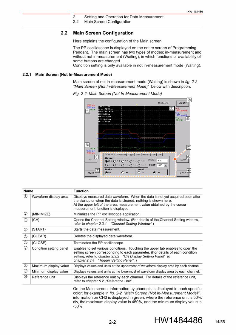
Main screen of not in-measurement mode (Waiting) is shown in fig. 2-2 “Main Screen (Not In-Measurement Mode)” below with description.
Fig. 2-2: Main Screen (Not In-Measurement Mode)
On the Main screen, information by channels is displayed in each specific color; for example in fig. 2-2 “Main Screen (Not In-Measurement Mode)” , information on CH3 is displayed in green, where the reference unit is 50%/div, the maximum display value is 450%, and the minimum display value is -50%.
Name Function
Waveform display area Displays measured data waveform. When the data is not yet acquired soon after the startup or when the data is cleared, nothing is shown here. At the upper left of the area, measurement value obtained by the cursor measurement function is displayed.
{MINIMIZE} Minimizes the PP oscilloscope application.
{CH} Opens the Channel Setting window. (For details of the Channel Setting window, refer to chapter 2.3.1 “Channel Setting Window” )
{START} Starts the data measurement.
{CLEAR} Deletes the displayed data waveform.
{CLOSE} Terminates the PP oscilloscope.
Condition setting panel Enables to set various conditions. Touching the upper tab enables to open the setting screen corresponding to each parameter. (For details of each condition setting, refer to chapter 2.3.2 “CH Display Setting Panel” to chapter 2.3.4 “Trigger Setting Panel” .)
Maximum display value Displays values and units at the uppermost of waveform display area by each channel.
Minimum display value Displays values and units at the lowermost of waveform display area by each channel.
Reference unit Displays the reference unit by each channel. For details of the reference unit, refer to chapter 5.2 “Reference Unit” .
2-2 HW1484486 14/55

2 Setting and Operation for Data Measurement2.2 Main Screen Configuration
HW1484486
2.2.2 Main Screen (In-Measurement Mode)
Main screen of In-measurement mode is shown in fig. 2-3 “Main Screen (In-Measurement Mode)” . In this mode, the states of some buttons are changed. Here describes such buttons;
Fig. 2-3: Main Screen (In-Measurement Mode)
Name Function
{STOP} Switched from {START}, stops the data measurement.
{CLEAR} In measurement mode, the button operation is disabled.
{CLOSE} In measurement mode, the button operation is disabled.
Condition setting panel In measurement mode, the operation on tab is disabled.
NOTE
Soon after switching the buttons {START} / {STOP}, button operation is not available for a certain period of time to avoid continuous pressing of the buttons.
When the buttons {START} / {STOP} are disabled, wait until the operation becomes available.
2-3 HW1484486 15/55

2 Setting and Operation for Data Measurement2.3 Setting Measurement Conditions
HW1484486
2.3 Setting Measurement Conditions
Here describes how to set the measurement conditions on the channel setting window and the condition setting panel.
2.3.1 Channel Setting Window
Pressing {CH} on the Main screen opens the channel setting window. fig. 2-4 “Channel Setting Window” shows the typical display example of the channel setting window. On this window, data type for measurement at each channel, measurement target axis, and measurement interval of each data can be set.
Fig. 2-4: Channel Setting Window
Sampling time
Sets the sampling interval of the data to be acquired. Settable options are 2.0, 4.0, 8.0, 16.0, 32.0, and 64.0 [ms], each of which corresponds to the sampling frequencies of 500, 250, 125, 62.5, 31.25, and 15.625 [Hz], respectively.
Measurement valid/invalid check box
Requires setting for each channel, where the channel with a check mark becomes valid for measurement. When the multiple channels are to be valid, the channel numbers are not necessarily to be sequential.
Target
Requires setting for each channel, where the setting of output signal type is available. Servo: Enables to select the servo CPU signals at the option . I/O signal: Enables to input the concurrent I/O signal at the option . Register: Enables to input the register number at the option .
NOTEThe more the channels are available, the more the process is overloaded, and it affect the data updating speed in the waveform display area; it is recommended that unneces-sary channels, if any, should be set to invalid.
2-4 HW1484486 16/55

2 Setting and Operation for Data Measurement2.3 Setting Measurement Conditions
HW1484486
Signal selection
Requires setting for each channel. When {Servo} is selected at the option : Select speed reference, speed feedback, torque reference or encoder temperature. When {I/O signal} is selected at the option : Input signal number of concurrent I/O. For the details of concurrent I/O, refer to “YRC1000micro OPTIONS INSTRUCTIONS FOR Concurrent I/O (RE-CKI-A469).”
When {Register} is selected at the option : Input register number. Input the numerical value between M000 and M999.
Axis selection
Set the target axis for data acquisition. (Only when Servo is selected at option Target) One servo board (JANCD-ACP31-1E) can connect up to 8 motors. Furthermore, up to 2 servo boards can be connected to a system. This means that the maximum axis configuration on a system allows simultaneous connection of 16 axes of motors. The PP oscilloscope specifies the measurement target axis by the unique number of physical connection among these 16 axes. This is called as “physical axis connection”. Under the basic system configuration of a servo board, the physical axes 1 to 6 are occupied by robot axis, and external axes are connected to the physical axes 7 and 8. When every servo board is added, the number of physical axis is represented by offsetting each +9. This relationship is shown in the following table table 2-1 “Relationship between the number of servo board and the physical axis number” :
NOTE
Requirements on Concurrent I/O Signal
The concurrent I/O signal is updated in every 4.0 [ms]. Whereas when the PP oscilloscope allows the setting of sampling time as 8.0 [ms] or more, the measurement data has a delay time up to as long as that of the sampling time.
Even when the sampling time is 4.0 [ms], the signal turning ON/OFF only for 4.0 [ms] may have data skipped; ensure to keep the time interval of 20 [ms] or more between the signal ON and OFF for the measurement target of concurrent I/O signal.
Table 2-1: Relationship between the number of servo board and the physical axis number
No. of servo board Physical axis number of the board
SV#1 1 to 9
SV#2 10 to 18
2-5 HW1484486 17/55

2 Setting and Operation for Data Measurement2.3 Setting Measurement Conditions
HW1484486
The following example shows the typical specification of physical axis number in the main system configuration.
Example:
○6-axis robot, R1
○6-axis robot + external axis (R1 + S1 [2-axis] setting)
○7-axis robot + external axis (R1 + S1 [1-axis] setting)
{OK}
Closes the window with the change given on the channel setting window reflected. When there is a measured waveform at the waveform display area, the waveform data is cleared.
When no change has been given after the channel setting window is opened, this button acts just as {CANCEL}.
{CANCEL}
Closes the window without reflecting the change given on the channel setting window. The waveforms data is not cleared.
Target axis S L U R B T
Axis selection No. (R1)
1 4 3 6 2 5
Target axis S L U R B T
Axis selection No. (R1)
1 4 3 6 2 5
Target axis EX1 EX2
Axis selection No. (S1)
7 9
Target axis S L U R B T E
Axis selection No. (R1)
1 4 3 6 2 5 7
Target axis EX1
Axis selection No. (S1)
9
2-6 HW1484486 18/55
2 Setting and Operation for Data Measurement2.3 Setting Measurement Conditions
HW1484486
2.3.2 CH Display Setting Panel
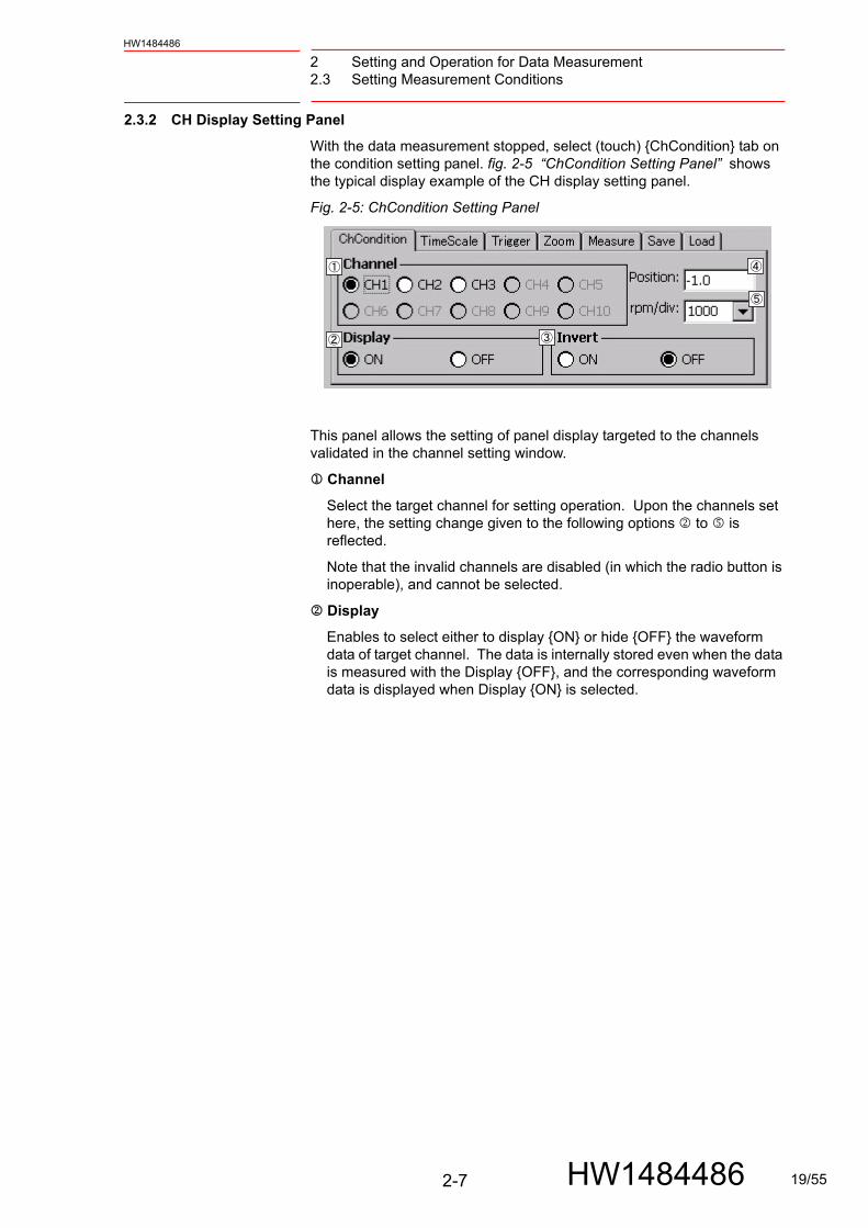
With the data measurement stopped, select (touch) {ChCondition} tab on the condition setting panel. fig. 2-5 “ChCondition Setting Panel” shows the typical display example of the CH display setting panel.
Fig. 2-5: ChCondition Setting Panel
This panel allows the setting of panel display targeted to the channels validated in the channel setting window.
Channel
Select the target channel for setting operation. Upon the channels set here, the setting change given to the following options to is reflected.
Note that the invalid channels are disabled (in which the radio button is inoperable), and cannot be selected.
Display
Enables to select either to display {ON} or hide {OFF} the waveform data of target channel. The data is internally stored even when the data is measured with the Display {OFF}, and the corresponding waveform data is displayed when Display {ON} is selected.
2-7 HW1484486 19/55

2 Setting and Operation for Data Measurement2.3 Setting Measurement Conditions
HW1484486
Invert
Enables to select either to invert the waveform data of target channel or not. Selecting Invert {ON} inverts the display of waveform data in a waveform display area between positive and negative. Selecting Invert {OFF} returns to the original state.
Position
Sets the zero position of target channel. Specify the zero point within the range of -5.0 to 5.0 [div] in the vertical axis of waveform display area.
On the extreme left of waveform display area, a marker is provided showing a zero point for each channel in which the current zero point can be confirmed (see fig. 2-6 “Zero Point Marker” ).
Fig. 2-6: Zero Point Marker
Unit (rpm/div, %/div, U/div)
Selects the reference unit of target channel in the vertical axis scale. (For description of the unit, refer to chapter 5.2 “Reference Unit” .)
Displayed unit and its selection depend on the signal output by the target channel.
Speed reference, Speed FB: Unit [rpm/div]: selectable among 250, 500, 1000, and 2000
Torque reference: Unit [%/div]: selectable among 3.3, 5, 6.6, 10, 33, 50, 66, and 100
Encoder temperature: Unit [°C/div]: selectable among 10, 20, and 40
Concurrent I/O signal: Unit [U/div]: selectable among 0.2, 0.5, 1.0, 2.0, 5.0, and 10.0
Register: Unit [-/div]: selectable among 1, 2, 5, 10, 20, 50, 100, 200, 500, 1000, 2000, 3277, 5000, 6554, 10000, 13107, 20000, 32768, 50000 and 65535.
Zero pointmaker
2-8 HW1484486 20/55

2 Setting and Operation for Data Measurement2.3 Setting Measurement Conditions
HW1484486
2.3.3 TimeScale Setting Panel
With the data measurement stopped, touch {TimeScale} tab on the condition setting panel. fig. 2-7 “TimeScale Setting Panel” shows the typical display example of TimeScale setting panel.
Fig. 2-7: TimeScale Setting Panel
ms/div
Sets the time for the horizontal axis of the waveform display area. The value selected here should be the time width [ms] per division of horizontal axis. Since there are 10 divisions in the entire horizontal axis, the eventual data length is 10 times of the specified value.
Selectable range of ms/div depends on the combination of sampling time set on the Channel Setting window:
With the sampling time of 2 [ms]:Up to 2000 [ms/div] (data length: 20 [s])
With the sampling time of 4 [ms]:Up to 5000 [ms/div] (data length: 50 [s])
With the sampling time of 8 [ms] or more: Up to 10000 [ms/div] (data length: 100 [s])
2-9 HW1484486 21/55

2 Setting and Operation for Data Measurement2.3 Setting Measurement Conditions
HW1484486
2.3.4 Trigger Setting Panel
With the data measurement stopped, select (touch) {Trigger} tab on the condition setting panel. fig. 2-8 “Trigger Setting Panel” shows the typical display example of Trigger setting panel.
This panel allows the setting of trigger function.
Fig. 2-8: Trigger Setting Panel
The trigger function is the function to automatically stop the measurement and display the waveform at the point where a certain condition is satisfied during the data measurement.
As trigger conditions, three options are available: when the target channel data exceeds or falls below the specified value (trigger level), or when any alarm occurs.
The data stop position is determined by Pre-trigger. The measurement result is displayed so that the position satisfying the trigger conditions becomes the Pre-trigger position. For example in fig. 2-9 “Outline of Trigger Function” , the data length is 10 [s] and the specified Pre-trigger is 3 [div] in horizontal axis. This allows the setting where the data before the trigger is acquired for 3 seconds, and the data after the trigger is acquired for 7 seconds.
Fig. 2-9: Outline of Trigger Function
CH
Select the channel as trigger target. Only the valid channel is selectable.
Data before Trigger 3[s]
Data length
Pre-trigger Data after Trigger 7[s]
Trigger level Zero point of waveform display
Zero point ofchannel
Horizontal axis
2-10 HW1484486 22/55

2 Setting and Operation for Data Measurement2.3 Setting Measurement Conditions
HW1484486
TrgType (Trigger type)
Select the trigger type to use. Selectable options are Up, Down, Up&Down, and Alarm.
When selecting Alarm, some of the setting parameters of Trigger Conditions are changed.
PreTrg (Pre-trigger)
Specify the pre-trigger position by the horizontal axis division (0 to 10.0).
Current pre-trigger position is shown by a marker on the upper part of the waveform display area (see fig. 2-10 “Pre-trigger Marker” ).
Fig. 2-10: Pre-trigger Marker
Table 2-2: Characteristics of Trigger Type
Trigger type Trigger condition
Up When the trigger target channel data exceeds the trigger level
Down When the trigger target channel data falls below the trigger level
Up&Down When the trigger target channel data is either over or below the trigger level
Alarm When the alarm assigned to alarm number occurs
Pre-triggermaeker
2-11 HW1484486 23/55

2 Setting and Operation for Data Measurement2.3 Setting Measurement Conditions
HW1484486
Level
Specify the trigger level by the vertical division (-10.0 to +10.0).
The current trigger level is shown by a marker on the left of the waveform display area (see fig. 2-11 “Trigger Level Marker” ).
The marker shape depends on the selected trigger type.
Fig. 2-11: Trigger Level Marker
TriggerMode
Switches the valid/invalid state of trigger. According to this setting, the waveform data acquisition mode is switched.
• Invalid: Continuous mode
When the waveform data measurement is started, the acquired data is continuously displayed in a time-series order.
• Valid: Trigger mode
The measurement is automatically stopped when the trigger conditions are satisfied, and the waveform is displayed.
○When {Alarm} is selected as TrigType:
When {Alarm} is selected as the trigger type, the only condition for the trigger is when the target alarm specified
here by the number occurs. The alarm trigger does not depend on the channel setting, so the settings of {CH} or {Level} are not referred.
fig. 2-12 “Trigger Setting Panel (Alarm Trigger)” shows the typical display example when the option {Alarm} is selected as TrigType.
NOTE
The value specified here is regarded as a position with the zero point of trigger target channel as reference. When the trigger level is specified as 2.5 [div] with the channel zero position of -2.0 [div] (in vertical axis), the displayed position of trigger level on the waveform display area is 0.5 [div] (in vertical axis). (See the example of fig. 2-9 “Outline of Trig-ger Function” .)
Trigger levelmarker
2-12 HW1484486 24/55

2 Setting and Operation for Data Measurement2.3 Setting Measurement Conditions
HW1484486
Fig. 2-12: Trigger Setting Panel (Alarm Trigger)
AlarmNo
Selecting {Alarm} as the trigger type switches {Level} turns to an entry box of {AlarmNo}. Input a valid alarm number here. When a non-existent alarm number is specified, an error occurs when the measurement starts.
For details of alarm number, refer to “YRC1000micro MAINTENANCE MANUAL (RE-CHO-A115)”.
NOTE
Major alarms, when occur, may contain abnormal data transmission between the controller hardware, and a nor-mal operation of pendant oscilloscope cannot be guaran-teed.
It is recommended that the target alarm number as the alarm trigger should be Minor or User alarms rather than Major alarms.
2-13 HW1484486 25/55

2 Setting and Operation for Data Measurement2.4 Starting and Ending Measurement
HW1484486
2.4 Starting and Ending Measurement
Here describes the step of actual data measurement. Ensure to start the measurement after completing the condition setting described in chapter 2.3 “Setting Measurement Conditions” .
2.4.1 Continuous Mode
The Continuous mode is the mode in which the measurement data is always displayed and updated in the time-series order. Follow the step below:
1. Select OFF for {TriggerMode} on the Trigger setting panel.
2. Start the measurement by {START}. The data measurement starts, and the data is displayed in the time-series order on the waveform display area, and updated in series.
3. When the time passes longer than the specified data length from the measurement start, the data is discarded from the oldest one, and the new data is updated in series (see fig. 2-13 “Continuous Mode” ).
4. When the target waveform data is displayed on the waveform display area, press {STOP} to stop the measurement.
Fig. 2-13: Continuous Mode
Old data Latest data
Flow of data update
SUPPLE-MENT
Continuous mode enables to display the measurement data in time-series order, but it does not necessarily assure the real-time display. The data contain a delay to a certain extent, and the delay can be extended as the measured data is large in volume.
The following setting changes help for the challenging of real-time display:
- Trying smaller number of available channels
- Trying longer sampling time
- Trying shorter data length
2-14 HW1484486 26/55

2 Setting and Operation for Data Measurement2.4 Starting and Ending Measurement
HW1484486
2.4.2 Trigger Mode
The Trigger mode automatically stops the measurement when the trigger condition is satisfied, and displays the waveform on the screen. Follow the step below:
1. Set the trigger conditions on the Trigger setting panel.
2. Select ON for {TriggerMode}.
3. Start the measurement by {START}. This starts the data measurement, and the waveform display area is turned to the waiting state, and holds the state until the trigger condition is satisfied. On the screen, a message “Waiting for trigger...” is displayed (see fig. 2-14 “Display of Trigger Mode “Waiting for trigger”” ). To cancel the measurement during this state, press {STOP}.
Fig. 2-14: Display of Trigger Mode “Waiting for trigger”
4. When the trigger condition is satisfied, “Triggered” is displayed on the screen (see fig. 2-15 “Display of Trigger Mode “Triggered”” ). To collect the waveform data later than the trigger position, the condition is held for as long as 100 seconds according to the setting of data length and pre-trigger. To cancel the measurement during this state, press {STOP}.
Fig. 2-15: Display of Trigger Mode “Triggered”
5. When all the waveform data for an entire window is acquired, the measurement automatically ends and the waveform is displayed.
2-15 HW1484486 27/55

2 Setting and Operation for Data Measurement2.5 Termination and Minimization of Pendant Oscilloscope Function
HW1484486
2.5 Termination and Minimization of Pendant Oscilloscope
Function
2.5.1 Termination of PP Oscilloscope
Pressing {CLOSE} on the Main screen terminates the PP oscilloscope. Each condition setting parameter is automatically saved, and the setting at the termination will be reflected at the next startup.
2.5.2 Minimizing PP Oscilloscope Application
Pressing {MINIMIZE} on the Main screen can minimize the PP oscilloscope application. Minimizing means the PP oscilloscope changes to the background process with running. When minimized PP oscilloscope disappears just as the system termination does, but the waveform measurement process is continued. This is useful when the operations on the other system screens are necessary with the waveform data measurement continued.
When an alarm or an error occurs on the controller, the PP oscilloscope application is forcefully minimized to display the alarm preferentially.
When the PP oscilloscope application is minimized during the data measurement, the following message is displayed on the message area of the Pendant System screen: “Measuring the pendant oscilloscope data.” (See fig. 2-16 “Message Display during the Data Measurement” ).
Fig. 2-16: Message Display during the Data Measurement
Minimized PP oscilloscope application can be returned to the original state by selecting {Pendant Oscilloscope} from the menu as in the startup operation.
2-16 HW1484486 28/55

3 Saving and Loading the Measurement Data3.1 SaveMode Setting Panel
HW1484486
3 Saving and Loading the Measurement Data
This chapter describes the saving and loading of the measurement data.
3.1 SaveMode Setting Panel
With the data measurement stopped, select (touch) {Save} tab in the condition setting panel. fig. 3-1 “SaveMode Setting Panel” shows the typical example of SaveMode setting on the panel.
Fig. 3-1: SaveMode Setting Panel
SaveMode
Enables to select Manual/Auto of the saving mode. In selecting the automatic saving mode {Auto}, ensure to perform the setting with the external SD or USB memory inserted to the Programming Pendant.
{HardCopy}
Pressing the button enables to save the hard copy of the screen in SD or USB memory.
{SaveCSV}
It is available only when {Manual} is selected for the SaveMode option. Pressing the button enables saving the measurement data into SD or USB memory.
NOTE
Automatic save mode
The automatic save function works only when the trigger mode is valid.
The data is saved when the trigger conditions are satisfied and the measurement is completed.
3-1 HW1484486 29/55

3 Saving and Loading the Measurement Data3.1 SaveMode Setting Panel
HW1484486
3.1.1 Data File Name and Save Destination
The measurement data is saved in the CSV (Comma Separated Value) file format.
The file is automatically given a file name consisting of the time, date and the year when the save operation starts (yyyymmdd_hhmmss.csv).
As the CSV file destination, a folder of the following address is automatically created in the external SD or USB memory of the pendant, and the data is saved in the folder:
¥PP_OSCILLOSCOPE¥csv¥user¥
The hard copy data of the screen is saved in the JPG (Joint Photographic Experts Group) format.
The file is automatically given a file name consisting of the time, date and the year when the save operation starts (yyyymmdd_hhmmss.jpg). The JPG file is saved in the root folder in the external SD or USB memory of the pendant.
When both SD and USB memory are inserted, USB memory is given priority for the data storage destination.
NOTEWhen creating files with the same first several characters for file names, the number of the files that can be created is limited to 999.
3-2 HW1484486 30/55

3 Saving and Loading the Measurement Data3.1 SaveMode Setting Panel
HW1484486
3.1.2 CSV File
The CSV file contains the setting parameters shown in table 3-1 “Parameters to Save for CSV Files” .The CSV file can be used for file output of waveform data, as well as for backup of the current setting status.
NOTE
The setting parameters of TP oscilloscope are automatically saved to the pendant when {OK} is pressed on the Channel Setting window or {CLOSE} on the Main screen.
However, at system software version-up, these parameters are initialized. Use the CSV file for backup as necessary.
Table 3-1: Parameters to Save for CSV Files
Parameter Description
Sampling time As left
Timescale setting (data length)
As left
Channel setting Valid/InvalidTargetSignalTarget axis
Channel display setting Zero point positionReference unitDisplay ON/OFFInvert ON/OFF
Trigger setting Target channel Trigger typeTrigger levelPre-triggerAlarm number Valid/Invalid
Waveform data Waveform data of available channel(s)
3-3 HW1484486 31/55

3 Saving and Loading the Measurement Data3.2 Load Panel
HW1484486
3.2 Load Panel
With the data measurement stopped, select (touch) {Load} tab on the condition setting panel. fig. 3-2 “Load Panel” shows the typical example of the Load panel.
Fig. 3-2: Load Panel
The Load panel loads the CSV file previously saved to recreate the waveform and setting parameters (those in table 3-1 “Parameters to Save for CSV Files” ) at that time.
The current setting parameters are overwritten by the loaded CSV file data when the data is loaded.
Pull-down box for file selection
Select the file to load. The pull-down menu displays the file name stored in the folder of the following address in the external SD or USB memory of the Programming Pendant:
¥PP_OSCILLOSCOPE¥csv¥user¥
When both SD and USB memory are inserted, USB memory is given priority.
When a file other than that saved in the PP oscilloscope is included in the above folder, it may appear on the list, but it will cause an error when it is loaded.
{LoadCSV}
After selecting the file to load, touch {LoadCSV}. A message, “Overwrite current setting. OK?” appears. Selecting {OK} starts the data loading.
3-4 HW1484486 32/55
4 Other Functions4.1 Zoom Function
HW1484486
4 Other Functions
4.1 Zoom Function
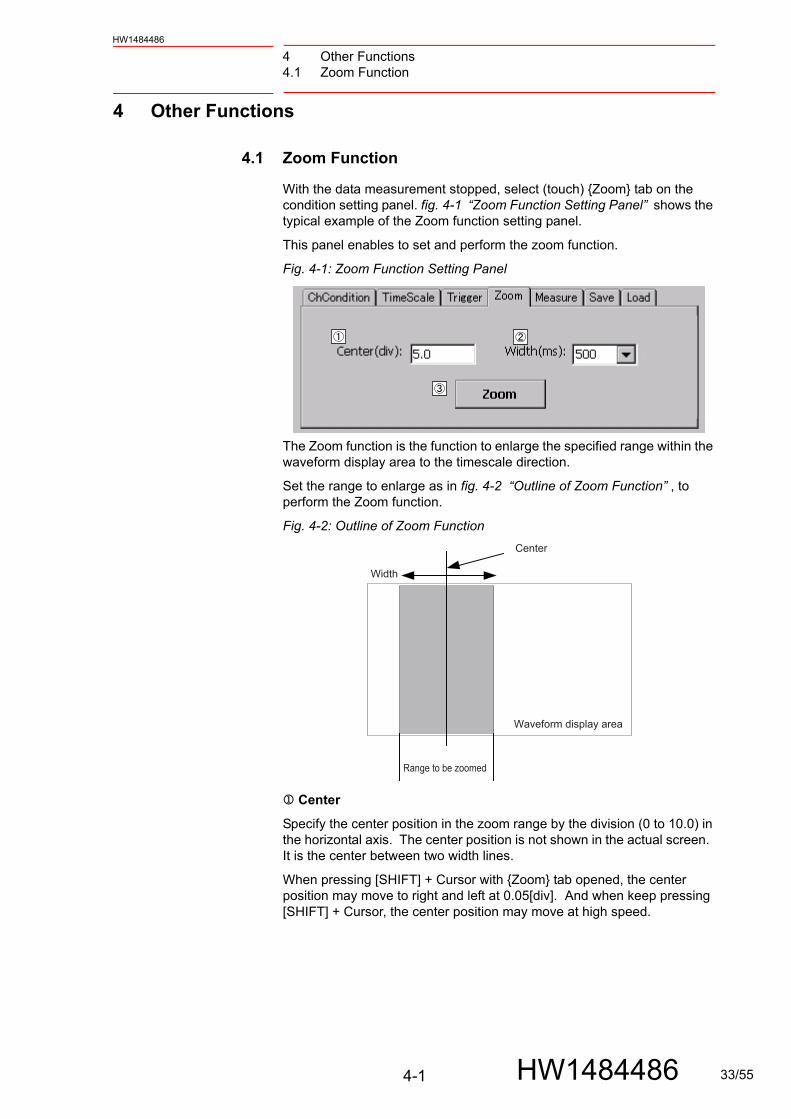
With the data measurement stopped, select (touch) {Zoom} tab on the condition setting panel. fig. 4-1 “Zoom Function Setting Panel” shows the typical example of the Zoom function setting panel.
This panel enables to set and perform the zoom function.
Fig. 4-1: Zoom Function Setting Panel
The Zoom function is the function to enlarge the specified range within the waveform display area to the timescale direction.
Set the range to enlarge as in fig. 4-2 “Outline of Zoom Function” , to perform the Zoom function.
Fig. 4-2: Outline of Zoom Function
Center
Specify the center position in the zoom range by the division (0 to 10.0) in the horizontal axis. The center position is not shown in the actual screen. It is the center between two width lines.
When pressing [SHIFT] + Cursor with {Zoom} tab opened, the center position may move to right and left at 0.05[div]. And when keep pressing [SHIFT] + Cursor, the center position may move at high speed.
Width
Center
Waveform display area
Range to be zoomed
4-1 HW1484486 33/55

4 Other Functions4.1 Zoom Function
HW1484486
Width
Specify the size of zoom range by width, with the center position specified in the Center. The width is shown in the waveform display area by a white line.
In case the width of the range to be zoomed extended outside the waveform display area, the center position is automatically adjusted so that the width fits inside the range.
{Zoom}
Touching this button after setting of Center and Width zooms the specified range.
4.1.1 During Execution of Zoom Function
When the Zoom function is performed, the currently displayed waveform disappears, and the data in the zoom range is enlarged and displayed on the waveform display area. Although the waveform before zoomed temporarily disappears, it is retained inside the system; once canceling the zoom function returns to the original state.
While the zoom function is performed, {Zoom} is switched to {ZoomCancel}.
NOTEWhile the zoom function is performed, operations of {START} and {CH}, and of the panels as tab switch setting become unavailable. To enable these operations, touch {ZoomCancel}.
4-2 HW1484486 34/55

4 Other Functions4.2 Cursor Measurement Function
HW1484486
4.2 Cursor Measurement Function
With the data measurement stopped, select (touch) {Measure} tab on the condition setting panel. fig. 4-3 “Measure Panel and Cursor Display (with Vertical Cursor)” shows the typical example of the Measure panel.
Fig. 4-3: Measure Panel and Cursor Display (with Vertical Cursor)
The cursor measurement function is the function to read the data within the range selected by two cursors, calculate the values corresponding to the specified measurement parameters, and display the result.
CursorType
Select the cursor type either from Horizontal or Vertical. Select the type according to the usage. The {OFF} option makes the function unavailable.
CH
Specify the channel to which the cursor measurement is targeted. The channel specified as unavailable in the Channel Setting window cannot be selected.
Cursor1, Cursor2
When the vertical cursor is selected in , specify the cursor position in the horizontal division (0 to 10.0).
When the horizontal cursor is selected in , specify it in the vertical division (-5.0 to 5.0).
The area enclosed by Cursor1 and Cursor2 becomes the target area of cursor measurement. Even when the positions of Cursor1 and Cursor2 are switched, the target area is always the area inside these two lines.
The cursor is displayed by a white broken line on the waveform display area. When there is no target channel data within the specified cursor range, a part of the measurement parameters is not calculated. When this happens, the result is shown in hyphens (“-”).
Cursor
Measurementparameters
4
4-3 HW1484486 35/55

4 Other Functions4.2 Cursor Measurement Function
HW1484486
CursorMode
When pressing [SHIFT] + Cursor with {Zoom} tab opened, the center position may move 0.05[div] to right and left. And when keep pressing [SHIFT] + Cursor, the position may move at high speed.
When Horizontal cursor type is selected at on the display, the cursor moves horizontally, and it moves vertically when Vertical cursor type is selected.
Only the cursor 1 moves along the key input when “Cursor 1” is selected and only cursor 2 moves when “Cursor 2” is selected. Also, both cursor 1 and 2 moves when “1 and 2” is selected.
4-4 HW1484486 36/55

4 Other Functions4.2 Cursor Measurement Function
HW1484486
4.2.1 Cursor Measurement Parameters
○For horizontal cursor
With the cursor measurement valid, the measurement parameters and the calculation result are automatically displayed at the upper left of waveform display area. The type of measurement parameters in the horizontal cursor is shown in table 4-1 “Measurement Parameters of Horizontal Cursors” .
○For vertical cursor
With the cursor measurement valid, the measurement parameters and the calculation result are automatically displayed at the upper left of waveform display area. The type of measurement parameters in the vertical cursor is shown in table 4-2 “Measurement Parameters of Vertical Cursors” .
Table 4-1: Measurement Parameters of Horizontal Cursors
Parameter Description
Cursor1 Value of measurement target channel at the Cursor1
Cursor2 Value of measurement target channel at the Cursor2
MAX Maximum value of measurement target channel between Cursor1 and Cursor2
MIN Minimum value of measurement target channel between Cursor1 and Cursor2
P-P (Peak to Peak: difference of MAX and MIN)Absolute value of the result obtained by: MAX-MIN
Table 4-2: Measurement Parameters of Vertical Cursors
Parameter Description
Time Time width between Cursor1 and Cursor2
Cursor1 Value of measurement target channel at the Cursor1
Cursor2 Value of measurement target channel at the Cursor2
MAX Maximum value of measurement target channel between Cursor1 and Cursor2
MIN Minimum value of measurement target channel between Cursor1 and Cursor2
P-P (Peak to Peak: difference of MAX and MIN)Absolute value of the result obtained by: MAX-MIN
RMS (RMS: Root Mean Square)Data between Cursor1 and Cursor2; calculated actual value of the measurement target channel
4-5 HW1484486 37/55

4 Other Functions4.3 Job Step No. Saving Function
HW1484486
4.3 Job Step No. Saving Function
When “1” is set to S2C1242, the job step No. saving function is enabled.
In this function, the job name and the step No. which are under execution at the time are added to the waveform data of the CSV file, and the waveform data and the job step No. are related and saved.
Fig. 4-4: Example for Adding Items to Be Saved in CSV File (Job Name and Step No.)
The job name and the step No. are saved only when the play mode executes a job and when the teach mode executes a trial run or a NEXT operation. In a JOG operation or an IO jog operation, the job name and the step No. are not saved.
Table 4-3: Conditions that Job Name and Step No. Are Saved
Operation Saved/not
Playback Saved
Trial run Saved
Interlock + NEXT Saved
NEXT Saved
NEXT for P variable Not
IO jog Not
Jog operation Not
NOTE
The job name and the step No. are assigned to the position instruction. On the other hand, the waveform data interprets the position instruction and acquires data when the motor operates actually. Therefore, deviations of acquisition timing for a certain time occurs between both data.
Be careful when referring to the data which is close to the switching point of the step No.
4-6 HW1484486 38/55

4 Other Functions4.3 Job Step No. Saving Function
HW1484486
4.3.1 Channel Setting
Only one control group can be specified at one measurement time as the control group which is targeted to acquire the job name and the step No.
The setting can be performed in Channel Setting screen of the PP oscilloscope (fig. 4-5 “Adding Items to “ControlGroup” of Channel Setting Screen” ). When the job including a control group which is set in this item works, the job name and the step No. are saved.
Fig. 4-5: Adding Items to “ControlGroup” of Channel Setting Screen
4.3.2 Adjustment of Acquisition Time of Job Name and Step No.
When the job cursor reaches END or when the other job is called (when the assignment of the job name and the step No. to the targeted control group are stopped), the job name and the step No. which are output lastly can be kept recording for a certain time.
This can be performed when assignment of the job name and the step No. are interrupted because of the deviation of the waveform against the instruction.
S4C1039 can adjust this addition time (unit: msec, default value: 500 msec).
4-7 HW1484486 39/55

4 Other Functions4.3 Job Step No. Saving Function
HW1484486
Fig. 4-6: Example for Acquisition Time of Job Name and Step No.
CH1, Signal for indicating "under running"
CH2, Speed FB CH3, Torque instruction
Additional time for acquiring job names and step Nos.
Range that job names and step Nos. are generally added
4-8 HW1484486 40/55

4 Other Functions4.4 Operation Function by Dedicated Input
HW1484486
4.4 Operation Function by Dedicated Input
When “1” is set to S2C1244, the signal operation function is enabled. This function makes the following operations performed on the programming pendant executable externally by the dedicated input signals.
• Starting PP oscilloscope
• Starting measurement
• Saving CSV file
Also, the PP oscilloscope status is output to the dedicated output signal, and it can be externally referred.
4.4.1 Dedicated Input Signal
40760: Starting Pendant OscilloscopeStarts PP oscilloscope. When PP oscilloscope is in minimized status, it is released.
This signal performs the same operation as the operation when pressing {Robot} → {Pendant oscilloscope} from the main menu.
NOTE
This function aims to start measurement externally without operating and referring to the programming pendant. Therefore, it has no dedicated input signal to stopmeasurement.
For stopping measurement, use the trigger mode.
40767 40766 40765 40764 40763 40762 40761 40760
SIN#608 SIN#607 SIN#606 SIN#605 SIN#604 SIN#603 SIN#602 SIN#601
OSCSAVE START
OSCMEAS.START
OSC STARTUP
NOTE
When it is in one of the following status, pendant oscillo-scope cannot be started even if this signal is turned ON. After releasing the status, turn ON this signal.
• An error exists.
• Other external application is running.
Rising
4-9 HW1484486 41/55

4 Other Functions4.4 Operation Function by Dedicated Input
HW1484486
40761: Pendant Oscilloscope Starting MeasurementStarts measurement.
This signal performs the same operation as the operation when pressing [START] of PP oscilloscope.
40762: Pendant Oscilloscope Saving CSV File Saves the measured data to the CSV file.
This signal performs the same operation as the operation when pressing [Save CSV] of PP oscilloscope.
Rising
NOTE
The measurement start requesting signal (40761) and the CSV file saving requesting signal (40762) are monitored only when the signal acceptance ready (51172) is ON.
In order to accept the request surely, put a requesting signal with the following procedure.
• After the signal acceptance ready (51172) is turned ON, wait for 1 second, and then put the signal.
• After putting the signal, ON status should be maintained for 1 second or longer.
Rising
1 sec. or longer
1 sec. or longer
Signal acceptance ready(51172)
Measurement start request(40761)
4-10 HW1484486 42/55

4 Other Functions4.4 Operation Function by Dedicated Input
HW1484486
4.4.2 Dedicated Output Signal
Displays PP oscilloscope operation status. When PP oscilloscope is not running, all signals are OFF.
50903: Pendant Oscilloscope Under MeasurementNotifies that measurement is currently performed.
Only this signal varies regardless of S2C1244 setting.
51170: Pendant Oscilloscope RunningNotifies that PP oscilloscope is running.
This signal is turned ON even if PP oscilloscope is in minimized status.
51171: Pendant Oscilloscope MinimizedNotifies that PP oscilloscope is in minimized status.
50907 50906 50905 50904 50903 50902 50901 50900
SOUT#720 SOUT#719 SOUT#718 SOUT#717 SOUT#716 SOUT#715 SOUT#714 SOUT#713
MEASURING PP-OSC
51177 51176 51175 51174 51173 51172 51171 51170
SOUT#936 SOUT#935 SOUT#934 SOUT#933 SOUT#932 SOUT#931 SOUT#930 SOUT#929
OSC SAVE ERROR
OSC SAVING
OSC MEAS.ERROR
OSC I/O READY
OSC MINIMIZE
OSC RUNNING
State
State
SUPPLE-MENT
PP oscilloscope is minimized by the following factors:
• The {MINIMIZE} is pressed.
• An alarm or an error occurs.
The minimized status can be canceled by selecting {Pendant oscilloscope} from the main menu or using the start request-ing signal (40760).
State
4-11 HW1484486 43/55

4 Other Functions4.4 Operation Function by Dedicated Input
HW1484486
51172: Pendant Oscilloscope IO Acceptance ReadyNotifies that PP oscilloscope is monitoring the start request (40761) and the CSV file saving request (40762).
51173: Pendant Oscilloscope Measurement ErrorNotifies that the measurement failed to start when {START} or the start requesting signal (40761) tried to start measurement. Check that there are no errors in the measurement conditions.
This signal is turned OFF when newly starting measurement.
51174: Pendant Oscilloscope CSV File Under SavingNotifies that the CSV file is under saving.
51175: Pendant Oscilloscope CSV File Error in SavingNotifies that saving is failed when starting saving with {Save CSV} or the CSV file saving requesting signal (40762). Check the condition of the external storage device.
This signal is turned OFF when newly starting saving.
When requesting saving in the condition that the measurement is never performed after starting PP oscilloscope, saving is not performed but this signal is not turned ON.
SUPPLE-MENT
Only when the following conditions are satisfied, this signal is turned ON.
• Measurement CH settings are completed.
• Not under measurement.
• Not under saving the CSV file.
• Not in the minimized status.
• Not under zooming (Section 4.1.1).
State
State
State
State
4-12 HW1484486 44/55

4 Other Functions4.5 Simultaneous Display of Waveform Display Area and Reading Job
HW1484486
4.5 Simultaneous Display of Waveform Display Area and
Reading Job
After measuring the waveform, the waveform display area and the measured job (reading job) can be displayed simultaneously to check the relation with the waveform and the measured job.
When using this function, set the job step No. saving function described in chapter 4.3 “Job Step No. Saving Function” to be enabled.
A reading job is only for reading. This job cannot be edited.
4.5.1 Displaying Method
1. Set the parameter S2C1242 to 1, and set the job step No. saving function to be enabled.
2. Select {ROBOT} from the menu in the left of screen.
3. Select {PENDANT OSCILLOSCOPE} from the expanded menu.
4. Specify the control group according to chapter 4.3.1 “Channel Setting” .
5. Press {START} to start the measurement.
6. When the targeted data waveform is displayed in the waveform display area, press {STOP} to stop the measurement. {MULTI} is activated.
Fig. 4-7: {MULTI}
4-13 HW1484486 45/55

4 Other Functions4.5 Simultaneous Display of Waveform Display Area and Reading Job
HW1484486
7. Press {MULTI}. The reading job and the waveform display area are displayed simultaneously.
Fig. 4-8: Reading Job and Waveform Display Area
8. Selecting {ROBOT} - {PENDANT OSCILLOSCOPE} again clears the waveform data.
4-14 HW1484486 46/55

4 Other Functions4.5 Simultaneous Display of Waveform Display Area and Reading Job
HW1484486
4.5.2 Display Items
Fig. 4-9: Reading Job and Waveform Display Area
Each item on the screen means as follows:
JOB
Displays a job name of the measured data.
STEP
Displays a step number of the measured data.
Cursor
Indicates the data when the step number of the job name displayed at and is executed.
Condition setting panel
Enables to set various conditions. Touching the upper tab enables to open the setting window corresponding to each item.
READING JOB
A job only for reading. The cursor positions of and the cursor position of the job indicate the same position.
{EDIT JOB}
Pressing this button switches from the reading job to the ordinary job which can be edited.
The both cursor positions, the waveform and the job, indicate the same position.
4-15 HW1484486 47/55

4 Other Functions4.5 Simultaneous Display of Waveform Display Area and Reading Job
HW1484486
4.5.3 Operating Methods
1. After finishing displaying the waveform, press {MULTI}.
2. Select a tab of the condition setting panel {Info} or {Save}.
3. Press [SHIFT] + Cursor to move the cursor on the waveform display area and the cursor on the job together in step units. The relation with the waveform and the job can be checked. With {Zoom} tab open, press [SHIFT] + Cursor, the center position may move to right or left.
Fig. 4-10: Interlocked Movement Between Cursor on Waveform Display Area and Cursor on Reading Job
4. When editing the job with checking the waveform, press {EDIT JOB}. A reading job is only for reading. This job cannot be edited. Pressing {EDIT JOB} switches from the reading job to the ordinary job, and the job can be edited. When pressing {EDIT JOB}, a dialog which indicates the operation cannot be restarted is displayed.
NOTICE
When a job is switched from the reading job to the ordinary job by pressing [EDIT JOB], the cursor position of the job moves to the cursor position specified by the reading job. Therefore, after the subsequent restart, the robot cannot resume its operation. When performing the restart, check the robot position and the cursor position, and then execute the restarting operation.
4-16 HW1484486 48/55

4 Other Functions4.5 Simultaneous Display of Waveform Display Area and Reading Job
HW1484486
Fig. 4-11: Dialog to Indicate Operation Cannot Be Restarted
5. Selecting {YES} switches to the ordinary job.
Fig. 4-12: Ordinary Job and Waveform Display Area
6. The job is enabled to be edited. When performing edit other than adding a move instruction, pressing {VIEW JOB} can display READING JOB again. When adding a move instruction, READING JOB cannot be displayed again.
4-17 HW1484486 49/55

4 Other Functions4.5 Simultaneous Display of Waveform Display Area and Reading Job
HW1484486
4.5.4 When in 3D Graphical Display Function
When the 3D graphical display function, which is an optional function, is valid, the waveform display area and the robot's 3D model can be displayed simultaneously to check the relation between the waveform and the robot position.
1. After finishing displaying the waveform, press {MULTI}.
Fig. 4-13: When 3D Graphic Display is Valid
2. Press {3D-ROBOT} to display the 3D model.
Fig. 4-14: 3D-ROBOT and Waveform Display Area
3. Select a tab of the condition setting panel {Info} or {Save}.
4. Press [SHIFT] + Cursor to operate the cursor on the waveform display area and the 3D robot together in step units. The relation between the waveform and the robot position can be checked. The 3D robot operates at the teaching position of the step.
4-18 HW1484486 50/55
5 Supplementary Explanation5.1 Division [div]: Unit for Measurement Screen Position
HW1484486
5 Supplementary Explanation
Here explains some of the terms used in this manual.
5.1 Division [div]: Unit for Measurement Screen Position
The PP oscilloscope includes the operation that specifies the various positions (or range) in the waveform display area, such as specifying zero point of measurement channel, specifying cursor range, or zoom range.
To specify these positions, unit of “division [div]” is used. Here describes the details.
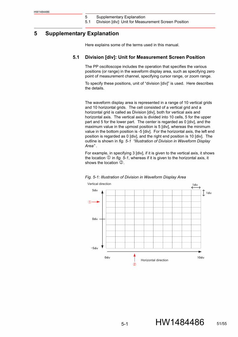
The waveform display area is represented in a range of 10 vertical grids and 10 horizontal grids. The cell consisted of a vertical grid and a horizontal grid is called as Division [div], both for vertical axis and horizontal axis. The vertical axis is divided into 10 cells, 5 for the upper part and 5 for the lower part. The center is regarded as 0 [div], and the maximum value in the upmost position is 5 [div], whereas the minimum value in the bottom position is -5 [div]. For the horizontal axis, the left end position is regarded as 0 [div], and the right end position is 10 [div]. The outline is shown in fig. 5-1 “Illustration of Division in Waveform Display Area” .
For example, in specifying 3 [div], if it is given to the vertical axis, it shows the location in fig. 5-1, whereas if it is given to the horizontal axis, it shows the location .
Fig. 5-1: Illustration of Division in Waveform Display Area
Vertical direction
Horizontal direction
5-1 HW1484486 51/55

5 Supplementary Explanation5.2 Reference Unit
HW1484486
5.2 Reference Unit
Here describes the reference unit.
The data of measurement target has each unit, as shown in table 5-1 “Unit of Data” .
When the speed reference is selected as a measurement signal of the target channel, the initial value of the reference unit is 1000 [rpm/div]. This means that the speed is 1000 [rpm] when the output of vertical 1 [div] is given from the target channel zero position. From this relationship, the outline of waveform data output on the waveform display area can be grasped.
Example: with the setting of 1000 [rpm/div]:
Output of 2.0 [div]: 2000 [rpm]
Output of -3.3 [div]: -3300 [rpm]
Since the reference unit can be changed in {ChCondition} tab, the waveform display scale in the vertical direction can be changed accordingly.
Example: with the actual output of 1000 [rpm]:
Setting of 1000 [rpm/div]: Output of 1 division
Setting of 500 [rpm/div]: Output of 2 divisions
Table 5-1: Unit of Data
Data type Unit
Speed reference
[rpm]Rotating speed of target axis motor in a minute
Speed feedback
[rpm]Actual rotating speed of target axis motor in one minute
Torque reference
[%]Current torque reference value when the target axis motor rated torque is converted as 100%.
Encoder temperature
[°C]Current temperature of target measurement axis encoder
Concurrent I/O No unit, for it is just an ON/OFF signal.To differentiate from other signal data, [U] (unit) is used for expediency.OFF: 0 U is outputON: 1.0 U is output
Register No unit, for it is just an register value.Register value is output without changed.Example: When the vertical scale is 100[-/div] and the target register value is 200, the output of 2 divisions is given.
NOTEThis temperature sensor is to detect an encoder error. There might be a little difference between the actual tem-perature and the encoder temperature which is output by this function.
5-2 HW1484486 52/55

6 Error MessagesHW1484486
6 Error Messages
The pendant oscilloscope can output the messages for confirming the operation or notifying the process completion. Especially when the data acquisition error or abnormal setting should occur, the application outputs error messages such as shown in fig. 6-1 “Example of Error Message” to notify the problem.
When any error message is displayed, first check the content, touch {OK} to clear the message, and follow necessary countermeasures.
Fig. 6-1: Example of Error Message
table 6-1 “Error Messages and Countermeasures of PP Oscilloscope” shows the list of error messages and the countermeasure.
Table 6-1: Error Messages and Countermeasures of PP Oscilloscope (Sheet 1 of 2)
Error messages Countermeasures
Input the value between ** and **.The value to ** decimal places can be input.Input the numeric value.(**: numerical value)
The input value is out of the limitation of input box. Retry inputting a correct value according to the error message. This error can occur in all of the input boxes.
The specified number for the alarm trigger is not correct.Review the setting.
A non-existent number is specified as the alarm number of alarm trigger. Retry setting a correct number.
Any trigger can be detected with this setting.Review the trigger level setting.
The trigger level is out of the waveform display area due to excessively large trigger level or channels zero position.Check the trigger level setting.
The axis number which doesn't exist in the system has been specified.Review the channel setting.
The axis number which does not exist in the system is specified to either of axes in the channel setting window. Set the correct number.
Input correct I/O number. The concurrent I/O number which does not exist is specified. Set the correct number.
Processing time insufficient.Set slower sampling time or decrease the number of available channels.
Process time for data acquisition is not enough for the volume of measurement data. Set a slower sampling time, or decrease the available channel number.
6-1 HW1484486 53/55

6 Error Messages
HW1484486
The acceptable delaying range of graph drawing exceeded. Implement any of the following countermeasures.- Set slower sampling time.- Decrease the number of available channels.- Set shorter value for Time Scale setting. (Shorten the data length.)
Process time for graph drawing is not enough for the volume of measurement data. Set a slower sampling time, decrease the available channel number, or set shorter timescale value.
No corresponding data exists within the zoom range.
There is no measurement data within the zoom range currently specified. Set the zoom range again.
Cannot recognize Flash Memory.Setting for SaveMode is switched from Auto to Manual.
Insert SD or USB memory and set SaveMode again.
Cannot recognize Flash Memory.SaveMode is switched from Auto to Manual.Perform manual saving if necessary.
Flash memory could not be recognized at data save. Insert SD or USB memory and retry data saving manually.
Failed in saving CSV file. Perform manual saving if necessary.
An error has occurred in flash memory.Try SD or USB memory insertion again or replacement, and retry data saving manually.
Not enough disk space.Make room for the file to perform manual saving.
Assure enough disk space for SD or USB memory.
File format is not correct. The file to load has not been matched with the data format of PP oscilloscope. Check if the file has been correctly saved.
Failed in loading CSV file. The file to load has been found not to be the correct file for the PP oscilloscope. The file cannot be loaded.
File not specified. Specify the file to load.
Specified file not exist. The specified file does not exist on the SD or USB memory.
Failed in starting measurement. An error has occurred at measurement start, and the measurement cannot be started. Retry the measurement. If the alarm persists, terminate the pendant oscilloscope application, and restart the application.
Failed in obtaining measured value.[**]Measurement is canceled.(**: numerical value)
An error was found in the acquired measurement data. The system is forcefully turned into the measurement stop condition. Retry the measurement. If the alarm persists, terminate the pendant oscilloscope application, and restart the application.
Failed in completing measurement. The measurement process has not been correctly completed. Terminate the pendant oscilloscope application, and restart the application.
Table 6-1: Error Messages and Countermeasures of PP Oscilloscope (Sheet 2 of 2)
Error messages Countermeasures
6-2 HW1484486 54/55

YRC1000micro OPTIONSINSTRUCTIONSFOR PENDANT OSCILLOSCOPE FUNCTION
C 2017 YASKAWA ELECTRIC CORPORATIONPublished by YASKAWA
MANUAL NO.
1
February 2020 17-07
HW1484486 55/55