you just got the geotech report. now what?
TRANSCRIPT

Caro
lloB
lueT
em
pla
teW
ithLogo.p
ptx
You Just Got the Geotech Report.
Now What?
PNWS-AWWA
Water Infrastructure Seismic Design Considerations
Brian Casey, P.E.
Carollo Engineers, Inc.
Caro
lloB
lueT
em
pla
teW
ithLogo.p
ptx
2
Four key steps guide the implementation
of geotechnical seismic considerations
1. Review and dissect the report
2. Communicate information, options, and
implications
3. Determine design criteria
4. Incorporate approach into design

Caro
lloB
lueT
em
pla
teW
ithLogo.p
ptx
3
REVIEW AND DISSECT

Caro
lloB
lueT
em
pla
teW
ithLogo.p
ptx
4
Seismic considerations include three key
items:
• Liquefaction
– Potential for liquefying and consolidation of soils
• Seismic movement
– Shaking motion during a quake
• Ground displacement
– Location of ground features following a quake

Caro
lloB
lueT
em
pla
teW
ithLogo.p
ptx
5
Dissection of the geotech report is critical
to identifying key seismic design influences
Site
conditions
Seismic
Considerations
Design Values Hazards
Caro
lloB
lueT
em
pla
teW
ithLogo.p
ptx
6
The geotech report contains essential
information for proper facility design
• Seismic demand (lateral and vertical accelerations)
– Soil type
– Site specific analysis
• Foundation system (deep, mat, shallow)
• Slope stability and excavation protection
recommendations
• Anticipated settlement (piping flexibility
requirements)
• Wall and foundation sizing
– Lateral pressure based on soil type and acceleration

Caro
lloB
lueT
em
pla
teW
ithLogo.p
ptx
7
COMMUNICATE INFORMATION

Caro
lloB
lueT
em
pla
teW
ithLogo.p
ptx
8
Communication of geotech considerations
is critical to decision-making
• Project owner – cost implications
• Design team
– Structural
– Civil – site layout
– Electrical – conduit runs
– Mechanical – equipment anchorage

Caro
lloB
lueT
em
pla
teW
ithLogo.p
ptx
9
Communication of geotech considerations
is critical to decision-making
Ground displacement
Liquefaction
Sloshing
Anchorage

Caro
lloB
lueT
em
pla
teW
ithLogo.p
ptx
10
Sloshing develops significant forces that
can result in tank failures
sismo7.2mexicalialberca4-abril-2010.wmv

Caro
lloB
lueT
em
pla
teW
ithLogo.p
ptx
11
Sloshing can lead to various types of
tank wall failure
Courtesy of the National Information Service for Earthquake
Engineering, EERC, University of California, Berkeley
Haiti 2010
San Fernando 1971
Long Beach 1933
Caro
lloB
lueT
em
pla
teW
ithLogo.p
ptx
12
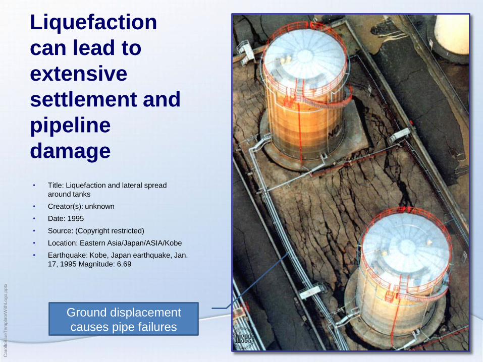
Liquefaction
can lead to
extensive
settlement and
pipeline
damage
• Title: Liquefaction and lateral spread
around tanks
• Creator(s): unknown
• Date: 1995
• Source: (Copyright restricted)
• Location: Eastern Asia/Japan/ASIA/Kobe
• Earthquake: Kobe, Japan earthquake, Jan.
17, 1995 Magnitude: 6.69
Ground displacement
causes pipe failures

Caro
lloB
lueT
em
pla
teW
ithLogo.p
ptx
13
Liquefaction can also lead to structures
floating upward
• Title: Manhole raised by liquefaction
• Creator(s): Bardet, Jean-Pierre
• Date: 2004-10-31
• Location: Eastern Asia/Japan/ASIA
• Earthquake: Niigata-Ken Chuetsu, Japan earthquake, Oct. 23,
2004 Magnitude: 6.8

Caro
lloB
lueT
em
pla
teW
ithLogo.p
ptx
14
DETERMINE CRITERIA
Caro
lloB
lueT
em
pla
teW
ithLogo.p
ptx
15
Final level of design is based on
requirements and policy
• Building/seismic code requirements
• State/local resiliency standards and goals
• ASCE
• American Lifelines Alliance
• Practical system vulnerability
– Existing redundancy within a system
– Historical challenges with system components

Caro
lloB
lueT
em
pla
teW
ithLogo.p
ptx
16
The design team needs to account for the
extent and types of risks identified
• Primary goals:
– Safe environment for operators
– Continued water flow following a quake
– Continued functionality
• Design requirements:
– Foundation stability
– Pipeline flexibility
– Equipment anchorage

Caro
lloB
lueT
em
pla
teW
ithLogo.p
ptx
17
INCORPORATE INTO DESIGN

Caro
lloB
lueT
em
pla
teW
ithLogo.p
ptx
18
Each project component must be
designed to address all seismic concerns
• Liquefaction
– Threat: Infrastructure sinks, floats, or settles differentially
– Solution: Remediate, support and/or anchor
• Seismic movement
– Threat: Sloshing or differential motion
– Solution: Adequate design and connection flexibility
• Ground displacement
– Threat: Differential settlement
– Solution: Proper sizing and flexibility
Caro
lloB
lueT
em
pla
teW
ithLogo.p
ptx
19
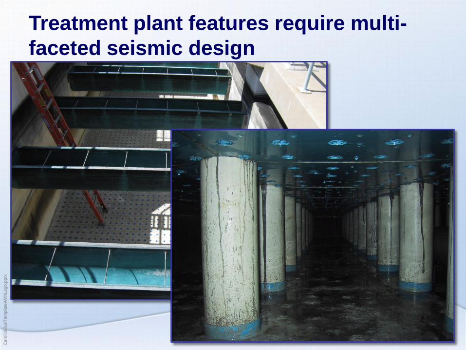
Treatment plant features require multi-
faceted seismic design
Caro
lloB
lueT
em
pla
teW
ithLogo.p
ptx
20
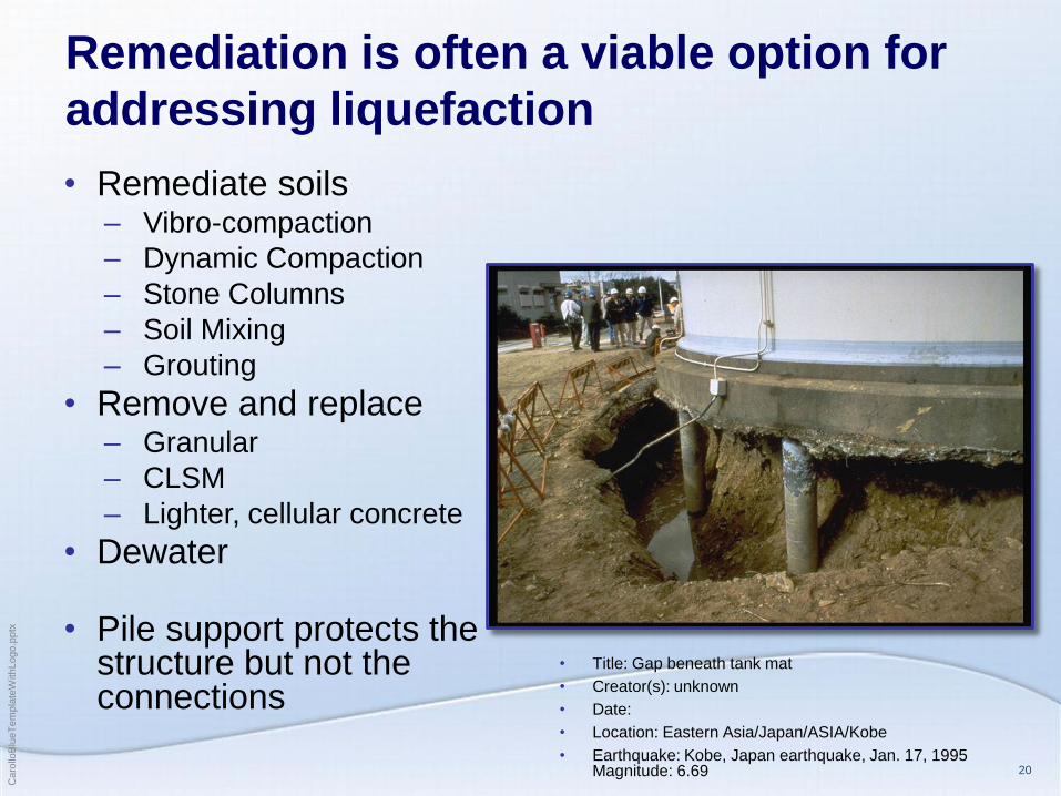
Remediation is often a viable option for
addressing liquefaction
• Remediate soils – Vibro-compaction
– Dynamic Compaction
– Stone Columns
– Soil Mixing
– Grouting
• Remove and replace – Granular
– CLSM
– Lighter, cellular concrete
• Dewater
• Pile support protects the structure but not the connections
• Title: Gap beneath tank mat
• Creator(s): unknown
• Date:
• Location: Eastern Asia/Japan/ASIA/Kobe
• Earthquake: Kobe, Japan earthquake, Jan. 17, 1995 Magnitude: 6.69

Caro
lloB
lueT
em
pla
teW
ithLogo.p
ptx
21
Examples of foundation designs that
address liquefaction include…
• Shallow foundation on
remediated soil
• Mat foundation
– Large/spread,
thickened slab
• Deep foundation
– Piles
Caro
lloB
lueT
em
pla
teW
ithLogo.p
ptx
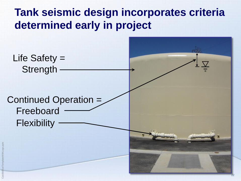
22
Tank seismic design incorporates criteria
determined early in project
Continued Operation =
Freeboard
Life Safety =
Strength
Flexibility

Caro
lloB
lueT
em
pla
teW
ithLogo.p
ptx
23
Accommodating sloshing in a tank
requires additional freeboard
Water Reservoir Freeboard, ft
Aspect Ratio
D/H
Dia.
(ft)
Los
Angeles Bakersfield Portland Seattle
5 150 7’ 12’ 8’ 7’
2 60 6’ 10’ 6’ 5’
0.5 15 3’ 5’ 3’ 2’
Side water Depth: 30 ft
Caro
lloB
lueT
em
pla
teW
ithLogo.p
ptx
24
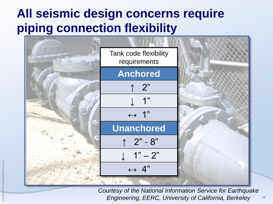
All seismic design concerns require
piping connection flexibility
Courtesy of the National Information Service for Earthquake
Engineering, EERC, University of California, Berkeley
Anchored
↑ 2”
↓ 1”
↔ 1”
Unanchored
↑ 2” - 8”
↓ 1” – 2”
↔ 4”
Tank code flexibility
requirements

Caro
lloB
lueT
em
pla
teW
ithLogo.p
ptx
25
Design of piping flexibility is dictated by
geotech report design values
Seismic isolation
valve
Flat plate support
Flex fitting

Caro
lloB
lueT
em
pla
teW
ithLogo.p
ptx
26
Critical piping flexibility needs to be
accounted for in cost estimates
Caro
lloB
lueT
em
pla
teW
ithLogo.p
ptx
27
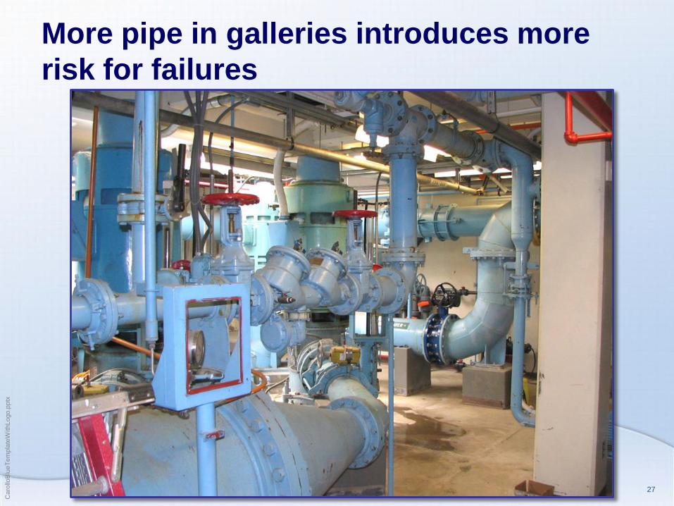
More pipe in galleries introduces more
risk for failures

Caro
lloB
lueT
em
pla
teW
ithLogo.p
ptx
28
Pipe supports that incorporate seismic
design loads require significant space
Caro
lloB
lueT
em
pla
teW
ithLogo.p
ptx
29
In summary, implementation of
geotechnical criteria follows four steps…
1. Review and dissect the report
2. Communicate information, options, and
implications
3. Determine design criteria
4. Incorporate approach into design

Caro
lloB
lueT
em
pla
teW
ithLogo.p
ptx
Questions?
Credits:
Dave Kraska, P.E.
Yousef Nouri, P.E.
Mike Dadik, P.E.