y. p. chugh, h. gurley, b.abbasi, s. bastola, c....
TRANSCRIPT
Analysis and Measurement of Ground
Control Stability in Set-Up Rooms and
Gate Roads in an Illinois Longwall
Operation
Y. P. Chugh, H. Gurley, B.Abbasi,
S. Bastola, C. Carlton
In cooperation with
American Coal Galatia Mine
August 2012
• Engineering and operations professional staff at Galatia Mine for their continuous involvement, review of concepts and results and technical support in field implementation.
• Project team listed here and an unsung hero- John Pulliam - backbone of in-mine instrumentation and data gathering activities.
• Illinois Clean Coal Institute of the Department of Commerce and Economic Opportunity for financial support for this important project.
• NIOSH for providing continuous monitoring equipment.
A Few Major Thanks….
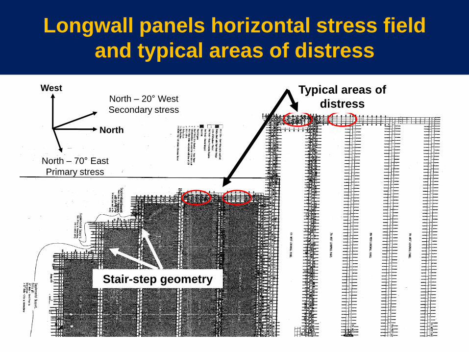
Longwall panels horizontal stress field
and typical areas of distress
West Typical areas of
distress
North
North – 70° East
Primary stress
North – 20° West
Secondary stress
Stair-step geometry
Observations in set-up rooms areas
• Loosening of roof trusses
• Shearing of roof bolts along the head.
• Excessive roof to floor convergence.
• Cutter roof and roof failures
• Water “drippers” from roof
• Crib and supplementary supports
movements
• Floor heave
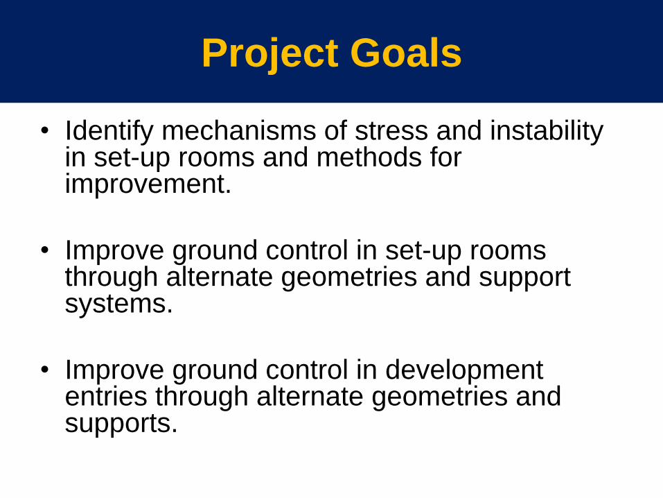
Project Goals
• Identify mechanisms of stress and instability in set-up rooms and methods for improvement.
• Improve ground control in set-up rooms through alternate geometries and support systems.
• Improve ground control in development entries through alternate geometries and supports.
Identify and Test Mechanisms of Instability in Set Up Rooms
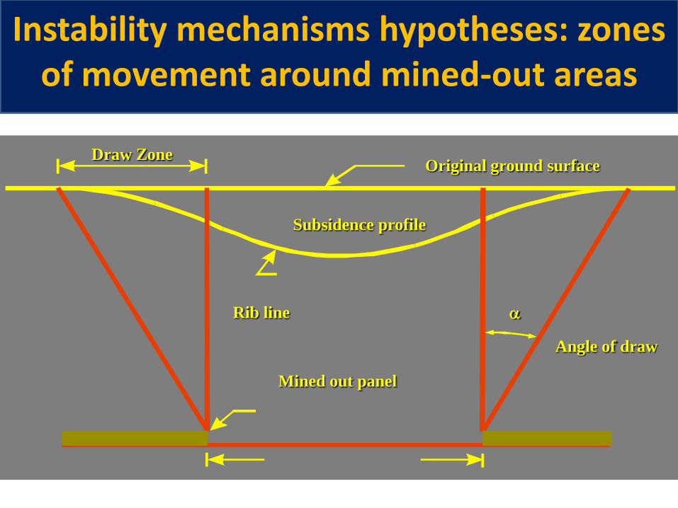
Original ground surface Draw Zone
Subsidence profile
Rib line
Mined out panel
Angle of draw
a
Instability mechanisms hypotheses: zones of movement around mined-out areas
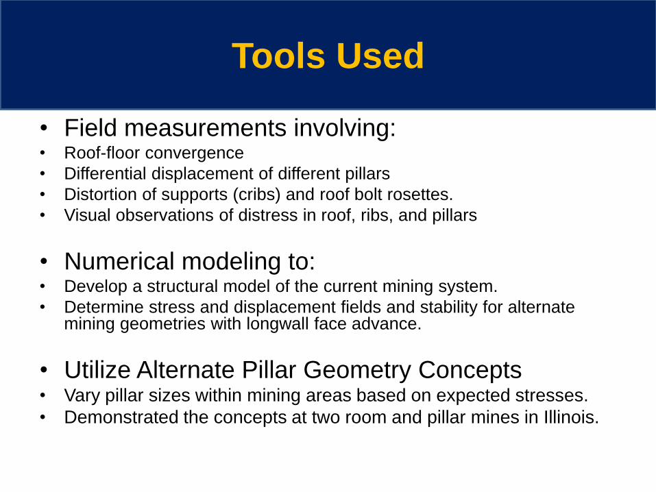
Tools Used
• Field measurements involving: • Roof-floor convergence
• Differential displacement of different pillars
• Distortion of supports (cribs) and roof bolt rosettes.
• Visual observations of distress in roof, ribs, and pillars
• Numerical modeling to: • Develop a structural model of the current mining system.
• Determine stress and displacement fields and stability for alternate mining geometries with longwall face advance.
• Utilize Alternate Pillar Geometry Concepts • Vary pillar sizes within mining areas based on expected stresses.
• Demonstrated the concepts at two room and pillar mines in Illinois.
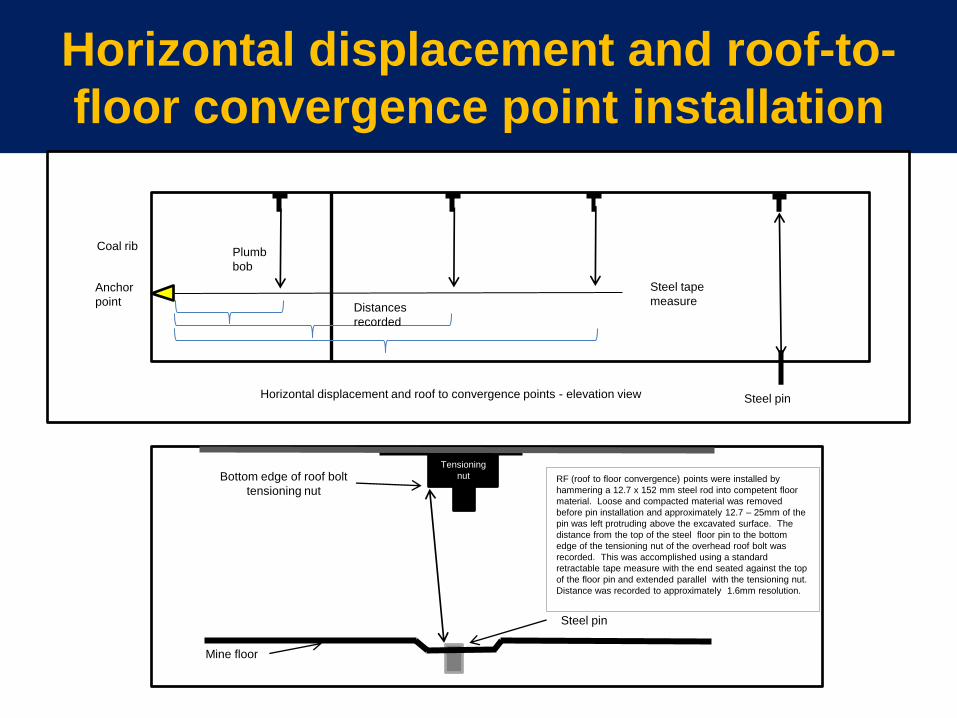
Horizontal displacement and roof-to-
floor convergence point installation
Horizontal displacement and roof to convergence points - elevation view
Anchor
point
Coal rib Plumb
bob
Steel tape
measure Distances
recorded
Steel pin
Tensioning
nut RF (roof to floor convergence) points were installed by
hammering a 12.7 x 152 mm steel rod into competent floor
material. Loose and compacted material was removed
before pin installation and approximately 12.7 – 25mm of the
pin was left protruding above the excavated surface. The
distance from the top of the steel floor pin to the bottom
edge of the tensioning nut of the overhead roof bolt was
recorded. This was accomplished using a standard
retractable tape measure with the end seated against the top
of the floor pin and extended parallel with the tensioning nut.
Distance was recorded to approximately 1.6mm resolution.
Bottom edge of roof bolt
tensioning nut
Mine floor
Steel pin
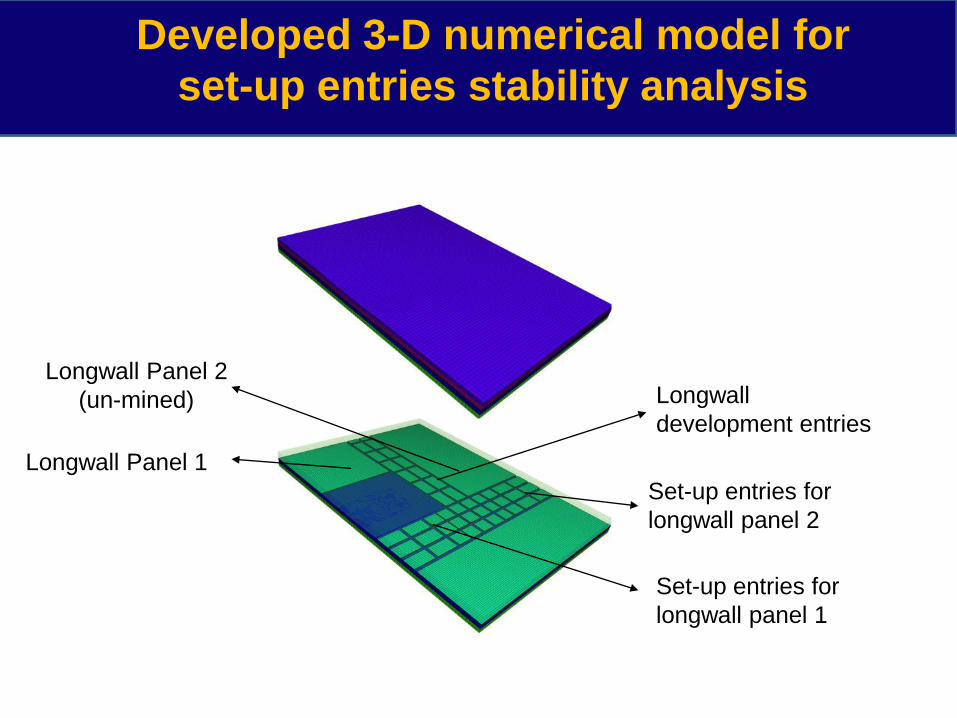
Longwall Panel 2
(un-mined)
Set-up entries for
longwall panel 1
Longwall Panel 1
Longwall
development entries
Set-up entries for
longwall panel 2
Developed 3-D numerical model for
set-up entries stability analysis
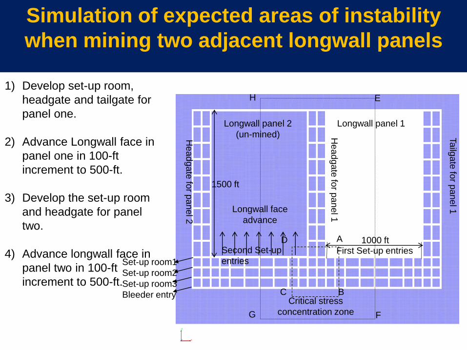
Simulation of expected areas of instability
when mining two adjacent longwall panels
Ta
ilga
te fo
r pa
ne
l 1
He
ad
ga
te fo
r pa
ne
l 1
Longwall panel 1 Longwall panel 2
(un-mined)
Longwall face
advance
He
ad
ga
te fo
r pa
ne
l 2
Critical stress
concentration zone
First Set-up entries 1000 ft
1500 ft
Set-up room1
Set-up room2
Set-up room3
Bleeder entry
Second Set-up
entries
A
B C
D
E
F G
H
1) Develop set-up room,
headgate and tailgate for
panel one.
2) Advance Longwall face in
panel one in 100-ft
increment to 500-ft.
3) Develop the set-up room
and headgate for panel
two.
4) Advance longwall face in
panel two in 100-ft
increment to 500-ft.
0
0.2
0.4
0.6
0.8
1
1.2
0 20 40 60 80 100 120 140
VS
CF
Distance (ft)
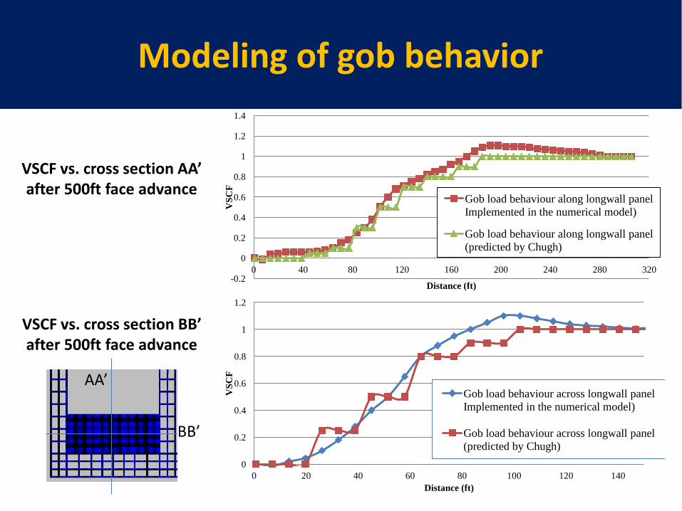
Gob load behaviour across longwall panel
Implemented in the numerical model)
Gob load behaviour across longwall panel
(predicted by Chugh)
-0.2
0
0.2
0.4
0.6
0.8
1
1.2
1.4
0 40 80 120 160 200 240 280 320
VS
CF
Distance (ft)
Gob load behaviour along longwall panel
Implemented in the numerical model)
Gob load behaviour along longwall panel
(predicted by Chugh)
VSCF vs. cross section AA’ after 500ft face advance
VSCF vs. cross section BB’ after 500ft face advance
AA’
BB’
Modeling of gob behavior
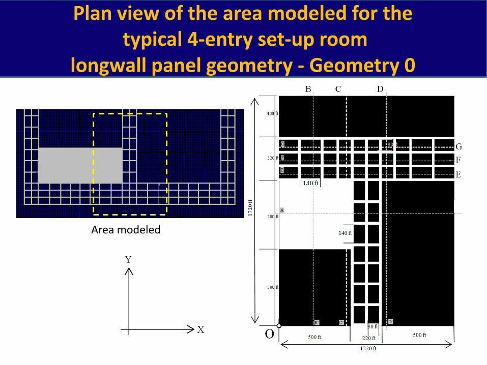
Plan view of the area modeled for the typical 4-entry set-up room
longwall panel geometry - Geometry 0
Area modeled
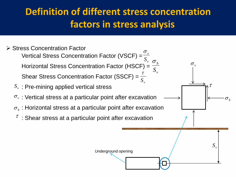
Definition of different stress concentration factors in stress analysis
Stress Concentration Factor
v
v
S
v
h
S
vS
vS
v
h
Vertical Stress Concentration Factor (VSCF) =
Horizontal Stress Concentration Factor (HSCF) =
Shear Stress Concentration Factor (SSCF) =
: Pre-mining applied vertical stress
: Vertical stress at a particular point after excavation
: Horizontal stress at a particular point after excavation
: Shear stress at a particular point after excavation
v
h
vSUnderground opening
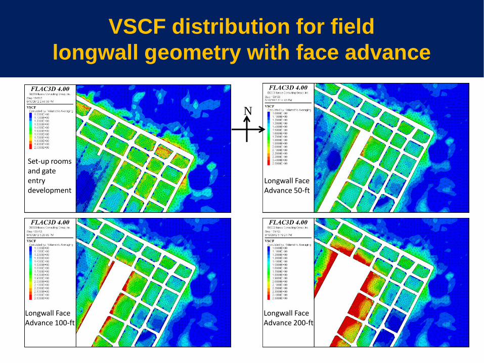
VSCF distribution for field
longwall geometry with face advance
Longwall Face Advance 50-ft
N
Longwall Face Advance 200-ft
Longwall Face Advance 100-ft
Set-up rooms and gate entry development
Vertical stress= 2.2 MPa Vertical stress = 2.5 MPa
3.3
2.75
2.2
1.65
1.1
0.55
0
0.7 1.4 2.1 2.8 3.5 4.2 4.9
3.3
2.75
2.2
1.65
1.1
0.55
0
0.7 1.4 2.1 2.8 3.5 4.2 4.9
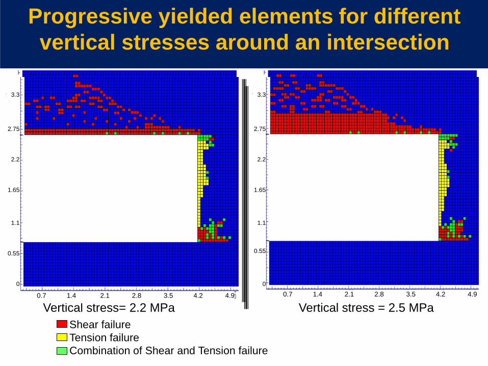
Shear failure
Tension failure
Combination of Shear and Tension failure
Progressive yielded elements for different
vertical stresses around an intersection
3.3
2.75
2.2
1.65
1.1
0.55
0
0.7 1.4 2.1 2.8 3.5 4.2 4.9
3.3
2.75
2.2
1.65
1.1
0.55
0
0.7 1.4 2.1 2.8 3.5 4.2 4.9
Studies at Mine 1
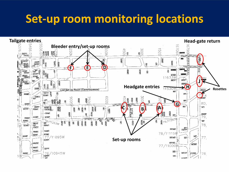
Set-up room monitoring locations
I
J
Bleeder entry/set-up rooms
Set-up rooms
Headgate entries
Tailgate entries
A C B G
H
D E F
Rosettes
Head-gate return
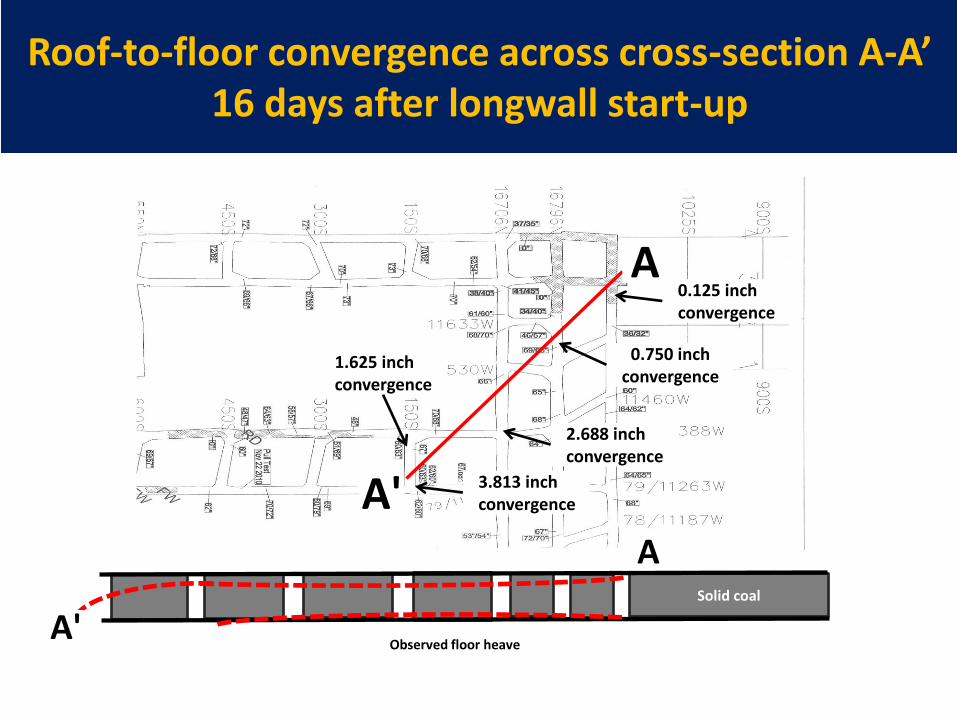
Roof-to-floor convergence across cross-section A-A’ 16 days after longwall start-up
A
A'
Solid coal
A'
A
0.125 inch convergence
0.750 inch convergence
2.688 inch convergence
3.813 inch convergence
1.625 inch convergence
Observed floor heave
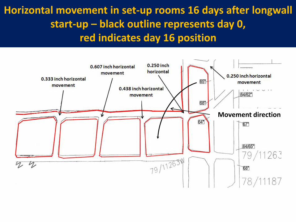
Horizontal movement in set-up rooms 16 days after longwall start-up – black outline represents day 0,
red indicates day 16 position
Movement direction
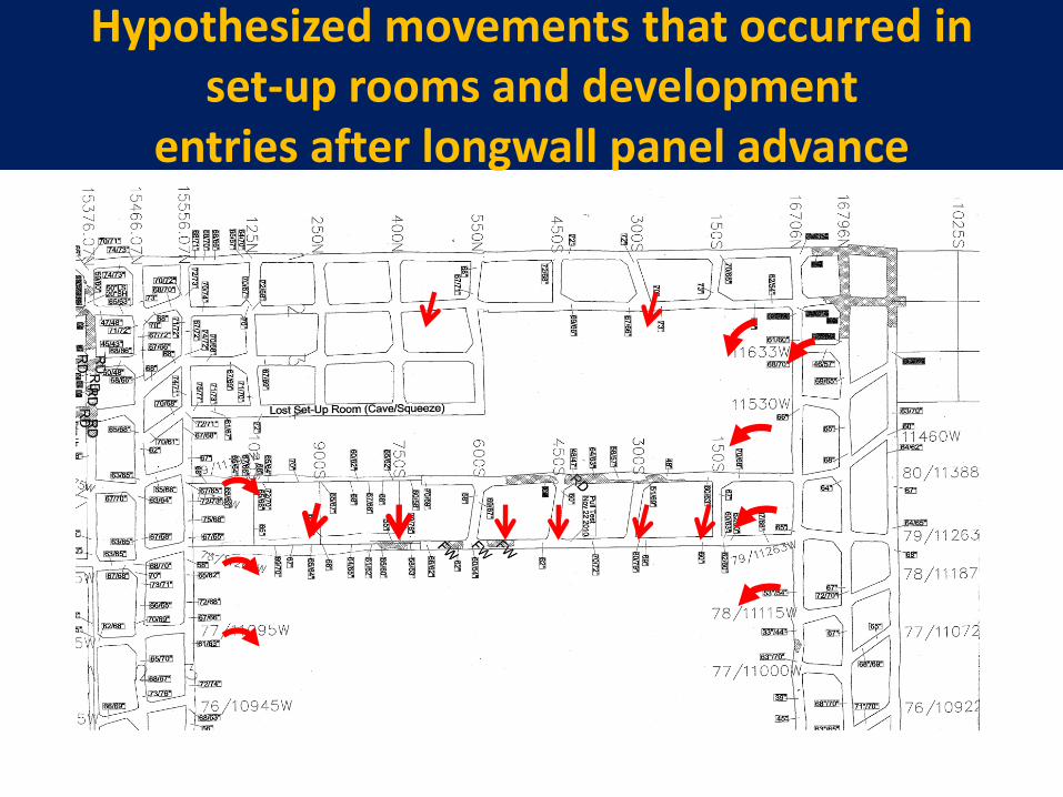
Hypothesized movements that occurred in set-up rooms and development
entries after longwall panel advance
FLAC3D 3.00
Itasca Consulting Group, Inc.Minneapolis, MN USA
Step 81275 Model Perspective20:02:12 Thu Aug 04 2011
Center: X: 1.200e+003 Y: 9.500e+002 Z: 5.294e+001
Rotation: X: 70.000 Y: 0.000 Z: 0.000
Dist: 1.146e+004 Mag.: 1.95Ang.: 22.500
Axes Linestyle
X
Y
Z
Contour of Z-Displacement Magfac = 1.000e+000 Null zones only
-6.0913e+000 to -6.0000e+000-6.0000e+000 to -5.0000e+000-5.0000e+000 to -4.0000e+000-4.0000e+000 to -3.0000e+000-3.0000e+000 to -2.0000e+000-2.0000e+000 to -1.0000e+000-1.0000e+000 to 0.0000e+000 0.0000e+000 to 6.2093e-002
Interval = 1.0e+000
Magnified area
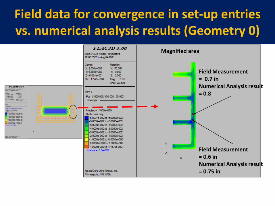
Field Measurement = 0.7 in Numerical Analysis result = 0.8
Field Measurement = 0.6 in Numerical Analysis result = 0.75 in
Field data for convergence in set-up entries vs. numerical analysis results (Geometry 0)
FLAC3D 3.00
Itasca Consulting Group, Inc.Minneapolis, MN USA
Step 221091 Model Perspective20:32:06 Thu Aug 04 2011
Center: X: 1.667e+003 Y: 9.500e+002 Z: 5.296e+001
Rotation: X: 80.000 Y: 0.000 Z: 0.000
Dist: 1.146e+004 Mag.: 1.25Ang.: 22.500
Contour of Z-Displacement Magfac = 1.000e+000 Null zones only
-6.0973e+000 to -6.0000e+000-6.0000e+000 to -5.0000e+000-5.0000e+000 to -4.0000e+000-4.0000e+000 to -3.0000e+000-3.0000e+000 to -2.0000e+000-2.0000e+000 to -1.0000e+000-1.0000e+000 to 0.0000e+000 0.0000e+000 to 9.7040e-002
Interval = 1.0e+000
Axes Linestyle X
Y
Z
Magnified area
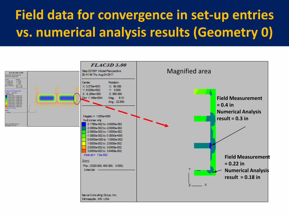
Field Measurement = 0.22 in Numerical Analysis result = 0.18 in
Field Measurement = 0.4 in Numerical Analysis result = 0.3 in
Field data for convergence in set-up entries vs. numerical analysis results (Geometry 0)
FLAC3D 3.00
Itasca Consulting Group, Inc.Minneapolis, MN USA
Step 221091 Model Perspective20:32:06 Thu Aug 04 2011
Center: X: 1.667e+003 Y: 9.500e+002 Z: 5.296e+001
Rotation: X: 80.000 Y: 0.000 Z: 0.000
Dist: 1.146e+004 Mag.: 1.25Ang.: 22.500
Contour of Z-Displacement Magfac = 1.000e+000 Null zones only
-6.0973e+000 to -6.0000e+000-6.0000e+000 to -5.0000e+000-5.0000e+000 to -4.0000e+000-4.0000e+000 to -3.0000e+000-3.0000e+000 to -2.0000e+000-2.0000e+000 to -1.0000e+000-1.0000e+000 to 0.0000e+000 0.0000e+000 to 9.7040e-002
Interval = 1.0e+000
Axes Linestyle X
Y
Z
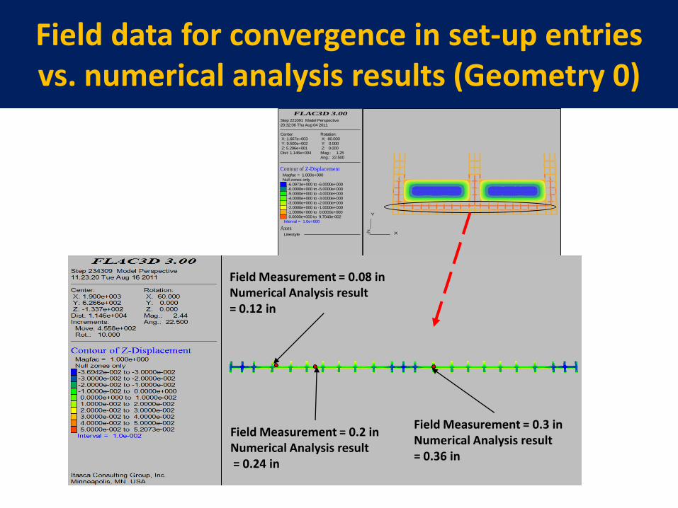
Field Measurement = 0.08 in Numerical Analysis result = 0.12 in
Field Measurement = 0.2 in Numerical Analysis result = 0.24 in
Field Measurement = 0.3 in Numerical Analysis result = 0.36 in
Field data for convergence in set-up entries vs. numerical analysis results (Geometry 0)
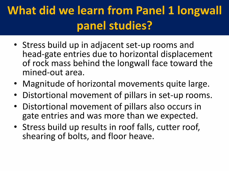
What did we learn from Panel 1 longwall panel studies?
• Stress build up in adjacent set-up rooms and head-gate entries due to horizontal displacement of rock mass behind the longwall face toward the mined-out area.
• Magnitude of horizontal movements quite large. • Distortional movement of pillars in set-up rooms. • Distortional movement of pillars also occurs in
gate entries and was more than we expected. • Stress build up results in roof falls, cutter roof,
shearing of bolts, and floor heave.
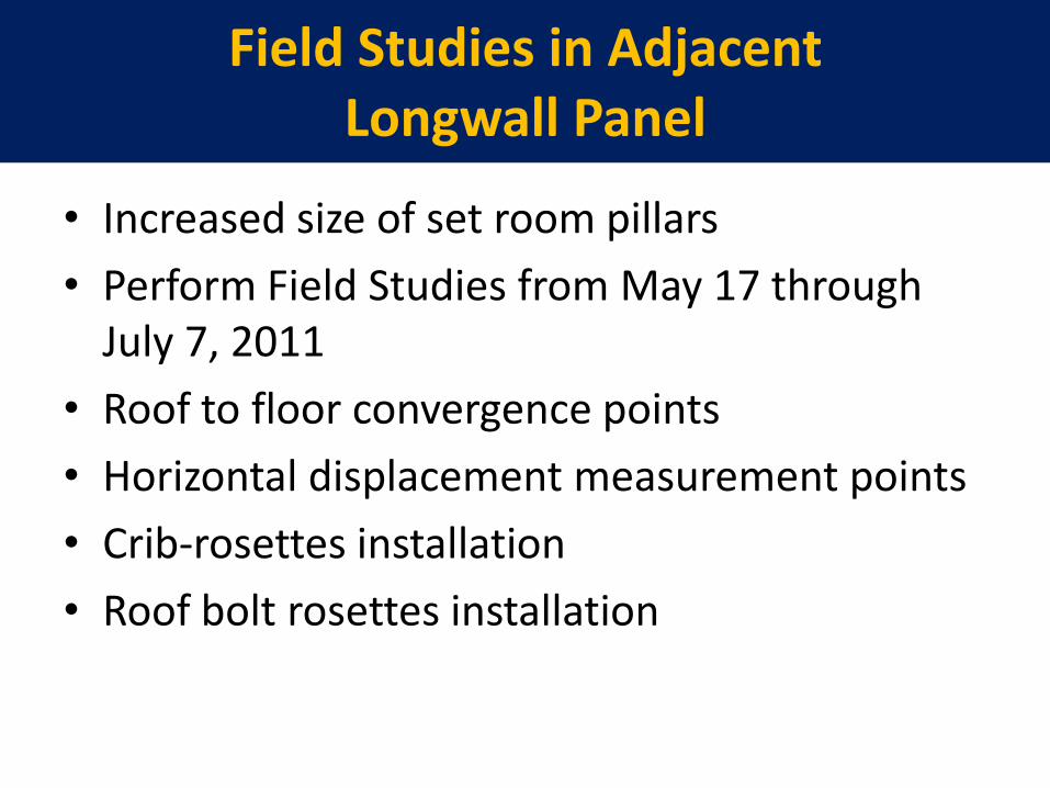
Field Studies in Adjacent Longwall Panel
• Increased size of set room pillars
• Perform Field Studies from May 17 through July 7, 2011
• Roof to floor convergence points
• Horizontal displacement measurement points
• Crib-rosettes installation
• Roof bolt rosettes installation
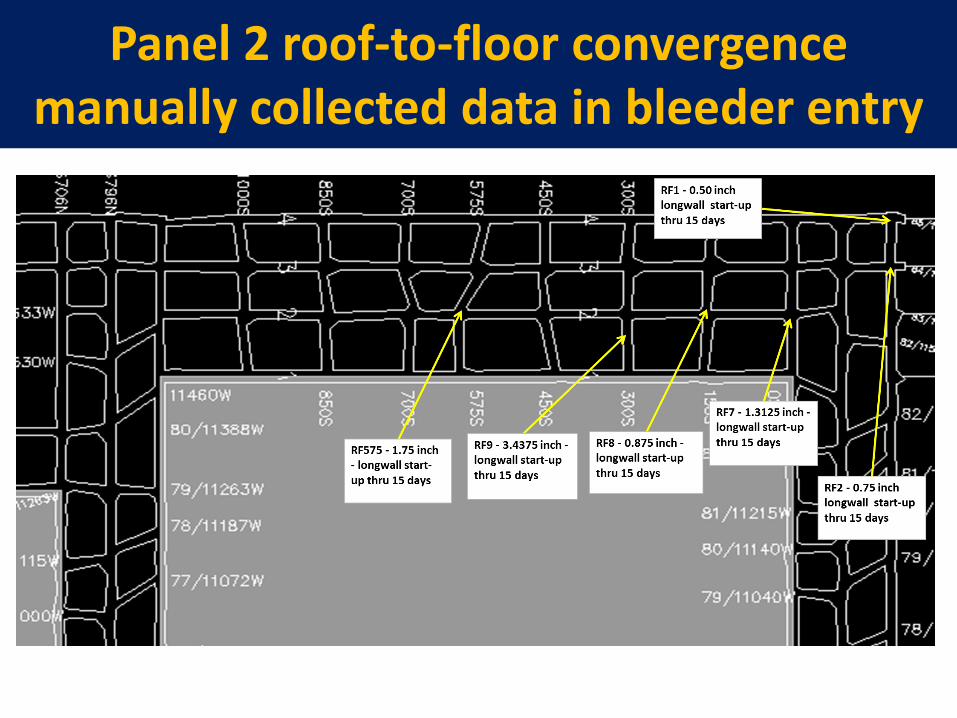
Panel 2 roof-to-floor convergence manually collected data in bleeder entry
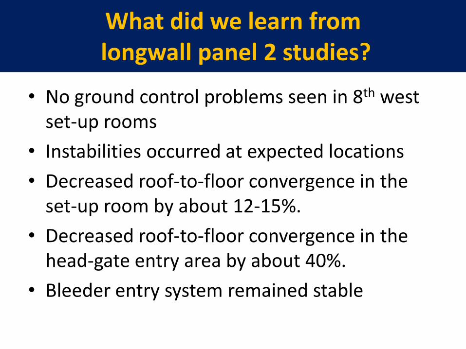
What did we learn from longwall panel 2 studies?
• No ground control problems seen in 8th west set-up rooms
• Instabilities occurred at expected locations
• Decreased roof-to-floor convergence in the set-up room by about 12-15%.
• Decreased roof-to-floor convergence in the head-gate entry area by about 40%.
• Bleeder entry system remained stable

Mine 2 Studies (December 15, 2011 through February 14, 2012)
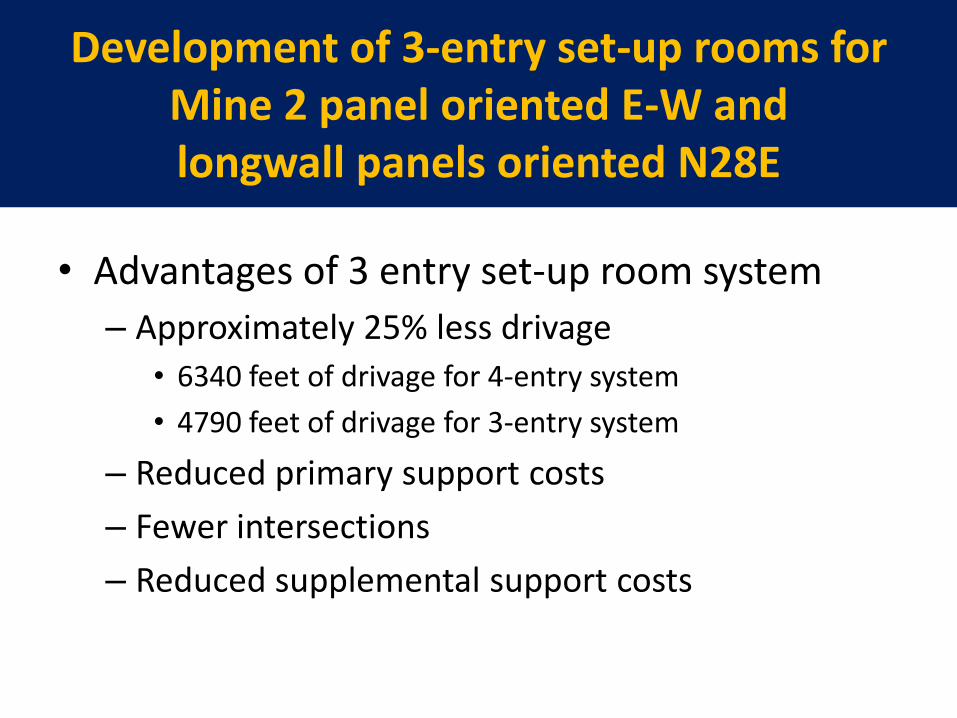
Development of 3-entry set-up rooms for Mine 2 panel oriented E-W and longwall panels oriented N28E
• Advantages of 3 entry set-up room system
– Approximately 25% less drivage
• 6340 feet of drivage for 4-entry system
• 4790 feet of drivage for 3-entry system
– Reduced primary support costs
– Fewer intersections
– Reduced supplemental support costs
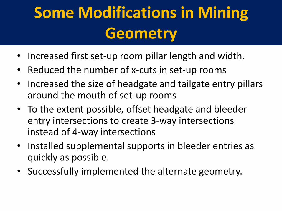
Some Modifications in Mining Geometry
• Increased first set-up room pillar length and width.
• Reduced the number of x-cuts in set-up rooms
• Increased the size of headgate and tailgate entry pillars around the mouth of set-up rooms
• To the extent possible, offset headgate and bleeder entry intersections to create 3-way intersections instead of 4-way intersections
• Installed supplemental supports in bleeder entries as quickly as possible.
• Successfully implemented the alternate geometry.
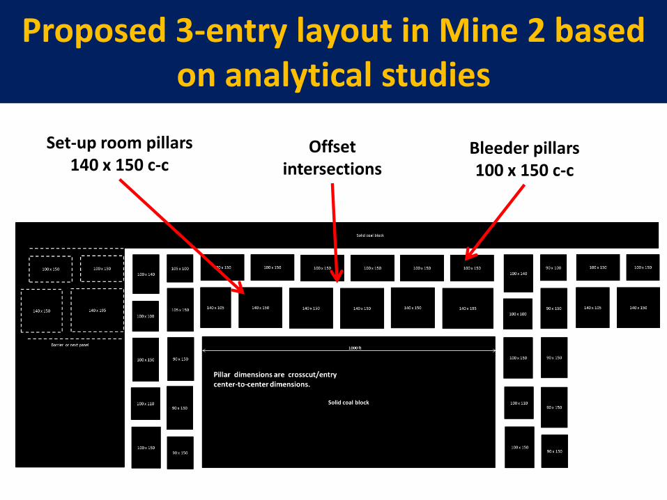
Proposed 3-entry layout in Mine 2 based on analytical studies
Bleeder pillars 100 x 150 c-c
Set-up room pillars 140 x 150 c-c
Offset intersections
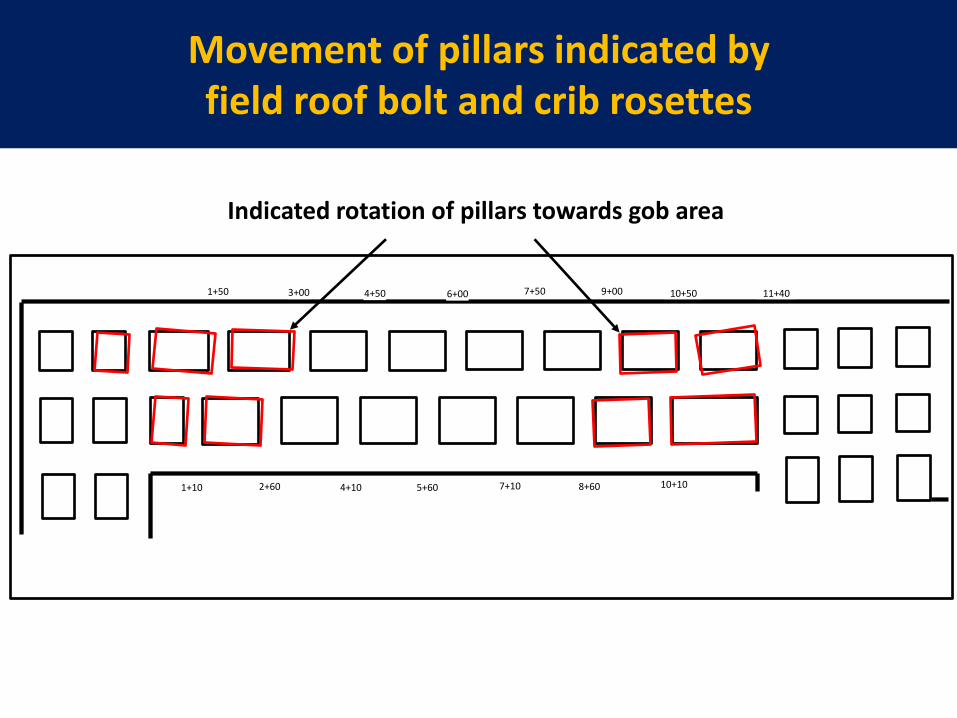
Movement of pillars indicated by field roof bolt and crib rosettes
11+40 1+50 3+00 4+50 9+00 6+00 7+50 10+50
1+10 2+60 4+10 5+60 7+10 8+60 10+10
Indicated rotation of pillars towards gob area
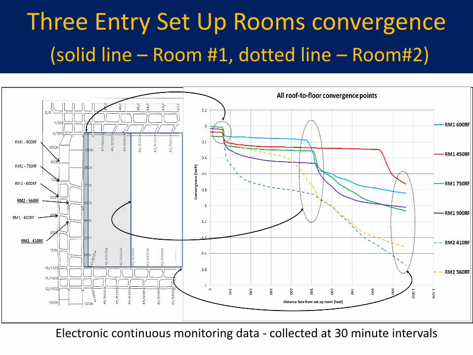
Three Entry Set Up Rooms convergence (solid line – Room #1, dotted line – Room#2)
Electronic continuous monitoring data - collected at 30 minute intervals
What have we learnt from Mine 2 studies in the field)
• 3-entry system is viable with increased pillar sizes
• No ground control problems in set-up rooms.
• Rotation of pillars still occurs to a small degree
• Convergence in the bleeder entry increases after about 40 feet of longwall advance then stabilizes, then increases again at about 500 feet of advance
Ground Control Studies for Development Entries and Intersections
(60 ° vs. 90° staggered and non-staggered
crosscuts intersections)
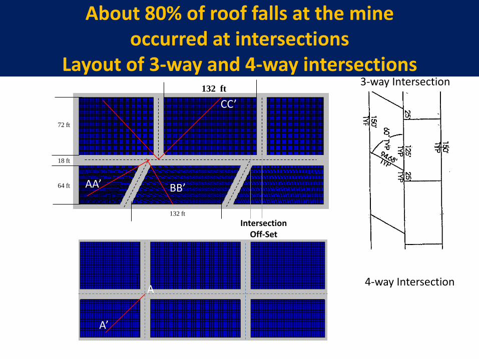
A’
A
72 ft
64 ft
18 ft
132 ft
132 ft
AA’ BB’
CC’
Intersection Off-Set
3-way Intersection
4-way Intersection
About 80% of roof falls at the mine occurred at intersections
Layout of 3-way and 4-way intersections
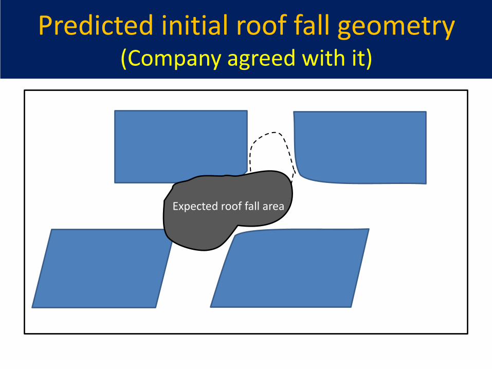
Predicted initial roof fall geometry (Company agreed with it)
Expected roof fall area
Gate entries development
• Minimize angled cross-cuts.
• For staggered cross-cuts, require minimum 40 feet and preferably 45 feet offset.
• Have successfully implemented these concepts in the field.
• Uneven size pillars in development entries – make belt entry pillar larger.
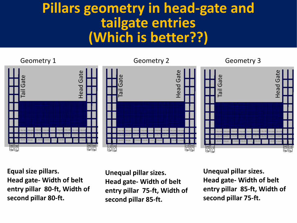
Equal size pillars. Head gate- Width of belt entry pillar 80-ft, Width of second pillar 80-ft.
Unequal pillar sizes. Head gate- Width of belt entry pillar 75-ft, Width of second pillar 85-ft.
Unequal pillar sizes. Head gate- Width of belt entry pillar 85-ft, Width of second pillar 75-ft.
Pillars geometry in head-gate and tailgate entries
(Which is better??) Ta
il G
ate
Hea
d G
ate
Tail
Gat
e
Hea
d G
ate
Tail
Gat
e
Hea
d G
ate
Geometry 1 Geometry 2 Geometry 3
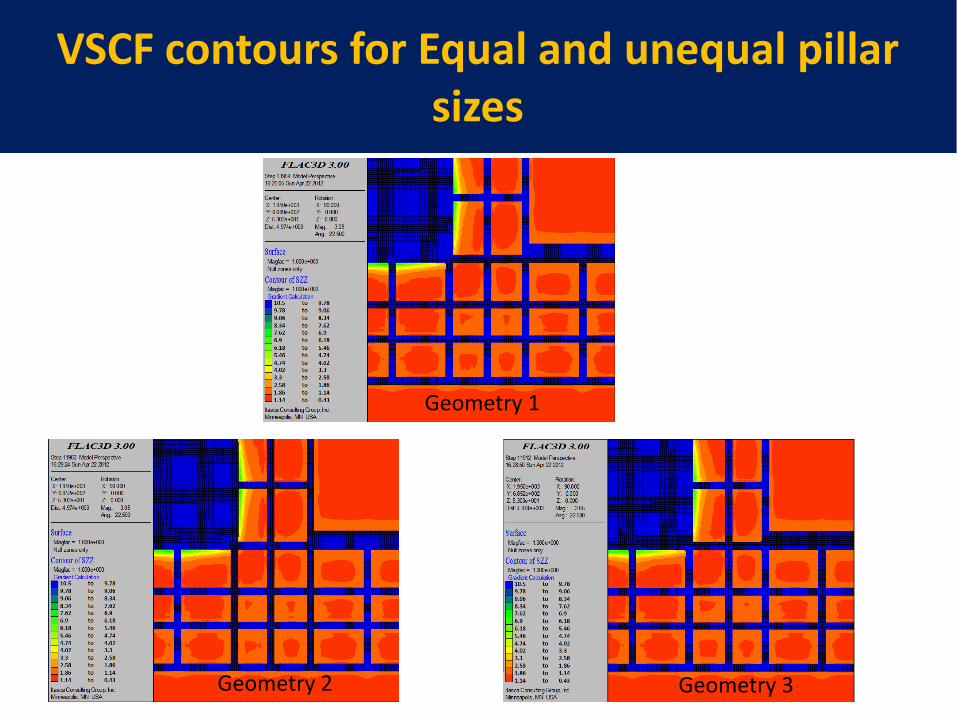
VSCF contours for Equal and unequal pillar sizes
Geometry 3 Geometry 2
Geometry 1
• Mining company currently uses Geometry III.
• Numerical analysis suggests that pillar geometry II would be better from ground stability point of view.
• Results have been discussed with company.
• Implementation of this concept is currently being considered by the company.
Modeling Results
Stress and Displacement Comparisons for Regular and Realistic Field Geometries
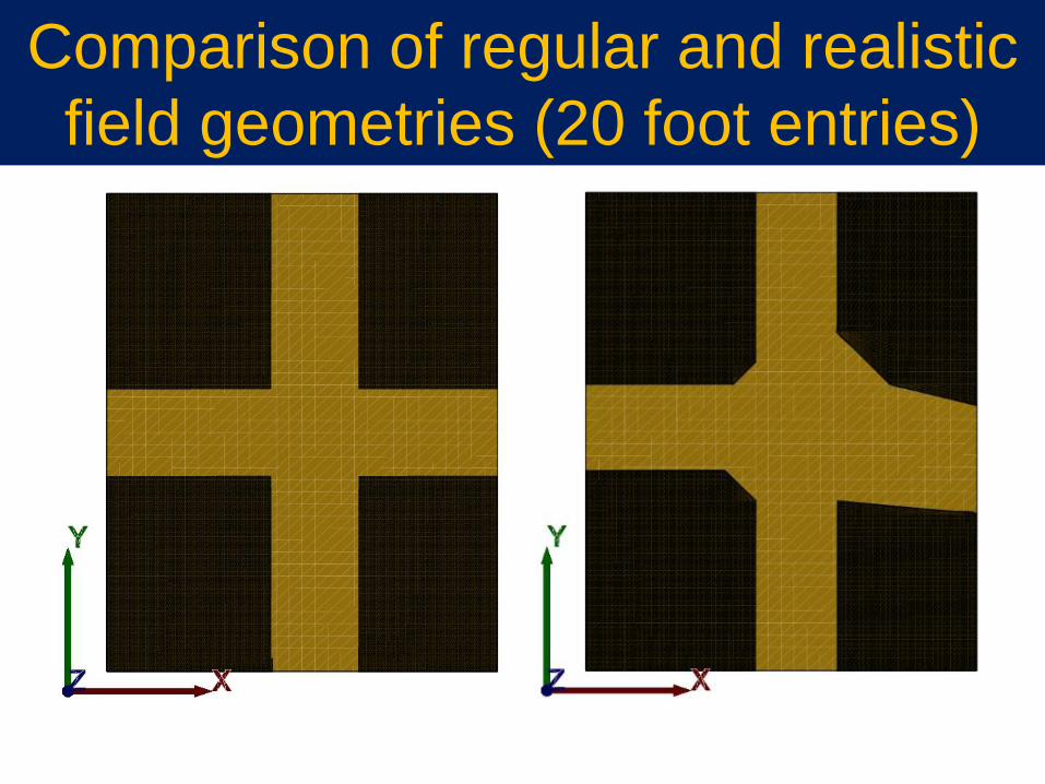
Comparison of regular and realistic
field geometries (20 foot entries)
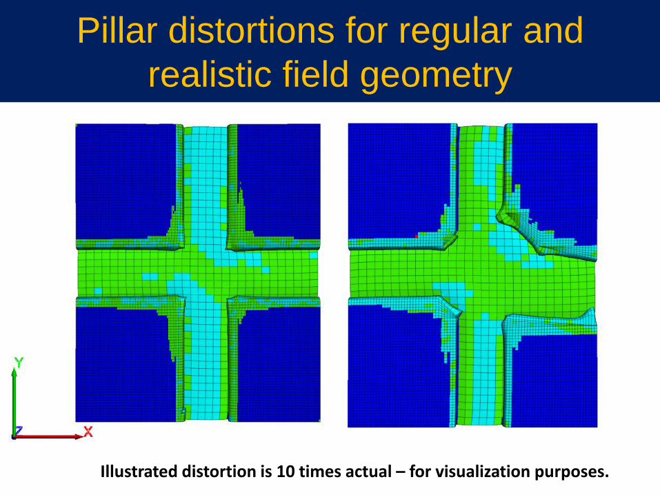
Pillar distortions for regular and
realistic field geometry
Illustrated distortion is 10 times actual – for visualization purposes.
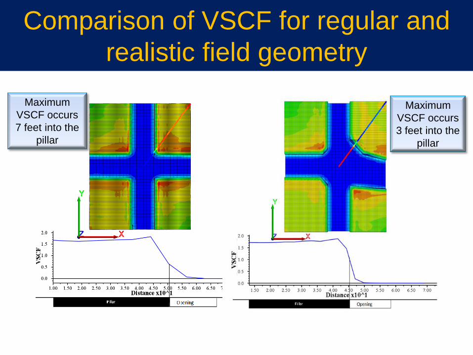
Comparison of VSCF for regular and
realistic field geometry
Maximum
VSCF occurs
7 feet into the
pillar
Maximum
VSCF occurs
3 feet into the
pillar
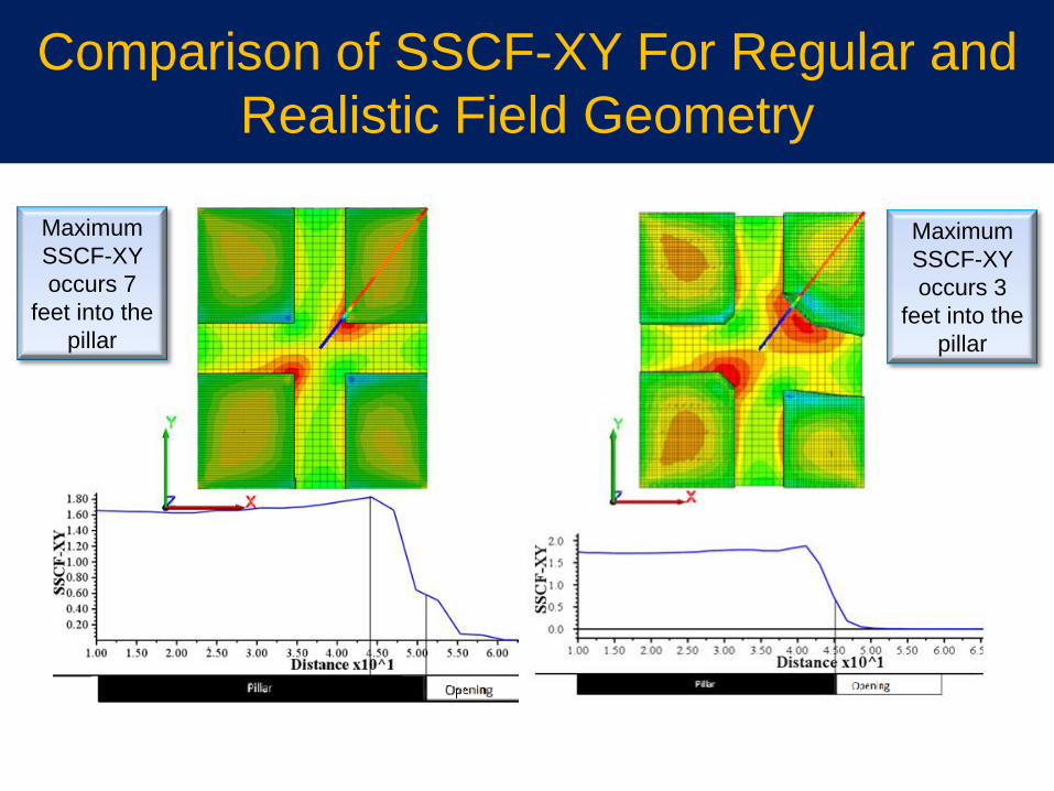
Comparison of SSCF-XY For Regular and
Realistic Field Geometry
Maximum
SSCF-XY
occurs 7
feet into the
pillar
Maximum
SSCF-XY
occurs 3
feet into the
pillar
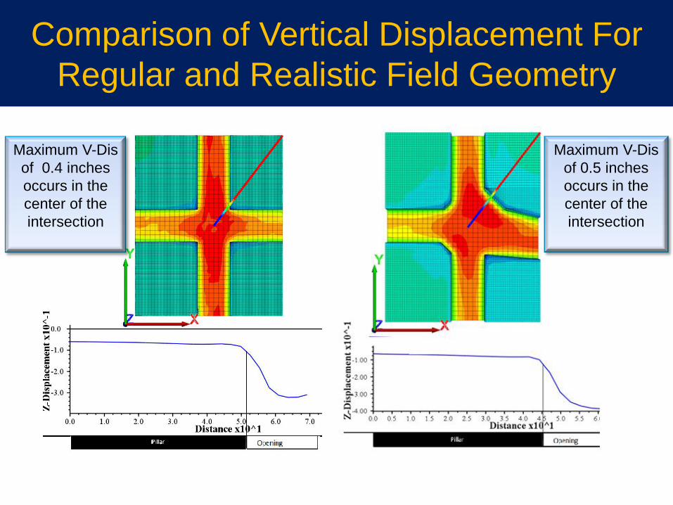
Comparison of Vertical Displacement For
Regular and Realistic Field Geometry
Maximum V-Dis
of 0.4 inches
occurs in the
center of the
intersection
Maximum V-Dis
of 0.5 inches
occurs in the
center of the
intersection
• Strong collaborative engineering effort for planning efficient and safe longwall mining layouts.
• A numerical model has been developed and validated for structural analysis of longwall mining layouts at the mine.
• Notable success over last 12- months to improve stability of set-up rooms and development entries through implementation of new concepts.
• Additional improvements are expected at New Era mine next 12-months.
Concluding Remarks

Thank you!! Questions and Comments??