xcite owner’s manual · xcite owner’s manual ... hydraulic power supply, any reference to the...
TRANSCRIPT

RDS - 1
Reso-notTM Damping SystemXCITE
1300T-1 System1300T-2 System1300T-3 System
XCITEOwner’s Manual
Xcite Systems Corporation 675 Cincinnati Batavia Pike Cincinnati, Ohio 45245Tel: (239) 980-9093 Fax: (239) 985-0074 Email: [email protected] Web: www.xcitesystems.com

PrefaceXCITE
Copyright 1997Xcite Systems Corporation
This document contains proprietary information of Xcite Systems Corporation and istendered subject to the conditions that the information (a) be retained in confidence (b) notbe reproduced or copied in whole or in part and (c) not be used or incorporated into anyproduct except under an express written agreement with Xcite Systems Corporation.
P - 2

PrefaceXCITE
P -
Table of Contents
1. Warranty .............................................................................................................P-71.1. Xcite Products ...........................................................................................P-71.2. Third Party Hardware Products ..................................................................P-71.3. IMPORTANT LIMITATIONS ........................................................................P-71.4. NOTICE OF LIMITED WARRANTY ............................................................P-8
2. Receiving ...........................................................................................................P-82.1. Receiving Inspection Procedure.................................................................P-82.2. Shipping Container ....................................................................................P-8
1300T Torsional Exciter SystemsSetup and Operation
1. Introduction .................................................................................................. S&O-12. System Description ..................................................................................... S&O-13. Setup Procedure.......................................................................................... S&O-1
3.1. Mounting the Exciter Head ....................................................................S&O-13.2. Hydraulic Power Supply Commissioning Procedure ..............................S&O-33.3. Starting the Hydraulic Power Supply......................................................S&O-43.4. Hydraulic Hookup .................................................................................S&O-53.5. Cable Hookup ......................................................................................S&O-6
4. Operation Procedure ................................................................................... S&O-64.1. Switch Settings .....................................................................................S&O-6
5. Shutdown Procedures ................................................................................ S&O-86. Troubleshooting .......................................................................................... S&O-87. Storage Instructions .................................................................................... S&O-8
1300T Series Torsional Exciter Heads
1. Introduction .......................................................................................... 1300TEH-12. General Description ............................................................................. 1300TEH-1
2.1. Rotary Actuator ............................................................................. 1300TEH-12.2. Servo-Valve ................................................................................. 1300TEH-12.3. Torque Transducer ........................................................................ 1300TEH-1
3. Specifications ....................................................................................... 1300TEH-24. Head Operating Instructions ................................................................ 1300TEH-25. Theory of Operation ............................................................................. 1300TEH-2
5.1. Electric Circuit Description ........................................................... 1300TEH-25.2. Hydraulic Circuit Description ......................................................... 1300TEH-2
6. Maintenance .......................................................................................... 1300TEH-37. Drawings ............................................................................................... 1300TEH-3
3

PrefaceXCITE
P -
1302C Hydraulic Power Supply
1. Introduction ........................................................................................ 1302CHPS-12. Theory of Operation .......................................................................... 1302CHPS-1
2.1. Circuit Description (Hydraulic) Drawing B-30066 ....................... 1302CHPS-12.2. Circuit Description (Electric) Drawing B-30068 .......................... 1302CHPS-1
3. Description ......................................................................................... 1302CHPS-33.1. Major Components .................................................................... 1302CHPS-33.2. Control Components .................................................................. 1302CHPS-33.3. Monitoring Devices .................................................................... 1302CHPS-3
4. Care and Maintenance ...................................................................... 1302CHPS-44.1. Operating Care .......................................................................... 1302CHPS-44.2. Maintenance .............................................................................. 1302CHPS-5
5. Troubleshooting ................................................................................ 1302CHPS-55.1. Unit Overheats ........................................................................... 1302CHPS-65.2. Pump de-energizes ................................................................... 1302CHPS-6
6. Specifications .................................................................................... 1302CHPS-67. Drawings ............................................................................................ 1302CHPS-6
Master Controller
1. Introduction .....................................................................................................MC-12. Theory of Operation .......................................................................................MC-1
2.1. Configurations ........................................................................................MC-12.1.1. Single Loop ............................................................................MC-12.1.2. Dual Loop...............................................................................MC-1
3. Description ......................................................................................................MC-23.1. Front Panel .............................................................................................MC-3
3.1.1. Static Signal Level Meter (M-101) ...........................................MC-33.1.2. Static Set Point (R301) ...........................................................MC-33.1.3. Dynamic Signal Level Meter (M-102) ......................................MC-33.1.4. Dynamic Set Point (R303) ......................................................MC-33.1.5. Excitation Mode (SW304) .......................................................MC-33.1.6. Interlock (L301) .......................................................................MC-43.1.7. Dither - ON/ OFF (SW308) .....................................................MC-43.1.8. Static Set Point (R301) ...........................................................MC-43.1.9. Static Gain .............................................................................MC-43.1.10. Load Cell ................................................................................MC-53.1.11. Calibrate/ Operate (SW307) ...................................................MC-53.1.12. Power (SW301) ......................................................................MC-53.1.13. Pump .....................................................................................MC-63.1.14. Dynamic Set Point (R303) ......................................................MC-63.1.15. Frequency Range - HIGH/ LOW (SW309) ...............................MC-6
4

PrefaceXCITE
P -
3.2. Rear Panel .............................................................................................MC-63.2.1. Exciter Head (J305) ................................................................MC-63.2.2. Displacement (J311) ..............................................................MC-63.2.3. Calibration Resistor (J304) .....................................................MC-63.2.4. Static Preload (SW310) ..........................................................MC-63.2.5. Interlock (J306) .......................................................................MC-73.2.6. Power (J307) ..........................................................................MC-73.2.7. Fuse (F301) ...........................................................................MC-73.2.8. Program Input (J308) ..............................................................MC-73.2.9. Controlled Variable - Static .....................................................MC-83.2.10. Controlled Variable - Dynamic ................................................MC-83.2.11. Compression Output (J310) ....................................................MC-93.2.12. Standby Level (R313) .............................................................MC-93.2.13. Load Cell Output (J303) ..........................................................MC-93.2.14. Power Amp - INT/ EXT (SW312) .............................................MC-93.2.15. Power Amp - Input (J312) .......................................................MC-93.2.16. EXT Set Point - Static (J313) ................................................MC-103.2.17. EXT Set Point - Dynamic (J314) ........................................... MC-11
4. Operation ....................................................................................................... MC-114.1. Concept of Operation ........................................................................... MC-114.2. System Interconnection .........................................................................MC-124.3. Operation - Force Control .....................................................................MC-12
4.3.1. Set Controls .........................................................................MC-124.3.2. Depress the Power Switch ...................................................MC-134.3.3. Adjust Load Cell ...................................................................MC-134.3.4. Depress Pump Start Button ..................................................MC-13
4.4. Operation - Displacement Control .........................................................MC-144.4.1. Set Controls .........................................................................MC-14
4.5. Operation - External Variable ................................................................MC-154.6. Computer Control - External Set Points (Static and Dynamic)................MC-15
5. Theory of Operation .....................................................................................MC-165.1. Circuit Descriptions ..............................................................................MC-16
5.1.1. VR101 (Voltage Regulator) ...................................................MC-165.1.2. SW310 (Preload Switch) ......................................................MC-165.1.3. A109 (Amplifier) ...................................................................MC-165.1.4. A104 and A105 (Static Control Loop) ...................................MC-175.1.5. A401 and A402 (Dynamic Loop) ..........................................MC-175.1.6. A107 (Inverter Buffer) ............................................................MC-185.1.7. A106 and U103 (Peak Detector Circuit) ...............................MC-18
6. Specifications ...............................................................................................MC-197. Drawings .......................................................................................................MC-198. Parts List .......................................................................................................MC-21
5
PrefaceXCITE
P -
9. Calibration .....................................................................................................MC-269.1. Equipment Needed...............................................................................MC-269.2. Master Controller ..................................................................................MC-27
9.2.1. Meter Zero Adjustments ........................................................MC-279.2.2. +/-15 Volt Supply Check........................................................MC-279.2.3. +/- 60 Volt Supply Verification ...............................................MC-289.2.4. Load Cell Excitation Voltage Verification ...............................MC-289.2.5. Master Controller Board 110-04 Calibration Procedure .........MC-289.2.6. Master Controller Board 110-02 Calibration Procedure .........MC-319.2.7. Master Controller Board 110-01 Calibration Procedure .........MC-31
9.3. Exciter Head Calibration Procedure ......................................................MC-389.3.1. Load Cell Amplifier Calibration .............................................MC-389.3.2. Static Loop Gain Calibration .................................................MC-409.3.3. Static Set Point Level Calibration .........................................MC-429.3.4. High Frequency Dynamic Level Calibration ...........................MC-429.3.5. Low Frequency Dynamic Calibration.....................................MC-43
9.4. Displacement Calibration Procedure ....................................................MC-449.4.1. LVDT Symmetry Verification and Adjustment ........................MC-449.4.2. Displacement Zero Calibration .............................................MC-459.4.3. Displacement Scaling Calibration .........................................MC-459.4.4. Final External Static Control Variable Calibration ..................MC-459.4.5. Dynamic Displacement Calibration .......................................MC-459.4.6. External Static and Dynamic Set Point Calibration ................MC-46
6

PrefaceXCITE
1. Warranty
1.1. Xcite ProductsXcite Systems Corporation warrants that any Xcite manufactured product willconform to Xcite’s written specifications applicable at the time of shipment andwill be free from defects in material or workmanship for one year. During theXcite warranty period, Xcite, or its agent, will repair or replace, at its option,any defective product when returned to the factory, freight prepaid by thebuyer, and will return the product freight collect. Xcite assumes no liability forloss or damage during shipment to and from the factory. If insurance on thereturn shipment is required, it must be specified by the buyer.
1.2. Third Party Hardware ProductsXcite will transfer the original manufacturer’s warranty for third partyhardware (not manufactured by Xcite) to the buyer. The warranty policy ofthose companies in effect at the time of shipment will apply to their products,and Xcite assumes no additional responsibility. Xcite will indicate on itsinvoice the warranty terms relevant to specific Third Party Hardware items.
1.3. IMPORTANT LIMITATIONS
1.3.1. The warranty period commences upon the day of shipment fromXcite without respect to any acceptance criteria or paymentprovisions in any particular contract.
1.3.2. The warranty period does not apply to normal wear items or todamage caused by abuse, neglect or accident.
1.3.3. Xcite’s responsibility is limited to the above obligations, andXcite cannot be held responsible for special or consequential orother damages.
ALL OTHER EXPRESS OR IMPLIED WARRANTIES, INCLUDINGMERCHANTABILITY AND FITNESS FOR PURPOSE, ARE EXCLUDED.
P - 7
PrefaceXCITE
1.4. NOTICE OF LIMITED WARRANTYTHE FOLLOWING ITEM(S) INCLUDED IN THIS XCITE PRODUCT ORSYSTEM ARE EXCLUDED FROM OUR ONE YEAR WARRANTY BECAUSETHEY ARE NORMAL WEAR ITEMS:
1) All system seals2) Servovalve*
*The servovalve used on this system will be damaged if any particle(s) largerthan 10 microns are permitted to enter the valve. Extreme care should beexercised when the hydraulic hoses are connected to ensure no foreignparticles enter the connections. It is recommended to always wipe thehydraulic couplings with lint free towel before making connections. Alwaysuse the protective dust covers on the hoses (the dust covers can beconnected together when operating the system). Any damage to theservovalve as a result of contamination is specifically excluded from warranty.
2. Receiving
2.1. Receiving Inspection ProcedureXcite Systems Corporation products are shipped in a manner designed toprotect against all normal shipping hazards. Immediately upon receipt,inspect all equipment and note any visible damage. In accordance with theinstructions in this manual, test its functional operation. Keep all documentsin relation to this shipment. If shipping damage is apparent, file a claim withthe carrier’s claim agent and send a copy to Xcite Customer Service. Besure to include the product name, model number and serial number on allcorrespondence.
2.2. Shipping ContainerShipping containers are supplied with all Xcite products. Store thesecontainers and inserts in a dry area for possible later use.
P - 8

1300T Torsional Exciter SystemSetup and Operation

S&O - 1
XCITE 1300T Setup and Operation
1300T Torsional Exciter SystemApplies to 1300T-1, 1300T-2 and 1300T-3
1. IntroductionThe function of this system is to impart a controlled torque into structures such asrotors, axles and engines. The torque generation is accomplished by a closed loopelectrohydraulic system which can apply a static preload in addition to dynamic torqueup to 1000 Hz under either sine or random conditions.
The static control loop of the system utilizes either the built-in DisplacementTransducer (RVDT) or strain gage torque cell as feedback and controls the staticposition of the exciter rotor while the dynamic control loop utilizes the built-in torquecell as feedback to measure and control the dynamic torque applied to the structureunder test.
2. System DescriptionThis manual contains a section of detailed information on each of these componentsand the user should familiarize himself or herself with this information before using thesystem. The 1300T torsional excitation systems are configured as follows:
1300T-1 System 1300T-2 System 1300T-3 System
Hydraulic Power Supply 1301 or 1302 1301 or 1302 1301 or 1302Master Controller 1304-Mod4 1304-Mod4 1304-Mod4Exciter Head 1307-15-Tor 1314-15-Tor 1318-15-Tor
If the user has purchased the Exciter Head and Master Controller without an XciteHydraulic Power Supply, any reference to the power supply in this manual applies towhatever source of hydraulic power the user has elected.
3. Setup Procedure
3.1. Mounting the Exciter Head
3.1.1. The exciter head may be mounted in any orientation but care mustbe taken to provide strain relief on hoses and cables if the unit ismounted at heights which would add significant loads to the hosesand cables.
S&O - 2
XCITE 1300T Setup and Operation
3.1.2. The exciter mounting base has clearance holes for mounting.Secure the unit so that it will not “walk” when exciting resonantfrequencies of the structure.
3.1.3. CAUTION! Care must be taken that the exciter is firmly andsquarely attached to the back up fixturing. Any clearances ordead zones in the attachment or dynamics of any fixtures willcause distortion of the force waveform.
3.1.4. The Exciter Head may be used with either Static Torque Controlor Static Angular Displacement Control. When choosing the typeof control the following conditions should be considered:
HIGH STATIC STIFFNESS: if the Static Torsional Stiffness of thetest structure is such that less than 1
o or 2
o of motion will be
experienced with full Load Torque, then it is advisable to use theexciter with the Master Controller set to “INTERNAL” STATICCONTROLLED VARIABLE (see 4.1.1.) This setting will providefor static torque feedback to the Master Controller and statictorque will be the static controlled variable.
LOW STATIC STIFFNESS: if the Static Torsional Stiffness of thetest structure is such that static motion of over 2
o to 50
o is expected
(ie. free-free) then it is advisable to use the exciter with the MasterController set to “EXTERNAL” STATIC DISPLACEMENTCONTROL (see 4.1.1.) This setting will provide for static angulardisplacement feedback to the Master Controller and angulardisplacement will be the static controlled variable.
Hint: When attempting to mount the torque cell to the teststructure bolt hole pattern, use the exciter head in the“EXTERNAL” STATIC DISPLACEMENT control mode. Underthese conditions, the actuator can be easily rotated to align theload cell mounting holes for proper fit of the structure’s mountingbolts (customer supplied).
Note: When using the exciter in “EXTERNAL” STATICDISPLACEMENT, the position of the rotary actuator with thesystem in “STANDBY” is full counter clockwise (ccw) when lookingat the actuator from the end that does not have the Torque LoadCell mounted. When the Master Controller is switched to STATIC,the rotary actuator will rotate clockwise (cw) as determined by theSTATIC SETPOINT control knob.

S&O - 3
XCITE 1300T Setup and Operation
3.1.5. PROCEDURE FOR CHANGING FROM STATIC DISPLACEMENTCONTROL TO STATIC TORQUE CONTROLIf after aligning and affixing the torque cell bolt holes to the teststructure by using static displacment control it is desired to controlstatic torque, the following procedure should be followed to start upthe system.
1. Leave the Excitation mode selector in the STATIC position2. Press PUMP OFF and turn off the Hydraulic Power Supply3. Switch the interlock selector switch mounted just below the
red interlock lamp to the OFF position (SW in the downposition)
4. Turn the static setpoint knob to the Zero (0) setting5. Change the STATIC CONTROLLED VARIABLE switch on
the rear panel to INTERNAL6. Restart the Hydraulic Power Supply and the system will start
up in the STATIC TORQUE MODE with Zero torque applied7. Set the static torque to the desired torque setting by
adjusting the static setpoint knob
3.2. Hydraulic Power Supply Commissioning Procedure
3.2.1. Remove all packing material from inside and outside the pumpcabinet.
3.2.2. Locate the main power cable attached to the Electrical Control Box.
3.2.3. Fill oil reservoir with new, clean Mobile DTE-24/25 hydraulic fluid(or equal). Check oil sight gage for proper oil level. (Approximately40 gallons)
3.2.4. Connect main power cable to main electrical service. Be sure thatthe proper voltage is applied to the Hydraulic Power Supply. The 3phase wire colors are Red, Black and White. Ground (Green Wire)must be connected or ground loops will exist in instrumentationcausing 60 Hz or 50 Hz signal noise.
3.2.5. For a 1302 supply, which is water cooled, connect a source ofwater supply to the water/oil heat exchanges mounted at the rearend of the Power Supply. The inlet water supply should have aminimum water pressure of 50PSI, a minimum flow capacity of8 GPM and a maximum water temperature of 70°F.

S&O - 4
XCITE 1300T Setup and Operation
The return line from the water/oil heat exchanger should be con-nected to a suitable water drain.
Note: Water hoses are included if it is desired to nothard plumb the water connection to the water/oil heatexchanger.
Warning: Be sure to always turn on the water supplybefore starting the pump or it will overheat and shutoff for several hours before it can be restarted.
3.2.6. Connect the pump control cable (B-11921) to the Hydraulic PowerSupply and to the rear panel connector of the Master Controller.
3.2.7. Turn on the Main Power Switch (large red/ yellow switch) located onthe front of the Hydraulic Power Supply.
3.2.8. Verify that the yellow PHASE CORRECT light is lit. If not, reversethe Red and Black wires at the main power connection. The pumpwill not start until the “phase correct” lamp isilluminated.
3.2.9. Connect one of the Exciter Head hoses to both the pressure outand return quick disconnects. This procedure effectively “shortcircuits” the output to the return and allows for all entrapped air inthe pump to be removed on initial startup. Remove this connectionafter 5 to 10 minutes of running time.
3.3. Starting the Hydraulic Power Supply
3.3.1. Check to see that the Red EMERGENCY STOP BUTTONlocated on the Power Supply is pulled out. The unit will notstart if this switch is pushed into its STOP MODE.
3.3.2. Push the Red POWER button on the Master Controller. Itshould light up along with the PUMP STOP light.
3.3.3. Push the PUMP START button on the Master Controller and thePower Supply should start up.
WARNING

S&O - 5
XCITE 1300T Setup and Operation
3.3.4. Allow approximately 30 seconds for the pump to prime. There willbe no pressure on the pressure gage because the supply andreturn are connected. (Section 3.2.9.) The pump will exhibit someloud noises as the entraped air is purged. These noises will abateafter 1 or 2 minutes of running time.
After all priming noises have abated, shut off the pump anddisconnect the “shorting” hose. Start the pump back up and itshould come up to 3000PSI. Some additional priming noise mightlast for 1 or 2 minutes and this is normal. After all priming noiseshave abated, the pump should be running smoothly at a pressureof 3000 - 3400PSI.
3.3.5. For a 1301 Supply, which is air cooled, verify that the fan motorlocated in the Hydraulic Power Supply is operating.
Note: the fan is temperature operated and will only turn on whenthe oil temperature is above a preset limit.
3.3.6. The Hydraulic Power Supply is now running correctly.
3.3.7. Push the PUMP STOP button. The power supply will shut downand the PUMP STOP switch will stay lit.
3.3.8. Push the POWER switch of the Master Controller to turn it off.
3.4. Hydraulic Hookup
3.4.1. Connect the Hydraulic Power Supply pressure and return hosesto the Exciter Head pressure and Return hoses via the polarizedquick disconnects supplied with the system hoses.
3.4.2. Take care to maintain cleanliness by always attaching caps to thequick disconnects when disconnected.
3.4.3. When in doubt about hose polarity, the convention is: Supply Pressure - Coupler Supply Return - Nipple
3.4.4. Take care that hoses will not rub against sharp objects whenpulsating.

S&O - 6
XCITE 1300T Setup and Operation
3.5. Cable Hookup
3.5.1. Connect cable C-12202 to the Master Controller rear panelconnector and to the servovalve and Torque Cell of the ExciterHead.
3.5.2. Connect cable C-12201 to the rear panel connector of the MasterController and the displacement connector of the Exciter Head.
Caution: The connector for the Displacement Transducer and theconnector for the Torque Cell is the same size and configuration.Be sure to connect the cables correctly as specified in3.5.1. and 3.5.2.
4. Operation Procedure
4.1. Switch Settings
4.1.1. Set the switches on the back of the Master Controller to the following:
CONTROLLED VARIABLE STATIC (see 3.1.4.) EXTERNAL
(Static DisplacementControl)INTERNAL(Static Torque Control)
DYNAMIC INTERNALSTATIC PRELOAD COMPRESSION/CCWPOWER AMP INTCALIBRATION RESISTOR Plug inserted for
Torque Load Cell

S&O - 7
XCITE 1300T Setup and Operation
4.1.2. Set the switches on the front of the Master Controller to thefollowing:
INTERLOCK(Located below the Red Interlcok Lamp) ON (Up Position)
DITHER OFFSTATIC SETPOINT (see 3.1.4.) 0.0 for static torque
control0.0 for static angulardisplacement control
STATIC GAIN VARIABLE(For DisplacementControl)FIXED(For Torque Control)
VARIABLE GAIN 5.0LOAD CELL OPERATEEXCITATION MODE STANDBY/ RESETFREQUENCY HIGHDYNAMIC SETPOINT 0.0
4.1.3. Connect a 1.0 Vrms variable frequency oscillator to theProgram Input J308. (1 Hz to 1200 Hz)
4.1.4. Press POWER on Master Controller. The POWER light will beilluminated.
4.1.5. Press PUMP START on the Master Controller.
4.1.6. Turn the EXCITATION MODE to STATIC. The STATIC SIGNALLEVEL should remain at 0% since the STATIC SETPOINT is setto 0.0. Turn the STATIC SETPOINT clockwise to the desiredamount of static torque or static displacement if usingdisplacement feedback.
4.1.7. Turn EXCITATION MODE to STATIC + DYNAMIC.
4.1.8. Slowly increase the DYNAMIC SETPOINT until the desiredtorque is monitored at the DYNAMIC SIGNAL LEVEL meter andis measured at the TORQUE CELL OUTPUT BNC.Note: The torque cell calibration value and sensitivity is markedon the calibration resistor plugged into the Master Controller.
S&O - 8
XCITE 1300T Setup and Operation
5. Shutdown Procedures
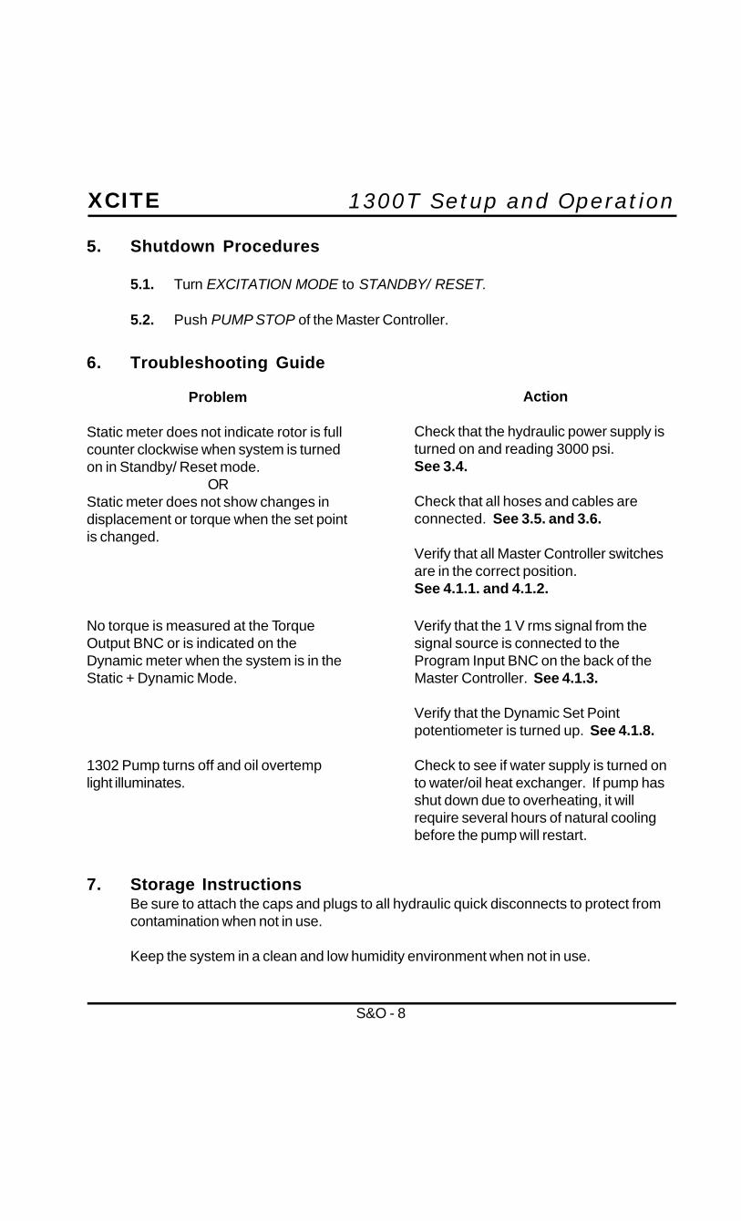
5.1. Turn EXCITATION MODE to STANDBY/ RESET.
5.2. Push PUMP STOP of the Master Controller.
7. Storage InstructionsBe sure to attach the caps and plugs to all hydraulic quick disconnects to protect fromcontamination when not in use.
Keep the system in a clean and low humidity environment when not in use.
Problem
Static meter does not indicate rotor is fullcounter clockwise when system is turnedon in Standby/ Reset mode.
ORStatic meter does not show changes indisplacement or torque when the set pointis changed.
Action
Check that the hydraulic power supply isturned on and reading 3000 psi.See 3.4.
Check that all hoses and cables areconnected. See 3.5. and 3.6.
Verify that all Master Controller switchesare in the correct position.See 4.1.1. and 4.1.2.
6. Troubleshooting Guide
No torque is measured at the TorqueOutput BNC or is indicated on theDynamic meter when the system is in theStatic + Dynamic Mode.
1302 Pump turns off and oil overtemplight illuminates.
Verify that the 1 V rms signal from thesignal source is connected to theProgram Input BNC on the back of theMaster Controller. See 4.1.3.
Verify that the Dynamic Set Pointpotentiometer is turned up. See 4.1.8.
Check to see if water supply is turned onto water/oil heat exchanger. If pump hasshut down due to overheating, it willrequire several hours of natural coolingbefore the pump will restart.

1300T Exciter Heads

1300T Exciter HeadsXCITE
EH - 1
1. IntroductionThe Xcite Torsional Exciter Head is a high torque rotary actuator capable of a widerange of static and sinusiodally varying dynamic torques (see specifications).
Incorporation of the latest design concepts in torque transducers and servo-valvesresult in a compact Exciter Head that is ideally suited to simulate the level and directionof input torques encountered in complex machinery. The Load Cell permits continuousreadout of static and dynamic torques. The Exciter Head is equipped with allnecessary hydraulic and electrical connectors. System design is such that it isimpossible to connect hydraulic or electrical connectors incorrectly. The Exciter Headis designed for use in industrial environments and, as such, is extremely rugged.
2. General DescriptionThe Exciter Head is comprised of three major components; a limited rotation rotaryactuator, a servo-valve and a torque transducer. A brief description of each individualcomponent follows:
2.1. Rotary ActuatorThe rotary actuator is essentially a limited rotation hydraulic motor permittingangular displacements of +/- 50 degrees. Oil is routed to the actuator through amanifold mounted on top. This system is designed for torsional loading only.Axial forces can severely damage the actuator.
2.2. Servo-ValveThe servo-valve is a double stage device with electromagnetic control in the firststage and the 3000PSI hydraulic pressure used for power amplification in thesecond stage. The device uses differential pressure to control the actuator.
2.3. Torque TransducerThe torque transducer is a specially designed load cell which exhibits theelectrical characteristics of a four-arm bridge. This bridge has a 350 ohmnominal resistance which changes linearly with torque. The supply voltage forthe bridge comes from the Master Controller.
Bridge calibration is accomplished by simulating bridge unbalance with thecalibration resistor supplied with the torque cell and adjusting the MasterController as described in the Master Controller section of this manual. Acalibration certificate for the transducer is included on all Heads supplied withtorque cells.

1300T Exciter HeadsXCITE
EH - 2
3. Specifications
Model 1307-15-Tor 1314-15-Tor 1318-15-Tor
Static Torque 20,000 in-lb(2,225 N-m) 2,000 in-lb(222 N-m) 6,000 in-lb (666 N-m)Dynamic Torque 20,000 in-lb(2,225 N-m) 2,000 in-lb (222 N-m) 6,000 in-lb (666 N-m)Stroke 100 deg (1.75 rad) 100 deg (1.75 rad) 100 deg (1.75 rad)Torque Cell 50,000 in-lb(5,550 N-m) 5,000 in-lb(555 N-m) 15,000 in-lb(1,660 N-m)Torque Cell Sensitivity 5,000 in-lb/v (555 N-m/v) 500 in-lb/v (55 N-m/v) 2000 in-lb/v (222 N-m/v)RVDT 100 deg (1.75 rad) 100 deg (1.75 rad) 100 deg (1.75 rad)RVDT Sensitivity 10 deg/v (.175 rad/v) 10 deg/v (.175 rad/v) 10 deg/v (.175 rad/v)Exciter Design 2 Vane Torsional 2 Vane Torsional 2 Vane Torsional
4. Head Operating InstructionsAll operations of the Exciter Head are controlled by the appropriate Xcite Controller.Please refer to the Master Controller section for proper use of system.
4.1. Rotation ConventionThe rotary actuators used in all three Torsional Exciter Systems adhere to the followingrotation convention:
When SW310 STATIC PRELOAD is set to COMPRESSION/CCW mode the actuatorrotates as follows:
4.1.1. For Angular Displacement ControlThe actuator rotates clockwise (CW) when viewed from the rear of the actuator(the end without the Torque Cell)
4.1.2. For Torque ControlThe actuator rotates clockwise (CW) when viewed from the rear of the actuatorand produces positive voltage torque readings in the CW position.
5. Theory of OperationThe major function of the Exciter Head is to apply static torque preload and/ or acontrolled sinusoidally varying dynamic torque (variable frequency) to a test specimen.The actuator shaft is the actual output device. The torque transducer, displacementtransducer (optional), and servo-valve provide the control on this output. The torque cellprovides an output signal proportional to static loads, but unlike a peizo-electrictransducer, has no charge leak-off. The cell is therefore well-suited to provide aconstant monitor of the exciter’s preload for use in the control circuitry. The torque cellprovides a signal proportional to time varying torque (dynamic) and thus providescomplete signal information on the output force.

1300T Exciter HeadsXCITE
EH - 3
6. MaintenanceExciter Head maintenance is minimal. Precautions for cleanliness are the majorconsiderations. End caps should always be kept on the Exciter Head hoses when theyare not connected. If any problems are encountered with any of the head components,the manufacturer should be contacted.
7. Drawings
7.1. Outline Dimensions for 1307, 1314 and 1318 Heads
The servo-valve is supplied a constant source of pressure (3000PSI) to apply to eitherside of the exciter vanes in a differential manner. The driving signal to the servo-valve isprovided by the system controller.
5.1. Electric Circuit DescriptionThe torque cell, displacement transducer and servo-valve are separatelyconnected to their respective cable connectors. Shielded cable is usedthroughout to provide optimum reduction of externally induced noise voltage.
5.2. Hydraulic Circuit DescriptionOil is supplied to the Exciter Head at 3000PSI by the Hydraulic Power Supply.The servo-valve controls the flow of this oil into the actuator ports, creating adifferential pressure according to the torques demands of the control system. Oil from the servo-valve is routed back to the hydraulic supply.
3.25 82.6 8.50 215 15.50 394 2.50 63.5 5.50 127.7 6.50 163 3.50 88.9 0.33 8.3 0.41 10.4
4.62 117.3 9.69 242 15.81 395 3.38 85.8 7.50 190.5 9.00 225 4.25 107.9 0.39 9.9 0.53 13.4
6.12 155.4 12.38 314 23.50 597 4.61 117.3 10.12 257.0 12.00 305 4.25 107.9 0.39 9.9 0.78 19.8
A B C D E F G H I
1318-15-Tor
1307-15-Tor
1314-15-Tor
ExciterHead in mm in mm in mm in mm in mm in mm in mm in (dia) mm (dia) in (dia) mm (dia)

1300T Exciter HeadsXCITE
EH - 4
7.2. Torque Cell Certificate of Calibration
7.3. Displacement (Radians) vs. Frequency of 1307-15-TOR Head
7.4. Torque (in-lbs) vs. Frequency of 1307-15-TOR Head
7.5. Master Controller Output Sensitivities (1307-15-TOR Only)Torque Cell: 5000 in-lb/ Volt and 555 N-m/ VoltDisplacement Transducer: 0.175 Rad/ Volt
1300T Exciter HeadsXCITE
EH - 5
Xcite 1300T-2 Torsional System - 1314-15-TOR Exciter Head
Xcite 1300T-3 Torsional System - 1318-15-TOR Exciter Head
Frequency (Hz)
Peak
Dis
plac
emen
t (ra
d)
1 10 100 1000
.001
.01
.1
.0001
1
10001
Peak
Dyn
amic
Tor
que (
in-lb
)
Frequency (Hz)10 100
10
100
1,000
10,000
100,000
Peak Displacement vs. Frequency
Frequency (Hz)
Peak
Dis
plac
emen
t (ra
d)
1 10 100 1000
.001
.01
.1
.0001
1
Peak Dynamic Torque vs. Frequency
10001
Peak
Dyn
amic
Tor
que (
in-lb
)
Frequency (Hz)10 100
1
10
100
1000
10,000
Peak Displacement vs. Frequency
Frequency (Hz)
Peak
Dis
plac
emen
t (ra
d)
1 10 100 1000
.001
.01
.1
.0001
1
Structure Stiffness:
Peak Dynamic Torque vs. Frequency
10001
Peak
Dyn
amic
Tor
que (
in-lb
)
Frequency (Hz)10 100
10
100
1000
10,000
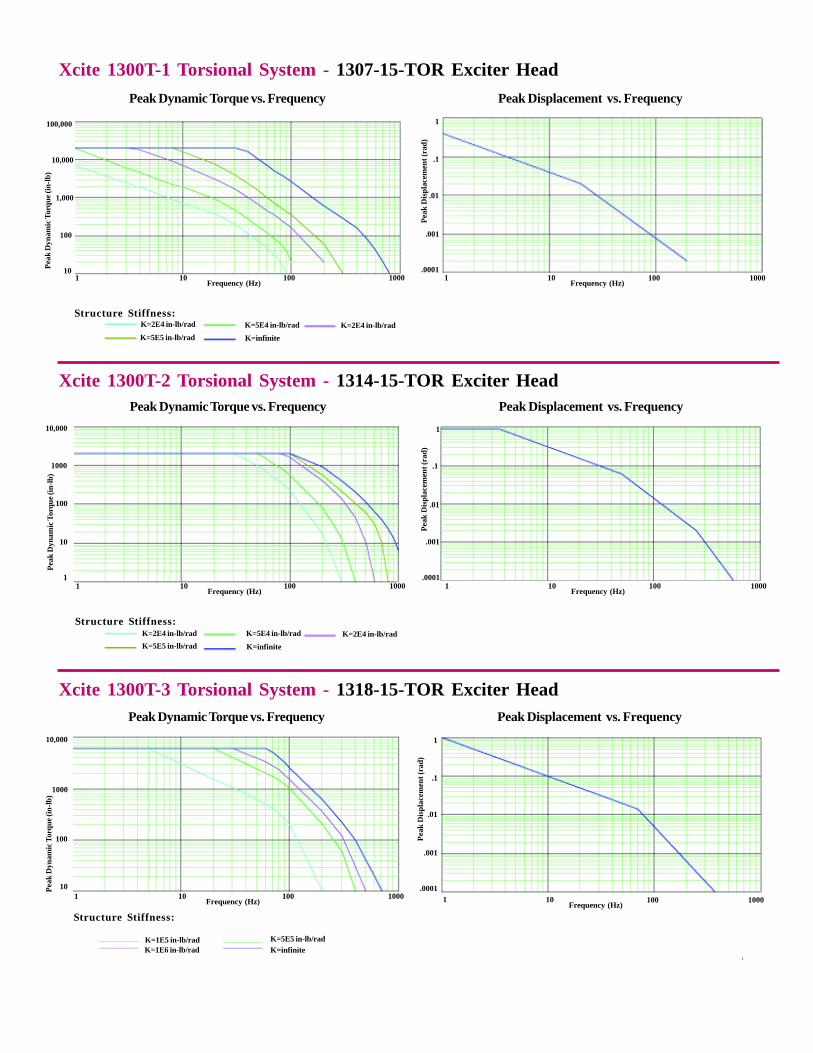
K=2E4 in-lb/rad K=5E4 in-lb/rad K=2E4 in-lb/radK=5E5 in-lb/rad K=infinite
Structure Stiffness:
K=2E4 in-lb/rad K=5E4 in-lb/rad K=2E4 in-lb/radK=5E5 in-lb/rad K=infinite
Xcite 1300T-1 Torsional System - 1307-15-TOR Exciter HeadPeak Displacement vs. FrequencyPeak Dynamic Torque vs. Frequency
K=1E6 in-lb/radK=1E5 in-lb/rad
Structure Stiffness:
K=5E5 in-lb/radK=infinite

1300T Exciter HeadsXCITE
EH - 6Xcite Systems Corporation • 675 Cincinnati Batavia Pike • Cincinnati, Ohio 45245Tel: (513) 528-7170 • Fax: (513) 528-7190 • Email: [email protected] • Web: www.xcitesystems.com

1302C Hydraulic Power Supply

1302C Hydraulic Power SupplyXCITE
1302CHPS - 1
1. IntroductionThe XCITE Hydraulic Power Supplies are designed to fulfill the power requirementsof exciter heads using the most energy-efficient and maintenance free componentsavailable. All units use a highly reliable, variable volume, pressure compensated,axial-piston pump to deliver only the energy demanded by the load, thus reducingpower consumption.
2. Theory of OperationThe purpose of the XCITE Hydraulic Power Supply is to supply clean hydraulic oilat a constant pressure under the varying flow demands of the force exciter head.The system was designed to do this is the most efficient manner, considering powerrequirements, reliability, safety, ease of maintenance, and operator convenience.
2.1. Circuit Description (Hydraulic) - See Drawing B-30066An oil reservoir provides storage for all necessary supply oil and providessome oil cooling. Mounted on the reservoir are oil level and oil temperaturegauges, a temperature sensitive switch, and a reservoir fluid level detectorswitch for motor shut down. A 3000PSI pressure is achieved by a variablevolume, pressure-compensated pump that has a factory set delivery rate.
Fluid from the pump first passes through a five-micron (absolute) filter. Shouldthis filter become clogged, a pressure drop builds up across the sensor, causinga switch to trip. This causes the FILTER light to illuminate. The system shouldnot be operated until the filter element is changed. After passing through thefilter, oil flows to the pressure output disconnect.
2.2. Circuit Description (Electric) - See Drawing B-30068The electrical input is specified at the time of purchase as either 200-230 or380-460 volt, 50/60 Hz, three phase. The fourth wire (green) is a ground wireand must be tied to earth ground to prevent floating grounds due to anunbalanced load.
The pump motor uses the high voltage three-phase power, while theremaining loads derive 120 volt, single-phase from the step-downTransformer T-1 (designated 5), appropriately connected to the incomingpower to provide 120 VAC on the secondary of the transformer.
Two-way protection of the three-phase power is provided. A magneticcircuit protector provides over current protection. It is also connected to theelectrical box operating handle to disconnect power in the electrical box.

1302C Hydraulic Power SupplyXCITE
1302CHPS - 2
Pump motor overload protection is provided by thermal overload heaters in themotor starter, which were specifically designed for the pump motor. A RESETbutton is conveniently located inside the electrical box, should be thermal over-load trip. The pump start relay (1CR), (designated 09), is a latch-up design sothat momentary switches may be used for pump start and pump stop operations.
A phase sequence relay 1PM (designated 04) is connected to and monitors the3-phase incoming line to determine if the phasing is connected correctly toprovide proper motor rotation. If the PHASE CORRECT light is off, any twolegs of the incoming lines should be reversed.
If the phase is incorrect, 1PM (04) remains de-energized, thus preventing thesystem from being energized. If the phasing is correct, 1PM (04) energizes,allowing 120 VAC from T-1 (05) to be applied to the pump unit.
The T-1(05) Transformer is fused by 4FU and 5FU (designated 21). The systemPOWER switch connects power to the control circuits. If oil temperature isnormal, relay 2CR (designated 09) is not energized. Momentarily, pressing theSTART button will energize 1CR (designated 09) if oil level, temperature, filter,and pressure selection are correct.
Relay 1CR (09) energizes the motor starter 02. Auxiliary contact 1M closes,latching 1CR. A normally closed CR1(09) contact opens, turning off the STOP light.
Momentarily pressing the STOP button breaks the latch-up circuit and de-energize 1CR (09) and the pressure relief solenoid. After a short delay, an OFFDELAY contact on 1CR opens, de-energizing the motor-starter coil andcausing the pump to stop.
Relay 3CR (designated 09) is normally not energized unless the oil level drops.If the RED OIL LEVEL LOW light illuminates, the system must be reset bypushing the pump STOP BUTTON on the Master Controller and oil must beadded to the reservoir. When a low oil level is detected, the pump is turned off.
Relay 2CR (09) is normally not energized unless the oil temperature exceeds140 degrees F. If the RED OIL OVERTEMP light is illuminated, the systemmust be reset by pushing the pump STOP BUTTON on the Master Controllerafter the system cools down.
If the differential pressure drop across the filter exceeds approximately 50PSI,the RED FILTER restriction light will illuminate, the Power Supply will NOT shutoff, however the filter should be changed when the filter light is illuminated.

1302C Hydraulic Power SupplyXCITE
1302CHPS - 3
3. DescriptionIncluded with the hydraulic power supply are an oil supply line pressure gauge and atimer which records actual pump running time. Mounted on the side of the reservoir isan oil level sight gauge with an integral oil temperature thermometer. A reservoir drainis also located on the reservoir. All motor controls and associated electrical equipmentare located in the electrical control box. Connections for pressure and return hoses areattached with quick disconnect style connectors.
3.1. Major Components Oil Reservoir Motor Variable volume pressure-compensated Pump Five-micron Filter Assembly Water Heat Exchanger Motor Control Box Hydraulic Hoses
3.2. Control Components
3.2.1. Emergency Stop SwitchThis switch de-energizes the motor-starter relay, bypassing allshutdown logic; thus causing the motor to stop. Use it only inan emergency situation.
Some operating conditions cause the system to shutdown.
3.3. Monitoring Devices
3.3.1. Phase Sequence Relay (PHASE Indicator)A phase sequence relay monitors the three-phase powerapplied to the unit. If the phasing of the wires is incorrect, therelay will prevent the pump from being energized, and the PHASECORRECT lamp will NOT illuminate.
3.3.2. Filter Pressure Drop Sensor (FILTER Indicator)This sensor sends a signal if the differential pressure across thefilter element is excessive. This occurs when the differentialpressure drop across the replaceable filter element exceeds50PSI. Excessive differential pressure occurs when the filterelement is clogging, fluid viscosity is too high, fluid temperature istoo low, or any combination. At that time, the FILTER lightilluminates and the filter should be replaced.
WARNING

1302C Hydraulic Power SupplyXCITE
1302CHPS - 4
Note: There may be times when the system is first started and theoil is cold that the filter light will illuminate. Allow 10 to 20 minutesof operation and if the filter light goes off, then the filter is not dirtyand does not need replaced.
3.3.3. OIL OVERTEMP IndicatorThe temperature sensor monitors the oil temperature of thereservoir and prevents the pump from running if the oil temperatureexceeds 140degrees F. The OIL OVERTEMP light illuminates,indicating that the maximum allowable oil temperature has beenexceeded.
3.3.4. LOW OIL IndicatorThe level sensor monitors the oil level in the oil reservoir andprevents the pump from running if the oil level is low. The pumpwill shut down or fail to start until additional oil is added. Thered LOW OIL indicator lamp illuminates during this condition.
4. Care and Maintenance
Electrocution or severe electrical shock may occur.
When the MAIN power is plugged in, the line side of themotor starter is at line voltage.
The XCITE Hydraulic Power Supply was designed so that no periodiclubrication on mechanical parts is required. Cleanliness is very importantwhen using sophisticated hydraulic systems, and although a clean roomenvironment is far from necessary, general cleanliness is recommended.Routine maintenance on the overall system should include the following.
4.1. Operating Care
4.1.1. Wipe off all cables after each use.
4.1.2. Never drag cables across the floor.
4.1.3. Immediately after the hydraulic hoses are disconnected, cover allhydraulic connectors with the covers provided.
WARNING

1302C Hydraulic Power SupplyXCITE
1302CHPS - 5
4.1.4. During operation, the oil temperature should never rise above145 degrees F. (The oil temperature thermal relay shuts down thesystem at 150 degrees F.)
4.1.5. Before each test, check the oil pressure to make sure it is at3000PSI. A flow screw adjustment is located on the top of thepump compensator assembly. This control is preset at the factoryand should not be adjusted (knob with locknut).
4.1.6. Before each test, check to make sure that the water supply isturned on and the supply water temperature is below 70 degrees F,that the pump maintenance warning lights are not illuminated, andthat the phase sequence indicator shows proper motor phasing.
If for some reason the system has overloaded, the pump motorstarted thermal overload will trip. Reset it by opening theaccess door, and pushing the reset button located on the motorstarter.
4.2. Maintenance
4.2.1. To keep the system operating within the specified limits, it isnecessary to periodically check the oil level by observing theoil level gauge. Fluid should fill the gauge.
4.2.2. Oil should be changed after every 1000 hours of pumpoperation.
4.2.3. The condition of the filter is displayed by the light on theelectrical control box inside the cabinet. The filter requiresreplacement only when the FILTER light is illuminated.
4.2.4. Oil should be drained from the reservoir during transportation.
5. TroubleshootingListed below are some of the common problems which may be experienced with aPower Supply.

1302C Hydraulic Power SupplyXCITE
1302CHPS - 6
5.1. Unit Overheats causing Pump To Turn Off and Oil Overtemp To IlluminateOverheating may be caused by an interuption in water flow to the water/oil heatexchanger or supply water temperatures above 70 degrees F. Check to see thatwater is flowing through the water/oil heat exchanger at 8GPM when the oiltemperature is above 135 degrees F. If pump has shut down due to overheating,it will require several hours of natural cooling before the pump will restart.
5.2. Pump de-energizesA pump de-energizes for no apparent reason can be caused by a noisy3-phase power line at which the 3-phase voltage drops below 220 VAC(60 Hz) for more than 10 milliseconds. This results in the phase monitor relay1PM momentarily de-energizing, shutting off the system.
6. SpecificationsItem Specifications
Dimensions Height Width DepthWeight
Hydraulic OilFilter 5 MicronPumpPressure-compensatedvariable flow axial piston
Motor, 220, 3-Phase, 60 Hz
ReservoirCooling
Noise Level (at 3 feet with full pump flow at 3000PSI)
60”36”48”1500 lb (without oil)
Mobil DTE-24
15 GPM
30 HP
40 gallonWater (50 PSI, 70 degrees F,8GPM Flow)
81 to 88 dBA depending onlocation
7. DrawingsModel 1302C-220Outline Dimensions B-30065Hydraulic Schematic B-30066Electrical Schematic 220 VAC, 60 Hz B-30068Electrical Box Layout B-30067


1100, 1200 and 1300 Master Controller
Master ControllerXCITE
MC - 1
1. IntroductionThe Xcite Master Controller is a compact electronics control package designed toprovide all the controls and displays necessary to operate an Xcite exciter system.The latest concepts in electronic design, including plug-in printed circuit boards, flexiblesystems interface and easy-to-use operator controls, are incorporated in the unit.
The Master Controller represents the heart of the closed loop hydraulic exciter system.It enables two variables to be independently controlled simultaneously via the StaticLevel and Dynamic Level controls. It incorporates automatic gain control in the dynamicloop which allows a constant amplitude of the dynamic variable to be maintained evenas the reference frequency of excitation is changed.
2. Theory of OperationThe major design concept used in the Xcite Master Controller is one of providingaccurate feedback control of an exciter head’s capability, such as force, displacement,velocity, acceleration, etc.
The Master Controller senses the feedback signals from the appropriate transducersand provides an output drive signal to the exciter head servovalve which will cause theexciter to maintain the desired levels of the static and dynamic variable as determinedby the dynamic and static level controls.
2.1. ConfigurationsThe master controller can be operated in either a single- or dual-loopconfiguration.
2.1.1. Single LoopSingle-loop operation is selected by placing the Frequency Rangeswitch to the LOW position. This mode is generally used to control asingle variable, usually force or displacement. In this LOWFREQUENCY mode of operation, a dynamic signal is generated bysumming the reference frequency present at the PROGRAM INPUTwith the Static Level set point signal.
2.1.2. Dual LoopDual-loop operation is selected by placing the FREQUENCYRANGE switch to the HIGH position. This mode applies the dynamicfeedback signal to the dynamic control loop which incorporates anautomatic gain control circuit. This allows a desired dynamicamplitude variable to be set and maintained over a broad frequencyrange and structure stiffnesses.

Master ControllerXCITE
MC - 2
3. DescriptionThe Xcite Master Controller (Model 1104, 1204 and 1304) has a variety of inputs andswitch selectors which allows the various operational modes of the Exciter Head. Listedbelow is a description of each connector, switch and indicator located on the MasterController.
MASTERCONTROLLER
STATIC SIGNAL LEVEL
DITHER
ON
OFF
STATICSETPOINT
VARIABLE
FIXED
STATIC GAIN LOAD CELL POWER PUMP
EXCITATION MODE
STANDBY/RESET
STATIC
STATIC + DYNAMIC
OUTPUT
ZEROOPERATE
CALIBRATE-ADJ.
SW-304 L301INTERLOCK
START STOP
DYNAMIC SIGNAL LEVEL
DYNAMICSETPOINT
FREQUENCY
HIGH
LOW
Front Panel
SW308 R301 SW305 R307 J301 R302 SW307 R306 SW301 SW302 SW303 R303 SW309
M-101 M-102
EXCITER HEADJ305
INTERLOCKJ306
POWERJ307
FUSEF301
MASTER CONTROLLER REAR PANEL (OUTSIDE VIEW)
Outside Rear Panel
PROGRAMINPUT
J308
DISPLACEMENTJ311
CALIBRATIONRESISTOR
J304
CONTROLLED VARIABLE
INPUT INPUT
STATIC DYNAMIC
INTERNAL(FORCE)
EXTERNALJ309
R311CAL
R304CAL
J302
SW311 SW306
STATIC PRELOAD
COMPRESSION/ CCW
TENSION/ CWSW310
COMPRESSIONOUTPUT
LOAD CELLOUTPUT
STANDBYLEVEL
J310 J303
POWERAMP
R313 SW312
INT
EXT
INPUTJ312
S/NFUSE DESIGNATION
115 VAC/3 AMP230 VAC/1.5 AMP
60/60 HZ
EXT SET POINT
STATIC
DYNAMIC
J313
J314
(HIGH FREQ)
XCITE SYSTEMS CORPMILFORD, OHIOMADE IN USA
OFF

Master ControllerXCITE
MC - 3
3.1. Front Panel (Left and Right Top Section)
3.1.1. Static Signal Level Meter (M-101)The Static Signal Level is displayed on this meter in Static ForcePounds or Static Displacement.
3.1.2. Static Set Point (R301)Potentiometer used to set value of desired static variable. The StaticSet Point potentiometer is calibrated in percent full scale.
3.1.3. Dynamic Signal Level Meter (M-102)The Dynamic Signal Level is displayed on this meter in Peak DynamicForce Pounds.
3.1.4. Dynamic Set Point (R303)Potentiometer used to set value of desired dynamic variable. TheDynamic Set Point potentiometer is calibrated in Peak DynamicForce Pounds.
3.1.5. Excitation Mode (SW304)
Used to select operating mode of exciter head. Turn the switch so thatthe arrow points to the mode of interest.
EXCITATION MODE
STANDBY/RESET
SW304
STATIC
STATIC + DYNAMIC
INTERLOCK
L301
STATIC SIGNAL LEVEL DYNAMIC SIGNAL LEVEL
M-101 M-102
STATICSETPOINT
R301
DYNAMICSETPOINT
R303

Master ControllerXCITE
MC - 4
Standby/ ResetExciter head is at (or returns to) standby position, as preset byset-screw potentiometer on rear of Master Controller. The interlockcircuits are also reset in this mode.
StaticOnly the static control loop is activated.
Static + DynamicThe static and dynamic control loops are activated.
3.1.6. Interlock Selector Switch (Optional) and Light 301The Interlock Selector Switch (provided only on Master Controllersoperating torsional Exciter Heads) located directly below the redInterlock Light is used to disable the Interlock system when in theSTATIC MODE position. Normal Interlock occurs when the switch isin the UP position. Disabled Interlock occurs when the switch is in theDOWN position.
The Interlock Light indicates when interlock circuits are activated,causing exciter head to return to standby position. Excitation modecontrol switch must be moved to Reset position to continue operation.
3.1.7. Dither - ON/ OFF (SW308)
Toggle switch which, when in ON position, provides 400 Hz signal toexciter servovalve. It is used primarily to overcome exciter stiction atlow frequencies of operation. (Below 5 Hz)
3.1.8. Static Set Point (R301)Indicates desired static level. Calibrated in percent full scale. See 3.1.2.
3.1.9. Static Gain
Static Gain - Variable/ Fixed (SW305)Toggle switch. In VARIABLE position actuates loop static gainpotentiometer (R307).
DITHER
ON
OFF
STATICSETPOINT
SW308 R301
VARIABLE
FIXED
SW305
STATIC GAIN
R307
Front Panel (Left) - Bottom Section
Master ControllerXCITE
MC - 5
Static Gain (R307)Potentiometer used to set static control loop gain based on thestiffness of the structure under test. Used to eliminate control loopinstabilities when using exciter in Static Displacement Mode on aweak structure.
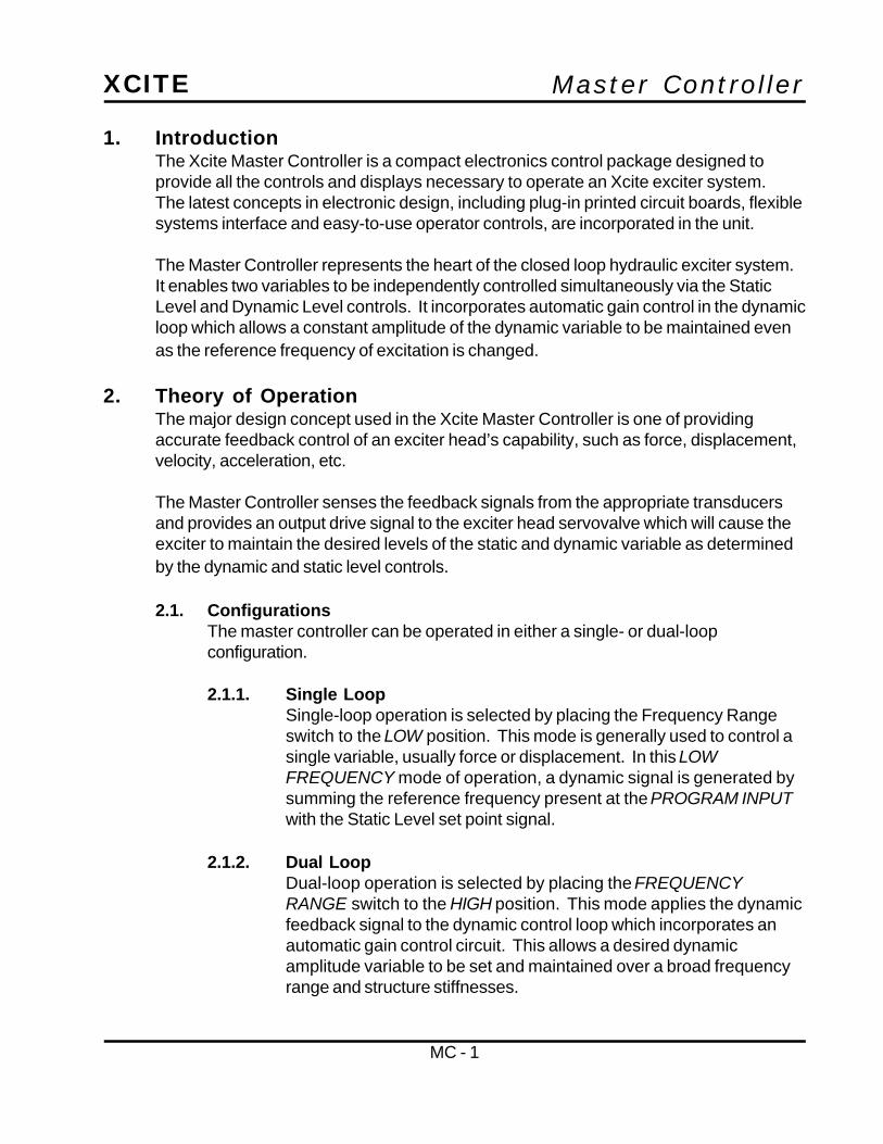
3.1.10. Load Cell
Output (J301)BNC connector providing load cell output signal for monitoring of theforce signal (varies from -10V to +10V depending on the actual valueof the force). Duplicated on back of controller.
Zero (R302)Set screw potentiometer used to zero the load cell output when thereis no load applied.
3.1.11. Calibrate/ Operate (SW307)
Adj. (R306)Set screw potentiometer used to adjust the master controller for thecalibration value of the load cell when (SW307) is in the calibratemode. (See load cell calibration plug for calibration value).
OperateSelect the operate mode of load cell once calibration is complete.
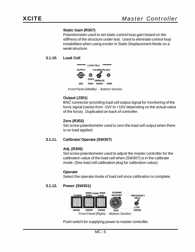
3.1.12. Power (SW301)
Push switch for supplying power to master controller.
Front Panel (Middle) - Bottom Section
OPERATEJ301
LOAD CELL
OUTPUT
ZERO
CALIBRATE-ADJ.
R302 SW307 R306
PUMPPOWER START STOP
DYNAMICSETPOINT FREQUENCY
HIGH
LOWSW301 SW302 SW303 SW309R303
Front Panel (Right) - Bottom Section

Master ControllerXCITE
MC - 6
3.1.13. Pump
Start (SW302)Push switch with internal red indicator light to energize power supply.
Stop (SW303)Push switch to de-energize hydraulic power supply.
3.1.14. Dynamic Set Point (R303)Indicates desired peak dynamic level. Calibrated in engineeringunits. See 3.1.4.
3.1.15. Frequency Range - HIGH/ LOW (SW309)HIGH - Compressor control of dynamic signal at 5 Hz and above.LOW - Single loop control of force or displacement.
3.2. Rear Panel
3.2.1. Exciter Head (J305)Input connection for servovalve and load cell cable from exciter head.
3.2.2. Displacement (J311)Input connection for displacement transducer cable from exciter head.
3.2.3. Calibration Resistor (J304)Jack input for calibration plug provided with Load Cell Transducer.
3.2.4. Static Preload (SW310)Dual-position switch establishes sign convention of static preload.When exciter head is operated by “pushing” on the test article, thisswitch should be in the COMPRESSION position. If exciter head isoperated by “pulling” on the test structure, this switch should be in theTENSION position.
Rear Panel - Top Section
EXCITERHEADJ305
DISPLACEMENT
J311
CALIBRATIONRESISTOR
J304
STATIC PRELOAD
SW310
COMPRESSION/CCW
TENSION/CW

Master ControllerXCITE
MC - 7
3.2.5. Interlock (J306)Input connect for interlock function. If external control of thisfunction is not desired, an Xcite supplied mating connector with pinsC and D shorted must be used. If user supplied external control isdesired, then appropriate contact closure between pins C and D mustbe supplied. Pins A and B are supplied for interlock of additionalexternal equipment, as required.
3.2.6. Power (J307)Input connection for cable from hydraulic power supply. When anon-Xcite hydraulic power supply is used, this is the input connectionfor the direct 110V AC power cord.
3.2.7. Fuse (F301)Use 3 amp fuse for 115 VAC. Use 1.5 amp fuse for 230 VAC.
3.2.8. Program Input (J308)Input connection for signal from reference oscillator.
Rear Panel (Left) - Bottom Section
INTERLOCKJ306
POWERJ307
FUSEF301
PROGRAMINPUT
J308
A 1 volt RMS signal must be provided toensure system control calibration.
Master ControllerXCITE
MC - 8
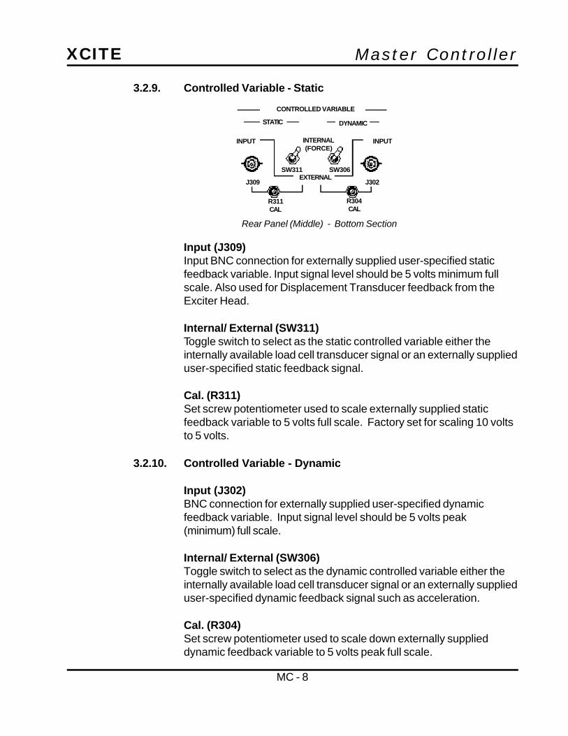
3.2.9. Controlled Variable - Static
Input (J309)Input BNC connection for externally supplied user-specified staticfeedback variable. Input signal level should be 5 volts minimum fullscale. Also used for Displacement Transducer feedback from theExciter Head.
Internal/ External (SW311)Toggle switch to select as the static controlled variable either theinternally available load cell transducer signal or an externally supplieduser-specified static feedback signal.
Cal. (R311)Set screw potentiometer used to scale externally supplied staticfeedback variable to 5 volts full scale. Factory set for scaling 10 voltsto 5 volts.
3.2.10. Controlled Variable - Dynamic
Input (J302)BNC connection for externally supplied user-specified dynamicfeedback variable. Input signal level should be 5 volts peak(minimum) full scale.
Internal/ External (SW306)Toggle switch to select as the dynamic controlled variable either theinternally available load cell transducer signal or an externally supplieduser-specified dynamic feedback signal such as acceleration.
Cal. (R304)Set screw potentiometer used to scale down externally supplieddynamic feedback variable to 5 volts peak full scale.
CONTROLLED VARIABLE
Rear Panel (Middle) - Bottom Section
STATIC DYNAMIC
INPUT INPUTINTERNAL(FORCE)
EXTERNAL
R311CAL
R304CAL
J302J309
SW311 SW306

Master ControllerXCITE
MC - 9
3.2.11. Compression Output (J310)BNC connection providing an output signal which is proportionalto dynamic forward control signal (servovalve drive signal) aftermultiplication by reference oscillator signal.
3.2.12. Standby Level (R313)Set screw potentiometer determining static level when MasterController is in standby or interlock mode.
3.2.13. Load Cell Output (J303)BNC connector providing load cell output signal for monitoring of theforce signal (+/- 10V max). Duplicated on front of controller.
3.2.14. Power Amp - INT/ EXT (SW312)Toggle switch to select input signal to power amplifier. INTERNALposition is used for normal operation and provides dynamic controlsignal proportional to level requested on the front of the MasterController at the reference oscillator frequency. EXTERNAL positionis used for external dynamic control applications such as random orshaped random signals from an FFT Analyzer or random noisegenerator. In EXTERNAL position, the DYNAMIC SET POINT(R303) potentiometer on the front panel attenuates the externaldynamic control signal and the DYNAMIC SIGNAL LEVEL METER(M-102) indicates 1.41 times the true RMS voltage of the dynamicvariable feedback level.
3.2.15. Power Amp - INPUT (J312)BNC connector used to supply external control signal source withPOWER AMP toggle switch on EXTERNAL. Use only J308PROGRAM INPUT with toggle switch on INTERNAL.
Rear Panel (Left) - Bottom Section
COMPRESSIONOUTPUT
LOAD CELLOUTPUT
J303
POWERAMP
INT
EXT
INPUT
SW312
J312
R313
J310
STANDBYLEVEL
Master ControllerXCITE
MC - 10
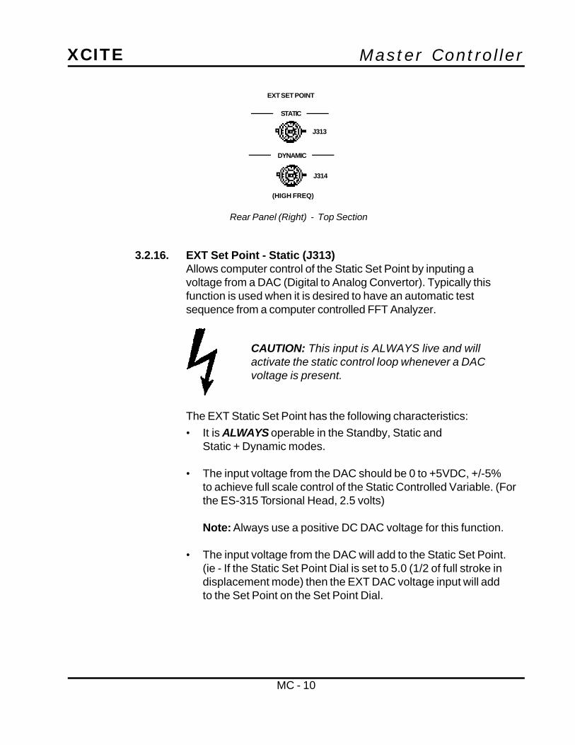
3.2.16. EXT Set Point - Static (J313)Allows computer control of the Static Set Point by inputing avoltage from a DAC (Digital to Analog Convertor). Typically thisfunction is used when it is desired to have an automatic testsequence from a computer controlled FFT Analyzer.
The EXT Static Set Point has the following characteristics:
• It is ALWAYS operable in the Standby, Static andStatic + Dynamic modes.
• The input voltage from the DAC should be 0 to +5VDC, +/-5%to achieve full scale control of the Static Controlled Variable. (Forthe ES-315 Torsional Head, 2.5 volts)
Note: Always use a positive DC DAC voltage for this function.
• The input voltage from the DAC will add to the Static Set Point.(ie - If the Static Set Point Dial is set to 5.0 (1/2 of full stroke indisplacement mode) then the EXT DAC voltage input will addto the Set Point on the Set Point Dial.
EXT SET POINT
STATIC
DYNAMIC
J313
J314
(HIGH FREQ)
CAUTION: This input is ALWAYS live and willactivate the static control loop whenever a DACvoltage is present.
Rear Panel (Right) - Top Section

Master ControllerXCITE
MC - 11
3.2.17. EXT Set Point - Dynamic (J314)Allows computer control of the Dynamic Set Point by inputing avoltage (NOT frequency) from a DAC (Digital to Analog Convertor).Typically this function is used when it is desired to have an automatictest sequence from a computer controlled FFT Analyzer.
The EXT Dynamic Set Point has the following characteristics:
• It operates in the Static + Dynamic Mode.
• It only operates in the High Frequency Range
Note: Never use in the Low Frequency Range Mode
• The input voltage from the DAC should be 0 to -5VDC, +/-10%to achieve full scale control of the Dynamic Controlled Variable.
Note: Always use a negative DC DAC voltage for this function.
• The input voltage from the DAC will add to the Dynamic SetPoint. (ie - If the Dynamic Set Point Dial is set to 5.0, then theEXT DAC voltage input will add to the Set Point value. In thisexample a DAC voltage of -2.5V will make the Set Point 100%).
4. Operation
4.1. Concept of OperationThe Xcite Master Controller is designed so that the variables to be controlledcan be readily selected by the positions of the Controlled Variable switcheslocated on the rear panel of the controller.
When the Controlled Variable switches are in the Internal position, the controlledvariable will be force. The force feedback signal is internally routed to the staticand dynamic control loops. The composite force signal is separated by a low-pass and high-pass filter, with the DC and AC levels of the composite signalbeing displayed by the Static and Dynamic meters, respectively.
CAUTION: This input is live when the ModeControl Switch is in the Static + Dynamic Mode.Dynamic Force output will occur whenever a DACvoltage is present at this input.

Master ControllerXCITE
MC - 12
If a variable(s) other than force is to be controlled, the Controlled Variableswitches can be placed in the External position and feedback from the variableto be controlled can be applied to the External Static and/ or External Dynamicinputs. This allows alternate variables such as displacement to be statically anddynamically controlled, or two variables such as static displacement anddynamic force to be controlled.
4.2. System InterconnectionMount the exciter head to be operated securely in its test configuration andconnect the hydraulic pump hoses to the exciter.
4.2.1. Exciter head cable (J305 to servovalve and load cell)
4.2.2. Displacement kit cable (J311 to exciter displacement kit)
4.2.3. Power cord or pump cable (J307 to J501 or 110 VAC)
4.2.4. Reference oscillator to Program input J308 (1 V RMS +/- 50 MV)
4.2.5. Connect an oscilloscope and/ or D.V.M. to Load Cell outputs J301or J303.
4.3. Operation - Force ControlTo operate the exciter under force control, place the following switches andcontrols in the positions given.
4.3.1. Set Controls
MODE CONTROL STANDBY/RESETDITHER OFFLOOP GAIN FIXED (If test specimen
static stiffness is less than10,000 lbs/inch, place invariable & set variable gaincontrol at 5.00)
FREQUENCY RANGE HIGHSTATIC SET POINT 0DYNAMIC SET POINT 0STATIC CONTROLLED VARIABLE INTERNALDYNAMIC CONTROLLED VARIABLE INTERNALTENSION/ COMPRESSION COMPRESSION

Master ControllerXCITE
MC - 13
4.3.2. Depress the Power switchThe controller will energize and a momentary deflection of themeter pointers may occur.
4.3.3. Adjust Load Cell
•• Adjust the load cell zero adjust for 0 Volts on a digital voltmeter. Refer to the Calibration plug located on the rear of thecontroller for the load cell calibrate value and the outputsensitivity of the controller.
•• Place the load cell calibrate switch in the calibrate position. Ifnecessary, adjust the load cell calibrate screw until the voltagemeasured by the digital volt meter equals the calibration voltage. The calibration voltage equals the calibration valuedivided by the output sensitivity.
Example:Cal. Value = 742 lbsOutput Sens. = 250 lbs/ vtherefore: 742/250 = 2.968v at J301/ J303
•• Return the load cell calibrate switch to the operate position.
4.3.4. Depress Pump Start ButtonThe Hydraulic Power Supply should energize.
•• Set the Mode Control switch to the Static position.
•• Slowly turn the Static Set Point clockwise until the requiredstatic force is obtained, as indicated on the Static Meter. Ifoperating into a “weak” structure, static force instability mayoccur. If this should happen, adjust the Variable loop gaincounterclockwise until static stability is achieved.
•• Set the reference oscillator to the desired excitation frequency.
•• Set the Mode Control switch to Static + Dynamic position.
•• Turn the Dynamic Set Point clockwise until the desired dynamicforce is obtained.

Master ControllerXCITE
MC - 14
Note: Refer to the Exciter Head specifications for maximum peakforce versus frequency.
•• If swept sine test are to be run, the sweep rate of the oscillator willhave to be adjusted so that the dynamic level does not decreaseas the frequency is swept upward. If this occurs, lower the sweeprate until the dynamic level is maintained as the oscillatorfrequency is swept.
4.4. Operation - Displacement ControlIf the exciter head is to be operated under displacement control, place thecontroller switches in the following positions.
4.4.1. Set ControlsMODE CONTROL STANDBY/RESETDITHER OFFLOOP GAIN VARIABLE (Variable loop
gain control at 5.00)
FREQUENCY RANGE LOWSTATIC LEVEL 0DYNAMIC LEVEL 0STATIC CONTROLLED VARIABLE EXTERNALDYNAMIC CONTROLLED VARIABLE INTERNALTENSION/ COMPRESSION COMPRESSION
• Energize the controller and the hydraulic power supply.• Switch the Mode Control to the Static position.• Turn the Static Set Point potentiometer until the desired static
position is reached. The static position can be read on the StaticMeter in percent of full stroke. For instance, if the exciter headbeing used has a 1 inch stroke and the Static meter reads 40%,then the exciter piston is extended 40% of one inch or .4 inch.
The exciter piston position can be dynamically varied by turning theMode Control switch to the Static + Dynamic position and adjustingthe Dynamic Level control for the desired stroke. The Dynamic meterwill not indicate the peak displacement in this mode of operation. Itwill be necessary to monitor the displacement signal at the ExternalStatic Variable input jack J309. The input signal at this point will be0 - 10 VDC. If the exciter has a 1 inch stroke, then full stroke will beequal to 10 VDC. On torsional exciters, 10 VDC represents 100degrees of rotation.

Master ControllerXCITE
MC - 15
If compressor control is desired, the Frequency Range should be setto the High position and the displacement input also connected to theDynamic External Static input J302. At frequencies belowapproximately 5 Hz full stroke of the exciter may not be obtained in theHigh Frequency mode. However, the amplitude of the 1 V RMS signalfrom the reference oscillator may be increased to obtain a slightlylarger dynamic stroke.
4.5. Operation - External VariableOperation using the External Static and Dynamic controlled variable inputs isvery similar to the operation using the internal controlled variable. Onerequirement, however, is that the external variables be scaled to the full scalevalue of the Static and Dynamic meters. This is accomplished by adjusting theExternal Cal. potentiometers. A 5 VDC signal is required for full scale deflectionof the Static meter and a 5 V peak signal is required for full scale deflection ofthe Dynamic meter. The Static External Cal. potentiometer is factory adjustedfor 10 VDC full scale static signal. The Dynamic Cal. potentiometer is adjustedfor a 5 V peak dynamic signal. If signals larger than these are to be used, theCal. potentiometer should be readjusted so that those signals will cause fullscale deflection of the meters.
4.6. Computer Control - External Set Points (Static and Dynamic)As explained in Section 3.2.16. and Section 3.2.17., it is possible to have acomputer controlled FFT Analyzer control the Static and Dynamic Set Points ofthe Master Controller. Separate DAC output voltages are required for the StaticSet Point and Dynamic Set Points. The Static DAC output must be a positivevoltage and the Dynamic DAC output must be a negative voltage.
When using an external computer to input the Static and Dynamic Set Points,attention must be paid to the consequences of inputing a DAC voltage when theHydraulic Power Supply is turned on. The Exciter Head will attempt to operatewhen these signals are present even with the Mode Control Switch in Standby.STRUCTURE DAMAGE OR PERSONAL INJURY CAN OCCUR IF THETEST SEQUENCE IS NOT THOROUGHLY PLANNED.

Master ControllerXCITE
MC - 16
5. Theory of OperationThe Xcite Master Controller consists of seven major circuits. They are:
• Static control circuitry• Dynamic control circuitry• Power amplifier• Load cell amplifier• Displacement transducer buffer/ amplifier• Interlock circuitry• Pump/ start/ stop
Each section is described in detail as follows.
5.1. Circuit DescriptionsRefer to the Master Controller block diagram and to the appropriate printedcircuit board schematics for the following circuit descriptions.
5.1.1. VR101 (Voltage Regulator)Provides the excitation voltage for the load cell. The regulated voltageis determined by the values of R169 and R170.
To calibrate the load cell, place a precision shunt resistance (Cal.Plug provided with each load cell) into J304 and place the load cellcalibrate/ operate switch SW307 in the calibrate position. Thiscauses an imbalance of the load cell bridge and results in an output ofthe load cell amplifier A109. The excitation voltage to the load cell isthen varied by adjusting R306 until the output of A109 corresponds tothe calibration value of the load cell, as given on the calibration plug.
5.1.2. SW310 (Preload Switch)Allows the outputs of the load cell to be reversed before being appliedto A109. This will cause the exciter head to operate in a tensionmode, instead of a compression mode.
5.1.3. A109 (Amplifier)A109 is a precision differential instrumentation amplifier used toamplify the differential voltages from the load cell bridge. R166 andA108 allow the output of A109 to be scaled to a convenientengineering unit for monitoring purposes. The output of A108 isavailable at BNC jacks on the front and rear of the Master Controller.
V out = 1.25V(1 + R170)R169

Master ControllerXCITE
MC - 17
The output of A109 is also applied to SW311 and SW306. Whenthese switches are in the INTERNAL position, the force signal isapplied to the static and dynamic loops as the feedback signaland controlled variable.
5.1.4. A104 and A105 (Static Control Loop)The static control loop consists of A105 and A104. A105 is a dualop-amp. A105B is a low-pass filter which allows the static portion ofthe feedback signal to be indicated by the static meter. A105A is aninverter/ buffer stage. R137 allows calibration of the dynamic levelcontrol when operating in the LOW FREQUENCY force control. R135allows calibration in the LOW FREQUENCY displacement control.
The feedback signal from A105A is summed with the static levelsignal at the summing junction of A104. A104 is a low-pass filterwhich provides high DC gain which rolls off at 6DB/ octave at abreakpoint determined by R174 and C108. R176, R102 and R113determine the DC gain of A104. The output of A104 is appliedthrough SW311 and / or K201 and to the appropriate feedback pathas determined by the controlled variable.
The output of A104 is also applied to R133 and enables the staticloop gain to be adjusted for optimum operation of the exciter headunder force control. Further operator adjustment of the static loopgain is provided by R307 when the GAIN switch SW305 is in theVARIABLE position.
5.1.5. A401 and A402 (Dynamic Loop)The dynamic loop has two main circuits. One circuit, consisting ofA401 and A402, demodulates the incoming reference frequency andconverts it to a DC reference signal which is applied to the DynamicLevel Control, R303.
The dynamic demodulator circuit consist of a low-pass filter A103,and a true RMS-to-DC converter, U102. The DC portion of the forcesignal is blocked by C109. The output of U102 is a DC signal. ThisDC is summed with the dynamic set point signal from the wiper ofR303. The resultant error signal is integrated by A012 and C104. ThisDC error signal is applied to one input of the four-quadrant multiplier,U101. The reference frequency supplied by the reference oscillator issupplied to the other input of U101. The output of U101 is a signal with

Master ControllerXCITE
MC - 18
a frequency identical to the reference frequency and with an amplitudeequal to the product of the two input signals. A101A converts thecurrent output of U101 to a voltage. A101B provides output offsetcapabilities. C101 and C102 allow the dynamic signal to have twobreakpoints at higher frequencies, as required to prevent theservovalve drive signal from clipping.
The output of U101 and A104 are applied to summing amplifier A201.The dither signal is also summed at this point if it is selected by thedither switch. The output of A202 is a composite error signal which isthen applied to the power amplifier.
The power amplifier is a voltage-to-current converter circuit. Theoutput current will remain constant for a given input voltage, eventhough the load impedance (servovalve coils) changes.
5.1.6. A107 (Inverter Buffer)This circuit allows the displacement transducer to be offset andscaled to convenient engineering units. The scaled displacementsignal is fed out through J311/ G into a BNC cable which is thenconnected to J309. By placing the Static controlled variable switch inthe External position, displacement will become the static controlledvariable.
5.1.7. A106 and U103 (Peak Detector Circuit)A106 and U103 form a peak detector circuit which can be adjusted ifan absolute value of displacement is exceeded. It is primarily usedwith inertial mass exciter heads, and only appears in MasterControllers with the MOD2 option.
The interlock circuitry provides a means of insuring that the systemsalways power up to a preset level, determined by Standby level pot. Ifpower is applied to the Master Controller with the Mode Controlswitch in either the Static or Static + Dynamic position, the system willinterlock. The Mode Control switch must then be placed in theStandby/ Reset position. The Hydraulic Power Supply must also beenergized before proceeding to the desired mode of operation.

Master ControllerXCITE
MC - 19
6. SpecificationsModes:• Standby/ Reset Continuously variable standby level• Static Continuously variable static level• Static + Dynamic Continuously variable static level and
dynamic level• External Static Input 10 K ohms input impedance
Positive polarity 0 - 10V• External Dynamic Input 10 K ohms input impedance
10 V peak AC• Dither 400 Hz +/- 10%• Control Accuracy 40 dB of full scale controlled variable• Program Input Reference Signal 1.0 VAC RMS +/- 50 MV - sinusoidal
5.0 V peak maximum - random• Power Amp Input Reference Signal 0 to 5 Volt Peak• EXT Static Set Point 0 to +5VDC for full scale operation• EXT Dynamic Set Point 0 to -5VDC for full scale operation
7. DrawingsController Schematic D-015393Block Diagram Master Controller (2 sheets) D-015391Schematic PCB 110-01 Sheet 3 - Load Cell Amp & Peak-Detector C-015358Schematic PCB 110-01 Sheet 1 - Static Loop C-015358Schematic PCB 110-01 Sheet 2 - Dynamic Loop C-015358PCB 110-01 (Component Location) D-015384Schematic PCB 110-02 C-014893Assy PCB 110-02 (Component Location) C-014881Schematic PCB 110-04 C-010660Assy PCB 110-04 (Component Location) C-014882PCB110-05 Romass Schematic C-015528-3

Master ControllerXCITE
MC - 20

Master ControllerXCITE
MC - 21
8. Parts ListXcite reserves the right to substitute parts without notice.
Component Part Number Description
ChassisR301, 303, 307 1K, 10 Turn 5000 Series Pot
R302 50K, Trim Pot 3059J-1-503-M
R304, 311, 313 10K, Trim Pot 3059J-1-103-M
R305 Load Cell Dependent Phone Jack
R306 500 Ohm, Trim Pot 3059J-1-501-M
R308, 309, 310 47K, 1/2W, 5%
R312 110K, 1/4W, 5%
R314 100 Ohms, 1/4W, 5%
C301 50 MFD, 50V 7121L (39D)
T301, 302 Transformer, F-90X
T303 Supply, HAA-15-8
F301 Fuse, AGC 3, 3 amp
SW301 5A DPDT, 520-101G-51-A1H
SW302, 303 5A SPUT, 518-1016-51-A1H
SW304 Rotary 4P3T, 44A60-04-1-3N
SW305, 309, 311 4PDT Locking Toggle, MTL-406N
SW306, 312 DPDT Locking Toggle, MTL-206N
SW307, 308 SPDT Locking Toggle, MTL-106D
SW310 Rotary 5PDT, 71B30, 01-5-02N
M101, 102 100 Microamp, 4.5", 7045-3602-0000 API
J301, 302, 303 BNC Connector, UG-1094A/U
J304 Phone Jack, 12-B
J305 MS3102A-18-1S
J306 MS3102A-18-4S
J307 MS3102A-18-12P
J311 MS3102A-18-1P
KN301 Knob, DS70-2BD-2 (Rear)
KN302 Knob, DS70-3-2 (Front)
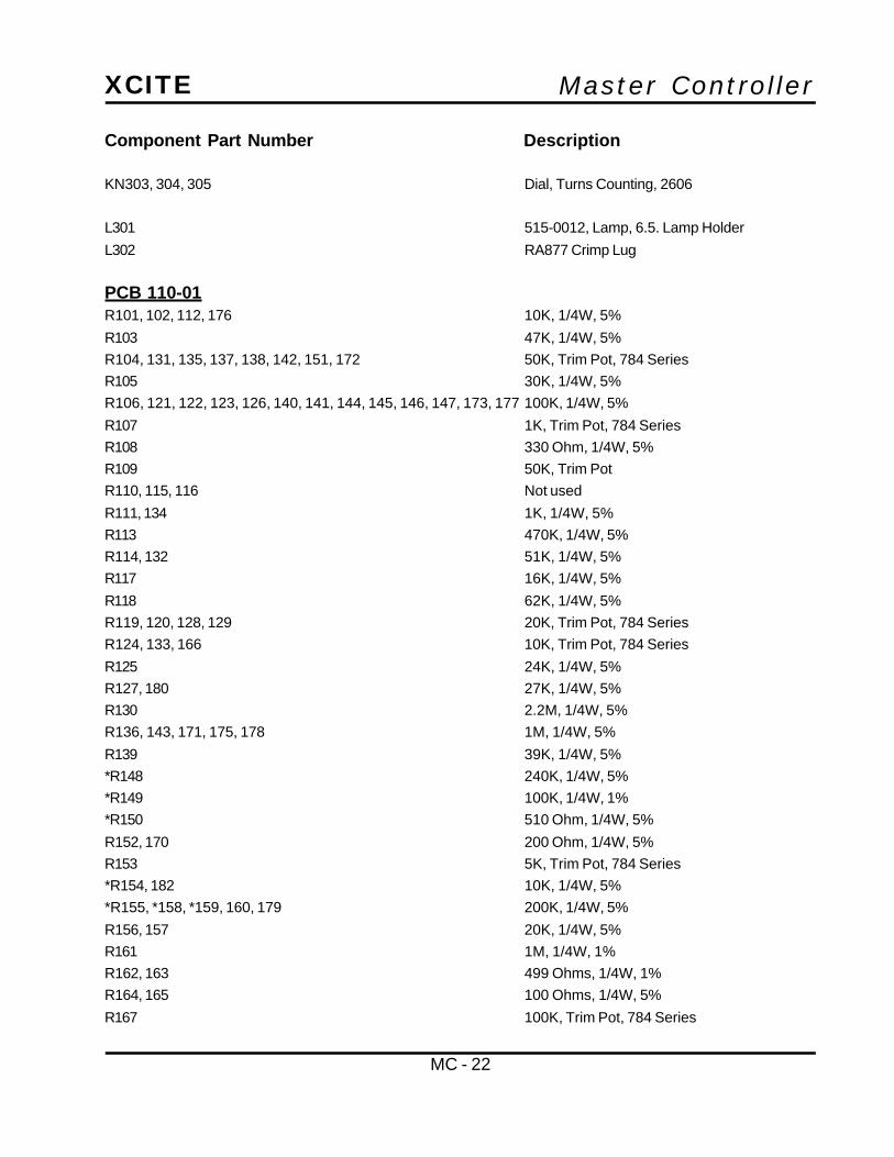
Master ControllerXCITE
MC - 22
KN303, 304, 305 Dial, Turns Counting, 2606
L301 515-0012, Lamp, 6.5. Lamp Holder
L302 RA877 Crimp Lug
PCB 110-01R101, 102, 112, 176 10K, 1/4W, 5%
R103 47K, 1/4W, 5%
R104, 131, 135, 137, 138, 142, 151, 172 50K, Trim Pot, 784 Series
R105 30K, 1/4W, 5%
R106, 121, 122, 123, 126, 140, 141, 144, 145, 146, 147, 173, 177 100K, 1/4W, 5%
R107 1K, Trim Pot, 784 Series
R108 330 Ohm, 1/4W, 5%
R109 50K, Trim Pot
R110, 115, 116 Not used
R111, 134 1K, 1/4W, 5%
R113 470K, 1/4W, 5%
R114, 132 51K, 1/4W, 5%
R117 16K, 1/4W, 5%
R118 62K, 1/4W, 5%
R119, 120, 128, 129 20K, Trim Pot, 784 Series
R124, 133, 166 10K, Trim Pot, 784 Series
R125 24K, 1/4W, 5%
R127, 180 27K, 1/4W, 5%
R130 2.2M, 1/4W, 5%
R136, 143, 171, 175, 178 1M, 1/4W, 5%
R139 39K, 1/4W, 5%
*R148 240K, 1/4W, 5%
*R149 100K, 1/4W, 1%
*R150 510 Ohm, 1/4W, 5%
R152, 170 200 Ohm, 1/4W, 5%
R153 5K, Trim Pot, 784 Series
*R154, 182 10K, 1/4W, 5%
*R155, *158, *159, 160, 179 200K, 1/4W, 5%
R156, 157 20K, 1/4W, 5%
R161 1M, 1/4W, 1%
R162, 163 499 Ohms, 1/4W, 1%
R164, 165 100 Ohms, 1/4W, 5%
R167 100K, Trim Pot, 784 Series
Component Part Number Description

Master ControllerXCITE
MC - 23
R168 953K, 1/4W, 1%
R169 2.2K, 1/4W, 5%
R174 1M, 1/4W, 5%, Mod 4, 100K, 1/4W, 5%, Mod 2
*R181 30K, 1/4W, 5%
*R182 10K, 1/4W, 5%
R183 22K, 1/4W, 5%
R184 100K, 1/4W, 5%
R185 147K, 1/4W, 5%
C101 .68 MF Mod 4, .068 MF Mod 2
C102 .001 MF, 160-.015-20-400-C
C103, 110 Not Used
C104, 111, 112, 113 10 MF, 20V Dipped Tant.
C105 15 MF, 20V Dipped Tant.
C106 4.7 MF, 20V Dipped Tant.
C107, 114 1 MF, 20V Dipped Tant.
C108 4.7 MF, 100V 160-4.7-20-100-H
(Mod 4 option only) (Not used for Mod 2)
C109 .68 MF, 100V 160-.68-20-100-D
C115 .0022 MF, 160-.0022-400-C
CR101, 102, 107 Not Used
CR103, *105, *106, *108 IN914
CR104 IN4737A
CR109
U101 MC1494L
U102 AD536AJD
*U103 MC14013B
VR101 LM317LZ
A101, 105, *106 MC1458CP1
A102, 108 MC1741CP
A103, 104, 107 LF13741N
A109 LM308AN
K101 SPST, 360-12-1A
*Q101 MPSA13
Component Part Number Description

Master ControllerXCITE
MC - 24
PCB 110-02R201, 202 47 Ohm, 1/2W, 5%
R203 Not Used
R204 20K, 1/4W, 5%
R205 470K, 1/4W, 5%
R206, 209 1K, 1/4W, 5%
R207, 219, 222, 225 10K, 1/4W, 5%
R208, 212, 216, 221, 224 100K, 1/4W, 5%
R210 220K, 1/4W, 5%
R211 10K, 2W, 5%
R213, 214 820 Ohm, 1/4W, 5%
R215, 223 Not Used
R217, 218 10 Ohm, 1/2W, 5%
R220 3.6K, 1/4W, 5%
R226 1K, Trim Pot, 784 Series
R227 10K, 1/4W, 5%
R250 Valve Dependent, 1/4W, 5%
C201, 202 50 MF, 75V TVA-1343
C203, 205, 207 Not Used
C204 .047 MF, 160-.015-400-C
C206 .01 MF, 160-.01-630-C
C208 .033 MF, 160-.033-250-C
CR201 thru 211 IN5059
A201, 202 LF356N
K201, 202 Relay, 4PDT 1315-4C-12VDC
Q201 2N697
Q202 2N4036
Q203 2N3440
Q204 2N3441
Q205 2N5632
Q206 2N6229
Component Part Number Description
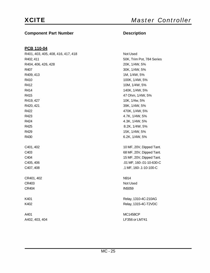
Master ControllerXCITE
MC - 25
PCB 110-04R401, 403, 405, 408, 416, 417, 418 Not Used
R402, 411 50K, Trim Pot, 784 Series
R404, 406, 426, 428 20K, 1/4W, 5%
R407 30K, 1/4W, 5%
R409, 413 1M, 1/4W, 5%
R410 100K, 1/4W, 5%
R412 10M, 1/4W, 5%
R414 140K, 1/4W, 5%
R415 47 Ohm, 1/4W, 5%
R419, 427 10K, 1/4w, 5%
R420, 421 39K, 1/4W, 5%
R422 470K, 1/4W, 5%
R423 4.7K, 1/4W, 5%
R424 4.3K, 1/4W, 5%
R425 8.2K, 1/4W, 5%
R429 15K, 1/4W, 5%
R430 6.2K, 1/4W, 5%
C401, 402 10 MF, 20V, Dipped Tant.
C403 68 MF, 20V, Dipped Tant.
C404 15 MF, 20V, Dipped Tant.
C405, 406 .01 MF, 160-.01-10-630-C
C407, 408 .1 MF, 160-.1-10-100-C
CR401, 402 N914
CR403 Not Used
CR404 IN5059
K401 Relay, 1310-4C-210AG
K402 Relay, 1315-4C-T2VDC
A401 MC1458CP
A402, 403, 404 LF356 or LM741
Component Part Number Description
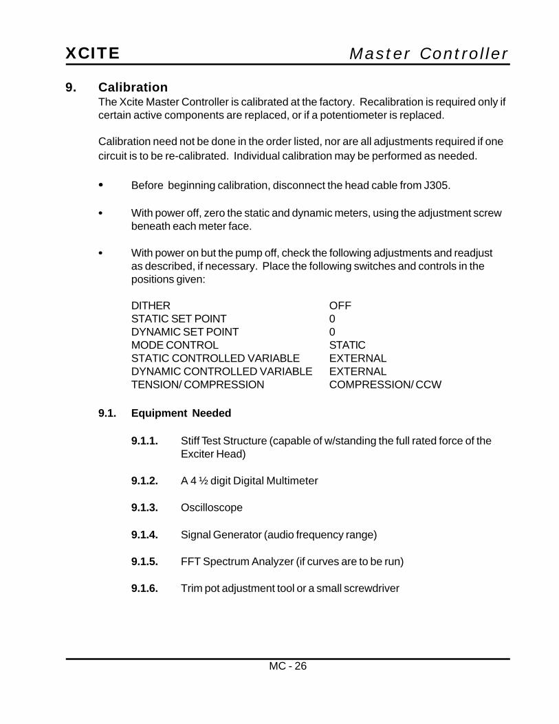
Master ControllerXCITE
MC - 26
9. CalibrationThe Xcite Master Controller is calibrated at the factory. Recalibration is required only ifcertain active components are replaced, or if a potentiometer is replaced.
Calibration need not be done in the order listed, nor are all adjustments required if onecircuit is to be re-calibrated. Individual calibration may be performed as needed.
•• Before beginning calibration, disconnect the head cable from J305.
•• With power off, zero the static and dynamic meters, using the adjustment screwbeneath each meter face.
•• With power on but the pump off, check the following adjustments and readjustas described, if necessary. Place the following switches and controls in thepositions given:
DITHER OFFSTATIC SET POINT 0DYNAMIC SET POINT 0MODE CONTROL STATICSTATIC CONTROLLED VARIABLE EXTERNALDYNAMIC CONTROLLED VARIABLE EXTERNALTENSION/ COMPRESSION COMPRESSION/ CCW
9.1. Equipment Needed
9.1.1. Stiff Test Structure (capable of w/standing the full rated force of theExciter Head)
9.1.2. A 4 ½ digit Digital Multimeter
9.1.3. Oscilloscope
9.1.4. Signal Generator (audio frequency range)
9.1.5. FFT Spectrum Analyzer (if curves are to be run)
9.1.6. Trim pot adjustment tool or a small screwdriver

Master ControllerXCITE
MC - 27
9.2. Master Controller
9.2.1. Meter Zero Adjustments
•• Turn the Master Controller off.•• The Static and Dynamic meters should be resting precisely
at zero.
•• If necessary, adjust the meters to zero using the small holescentered under each front panel meter.
•• Turn the Master Controller on.
9.2.2. +/-15 Volt Supply Check
•• Check for +15.00 Volts at 110-01-1 and -15.00 Volts at 110-01-3.•• If necessary adjust the supplies to within +/-10mV using the trim
pots located on the power supply (mounted to the left rear of thechassis).
15 VDC POWER SUPPLY
5 V POWER SUPPLY
PCB-110-05
PCB-110-04
PCB-110-02
PCB-110-01
T-302 TOPT-301 BOTTOM
PRINTED CIRCUIT BOARD LOCATION
STATIC SIGNAL LEVEL DYNAMIC SIGNAL LEVEL
M-101 M-102
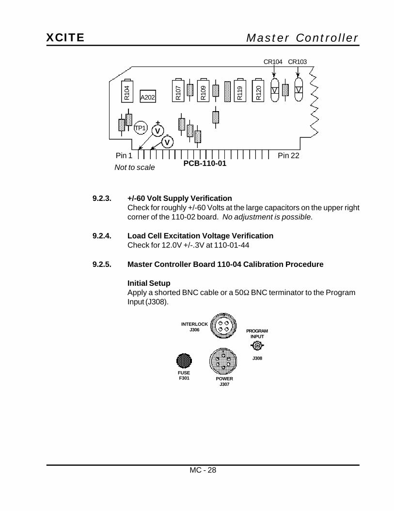
Master ControllerXCITE
MC - 28
9.2.3. +/-60 Volt Supply VerificationCheck for roughly +/-60 Volts at the large capacitors on the upper rightcorner of the 110-02 board. No adjustment is possible.
9.2.4. Load Cell Excitation Voltage VerificationCheck for 12.0V +/-.3V at 110-01-44
9.2.5. Master Controller Board 110-04 Calibration Procedure
Initial SetupApply a shorted BNC cable or a 50Ω BNC terminator to the ProgramInput (J308).
INTERLOCKJ306
POWERJ307
FUSEF301
PROGRAMINPUT
J308
+
-V
V
Pin 1 Pin 22PCB-110-01Not to scale
R10
4
R10
7
R10
9
R11
9
R12
0 V V
CR104 CR103
A202
TP1

Master ControllerXCITE
MC - 29
Program Input Offset AdjustmentAdjust R411 for 0mV at TP3.
Dynamic Reference Offset AdjustmentAdjust R402 for 0mV at TP2.
Pin 1PCB-110-04
Not to scale
R40
2
A401
Pin 22
R41
1
TP1 A402
A403
TP2
TP3
V
Pin 1PCB-110-04
Not to scale
R40
2
A401
Pin 22
R41
1
TP1 A402
A403
TP2
TP3
V

Master ControllerXCITE
MC - 30
Dynamic Reference AC to DC Level Verification
•• Apply 1.000V rms to the Program Input (J308).•• Check for roughly -10.8V DC at TP2.•• Remove signal from the Program Input (J308).
Dither Oscillator VerificationCheck for a 26V peak to peak, 360 Hz Triangle wave (+/-20 Hz) at TP4.
Pin 23PCB-110-04Not to scale
Pin 44
A404 TP4
V
INTERLOCKJ306
POWERJ307
FUSEF301
PROGRAMINPUT
J308
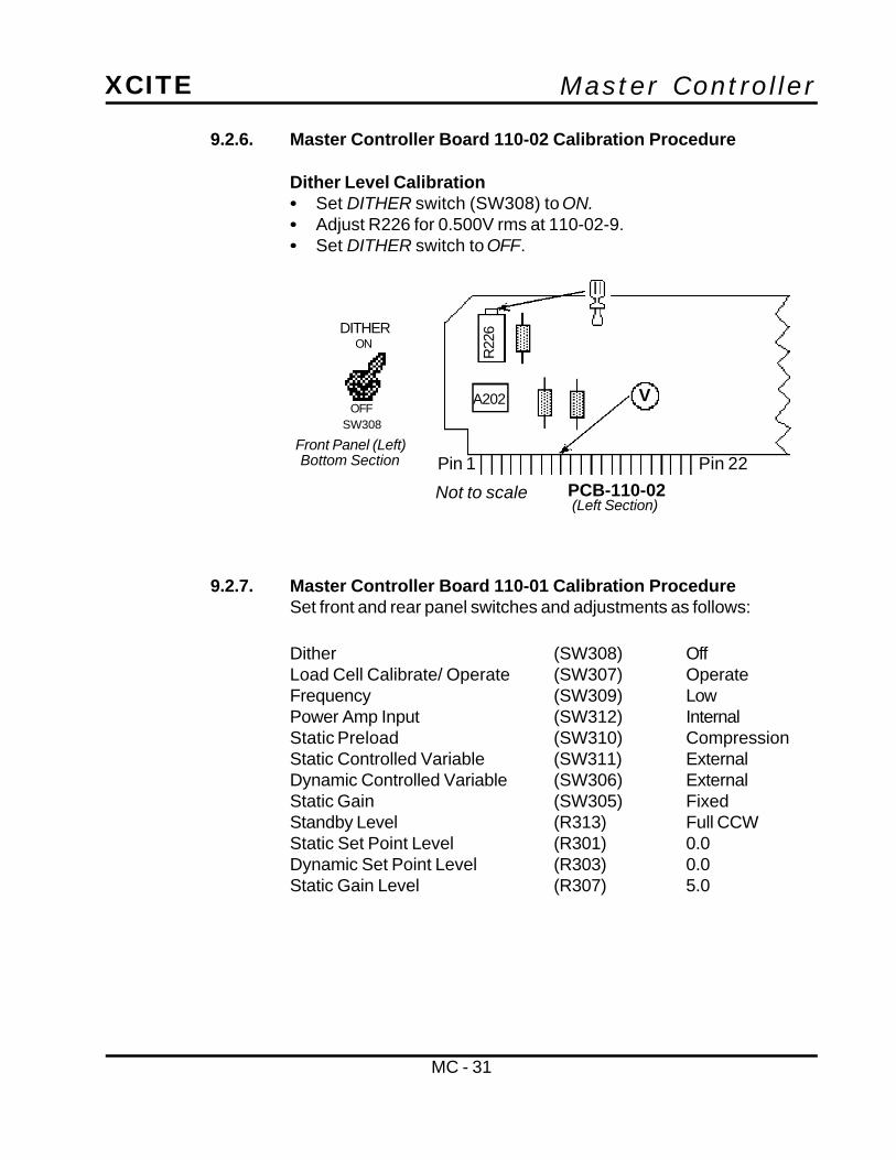
Master ControllerXCITE
MC - 31
9.2.6. Master Controller Board 110-02 Calibration Procedure
Dither Level Calibration•• Set DITHER switch (SW308) to ON.•• Adjust R226 for 0.500V rms at 110-02-9.•• Set DITHER switch to OFF.
9.2.7. Master Controller Board 110-01 Calibration ProcedureSet front and rear panel switches and adjustments as follows:
Dither (SW308) OffLoad Cell Calibrate/ Operate (SW307) OperateFrequency (SW309) LowPower Amp Input (SW312) InternalStatic Preload (SW310) CompressionStatic Controlled Variable (SW311) ExternalDynamic Controlled Variable (SW306) ExternalStatic Gain (SW305) FixedStandby Level (R313) Full CCWStatic Set Point Level (R301) 0.0Dynamic Set Point Level (R303) 0.0Static Gain Level (R307) 5.0
Front Panel (Left)Bottom Section
(Left Section)
ON
OFF
DITHER
Pin 1
PCB-110-02Not to scaleR
226
Pin 22
A202 V
SW308

Master ControllerXCITE
MC - 32
External Static and Dynamic Variable Input Calibration
• Apply a 1.000V rms, 100 Hz sine wave to the External StaticVariable Input (J309).
•• Adjust External Static Cal (R311) for .500V rms at 110-01-28(WHT/ RED wire).
•• Apply a 1.000V rms, 100 Hz sine wave to the External DynamicVariable Input (J302).
•• Adjust External Dynamic Cal (R304) for .500V rms at 110-01-25(WHT/ BLK wire).
•• Remove signal
Load Cell Amplifier Common Mode Null Adjustment
•• Apply a 1.000V rms, 100 Hz sine wave to 110-01-39 (BLK wire)and 110-01-41(SILVER wire).
•• Adjust R167 for minimum 100 Hz signal at TP9.•• Remove signal from 110-01-39 and 110-01-41.
Front Panel (Middle)
CONTROLLED VARIABLE
STATIC DYNAMIC
INPUT INPUTINTERNAL(FORCE)
EXTERNAL
R311CAL
R304CAL
J302J309
SW311 SW306
Pin 23PCB-110-01
Not to scale
Pin 44
V VSTATDYN
Twisted pair with a12” maximum length.
Pin 23PCB-110-01
Not to scale
R17
2
Pin 44
R16
6
R16
7TP8
TP7 A109TP9
A108V
A107

Master ControllerXCITE
MC - 33
Meter Amplifier Zero Offset AdjustmentsWith no signals applied, make the following settings:
Static Set Point Level (R301) 0.0Dynamic Set Point Level (R303) 0.0Static Controlled Variable (SW311) ExternalDynamic Controlled Variable (SW306) External
•• Adjust (Static Offset) R142 for 0mV at TP6.•• Adjust (Dynamic Offset) R131 for 0mV at TP3.
Static Meter Calibration
•• Apply 5.000V DC at 110-01-28 (WHT/ RED wire).•• Adjust R138 to set Static Meter deflection at 100%.•• Remove signal from 110-01-28.
PCB-110-01Not to scale
TP6 A105A104
A103
A102
TP5
TP3TP4
TP2
R14
2
R13
5
R13
3
R13
1
R12
9
R12
8
R13
7
R12
4
R13
8V
A105
R14
2
R13
8
Pin 23PCB-110-01
Not to scale
R17
2
Pin 44
R16
6
R16
7TP8
TP7 A109TP9
A108
V
A107

Master ControllerXCITE
MC - 34
Dynamic Meter Calibration
Pre RMS Converter Check•• Set the Dynamic Control Variable (SW306) to External.•• Apply a 100 Hz sine wave to the Dynamic Variable Input (J302).•• Adjust Signal level for 1.000V rms at 110-01-25 (WHT/ BLK wire).•• Check for an inverted 1.0V rms +/-5% signal at TP3.
RMS Converter CheckCheck for 1.00V DC at TP4.
Dynamic Meter Calibration Adjustment•• Adjust the signal level for 1.77V rms at 110-01-25 (WHT/ BLK wire).•• Adjust R129 for 50% full scale deflection of Dynamic Meter.•• Remove signal from Dynamic Variable Input (J302).
PCB-110-01Not to scale
TP6 A105A104
A103
A102
TP5
TP3TP4
TP2
R14
2
R13
5
R13
3
R13
1
R12
9
R12
8
R13
7
R12
4
R13
8
V V
Pin 23PCB-110-01
Not to scale
Pin 44
V
CONTROLLED VARIABLE
STATIC DYNAMIC
INPUT INPUT
EXTERNAL
R311CAL
R304CAL
J302J309
SW311 SW306
INTERNAL(FORCE)

Master ControllerXCITE
MC - 35
Dynamic Multiplier Calibration
Integrator Bias CalibrationAdjust R124 for -10mV DC at TP2.
P-Clip AdjustmentAdjust R109 fully clockwise (to Maximum).
Pin 1 Pin 22PCB-110-01Not to scale
R10
4
R10
7
R10
9
R11
9
R12
0 V V
CR104 CR103
A202
TP1
PCB-110-01Not to scale
TP6 A105A104
A103
A102
TP5
TP3TP4
TP2
R14
2
R13
5
R13
3
R13
1
R12
9
R12
8
R13
7
R12
4
R13
8
V

Master ControllerXCITE
MC - 36
Initial Multiplier Offset AdjustmentAdjust R104 for 0mV DC +/-100mV at TP1.
Multiplier X Input Null•• Apply a 1.0V rms, 120 Hz sine wave to the Cathode side of CR104.•• Adjust R119 for minimum 120 Hz signal at TP1.
Pin 1 Pin 22PCB-110-01Not to scale
R10
4
R10
7
R10
9
R11
9
R12
0 V V
CR104 CR103
A202
TP1
V
Pin 1 Pin 22PCB-110-01Not to scale
R10
4
R10
7
R10
9
R11
9
R12
0 V V
CR104 CR103
A202
TP1
V

Master ControllerXCITE
MC - 37
Multiplier Y Input Null•• Remove the signal from CR104.•• Apply a 1.0V rms, 120 Hz sine wave to the Program Input (J308).•• Adjust R120 for minimum 120 Hz signal at TP1.
Final Multiplier Offset Adjustment•• Remove signal generator.•• Adjust R104 for 0mV +/-10mV at TP1.
Pin 1 Pin 22PCB-110-01
R10
4
R10
7
R10
9
R11
9
R12
0 V V
CR104 CR103
A202
TP1
V
Pin 1 Pin 22PCB-110-01Not to scale
R10
4
R10
7
R10
9
R11
9
R12
0 V V
CR104 CR103
A202
TP1
V
INTERLOCKJ306
POWERJ307
FUSEF301
PROGRAMINPUT
J308
NOTE: Steps 2.4.7.4. and 2.4.7.5. may be slightly interactive.Repeat both adjustments until both inputs are nulled.

Master ControllerXCITE
MC - 38
9.3. Exciter Head Calibration ProcedureSet front and rear panel switches and adjustments as follows:
Dither (SW308) OffLoad Cell Calibrate/ Operate (SW307) OperateFrequency (SW309) LowPower Amp Input (SW312) InternalStatic Preload (SW310) CompressionStatic Controlled Variable (SW311) InternalDynamic Controlled Variable (SW306) InternalStatic Gain (SW305) VariableStandby Level (R313) Full CCWStatic Set Point Level (R301) 8.0Dynamic Set Point Level (R303) 5.0Static Gain Level (R307) 5.0
9.3.1. Load Cell Amplifier Calibration
Initial Setup•• Connect P305 end of the Controller Cable to J305 (Rear Panel).•• Connect the 4-pin cable to the load cell.•• Insert the Cal Plug into J304.
NOTE: The following two adjustments are very interactive; it willbe necessary to repeat both adjustments until an acceptablebalance is achieved.
EXCITERHEADJ305
DISPLACEMENT
J311
CALIBRATIONRESISTOR
J304
STATIC PRELOAD
SW310
COMPRESSION/CCW
TENSION/CW

Master ControllerXCITE
MC - 39
Adjust Load Cell Zero Calibration•• Set the Load Cell Operate/ Calibrate Switch (SW307) to OPERATE.•• Adjust the Load Cell Zero (R302) for 0mV at TP8 or LOAD CELL
outputs on Front or Rear Panel (J301 or J303).
Load Cell Meter Calibration
•• Set Load Cell Operate/ Calibrate Switch (SW307) to CALIBRATE.•• Adjust the Load Cell Calibration (R306) until the Static Meter
reads the Force value (expressed in lbs or Kg) that is supplied onthe Load Cell Cal Plug.
•• Repeat Load Cell Zero and Load Cell Meter Calibration untilcalibration and zero balance is achieved.
•• When finished leave the Load Cell Operate/ Calibrate Switch inthe OPERATE position.
OPERATE
J301
LOAD CELL
OUTPUT
ZERO
CALIBRATE-ADJ.
R302 SW307 R306
Pin 23PCB-110-01
Not to scale
R17
2
Pin 44
R16
6
R16
7TP8
TP7 A109TP9
A108V
A107
(Right)
OPERATE
J301
LOAD CELL
OUTPUT
ZERO
CALIBRATE-ADJ.
R302 SW307 R306
Front Panel (Middle)Bottom Section
OPERATE
J301
LOAD CELL
OUTPUT
ZERO
CALIBRATE-ADJ.
R302 SW307 R306

Master ControllerXCITE
MC - 40
Load Cell Amplifier ScalingAdjust R166 for Load Cell Calibration voltage at TP8 or LOAD CELLOUT using the following formula to determine values:
[Calibration Force (on Cal Plug)/Sens (on Cal Plug)]
Examples:[357lbs per 300Ω/ 250lbs per Volt]
= 1.428 Volts per 300 KΩ
9.3.2. Static Loop Gain CalibrationSet the front and rear panel switches and adjustments as follows:
Excitation Mode Switch (SW304) StandbyLoad Cell Calibrate/ Operate (SW307) OperateFrequency (SW309) LowStatic Preload (SW310) CompressionStatic Controlled Variable (SW311) InternalDynamic Controlled Variable (SW306) InternalStatic Gain (SW305) VariableStatic Set Point Level (R301) 8.0Dynamic Set Point Level (R303) 5.0Static Gain Level (R307) 5.0
2558 Kg1000 Kg/V
= 2.558V
Pin 23PCB-110-01
Not to scale
R17
2
Pin 44
R16
6
R16
7TP8
TP7 A109TP9
A108
V
A107
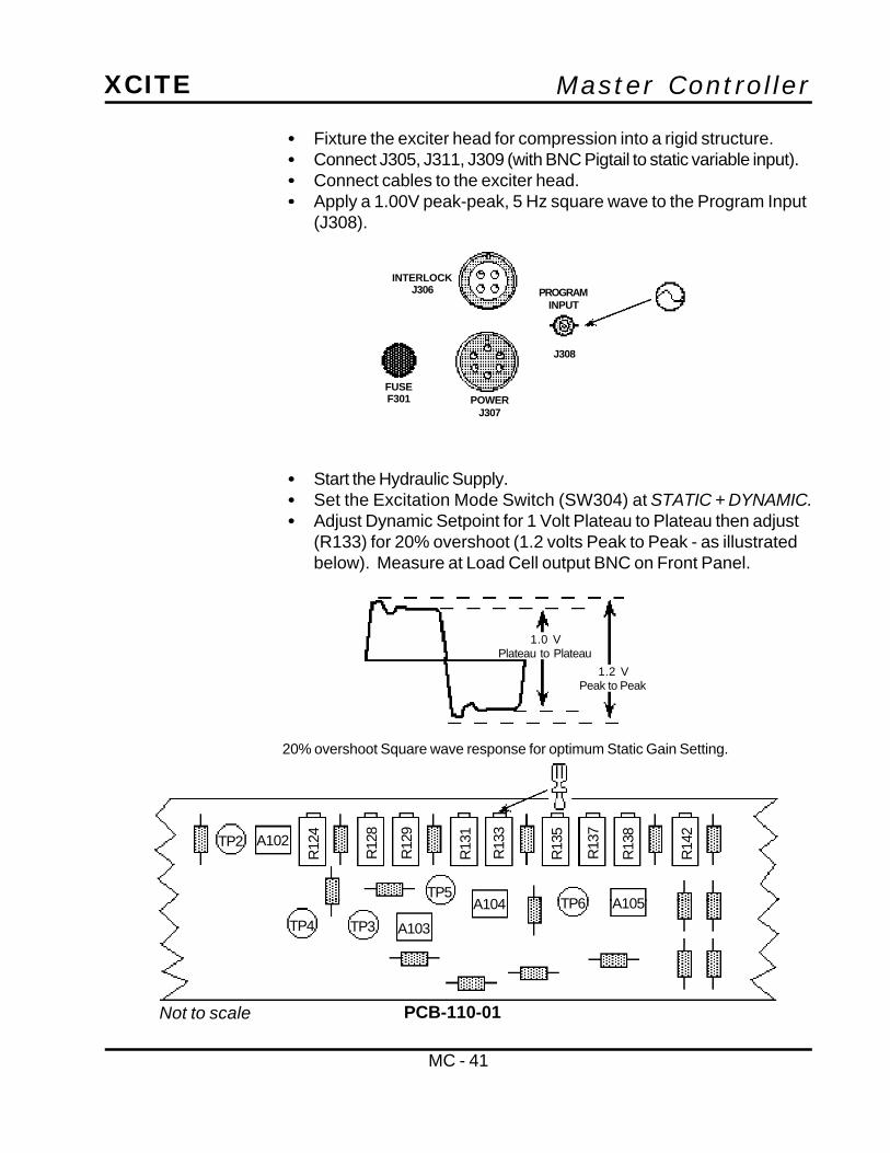
Master ControllerXCITE
MC - 41
•• Fixture the exciter head for compression into a rigid structure.•• Connect J305, J311, J309 (with BNC Pigtail to static variable input).•• Connect cables to the exciter head.•• Apply a 1.00V peak-peak, 5 Hz square wave to the Program Input
(J308).
•• Start the Hydraulic Supply.•• Set the Excitation Mode Switch (SW304) at STATIC + DYNAMIC.•• Adjust Dynamic Setpoint for 1 Volt Plateau to Plateau then adjust
(R133) for 20% overshoot (1.2 volts Peak to Peak - as illustratedbelow). Measure at Load Cell output BNC on Front Panel.
INTERLOCKJ306
POWERJ307
FUSEF301
PROGRAMINPUT
J308
1.0 VPlateau to Plateau
1.2 VPeak to Peak
20% overshoot Square wave response for optimum Static Gain Setting.
PCB-110-01Not to scale
TP6 A105A104
A103
A102
TP5
TP3TP4
TP2
R14
2
R13
5
R13
3
R13
1
R12
9
R12
8
R13
7
R12
4
R13
8

Master ControllerXCITE
MC - 42
9.3.3. Static Set Point Level CalibrationSet front and rear panel switches and adjustments as follows:
Excitation Mode Switch (SW304) StaticStatic Gain (SW305) FixedStatic Gain Level (R307) 5.0Static Set Point Level (R301) 5.0
• Adjust R107 (Static Cal) for a 50% Static Meter Reading.
9.3.4. High Frequency Dynamic Level CalibrationSet front and rear panel switches and adjustments as follows:
Load Cell Calibrate/ Operate (SW307) OperateFrequency (SW309) HighStatic Gain (SW305) FixedStatic Set Point Level (R301) 8.0Dynamic Set Point Level (R303) 5.0
•• Apply a 1.000V rms, 60 Hz sine wave to the Program Input (J308).•• Set the Excitation Mode Switch (SW304) to the
STATIC + DYNAMIC position.•• Adjust R128 for a 50% Dynamic Meter reading
(1.77V rms at 110-01-25).
Pin 1 Pin 22PCB-110-01Not to scale
R10
4
R10
7
R10
9
R11
9
R12
0 V V
CR104 CR103
A202
TP1

Master ControllerXCITE
MC - 43
9.3.5. Low Frequency Dynamic CalibrationSet front and rear panel switches and adjustments as follows:
Load Cell Calibrate/ Operate (SW307) OperateFrequency (SW309) LowStatic Gain (SW305) FixedStatic Set Point Level (R301) 8.0Dynamic Set Point Level (R303) 5.0
•• Apply a 1.000V rms, 10 Hz sine wave to the Program Input (J308).•• Set the Excitation Mode Switch (SW304) to the
STATIC + DYNAMIC position.•• Adjust R137 for a 50% Dynamic Meter reading
(1.77V rms at 110-01-25).
PCB-110-01Not to scale
TP6 A105A104
A103
A102
TP5
TP3TP4
TP2
R14
2
R13
5
R13
3
R13
1
R12
9
R12
8
R13
7
R12
4
R13
8
PCB-110-01Not to scale
TP6 A105A104
A103
A102
TP5
TP3TP4
TP2
R14
2
R13
5
R13
3
R13
1
R12
9
R12
8
R13
7
R12
4
R13
8

Master ControllerXCITE
MC - 44
9.4. Displacement Calibration ProcedureNote: Fixture Exciter head for full Stroke.
9.4.1. LVDT Symmetry Verification and AdjustmentSet front and rear panel switches and adjustments as follows:
Excitation Mode (SW304) Standby/ ResetLoad Cell Calibrate/ Operate (SW307) OperateFrequency (SW309) LowStatic Preload (SW310) CompressionStatic Controlled Variable(Disconnect DisplacementFeedback Signal for this set up) (SW311) ExternalStatic Gain (SW305) VariableStatic Set Point Level (R301) 10.0Static Gain Level (R307) 5.0
•• Set the Static Preload Switch (SW310) to TENSION (CW).The head should fully extend.
•• Set the Static Preload Switch to COMPRESSION (CCW).The head should fully retract.
•• While monitoring 110-01-38 (WHT/ YEL wire) with a DC voltmeter, you should observe a NEGATIVE voltage when the headis fully extended and a POSITIVE voltage when the head is retracted.These two voltages should be equal and opposite in magnitude.
NOTE: The importance is in the equality of thenumerical values not in their values. (i.e. +3 and -3are just as good as +6 and -6)
Pin 23PCB-110-01
Not to scaleR
172
Pin 44
R16
6
R16
7TP8
TP7 A109TP9
A108
V
A107
R15
3

Master ControllerXCITE
MC - 45
•• If the balance is off by more than 10%, the LVDT Rod or thepostion of the LVDT on the Exciter Head should be adjusted.
9.4.2. Displacement Zero Calibration
•• Set the Static Setpoint (R301) to 10.0.•• Set the Excitation Mode switch (SW304) to STATIC.•• Set the Static Preload switch (SW310) to TENSION.
The head should fully retract.•• Adjust R172 for 0mV at TP7.
9.4.3. Displacement Scaling Calibration
•• Set the STATIC PRELOAD SWITCH (SW310) toCOMPRESSION. The head should be fully extended.
•• Adjust R153 for 10.000V at TP7.•• The static meter should read 100% full scale deflection.•• Repeat steps 4.2. and 4.3. until balance is achieved.
9.4.4. Final External Static Control Variable Calibration
•• Verify 10.000V DC at TP7 (accurate to within 1.0mV)•• If necessary, adjust the Static Variable Cal (R311) for 0.5V
DC at 110-01-28
9.4.5. Dynamic Displacement CalibrationSet front and rear panel switches and adjustments as follows:
Frequency (SW309) LowPower Amp Input (SW312) InternalStatic Preload (SW310) CompressionStatic Controlled Variable (SW311) ExternalDynamic Controlled Variable (SW306) InternalStatic Gain (SW305) VariableStatic Set Point Level (R301) 5.0Dynamic Set Point Level (R303) 5.0Static Gain Level (R307) 5.0
Do not make mechanical adjustments to anexciter head while the hydraulic power supply is
active. Serious personal injury could result.
WARNING

Master ControllerXCITE
MC - 46
• Set the Excitation Mode Switch (SW304) to theSTATIC + DYNAMIC position.
• Apply a 1V rms, 5 Hz sine wave to the Program Input (J308).• Adjust R135 for a 5V peak-peak at TP7.
9.4.6. External Static and Dynamic Set Point CalibrationThere are no adjustments or calibrations for the External Staticand Dynamic Set Point inputs. Verify that the static controlledvariable achieves full scale output with a +5VDC, +/-5% signaland that the dynamic controlled variable achieves full scale ouputwith a -5VDC, +/-5% signal.