wwlln handbook for setting up the wwlln station ...wwlln.net/wwlln_stn_hbook_2011.pdf · wwlln...
TRANSCRIPT
WWLLN Handbook for Setting up the WWLLN station 1
Introduction (this manual is available on line at http://wwlln.net/WWLLN_Stn_Hbook_2011.pdf )
Please study this document carefully before attempting assembly. You need to understand later parts to make sense of earlier parts. VLF techniques are quite different from UHF techniques. Since VLF wavelengths range from 10 km to 100 km, all human built things like houses, tall buildings (even sky scrapers), and antenna towers are minuscule compared to the VLF wavelength. Thus VLF is more like zero frequency or “DC” than radio. The WWLLN receiver consists of the VLF antenna, the VLF preamplifier (mounted to the antenna pole), the GPS antenna (a separate small antenna), the Service Unit (SU), various connecting cables and the PC (usually supplied by the host). Kit supplied for WWLLN stations Service Unit (SU) 1 Preamplifier (PA) 1 GPS antenna and 50ft coax cable 1 15 inch plastic (PVC) pipe w/ threaded end for mounting GPS antenna 1 Set-up instructions (This handbook) by pdf 1 Stainless Steel (SS) bands for fixing PA 1 Audigy Sound Card for WWLLN PC 1 Packet of extra fuses of 0.375 A 1 12V AC/DC power supply w/ U.S. connector 1 Cable ties, 340 mm (several) CABLES:
3-m, 4 wire VLF antenna 1 50 to 75 -ft PA-SU cable 1 Stereo “LINE input” SU sound card cable 1 9-pin D-sub RS232 serial computer cable
Items NOT supplied in the kit which you must supply These items are too big for transport, or are specific to the country of the WWLLN station (such as the power plug adapter), and are relatively cheap and easily obtainable locally. Dimensions given can be larger or smaller by ~20% if that stated is not available. Plastic pipe, 3.5 m (12 feet) long, 50-100 mm(2-4 inches) internal diameter 1 Cap for this plastic pipe (or substitute such as a jam jar or can) 1 Copper wire grounding cable, ~2 m (6 feet) long, 6 mm (1/4 inch) thick 1

WWLLN Handbook for Setting up the WWLLN station 2
Assembling the VLF antenna. The VLF antenna supplied in the kit hangs inside a plastic pipe which you (the host) need to supply. It consists of 2 lengths of wire (6 m each) threaded through a pill bottle as shown in Fig. 1. Choose a 3.5-m plastic pipe with an internal diameter of about 100 mm (about 4 inches) so that the effective width of the antenna is not restricted by the pipe diameter. A larger diameter is OK, but the diameter must be at least 30 mm to fit the pill bottle. The antenna is suspended inside the pipe with the fishing line in the lid as shown in Fig. 1 (the fishing line is barely visible except near the top of the picture). Carefully unroll the antenna wires from the envelope to avoid the wire tangling and put it in the plastic pipe. The BNC connector for connection to the preamplifier is at the bottom as shown in Fig. 2. The fishing line holds the pill bottle below the top of the plastic pipe (Fig. 3) while the BNC plug pokes out of the bottom of the plastic pipe (Fig. 4.). The plastic pipe can be fixed to a steel pipe with the 2 supplied cable ties (Fig. 5). The overlap of the steel pipe should be just enough for adequate rigidity because the steel pipe "shorts out" the VLF electric field we want to measure. About 30 cm (1 foot) should be enough. Mount the preamplifier on the steel pipe using the stainless steel band supplied for very good electrical contact. Then attach the plastic pipe with the antenna inside, and attach the BNC plug to the preamplifier. Slide the preamplifier up so that the bottom of the plastic pipe rests on the preamplifier to protect the BNC socket from the weather. The fishing line should then be pulled up so the pill bottle is near the top of the pipe, but use a gentle pull so the black wire is not tight because we want it to splay out inside. Jam the end cap on, trapping the fishing line (Fig. 3).
Fig 1. Antenna top
Fig 2. Antenna bottom

WWLLN Handbook for Setting up the WWLLN station 3
Fig. 3. Cap on antenna pipe to
keep rain out and to trap fishing line holding the antenna
Fig.4. Preamplifier slid down to allow antenna BNC connection
to preamplifier BNC
Fig. 5 Preamplifier slid up so that antenna pipe rests on the
preamplifier
The cap on the antenna pipe (white in Fig. 3), if bought with the pipe (it is not provided in the kit we sent you), is very close fitting. Do not glue it on, else you will have to cut the pipe with a hack saw if you need to get at the antenna. If you are unable to find the proper cap for your pipe, use a jam jar (or a can) and duct (or “Duck”) tape to both trap the fishing line and to prevent the jam jar from falling off. Fig. 4 shows the preamplifier slid down the steel water pipe to expose the bottom of the antenna which ends in a BNC connector. Connect this to the preamplifier then slide the preamplifier back up the steel water pipe so that the BNC connection is fully covered by the antenna pipe. Fig. 5 shows the antenna pipe strapped to the steel water pipe with the two black cable ties supplied. You could use more than two, but do not use white ones which become brittle in UV sunlight. They should be well separated: one near the top of the steel pipe and one near the bottom of the plastic antenna pipe, not as shown here! Fig. 5 also shows a stainless steel strap (bright thing pointing to the right) for holding the preamplifier to the steel water pipe. The preamp has wide piece of copper band and a second screw for connecting the grounding cable (thick black cable in Fig. 5, not supplied in the kit). This cable should connect to a large expanse of metal such as a safety hand rail around the roof and should never be connected to the ground wire of the electrical supply system. Siting the VLF antenna Before a fixed location is chosen, it is suggested that the Host make a test of the VLF noise by first preparing the VLF antenna (PVC tube, with antenna element inside, and VLF preamp clamped to the tube.) Next obtain a good set of audio head phones (the kind that cover the ear completely is best), and, setup just the SU connected to preamp (through the multi strand grey cable). Then plug in the head phones to the Stereo output of the SU. You can then listen directly to the sferics which sound like a crackling noise. Often the sound you hear is a broad hum sound from a few to several kilohertz. This

WWLLN Handbook for Setting up the WWLLN station 4
is almost always caused by overtones from the power system. If you move away from electrical conduits or other conductors which are connected to the power ground, then this background noise should be minimized. So, you will need to adjust both the antenna and the ground wires to find the best location for good sferic reception, and low background noise. You can listen to a sample at http://wwlln.net/sample_WWLLN_VLF.wav (left = VLF, listen for pops and crackles), Right=PPS). The first few WWLLN stations were set by WWLLN administrators personally, using locally available materials to make the VLF antenna. Instead of using four splayed wires inside a plastic pipe, as described above, a single thick cable was used at Singapore (Fig. 6) and at Osaka (Fig. 7), the cable in the latter being looped at the top to reduce the thunderstorm-induced field. At MIT (Fig. 8) we used a large diameter plastic pipe, containing splayed out wires similar to those in Fig. 1, into which the support pipe (copper in this case) fitted. Note the preamplifier, just below the plastic pipe, bound to the support pipe using a metal strap like that supplied. Unlike that in Fig. 5, the tightening screw is on the pipe side as suggested above. It also helps to bend the strap at the corners of the preamplifier. At Tainan in Taiwan (Fig. 9), we used a 3-m length of dry bamboo sealed in heat-shrink tubing onto which we wound the antenna wire.
Fig. 6. Singapore
Fig. 7. Osaka,
Japan
Fig. 8. MIT Cambridge, USA
9. Tainan
Note that all the VLF antennas shown above (Figs 6-9) are mounted on the edge of the roof of a tall building. The VLF electric field is much larger at an edge, or (even better) at a corner, than at the

WWLLN Handbook for Setting up the WWLLN station 5
centre of a flat roof. The antenna must not be under or even close to other conductors (not even trees) which are grounded at VLF and so tend to short out the VLF electric field. A passive TV antenna, grounded only to the TV on a floor below, can be a severe source of interference if it is near the VLF antenna. VLF preamplifier. This is attached to the support pipe or mast immediately below the antenna. It must be mounted vertically so that the antenna input (to the BNC) is at the top. The preamplifier is encased in a rainproof metal box with a drain hole near the Amphenol output socket which must be the lowest point when mounted on the metal mast or pipe. The VLF voltage between the aluminium case of the preamplifier and the antenna is the signal we measure using a special transformer in the Service Unit. It is therefore essential that there be no stray voltages on the aluminium case of the preamplifier. All the VLF preamplifiers shown above in Figs 6-9 are connected via the metal support pipes to large area (large capacitance, low inductance) conductors such as metal safety railing on the roofs of tall buildings. Getting an adequate electrical connection of the metal support pipe to the metal safety railing can be difficult, so directly ground the preamplifier as shown in Fig. 5 by using the screw clamp on the copper strap on the preamplifier, via a thick copper cable to the metal safety railing (or whatever large expanse of metal is available). The thick copper cable for this is not provided. If the thickest you can find is too thin, use several in parallel. Another possibility is the braid from a thick coaxial cable Cable from the VLF preamplifier to the Service Unit. A 50-ft cable with Amphenol plug on one end, miniDIN on the other is provided in the kit to connect the preamplifier to the Service Unit (SU). Do not "ground" ("earth") any of the conductors, not even the shield conductor. If your cable has more than 5 conductors, you may connect the spare conductors to the shield conductor (which is a bare stranded wire). The preamplifier box is grounded only locally via the grounding cable and the support pipe and must be electrically isolated from the Service Unit. This is mainly because we want to measure the voltage between the antenna and the preamplifier case as explained above, not that between the antenna and the electrical mains ground which is contaminated by the 50 - 60 Hz power line currents and voltage harmonics, but also because, in the event of a lightning strike, the preamplifier, support pipe and the whole cable to the SU may be 1000 V different from the SU.
WWLLN Handbook for Setting up the WWLLN station 6
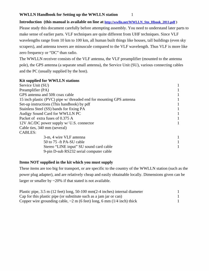
For your interest, not that you should need to know it, the inside of the preamplifier box is shown in Fig. 10 below.
Fig. 10. The inside of the preamplifier box. The input BNC is at left end of the picture, and the output through the Amphenol socket is at the extreme right.. The VLF signal from the BNC passes through a distributed RC filter which has attenuation in dB proportional to the square root of frequency. This is about 6 dB at 11 kHz and so is 60 dB at 1100 kHz (AM band), 600 dB at 110 MHz (FM and TV), etc. Following this, the VLF signal is clamped between ±10 V (the power rails are at ±15 V) by fast 0.5 A diodes for further protection against lightning impulse fields of up to 100 kV/m. The op-amp (744)
was chosen for high linearity rather than low noise. It has a gain of 11. The output driver (SSM2142), which can take a large capacitive load, splits the VLF into two phases.
The SSM2142 output driver allows the cable from the VLF preamplifier to the Service Unit to be quite long, maybe even 1000 metres, though we have not tested this.
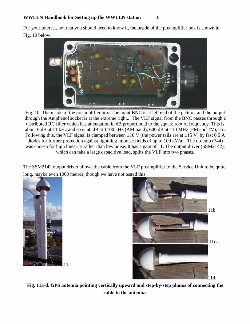
11a.
11b.
11c.
11d.Fig. 11a-d. GPS antenna pointing vertically upward and step-by-step photos of connecting the
cable to the antenna.

WWLLN Handbook for Setting up the WWLLN station 7
GPS antenna. The mounted GPS antenna is shown in Fig. 11a above. Not shown is the 50 ft of thick black coax (threaded through the plasic pipe followed by an adapter to thin coax (black) ending in a SMB (a very small connector designed for UHF and microwave frequencies) for direct connection to the back of the SU. To mount the GPS antenna, follow these instructions: 1.Place the plastic (PVC) tubing in front of you so that the threaded end faces the antenna. 2. Run the black coax (the end NOT connected to the brown SMB adapter) through the plastic tubing so that the threaded connector on the end of the coax comes out at the threaded end of the tubing (Figure 11b). 3. Screw the end of the black coax into the antenna (Figure 11c). 4. Slide the plastic tubing up the coax toward the antenna, and screw the tubing into the antenna (Figure 11d). 5. Mount the antenna by securing the 18” threaded pipe to a railing using black cable ties, or to any other vertical surface in any way you think will be secure (Figure 11a). Note: If you need a longer mounting pole, you may buy any hollow pipe or tubing with the proper threading to screw into the GPS antenna. However, if you need a longer cable from the GPS antenna to the SU, you should try to relocate your antenna, instead of lengthening the cable as the GPS signal is at GHz frequencies so adding an extra length of coax (between the white and black cables) may add too much attenuation. The GPS antenna must be mounted where it can “see” most of the sky but where it is within reach of the SU in the lab. Usually the GPS antenna is placed on the roof of the building housing the SU. If the 50 ft cable length is not adequate length, first try to find a location for it closer to the SU. For example, it may be satisfactory to mount the GPS antenna on a boom out of a window, provided it can see at least half of the sky. If you cannot mount it on a boom, and the SU must be housed further down than the cable reaches, try adding the required length of coax between the black and brown cables (this is unlikely to work for an added length greater than a few metres). Service Unit (SU) The SU, together with the preamplifier, constitutes the hardware part of the VLF lightning sensor. The SU must be housed indoors. The SU contains an electronics board which supplies the isolated (floating) power (± 15 V) to the preamplifier, and the isolation transformer (1:1). Both of these will withstand 1000 V. It also contains the GPS “engine” which generates the PPS (1 pulse per second) and the NMEA time code. The PPS is a 10 µs pulse. Its leading edge is well within 1 µs of true UTC, while the NMEA time code identifies this second of time. The computer itself runs RedHat 5.0 or clone, such as CentOS and contains software to measure lightning sferics. All WWLLN station computers are managed by WWLLN from Seattle and Dunedin.

WWLLN Handbook for Setting up the WWLLN station 8
Figure 12 shows all of the input and output connections, with the exception of the power to the SU (on the back of SU box).
Fig. 12. Annotated SU
Making connections: Connecting the GPS antenna cable to the SMB on the SU requires care. Push hard with a slight rocking motion until is clicks in. Note: it does not screw in! Plug in the cable from the preamplifier (5-pin miniDIN) to the miniDIN socket, and the stereo cable to the line input (blue) of the PC’s sound card. Connect the SU to the internet via an Ethernet cord (not provided in kit).

WWLLN Handbook for Setting up the WWLLN station 9
12V input power from AC/DC power supply connects into the back of the SU. You must put an adapter on the end of the power cord to be plugged into the wall if you are not in the United States. This adapter is not in the kit and must be bought by you locally since the pin configuration in power sockets varies from country to country. Once all cables are connected to the SU, power up by plugging in the power supply.
Yellow LEDs: Yellow LEDs monitor of the current to the preamplifier. The upper yellow LED is in series with the -15 V line and the lower yellow LED is in series with the +15 V line. While these LEDs draw no extra current, there is a voltage drop across each which reduces the plus and minus supply voltages to the preamplifier. This has little consequence. These LEDs indicate that the preamplifier is drawing power and so there is no break in the cable or plugs to the preamplifier.
Red LEDs: On power up, the upper red LED blinks only 2 or 3 times and stops. Then the lower red LED begins to flash every second, continuing indefinitely unless power is removed. After about 2 minutes, the upper red LED begins flashing at exactly one per second, slightly ahead of the lower red LED flashing. For your interest, the meaning of this is as follows: the initial upper red LED flashes merely indicated power up. The lower red LED is the indicator of the NMEA time code signal. While the lower red LED is flashing without the upper red LED, the NMEA signal is rubbish (the lower red LED will flash on its own even if the GPS antenna is not plugged into the SU). During this time (initially about 2 minutes when first installed at the site, but less than a minute on later restarts), the GPS engine is searching the sky for GPS satellites to get its position for correcting the PPS to within ±0.5 µs. Only when the upper red LED (the PPS indicator) begins flashing regularly is the PPS “true” and the NMEA sentence gives the correct time and position. If the upper red LED does not start flashing regularly after several minutes, or if it stops from time to time, either the GPS antenna is not seeing enough sky or you have added too much cable to the GPS antenna cable. Computer (PC) Only the CPU is is provided, not a screen or keyboard, since it is operated remotely. Arrange for the CPU to be permanently connected to the internet with a permanent IP address. The computer will have Red Hat linux installed with a sferix and root account, which WWLLN administrators have the password to. The software will be installed on the computer before it is sent to you, and we will have chosen a name for your site in the form of “togaxyz” where xyz are 3 or more letters to indicate the site (your university or city) to give a pronounceable name like “togamit” at MIT or “togadud” in Dunedin (DUD is the airport code). The minimum requirements are ssh access into your computer by username, ability to su to root, and continuous access to the internet for your computer to send packets to the central processing station through port 5555 using UDP and to provide the spectrogram for public access via the web (for an example of the latter, visit http://togasea.ess.washington.edu/~sferix/vlf.jpg ). The World-Wide Lightning Location Network (WWLLN) is hosted by more than 26 universities or institutes. The lightning sensor at any one site cannot locate lightning on its own — lightning location requires that the impulse (“sferic”) from a given lightning stroke be received at a minimum of four sites. Thus the WWLLN administrator needs root access and the computer needs continuous internet connection to send data packets continuously at an average rate of about 300 per minute (each packet has about 12 bytes of data, so about 5 MB/day is sent). An account with local (from inside your firewall) sudo access which gives your Administrator full root access for computer repairs is provided under the account name ‘host’. We will provide you with the

WWLLN Handbook for Setting up the WWLLN station 10
password for this account. It is very important for you to have access to this account, because we are not willing to provide the real root password. Finally, most of the problems we now experience are not problems with SU: either the computer is not powered on or the Internet has failed. Check: http://wwlln.net/manage/light.log.htm (ask Prof. Holzworth for access code, if needed) If there are no packets being sent (left-most column), check to make sure the SU is on, then check the LEDs on the back of the SU. Appendix: IF THERE IS A PROBLEM: If there is a problem with the preamp signal to the computer, we may ask you to look at the waveform of the lightning directly if you have a digital oscilloscope, like the one on the right. If we do ask you to look at the waveform with your oscilloscope, disconnect the stereo cable from the line in (blue socket) on the computer and instead connect it to the stereo-to-BNC adapter provided. Connect the BNC plug into your oscilloscope. Set the gain at 2V/cm and the time base at 200µs/cm. The trigger mode must be “Normal” so that a time sweep only occurs if the VLF voltage exceeds the trigger set. With the trigger set at 4 V as here, you may have to wait a few minutes for a strong sferic like this one to arrive. If you set the trigger much lower, you should catch a few hundred sferics per minute, depending on the time of day and season of the year.

WWLLN Handbook for Setting up the WWLLN station 11