wvr7200 multiformat multistandard waveform rasterizer · pdf filemultiformat, multistandard...
TRANSCRIPT
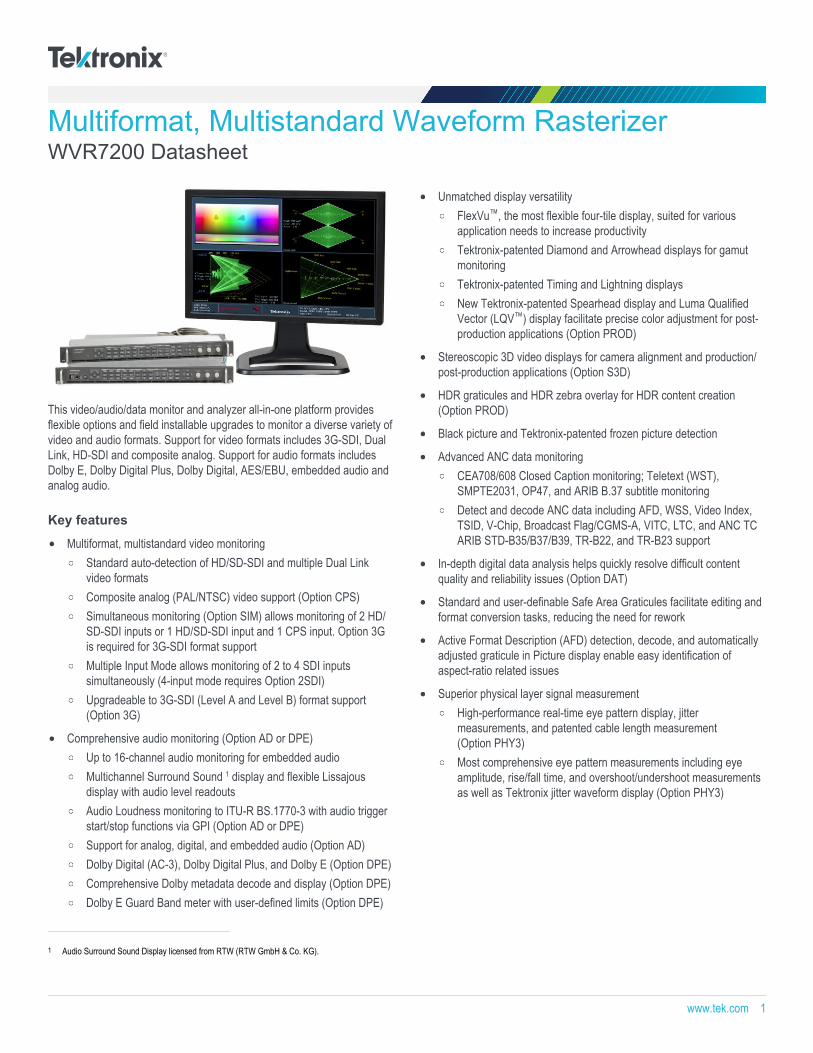
Multiformat, Multistandard Waveform RasterizerWVR7200 Datasheet
This video/audio/data monitor and analyzer all-in-one platform providesflexible options and field installable upgrades to monitor a diverse variety ofvideo and audio formats. Support for video formats includes 3G-SDI, DualLink, HD-SDI and composite analog. Support for audio formats includesDolby E, Dolby Digital Plus, Dolby Digital, AES/EBU, embedded audio andanalog audio.
Key features
Multiformat, multistandard video monitoringStandard auto-detection of HD/SD-SDI and multiple Dual Linkvideo formatsComposite analog (PAL/NTSC) video support (Option CPS)Simultaneous monitoring (Option SIM) allows monitoring of 2 HD/SD-SDI inputs or 1 HD/SD-SDI input and 1 CPS input. Option 3Gis required for 3G-SDI format supportMultiple Input Mode allows monitoring of 2 to 4 SDI inputssimultaneously (4-input mode requires Option 2SDI)Upgradeable to 3G-SDI (Level A and Level B) format support(Option 3G)
Comprehensive audio monitoring (Option AD or DPE)Up to 16-channel audio monitoring for embedded audioMultichannel Surround Sound 1 display and flexible Lissajousdisplay with audio level readoutsAudio Loudness monitoring to ITU-R BS.1770-3 with audio triggerstart/stop functions via GPI (Option AD or DPE)Support for analog, digital, and embedded audio (Option AD)Dolby Digital (AC-3), Dolby Digital Plus, and Dolby E (Option DPE)Comprehensive Dolby metadata decode and display (Option DPE)Dolby E Guard Band meter with user-defined limits (Option DPE)
Unmatched display versatilityFlexVu™, the most flexible four-tile display, suited for variousapplication needs to increase productivityTektronix-patented Diamond and Arrowhead displays for gamutmonitoringTektronix-patented Timing and Lightning displaysNew Tektronix-patented Spearhead display and Luma QualifiedVector (LQV™) display facilitate precise color adjustment for post-production applications (Option PROD)
Stereoscopic 3D video displays for camera alignment and production/post-production applications (Option S3D)
HDR graticules and HDR zebra overlay for HDR content creation(Option PROD)
Black picture and Tektronix-patented frozen picture detection
Advanced ANC data monitoringCEA708/608 Closed Caption monitoring; Teletext (WST),SMPTE2031, OP47, and ARIB B.37 subtitle monitoringDetect and decode ANC data including AFD, WSS, Video Index,TSID, V-Chip, Broadcast Flag/CGMS-A, VITC, LTC, and ANC TCARIB STD-B35/B37/B39, TR-B22, and TR-B23 support
In-depth digital data analysis helps quickly resolve difficult contentquality and reliability issues (Option DAT)
Standard and user-definable Safe Area Graticules facilitate editing andformat conversion tasks, reducing the need for rework
Active Format Description (AFD) detection, decode, and automaticallyadjusted graticule in Picture display enable easy identification ofaspect-ratio related issues
Superior physical layer signal measurementHigh-performance real-time eye pattern display, jittermeasurements, and patented cable length measurement(Option PHY3)Most comprehensive eye pattern measurements including eyeamplitude, rise/fall time, and overshoot/undershoot measurementsas well as Tektronix jitter waveform display (Option PHY3)
1 Audio Surround Sound Display licensed from RTW (RTW GmbH & Co. KG).
www.tek.com 1
Unmatched usabilityCaptureVu® advanced video frame data capture simplifiestroubleshooting and equipment setup32 instrument presets for quick recall of commonly usedconfigurations tailored to engineers or operatorsFront-panel USB port enables easy transfer of presets, capturedvideo frame data, screenshots, and error logFront-panel headphone port enables quick verification of selectedaudio pairIntuitive menu structure and context-sensitive helpExtensive alarms, status reporting, and error loggingSNMP and Ethernet remote interface capabilities and GPI controlfacilitate centralized monitoring and control
Applications
Monitoring and compliance checking in content distribution andbroadcast transmission
Quality control in content production and post-production
Equipment/system qualification and troubleshooting for installation andmaintenance of content creation and distribution facilities
Post-production edit suite and color correction monitoring
WVR7200 waveform rasterizerThe monitoring and measurement capabilities of this instrument provide acomprehensive suite of options and configurations to suit a variety ofapplications. For monitoring applications Tektronix-patented gamut displayssimplify color adjustments for camera balancing and color correctionapplications. Get information about the signal at a glance from the audiosession and video session displays that assist in ensuring quality control ofthe image.
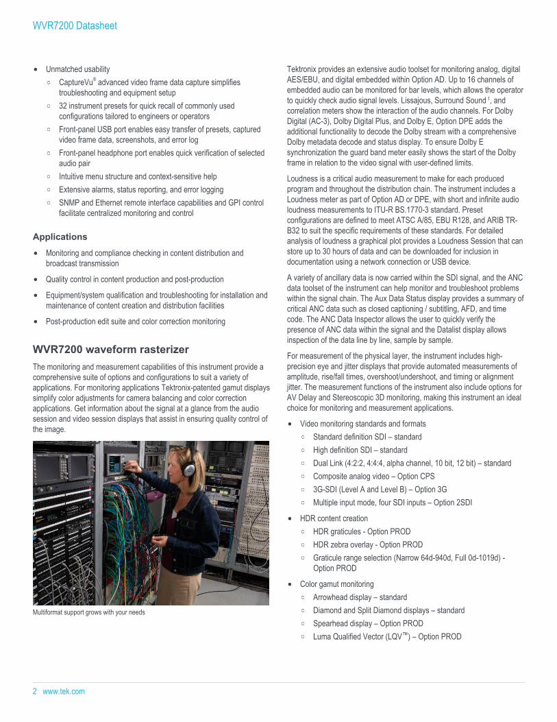
Multiformat support grows with your needs
Tektronix provides an extensive audio toolset for monitoring analog, digitalAES/EBU, and digital embedded within Option AD. Up to 16 channels ofembedded audio can be monitored for bar levels, which allows the operatorto quickly check audio signal levels. Lissajous, Surround Sound 1, andcorrelation meters show the interaction of the audio channels. For DolbyDigital (AC-3), Dolby Digital Plus, and Dolby E, Option DPE adds theadditional functionality to decode the Dolby stream with a comprehensiveDolby metadata decode and status display. To ensure Dolby Esynchronization the guard band meter easily shows the start of the Dolbyframe in relation to the video signal with user-defined limits.
Loudness is a critical audio measurement to make for each producedprogram and throughout the distribution chain. The instrument includes aLoudness meter as part of Option AD or DPE, with short and infinite audioloudness measurements to ITU-R BS.1770-3 standard. Presetconfigurations are defined to meet ATSC A/85, EBU R128, and ARIB TR-B32 to suit the specific requirements of these standards. For detailedanalysis of loudness a graphical plot provides a Loudness Session that canstore up to 30 hours of data and can be downloaded for inclusion indocumentation using a network connection or USB device.
A variety of ancillary data is now carried within the SDI signal, and the ANCdata toolset of the instrument can help monitor and troubleshoot problemswithin the signal chain. The Aux Data Status display provides a summary ofcritical ANC data such as closed captioning / subtitling, AFD, and timecode. The ANC Data Inspector allows the user to quickly verify thepresence of ANC data within the signal and the Datalist display allowsinspection of the data line by line, sample by sample.
For measurement of the physical layer, the instrument includes high-precision eye and jitter displays that provide automated measurements ofamplitude, rise/fall times, overshoot/undershoot, and timing or alignmentjitter. The measurement functions of the instrument also include options forAV Delay and Stereoscopic 3D monitoring, making this instrument an idealchoice for monitoring and measurement applications.
Video monitoring standards and formatsStandard definition SDI – standardHigh definition SDI – standardDual Link (4:2:2, 4:4:4, alpha channel, 10 bit, 12 bit) – standardComposite analog video – Option CPS3G-SDI (Level A and Level B) – Option 3GMultiple input mode, four SDI inputs – Option 2SDI
HDR content creationHDR graticules - Option PRODHDR zebra overlay - Option PRODGraticule range selection (Narrow 64d-940d, Full 0d-1019d) -Option PROD
Color gamut monitoringArrowhead display – standardDiamond and Split Diamond displays – standardSpearhead display – Option PRODLuma Qualified Vector (LQV™) – Option PROD
WVR7200 Datasheet
2 www.tek.com
Audio monitoring standards and formatsAnalog, digital AES/EBU, digital embedded – Option ADAnalog and digital including Dolby Digital, Dolby Digital Plus, andDolby E – Option DPE
Measurement and analysisAutomated eye pattern and jitter measurements – Option PHY3Color bar and pathological signal generation – Option GENDigital data analysis – Option DATANC Data Inspector – Option DATSimultaneous input monitoring – Option SIMStereoscopic 3D monitoring – Option S3DAudio/Video delay measurement – Option AVD
See and Solve™ with Tektronix displaysTektronix See and Solve™ displays simplify video monitoring tasks such ascalibration, error detection, and content correction allowing users to detecterrors at a glance and troubleshoot them efficiently. Specialized Sessionand Status displays provide summarized yet comprehensive reports ofconditions and measurements of content parameters.
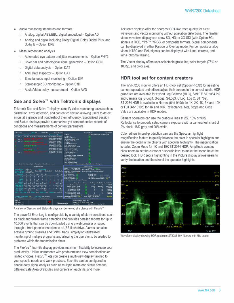
A variety of Session and Status displays can be viewed at a glance with FlexVu™
The powerful Error Log is configurable by a variety of alarm conditions suchas black and frozen frame detection and provides detailed reports for up to10,000 events that can be downloaded using a web browser or savedthrough a front-panel connection to a USB flash drive. Alarms can alsoactivate ground closures and SNMP traps, simplifying centralizedmonitoring of multiple programs and allowing the operator to be alerted toproblems within the transmission chain.
The FlexVu™ four-tile display provides maximum flexibility to increase yourproductivity. Unlike instruments with predetermined view combinations orlimited choices, FlexVu™ lets you create a multi-view display tailored toyour specific needs and work practices. Each tile can be configured toenable easy signal analysis such as multiple alarm and status screens,different Safe Area Graticules and cursors on each tile, and more.
Tektronix displays offer the sharpest CRT-like trace quality for clearwaveform and vector monitoring without pixelation distortions. The familiarvideo waveform display can show SD, HD, or 3G-SDI (with Option 3G)signals in RGB, YPbPr, YRGB, or composite formats. Signal componentscan be displayed in either Parade or Overlay mode. For composite analogvideo, NTSC and PAL signals can be displayed with luma, chroma, andluma+chroma filtering.
The Vector display offers user-selectable graticules, color targets (75% or100%), and color axis.
HDR tool set for content creatorsThe WVR7200 monitor offers an HDR tool set (Option PROD) for assistingcamera operators and editors adjust their content to the correct levels. HDRgraticules are available for Hybrid Log Gamma (HLG), SMPTE ST 2084 PQand Camera log (S-Log1, S-Log2, S-Log3, C Log, Log C, BT.709).ST 2084 HDR is available in Narrow (64d-940d) for 1K, 2K, 4K, 5K and 10Kor Full (4d-1019d) for 1K and 10K. Reflectance, Nits, Stops and CodeValue are available in HDR modes.
Camera operators can use the graticule lines at 2%, 18% or 90%Reflectance to properly setup camera exposure with a camera test chart of2% black, 18% gray and 90% white.
Color editors in post-production can use the Specular highlightmagnification feature to quickly balance the color in specular highlights andensure the detail in the objects with specular highlights. The magnificationis called Zoom Mode for 1K and 10K ST.2084 HDR. Amplitude cursorsallow users to set the cursor at a specific level to make the scene have thedesired look. HDR zebra highlighting in the Picture display allows users toverify the location and the size of the specular highlights.
Waveform display showing HDR graticule (ST2084 10K Narrow with Nits scale)
WVR7200 Datasheet
www.tek.com 3
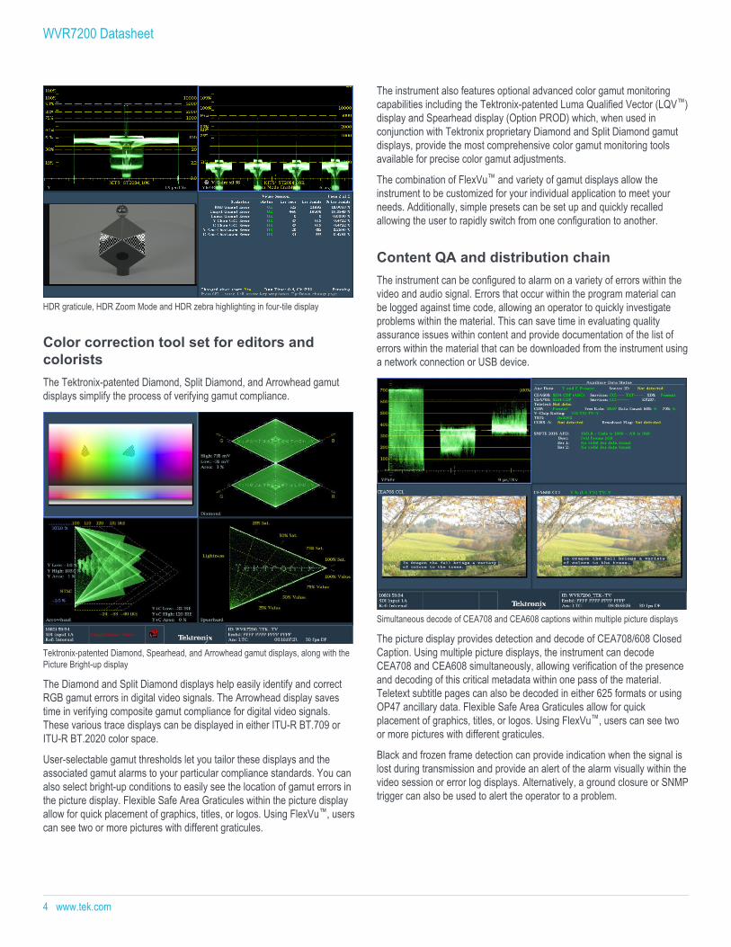
HDR graticule, HDR Zoom Mode and HDR zebra highlighting in four-tile display
Color correction tool set for editors andcoloristsThe Tektronix-patented Diamond, Split Diamond, and Arrowhead gamutdisplays simplify the process of verifying gamut compliance.
Tektronix-patented Diamond, Spearhead, and Arrowhead gamut displays, along with thePicture Bright-up display
The Diamond and Split Diamond displays help easily identify and correctRGB gamut errors in digital video signals. The Arrowhead display savestime in verifying composite gamut compliance for digital video signals.These various trace displays can be displayed in either ITU-R BT.709 orITU-R BT.2020 color space.
User-selectable gamut thresholds let you tailor these displays and theassociated gamut alarms to your particular compliance standards. You canalso select bright-up conditions to easily see the location of gamut errors inthe picture display. Flexible Safe Area Graticules within the picture displayallow for quick placement of graphics, titles, or logos. Using FlexVu™, userscan see two or more pictures with different graticules.
The instrument also features optional advanced color gamut monitoringcapabilities including the Tektronix-patented Luma Qualified Vector (LQV™)display and Spearhead display (Option PROD) which, when used inconjunction with Tektronix proprietary Diamond and Split Diamond gamutdisplays, provide the most comprehensive color gamut monitoring toolsavailable for precise color gamut adjustments.
The combination of FlexVu™ and variety of gamut displays allow theinstrument to be customized for your individual application to meet yourneeds. Additionally, simple presets can be set up and quickly recalledallowing the user to rapidly switch from one configuration to another.
Content QA and distribution chainThe instrument can be configured to alarm on a variety of errors within thevideo and audio signal. Errors that occur within the program material canbe logged against time code, allowing an operator to quickly investigateproblems within the material. This can save time in evaluating qualityassurance issues within content and provide documentation of the list oferrors within the material that can be downloaded from the instrument usinga network connection or USB device.
Simultaneous decode of CEA708 and CEA608 captions within multiple picture displays
The picture display provides detection and decode of CEA708/608 ClosedCaption. Using multiple picture displays, the instrument can decodeCEA708 and CEA608 simultaneously, allowing verification of the presenceand decoding of this critical metadata within one pass of the material.Teletext subtitle pages can also be decoded in either 625 formats or usingOP47 ancillary data. Flexible Safe Area Graticules allow for quickplacement of graphics, titles, or logos. Using FlexVu™, users can see twoor more pictures with different graticules.
Black and frozen frame detection can provide indication when the signal islost during transmission and provide an alert of the alarm visually within thevideo session or error log displays. Alternatively, a ground closure or SNMPtrigger can also be used to alert the operator to a problem.
WVR7200 Datasheet
4 www.tek.com
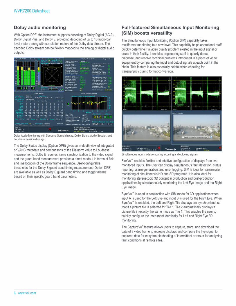
Camera balance applicationWithin a studio or on-location within a truck it is important that all thecameras are matched to ensure the look of the production from camera tocamera, scene to scene. With the Multiple Input mode, the instrument canbe used to monitor up to four SDI inputs simultaneously when in FullScreen mode (4-input mode requires Option 2SDI). This type of display isideal for camera balance applications where the user wishes to check thevideo level across multiple inputs to ensure consistency of the cameras’output. This Multiple Input mode is available within Waveform, Vector,Lightning, Diamond, Arrowhead, and Spearhead (with Option PROD)display modes, allowing for the comparison of video inputs across a widevariety of these displays. The instrument can also be set to either BT.709 orBT.2020 colorimetry for all of these display modes.
Multiple Input mode display of four SDI inputs with input labels for each signal
Complete monitoring tool set for optimumsound qualityThe instrument provides high-quality digital filtering and oversampling toinsure precise, reliable, and repeatable audio measurements. For easymonitoring, the WFM audio options provide format auto-detection andflexible mapping of audio inputs to analog or digital audio outputs forconnection to external devices.
The Audio display provides a variety of display configurations for audiolevel and phase monitoring. Up to 16 channels of embedded audio levelscan be monitored with a variety of scales and ballistics configured by theuser. For AES and embedded audio, eight audio channels can bemonitored for audio level with phase correlation meters. The Bars displayprovides indicators for faults, audio levels with direct level readouts, andDolby format information.
A Lissajous display can be enabled for a selected channel pair andprovides an X-Y plot of the audio signals. The flexible Lissajous displayallows the selection of any two audio channels. The Surround Sound 1
display provides intuitive graphical representation of channel interaction ina system.
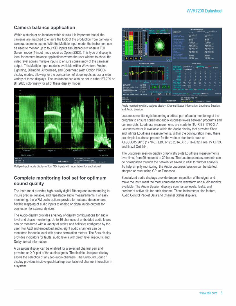
Audio monitoring with Lissajous display, Channel Status information, Loudness Session,and Audio Session
Loudness monitoring is becoming a critical part of audio monitoring of theprogram to ensure consistent audio loudness levels between programs andcommercials. Loudness measurements are made to ITU-R BS.1770-3. ALoudness meter is available within the Audio display that provides Shortand Infinite Loudness measurements. Within the configuration menu thereare simple Loudness presets for the various standards such asATSC A/85 2013 (1770-3), EBU R128 2014, ARIB TR-B32, Free TV OP59,and Brazil Ord 354.
The Loudness session display graphically plots Loudness measurementsover time, from 90 seconds to 30 hours. The Loudness measurements canbe downloaded through the network or saved to USB for further analysis.To help simplify monitoring, the Audio Loudness session can be started,stopped or reset using GPI or Timecode.
Specialized audio displays provide deeper inspection of the signal andmake the instrument the most comprehensive waveform and audio monitoravailable. The Audio Session displays summarize levels, faults, andnumber of active bits for each channel. These instruments also featureAudio Control Packet Data and Channel Status displays.
WVR7200 Datasheet
www.tek.com 5
Dolby audio monitoringWith Option DPE, the instrument supports decoding of Dolby Digital (AC-3),Dolby Digital Plus, and Dolby E, providing decoding of up to 10 audio barlevel meters along with correlation meters of the Dolby data stream. Thedecoded Dolby stream can be flexibly mapped to the analog or digital audiooutputs.
Dolby Audio Monitoring with Surround Sound display, Dolby Status, Audio Session, andLoudness Session displays
The Dolby Status display (Option DPE) gives an in-depth view of integratedor VANC metadata and comparisons of the Dialnorm value to Loudnessmeasurements. Dolby E requires frame synchronization to the video signaland the guard band measurement provides a direct readout in terms of fieldand line location of the Dolby frame sequence. User-configurablethresholds for the Dolby E guard band timing measurement (Option DPE)are available as well as Dolby E guard band timing and trigger alarmsbased on their specific guard band parameters.
Full-featured Simultaneous Input Monitoring(SIM) boosts versatilityThe Simultaneous Input Monitoring (Option SIM) capability takesmultiformat monitoring to a new level. This capability helps operational staffquickly determine if a video quality problem existed in the input signal orarose in their facility. It enables engineering staff to quickly detect,diagnose, and resolve technical problems introduced in a piece of videoequipment by comparing the input and output signals at each point in thechain. This feature is also especially helpful when checking fortransparency during format conversion.
Simultaneous Input mode comparing incoming and outgoing signals
FlexVu™ enables flexible and intuitive configuration of displays from twomonitored inputs. The user can display simultaneous fault detection, statusreporting, alarm generation, and error logging. SIM is ideal for transmissionmonitoring of simultaneous HD and SD programs. It is also ideal formonitoring stereoscopic 3D content in production and post-productionapplications by simultaneously monitoring the Left Eye image and the RightEye image.
SyncVu™ is used in conjunction with SIM mode for 3D applications wheninput A is used for the Left Eye and input B is used for the Right Eye. WhenSyncVu™ is enabled, the Left and Right Tile displays are synchronized, sothat if a picture tile is selected for Tile 1, Tile 2 automatically displays apicture tile in exactly the same mode as Tile 1. This enables the user toquickly configure the instrument identically for Left and Right Eye 3Dmonitoring.
The CaptureVu® feature allows users to capture, store, and download thedata of a video frame to recreate displays and compare the live signal tocaptured data for easy troubleshooting of intermittent errors or for analyzingfault conditions at remote sites.
WVR7200 Datasheet
6 www.tek.com
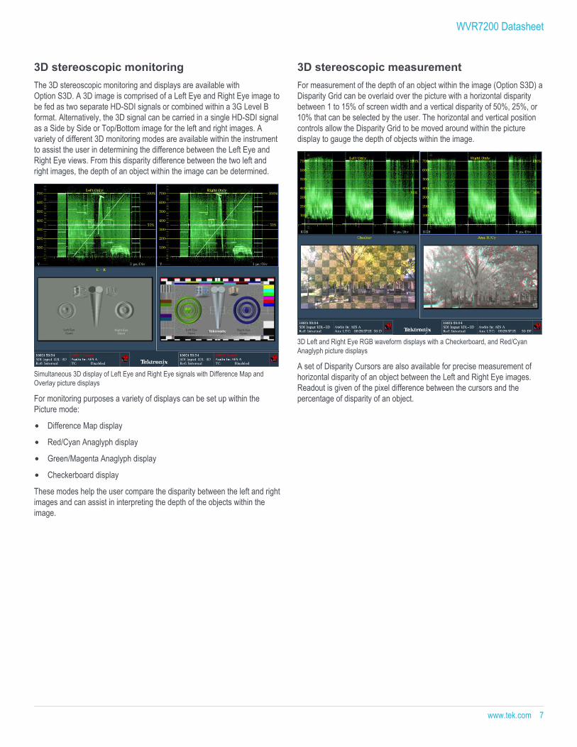
3D stereoscopic monitoringThe 3D stereoscopic monitoring and displays are available withOption S3D. A 3D image is comprised of a Left Eye and Right Eye image tobe fed as two separate HD-SDI signals or combined within a 3G Level Bformat. Alternatively, the 3D signal can be carried in a single HD-SDI signalas a Side by Side or Top/Bottom image for the left and right images. Avariety of different 3D monitoring modes are available within the instrumentto assist the user in determining the difference between the Left Eye andRight Eye views. From this disparity difference between the two left andright images, the depth of an object within the image can be determined.
Simultaneous 3D display of Left Eye and Right Eye signals with Difference Map andOverlay picture displays
For monitoring purposes a variety of displays can be set up within thePicture mode:
Difference Map display
Red/Cyan Anaglyph display
Green/Magenta Anaglyph display
Checkerboard display
These modes help the user compare the disparity between the left and rightimages and can assist in interpreting the depth of the objects within theimage.
3D stereoscopic measurementFor measurement of the depth of an object within the image (Option S3D) aDisparity Grid can be overlaid over the picture with a horizontal disparitybetween 1 to 15% of screen width and a vertical disparity of 50%, 25%, or10% that can be selected by the user. The horizontal and vertical positioncontrols allow the Disparity Grid to be moved around within the picturedisplay to gauge the depth of objects within the image.
3D Left and Right Eye RGB waveform displays with a Checkerboard, and Red/CyanAnaglyph picture displays
A set of Disparity Cursors are also available for precise measurement ofhorizontal disparity of an object between the Left and Right Eye images.Readout is given of the pixel difference between the cursors and thepercentage of disparity of an object.
WVR7200 Datasheet
www.tek.com 7
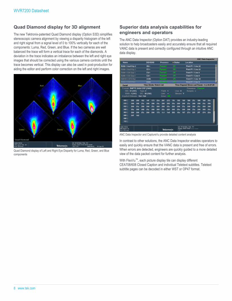
Quad Diamond display for 3D alignmentThe new Tektronix-patented Quad Diamond display (Option S3D) simplifiesstereoscopic camera alignment by viewing a disparity histogram of the leftand right signal from a signal level of 0 to 100% vertically for each of thecomponents: Luma, Red, Green, and Blue. If the two cameras are wellbalanced the trace will form a vertical trace for each of the diamonds. Adeviation in the trace indicates an imbalance between the left and right eyeimages that should be corrected using the various camera controls until thetrace becomes vertical. This display can also be used in post-production foraiding the editor and perform color correction on the left and right images.
Quad Diamond display of Left and Right Eye Disparity for Luma, Red, Green, and Bluecomponents
Superior data analysis capabilities forengineers and operatorsThe ANC Data Inspector (Option DAT) provides an industry-leadingsolution to help broadcasters easily and accurately ensure that all requiredVANC data is present and correctly configured through an intuitive ANCdata display.
ANC Data Inspector and CaptureVu provide detailed content analysis
In contrast to other solutions, the ANC Data Inspector enables operators toeasily and quickly ensure that the VANC data is present and free of errors.When errors are detected, engineers are quickly guided to a more detailedview of the data packet content for further analysis.
With FlexVu™, each picture display tile can display differentCEA708/608 Closed Caption and individual Teletext subtitles. Teletextsubtitle pages can be decoded in either WST or OP47 format.
WVR7200 Datasheet
8 www.tek.com
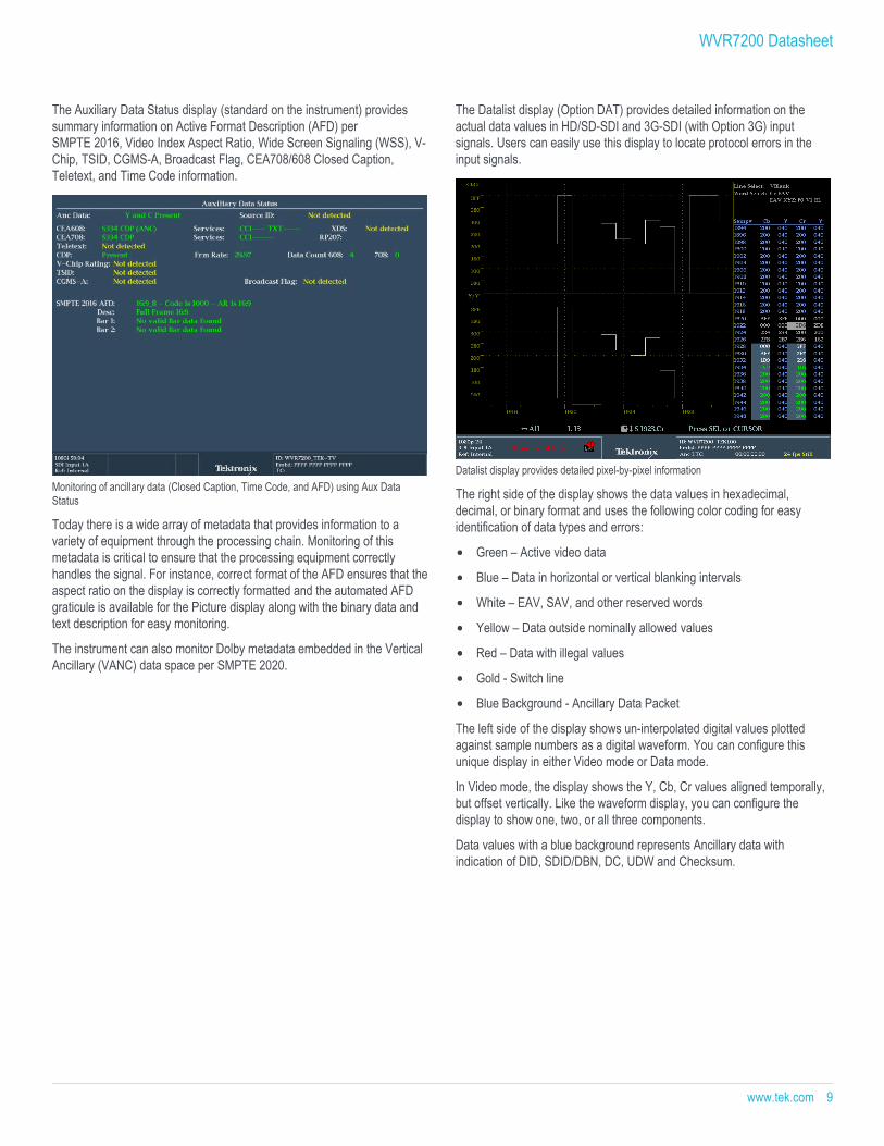
The Auxiliary Data Status display (standard on the instrument) providessummary information on Active Format Description (AFD) perSMPTE 2016, Video Index Aspect Ratio, Wide Screen Signaling (WSS), V-Chip, TSID, CGMS-A, Broadcast Flag, CEA708/608 Closed Caption,Teletext, and Time Code information.
Monitoring of ancillary data (Closed Caption, Time Code, and AFD) using Aux DataStatus
Today there is a wide array of metadata that provides information to avariety of equipment through the processing chain. Monitoring of thismetadata is critical to ensure that the processing equipment correctlyhandles the signal. For instance, correct format of the AFD ensures that theaspect ratio on the display is correctly formatted and the automated AFDgraticule is available for the Picture display along with the binary data andtext description for easy monitoring.
The instrument can also monitor Dolby metadata embedded in the VerticalAncillary (VANC) data space per SMPTE 2020.
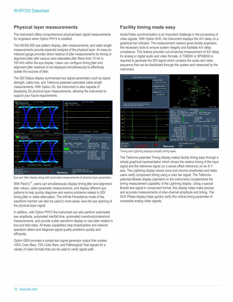
The Datalist display (Option DAT) provides detailed information on theactual data values in HD/SD-SDI and 3G-SDI (with Option 3G) inputsignals. Users can easily use this display to locate protocol errors in theinput signals.
Datalist display provides detailed pixel-by-pixel information
The right side of the display shows the data values in hexadecimal,decimal, or binary format and uses the following color coding for easyidentification of data types and errors:
Green – Active video data
Blue – Data in horizontal or vertical blanking intervals
White – EAV, SAV, and other reserved words
Yellow – Data outside nominally allowed values
Red – Data with illegal values
Gold - Switch line
Blue Background - Ancillary Data Packet
The left side of the display shows un-interpolated digital values plottedagainst sample numbers as a digital waveform. You can configure thisunique display in either Video mode or Data mode.
In Video mode, the display shows the Y, Cb, Cr values aligned temporally,but offset vertically. Like the waveform display, you can configure thedisplay to show one, two, or all three components.
Data values with a blue background represents Ancillary data withindication of DID, SDID/DBN, DC, UDW and Checksum.
WVR7200 Datasheet
www.tek.com 9
Physical layer measurementsThe instrument offers comprehensive physical-layer signal measurementsfor engineers when Option PHY3 is installed.
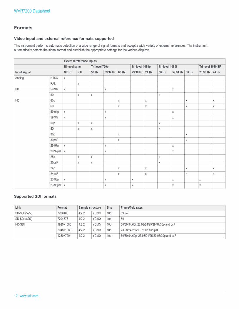
The HD/SD-SDI eye pattern display, jitter measurements, and cable lengthmeasurements provide essential analysis of the physical layer. An easy-to-interpret gauge provides direct readout of jitter measurements for timing oralignment jitter with various user-selectable jitter filters from 10 Hz to100 kHz within the eye display. Users can configure timing jitter andalignment jitter readouts to be displayed simultaneously to effectivelyisolate the sources of jitter.
The SDI Status display summarizes key signal parameters such as signalstrength, cable loss, and Tektronix-patented estimated cable lengthmeasurements. With Option 3G, the instrument is also capable ofdisplaying 3G physical layer measurements, allowing the instrument tosupport your future requirements.
Eye and Jitter display along with automated measurements of physical layer parameters
With FlexVu™, users can simultaneously display timing jitter and alignmentjitter values, cable parameter measurements, and display different eyepatterns to help quickly diagnose and resolve problems related to SDItiming jitter or cable attenuation. The Infinite Persistence mode of thewaveform monitor can also be used to more easily view the eye opening ofthe physical layer signal.
In addition, with Option PHY3 the instrument can also perform automatedeye amplitude, automated rise/fall time, automated overshoot/undershootmeasurements, and provide a jitter waveform display to view jitter related toline and field rates. All these capabilities help broadcasters and networkoperators detect and diagnose signal quality problems quickly andefficiently.
Option GEN provides a simple test signal generator output that creates100% Color Bars, 75% Color Bars, and Pathological Test signals for avariety of video formats that can be used to verify signal path.
Facility timing made easyAudio/Video synchronization is an important challenge in the processing ofvideo signals. With Option AVD, the instrument displays the A/V delay on agraphical bar indicator. The measurement readout gives facility engineersthe necessary tools to ensure system integrity and facilitate A/V delaycompliance. This feature provides out-of-service measurement of A/V delayfor analog or digital audio and video formats. A TG8000 or SPG8000 isrequired to generate the SDI signal which contains the audio and videosequence that can be distributed through the system and measured by theinstrument.
Timing and Lightning displays simplify timing tasks
The Tektronix-patented Timing display makes facility timing easy through asimple graphical representation which shows the relative timing of the inputsignal and the reference signal (or a saved offset reference) on an X-Yaxis. The Lightning display shows luma and chroma amplitudes and helpsusers verify component timing using a color bar signal. The Tektronix-patented Bowtie display (standard on the instrument) complements thetiming measurement capability of the Lightning display. Using a specialBowtie test signal in component format, this display helps make preciseand accurate measurements of inter-channel amplitude and timing. TheSCH Phase display helps quickly verify this critical timing parameter ofcomposite analog video signals.
WVR7200 Datasheet
10 www.tek.com

WVR8RFP remote front panelThe instrument can be controlled by the newly designed WVR8FRP remotefront panel, which has the same control button and knob configuration asthe front panel on the instrument. The remote front panel allows operatorsto access and control the instrument from a distance of up to 1000 ft. withpower supplied from the base instrument through the cable. Users can alsochoose to connect the remote front panel with an external 12 V DC powersource which can extend the distance of the cable run to 4000 ft.
WVR7200 Datasheet
www.tek.com 11
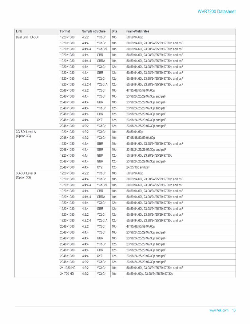
Formats
Video input and external reference formats supported
This instrument performs automatic detection of a wide range of signal formats and accept a wide variety of external references. The instrumentautomatically detects the signal format and establish the appropriate settings for the various displays.
External reference inputsBi-level sync Tri-level 720p Tri-level 1080p Tri-level 1080i Tri-level 1080 SF
Input signal NTSC PAL 50 Hz 59.94 Hz 60 Hz 23.98 Hz 24 Hz 50 Hz 59.94 Hz 60 Hz 23.98 Hz 24 HzAnalog NTSC x
PAL xSD 59.94i x x x
50i x x xHD 60p x x x x
60i x x x x59.94p x x x59.94i x x x50p x x x50i x x x30p x x30psF x x29.97p x x x29.97psF x x x25p x x x25psF x x x24p x x x x24psF x x x x23.98p x x x x x23.98psF x x x x x
Supported SDI formats
Link Format Sample structure Bits Frame/field ratesSD-SDI (525i) 720×486 4:2:2 YCbCr 10b 59.94iSD-SDI (625i) 720×576 4:2:2 YCbCr 10b 50iHD-SDI 1920×1080 4:2:2 YCbCr 10b 50/59.94/60i, 23.98/24/25/29.97/30p and psF
2048×1080 4:2:2 YCbCr 10b 23.98/24/25/29.97/30p and psF1280×720 4:2:2 YCbCr 10b 50/59.94/60p, 23.98/24/25/29.97/30p and psF
WVR7200 Datasheet
12 www.tek.com
Link Format Sample structure Bits Frame/field ratesDual Link HD-SDI 1920×1080 4:2:2 YCbCr 10b 50/59.94/60p
1920×1080 4:4:4 YCbCr 10b 50/59.94/60i, 23.98/24/25/29.97/30p and psF1920×1080 4:4:4:4 YCbCrA 10b 50/59.94/60i, 23.98/24/25/29.97/30p and psF1920×1080 4:4:4 GBR 10b 50/59.94/60i, 23.98/24/25/29.97/30p and psF1920×1080 4:4:4:4 GBRA 10b 50/59.94/60i, 23.98/24/25/29.97/30p and psF1920×1080 4:4:4 YCbCr 12b 50/59.94/60i, 23.98/24/25/29.97/30p and psF1920×1080 4:4:4 GBR 12b 50/59.94/60i, 23.98/24/25/29.97/30p and psF1920×1080 4:2:2 YCbCr 12b 50/59.94/60i, 23.98/24/25/29.97/30p and psF1920×1080 4:2:2:4 YCbCrA 12b 50/59.94/60i, 23.98/24/25/29.97/30p and psF2048×1080 4:2:2 YCbCr 10b 47.95/48/50/59.94/60p2048×1080 4:4:4 YCbCr 10b 23.98/24/25/29.97/30p and psF2048×1080 4:4:4 GBR 10b 23.98/24/25/29.97/30p and psF2048×1080 4:4:4 YCbCr 12b 23.98/24/25/29.97/30p and psF2048×1080 4:4:4 GBR 12b 23.98/24/25/29.97/30p and psF2048×1080 4:4:4 XYZ 12b 23.98/24/25/29.97/30p and psF2048×1080 4:2:2 YCbCr 12b 23.98/24/25/29.97/30p and psF
3G-SDI Level A(Option 3G)
1920×1080 4:2:2 YCbCr 10b 50/59.94/60p2048×1080 4:2:2 YCbCr 10b 47.95/48/50/59.94/60p1920×1080 4:4:4 GBR 10b 50/59.94/60i, 23.98/24/25/29.97/30p and psF2048×1080 4:4:4 GBR 10b 23.98/24/25/29.97/30p and psF1920×1080 4:4:4 GBR 12b 50/59.94/60i, 23.98/24/25/29.97/30p2048×1080 4:4:4 GBR 12b 23.98/24/25/29.97/30p and psF2048×1080 4:4:4 XYZ 12b 24/25/30p and psF
3G-SDI Level B(Option 3G)
1920×1080 4:2:2 YCbCr 10b 50/59.94/60p1920×1080 4:4:4 YCbCr 10b 50/59.94/60i, 23.98/24/25/29.97/30p and psF1920×1080 4:4:4:4 YCbCrA 10b 50/59.94/60i, 23.98/24/25/29.97/30p and psF1920×1080 4:4:4 GBR 10b 50/59.94/60i, 23.98/24/25/29.97/30p and psF1920×1080 4:4:4:4 GBRA 10b 50/59.94/60i, 23.98/24/25/29.97/30p and psF1920×1080 4:4:4 YCbCr 12b 50/59.94/60i, 23.98/24/25/29.97/30p and psF1920×1080 4:4:4 GBR 12b 50/59.94/60i, 23.98/24/25/29.97/30p and psF1920×1080 4:2:2 YCbCr 12b 50/59.94/60i, 23.98/24/25/29.97/30p and psF1920×1080 4:2:2:4 YCbCrA 12b 50/59.94/60i, 23.98/24/25/29.97/30p and psF2048×1080 4:2:2 YCbCr 10b 47.95/48/50/59.94/60p2048×1080 4:4:4 YCbCr 10b 23.98/24/25/29.97/30p and psF2048×1080 4:4:4 GBR 10b 23.98/24/25/29.97/30p and psF2048×1080 4:4:4 YCbCr 12b 23.98/24/25/29.97/30p and psF2048×1080 4:4:4 GBR 12b 23.98/24/25/29.97/30p and psF2048×1080 4:4:4 XYZ 12b 23.98/24/25/29.97/30p and psF2048×1080 4:2:2 YCbCr 12b 23.98/24/25/29.97/30p and psF2× 1080 HD 4:2:2 YCbCr 10b 50/59.94/60i, 23.98/24/25/29.97/30p and psF2× 720 HD 4:2:2 YCbCr 10b 50/59.94/60p, 23.98/24/25/29.97/30p
WVR7200 Datasheet
www.tek.com 13
SpecificationsAll specifications apply to all models unless noted otherwise.
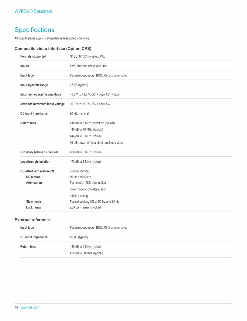
Composite video interface (Option CPS)
Formats supported NTSC, NTSC no setup, PAL
Inputs Two, only one active at a time
Input type Passive loopthrough BNC, 75 Ω compensated
Input dynamic range ±6 dB (typical)
Maximum operating amplitude –1.8 V to +2.2 V, DC + peak AC (typical)
Absolute maximum input voltage –6.0 V to +6.0 V, DC + peak AC
DC input impedance 20 kΩ, nominal
Return loss >40 dB to 6 MHz, power on (typical)
>40 dB to 10 MHz (typical)
>46 dB to 6 MHz (typical)
35 dB, power off (standard amplitude video)
Crosstalk between channels >60 dB to 6 MHz (typical)
Loopthrough isolation >70 dB to 6 MHz (typical)
DC offset with restore off <20 mV (typical)DC restore 50 Hz and 60 HzAttenuation Fast mode >95% attenuation
Slow mode <10% attenuation
<10% peakingSlow mode Typical peaking 8% at 50 Hz and 60 HzLock range ±50 ppm remains locked
External reference
Input type Passive loopthrough BNC, 75 Ω compensated
DC input impedance 15 kΩ (typical)
Return loss >40 dB to 6 MHz (typical)
>35 dB to 30 MHz (typical)
WVR7200 Datasheet
14 www.tek.com
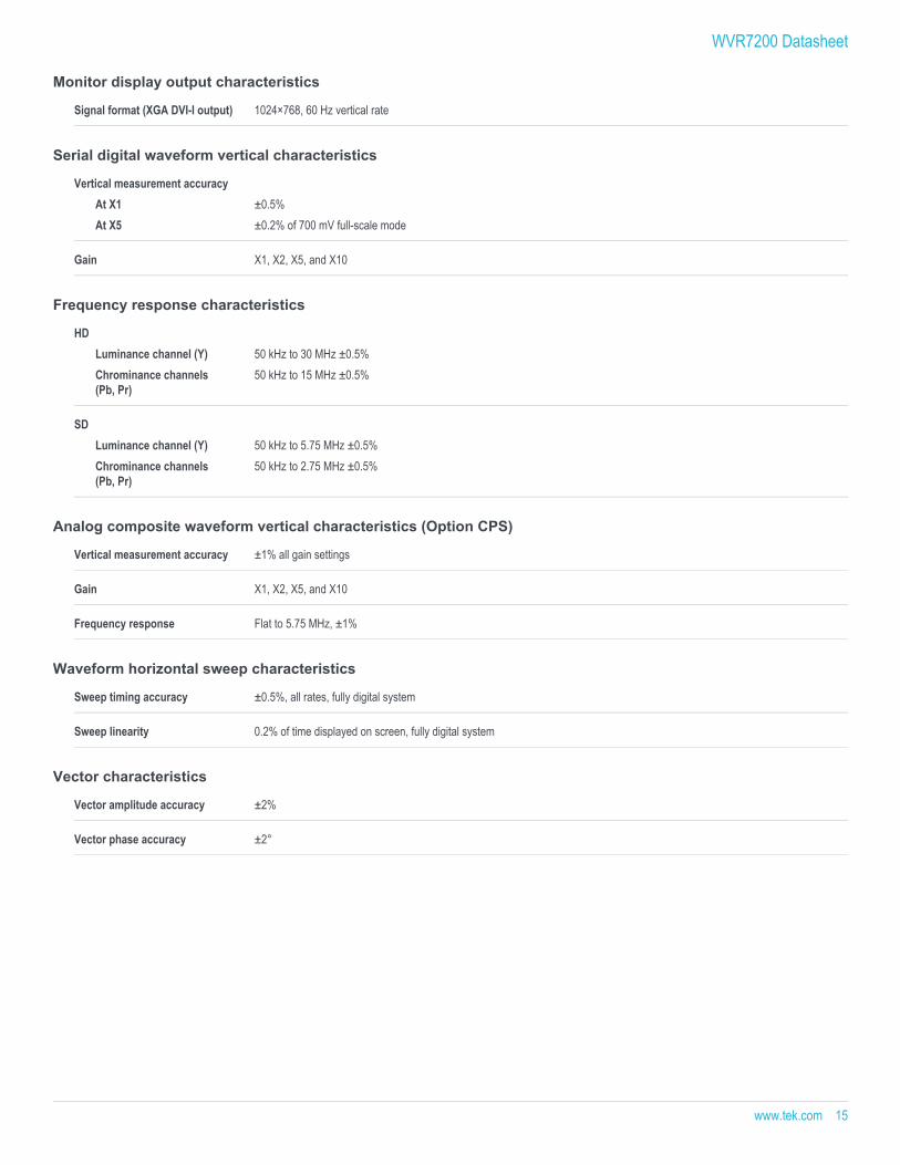
Monitor display output characteristics
Signal format (XGA DVI-I output) 1024×768, 60 Hz vertical rate
Serial digital waveform vertical characteristics
Vertical measurement accuracyAt X1 ±0.5%At X5 ±0.2% of 700 mV full-scale mode
Gain X1, X2, X5, and X10
Frequency response characteristics
HDLuminance channel (Y) 50 kHz to 30 MHz ±0.5%Chrominance channels(Pb, Pr)
50 kHz to 15 MHz ±0.5%
SDLuminance channel (Y) 50 kHz to 5.75 MHz ±0.5%Chrominance channels(Pb, Pr)
50 kHz to 2.75 MHz ±0.5%
Analog composite waveform vertical characteristics (Option CPS)
Vertical measurement accuracy ±1% all gain settings
Gain X1, X2, X5, and X10
Frequency response Flat to 5.75 MHz, ±1%
Waveform horizontal sweep characteristics
Sweep timing accuracy ±0.5%, all rates, fully digital system
Sweep linearity 0.2% of time displayed on screen, fully digital system
Vector characteristics
Vector amplitude accuracy ±2%
Vector phase accuracy ±2°
WVR7200 Datasheet
www.tek.com 15
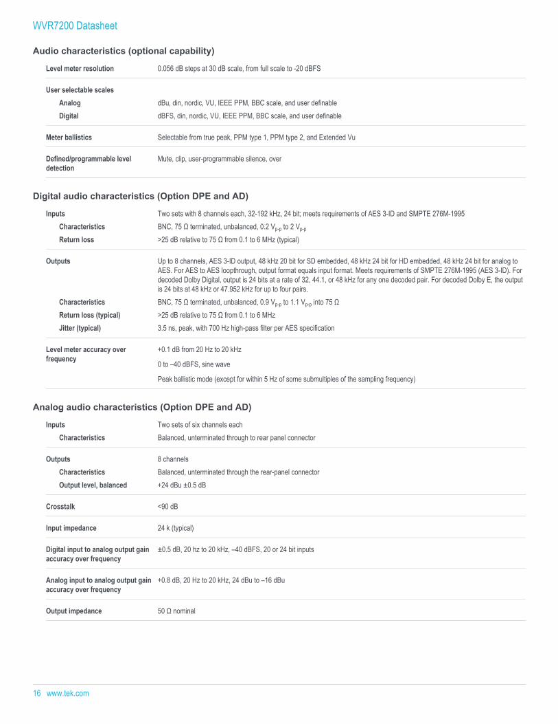
Audio characteristics (optional capability)
Level meter resolution 0.056 dB steps at 30 dB scale, from full scale to -20 dBFS
User selectable scalesAnalog dBu, din, nordic, VU, IEEE PPM, BBC scale, and user definableDigital dBFS, din, nordic, VU, IEEE PPM, BBC scale, and user definable
Meter ballistics Selectable from true peak, PPM type 1, PPM type 2, and Extended Vu
Defined/programmable leveldetection
Mute, clip, user-programmable silence, over
Digital audio characteristics (Option DPE and AD)
Inputs Two sets with 8 channels each, 32-192 kHz, 24 bit; meets requirements of AES 3-ID and SMPTE 276M-1995 Characteristics BNC, 75 Ω terminated, unbalanced, 0.2 Vp-p to 2 Vp-p
Return loss >25 dB relative to 75 Ω from 0.1 to 6 MHz (typical)
Outputs Up to 8 channels, AES 3-ID output, 48 kHz 20 bit for SD embedded, 48 kHz 24 bit for HD embedded, 48 kHz 24 bit for analog toAES. For AES to AES loopthrough, output format equals input format. Meets requirements of SMPTE 276M-1995 (AES 3-ID). Fordecoded Dolby Digital, output is 24 bits at a rate of 32, 44.1, or 48 kHz for any one decoded pair. For decoded Dolby E, the outputis 24 bits at 48 kHz or 47.952 kHz for up to four pairs.
Characteristics BNC, 75 Ω terminated, unbalanced, 0.9 Vp-p to 1.1 Vp-p into 75 ΩReturn loss (typical) >25 dB relative to 75 Ω from 0.1 to 6 MHzJitter (typical) 3.5 ns, peak, with 700 Hz high-pass filter per AES specification
Level meter accuracy overfrequency
+0.1 dB from 20 Hz to 20 kHz
0 to –40 dBFS, sine wave
Peak ballistic mode (except for within 5 Hz of some submultiples of the sampling frequency)
Analog audio characteristics (Option DPE and AD)
Inputs Two sets of six channels eachCharacteristics Balanced, unterminated through to rear panel connector
Outputs 8 channelsCharacteristics Balanced, unterminated through the rear-panel connectorOutput level, balanced +24 dBu ±0.5 dB
Crosstalk <90 dB
Input impedance 24 k (typical)
Digital input to analog output gainaccuracy over frequency
±0.5 dB, 20 hz to 20 kHz, –40 dBFS, 20 or 24 bit inputs
Analog input to analog output gainaccuracy over frequency
+0.8 dB, 20 Hz to 20 kHz, 24 dBu to –16 dBu
Output impedance 50 Ω nominal
WVR7200 Datasheet
16 www.tek.com
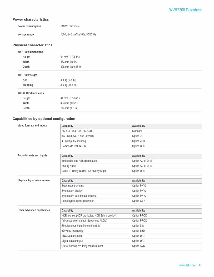
Power characteristics
Power consumption 110 W, maximum
Voltage range 100 to 240 VAC ±10%; 50/60 Hz
Physical characteristics
WVR7200 dimensionsHeight 44 mm (1.725 in.)Width 483 mm (19 in.)Depth 498 mm (19.625 in.)
WVR7200 weightNet 4.3 kg (9.5 lb.)Shipping 8.5 kg (18.5 lb.)
WVR8FRP dimensionsHeight 44 mm (1.725 in.)Width 483 mm (19 in.)Depth 114 mm (4.5 in.)
Capabilities by optional configuration
Video formats and inputs Capability AvailabilityHD-SDI / Dual Link / SD-SDI Standard3G-SDI (Level A and Level B) Option 3G4 SDI Input Monitoring Option 2SDIComposite PAL/NTSC Option CPS
Audio formats and inputs Capability AvailabilityEmbedded and AES digital audio Option AD or DPEAnalog Audio Option AD or DPEDolby E / Dolby Digital Plus / Dolby Digital Option DPE
Physical layer measurement Capability AvailabilityJitter measurements Option PHY3Eye pattern display Option PHY3Eye pattern auto measurements Option PHY3Pathological signal generation Option GEN
Other advanced capabilities Capability AvailabilityHDR tool set (HDR graticules, HDR Zebra overlay) Option PRODAdvanced color gamut (Spearhead / LQV) Option PRODSimultaneous Input Monitoring (SIM) Option SIM3D video monitoring Option S3DANC Data Inspector Option DATDigital data analysis Option DATOut-of-service AV delay measurement Option AVD
WVR7200 Datasheet
www.tek.com 17
Ordering information
ModelsWVR7200 SDI rasterizer, 2 SDI inputs (auto-detection of SDI format); base unit includes HD-SDI, SD-SDI, Dual Link signal formats; Option
3G required for 3G-SDI support
WVR720UP This field upgrade allows you to upgrade your existing WFM7200 with any of the available WFM7200 options
WVR8RFP Remote front panel allows control of the WVR7200 front panel at up to a distance of 1000 ft.; an external 12 V DC power supplyallows control up to 4000 ft.
Options
WVR7200 and WVR720UP options
2SDI Adds additional SDI module (in slot 2) to support up to 4 SDI inputs within multi-mode displays (3G-SDI, HD-SDI, and SD-SDIsupport on the same inputs – auto detect).
Option 3G required for 3G-SDI support.
This option cannot be installed on an instrument with option CPS installed.
3G Adds support for 3G-SDI signal formats (Level A and Level B). (Upgrades are available by a software option key.)
AD Adds analog audio monitoring (2 sets of 6-channel analog audio inputs and 8-channel analog audio outputs) plus 16 channels,embedded or AES/EBU digital audio support (8 channels at a time), including loudness monitoring.
AVD Adds support for out-of-service A/V delay measurement. Option AD or DPE required.
CPS Adds support for composite analog video monitoring; 2 composite analog inputs; passive loopthrough.
This option cannot be installed on an instrument with option 2SDI installed.
DAT Add advanced 3G / Dual-Link / HD / SD-SDI data analyzer and ancillary data analyzer (Datalist and ANC data Inspector). Option3G required for 3G-SDI support.
DPE Adds option AD capabilities (analog and digital audio – embedded or external AES) plus support for decoding and monitoringDolby E, Dolby D, and Dolby Digital Plus including loudness monitoring.
GEN Adds 3G/HD/SD-SDI color bar and pathological signal generation capability. Option 3G required for 3G-SDI signal generationcapability.
PHY3 Physical layer measurement package (includes automated measurement of 3G/HD/SD eye pattern parameters, jitter, and cableparameters; jitter waveform display). Option 3G required for 3G-SDI physical layer measurements.
PROD Advanced gamut monitoring package (Spearhead Gamut display and Luma Qualified Vector display) and HDR tool set (HDRgraticules, HDR Zebra overlay).
S3D Add monitoring support for stereoscopic 3D video (including Simultaneous Input Monitoring capability).
SIM Add simultaneous monitoring of two 3G/HD/SD-SDI inputs or one 3G/HD/SD-SDI input and one CPS input. Option 3G required for3G-SDI format support.
62 Analog audio breakout cable, 6 feet, male 62-pin connectors to 8 XLR male output connectors and 12 XLR female inputconnectors.
WVR7200 Datasheet
18 www.tek.com
Power plug options
Opt. A0 North America power plug (115 V, 60 Hz)
Opt. A1 Universal Euro power plug (220 V, 50 Hz)
Opt. A2 United Kingdom power plug (240 V, 50 Hz)
Opt. A3 Australia power plug (240 V, 50 Hz)
Opt. A5 Switzerland power plug (220 V, 50 Hz)
Opt. A6 Japan power plug (100 V, 50/60 Hz)
Opt. A10 China power plug (50 Hz)
Opt. A11 India power plug (50 Hz)
Opt. A12 Brazil power plug (60 Hz)
Opt. A99 No power cord
Service options
Opt. C3 Calibration Service 3 Years
Opt. C5 Calibration Service 5 Years
Opt. D1 Calibration Data Report
Opt. D3 Calibration Data Report 3 Years (with Opt. C3)
Opt. D5 Calibration Data Report 5 Years (with Opt. C5)
Opt. G3 Complete Care 3 Years (includes loaner, scheduled calibration, and more)
Opt. G5 Complete Care 5 Years (includes loaner, scheduled calibration, and more)
Opt. R3 Repair Service 3 Years (including warranty)
Opt. R3DW Repair Service Coverage 3 Years (includes product warranty period). 3-year period starts at time of instrument purchase
Opt. R5 Repair Service 5 Years (including warranty)
Opt. R5DW Repair Service Coverage 5 Years (includes product warranty period). 5-year period starts at time of instrument purchase
WVR7200 Datasheet
www.tek.com 19
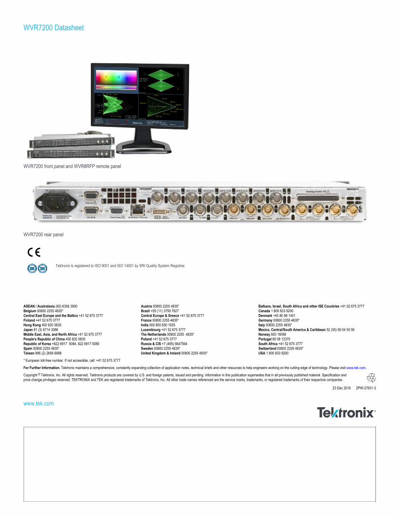
WVR7200 front panel and WVR8RFP remote panel
WVR7200 rear panel
Tektronix is registered to ISO 9001 and ISO 14001 by SRI Quality System Registrar.
WVR7200 Datasheet
ASEAN / Australasia (65) 6356 3900 Austria 00800 2255 4835* Balkans, Israel, South Africa and other ISE Countries +41 52 675 3777 Belgium 00800 2255 4835* Brazil +55 (11) 3759 7627 Canada 1 800 833 9200 Central East Europe and the Baltics +41 52 675 3777 Central Europe & Greece +41 52 675 3777 Denmark +45 80 88 1401 Finland +41 52 675 3777 France 00800 2255 4835* Germany 00800 2255 4835*Hong Kong 400 820 5835 India 000 800 650 1835 Italy 00800 2255 4835*Japan 81 (3) 6714 3086 Luxembourg +41 52 675 3777 Mexico, Central/South America & Caribbean 52 (55) 56 04 50 90 Middle East, Asia, and North Africa +41 52 675 3777 The Netherlands 00800 2255 4835* Norway 800 16098 People's Republic of China 400 820 5835 Poland +41 52 675 3777 Portugal 80 08 12370 Republic of Korea +822 6917 5084, 822 6917 5080 Russia & CIS +7 (495) 6647564 South Africa +41 52 675 3777 Spain 00800 2255 4835* Sweden 00800 2255 4835* Switzerland 00800 2255 4835*Taiwan 886 (2) 2656 6688 United Kingdom & Ireland 00800 2255 4835* USA 1 800 833 9200
* European toll-free number. If not accessible, call: +41 52 675 3777
For Further Information. Tektronix maintains a comprehensive, constantly expanding collection of application notes, technical briefs and other resources to help engineers working on the cutting edge of technology. Please visit www.tek.com.
Copyright © Tektronix, Inc. All rights reserved. Tektronix products are covered by U.S. and foreign patents, issued and pending. Information in this publication supersedes that in all previously published material. Specification andprice change privileges reserved. TEKTRONIX and TEK are registered trademarks of Tektronix, Inc. All other trade names referenced are the service marks, trademarks, or registered trademarks of their respective companies.
23 Dec 2016 2PW-27631-3
www.tek.com