wÜrth industrie service inch fasteners - wuerth.de€¦ · inch fasteners 6 ansi-standards –...
TRANSCRIPT

WÜRTH Industrie Service
INCHFASTENERS
Introduction 2
American Threads 3
ANSI-Standards 5
Mechanical Properties 8
Comparison Head Markings Metric and Inch 9
Heads and Drives 11
Points 12
Full and Partial Threads 13
Table of contents Page

2INCH FASTENERS
Dear Würth Industrie Service Customers!
Within the Würth Group Würth Industrie Service is respon-
sible for supplying the industrial sector as a full service
provider of C-Parts. Originally the company was founded
as an independent subsidiary in the "Industriepark Würth"
Bad Mergentheim in January 1999, by the outsourcing of
the Industry Division of the Adolf Würth GmbH & Co. KG
in Künzelsau.
A wide range of C-Parts as well as one of a kind supply
concept make Wurth IndustrieService the perfect sup-
plier for C-Parts in the industry sector. Our product range
focuses on the needs and demands of the industry sector
for manufacturing, which includes assembly material for
contructions, machines and vehicles as well as equipment
for their maintenance.
Most U.S. companies that utilise inch fasteners in their
assembly process, export those products or also have pro-
ductions sites in Europe. This is why it was important to us
to add inch fasteners to our already wide range of C-parts.
This brochure serves to give an overview of the characteri-
stics of these products. Furthermore, it provides additional
information on the mechanical properties as well as the
according standards.
We look forward to do business with you and thank you
for your trust.
Dr. Uwe Hasselmann
Head of Technical Department
Introduction
3 INCH FASTENERS
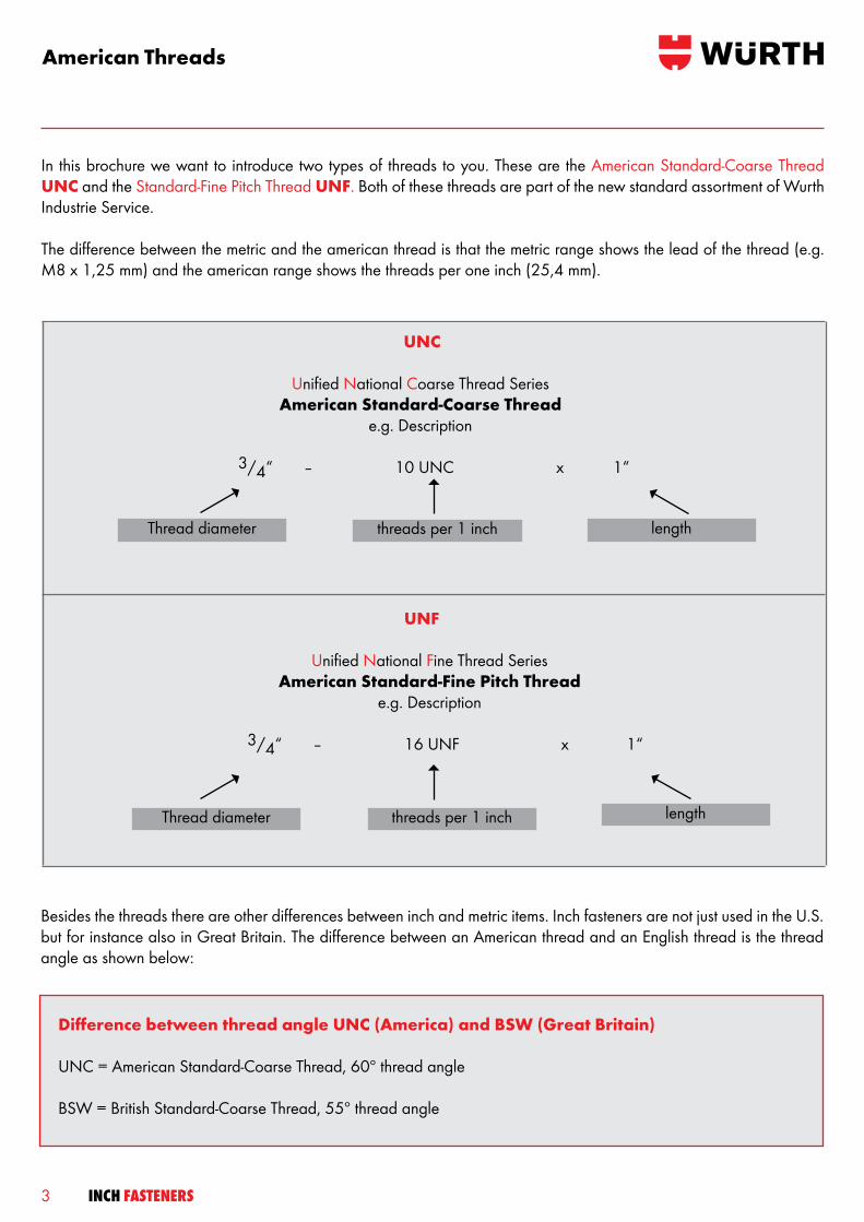
American Threads
UNF
Unified National Fine Thread SeriesAmerican Standard-Fine Pitch Thread
e.g. Description
3/4“ – 16 UNF x 1“
UNC
Unified National Coarse Thread SeriesAmerican Standard-Coarse Thread
e.g. Description
3/4“ – 10 UNC x 1“
Thread diameter threads per 1 inch length
Thread diameter threads per 1 inch length
Difference between thread angle UNC (America) and BSW (Great Britain)
UNC = American Standard-Coarse Thread, 60º thread angle
BSW = British Standard-Coarse Thread, 55º thread angle
Besides the threads there are other differences between inch and metric items. Inch fasteners are not just used in the U.S. but for instance also in Great Britain. The difference between an American thread and an English thread is the thread angle as shown below:
In this brochure we want to introduce two types of threads to you. These are the American Standard-Coarse Thread UNC and the Standard-Fine Pitch Thread UNF. Both of these threads are part of the new standard assortment of Wurth Industrie Service.
The difference between the metric and the american thread is that the metric range shows the lead of the thread (e.g. M8 x 1,25 mm) and the american range shows the threads per one inch (25,4 mm).
4INCH FASTENERS
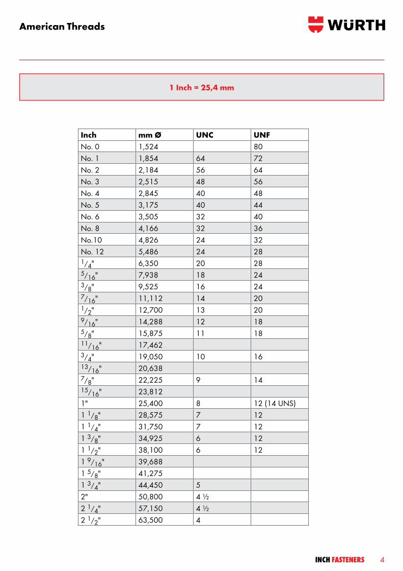
American Threads
1 Inch = 25,4 mm
Inch mm Ø UNC UNFNo. 0 1,524 80No. 1 1,854 64 72No. 2 2,184 56 64No. 3 2,515 48 56No. 4 2,845 40 48No. 5 3,175 40 44No. 6 3,505 32 40No. 8 4,166 32 36No.10 4,826 24 32No. 12 5,486 24 281/4" 6,350 20 285/16" 7,938 18 243/8" 9,525 16 247/16" 11,112 14 201/2" 12,700 13 209/16" 14,288 12 185/8" 15,875 11 1811/16" 17,462 3/4" 19,050 10 1613/16" 20,638 7/8" 22,225 9 1415/16" 23,812 1" 25,400 8 12 (14 UNS)1 1/8" 28,575 7 121 1/4" 31,750 7 121 3/8" 34,925 6 121 1/2" 38,100 6 121 9/16" 39,688 1 5/8" 41,275 1 3/4" 44,450 5 2" 50,800 4 ½ 2 1/4" 57,150 4 ½ 2 1/2" 63,500 4
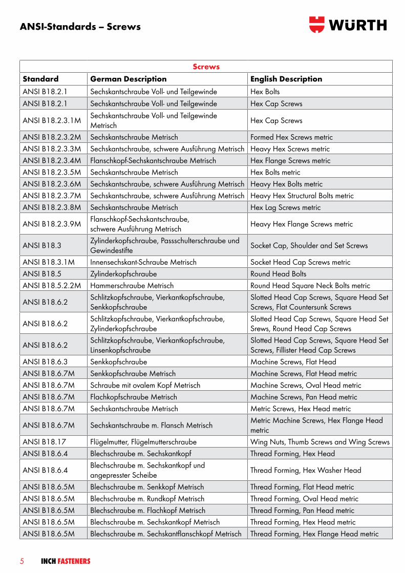
ANSI-Standards – Screws
ScrewsStandard German Description English DescriptionANSI B18.2.1 Sechskantschraube Voll- und Teilgewinde Hex BoltsANSI B18.2.1 Sechskantschraube Voll- und Teilgewinde Hex Cap Screws
ANSI B18.2.3.1M Sechskantschraube Voll- und Teilgewinde Metrisch Hex Cap Screws
ANSI B18.2.3.2M Sechskantschraube Metrisch Formed Hex Screws metricANSI B18.2.3.3M Sechskantschraube, schwere Ausführung Metrisch Heavy Hex Screws metricANSI B18.2.3.4M Flanschkopf-Sechskantschraube Metrisch Hex Flange Screws metricANSI B18.2.3.5M Sechskantschraube Metrisch Hex Bolts metricANSI B18.2.3.6M Sechskantschraube, schwere Ausführung Metrisch Heavy Hex Bolts metricANSI B18.2.3.7M Sechskantschraube, schwere Ausführung Metrisch Heavy Hex Structural Bolts metricANSI B18.2.3.8M Sechskantschraube Metrisch Hex Lag Screws metric
ANSI B18.2.3.9M Flanschkopf-Sechskantschraube, schwere Ausführung Metrisch Heavy Hex Flange Screws metric
ANSI B18.3 Zylinderkopfschraube, Passschulterschraube und Gewindestifte Socket Cap, Shoulder and Set Screws
ANSI B18.3.1M Innensechskant-Schraube Metrisch Socket Head Cap Screws metricANSI B18.5 Zylinderkopfschraube Round Head BoltsANSI B18.5.2.2M Hammerschraube Metrisch Round Head Square Neck Bolts metric
ANSI B18.6.2 Schlitzkopfschraube, Vierkantkopfschraube, Senkkopfschraube
Slotted Head Cap Screws, Square Head Set Screws, Flat Countersunk Screws
ANSI B18.6.2 Schlitzkopfschraube, Vierkantkopfschraube, Zylinderkopfschraube
Slotted Head Cap Screws, Square Head Set Srews, Round Head Cap Screws
ANSI B18.6.2 Schlitzkopfschraube, Vierkantkopfschraube, Linsenkopfschraube
Slotted Head Cap Screws, Square Head Set Screws, Fillister Head Cap Screws
ANSI B18.6.3 Senkkopfschraube Machine Screws, Flat HeadANSI B18.6.7M Senkkopfschraube Metrisch Machine Screws, Flat Head metricANSI B18.6.7M Schraube mit ovalem Kopf Metrisch Machine Screws, Oval Head metricANSI B18.6.7M Flachkopfschraube Metrisch Machine Screws, Pan Head metricANSI B18.6.7M Sechskantschraube Metrisch Metric Screws, Hex Head metric
ANSI B18.6.7M Sechskantschraube m. Flansch Metrisch Metric Machine Screws, Hex Flange Head metric
ANSI B18.17 Flügelmutter, Flügelmutterschraube Wing Nuts, Thumb Screws and Wing ScrewsANSI B18.6.4 Blechschraube m. Sechskantkopf Thread Forming, Hex Head
ANSI B18.6.4 Blechschraube m. Sechskantkopf und angepresster Scheibe Thread Forming, Hex Washer Head
ANSI B18.6.5M Blechschraube m. Senkkopf Metrisch Thread Forming, Flat Head metricANSI B18.6.5M Blechschraube m. Rundkopf Metrisch Thread Forming, Oval Head metricANSI B18.6.5M Blechschraube m. Flachkopf Metrisch Thread Forming, Pan Head metricANSI B18.6.5M Blechschraube m. Sechskantkopf Metrisch Thread Forming, Hex Head metricANSI B18.6.5M Blechschraube m. Sechskantflanschkopf Metrisch Thread Forming, Hex Flange Head metric
5 INCH FASTENERS
6INCH FASTENERS
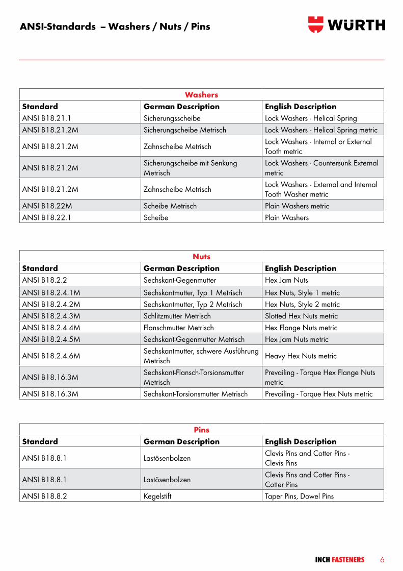
ANSI-Standards – Washers / Nuts / Pins
NutsStandard German Description English DescriptionANSI B18.2.2 Sechskant-Gegenmutter Hex Jam NutsANSI B18.2.4.1M Sechskantmutter, Typ 1 Metrisch Hex Nuts, Style 1 metricANSI B18.2.4.2M Sechskantmutter, Typ 2 Metrisch Hex Nuts, Style 2 metricANSI B18.2.4.3M Schlitzmutter Metrisch Slotted Hex Nuts metricANSI B18.2.4.4M Flanschmutter Metrisch Hex Flange Nuts metricANSI B18.2.4.5M Sechskant-Gegenmutter Metrisch Hex Jam Nuts metric
ANSI B18.2.4.6M Sechskantmutter, schwere Ausführung Metrisch Heavy Hex Nuts metric
ANSI B18.16.3M Sechskant-Flansch-Torsionsmutter Metrisch
Prevailing - Torque Hex Flange Nuts metric
ANSI B18.16.3M Sechskant-Torsionsmutter Metrisch Prevailing - Torque Hex Nuts metric
PinsStandard German Description English Description
ANSI B18.8.1 Lastösenbolzen Clevis Pins and Cotter Pins - Clevis Pins
ANSI B18.8.1 Lastösenbolzen Clevis Pins and Cotter Pins - Cotter Pins
ANSI B18.8.2 Kegelstift Taper Pins, Dowel Pins
WashersStandard German Description English DescriptionANSI B18.21.1 Sicherungsscheibe Lock Washers - Helical SpringANSI B18.21.2M Sicherungscheibe Metrisch Lock Washers - Helical Spring metric
ANSI B18.21.2M Zahnscheibe Metrisch Lock Washers - Internal or External Tooth metric
ANSI B18.21.2M Sicherungscheibe mit Senkung Metrisch
Lock Washers - Countersunk External metric
ANSI B18.21.2M Zahnscheibe Metrisch Lock Washers - External and Internal Tooth Washer metric
ANSI B18.22M Scheibe Metrisch Plain Washers metricANSI B18.22.1 Scheibe Plain Washers
7 INCH FASTENERS
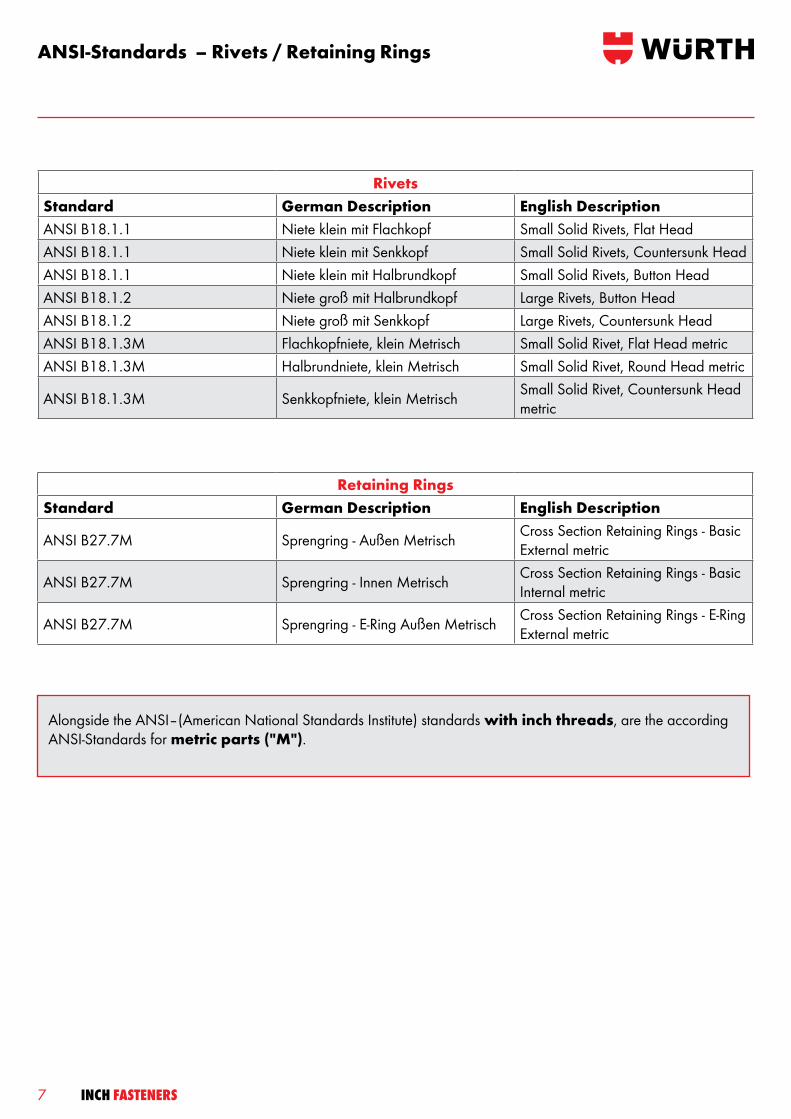
ANSI-Standards – Rivets / Retaining Rings
Retaining RingsStandard German Description English Description
ANSI B27.7M Sprengring - Außen Metrisch Cross Section Retaining Rings - Basic External metric
ANSI B27.7M Sprengring - Innen Metrisch Cross Section Retaining Rings - Basic Internal metric
ANSI B27.7M Sprengring - E-Ring Außen Metrisch Cross Section Retaining Rings - E-Ring External metric
RivetsStandard German Description English DescriptionANSI B18.1.1 Niete klein mit Flachkopf Small Solid Rivets, Flat HeadANSI B18.1.1 Niete klein mit Senkkopf Small Solid Rivets, Countersunk HeadANSI B18.1.1 Niete klein mit Halbrundkopf Small Solid Rivets, Button HeadANSI B18.1.2 Niete groß mit Halbrundkopf Large Rivets, Button HeadANSI B18.1.2 Niete groß mit Senkkopf Large Rivets, Countersunk HeadANSI B18.1.3M Flachkopfniete, klein Metrisch Small Solid Rivet, Flat Head metricANSI B18.1.3M Halbrundniete, klein Metrisch Small Solid Rivet, Round Head metric
ANSI B18.1.3M Senkkopfniete, klein Metrisch Small Solid Rivet, Countersunk Head metric
Alongside the ANSI–(American National Standards Institute) standards with inch threads, are the according ANSI-Standards for metric parts ("M").
8INCH FASTENERS
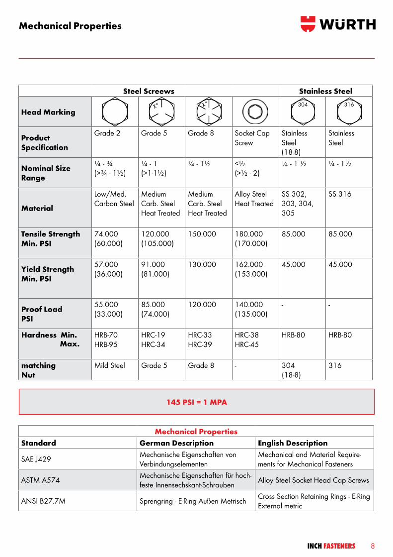
Mechanical Properties
Steel Screews Stainless Steel
Head Marking
Product Specification
Grade 2 Grade 5 Grade 8 Socket Cap Screw
Stainless Steel(18-8)
Stainless Steel
Nominal Size Range
¼ - ¾ (>¾ - 1½)
¼ - 1 (>1-1½)
¼ - 1½ <½ (>½ - 2)
¼ - 1 ½ ¼ - 1½
Material
Low/Med. Carbon Steel
Medium Carb. Steel Heat Treated
Medium Carb. Steel Heat Treated
Alloy Steel Heat Treated
SS 302, 303, 304, 305
SS 316
Tensile Strength Min. PSI
74.000 (60.000)
120.000 (105.000)
150.000 180.000 (170.000)
85.000 85.000
Yield StrengthMin. PSI
57.000 (36.000)
91.000 (81.000)
130.000 162.000 (153.000)
45.000 45.000
Proof Load PSI
55.000 (33.000)
85.000 (74.000)
120.000 140.000 (135.000)
- -
Hardness Min.
HRB-70 HRB-95
HRC-19 HRC-34
HRC-33 HRC-39
HRC-38 HRC-45
HRB-80 HRB-80
matching Nut
Mild Steel Grade 5 Grade 8 - 304(18-8)
316
304 316X* X*
Mechanical PropertiesStandard German Description English Description
SAE J429 Mechanische Eigenschaften von Verbindungselementen
Mechanical and Material Require-ments for Mechanical Fasteners
ASTM A574 Mechanische Eigenschaften für hoch-feste Innensechskant-Schrauben Alloy Steel Socket Head Cap Screws
ANSI B27.7M Sprengring - E-Ring Außen Metrisch Cross Section Retaining Rings - E-Ring External metric
Max.
145 PSI = 1 MPA

9 INCH FASTENERS
Metric and Inch Class Comparison
ASTM A574 < ½“ – 180,000 psi
> ½“ – 170,000 psi
5.8
X*
6.8
X*
8.8
X*
9.8
X*
10.9
X*
12.9
X*
L 9® (Grade 9)(Proprietory product)L9
X* Grade 5(up to 1“)
X* Grade 7
X* Grade 8
75.420
87.023
≈ 520 class 5.8
≈ 600 class 6.8
X* Grade 5(over 1“)
4.8
X*
5.6
X*
X*no
mark
Grade 2(up to 3/4“)
4.6
X*
X*no
markGrade 2(over 3/4“)
58.015
60.000
≈ 400 class 4.6
≈ 414
60.916
74.000
72.519
≈ 420 class 4.8
≈ 510
≈ 500 class 5.6
105.000 ≈ 724
120.000
120.381
≈ 827
≈ 830 class 8.8
130.534 ≈ 900 class 9.8
133.000 ≈ 916
150.000 ≈ 1034
150.839 ≈ 1040 class 10.9
176.946 ≈ 1220 class 12.9
180.000 ≈ 1240 class 12.9
The classes and grades are not equal, they are just similar!
INCH Fasteners Pounds per Inch² (psi)
METRIC Fasteners(MPa) Megapascal
_

10INCH FASTENERS
11 INCH FASTENERS
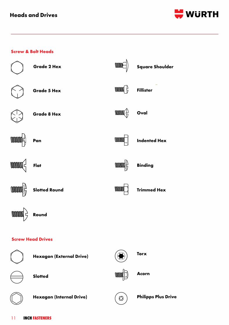
Heads and Drives
Screw & Bolt Heads
Philipps Plus Drive
Screw Head Drives
Hexagon (External Drive)
Slotted
Hexagon (Internal Drive)
Torx
Acorn
Trimmed Hex
Square ShoulderGrade 2 Hex
Grade 5 Hex
Grade 8 Hex
Pan
Flat
Slotted Round
Round
Fillister
Oval
Indented Hex
Binding
12INCH FASTENERS
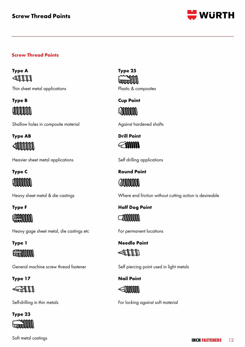
Screw Thread Points
Type A
Thin sheet metal applications
Type B
Shallow holes in composite material Type AB
Heavier sheet metal applications
Type C
Heavy sheet metal & die castings
Type F
Heavy gage sheet metal, die castings etc
Type 1
General machine screw thread fastener Type 17
Self-drilling in thin metals Type 23
Soft metal castings
Type 25
Plastic & composites
Cup Point
Against hardened shafts
Drill Point
Self drilling applications
Round Point
Where end friction without cutting action is desireable
Half Dog Point
For permanent locations
Needle Point
Self piercing point used in light metals
Nail Point
For locking against soft material
Screw Thread Points

13 INCH FASTENERS
No-minal diame-ter
1/4 5/16 3/8 7/16 1/2 9/16
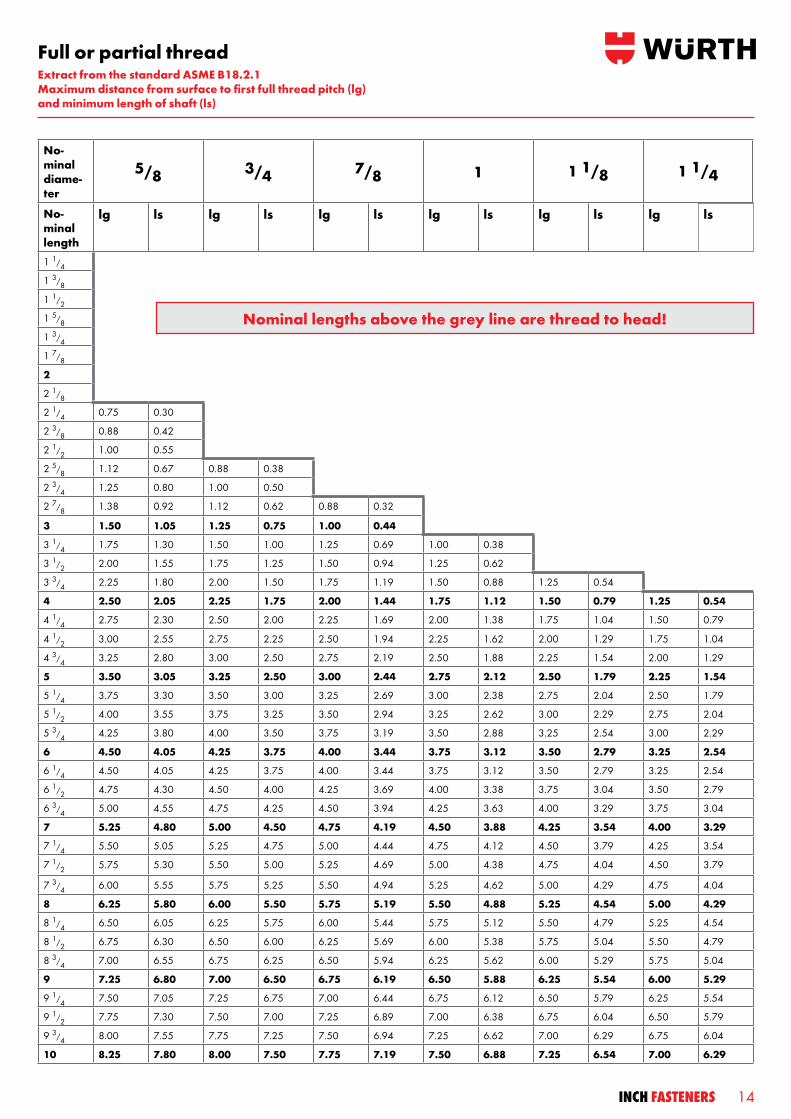
Full or partial thread
No-minal length
lg ls lg ls lg ls lg ls lg ls lg ls
1 1/4 0.50 0.25
1 3/8 0.63 0.38 0.50 0.22
1 1/2 0.75 0.50 0.62 0.35 0.50 0.19
1 5/8 0.88 0.62 0.75 0.47 0.62 0.31
1 3/4 1.00 0.75 0.88 0.60 0.75 0.44 0.63 0.27
1 7/8 1.12 0.88 1.00 0.72 0.88 0.56 0.75 0.39 0.63 0.24
2 1.25 1.00 1.12 0.85 1.00 0.59 0.88 0.52 0.75 0.38
2 1/8 1.38 1.12 1.25 0.97 1.12 0.81 1.00 0.64 0.88 0.49 0.75 0.33
2 1/4 1.50 1.25 1.38 1.10 1.25 0.94 1.12 0.77 1.00 0.52 0.88 0.46
2 3/8 1.62 1.38 1.50 1.22 1.38 1.06 1.25 0.89 1.12 0.74 1.00 0.58
2 1/2 1.75 1.50 1.62 1.35 1.50 1.19 1.38 1.02 1.25 0.86 1.12 0.75
2 5/8 1.88 1.62 1.75 1.47 1.62 1.31 1.50 1.14 1.38 0.99 1.25 0.83
2 3/4 2.00 1.75 1.88 1.60 1.75 1.44 1.62 1.27 1.50 1.12 1.38 0.96
2 7/8 2.12 1.88 2.00 1.72 1.88 1.56 1.75 1.39 1.62 1.24 1.50 1.08
3 2.25 2.00 2.12 1.85 2.00 1.69 1.88 1.52 1.75 1.36 1.62 1.21
3 1/4 2.50 2.25 2.38 2.10 2.25 1.94 2.12 1.77 2.00 1.62 1.88 1.46
3 1/2 2.75 2.50 2.62 2.35 2.50 2.19 2.38 2.02 2.25 1.86 2.12 1.71
3 3/4 3.00 2.75 2.88 2.60 2.75 2.44 2.62 2.27 2.50 2.12 2.38 1.96
4 3.25 3.00 3.12 2.85 3.00 2.69 2.88 2.52 2.75 2.36 2.62 2.21
4 1/4 3.50 3.25 3.38 3.10 3.25 2.94 3.12 2.77 3.00 2.62 2.88 2.46
4 1/2 3.75 3.50 3.62 3.35 3.50 3.19 3.38 3.02 3.25 2.86 3.12 2.71
4 3/4 4.00 3.75 3.88 3.60 3.75 3.44 3.62 3.27 3.50 3.12 3.38 2.96
5 4.25 4.00 4.12 3.85 4.00 3.69 3.88 3.52 3.75 3.36 3.62 3.21
5 1/4 4.50 4.25 4.38 4.10 4.25 3.94 4.12 3.77 4.00 3.62 3.88 3.46
5 1/2 4.75 4.50 4.62 4.35 4.50 4.19 4.38 4.02 4.25 3.87 4.12 3.71
5 3/4 5.00 4.75 4.88 4.60 4.75 4.44 4.63 4.27 4.50 4.12 4.38 3.96
6 5.25 5.00 5.12 4.85 5.00 4.69 4.88 4.52 4.75 4.36 4.62 4.21
6 1/4 5.25 5.00 5.12 4.85 5.00 4.69 4.88 4.52 4.75 4.36 4.62 4.21
6 1/2 5.50 5.25 5.38 5.10 5.25 4.94 5.12 4.77 5.00 4.62 4.88 4.46
6 3/4 5.75 5.50 5.62 5.35 5.50 5.19 5.38 5.02 5.25 4.86 5.12 4.71
7 6.00 5.75 5.88 5.80 5.75 5.44 5.62 5.27 5.50 5.12 5.38 4.96
7 1/4 6.25 6.00 6.12 5.85 6.00 5.69 5.88 5.52 5.75 5.36 5.62 5.20
7 1/2 6.50 6.25 6.38 6.10 6.25 5.94 6.12 5.77 6.00 5.62 5.88 5.46
7 3/4 6.75 6.50 6.62 6.35 6.50 6.19 6.38 6.02 6.25 5.87 6.12 5.71
8 7.00 6.75 6.88 6.60 6.75 6.44 6.62 6.27 6.50 6.12 6.38 5.96
8 1/4 7.25 7.00 7.12 6.85 7.00 6.69 6.88 6.52 6.75 6.36 6.62 6.21
8 1/2 7.50 7.25 7.38 7.10 7.25 6.94 7.12 6.77 7.00 6.62 6.88 6.46
8 3/4 7.75 7.50 7.62 7.35 7.50 7.19 7.38 7.02 7.25 6.86 7.12 6.71
9 8.00 7.75 7.88 7.60 7.75 7.44 7.62 7.27 7.50 7.12 7.38 6.96
9 1/4 8.25 8.00 8.12 7.85 8.00 7.69 7.88 7.52 7.75 7.36 7.62 7.21
9 1/2 8.50 8.25 8.38 8.10 8.25 7.94 8.12 7.77 8.00 7.62 7.88 7.46
9 3/4 8.75 8.50 8.62 8.35 8.50 8.19 8.38 8.02 8.25 7.86 8.12 7.71
10 9.00 8.75 8.88 8.60 8.75 8.44 8.62 8.27 8.50 8.12 8.38 7.96
Extract from the standard ASME B18.2.1Maximum distance from surface to first full thread pitch (lg)and minimum length of shaft (ls)
14INCH FASTENERS
Full or partial thread
No-minal length
lg ls lg ls lg ls lg ls lg ls lg ls
1 1/4 0.50 0.25
1 3/8 0.63 0.38 0.50 0.22
1 1/2 0.75 0.50 0.62 0.35 0.50 0.19
1 5/8 0.88 0.62 0.75 0.47 0.62 0.31
1 3/4 1.00 0.75 0.88 0.60 0.75 0.44 0.63 0.27
1 7/8 1.12 0.88 1.00 0.72 0.88 0.56 0.75 0.39 0.63 0.24
2 1.25 1.00 1.12 0.85 1.00 0.59 0.88 0.52 0.75 0.38
2 1/8 1.38 1.12 1.25 0.97 1.12 0.81 1.00 0.64 0.88 0.49 0.75 0.33
2 1/4 1.50 1.25 1.38 1.10 1.25 0.94 1.12 0.77 1.00 0.52 0.88 0.46
2 3/8 1.62 1.38 1.50 1.22 1.38 1.06 1.25 0.89 1.12 0.74 1.00 0.58
2 1/2 1.75 1.50 1.62 1.35 1.50 1.19 1.38 1.02 1.25 0.86 1.12 0.75
2 5/8 1.88 1.62 1.75 1.47 1.62 1.31 1.50 1.14 1.38 0.99 1.25 0.83
2 3/4 2.00 1.75 1.88 1.60 1.75 1.44 1.62 1.27 1.50 1.12 1.38 0.96
2 7/8 2.12 1.88 2.00 1.72 1.88 1.56 1.75 1.39 1.62 1.24 1.50 1.08
3 2.25 2.00 2.12 1.85 2.00 1.69 1.88 1.52 1.75 1.36 1.62 1.21
3 1/4 2.50 2.25 2.38 2.10 2.25 1.94 2.12 1.77 2.00 1.62 1.88 1.46
3 1/2 2.75 2.50 2.62 2.35 2.50 2.19 2.38 2.02 2.25 1.86 2.12 1.71
3 3/4 3.00 2.75 2.88 2.60 2.75 2.44 2.62 2.27 2.50 2.12 2.38 1.96
4 3.25 3.00 3.12 2.85 3.00 2.69 2.88 2.52 2.75 2.36 2.62 2.21
4 1/4 3.50 3.25 3.38 3.10 3.25 2.94 3.12 2.77 3.00 2.62 2.88 2.46
4 1/2 3.75 3.50 3.62 3.35 3.50 3.19 3.38 3.02 3.25 2.86 3.12 2.71
4 3/4 4.00 3.75 3.88 3.60 3.75 3.44 3.62 3.27 3.50 3.12 3.38 2.96
5 4.25 4.00 4.12 3.85 4.00 3.69 3.88 3.52 3.75 3.36 3.62 3.21
5 1/4 4.50 4.25 4.38 4.10 4.25 3.94 4.12 3.77 4.00 3.62 3.88 3.46
5 1/2 4.75 4.50 4.62 4.35 4.50 4.19 4.38 4.02 4.25 3.87 4.12 3.71
5 3/4 5.00 4.75 4.88 4.60 4.75 4.44 4.63 4.27 4.50 4.12 4.38 3.96
6 5.25 5.00 5.12 4.85 5.00 4.69 4.88 4.52 4.75 4.36 4.62 4.21
6 1/4 5.25 5.00 5.12 4.85 5.00 4.69 4.88 4.52 4.75 4.36 4.62 4.21
6 1/2 5.50 5.25 5.38 5.10 5.25 4.94 5.12 4.77 5.00 4.62 4.88 4.46
6 3/4 5.75 5.50 5.62 5.35 5.50 5.19 5.38 5.02 5.25 4.86 5.12 4.71
7 6.00 5.75 5.88 5.80 5.75 5.44 5.62 5.27 5.50 5.12 5.38 4.96
7 1/4 6.25 6.00 6.12 5.85 6.00 5.69 5.88 5.52 5.75 5.36 5.62 5.20
7 1/2 6.50 6.25 6.38 6.10 6.25 5.94 6.12 5.77 6.00 5.62 5.88 5.46
7 3/4 6.75 6.50 6.62 6.35 6.50 6.19 6.38 6.02 6.25 5.87 6.12 5.71
8 7.00 6.75 6.88 6.60 6.75 6.44 6.62 6.27 6.50 6.12 6.38 5.96
8 1/4 7.25 7.00 7.12 6.85 7.00 6.69 6.88 6.52 6.75 6.36 6.62 6.21
8 1/2 7.50 7.25 7.38 7.10 7.25 6.94 7.12 6.77 7.00 6.62 6.88 6.46
8 3/4 7.75 7.50 7.62 7.35 7.50 7.19 7.38 7.02 7.25 6.86 7.12 6.71
9 8.00 7.75 7.88 7.60 7.75 7.44 7.62 7.27 7.50 7.12 7.38 6.96
9 1/4 8.25 8.00 8.12 7.85 8.00 7.69 7.88 7.52 7.75 7.36 7.62 7.21
9 1/2 8.50 8.25 8.38 8.10 8.25 7.94 8.12 7.77 8.00 7.62 7.88 7.46
9 3/4 8.75 8.50 8.62 8.35 8.50 8.19 8.38 8.02 8.25 7.86 8.12 7.71
10 9.00 8.75 8.88 8.60 8.75 8.44 8.62 8.27 8.50 8.12 8.38 7.96
No-minal diame-ter
5/8 3/4 7/8 1 1 1/8 1 1/4
No-minal length
lg ls lg ls lg ls lg ls lg ls lg ls
1 1/4
1 3/8
1 1/2
1 5/8
1 3/4
1 7/8
2
2 1/8
2 1/4 0.75 0.30
2 3/8 0.88 0.42
2 1/2 1.00 0.55
2 5/8 1.12 0.67 0.88 0.38
2 3/4 1.25 0.80 1.00 0.50
2 7/8 1.38 0.92 1.12 0.62 0.88 0.32
3 1.50 1.05 1.25 0.75 1.00 0.44
3 1/4 1.75 1.30 1.50 1.00 1.25 0.69 1.00 0.38
3 1/2 2.00 1.55 1.75 1.25 1.50 0.94 1.25 0.62
3 3/4 2.25 1.80 2.00 1.50 1.75 1.19 1.50 0.88 1.25 0.54
4 2.50 2.05 2.25 1.75 2.00 1.44 1.75 1.12 1.50 0.79 1.25 0.54
4 1/4 2.75 2.30 2.50 2.00 2.25 1.69 2.00 1.38 1.75 1.04 1.50 0.79
4 1/2 3.00 2.55 2.75 2.25 2.50 1.94 2.25 1.62 2.00 1.29 1.75 1.04
4 3/4 3.25 2.80 3.00 2.50 2.75 2.19 2.50 1.88 2.25 1.54 2.00 1.29
5 3.50 3.05 3.25 2.50 3.00 2.44 2.75 2.12 2.50 1.79 2.25 1.54
5 1/4 3.75 3.30 3.50 3.00 3.25 2.69 3.00 2.38 2.75 2.04 2.50 1.79
5 1/2 4.00 3.55 3.75 3.25 3.50 2.94 3.25 2.62 3.00 2.29 2.75 2.04
5 3/4 4.25 3.80 4.00 3.50 3.75 3.19 3.50 2.88 3.25 2.54 3.00 2.29
6 4.50 4.05 4.25 3.75 4.00 3.44 3.75 3.12 3.50 2.79 3.25 2.54
6 1/4 4.50 4.05 4.25 3.75 4.00 3.44 3.75 3.12 3.50 2.79 3.25 2.54
6 1/2 4.75 4.30 4.50 4.00 4.25 3.69 4.00 3.38 3.75 3.04 3.50 2.79
6 3/4 5.00 4.55 4.75 4.25 4.50 3.94 4.25 3.63 4.00 3.29 3.75 3.04
7 5.25 4.80 5.00 4.50 4.75 4.19 4.50 3.88 4.25 3.54 4.00 3.29
7 1/4 5.50 5.05 5.25 4.75 5.00 4.44 4.75 4.12 4.50 3.79 4.25 3.54
7 1/2 5.75 5.30 5.50 5.00 5.25 4.69 5.00 4.38 4.75 4.04 4.50 3.79
7 3/4 6.00 5.55 5.75 5.25 5.50 4.94 5.25 4.62 5.00 4.29 4.75 4.04
8 6.25 5.80 6.00 5.50 5.75 5.19 5.50 4.88 5.25 4.54 5.00 4.29
8 1/4 6.50 6.05 6.25 5.75 6.00 5.44 5.75 5.12 5.50 4.79 5.25 4.54
8 1/2 6.75 6.30 6.50 6.00 6.25 5.69 6.00 5.38 5.75 5.04 5.50 4.79
8 3/4 7.00 6.55 6.75 6.25 6.50 5.94 6.25 5.62 6.00 5.29 5.75 5.04
9 7.25 6.80 7.00 6.50 6.75 6.19 6.50 5.88 6.25 5.54 6.00 5.29
9 1/4 7.50 7.05 7.25 6.75 7.00 6.44 6.75 6.12 6.50 5.79 6.25 5.54
9 1/2 7.75 7.30 7.50 7.00 7.25 6.89 7.00 6.38 6.75 6.04 6.50 5.79
9 3/4 8.00 7.55 7.75 7.25 7.50 6.94 7.25 6.62 7.00 6.29 6.75 6.04
10 8.25 7.80 8.00 7.50 7.75 7.19 7.50 6.88 7.25 6.54 7.00 6.29
Nominal lengths above the grey line are thread to head!
Full or partial threadExtract from the standard ASME B18.2.1Maximum distance from surface to first full thread pitch (lg)and minimum length of shaft (ls)
15 INCH FASTENERS
Liability:All information mentioned within this brochure has been carefully researched and selected. Yet errors can occur, items could have been translated incorrectly, information might not be complete or up to date. Therefore we will not be liable for any information mentioned in this brochure. Any liability of our side regarding damage, especially direct or indirect as well as material or immaterial which occur of the use or misuse regarding information or incompletely respectively wrong information in this brochure are excluded as far as intention or grossly negligent depend of our side.
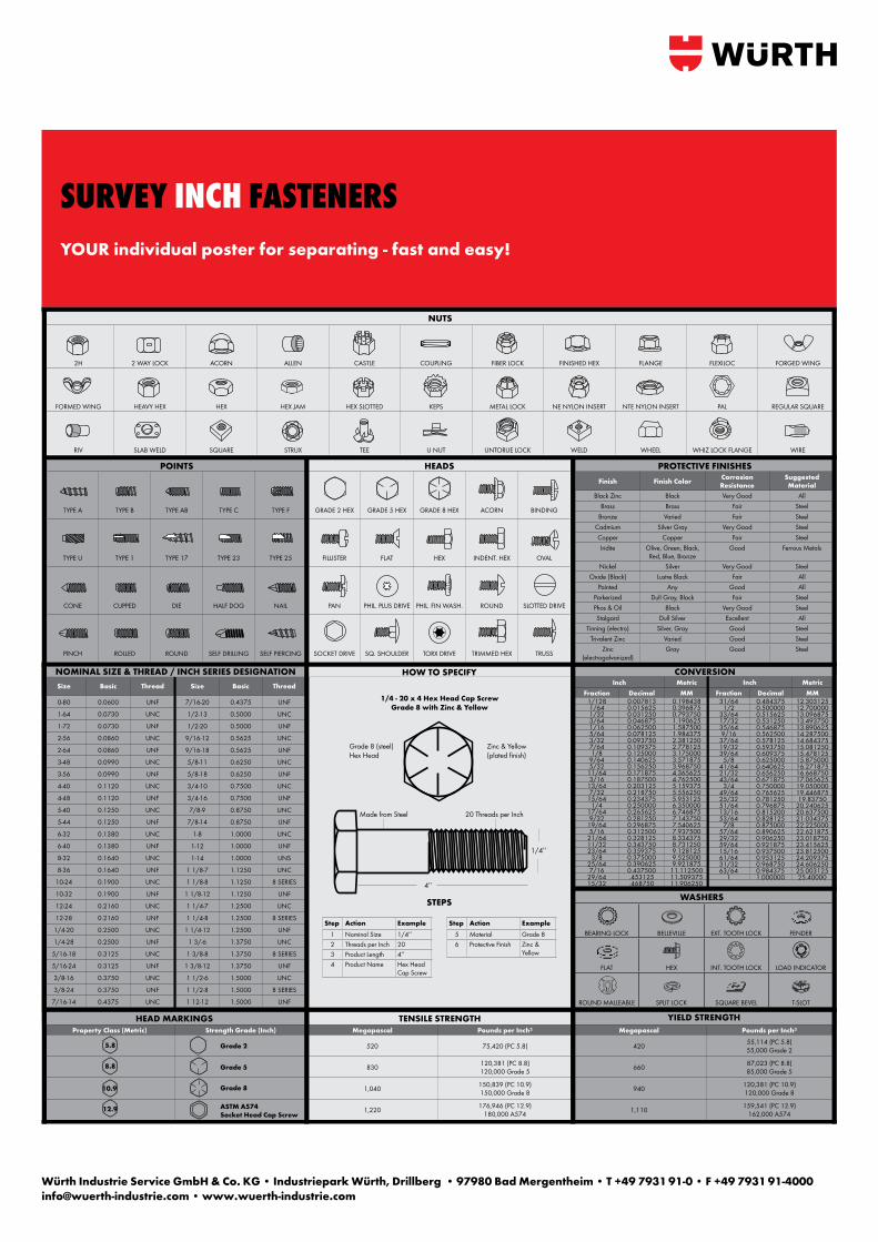
CONVERSION
HEAD MARKINGS
NUTS
2H 2 WAY LOCK ACORN ALLEN CASTLE COUPLING FIBER LOCK FINISHED HEX FLANGE FLEXILOC FORGED WING
FORMED WING HEAVY HEX HEX HEX JAM HEX SLOTTED KEPS METAL LOCK NE NYLON INSERT NTE NYLON INSERT PAL REGULAR SQUARE
RIV SLAB WELD SQUARE STRUX TEE U NUT UNTORUE LOCK WELD WHEEL WHIZ LOCK FLANGE WIRE
CPS®TECH - Featuring Fastener Academy: Facilitated by Würth Engineers highlighting fastener fundamentals, manufacturing processes, mechanical basics, industry standards, and other fastener modules. Enroll today!
SIMPLIFY WITH CPS®
Property Class (Metric) Strength Grade (Inch) Megapascal Pounds per Inch² Megapascal Pounds per Inch²
520 75,420 (PC 5.8) 420 55,114 (PC 5.8)55,000 Grade 2
830 120,381 (PC 8.8)120,000 Grade 5 660 87,023 (PC 8.8)
85,000 Grade 5
1,040 150,839 (PC 10.9)150,000 Grade 8 940 120,381 (PC 10.9)
120,000 Grade 8
1,220 176,946 (PC 12.9)180,000 A574 1,110 159,541 (PC 12.9)
162,000 A574
TENSILE STRENGTH YIELD STRENGTH
5.8 Grade 2
Grade 5
Grade 8
ASTM A574Socket Head Cap Screw
POINTS
TYPE A TYPE B TYPE AB TYPE C TYPE F
TYPE U TYPE 1 TYPE 17 TYPE 23 TYPE 25
CONE CUPPED DIE HALF DOG NAIL
PINCH ROLLED ROUND SELF DRILLING SELF PIERCING
HEADS
GRADE 2 HEX GRADE 5 HEX GRADE 8 HEX ACORN BINDING
FILLISTER FLAT HEX INDENT. HEX OVAL
PAN PHIL. PLUS DRIVE PHIL. FIN WASH. ROUND SLOTTED DRIVE
SOCKET DRIVE SQ. SHOULDER TORX DRIVE TRIMMED HEX TRUSS
PROTECTIVE FINISHESFinish Finish Color Corrosion
ResistanceSuggested Material
Black Zinc Black Very Good AllBrass Brass Fair Steel
Bronze Varied Fair SteelCadmium Silver Gray Very Good SteelCopper Copper Fair SteelIridite Olive, Green, Black,
Red, Blue, BronzeGood Ferrous Metals
Nickel Silver Very Good SteelOxide (Black) Lustre Black Fair All
Painted Any Good AllParkerized Dull Gray, Black Fair SteelPhos & Oil Black Very Good SteelStalgard Dull Silver Excellent All
Tinning (electro) Silver, Gray Good SteelTrivalent Zinc Varied Good Steel
Zinc (electrogalvanized)
Gray Good Steel
Size Basic Thread
0-80 0.0600 UNF
1-64 0.0730 UNC
1-72 0.0730 UNF
2-56 0.0860 UNC
2-64 0.0860 UNF
3-48 0.0990 UNC
3-56 0.0990 UNF
4-40 0.1120 UNC
4-48 0.1120 UNF
5-40 0.1250 UNC
5-44 0.1250 UNF
6-32 0.1380 UNC
6-40 0.1380 UNF
8-32 0.1640 UNC
8-36 0.1640 UNF
10-24 0.1900 UNC
10-32 0.1900 UNF
12-24 0.2160 UNC
12-28 0.2160 UNF
1/4-20 0.2500 UNC
1/4-28 0.2500 UNF
5/16-18 0.3125 UNC
5/16-24 0.3125 UNF
3/8-16 0.3750 UNC
3/8-24 0.3750 UNF
7/16-14 0.4375 UNC
Size Basic Thread
7/16-20 0.4375 UNF
1/2-13 0.5000 UNC
1/2-20 0.5000 UNF
9/16-12 0.5625 UNC
9/16-18 0.5625 UNF
5/8-11 0.6250 UNC
5/8-18 0.6250 UNF
3/4-10 0.7500 UNC
3/4-16 0.7500 UNF
7/8-9 0.8750 UNC
7/8-14 0.8750 UNF
1-8 1.0000 UNC
1-12 1.0000 UNF
1-14 1.0000 UNS
1 1/8-7 1.1250 UNC
1 1/8-8 1.1250 8 SERIES
1 1/8-12 1.1250 UNF
1 1/4-7 1.2500 UNC
1 1/4-8 1.2500 8 SERIES
1 1/4-12 1.2500 UNF
1 3/-6 1.3750 UNC
1 3/8-8 1.3750 8 SERIES
1 3/8-12 1.3750 UNF
1 1/2-6 1.5000 UNC
1 1/2-8 1.5000 8 SERIES
1 12-12 1.5000 UNF
Inch MetricFraction Decimal MM
31/64 0.484375 12.3031251/2 0.500000 12.700000
33/64 0.515625 13.09687517/32 0.531250 13.49375035/64 0.546875 13.8906259/16 0.562500 14.287500
37/64 0.578125 14.68437519/32 0.593750 15.08125039/64 0.609375 15.478125
5/8 0.625000 15.87500041/64 0.640625 16.27187521/32 0.656250 16.66875043/64 0.671875 17.065625
3/4 0.750000 19.05000049/64 0.765625 19.44687525/32 0.781250 19.8375051/64 0.796875 20.24062513/16 0.815200 20.63750053/64 0.828125 21.034375
7/8 0.875000 22.22500057/64 0.890625 22.62187529/32 0.906250 23.01875059/64 0.921875 23.41562515/16 0.937500 23.81250061/64 0.953125 24.20937531/32 0.968750 24.60625063/64 0.984375 25.003125
1 1.000000 25.40000
Inch MetricFraction Decimal MM
1/128 0.007813 0.1984381/64 0.015625 0.3968751/32 0.031250 0.7937503/64 0.046875 1.1906251/16 0.062500 1.5875005/64 0.078125 1.9843753/32 0.093750 2.3812507/64 0.109375 2.7781251/8 0.125000 3.175000
9/64 0.140625 3.5718755/32 0.156250 3.968750
11/64 0.171875 4.3656253/16 0.187500 4.762500
13/64 0.203125 5.1593757/32 0.218750 5.556250
15/64 0.234375 5.9531251/4 0.250000 6.350000
17/64 0.265625 6.7468759/32 0.281250 7.143750
19/64 0.296875 7.5406255/16 0.312500 7.937500
21/64 0.328125 8.33437511/32 0.343750 8.73125023/64 0.359375 9.128125
3/8 0.375000 9.52500025/64 0.390625 9.9218757/16 0.437500 11.112500
29/64 .453125 11.50937515/32 .468750 11.906250
1/4 - 20 x 4 Hex Head Cap ScrewGrade 8 with Zinc & Yellow
Grade 8 (steel) Hex Head
Zinc & Yellow (plated fi nish)
Step Action Example1 Nominal Size 1/4’’2 Threads per Inch 203 Product Length 4’’4 Product Name Hex Head
Cap Screw
Step Action Example5 Material Grade 86 Protective Finish Zinc &
Yellow
Made from Steel 20 Threads per Inch
4’’
1/4’’
NOMINAL SIZE & THREAD / INCH SERIES DESIGNATION HOW TO SPECIFY
STEPS
8.8
10.9
12.9
WASHERS
BEARING LOCK BELLEVILLE EXT. TOOTH LOCK FENDER
FLAT HEX INT. TOOTH LOCK LOAD INDICATOR
ROUND MALLEABLE SPLIT LOCK SQUARE BEVEL T-SLOT
SURVEY Inch FastenersYOUR individual poster for separating - fast and easy!
Würth Industrie Service GmbH & Co. KG • Industriepark Würth, Drillberg • 97980 Bad Mergentheim • T +49 7931 91-0 • F +49 7931 91-4000 [email protected] • www.wuerth-industrie.com
INCH FASTENERS
Printed on environmentally friendly paper.
We reserve the right to make any changes we deem necessary to improve the quality of the product, even without prior announcement or notification. Illustrations can be sample illustrations that may differ in appearance from the goods supplied. Errors excepted. We do not ac-cept any liability for misprints. Our general terms and conditions apply.
Printed in Germany. All rights reserved.Responsible for the Content / Editors:D. Lange/E; T. Giera/TPA; C. Schimanowski/MPPicture: A. Triscoiu/ADesign: A. Hoffmann/MW
Reproduction, in whole or in part, is prohibited without the prior permission of the copyright owner.
MW – Schweikert – AH – 1’ – 02/14
Würth Industrie Service GmbH & Co. KGIndustriepark Würth, Drillberg 97980 Bad Mergentheim, GermanyT +49 7931 91-0F +49 7931 [email protected]
© Würth Industrie Service GmbH & Co. KG