bolts, screws, nuts, and washers 18.2.1 1996.pdf · dard ansi/asme b18.2.1-1996 and for nuts from...
TRANSCRIPT

1492 BOLTS AND NUTS
BOLTS, SCREWS, NUTS, AND WASHERS
Dimensions of bolts, screws, nuts, and washers used in machine construction are givenhere. For data on thread forms, see Square and Hex Bolts, Screws, and Nuts in “ScrewThread Systems” section.
American Square and Hexagon Bolts, Screws, and Nuts.—The 1941 American Stan-dard ASA B18.2 covered head dimensions only. In 1952 and 1955 the Standard wasrevised to cover the entire product. Some bolt and nut classifications were simplified byelimination or consolidation in agreements reached with the British and Canadians. In1965 ASA B18.2 was redesignated into two standards: B18.2.1 covering square and hexa-gon bolts and screws including hexagon cap screws and lag screws and B18.2.2 coveringsquare and hexagon nuts. In B18.2.1-1965, hexagon head cap screws and finished hexagonbolts were consolidated into a single product heavy semifinished hexagon bolts and heavyfinished hexagon bolts were consolidated into a single product; regular semifinished hexa-gon bolts were eliminated; a new tolerance pattern for all bolts and screws and a positiveidentification procedure for determining whether an externally threaded product should bedesignated as a bolt or screw were established. Also included in this standard are heavyhexagon bolts and heavy hexagon structural bolts. In B18.2.2-1965, regular semifinishednuts were discontinued; regular hexagon and heavy hexagon nuts in sizes 1⁄4 through 1 inch,finished hexagon nuts in sizes larger than 11⁄2 inches, washer-faced semifinished style offinished nuts in sizes 5⁄8-inch and smaller and heavy series nuts in sizes 7⁄16-inch and smallerwere eliminated.
Further revisions and refinements include the addition of askew head bolts and hex headlag screws and the specifying of countersunk diameters for the various hex nuts. Heavy hexstructural bolts and heavy hex nuts were moved to a new structural applications standard.Additionally, B18.2.1 has been revised to allow easier conformance to Public Law 101-592. All these changes are reflected in ANSI/ASME B18.2.1-1996, and ANSI/ASMEB18.2.2-1987 (R1999).
Unified Square and Hexagon Bolts, Screws, and Nuts.—Items that are recognized inthe Standard as “unified” dimensionally with British and Canadian standards are shown inbold-face in certain tables.
The other items in the same tables are based on formulas accepted and published by theBritish for sizes outside the ranges listed in their standards which, as a matter of informa-tion, are BS 1768:1963 (obsolescent) for Precision (Normal Series) Unified HexagonBolts, Screws, Nuts (UNC and UNF Threads) and B.S. 1769 and amendments for Black(Heavy Series) Unified Hexagon Bolts, etc. Tolerances applied to comparable dimensionsof American and British Unified bolts and nuts may differ because of rounding off prac-tices and other factors.
Differentiation between Bolt and Screw.—A bolt is an externally threaded fastenerdesigned for insertion through holes in assembled parts, and is normally intended to betightened or released by torquing a nut.
A screw is an externally threaded fastener capable of being inserted into holes in assem-bled parts, of mating with a preformed internal thread or forming its own thread and ofbeing tightened or released by torquing the head.
An externally threaded fastener which is prevented from being turned during assembly,and which can be tightened or released only by torquing a nut is a bolt. (Example: roundhead bolts, track bolts, plow bolts.)
An externally threaded fastener that has a thread form which prohibits assembly with anut having a straight thread of multiple pitch length is a screw. (Example: wood screws,tapping screws.)

BOLTS AND NUTS 1493
An externally threaded fastener that must be assembled with a nut to perform its intendedservice is a bolt. (Example: heavy hex structural bolt.)
An externally threaded fastener that must be torqued by its head into a tapped or otherpreformed hole to perform its intended service is a screw. (Example: square head setscrew.)
Square and Hex Bolts, Screws, and Nuts.—The dimensions for square and hex boltsand screws given in the following tables have been taken from American National Stan-dard ANSI/ASME B18.2.1-1996 and for nuts from American National StandardANSI/ASME B18.2.2-1987 (R1999) Reference should be made to these Standards forinformation or data not found in the following text and tables:
Designation: Bolts and screws should be designated by the following data in thesequence shown: nominal size (fractional and decimal equivalent); threads per inch (omitfor lag screws); product length for bolts and screws (fractional or two-place decimal equiv-alent); product name; material, including specification, where necessary; and protective
Square Bolts( Table 1 )
Heavy Hex Structural Bolts ( Table 2 )Hex Nuts ( Table 7 )
Heavy Hex Nuts (Table 7)
Hex Bolts, Heavy Hex Bolts (Table 3 )Hex Jam Nuts (Table 7)
Heavy Hex Jam Nuts (Table 7)
Hex Cap Screws, Heavy Hex Screws (Table 4)

1494 BOLTS AND NUTS
finish, if required. Examples: (1) 3⁄8-16 × 11⁄2 Square Bolt, Steel, Zinc Plated; (2) 1⁄2-13 × 3Hex Cap Screw, SAE Grade 8 Steel; and (3) .75 × 5.00 Hex Lag Screw, Steel. (4) 1⁄2-13Square Nut, Steel, Zinc Plated; (5) 3⁄4-16 Heavy Hex Nut, SAE J995 Grade 5 Steel; and (6)1000-8 Hex Thick Slotted Nut, ASTM F594 (Alloy Group 1) Corrosion-Resistant Steel.
All dimensions are in inches. Bold type shows bolts unified dimensionally with British andCanadian Standards. Threads, when rolled, shall be Unified Coarse, Fine, or 8-thread series(UNRC, UNRF, or 8 UNR Series), Class 2A. Threads produced by other methods may be UnifiedCoarse, Fine, or 8-thread series (UNC, UNF, or 8 UN Series), Class 2A.
Table 1. American National Standard and Unified Standard Square Bolts ANSI/ASME B18.2.1-1996
SQUARE BOLTS
NominalSizea or BasicProduct Dia.
a Where specifying nominal size in decimals, zeros before the decimal point and in the fourth deci-mal place are omitted.
BodyDia.bE
b See Body Diameter footnote in Table 3.
Width AcrossFlats F
Width AcrossCorners G
Head HeightH
ThreadLengthc LT
c Thread lengths, LT, shown are for bolt lengths 6 inches and shorter. For longer bolt lengths add0.250 inch to thread lengths shown.
Max. Basic Max. Min. Max. Min. Basic Max. Min. Nom.1⁄⁄⁄⁄4 0.2500 0.260 3⁄⁄⁄⁄8 0.375 0.362 0.530 0.498 11⁄⁄⁄⁄64 0.188 0.156 0.750
5⁄⁄⁄⁄16 0.3125 0.324 1⁄⁄⁄⁄2 0.500 0.484 0.707 0.665 13⁄⁄⁄⁄64 0.220 0.186 0.875
3⁄⁄⁄⁄8 0.3750 0.388 9⁄⁄⁄⁄16 0.562 0.544 0.795 0.747 1⁄⁄⁄⁄4 0.268 0.232 1.000
7⁄⁄⁄⁄16 0.4375 0.452 5⁄⁄⁄⁄8 0.625 0.603 0.884 0.828 19⁄⁄⁄⁄64 0.316 0.278 1.125
1⁄⁄⁄⁄2 0.5000 0.515 3⁄⁄⁄⁄4 0.750 0.725 1.061 0.995 21⁄⁄⁄⁄64 0.348 0.308 1.250
5⁄⁄⁄⁄8 0.6250 0.642 15⁄⁄⁄⁄16 0.938 0.906 1.326 1.244 27⁄⁄⁄⁄64 0.444 0.400 1.500
3⁄⁄⁄⁄4 0.7500 0.768 11⁄⁄⁄⁄8 1.125 1.088 1.591 1.494 1⁄⁄⁄⁄2 0.524 0.476 1.750
7⁄⁄⁄⁄8 0.8750 0.895 15⁄⁄⁄⁄16 1.312 1.269 1.856 1.742 19⁄⁄⁄⁄32 0.620 0.568 2.000
1 1.0000 1.022 11⁄⁄⁄⁄2 1.500 1.450 2.121 1.991 21⁄⁄⁄⁄32 0.684 0.628 2.250
11⁄⁄⁄⁄8 1.1250 1.149 111⁄⁄⁄⁄16 1.688 1.631 2.386 2.239 3⁄⁄⁄⁄4 0.780 0.720 2.500
11⁄⁄⁄⁄4 1.2500 1.277 17⁄⁄⁄⁄8 1.875 1.812 2.652 2.489 27⁄⁄⁄⁄32 0.876 0.812 2.750
13⁄⁄⁄⁄8 1.3750 1.404 21⁄⁄⁄⁄16 2.602 1.994 2.917 2.738 29⁄⁄⁄⁄32 0.940 0.872 3.000
11⁄⁄⁄⁄2 1.5000 1.531 21⁄⁄⁄⁄4 2.250 2.175 3.182 2.986 1 1.036 0.964 3.250
Table 2. American National Standard Heavy Hex Structural Bolts ANSI/ASME B18.2.1-1981 (R1992)a
a Heavy hex structural bolts have been removed from the latest version, ANSI/ASME B18.2.1-1996.The table has been included for reference.
HEAVY HEX STRUCTURAL BOLTS
Nominal Sizea
or BasicProduct Dia.
BodyDia.E
WidthAcrossFlats F
Width AcrossCorners G
HeightH
Radiusof Fillet
RThrd.
Lgth.LT
Transi-tion
Thrd.Y
Max. Min. Max. Min. Max. Min. Max. Min. Max. Min. Basic Max.
1⁄2 0.5000 0.515 0.482 0.875 0.850 1.010 0.969 0.323 0.302 0.031 0.009 1.00 0.19
5⁄8 0.6250 0.642 0.605 1.062 1.031 1.227 1.175 0.403 0.378 0.062 0.021 1.25 0.22
3⁄4 0.7500 0.768 0.729 1.250 1.212 1.443 1.383 0.483 0.455 0.062 0.021 1.38 0.25
7⁄8 0.8750 0.895 0.852 1.438 1.394 1.660 1.589 0.563 0.531 0.062 0.031 1.50 0.28
1 1.0000 1.022 0.976 1.625 1.575 1.876 1.796 0.627 0.591 0.093 0.062 1.75 0.31
11⁄8 1.1250 1.149 1.098 1.812 1.756 2.093 2.002 0.718 0.658 0.093 0.062 2.00 0.34
11⁄4 1.2500 1.277 1.223 2.000 1.938 2.309 2.209 0.813 0.749 0.093 0.062 2.00 0.38
13⁄8 1.3750 1.404 1.345 2.188 2.119 2.526 2.416 0.878 0.810 0.093 0.062 2.25 0.44
11⁄2 1.5000 1.531 1.470 2.375 2.300 2.742 2.622 0.974 0.902 0.093 0.062 2.25 0.44

BOLTS AND NUTS 1495
All dimensions are in inches.Bold type shows bolts unified dimensionally with British and Canadian Standards.
Threads: Threads, when rolled, are Unified Coarse, Fine, or 8-thread series (UNRC, UNRF, or 8UNR Series), Class 2A. Threads produced by other methods may be Unified Coarse, Fine or 8-threadseries (UNC, UNF, or 8 UN Series), Class 2A.
Body Diameter: Bolts may be obtained in “reduced diameter body.” Where “reduced diameterbody” is specified, the body diameter may be reduced to approximately the pitch diameter of thethread. A shoulder of full body diameter under the head may be supplied at the option of the manu-facturer.
Material: Unless otherwise specified, chemical and mechanical properties of steel bolts conformto ASTM A307, Grade A. Other materials are as agreed upon by manufacturer and purchaser.
Table 3. American National Standard and Unified Standard Hex and Heavy Hex Bolts ANSI/ASME B18.2.1-1996
NominalSizea or Basic
Dia.
a Nominal Size: Where specifying nominal size in decimals, zeros preceding the decimal point andin the fourth decimal place are omitted.
Full SizeBody Dia.E
Width AcrossFlats F
Width AcrossCorners G
Head HeightH
ThreadLengthb LT
b Thread lengths, LT, shown are for bolt lengths 6 inches and shorter. For longer bolt lengths add0.250 inch to thread lengths shown.
Max. Basic Max. Min. Max. Min. Basic Max. Min. Nom.HEX BOLTS
1⁄⁄⁄⁄4 0.2500 0.260 7⁄⁄⁄⁄16 0.438 0.425 0.505 0.484 11⁄⁄⁄⁄64 0.188 0.150 0.7505⁄⁄⁄⁄16 0.3125 0.324 1⁄⁄⁄⁄2 0.500 0.484 0.577 0.552 7⁄⁄⁄⁄32 0.235 0.195 0.8753⁄⁄⁄⁄8 0.3750 0.388 9⁄⁄⁄⁄16 0.562 0.544 0.650 0.620 1⁄⁄⁄⁄4 0.268 0.226 1.0007⁄⁄⁄⁄16 0.4375 0.452 5⁄⁄⁄⁄8 0.625 0.603 0.722 0.687 19⁄⁄⁄⁄64 0.316 0.272 1.1251⁄⁄⁄⁄2 0.5000 0.515 3⁄⁄⁄⁄4 0.750 0.725 0.866 0.826 11⁄⁄⁄⁄32 0.364 0.302 1.2505⁄⁄⁄⁄8 0.6250 0.642 15⁄⁄⁄⁄16 0.938 0.906 1.083 1.033 27⁄⁄⁄⁄64 0.444 0.378 1.5003⁄⁄⁄⁄4 0.7500 0.768 11⁄⁄⁄⁄8 1.125 1.088 1.299 1.240 1⁄⁄⁄⁄2 0.524 0.455 1.7507⁄⁄⁄⁄8 0.8750 0.895 15⁄⁄⁄⁄16 1.312 1.269 1.516 1.447 37⁄⁄⁄⁄64 0.604 0.531 2.000
1 1.0000 1.022 11⁄⁄⁄⁄2 1.500 1.450 1.732 1.653 43⁄⁄⁄⁄64 0.700 0.591 2.250
11⁄⁄⁄⁄8 1.1250 1.149 111⁄⁄⁄⁄16 1.688 1.631 1.949 1.859 3⁄⁄⁄⁄4 0.780 0.658 2.500
11⁄⁄⁄⁄4 1.2500 1.277 17⁄⁄⁄⁄8 1.875 1.812 2.165 2.066 27⁄⁄⁄⁄32 0.876 0.749 2.750
13⁄⁄⁄⁄8 1.3750 1.404 21⁄⁄⁄⁄16 2.062 1.994 2.382 2.273 29⁄⁄⁄⁄32 0.940 0.810 3.000
11⁄⁄⁄⁄2 1.5000 1.531 21⁄⁄⁄⁄4 2.250 2.175 2.598 2.480 1 1.036 0.902 3.250
13⁄⁄⁄⁄4 1.7500 1.785 25⁄⁄⁄⁄8 2.625 2.538 3.031 2.893 15⁄⁄⁄⁄32 1.196 1.054 3.7502 2.000 2.039 3 3.000 2.900 3.464 3.306 111⁄⁄⁄⁄32 1.388 1.175 4.250
21⁄4 2.2500 2.305 33⁄8 3.375 3.262 3.897 3.719 11⁄2 1.548 1.327 4.750
21⁄2 2.5000 2.559 33⁄4 3.750 3.625 4.330 4.133 121⁄32 1.708 1.479 5.250
23⁄4 2.7500 2.827 41⁄8 4.125 3.988 4.763 4.546 113⁄16 1.869 1.632 5.7503 3.0000 3.081 41⁄2 4.500 4.350 5.196 4.959 2 2.060 1.815 6.250
31⁄4 3.2500 3.335 47⁄8 4.875 4.712 5.629 5.372 23⁄16 2.251 1.936 6.750
31⁄2 3.5000 3.589 51⁄4 5.250 5.075 6.062 5.786 25⁄16 2.380 2.057 7.250
33⁄4 3.7500 3.858 55⁄8 5.625 5.437 6.495 6.198 21⁄2 2.572 2.241 7.7504 4.0000 4.111 6 6.000 5.800 6.928 6.612 211⁄16 2.764 2.424 8.250
HEAVY HEX BOLTS
1⁄⁄⁄⁄2 0.5000 0.515 7⁄⁄⁄⁄8 0.875 0.850 1.010 0.969 11⁄32 0.364 0.302 1.2505⁄⁄⁄⁄8 0.6250 0.642 11⁄⁄⁄⁄16 1.062 1.031 1.227 1.175 27⁄64 0.444 0.378 1.5003⁄⁄⁄⁄4 0.7500 0.768 11⁄⁄⁄⁄4 1.250 1.212 1.443 1.383 1⁄2 0.524 0.455 1.7507⁄⁄⁄⁄8 0.8750 0.895 17⁄⁄⁄⁄16 1.438 1.394 1.660 1.589 37⁄64 0.604 0.531 2.000
1 1.0000 1.022 15⁄⁄⁄⁄8 1.625 1.575 1.876 1.796 43⁄64 0.700 0.591 2.250
11⁄⁄⁄⁄8 1.1250 1.149 113⁄⁄⁄⁄16 1.812 1.756 2.093 2.002 3⁄4 0.780 0.658 2.500
11⁄⁄⁄⁄4 1.2500 1.277 2 2.000 1.938 2.309 2.209 27⁄32 0.876 0.749 2.750
13⁄⁄⁄⁄8 1.3750 1.404 23⁄⁄⁄⁄16 2.188 2.119 2.526 2.416 29⁄32 0.940 0.810 3.000
11⁄⁄⁄⁄2 1.5000 1.531 23⁄⁄⁄⁄8 23.75 2.300 2.742 2.622 1 1.036 0.902 3.250
13⁄⁄⁄⁄4 1.7500 1.785 23⁄⁄⁄⁄4 2.750 2.662 3.175 3.035 15⁄32 1.196 1.054 3.7502 2.0000 2.039 31⁄8 3.125 3.025 3.608 3.449 111⁄32 1.388 1.175 4.250
21⁄4 2.2500 2.305 31⁄2 3.500 3.388 4.041 3.862 11⁄2 1.548 1.327 4.750
21⁄2 2.5000 2.559 37⁄8 3.875 3.750 4.474 4.275 121⁄32 1.708 1.479 5.250
23⁄4 2.7500 2.827 41⁄4 4.250 4.112 4.907 4.688 113⁄16 1.869 1.632 5.7503 3.0000 3.081 45⁄8 4.625 4.475 5.340 5.102 2 2.060 1.815 6.250

1496 BOLTS AND NUTS
Table 4. American National Standard and Unified Standard Heavy Hex Screws and Hex Cap Screws ANSI/ASME B18.2.1-1996
All dimensions are in inches.Unification: Bold type indicates product features unified dimensionally with British and
Canadian Standards. Unification of fine thread products is limited to sizes 1 inch and smaller.Bearing Surface: Bearing surface is flat and washer faced. Diameter of bearing surface is equal to
the maximum width across flats within a tolerance of minus 10 per cent. Threads Series: Threads, when rolled, are Unified Coarse, Fine, or 8-thread series (UNRC, UNRF,
or 8 UNR Series), Class 2A. Threads produced by other methods shall preferably be UNRC, UNRFor 8 UNR but, at manufacturer's option, may be Unified Coarse, Fine or 8-thread series (UNC, UNF,or 8 UN Series), Class 2A.
Material: Chemical and mechanical properties of steel screws normally conform to Grades 2, 5, or8 of SAE J429, ASTM A449 or ASTM A354 Grade BD. Where specified, screws may also be madefrom brass, bronze, corrosion-resisting steel, aluminum alloy or other materials.
Nominal Sizea
or BasicProduct Dia.
a Nominal Size: Where specifying nominal size in decimals, zeros preceding the decimal and in thefourth decimal place are omitted.
Body Dia.E
Width AcrossFlats F
Width AcrossCorners G
HeightH
ThreadLengthbLT
b Thread lengths, LT, shown are for bolt lengths 6 inches and shorter. For longer bolt lengths add0.250 inch to thread lengths shown.
Max. Min. Basic Max. Min. Max. Min. Basic Max. Min. Basic
HEAVY HEX SCREWS
1⁄⁄⁄⁄2 0.5000 0.5000 0.482 7⁄⁄⁄⁄8 0.875 .0850 1.010 0.969 5⁄16 0.323 0.302 1.2505⁄⁄⁄⁄8 0.6250 0.6250 0.605 11⁄⁄⁄⁄16 1.062 1.031 1.227 1.175 25⁄64 0.403 0.378 1.5003⁄⁄⁄⁄4 0.7500 0.7500 0.729 11⁄⁄⁄⁄4 1.250 1.212 1.443 1.383 15⁄32 0.483 0.455 1.7507⁄⁄⁄⁄8 0.8750 0.8750 0.852 17⁄⁄⁄⁄16 1.438 1.394 1.660 1.589 35⁄64 0.563 0.531 2.000
1 1.0000 1.0000 0.976 15⁄⁄⁄⁄8 1.625 1.575 1.876 1.796 39⁄64 0.627 0.591 2.250
11⁄⁄⁄⁄8 1.1250 1.1250 1.098 113⁄⁄⁄⁄16 1.812 1.756 2.093 2.002 11⁄16 0.718 0.658 2.500
11⁄⁄⁄⁄4 1.2500 1.2500 1.223 2 2.000 1.938 2.309 2.209 25⁄32 0.813 0.749 2.750
13⁄⁄⁄⁄8 1.3750 1.3750 1.345 23⁄⁄⁄⁄16 2.188 2.119 2.526 2.416 27⁄32 0.878 0.810 3.000
11⁄⁄⁄⁄2 1.5000 1.5000 1.470 23⁄⁄⁄⁄8 2.375 2.300 2.742 2.622 15⁄16 0.974 0.902 3.250
13⁄⁄⁄⁄4 1.7500 1.7500 1.716 23⁄⁄⁄⁄4 2.750 2.662 3.175 3.035 13⁄32 1.134 1.054 3.750
2 2.0000 2.0000 1.964 31⁄⁄⁄⁄8 3.125 3.025 3.608 3.449 17⁄32 1.263 1.175 4.250
21⁄4 2.2500 2.2500 2.214 31⁄2 3.500 3.388 4.041 3.862 13⁄8 1.423 1.327 5.000c
c Thread lengths, LT, shown are for bolt lengths over 6 inches.
21⁄2 2.5000 2.5000 2.461 37⁄8 3.875 3.750 4.474 4.275 117⁄32 1.583 1.479 5.500c
23⁄4 2.7500 2.7500 2.711 41⁄4 4.250 41.112 4.907 4.688 111⁄16 1.744 1.632 6.000c
3 3.0000 3.0000 2.961 45⁄8 4.625 4.475 5.340 5.102 17⁄8 1.935 1.815 6.500c
HEX CAP SCREWS (Finished Hex Bolts)
1⁄⁄⁄⁄4 0.2500 0.2500 0.2450 7⁄⁄⁄⁄16 0.438 0.428 0.505 0.488 5⁄⁄⁄⁄32 0.163 0.150 0.7505⁄⁄⁄⁄16 0.3125 0.3125 0.3065 1⁄⁄⁄⁄2 0.500 0.489 0.577 0.557 13⁄⁄⁄⁄64 0.211 0.195 0.8753⁄⁄⁄⁄8 0.3750 0.3750 0.3690 9⁄⁄⁄⁄16 0.562 0.551 0.650 0.628 15⁄⁄⁄⁄64 0.243 0.226 1.0007⁄⁄⁄⁄16 0.4375 0.4375 0.4305 5⁄⁄⁄⁄8 0.625 0.612 0.722 0.698 9⁄⁄⁄⁄32 0.291 0.272 1.1251⁄⁄⁄⁄2 0.5000 0.5000 0.4930 3⁄⁄⁄⁄4 0.750 0.736 0.866 0.840 5⁄⁄⁄⁄16 0.323 0.302 1.2509⁄⁄⁄⁄16 0.5625 0.5625 0.5545 13⁄⁄⁄⁄16 0.812 0.798 0.938 0.910 23⁄⁄⁄⁄64 0.371 0.348 1.3755⁄⁄⁄⁄8 0.6250 0.6250 0.6170 15⁄⁄⁄⁄16 0.938 0.922 1.083 1.051 25⁄⁄⁄⁄64 0.403 0.378 1.5003⁄⁄⁄⁄4 0.7500 0.7500 0.7410 11⁄⁄⁄⁄8 1.125 1.100 1.299 1.254 15⁄⁄⁄⁄32 0.483 0.455 1.7507⁄⁄⁄⁄8 0.8750 0.8750 0.8660 15⁄⁄⁄⁄16 1.312 1.285 1.516 1.465 35⁄⁄⁄⁄64 0.563 0.531 2.000
1 1.0000 1.0000 0.9900 11⁄⁄⁄⁄2 1.500 1.469 1.732 1.675 39⁄⁄⁄⁄64 0.627 0.591 2.250
11⁄⁄⁄⁄8 1.1250 1.1250 1.1140 111⁄⁄⁄⁄16 1.688 1.631 1.949 1.859 11⁄⁄⁄⁄16 0.718 0.658 2.500
11⁄⁄⁄⁄4 1.2500 1.2500 1.2390 17⁄⁄⁄⁄8 1.875 1.812 2.165 2.066 25⁄⁄⁄⁄35 0.813 0.749 2.750
13⁄⁄⁄⁄8 1.3750 1.3750 1.3630 21⁄⁄⁄⁄16 2.062 1.994 2.382 2.273 27⁄⁄⁄⁄32 0.878 0.810 3.000
11⁄⁄⁄⁄2 1.5000 1.5000 1.4880 21⁄⁄⁄⁄4 2.250 2.175 2.598 2.480 15⁄⁄⁄⁄16 0.974 0.902 3.250
13⁄⁄⁄⁄4 1.7500 1.7500 1.7380 25⁄⁄⁄⁄8 2.625 2.538 3.031 2.893 13⁄⁄⁄⁄32 1.134 1.054 3.750
2 2.0000 2.0000 1.9880 3 3.000 2.900 3.464 3.30617⁄⁄⁄⁄32 1.263 1.175 4.250
21⁄4 2.2500 2.2500 2.2380 33⁄8 3.375 3.262 3.897 3.719 13⁄8 1.423 1.327 5.000c
21⁄2 2.5000 2.5000 2.4880 33⁄4 3.750 3.625 4.330 4.133 117⁄32 1.583 1.479 5.500c
23⁄4 2.7500 2.7500 2.7380 41⁄8 4.125 3.988 4.763 4.546 111⁄16 1.744 1.632 6.000c
3 3.0000 3.0000 2.9880 41⁄2 4.500 4.350 5.196 4.959 17⁄8 1.935 1.815 6.500c

BO
LT
S AN
D N
UT
S1497
All dimensions in inches.
Minimum thread length is 1⁄2 length of screw plus 0.50 inch, or 6.00 inches, whichever is shorter. Screws too short for the formula thread length shall be threaded asclose to the head as practicable.
Thread formulas: Pitch = 1 ÷ thds. per inch. Flat at root = 0.4305 × pitch. Depth of single thread = 0.385 × pitch.
Table 5. American National Standard Square Lag Screws ANSI/ASME B18.2.1-1996
Nominal Sizea
or BasicProduct
Dia.
a When specifying decimal nominal size, zeros before decimal point and in fourth decimal place are omitted.
Body orShoulder
Dia. E
Width AcrossFlats
F
Width AcrossCorners
GHeight
H
ShoulderLength
S
Radiusof Fillet
R
Thds.per
Inch Thread Dimensions
Max. Min. Basic Max. Min. Max. Min. Basic Max. Min. Min. Max.Pitch
PFlat atRoot B
Depth of Thd.T
RootDia.D1
No. 10 0.1900 0.199 0.178 9⁄32 0.281 0.271 0.398 0.372 1⁄8 0.140 0.110 0.094 0.03 11 0.091 0.039 0.035 0.1201⁄4 0.2500 0.260 0.237 3⁄8 0.375 0.362 0.530 0.498 11⁄64 0.188 0.156 0.094 0.03 10 0.100 0.043 0.039 0.1735⁄16 0.3125 0.324 0.298 1⁄2 0.500 0.484 0.707 0.665 13⁄64 0.220 0.186 0.125 0.03 9 0.111 0.048 0.043 0.2273⁄8 0.3750 0.388 0.360 9⁄16 0.562 0.544 0.795 0.747 1⁄4 0.268 0.232 0.125 0.03 7 0.143 0.062 0.055 0.2657⁄16 0.4375 0.452 0.421 5⁄8 0.625 0.603 0.884 0.828 19⁄64 0.316 0.278 0.156 0.03 7 0.143 0.062 0.055 0.3281⁄2 0.5000 0.515 0.482 3⁄4 0.750 0.725 1.061 0.995 21⁄64 0.348 0.308 0.156 0.03 6 0.167 0.072 0.064 0.3715⁄8 0.6250 0.642 0.605 15⁄16 0.938 0.906 1.326 1.244 27⁄64 0.444 0.400 0.312 0.06 5 0.200 0.086 0.077 0.4713⁄4 0.7500 0.768 0.729 11⁄8 1.125 1.088 1.591 1.494 1⁄2 0.524 0.476 0.375 0.06 41⁄2 0.222 0.096 0.085 0.5797⁄8 0.8750 0.895 0.852 15⁄16 1.312 1.269 1.856 1.742 19⁄42 0.620 0.568 0.375 0.06 4 0.250 0.108 0.096 0.683
1 1.0000 1.022 0.976 11⁄2 1.500 1.450 2.121 1.991 21⁄32 0.684 0.628 0.625 0.09 31⁄2 0.286 0.123 0.110 0.780
11⁄8 1.1250 1.149 1.098 111⁄16 1.688 1.631 2.386 2.239 3⁄4 0.780 0.720 0.625 0.09 31⁄4 0.308 0.133 0.119 0.887
11⁄4 1.2500 1.277 1.223 17⁄8 1.875 1.812 2.652 2.489 27⁄32 0.876 0.812 0.625 0.09 31⁄4 0.308 0.133 0.119 1.012

BO
LT
S AN
D N
UT
S1498
All dimensions in inches.
Minimum thread length is 1⁄2 length of screw plus 0.50 inch, or 6.00 inches, whichever is shorter. Screws too short for the formula thread length shall be threaded asclose to the head as practicable.
Thread formulas: Pitch = 1 ÷ thds. per inch. Flat at root = 0.4305 × pitch. Depth of single thread = 0.385 × pitch.
Table 6. American National Standard Hex Lag Screws ANSI/ASME B18.2.1-1996
Nominal Sizea
or Basic Product Dia.
a When specifying decimal nominal size, zeros before decimal point and in fourth decimal place are omitted.
Body orShoulder Dia.
EWidth Across Flats
F
Width Across Cor-nersG
HeightH
ShoulderLength
S
Radiusof Fillet
R Thds.per
Inch
Thread Dimensions
Max. Min. Basic Max. Min. Max. Min. Basic Max. Min. Min. Max.Pitch
PFlat at Root
BDepth of Thd.
TRoot Dia.
D1
No. 10 0.1900 0.199 0.178 9⁄32 0.281 0.271 0.323 0.309 1⁄8 0.140 0.110 0.094 0.03 11 0.091 0.039 0.035 0.1201⁄4 0.2500 0.260 0.237 3⁄8 0.438 0.425 0.505 0.484 11⁄64 0.188 0.150 0.094 0.03 10 0.100 0.043 0.039 0.1735⁄16 0.3125 0.324 0.298 1⁄2 0.500 0.484 0.577 0.552 7⁄32 0.235 0.195 0.125 0.03 9 0.111 0.048 0.043 0.2273⁄8 0.3750 0.388 0.360 9⁄16 0.562 0.544 0.650 0.620 1⁄4 0.268 0.226 0.125 0.03 7 0.143 0.062 0.055 0.2657⁄16 0.4375 0.452 0.421 5⁄8 0.625 0.603 0.722 0.687 19⁄64 0.316 0.272 0.156 0.03 7 0.143 0.062 0.055 0.3281⁄2 0.5000 0.515 0.482 3⁄4 0.750 0.725 0.866 0.826 11⁄32 0.364 0.302 0.156 0.03 6 0.167 0.072 0.064 0.3715⁄8 0.6250 0.642 0.605 15⁄16 0.938 0.906 1.083 1.033 27⁄64 0.444 0.378 0.312 0.06 5 0.200 0.086 0.077 0.4713⁄4 0.7500 0.768 0.729 11⁄8 1.125 1.088 1.299 1.240 1⁄2 0.524 0.455 0.375 0.06 41⁄2 0.222 0.096 0.085 0.5797⁄8 0.8750 0.895 0.852 15⁄16 1.312 1.269 1.516 1.447 37⁄64 0.604 0.531 0.375 0.06 4 0.250 0.108 0.096 0.683
1 1.0000 1.022 0.976 11⁄2 1.500 1.450 1.732 1.653 43⁄64 0.700 0.591 0.625 0.09 31⁄2 0.286 0.123 0.110 0.780
11⁄8 1.1250 1.149 1.098 111⁄16 1.688 1.631 1.949 1.859 3⁄4 0.780 0.658 0.625 0.09 31⁄4 0.308 0.133 0.119 0.887
11⁄4 1.2500 1.277 1.223 17⁄8 1.875 1.812 2.165 2.066 27⁄32 0.876 0.749 0.625 0.09 31⁄4 0.308 0.133 0.119 1.012

BOLTS AND NUTS 1499
All dimensions are in inches.
Bold type shows nuts unified dimensionally with British and Canadian Standards.
Threads are Unified Coarse-, Fine-, or 8-thread series (UNC, UNF or 8UN), Class 2B. Unificationof fine-thread nuts is limited to sizes 1 inch and under.
Table 7. American National Standard and Unified Standard Hex Nuts and Jam Nuts and Heavy Hex Nuts and Jam ANSI/ASME B18.2.2-1987 (R1999)
Nominal Size or Basic
Major Dia. of Thread
Width Across Flats F
Width AcrossCorners G
Thickness, NutsH
Thickness,Jam NutsH1
Basic Max. Min. Max. Min. Basic Max. Min. Basic Max. Min.
Hex Nuts and Hex Jam Nuts
1⁄⁄⁄⁄4 0.2500 7⁄⁄⁄⁄16 0.438 0.428 0.505 0.488 7⁄⁄⁄⁄32 0.226 0.212 5⁄⁄⁄⁄32 0.163 0.150
5⁄⁄⁄⁄16 0.3125 1⁄⁄⁄⁄2 0.500 0.489 0.577 0.557 17⁄⁄⁄⁄64 0.273 0.258 3⁄⁄⁄⁄16 0.195 0.180
3⁄⁄⁄⁄8 0.3750 9⁄⁄⁄⁄16 0.562 0.551 0.650 0.628 21⁄⁄⁄⁄64 0.337 0.320 7⁄⁄⁄⁄32 0.227 0.210
7⁄⁄⁄⁄16 0.4375 11⁄⁄⁄⁄16 0.688 0.675 0.794 0.768 3⁄⁄⁄⁄8 0.385 0.365 1⁄⁄⁄⁄4 0.260 0.240
1⁄⁄⁄⁄2 0.5000 3⁄⁄⁄⁄4 0.750 0.736 0.866 0.840 7⁄⁄⁄⁄16 0.448 0.427 5⁄⁄⁄⁄16 0.323 0.302
9⁄⁄⁄⁄16 0.5625 7⁄⁄⁄⁄8 0.875 0.861 1.010 0.982 31⁄⁄⁄⁄64 0.496 0.473 5⁄⁄⁄⁄16 0.324 0.301
5⁄⁄⁄⁄8 0.6250 15⁄⁄⁄⁄16 0.938 0.922 1.083 1.051 35⁄⁄⁄⁄64 0.559 0.535 3⁄⁄⁄⁄8 0.387 0.363
3⁄⁄⁄⁄4 0.7500 11⁄⁄⁄⁄8 1.125 1.088 1.299 1.240 41⁄⁄⁄⁄64 0.665 0.617 27⁄⁄⁄⁄64 0.446 0.398
7⁄⁄⁄⁄8 0.8750 15⁄⁄⁄⁄16 1.312 1.269 1.516 1.447 3⁄⁄⁄⁄4 0.776 0.724 31⁄⁄⁄⁄64 0.510 0.458
1 1.0000 11⁄⁄⁄⁄2 1.500 1.450 1.732 1.653 55⁄⁄⁄⁄64 0.887 0.831 35⁄⁄⁄⁄64 0.575 0.519
11⁄⁄⁄⁄8 1.1250 111⁄⁄⁄⁄16 1.688 1.631 1.949 1.859 31⁄⁄⁄⁄32 0.999 0.939 39⁄⁄⁄⁄64 0.639 0.579
11⁄⁄⁄⁄4 1.2500 17⁄⁄⁄⁄8 1.875 1.812 2.165 2.066 11⁄⁄⁄⁄16 1.094 1.030 23⁄⁄⁄⁄32 0.751 0.687
13⁄⁄⁄⁄8 1.3750 21⁄⁄⁄⁄16 2.062 1.994 2.382 2.273 111⁄⁄⁄⁄64 1.206 1.138 25⁄⁄⁄⁄32 0.815 0.747
11⁄⁄⁄⁄2 1.5000 21⁄⁄⁄⁄4 2.250 2.175 2.598 2.480 19⁄⁄⁄⁄32 1.317 1.245 27⁄⁄⁄⁄32 0.880 0.808
Heavy Hex Nuts and Heavy Hex Jam Nuts
1⁄4 0.2500 1⁄2 0.500 0.488 0.577 0.556 15⁄64 0.250 0.218 11⁄64 0.188 0.156
5⁄16 0.3125 9⁄16 0.562 0.546 0.650 0.622 19⁄64 0.314 0.280 13⁄64 0.220 0.186
3⁄8 0.3750 11⁄16 0.688 0.669 0.794 0.763 23⁄64 0.377 0.341 15⁄64 0.252 0.216
7⁄16 0.4375 3⁄4 0.750 0.728 0.866 0.830 27⁄64 0.441 0.403 17⁄64 0.285 0.247
1⁄⁄⁄⁄2 0.5000 7⁄⁄⁄⁄8 0.875 0.850 1.010 0.969 31⁄⁄⁄⁄64 0.504 0.464 19⁄⁄⁄⁄64 0.317 0.277
9⁄16 0.5625 15⁄16 0.938 0.909 1.083 1.037 35⁄64 0.568 0.526 21⁄64 0.349 0.307
5⁄⁄⁄⁄8 0.6250 11⁄⁄⁄⁄16 1.062 1.031 1.227 1.1175 39⁄⁄⁄⁄64 0.631 0.587 23⁄⁄⁄⁄64 0.381 0.337
3⁄⁄⁄⁄4 0.7500 11⁄⁄⁄⁄4 1.250 1.212 1.443 1.382 47⁄⁄⁄⁄64 0.758 0.710 27⁄⁄⁄⁄64 0.446 0.398
7⁄⁄⁄⁄8 0.8750 17⁄⁄⁄⁄16 1.438 1.394 1660 1.589 55⁄⁄⁄⁄64 0.885 0.833 31⁄⁄⁄⁄64 0.510 0.458
1 1.0000 15⁄8 1.625 1.575 1.876 1.796 63⁄⁄⁄⁄64 1.012 0.956 35⁄⁄⁄⁄64 0.575 0.519
11⁄⁄⁄⁄8 1.1250 113⁄⁄⁄⁄16 1.812 1.756 2.093 2.002 17⁄⁄⁄⁄64 1.139 1.079 39⁄⁄⁄⁄64 0.639 0.579
11⁄⁄⁄⁄4 1.2500 2 2.000 1.938 2.309 2.209 17⁄⁄⁄⁄32 1.251 1.187 23⁄⁄⁄⁄32 0.751 0.687
13⁄⁄⁄⁄8 1.3750 23⁄⁄⁄⁄16 2.188 2.119 2.526 2.416 111⁄⁄⁄⁄32 1.378 1.310 25⁄⁄⁄⁄32 0.815 0.747
11⁄⁄⁄⁄2 1.5000 23⁄⁄⁄⁄8 2.375 2.300 2.742 2.622 115⁄⁄⁄⁄32 1.505 1.433 27⁄⁄⁄⁄32 0.880 0.808
15⁄8 1.6250 29⁄16 2.562 2.481 2.959 2.828 119⁄32 1.632 1.556 29⁄32 0.944 0.868
13⁄⁄⁄⁄4 1.7500 23⁄⁄⁄⁄4 2.750 2.662 3.175 3.035 123⁄⁄⁄⁄32 1.759 1.679 31⁄⁄⁄⁄32 1.009 0.929
17⁄8 1.8750 215⁄16 2.938 2.844 3.392 3.242 127⁄32 1.886 1.802 11⁄32 1.073 0.989
2 2.0000 31⁄⁄⁄⁄8 3.125 3.025 3.608 3.449 131⁄⁄⁄⁄32 2.013 1.925 13⁄⁄⁄⁄32 1.138 1.050
21⁄4 2.2500 31⁄2 3.500 3.388 4.041 3.862 213⁄64 2.251 2.155 113⁄64 1.251 1.155
21⁄2 2.5000 37⁄8 3.875 3.750 4.474 4.275 229⁄64 2.505 2.401 129⁄64 1.505 1.401
23⁄4 2.7500 41⁄4 4.250 4.112 4.907 4.688 245⁄64 2.759 2.647 137⁄64 1.634 1.522
3 3.0000 45⁄8 4.625 4.475 5.340 5.102 261⁄64 3.013 2.893 145⁄64 1.763 1.643
31⁄4 3.2500 5 5.000 4.838 5.774 5.515 33⁄16 3.252 3.124 113⁄16 1.876 1.748
31⁄2 3.5000 53⁄8 5.375 5.200 6.207 5.928 37⁄16 3.506 3.370 115⁄16 2.006 1.870
33⁄4 3.7500 53⁄4 5.750 5.562 6.640 6.341 311⁄16 3.760 3.616 21⁄16 2.134 1.990
4 4.0000 61⁄8 6.125 5.925 7.073 6.755 315⁄16 4.014 3.862 23⁄16 2.264 2.112

1500 BOLTS AND NUTS
Table 8. American National Standard and Unified Standard Hex Flat Nuts and Flat Jam Nuts and Heavy Hex Flat Nuts and Flat Jam Nuts
ANSI/ASME B18.2.2-1987 (R1999)
All dimensions are in inches.Bold type indicates nuts unified dimensionally with British and Canadian Standards.Threads are Unified Coarse-thread series (UNC), Class 2B.
NominalSize or
Basic MajorDia. of Thread
WidthAcrossFlatsF
WidthAcrossCornersG
Thickness,Flat NutsH
Thickness,Flat Jam NutsH1
Basic Max. Min. Max. Min. Basic Max. Min. Basic Max. Min.
Hex Flat Nuts and Hex Flat Jam Nuts
11⁄⁄⁄⁄8 1.1250 111⁄⁄⁄⁄16 1.688 1.631 1.949 1.859 1 1.030 0.970 5⁄⁄⁄⁄8 0.655 0.595
11⁄⁄⁄⁄4 1.2500 17⁄⁄⁄⁄8 1.875 1.812 2.165 2.066 13⁄⁄⁄⁄32 1.126 1.062 3⁄⁄⁄⁄4 0.782 0.718
13⁄⁄⁄⁄8 1.3750 21⁄⁄⁄⁄16 2.062 1.994 2.382 2.273 113⁄⁄⁄⁄64 1.237 1.169 13⁄⁄⁄⁄16 0.846 0.778
11⁄⁄⁄⁄2 1.5000 21⁄⁄⁄⁄4 2.250 2.175 2.598 2.480 15⁄⁄⁄⁄16 1.348 1.276 7⁄⁄⁄⁄8 0.911 0.839
Heavy Hex Flat Nuts and Heavy Hex Flat Jam Nuts
11⁄⁄⁄⁄8 1.1250 113⁄⁄⁄⁄16 1.812 1.756 2.093 2.002 11⁄⁄⁄⁄8 1.155 1.079 5⁄⁄⁄⁄8 0.655 0.579
11⁄⁄⁄⁄4 1.2500 2 2.000 1.938 2.309 2.209 11⁄⁄⁄⁄4 1.282 1.187 3⁄⁄⁄⁄4 0.782 0.687
13⁄⁄⁄⁄8 1.3750 23⁄⁄⁄⁄16 2.188 2.119 2.526 2.416 13⁄⁄⁄⁄8 1.409 1.310 13⁄⁄⁄⁄16 0.846 0.747
11⁄⁄⁄⁄2 1.5000 23⁄⁄⁄⁄8 2.375 2.300 2.742 2.622 11⁄⁄⁄⁄2 1.536 1.433 7⁄⁄⁄⁄8 0.911 0.808
13⁄⁄⁄⁄4 1.7500 23⁄⁄⁄⁄4 2.750 2.662 3.175 3.035 13⁄⁄⁄⁄4 1.790 1.679 1 1.040 0.929
2 2.0000 31⁄⁄⁄⁄8 3.125 3.025 3.608 3.449 2 2.044 1.925 11⁄⁄⁄⁄8 1.169 1.050
21⁄4 2.2500 31⁄2 3.500 3.388 4.041 3.862 21⁄4 2.298 2.155 11⁄4 1.298 1.155
21⁄2 2.5000 37⁄8 3.875 3.750 4.474 4.275 21⁄2 2.552 2.401 11⁄2 1.552 1.401
23⁄4 2.7500 41⁄4 4.250 4.112 4.907 4.688 23⁄4 2.806 2.647 15⁄8 1.681 1.522
3 3.0000 45⁄8 4.625 4.475 5.340 5.102 3 3.060 2.893 13⁄4 1.810 1.643
31⁄4 3.2500 5 5.000 4.838 5.774 5.515 31⁄4 3.314 3.124 17⁄8 1.939 1.748
31⁄2 3.5000 53⁄8 5.375 5.200 6.207 5.928 31⁄2 3.568 3.370 2 2.068 1.870
33⁄4 3.7500 53⁄4 5.750 5.562 6.640 6.341 33⁄4 3.822 3.616 21⁄8 2.197 1.990
4 4.0000 61⁄8 6.125 5.925 7.073 6.755 4 4.076 3.862 21⁄4 2.326 2.112
Hex Slotted Nuts (Table 9)Heavy Hex Slotted Nuts (Table 9)Hex Thick Slotted Nuts (Table9)
Square Nuts Heavy Square Nuts(Table 10)
Hex Thick Nuts(Table 10 )
Hex Flat Nuts (Table 8)Heavy Hex Flat Nuts (Table 8)Hex Flat Jam Nuts (Table 8)
Heavy Hex Flat Jam Nuts (Table 8)

BOLTS AND NUTS 1501
All dimensions are in inches.Bold type indicates nuts unified dimensionally with British and Canadian Standards.Threads are Unified Coarse-, Fine-, or 8-thread series (UNC, UNF, or 8UN), Class 2B.Unification of fine-thread nuts is limited to sizes 1 inch and under.
Table 9. American National and Unified Standard Hex Slotted Nuts, Heavy Hex Slotted Nuts, and Hex Thick Slotted Nuts ANSI/ASME B18.2.2-1987 (R1999)
Nominal Size orBasic Major
Dia. of Thread
Width AcrossFlats F
Width AcrossCorners G
ThicknessH
UnslottedThickness T
Width of SlotS
Basic Max. Min. Max. Min. Basic Max. Min. Max. Min. Max. Min.
Hex Slotted Nuts1⁄⁄⁄⁄4 0.2500 7⁄⁄⁄⁄16 0.438 0.428 0.505 0.488 7⁄⁄⁄⁄32 0.226 0.212 0.14 0.12 0.10 0.075⁄⁄⁄⁄16 0.3125 1⁄⁄⁄⁄2 0.500 0.489 0.577 0.577 17⁄⁄⁄⁄64 0.273 0.258 0.18 0.16 0.12 0.093⁄⁄⁄⁄8 0.3750 9⁄⁄⁄⁄16 0.562 0.551 0.650 0.628 21⁄⁄⁄⁄64 0.337 0.320 0.21 0.19 0.15 0.127⁄⁄⁄⁄16 0.4375 11⁄⁄⁄⁄16 0.688 0.675 0.794 0.768 3⁄⁄⁄⁄8 0.385 0.365 0.23 0.21 0.15 0.121⁄⁄⁄⁄2 0.5000 3⁄⁄⁄⁄4 0.750 0.736 0.866 0.840 7⁄⁄⁄⁄16 0.448 0.427 0.29 0.27 0.18 0.159⁄⁄⁄⁄16 0.5625 7⁄⁄⁄⁄8 0.875 0.861 1.010 0.982 31⁄⁄⁄⁄64 0.496 0.473 0.31 0.29 0.18 0.155⁄⁄⁄⁄8 0.6250 15⁄⁄⁄⁄16 0.938 0.922 1.083 1.051 35⁄⁄⁄⁄64 0.559 0.535 0.34 0.32 0.24 0.183⁄⁄⁄⁄4 0.7500 11⁄⁄⁄⁄8 1.125 1.088 1.299 1.240 41⁄⁄⁄⁄64 0.665 0.617 0.40 0.38 0.24 0.187⁄⁄⁄⁄8 0.8750 15⁄⁄⁄⁄16 1.312 1.269 1.516 1.447 3⁄⁄⁄⁄4 0.776 0.724 0.52 0.49 0.24 0.18
1 1.0000 11⁄⁄⁄⁄2 1.500 1.450 1.732 1.653 55⁄⁄⁄⁄64 0.887 0.831 0.59 0.56 0.30 0.2411⁄⁄⁄⁄8 1.1250 111⁄⁄⁄⁄16 1.688 1.631 1.949 1.859 31⁄⁄⁄⁄32 0.999 0.939 0.64 0.61 0.33 0.24
11⁄⁄⁄⁄4 1.2500 17⁄⁄⁄⁄8 1.875 1.812 2.165 2.066 11⁄⁄⁄⁄16 1.094 1.030 0.70 0.67 0.40 0.3113⁄⁄⁄⁄8 1.3750 21⁄⁄⁄⁄16 2.062 1.994 2.382 2.273 111⁄⁄⁄⁄64 1.206 1.138 0.82 0.78 0.40 0.31
11⁄⁄⁄⁄2 1.5000 21⁄⁄⁄⁄4 2.250 2.175 2.598 2.480 19⁄⁄⁄⁄32 1.317 1.245 0.86 0.82 0.46 0.37
Heavy Hex Slotted Nuts1⁄4 0.2500 1⁄2 0.500 0.488 0.577 0.556 15⁄64 0.250 0.218 0.15 0.13 0.10 0.075⁄16 0.3125 9⁄16 0.562 0.546 0.650 0.622 19⁄64 0.314 0.280 0.21 0.19 0.12 0.093⁄8 0.3750 11⁄16 0.688 0.669 0.794 0.763 23⁄64 0.377 0.341 0.24 0.22 0.15 0.127⁄16 0.4375 3⁄4 0.750 0.728 0.866 0.830 27⁄64 0.441 0.403 0.28 0.26 0.15 0.121⁄⁄⁄⁄2 0.5000 7⁄⁄⁄⁄8 0.875 0.850 1.010 0.969 31⁄⁄⁄⁄64 0.504 0.464 0.34 0.32 0.18 0.159⁄16 0.5625 15⁄16 0.938 0.909 1.083 1.037 35⁄64 0.568 0.526 0.37 0.35 0.18 0.155⁄⁄⁄⁄8 0.6250 11⁄⁄⁄⁄16 1.062 1.031 1.227 1.175 39⁄⁄⁄⁄64 0.631 0.587 0.40 0.38 0.24 0.183⁄⁄⁄⁄4 0.7500 11⁄⁄⁄⁄4 1.250 1.212 1.443 1.382 47⁄⁄⁄⁄64 0.758 0.710 0.49 0.47 0.24 0.187⁄⁄⁄⁄8 0.8750 17⁄⁄⁄⁄16 1.438 1.394 1.660 1.589 55⁄⁄⁄⁄64 0.885 0.833 0.62 0.59 0.24 0.18
1 1.0000 15⁄⁄⁄⁄8 1.625 1.575 1.876 1.796 63⁄⁄⁄⁄64 1.012 0.956 0.72 0.69 0.30 0.24
11⁄⁄⁄⁄8 1.1250 113⁄⁄⁄⁄16 1.812 1.756 2.093 2.002 17⁄⁄⁄⁄64 1.139 1.079 0.78 0.75 0.33 0.24
11⁄⁄⁄⁄4 1.2500 2 2.000 1.938 2.309 2.209 17⁄⁄⁄⁄32 1.251 1.187 0.86 0.83 0.40 0.31
13⁄⁄⁄⁄8 1.3750 23⁄⁄⁄⁄16 2.188 2.119 2.526 2.416 111⁄⁄⁄⁄32 1.378 1.310 0.99 0.95 0.40 0.31
11⁄⁄⁄⁄2 1.5000 23⁄⁄⁄⁄8 2.375 2.300 2.742 2.622 115⁄⁄⁄⁄32 1.505 1.433 1.05 1.01 0.46 0.37
13⁄⁄⁄⁄4 1.7500 23⁄⁄⁄⁄4 2.750 2.662 3.175 3.035 123⁄⁄⁄⁄32 1.759 1.679 1.24 1.20 0.52 0.432 2.0000 31⁄⁄⁄⁄8 3.125 3.025 3.608 3.449 131⁄⁄⁄⁄32 2.013 1.925 1.43 1.38 0.52 0.43
21⁄4 2.2500 31⁄2 3.500 3.388 4.041 3.862 213⁄64 2.251 2.155 1.67 1.62 0.52 0.43
21⁄2 2.5000 37⁄8 3.875 3.750 4.474 4.275 229⁄64 2.505 2.401 1.79 1.74 0.64 0.55
23⁄4 2.7500 41⁄4 4.250 4.112 4.907 4.688 245⁄64 2.759 2.647 2.05 1.99 0.64 0.553 3.0000 45⁄8 4.625 4.475 5.340 5.102 261⁄64 3.013 2.893 2.23 2.17 0.71 0.62
31⁄4 3.2500 5 5.000 4.838 5.774 5.515 33⁄16 3.252 3.124 2.47 2.41 0.71 0.62
31⁄2 3.5000 53⁄8 5.375 5.200 6.207 5.928 37⁄16 3.506 3.370 2.72 2.65 0.71 0.62
33⁄4 3.7500 53⁄4 5.750 5.562 6.640 6.341 311⁄16 3.760 3.616 2.97 2.90 0.71 0.624 4.0000 61⁄8 6.125 5.925 7.073 6.755 315⁄16 4.014 3.862 3.22 3.15 0.71 0.62
Hex Thick Slotted Nuts1⁄⁄⁄⁄4 0.2500 7⁄⁄⁄⁄16 0.438 0.428 0.505 0.488 9⁄⁄⁄⁄32 0.288 0.274 0.20 0.18 0.10 0.075⁄⁄⁄⁄16 0.3125 1⁄⁄⁄⁄2 0.500 0.489 0.577 0.557 21⁄⁄⁄⁄64 0.336 0.320 0.24 0.22 0.12 0.093⁄⁄⁄⁄8 0.3750 9⁄⁄⁄⁄16 0.562 0.551 0.650 0.628 13⁄⁄⁄⁄32 0.415 0.398 0.29 0.27 0.15 0.127⁄⁄⁄⁄16 0.4375 11⁄⁄⁄⁄16 0.688 0.675 0.794 0.768 29⁄⁄⁄⁄24 0.463 0.444 0.31 0.29 0.15 0.121⁄⁄⁄⁄2 0.5000 3⁄⁄⁄⁄4 0.750 0.736 0.866 0.840 9⁄⁄⁄⁄16 0.573 0.552 0.42 0.40 0.18 0.159⁄⁄⁄⁄16 0.5625 7⁄⁄⁄⁄8 0.875 0.861 1.010 0.982 39⁄⁄⁄⁄64 0.621 0.598 0.43 0.41 0.18 0.155⁄⁄⁄⁄8 0.6250 15⁄⁄⁄⁄16 0.938 0.922 1.083 1.051 23⁄⁄⁄⁄32 0.731 0.706 0.51 0.49 0.24 0.183⁄⁄⁄⁄4 0.7500 11⁄⁄⁄⁄8 1.125 1.088 1.299 1.240 13⁄⁄⁄⁄16 0.827 0.798 0.57 0.55 0.24 0.187⁄⁄⁄⁄8 0.8750 15⁄⁄⁄⁄16 1.312 1.269 1.516 1.447 29⁄⁄⁄⁄32 0.922 0.890 0.67 0.64 0.24 0.18
1 1.0000 11⁄⁄⁄⁄2 1.500 1.450 1.732 1.653 1 1.018 0.9820.73 0.70 0.30 0.24
11⁄⁄⁄⁄8 1.1250 111⁄⁄⁄⁄16 1.688 1.631 1.949 1.859 15⁄⁄⁄⁄32 1.176 1.136 0.83 0.80 0.33 0.24
11⁄⁄⁄⁄4 1.2500 17⁄⁄⁄⁄8 1.875 1.812 2.165 2.066 11⁄⁄⁄⁄4 1.272 1.228 0.89 0.86 0.40 0.31
13⁄⁄⁄⁄8 1.3750 21⁄⁄⁄⁄16 2.062 1.994 2.382 2.273 13⁄⁄⁄⁄8 1.399 1.351 1.02 0.98 0.40 0.31
11⁄⁄⁄⁄2 1.5000 21⁄⁄⁄⁄4 2.250 2.175 2.598 2.480 11⁄⁄⁄⁄2 1.526 1.474 1.08 1.04 0.46 0.37

1502 BOLTS AND NUTS
All dimensions are in inches.Bold type indicates nuts unified dimensionally with British and Canadian Standards.
Table 10. American National and Unified Standard Square Nuts and Heavy Square Nuts and American National Standard Hex Thick Nuts
ANSI/ASME B18.2.2-1987 (R1999)
Nominal Size or Basic Major Dia.
of Thread
Width Across Flats F
Width Across Corners G
ThicknessH
Basic Max. Min. Max. Min. Basic Max. Min.Square Nutsa
a Coarse-thread series, Class 2B.
1⁄⁄⁄⁄4 0.2500 7⁄⁄⁄⁄16 0.438 0.425 0.619 0.554 7⁄⁄⁄⁄32 0.235 0.2035⁄⁄⁄⁄16 0.3125 9⁄⁄⁄⁄16 0.562 0.547 0.795 0.721 17⁄⁄⁄⁄64 0.283 0.2493⁄⁄⁄⁄8 0.3750 5⁄⁄⁄⁄8 0.625 0.606 0.884 0.802 21⁄⁄⁄⁄64 0.346 0.3107⁄⁄⁄⁄16 0.4375 3⁄⁄⁄⁄4 0.750 0.728 1.061 0.970 3⁄⁄⁄⁄8 0.394 0.3561⁄⁄⁄⁄2 0.5000 13⁄⁄⁄⁄16 0.812 0.788 1.149 1.052 7⁄⁄⁄⁄16 0.458 0.4185⁄⁄⁄⁄8 0.6250 1 1.000 0.969 1.414 35⁄⁄⁄⁄64 0.569 0.5253⁄⁄⁄⁄4 0.7500 11⁄⁄⁄⁄8 1.125 1.088 1.591 1.464 21⁄⁄⁄⁄32 0.680 0.6327⁄⁄⁄⁄8 0.8750 15⁄⁄⁄⁄16 1.312 1.269 1.856 1.712 49⁄⁄⁄⁄64 0.792 0.740
1 1.0000 11⁄⁄⁄⁄2 1.500 1.450 2.121 1.961 7⁄⁄⁄⁄8 0.903 0.847
11⁄⁄⁄⁄8 1.1250 111⁄⁄⁄⁄16 1.688 1.631 2.386 2.209 1 1.030 0.970
11⁄⁄⁄⁄4 1.2500 17⁄⁄⁄⁄8 1.875 1.812 2.652 2.458 13⁄⁄⁄⁄32 1.126 1.062
13⁄⁄⁄⁄8 1.3750 21⁄⁄⁄⁄16 2.062 1.994 2.917 2.708 113⁄⁄⁄⁄64 1.237 1.169
11⁄⁄⁄⁄2 1.5000 21⁄⁄⁄⁄4 2.250 2.175 3.182 2.956 15⁄⁄⁄⁄16 1.348 1.276
Heavy Square Nutsa
1⁄4 0.2500 1⁄2 0.500 0.488 0.707 0.640 1⁄4 0.266 0.2185⁄16 0.3125 9⁄16 0.562 0.546 0.795 0.720 5⁄16 0.330 0.2803⁄8 0.3750 11⁄16 0.688 0.669 0.973 0.889 3⁄8 0.393 0.3417⁄16 0.4375 3⁄4 0.750 0.728 1.060 0.970 7⁄16 0.456 0.4031⁄2 0.5000 7⁄8 0.875 0.850 1.237 1.137 1⁄2 0.520 0.4645⁄8 0.6250 11⁄16 1.062 1.031 1.503 1.386 5⁄8 0.647 0.5873⁄4 0.7500 11⁄4 1.250 1.212 1.768 1.635 3⁄4 0.774 0.7107⁄8 0.8750 17⁄16 1.438 1.394 2.033 1.884 7⁄8 0.901 0.833
1 1.0000 15⁄8 1.625 1.575 2.298 2.132 1 1.028 0.956
11⁄8 1.1250 113⁄16 1.812 1.756 2.563 2.381 11⁄8 1.155 1.079
11⁄4 1.2500 2 2.000 1.938 2.828 2.631 11⁄4 1.282 1.187
13⁄8 1.3750 23⁄16 2.188 2.119 3.094 2.879 13⁄8 1.409 1.310
11⁄2 1.5000 23⁄8 2.375 2.300 3.359 3.128 11⁄2 1.536 1.433
Hex Thick Nutsb
b Unified Coarse-, Fine-, or 8-thread series (8 UN), Class 2B.
1⁄4 0.2500 7⁄16 0.438 0.428 0.505 0.488 9⁄32 0.288 0.2745⁄16 0.3125 1⁄2 0.500 0.489 0.577 0.557 21⁄64 0.336 0.3203⁄8 0.3750 9⁄16 0.562 0.551 0.650 0.628 13⁄32 0.415 0.3987⁄16 0.4375 11⁄16 0.688 0.675 0.794 0.768 29⁄64 0.463 0.4441⁄2 0.5000 3⁄4 0.750 0.736 0.866 0.840 9⁄16 0.573 0.5529⁄16 0.5625 7⁄8 0.875 0.861 1.010 0.982 39⁄64 0.621 0.5985⁄8 0.6250 15⁄16 0.938 0.922 1.083 1.051 23⁄32 0.731 0.7063⁄4 0.7500 11⁄8 1.125 1.088 1.299 1.240 13⁄16 0.827 0.7987⁄8 0.8750 15⁄16 1.312 1.269 1.516 1.447 29⁄32 0.922 0.890
1 1.0000 11⁄2 1.500 1.450 1.732 1.653 1 1.018 0.982
11⁄8 1.1250 111⁄16 1.688 1.631 1.949 1.859 15⁄32 1.176 1.136
11⁄4 1.2500 17⁄8 1.875 1.812 2.165 2.066 11⁄4 1.272 1.228
13⁄8 1.3750 21⁄16 2.062 1.994 2.382 2.273 13⁄8 1.399 1.351
11⁄2 1.5000 21⁄4 2.250 2.175 2.598 2.480 11⁄2 1.526 1.474
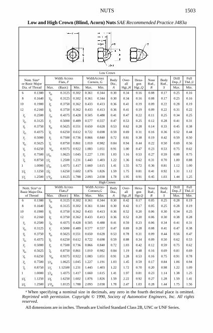
NUTS 1503
Low and High Crown (Blind, Acorn) Nuts SAE Recommended Practice J483a
All dimensions are in inches. Threads are Unified Standard Class 2B, UNC or UNF Series.
Low Crown
Nom. Sizea
or Basic MajorDia. of Thread
a When specifying a nominal size in decimals, any zero in the fourth decimal place is omitted.Reprinted with permission. Copyright © 1990, Society of Automotive Engineers, Inc. All rightsreserved.
Width AcrossFlats, F
WidthAcrossCorners, G
BodyDia.,
A
Over-all
Hgt.,H
Hexa-gon
Hgt.,Q
NoseRad.,
R
BodyRad.,
S
DrillDep.,T
FullThd.,U
Max. (Basic) Min. Max. Min. Max. Min.
6 0.1380 5⁄16 0.3125 0.302 0.361 0.344 0.30 0.34 0.16 0.08 0.17 0.25 0.16
8 0.1640 5⁄16 0.3125 0.302 0.361 0.344 0.30 0.34 0.16 0.08 0.17 0.25 0.16
10 0.1900 3⁄8 0.3750 0.362 0.433 0.413 0.36 0.41 0.19 0.09 0.22 0.28 0.19
12 0.2160 3⁄8 0.3750 0.362 0.433 0.413 0.36 0.41 0.19 0.09 0.22 0.31 0.22
1⁄4 0.2500 7⁄16 0.4375 0.428 0.505 0.488 0.41 0.47 0.22 0.11 0.25 0.34 0.25
5⁄16 0.3125 1⁄2 0.5000 0.489 0.577 0.557 0.47 0.53 0.25 0.12 0.28 0.41 0.31
3⁄8 0.3750 9⁄16 0.5625 0.551 0.650 0.628 0.53 0.62 0.28 0.14 0.33 0.45 0.38
7⁄16 0.4375 5⁄8 0.6250 0.612 0.722 0.698 0.59 0.69 0.31 0.16 0.36 0.52 0.44
1⁄2 0.5000 3⁄4 0.7500 0.736 0.866 0.840 0.72 0.81 0.38 0.19 0.42 0.59 0.50
9⁄16 0.5625 7⁄8 0.8750 0.861 1.010 0.982 0.84 0.94 0.44 0.22 0.50 0.69 0.56
5⁄8 0.6250 15⁄16 0.9375 0.922 1.083 1.051 0.91 1.00 0.47 0.23 0.53 0.75 0.62
3⁄4 0.7500 11⁄16 1.0625 1.045 1.227 1.191 1.03 1.16 0.53 0.27 0.59 0.88 0.75
7⁄8 0.8750 11⁄4 1.2500 1.231 1.443 1.403 1.22 1.36 0.62 0.31 0.70 1.00 0.88
1 1.0000 17⁄16 1.4375 1.417 1.660 1.615 1.41 1.55 0.72 0.36 0.81 1.12 1.00
11⁄8 1.1250 15⁄8 1.6250 1.602 1.876 1.826 1.59 1.75 0.81 0.41 0.92 1.31 1.12
11⁄4 1.2500 113⁄16 1.8125 1.788 2.093 2.038 1.78 1.95 0.91 0.45 1.03 1.44 1.25
High Crown
Nom. Sizea or Basic Major Dia.
of Thread
Width Across Flats,F
Width Across-Corners,G
BodyDia.,
A
Over-all
Hgt.,H
Hexa-gon
Hgt.Q
NoseRad.,
R
BodyRad.,
S
DrillDep.,T
FullThd.,U
Max. (Basic) Min. Max. Min. Max. Min.
6 0.1380 5⁄16 0.3125 0.302 0.361 0.344 0.30 0.42 0.17 0.05 0.25 0.28 0.19
8 0.1640 5⁄16 0.3125 0.302 0.361 0.344 0.30 0.42 0.17 0.05 0.25 0.28 0.19
10 0.1900 3⁄8 0.3750 0.362 0.433 0.413 0.36 0.52 0.20 0.06 0.30 0.34 0.25
12 0.2160 3⁄8 0.3750 0.362 0.433 0.413 0.36 0.52 0.20 0.06 0.30 0.38 0.28
1⁄4 0.2500 7⁄16 0.4375 0.428 0.505 0.488 0.41 0.59 0.23 0.06 0.34 0.41 0.31
5⁄16 0.3125 1⁄2 0.5000 0.489 0.577 0.557 0.47 0.69 0.28 0.08 0.41 0.47 0.38
3⁄8 0.3750 9⁄16 0.5625 0.551 0.650 0.628 0.53 0.78 0.31 0.09 0.44 0.56 0.47
7⁄16 0.4375 5⁄8 0.6250 0.612 0.722 0.698 0.59 0.88 0.34 0.09 0.50 0.62 0.53
1⁄2 0.5000 3⁄4 0.7500 0.736 0.866 0.840 0.72 1.03 0.42 0.12 0.59 0.75 0.62
9⁄16 0.5625 7⁄8 0.8750 0.861 1.010 0.982 0.84 1.19 0.48 0.16 0.69 0.81 0.69
5⁄8 0.6250 15⁄16 0.9375 0.922 1.083 1.051 0.91 1.28 0.53 0.16 0.75 0.91 0.78
3⁄4 0.7500 11⁄16 1.0625 1.045 1.227 1.191 1.03 1.45 0.59 0.17 0.84 1.06 0.94
7⁄8 0.8750 11⁄4 1.12500 1.231 1.443 1.403 1.22 1.72 0.70 0.20 0.98 1.22 1.09
1 1.0000 17⁄16 1.4375 1.417 1.660 1.615 1.41 1.97 0.81 0.23 1.14 1.38 1.25
11⁄8 1.1250 15⁄8 1.6250 1.602 1.876 1.826 1.59 2.22 0.92 0.27 1.28 1.59 1.41
11⁄4 1.2500 113⁄16 1.8125 1.788 2.093 2.038 1.78 2.47 1.03 0.28 1.44 1.75 1.56

1504 NUTS
Hex High and Hex Slotted High Nuts SAE Standard J482a
All dimensions are in inches. Threads are Unified Standard Class 2B, UNC or UNF Series.
Nominal Sizea
or Basic MajorDiameter of Thread
a When specifying a nominal size in decimals, any zero in the fourth decimal place is omitted.Reprinted with permission. Copyright © 1990, Society of Automotive Engineers, Inc. All rightsreserved.
Width Across Flats, F Width Across Corners, G Slot Width,S
Basic Max. Min. Max. Min. Min. Max.
1⁄4 0.2500 7⁄16 0.4375 0.428 0.505 0.488 0.07 0.10
5⁄16 0.3125 1⁄2 0.5000 0.489 0.577 0.557 0.09 0.12
3⁄8 0.3750 9⁄16 0.5625 0.551 0.650 0.628 0.12 0.15
7⁄16 0.4375 11⁄16 0.6875 0.675 0.794 0.768 0.12 0.15
1⁄2 0.5000 3⁄4 0.7500 0.736 0.866 0.840 0.15 0.18
9⁄16 0.5625 7⁄8 0.8750 0.861 1.010 0.982 0.15 0.18
5⁄8 0.6250 15⁄16 0.9375 0.922 1.083 1.051 0.18 0.24
3⁄4 0.7500 11⁄8 1.1250 1.088 1.299 1.240 0.18 0.24
7⁄8 0.8750 15⁄16 1.3125 1.269 1.516 1.447 0.18 0.24
1 1.0000 11⁄2 1.5000 1.450 1.732 1.653 0.24 0.30
11⁄8 1.1250 111⁄16 1.6875 1.631 1.949 1.859 0.24 0.33
11⁄4 1.2500 17⁄8 1.8750 1.812 2.165 2.066 0.31 0.40
Nominal Sizea
or Basic MajorDiameter of Thread
Thickness,H
UnslottedThickness,T
Counterbore(Optional)
Basic Max. Min. Max. Min. Dia., A Depth, D
1⁄4 0.2500 3⁄8 0.382 0.368 0.29 0.27 0.266 0.062
5⁄16 0.3125 29⁄64 0.461 0.445 0.37 0.35 0.328 0.078
3⁄8 0.3750 1⁄2 0.509 0.491 0.38 0.36 0.391 0.094
7⁄16 0.4375 39⁄64 0.619 0.599 0.46 0.44 0.453 0.109
1⁄2 0.5000 21⁄32 0.667 0.645 0.51 0.49 0.516 0.125
9⁄16 0.5625 49⁄64 0.778 0.754 0.59 0.57 0.594 0.141
5⁄8 0.6250 27⁄32 0.857 0.831 0.63 0.61 0.656 0.156
3⁄4 0.7500 1 1.015 0.985 0.76 0.73 0.781 0.188
7⁄8 0.8750 15⁄32 1.172 1.140 0.92 0.89 0.906 0.219
1 1.0000 15⁄16 1.330 1.292 1.05 1.01 1.031 0.250
11⁄8 1.1250 11⁄2 1.520 1.480 1.18 1.14 1.156 0.281
11⁄4 1.2500 111⁄16 1.710 1.666 1.34 1.29 1.281 0.312

ROUND HEAD BOLTS 1505
American National Standard Round Head and Round Head Square Neck Bolts ANSI/ASME B18.5 –1990
All dimensions are in inches unless otherwise specified.Threads are Unified Standard, Class 2A, UNC Series, in accordance with ANSI B1.1. For threads
with additive finish, the maximum diameters of Class 2A shall apply before plating or coating,whereas the basic diameters (Class 2A maximum diameters plus the allowance) shall apply to a boltafter plating or coating.
Bolts are designated in the sequence shown: nominal size (number, fraction or decimal equiva-lent); threads per inch; nominal length (fraction or decimal equivalent); product name; material; andprotective finish, if required.
i.e.:1⁄2-13 × 3 Round Head Square Neck Bolt, Steel .375-16 × 2.50 Step Bolt, Steel, Zinc Plated
All dimensions are given in inches.
Nomi-nalSize
BodyDia., E
Dia.of Head,
A
Heightof Head,
H
FilletRad.,
R
Width ofSquare,
O
Depth ofSquare,
P
CornerRad. on
Square, Q
Max. Min. Max. Min. Max. Min. Max. Max. Min. Max. Min. Max.
No. 10 0.199 .182 .469 .438 .114 .094 .031 .199 .185 .125 .094 .0311⁄4 0.260 .237 .594 .563 .145 .125 .031 .260 .245 .156 .125 .0315⁄16 0.324 .298 .719 .688 .176 .156 .031 .324 .307 .187 .156 .0313⁄8 0.388 .360 .844 .782 .208 .188 .031 .388 .368 .219 .188 .0477⁄16 0.452 .421 .969 .907 .239 .219 .031 .452 .431 .250 .219 .0471⁄2 0.515 .483 1.094 1.032 .270 .250 .031 .515 .492 .281 .250 .0475⁄8 0.642 .605 1.344 1.219 .344 .313 .062 .642 .616 .344 .313 .0783⁄4 0.768 .729 1.594 1.469 .406 .375 .062 .768 .741 .406 .375 .0787⁄8 0.895 .852 1.844 1.719 .469 .438 .062 .895 .865 .469 .438 .094
1 1.022 .976 2.094 1.969 .531 .500 .062 1.022 .990 .531 .500 .094
American National Standard T-Head Bolts ANSI/ASME B18.5 –1990
Nom. Sizea or Basic Bolt Dia.
a Where specifying nominal size in decimals, zeros preceding the decimal point and in the fourthdecimal place are omitted. For information as to threads and method of bolt designation, see footnotesto preceding table.
BodyDia., E
HeadLength, A
HeadWidth, B
HeadHeight, H
HeadRad., K
FilletRad., R
Max. Min. Max. Min. Max. Min. Max. Min. Basic Max.1⁄4 0.2500 .260 .237 .500 .488 .280 .245 .204 .172 .438 .0315⁄16 0.3125 .324 .298 .625 .609 .342 .307 .267 .233 .500 .0313⁄8 0.3750 .388 .360 .750 .731 .405 .368 .331 .295 .625 .0317⁄16 0.4375 .452 .421 .875 .853 .468 .431 .394 .356 .875 .0311⁄2 0.5000 .515 .483 1.000 .975 .530 .492 .458 .418 .875 .0315⁄8 0.6250 .642 .605 1.250 1.218 .675 .616 .585 .541 1.062 .0623⁄4 0.7500 .768 .729 1.500 1.462 .800 .741 .649 .601 1.250 .0627⁄8 0.8750 .895 .852 1.750 1.706 .938 .865 .776 .724 1.375 .062
1 1.0000 1.022 .976 2.000 1.950 1.063 .990 .903 .847 1.500 .062

1506 ROUND HEAD BOLTS
All dimensions are given in inches.Threads are Unified Standard, Class 2A, UNC Series, in accordance with ANSI B1.1. For threads
with additive finish, the maximum diameters of Class 2A apply before plating or coating, whereasthe basic diameters (Class 2A maximum diameters plus the allowance) apply to a bolt after plating orcoating.
Bolts are designated in the sequence shown: nominal size (number, fraction or decimal equiva-lent); threads per inch; nominal length (fraction or decimal equivalent); product name; material; andprotective finish, if required.
i.e.,1⁄2-13 × 3 Round Head Short Square Neck Bolt, Steel .375-16 × 2.50 Round Head Short SquareNeck Bolt, Steel, Zinc Plated
All dimensions are given in inches unless otherwise specified.*Maximum fillet radius R is 0.031 inch for all sizes.For information as to threads and method of bolt designation, see foonotes to the preceding table.
American National Standard Round Head Short Square Neck Bolts ANSI/ASME B18.5 –1990
Nomi-nalSize
BodyDia.,
E
HeadDia.,
A
HeadHeight,
H
SquareWidth,
O
SqureDepth,
P
Cor.Rad. onSq., Q
FilletRad.,
R
Max Min Max Min Max Min Max Min Max Min Max Max
1⁄4 0.260 0.213 0.594 0.563 0.145 0.125 0.260 0.245 0.124 0.093 0.031 0.031
5⁄16 0.324 0.272 0.719 0.688 0.176 0.156 0.324 0.307 0.124 0.093 0.031 0.031
3⁄8 0.388 0.329 0.844 0.782 0.208 0.188 0.388 0.368 0.156 0.125 0.047 0.031
7⁄16 0.452 0.385 0.969 0.907 0.239 0.219 0.452 0.431 0.156 0.125 0.047 0.031
1⁄2 0.515 0.444 1.094 1.032 0.270 0.250 0.515 0.492 0.156 0.125 0.047 0.031
5⁄8 0.642 0.559 1.344 1.219 0.344 0.313 0.642 0.616 0.218 0.187 0.078 0.062
3⁄4 0.768 0.678 1.594 1.469 0.406 0.375 0.768 0.741 0.218 0.187 0.078 0.062
American National Standard Round Head Fin Neck Bolts ANSI/ASME B18.5-1990
Nomi-nalSize
Body Dia.,E
Head Dia.,A
Head Height,H
Fin Thick.,M
Dist.AcrossFins, O
Fin Depth,P
Max Min Max Min Max Min Max Min Max Min Max Min
No. 10 0.199 0.182 0.469 0.438 0.114 0.094 0.098 0.078 0.395 0.375 0.088 0.078
1⁄4 0.260 0.237 0.594 0.563 0.145 0.125 0.114 0.094 0.458 0.438 0.104 0.094
5⁄16 0.324 0.298 0.719 0.688 0.176 0.156 0.145 0.125 0.551 0.531 0.135 0.125
3⁄8 0.388 0.360 0.844 0.782 0.208 0.188 0.161 0.141 0.645 0.625 0.151 0.141
7⁄16 0.452 0.421 0.969 0.907 0.239 0.219 0.192 0.172 0.739 0.719 0.182 0.172
1⁄2 0.515 0.483 1.094 1.032 0.270 0.250 0.208 0.188 0.833 0.813 0.198 0.188

RO
UN
D H
EA
D B
OL
TS
1507American National Standard Round Head Ribbed Neck Bolts ANSI/ASME B18.5 –1990
All dimensions are given in inches unless otherwise specified.
For information as to threads and method of designating bolts, see following table.
NominalSizeaor
Basic Bolt Diameter
a Where specifying nominal size in decimals, zeros preceding decimal and in the fourth decimal place shall be omitted.
BodyDiameter,
E
HeadDiameter,
A
HeadHeight,
H
Head to Ribs, M
Numberof Ribs,
N
Dia. OverRibs,
O
Depth Over Ribs, P
FilletRadius,
R
For Lengths of For Lengths of
7⁄8 in. andShorter
1 in. andLonger
7⁄8 in. andShorter
1 in. and11⁄8 in.
1⁄4 in. andLonger
Max Min Max Min Max Min ±0.031b
b Tolerance on the No. 10 through 1⁄2 in. sizes for nominal lengths 7⁄8 in. and shorter shall be + 0.031 and − 0.000.
Approx Min ±0.031 Maxc
c The minimum radius is one half of the value shown.
No. 10 0.1900 0.199 0.182 0.469 0.438 0.114 0.094 0.031† 0.063 9 0.210 0.250 0.407 0.594 0.031
1⁄4 0.2500 0.260 0.237 0.594 0.563 0.145 0.125 0.031† 0.063 10 0.274 0.250 0.407 0.594 0.031
5⁄16 0.3125 0.324 0.298 0.719 0.688 0.176 0.156 0.031† 0.063 12 0.340 0.250 0.407 0.594 0.031
3⁄8 0.3750 0.388 0.360 0.844 0.782 0.208 0.188 0.031† 0.063 12 0.405 0.250 0.407 0.594 0.031
7⁄16 0.4375 0.452 0.421 0.969 0.907 0.239 0.219 0.031† 0.063 14 0.470 0.250 0.407 0.594 0.031
1⁄2 0.5000 0.515 0.483 1.094 1.032 0.270 0.250 0.031† 0.063 16 0.534 0.250 0.407 0.594 0.031
5⁄8 0.6250 0.642 0.605 1.344 1.219 0.344 0.313 0.094 0.094 19 0.660 0.313 0.438 0.625 0.062
3⁄4 0.7500 0.768 0.729 1.594 1.469 0.406 0.375 0.094 0.094 22 0.785 0.313 0.438 0.625 0.062

RO
UN
D H
EA
D B
OL
TS
1508American National Standard Step and 114 Degree Countersunk Square Neck Bolts
ANSI/ASME B18.5 –1990
All dimensions are in inches unless otherwise specified.Threads are Unified Standard, Class 2A, UNC Series, in accordance with ANSI B1.1. For threads with additive finish, the maximum diameters of Class 2A shall
apply before plating or coating, whereas the basic diameters (Class 2A maximum diameters plus the allowance) shall apply to a bolt after plating or coating.Bolts are designated in the sequence shown: nominal size (number, fraction or decimal equivalent); threads per inch; nominal length (fraction or decimal equivalent);
product name; material; and protective finish, if required. For example
1⁄2-13 × 3 Round Head Square Neck Bolt, Steel .375-16 × 2.50 Step Bolt, Steel, Zinc Plated
NominalSize
Step & 114° Countersunk Bolts Step Bolts 114° Countersunk Square Neck Bolts
BodyDia.,
E
CornerRad. on
Square, Q
Width ofSquare,
O
Depth ofSquare,
P
Dia. ofHead,
A
Heightof Head,
H
FilletRadius,
R
Depth ofSquare,
P
Dia. ofHead,
A
Flat onHead,
F
Heightof Head,
H
Max. Min. Max. Min. Min. Max. Min. Max. Min. Max. Min. Max. Max. Min. Max. Min. Min. Max. Min.
No. 10 0.199 0.182 0.031 0.199 0.185 0.125 0.094 0.656 0.625 0.114 0.094 0.031 0.125 0.094 0.548 0.500 0.015 0.131 0.112
1⁄4 0.260 0.237 0.031 0.260 0.245 0.156 0.125 0.844 0.813 0.145 0.125 0.031 0.156 0.125 0.682 0.625 0.018 0.154 0.135
5⁄16 0.324 0.298 0.031 0.324 0.307 0.187 0.156 1.031 1.000 0.176 0.156 0.031 0.219 0.188 0.821 0.750 0.023 0.184 0.159
3⁄8 0.388 0.360 0.047 0.388 0.368 0.219 0.188 1.219 1.188 0.208 0.188 0.031 0.250 0.219 0.960 0.875 0.027 0.212 0.183
7⁄16 0.452 0.421 0.047 0.452 0.431 0.250 0.219 1.406 1.375 0.239 0.219 0.031 0.281 0.250 1.093 1.000 0.030 0.235 0.205
1⁄2 0.515 0.483 0.047 0.515 0.492 0.281 0.250 1.594 1.563 0.270 0.250 0.031 0.312 0.281 1.233 1.125 0.035 0.265 0.229
5⁄8a
a These sizes pertain to 114 degree countersunk square neck bolts only. Dimensions given in last seven columns to the right are for these bolts only.
.642 0.605 0.078 0.642 0.616 … … … … … … … 0.406 0.375 1.495 1.375 0.038 0.316 0.272
3⁄4a 0.768 0.729 0.078 0.768 0.741 … … … … … … … 0.500 0.469 10.754 1.625 0.041 0.368 0.314

ROUND HEAD BOLTS 1509
American National Standard Countersunk Bolts and Slotted Countersunk Bolts ANSI/ASME B18.5−1990
All dimensions are given in inches.For thread information and method of bolt designation see foonotes to previous table.Heads are unslotted unless otherwise specified. For slot dimensions see Table 1 in Slotted Head
Cap Screw section.
Nominal Sizea
or BasicBolt Diameter
a Where specifying size in decimals, zeros preceding decimal and in fourth decimal place are omit-ted.
BodyDiameter,
E
Head Diameter, AFlat onMin
Dia.,Head, Fb
b Flat on minimum diameter head calculated on minimum sharp and absolute minimum head diam-eters and 82° head angle.
MaxEdgeSharp
MinEdgeSharp
Absolute Min Edge Rounded
or FlatMax Min Max1⁄4 0.2500 0.260 0.237 0.493 0.477 0.445 0.0185⁄16 0.3125 0.324 0.298 0.618 0.598 0.558 0.0233⁄8 0.3750 0.388 0.360 0.740 0.715 0.668 0.0277⁄16 0.4375 0.452 0.421 0.803 0.778 0.726 0.0301⁄2 0.5000 0.515 0.483 0.935 0.905 0.845 0.0355⁄8 0.6250 0.642 0.605 1.169 1.132 1.066 0.0383⁄4 0.7500 0.768 0.729 1.402 1.357 1.285 0.0417⁄8 0.8750 0.895 0.852 1.637 1.584 1.511 0.042
1 1.0000 1.022 0.976 1.869 1.810 1.735 0.04311⁄8 1.1250 1.149 1.098 2.104 2.037 1.962 0.043
11⁄4 1.2500 1.277 1.223 2.337 2.262 2.187 0.043
13⁄8 1.3750 1.404 1.345 2.571 2.489 2.414 0.043
11⁄2 1.5000 1.531 1.470 2.804 2.715 2.640 0.043
Nom. Sizeor Basic Bolt Dia.
Head Height, H Slot Width, J Slot Depth, T
Maxc
c Maximum head height calculated on maximum sharp head diameter, basic bolt diameter, and 78°head angle.
Mind
d Minimum head height calculated on minimum sharp head diameter, basic bolt diameter, and 82°head angle.
Max Min Max Min1⁄4 0.2500 0.150 0.131 0.075 0.064 0.068 0.0455⁄16 0.3125 0.189 0.164 0.084 0.072 0.086 0.0573⁄8 0.3750 0.225 0.196 0.094 0.081 0.103 0.0687⁄16 0.4375 0.226 0.196 0.094 0.081 0.103 0.0681⁄2 0.5000 0.269 0.233 0.106 0.091 0.103 0.0685⁄8 0.6250 0.336 0.292 0.133 0.116 0.137 0.0913⁄4 0.7500 0.403 0.349 0.149 0.131 0.171 0.1157⁄8 0.8750 0.470 0.408 0.167 0.147 0.206 0.138
1 1.0000 0.537 0.466 0.188 0.166 0.240 0.16211⁄8 1.1250 0.604 0.525 0.196 0.178 0.257 0.173
11⁄4 1.2500 0.671 0.582 0.211 0.193 0.291 0.197
13⁄8 1.3750 0.738 0.641 0.226 0.208 0.326 0.220
11⁄2 1.5000 0.805 0.698 0.258 0.240 0.360 0.244

1510 WRENCH CLEARANCES
Wrench Openings for Nuts ANSI/ASME B18.2.2-1987 (R1999), Appendix
All dimensions given in inches.
Wrench Clearance Dimensions.—Wrench clearances are given in Tables 1 and Tables2. They are based on a wrench opening corresponding to the dimensions across the flats ofthe fastener. The listed values were obtained from a composite study of the alloy steelwrenches that are commercially available and military specifications. They are suitable forgeneral use as minimum requirements.
Table 1. Wrench Clearances for Box Wrench—12 PointFrom SAE Aeronautical Drafting Manual
Max. a WidthAcross Flats
of Nut
a Wrenches are marked with the “Nominal Size of Wrench,” which is equal to the basic or maximumwidth across flats of the corresponding nut. Minimum wrench opening is (1.005W + 0.001). Toleranceon wrench opening is (0.005W + 0.004) from minimum, where W equals nominal size of wrench.
Wrench Openingb
b Openings for 5⁄32 to 3⁄8 widths from old ASA B18.2-1960 and italic values are from former ANSIB18.2.2-1972.
Max. a WidthAcross Flats
of Nut
Wrench Openingb Max.a WidthAcross Flats
of Nut
Wrench Openingb
Min. Max. Min. Max. Min. Max.
5⁄32 0.158 0.163 11⁄4 1.257 1.267 215⁄16 2.954 2.9733⁄16 0.190 0.195 15⁄16 1.320 1.331 3 3.016 3.0357⁄32 0.220 0.225 13⁄8 1.383 1.394 31⁄8 3.142 3.1621⁄4 0.252 0.257 17⁄16 1.446 1.457 33⁄8 3.393 3.4149⁄32 0.283 0.288 11⁄2 1.508 1.520 31⁄2 3.518 3.5405⁄16 0.316 0.322 15⁄8 1.634 1.646 33⁄4 3.770 3.79311⁄32 0.347 0.353 111⁄16 1.696 1.708 37⁄8 3.895 3.9183⁄8 0.378 0.384 113⁄16 1.822 1.835 41⁄8 4.147 4.1727⁄16 0.440 0.446 17⁄8 1.885 1.898 41⁄4 4.272 4.2971⁄2 0.504 0.510 2 2.011 2.025 41⁄2 4.524 4.5509⁄16 0.556 0.573 21⁄16 2.074 2.088 45⁄8 4.649 4.6765⁄8 0.629 0.636 23⁄16 2.200 2.215 47⁄8 4.900 4.92811⁄16 0.692 0.699 21⁄4 2.262 2.277 5 5.026 5.0553⁄4 0.755 0.763 23⁄8 2.388 2.404 51⁄4 5.277 5.30713⁄16 0.818 0.826 27⁄16 2.450 2.466 53⁄8 5.403 5.4347⁄8 0.880 0.888 29⁄16 2.576 2.593 55⁄8 5.654 5.68615⁄16 0.944 0.953 25⁄8 2.639 2.656 53⁄4 5.780 5.813
1 1.006 1.015 23⁄4 2.766 2.783 6 6.031 6.1571⁄16 1.068 1.077 213⁄16 2.827 2.845 61⁄8 6.065 6.192
11⁄8 1.132 1.142
WrenchOpening
AMin.
BMin.
CRef.
DMax.
EMin.
WrenchOpening
AMin.
BMin.
CRef.
DMax.
EMin.
0.156 0.190 0.280 0.030 0.156 100 0.781 0.690 10.140 0.030 0.594 26000.188 0.200 0.309 0.030 0.172 150 0.812 0.720 10.190 0.030 0.594 30000.250 0.270 0.410 0.030 0.250 150 0.875 0.750 10.260 0.030 0.594 33000.312 0.300 0.480 0.030 0.281 210 0.938 0.780 10.320 0.030 0.656 41000.344 0.300 0.500 0.030 0.281 250 1.000 0.810 10.390 0.030 0.718 49000.375 0.340 0.560 0.030 0.344 370 1.062 0.840 10.450 0.030 0.781 54000.438 0.400 0.650 0.030 0.359 650 1.125 0.950 10.600 0.030 0.844 59000.500 0.450 0.740 0.030 0.375 1020 1.250 0.980 1.700 0.030 0.875 72000.562 0.500 0.830 0.030 0.406 1200 1.312 1.090 1.850 0.030 0.906 80000.594 0.530 0.870 0.030 0.469 1200 1.438 1.220 2.050 0.030 1.000 84000.625 0.560 0.920 0.030 0.469 2000 1.500 1.270 2.140 0.030 1.062 104500.688 0.590 0.990 0.030 0.531 2300 1.625 1.340 2.280 0.030 1.156 117500.750 0.660 1.090 0.030 0.594 2600 … … … … … …

WR
EN
CH
CL
EA
RA
NC
ES
1511Table 2. Wrench Clearances for Open End Engineers Wrench 15° and Socket Wrench (Regular Length)
From SAE Aeronautical Drafting Manual; © Society of Automotive Engineers, Inc.
WrenchOpen-
ing
Open End Engineers Wrench 15° Socket (Regular Length)
WrenchOpening
AMin.
BMax.
CMin.
DMin.
EMin.
FMax.
GRef.
HMax.
JMin.
KMin.
LRef.
Q = .250 Q = .375 Q = .500 Q = .750
MMax.
NMax.
PMin.
MMax.
NMax.
PMin.
MMax.
NMax.
PMin.
MMax.
NMax.
PMin.
.156 .220 .250 .390 .160 .250 .200 .030 .094 25 … … … … … … … … … … … … … … …
.188 .250 .280 .430 .190 .270 .230 .030 .172 40 .370 .030 1.000 .510 125 … … … … … … … … … .188
.250 .280 .340 .530 .270 .310 .310 .030 .172 60 .470 .030 1.000 .510 200 1.250 .690 250 … … … … … … .250
.312 .380 .470 .660 .280 .390 .390 .050 .203 125 .550 .030 1.000 .510 300 1.250 .690 400 … … … … … … .312
.344 .420 .500 .750 .340 .450 .450 .050 .203 175 .580 .030 1.000 .519 450 1.250 .690 675 … … … … … … .344
.375 .420 .500 .780 .360 .450 .520 .050 .219 250 .620 .030 1.000 .580 550 1.250 .690 900 1.500 .880 1600 … … … .375
.438 .470 .590 .890 .420 .520 .640 .050 .250 375 .750 .030 1.000 .683 550 1.250 .880 1250 1.500 .940 1700 … … … .438
.500 .520 .640 1.000 .470 .580 .660 .050 .266 490 .810 .030 1.000 .692 600 1.250 .880 1450 1.500 .940 2000 … … … .500
.562 .590 .770 1.130 .520 .660 .700 .050 .297 700 .870 .030 … … … 1.250 .932 1600 1.500 .940 2700 … … … .562
.594 .640 .830 1.210 .530 .700 .700 .050 .344 800 .920 .030 … … … 1.250 .963 1750 1.562 .970 3000 … … … .594
.625 .640 .830 1.230 .550 .700 .700 .050 .344 935 .950 .030 … … … 1.250 .995 2000 1.562 1.000 3600 … … … .625
.688 .770 .920 1.470 .660 .880 .800 .060 .375 1250 1.030 .030 … … … 1.250 1.058 2000 1.562 1.065 4300 … … … .688
.750 .770 .920 1.510 .670 .880 .800 .060 .375 1500 1.120 .030 … … … 1.250 1.120 2000 1.562 1.130 5000 … … … .750
.781 .830 .950 1.550 .690 .890 .840 .060 .375 1615 1.150 .030 … … … 1.250 1.126 2000 1.625 1.130 5000 … … … .781
.812 .910 1.120 1.660 .720 .970 .860 .060 .406 1710 1.200 .030 … … … 1.250 1.213 2000 1.625 1.222 5000 … … … .812
.875 .970 1.150 1.810 .800 1.060 .910 .060 .438 2250 1.280 .030 … … … … … … 1.750 1.285 5000 … … … .875
.938 .970 1.150 1.850 .810 1.060 .950 .060 .438 2750 1.370 .030 … … … … … … 1.750 1.410 5000 … … … .9381.000 1.050 1.230 2.000 .880 1.160 1.060 .060 .500 3250 1.470 .030 … … … … … … 1.750 1.410 5000 … … … 1.0001.062 1.090 1.250 2.100 .970 1.200 1.200 .080 .500 3500 1.550 .030 … … … … … … 1.844 1.505 5000 … … … 1.0621.125 1.140 1.370 2.210 1.000 1.270 1.230 .080 .500 4000 1.610 .030 … … … … … … 1.938 1.567 5000 … … … 1.1251.250 1.270 1.420 2.440 1.080 1.390 1.310 .080 .562 5250 1.890 .030 … … … … … … 2.000 1.723 5000 2.375 1.855 7250 1.2501.312 1.390 1.690 2.630 1.170 1.520 1.340 .080 .562 6000 1.980 .030 … … … … … … … … … 2.500 1.920 8000 1.3121.438 1.470 1.720 2.800 1.250 1.590 1.340 .090 .641 7500 2.140 .030 … … … … … … … … … 2.625 2.075 9550 1.4381.500 1.470 1.720 2.840 1.270 1.590 1.450 .090 .641 8250 2.200 .030 … … … … … … … … … 2.625 2.170 10450 1.5001.625 1.560 1.880 3.100 1.380 1.750 1.560 .090 .641 9000 2.390 .030 … … … … … … … … … 2.750 2.325 11750 1.625

1512 WASHERS
Table 1a. American National Standard Type A Plain Washers—Preferred Sizes ANSI/ASME B18.22.1-1965 (R1998)
All dimensions are in inches.Preferred sizes are for the most part from series previously designated “Standard Plate” and
“SAE.” Where common sizes existed in the two series, the SAE size is designated “N” (narrow) andthe Standard Plate “W” (wide). These sizes as well as all other sizes of Type A Plain Washers are tobe ordered by ID, OD, and thickness dimensions.
Additional selected sizes of Type A Plain Washers are shown in Table 1b.
NominalWasherSizea
a Nominal washer sizes are intended for use with comparable nominal screw or bolt sizes.
Series
Inside Diameter Outside Diameter Thickness
Basic
Tolerance
Basic
Tolerance
Basic Max. Min.Plus Minus Plus Minus
— — 0.078 0.000 0.005 0.188 0.000 0.005 0.020 0.025 0.016— — 0.094 0.000 0.005 0.250 0.000 0.005 0.020 0.025 0.016— — 0.125 0.008 0.005 0.312 0.008 0.005 0.032 0.040 0.025
No. 6 0.138 0.156 0.008 0.005 0.375 0.015 0.005 0.049 0.065 0.036No. 8 0.164 0.188 0.008 0.005 0.438 0.015 0.005 0.049 0.065 0.036No. 10 0.190 0.219 0.008 0.005 0.500 0.015 0.005 0.049 0.065 0.036
3⁄16 0.188 0.250 0.015 0.005 0.562 0.015 0.005 0.049 0.065 0.036
No. 12 0.216 0.250 0.015 0.005 0.562 0.015 0.005 0.065 0.080 0.0511⁄4 0.250 N 0.281 0.015 0.005 0.625 0.015 0.005 0.065 0.080 0.0511⁄4 0.250 W 0.312 0.015 0.005 0.734b
b The 0.734-inch, 1.156-inch, and 1.469-inch outside diameters avoid washers which could be usedin coin operated devices.
0.015 0.007 0.065 0.080 0.0515⁄16 0.312 N 0.344 0.015 0.005 0.688 0.015 0.007 0.065 0.080 0.0515⁄16 0.312 W 0.375 0.015 0.005 0.875 0.030 0.007 0.083 0.104 0.0643⁄8 0.375 N 0.406 0.015 0.005 0.812 0.015 0.007 0.065 0.080 0.0513⁄8 0.375 W 0.438 0.015 0.005 1.000 0.030 0.007 0.083 0.104 0.0647⁄16 0.438 N 0.469 0.015 0.005 0.922 0.015 0.007 0.065 0.080 0.0517⁄16 0.438 W 0.500 0.015 0.005 1.250 0.030 0.007 0.083 0.104 0.0641⁄2 0.500 N 0.531 0.015 0.005 1.062 0.030 0.007 0.095 0.121 0.0741⁄2 0.500 W 0.562 0.015 0.005 1.375 0.030 0.007 0.109 0.132 0.0869⁄16 0.562 N 0.594 0.015 0.005 1.156b 0.030 0.007 0.095 0.121 0.0749⁄16 0.562 W 0.625 0.015 0.005 1.469b 0.030 0.007 0.109 0.132 0.0865⁄8 0.625 N 0.656 0.030 0.007 1.312 0.030 0.007 0.095 0.121 0.0745⁄8 0.625 W 0.688 0.030 0.007 1.750 0.030 0.007 0.134 0.160 0.1083⁄4 0.750 N 0.812 0.030 0.007 1.469 0.030 0.007 0.134 0.160 0.1083⁄4 0.750 W 0.812 0.030 0.007 2.000 0.030 0.007 0.148 0.177 0.1227⁄8 0.875 N 0.938 0.030 0.007 1.750 0.030 0.007 0.134 0.160 0.1087⁄8 0.875 W 0.938 0.030 0.007 2.250 0.030 0.007 0.165 0.192 0.136
1 1.000 N 1.062 0.030 0.007 2.000 0.030 0.007 0.134 0.160 0.1081 1.000 W 1.062 0.030 0.007 2.500 0.030 0.007 0.165 0.192 0.13611⁄8 1.125 N 1.250 0.030 0.007 2.250 0.030 0.007 0.134 0.160 0.108
11⁄8 1.125 W 1.250 0.030 0.007 2.750 0.030 0.007 0.165 0.192 0.136
11⁄4 1.250 N 1.375 0.030 0.007 2.500 0.030 0.007 0.165 0.192 0.136
11⁄4 1.250 W 1.375 0.030 0.007 3.000 0.030 0.007 0.165 0.192 0.136
13⁄8 1.375 N 1.500 0.030 0.007 2.750 0.030 0.007 0.165 0.192 0.136
13⁄8 1.375 W 1.500 0.045 0.010 3.250 0.045 0.010 0.180 0.213 0.153
11⁄2 1.500 N 1.625 0.030 0.007 3.000 0.030 0.007 0.165 0.192 0.136
11⁄2 1.500 W 1.625 0.045 0.010 3.500 0.045 0.010 0.180 0.213 0.153
15⁄8 1.625 1.750 0.045 0.010 3.750 0.045 0.010 0.180 0.213 0.153
13⁄4 1.750 1.875 0.045 0.010 4.000 0.045 0.010 0.180 0.213 0.153
17⁄8 1.875 2.000 0.045 0.010 4.250 0.045 0.010 0.180 0.213 0.153
2 2.000 2.125 0.045 0.010 4.500 0.045 0.010 0.180 0.213 0.15321⁄4 2.250 2.375 0.045 0.010 4.750 0.045 0.010 0.220 0.248 0.193
21⁄2 2.500 2.625 0.045 0.010 5.000 0.045 0.010 0.238 0.280 0.210
23⁄4 2.750 2.875 0.065 0.010 5.250 0.065 0.010 0.259 0.310 0.228
3 3.000 3.125 0.065 0.010 5.500 0.065 0.010 0.284 0.327 0.249

WASHERS 1513
Table 1b. American National Standard Type A Plain Washers — Additional Selected Sizes ANSI/ASME B18.22.1-1965 (R1998)
All dimensions are in inches.
The above sizes are to be ordered by ID, OD, and thickness dimensions.
Preferred Sizes of Type A Plain Washers are shown in Table 1a.
ANSI Standard Plain Washers.—The Type A plain washers were originally developedin a light, medium, heavy and extra heavy series. These series have been discontinued andthe washers are now designated by their nominal dimensions.
The Type B plain washers are available in a narrow, regular and wide series with propor-tions designed to distribute the load over larger areas of lower strength materials.
Plain washers are made of ferrous or non-ferrous metal, plastic or other material as spec-ified. The tolerances indicated in the tables are intended for metal washers only.
Inside Diameter Outside Diameter Thickness
Basic
Tolerance
Basic
Tolerance
Basic Max. Min.Plus Minus Plus Minus
0.094 0.000 0.005 0.219 0.000 0.005 0.020 0.025 0.016
0.125 0.000 0.005 0.250 0.000 0.005 0.022 0.028 0.017
0.156 0.008 0.005 0.312 0.008 0.005 0.035 0.048 0.027
0.172 0.008 0.005 0.406 0.015 0.005 0.049 0.065 0.036
0.188 0.008 0.005 0.375 0.015 0.005 0.049 0.065 0.036
0.203 0.008 0.005 0.469 0.015 0.005 0.049 0.065 0.036
0.219 0.008 0.005 0.438 0.015 0.005 0.049 0.065 0.036
0.234 0.008 0.005 0.531 0.015 0.005 0.049 0.065 0.036
0.250 0.015 0.005 0.500 0.015 0.005 0.049 0.065 0.036
0.266 0.015 0.005 0.625 0.015 0.005 0.049 0.065 0.036
0.312 0.015 0.005 0.875 0.015 0.007 0.065 0.080 0.051
0.375 0.015 0.005 0.734a
a The 0.734-inch and 1.469-inch outside diameters avoid washers which could be used in coin oper-ated devices.
0.015 0.007 0.065 0.080 0.051
0.375 0.015 0.005 1.125 0.015 0.007 0.065 0.080 0.051
0.438 0.015 0.005 0.875 0.030 0.007 0.083 0.104 0.064
0.438 0.015 0.005 1.375 0.030 0.007 0.083 0.104 0.064
0.500 0.015 0.005 1.125 0.030 0.007 0.083 0.104 0.064
0.500 0.015 0.005 1.625 0.030 0.007 0.083 0.104 0.064
0.562 0.015 0.005 1.250 0.030 0.007 0.109 0.132 0.086
0.562 0.015 0.005 1.875 0.030 0.007 0.109 0.132 0.086
0.625 0.015 0.005 1.375 0.030 0.007 0.109 0.132 0.086
0.625 0.015 0.005 2.125 0.030 0.007 0.134 0.160 0.108
0.688 0.030 0.007 1.469a 0.030 0.007 0.134 0.160 0.108
0.688 0.030 0.007 2.375 0.030 0.007 0.165 0.192 0.136
0.812 0.030 0.007 1.750 0.030 0.007 0.148 0.177 0.122
0.812 0.030 0.007 2.875 0.030 0.007 0.165 0.192 0.136
0.938 0.030 0.007 2.000 0.030 0.007 0.165 0.192 0.136
0.938 0.030 0.007 3.375 0.045 0.010 0.180 0.213 0.153
1.062 0.030 0.007 2.250 0.030 0.007 0.165 0.192 0.136
1.062 0.045 0.010 3.875 0.045 0.010 0.238 0.280 0.210
1.250 0.030 0.007 2.500 0.030 0.007 0.165 0.192 0.136
1.375 0.030 0.007 2.750 0.030 0.007 0.165 0.192 0.136
1.500 0.045 0.010 3.000 0.045 0.010 0.180 0.213 0.153
1.625 0.045 0.010 3.250 0.045 0.010 0.180 0.213 0.153
1.688 0.045 0.010 3.500 0.045 0.010 0.180 0.213 0.153
1.812 0.045 0.010 3.750 0.045 0.010 0.180 0.213 0.153
1.938 0.045 0.010 4.000 0.045 0.010 0.180 0.213 0.153
2.062 0.045 0.010 4.250 0.045 0.010 0.180 0.213 0.153

1514 WASHERS
Table 2. American National Standard Type B Plain Washers — NominalWasherSizea Seriesb
Inside Diameter Outside Diameter Thickness
Basic
Tolerance
Basic
Tolerance
Basic Max. Min.Plus Minus Plus Minus
No. 0 0.060N 0.068 0.000 0.005 0.125 0.000 0.005 0.025 0.028 0.022R 0.068 0.000 0.005 0.188 0.000 0.005 0.025 0.028 0.022W 0.068 0.000 0.005 0.250 0.000 0.005 0.025 0.028 0.022
No. 1 0.073N 0.084 0.000 0.005 0.156 0.000 0.005 0.025 0.028 0.022R 0.084 0.000 0.005 0.219 0.000 0.005 0.025 0.028 0.022W 0.084 0.000 0.005 0.281 0.000 0.005 0.032 0.036 0.028
No. 2 0.086N 0.094 0.000 0.005 0.188 0.000 0.005 0.025 0.028 0.022R 0.094 0.000 0.005 0.250 0.000 0.005 0.032 0.036 0.028W 0.094 0.000 0.005 0.344 0.000 0.005 0.032 0.036 0.028
No. 3 0.099N 0.109 0.000 0.005 0.219 0.000 0.005 0.025 0.028 0.022R 0.109 0.000 0.005 0.312 0.000 0.005 0.032 0.036 0.028W 0.109 0.008 0.005 0.406 0.008 0.005 0.040 0.045 0.036
No. 4 0.112N 0.125 0.000 0.005 0.250 0.000 0.005 0.032 0.036 0.028R 0.125 0.008 0.005 0.375 0.008 0.005 0.040 0.045 0.036W 0.125 0.008 0.005 0.438 0.008 0.005 0.040 0.045 0.036
No. 5 0.125N 0.141 0.000 0.005 0.281 0.000 0.005 0.032 0.036 0.028R 0.141 0.008 0.005 0.406 0.008 0.005 0.040 0.045 0.036W 0.141 0.008 0.005 0.500 0.008 0.005 0.040 0.045 0.036
No. 6 0.138N 0.156 0.000 0.005 0.312 0.000 0.005 0.032 0.036 0.028R 0.156 0.008 0.005 0.438 0.008 0.005 0.040 0.045 0.036W 0.156 0.008 0.005 0.562 0.008 0.005 0.040 0.045 0.036
No. 8 0.164N 0.188 0.008 0.005 0.375 0.008 0.005 0.040 0.045 0.036R 0.188 0.008 0.005 0.500 0.008 0.005 0.040 0.045 0.036W 0.188 0.008 0.005 0.625 0.015 0.005 0.063 0.071 0.056
No. 10 0.190N 0.203 0.008 0.005 0.406 0.008 0.005 0.040 0.045 0.036R 0.203 0.008 0.005 0.562 0.008 0.005 0.040 0.045 0.036W 0.203 0.008 0.005 0.734c 0.015 0.007 0.063 0.071 0.056
No. 12 0.216N 0.234 0.008 0.005 0.438 0.008 0.005 0.040 0.045 0.036R 0.234 0.008 0.005 0.625 0.015 0.005 0.063 0.071 0.056W 0.234 0.008 0.005 0.875 0.015 0.007 0.063 0.071 0.056
1⁄4 0.250N 0.281 0.015 0.005 0.500 0.015 0.005 0.063 0.071 0.056R 0.281 0.015 0.005 0.734c 0.015 0.007 0.063 0.071 0.056W 0.281 0.015 0.005 1.000 0.015 0.007 0.063 0.071 0.056
5⁄16 0.312N 0.344 0.015 0.005 0.625 0.015 0.005 0.063 0.071 0.056R 0.344 0.015 0.005 0.875 0.015 0.007 0.063 0.071 0.056W 0.344 0.015 0.005 1.125 0.015 0.007 0.063 0.071 0.056
3⁄8 0.375N 0.406 0.015 0.005 0.734c 0.015 0.007 0.063 0.071 0.056R 0.406 0.015 0.005 1.000 0.015 0.007 0.063 0.071 0.056W 0.406 0.015 0.005 1.250 0.030 0.007 0.100 0.112 0.090
7⁄16 0.438N 0.469 0.015 0.005 0.875 0.015 0.007 0.063 0.071 0.056R 0.469 0.015 0.005 1.125 0.015 0.007 0.063 0.071 0.056W 0.469 0.015 0.005 1.469c 0.030 0.007 0.100 0.112 0.090
1⁄2 0.500N 0.531 0.015 0.005 1.000 0.015 0.007 0.063 0.071 0.056R 0.531 0.015 0.005 1.250 0.030 0.007 0.100 0.112 0.090W 0.531 0.015 0.005 1.750 0.030 0.007 0.100 0.112 0.090
9⁄16 0.562N 0.594 0.015 0.005 1.125 0.015 0.007 0.063 0.071 0.056R 0.594 0.015 0.005 1.469c 0.030 0.007 0.100 0.112 0.090W 0.594 0.015 0.005 2.000 0.030 0.007 0.100 0.112 0.090
5⁄8 0.625N 0.656 0.030 0.007 1.250 0.030 0.007 0.100 0.112 0.090R 0.656 0.030 0.007 1.750 0.030 0.007 0.100 0.112 0.090W 0.656 0.030 0.007 2.250 0.030 0.007 0.160 0.174 0.146
3⁄4 0.750N 0.812 0.030 0.007 1.375 0.030 0.007 0.100 0.112 0.090R 0.812 0.030 0.007 2.000 0.030 0.007 0.100 0.112 0.090W 0.812 0.030 0.007 2.500 0.030 0.007 0.160 0.174 0.146
7⁄8 0.875N 0.938 0.030 0.007 1.469c 0.030 0.007 0.100 0.112 0.090R 0.938 0.030 0.007 2.250 0.030 0.007 0.160 0.174 0.146W 0.938 0.030 0.007 2.750 0.030 0.007 0.160 0.174 0.146
1 1.000N 1.062 0.030 0.007 1.750 0.030 0.007 0.100 0.112 0.090R 1.062 0.030 0.007 2.500 0.030 0.007 0.160 0.174 0.146W 1.062 0.030 0.007 3.000 0.030 0.007 0.160 0.174 0.146
11⁄8 1.125N 1.188 0.030 0.007 2.000 0.030 0.007 0.100 0.112 0.090R 1.188 0.030 0.007 2.750 0.030 0.007 0.160 0.174 0.146W 1.188 0.030 0.007 3.250 0.030 0.007 0.160 0.174 0.146

WASHERS 1515
All dimensions are in inches.
Inside and outside diameters shall be concentric within at least the inside diameter tolerance.
Washers shall be flat within 0.005-inch for basic outside diameters up through 0.875-inch andwithin 0.010 inch for larger outside diameters.
For 21⁄4-, 21⁄2- , 23⁄4-, and 3-inch sizes see ANSI/ASME B18.22.1-1965 (R1998).
American National Standard Helical Spring and Tooth Lock Washers ANSI/ASMEB18.21.1-1994.—This standard covers helical spring lock washers of carbon steel; boronsteel; corrosion resistant steel, Types 302 and 305; aluminum-zinc alloy; phosphor-bronze; silicon-bronze; and K-Monel; in various series. Tooth lock washers of carbon steelhaving internal teeth, external teeth, and both internal and external teeth, of two construc-tions, designated as Type A and Type B. Washers intended for general industrial applica-tion are also covered. American National Standard Lock Washers (Metric Series)ANSI/ASME B18.21.2M-1994 covers metric sizes for helical spring and tooth lock wash-ers.
Helical spring lock washers: These washers are used to provide: 1) good bolt tensionper unit of applied torque for tight assemblies; 2) hardened bearing surfaces to create uni-form torque control; 3) uniform load distribution through controlled radii—section—cut-off; and 4) protection against looseness resulting from vibration and corrosion.
Nominal washer sizes are intended for use with comparable nominal screw or bolt sizes.These washers are designated by the following data in the sequence shown: Product name;nominal size (number, fraction or decimal equivalent); series; material;and protective fin-ish, if required. For example: Helical Spring Lock Washer, 0.375 Extra Duty, Steel, Phos-phate Coated.
Helical spring lock washers are available in four series: Regular, heavy, extra duty andhi-collar as given in Tables 2 and 1. Helical spring lock washers made of materials otherthan carbon steel are available in the regular series as given in Table 2.
11⁄4 1.250N 1.312 0.030 0.007 2.250 0.030 0.007 0.160 0.174 0.146R 1.312 0.030 0.007 3.000 0.030 0.007 0.160 0.174 0.146W 1.312 0.045 0.010 3.500 0.045 0.010 0.250 0.266 0.234
13⁄8 1.375N 1.438 0.030 0.007 2.500 0.030 0.007 0.160 0.174 0.146R 1.438 0.030 0.007 3.250 0.030 0.007 0.160 0.174 0.146W 1.438 0.045 0.010 3.750 0.045 0.010 0.250 0.266 0.234
11⁄2 1.500N 1.562 0.030 0.007 2.750 0.030 0.007 0.160 0.174 0.146R 1.562 0.045 0.010 3.500 0.045 0.010 0.250 0.266 0.234W 1.562 0.045 0.010 4.000 0.045 0.010 0.250 0.266 0.234
15⁄8 1.625N 1.750 0.030 0.007 3.000 0.030 0.007 0.160 0.174 0.146R 1.750 0.045 0.010 3.750 0.045 0.010 0.250 0.266 0.234W 1.750 0.045 0.010 4.250 0.045 0.010 0.250 0.266 0.234
13⁄4 1.750N 1.875 0.030 0.007 3.250 0.030 0.007 0.160 0.174 0.146R 1.875 0.045 0.010 4.000 0.045 0.010 0.250 0.266 0.234W 1.875 0.045 0.010 4.500 0.045 0.010 0.250 0.266 0.234
17⁄8 1.875N 2.000 0.045 0.010 3.500 0.045 0.010 0.250 0.266 0.234R 2.000 0.045 0.010 4.250 0.045 0.010 0.250 0.266 0.234W 2.000 0.045 0.010 4.750 0.045 0.010 0.250 0.266 0.234
2 2.000N 2.125 0.045 0.010 3.750 0.045 0.010 0.250 0.266 0.234R 2.125 0.045 0.010 4.500 0.045 0.010 0.250 0.266 0.234W 2.125 0.045 0.010 5.000 0.045 0.010 0.250 0.266 0.234
a Nominal washer sizes are intended for use with comparable nominal screw or bolt sizes. b N indicates Narrow; R, Regular; and W, Wide Series. c The 0.734-inch and 1.469-inch outside diameter avoids washers which could be used in coin oper-
ated devices.
Table 2. (Continued) American National Standard Type B Plain Washers — NominalWasherSizea Seriesb
Inside Diameter Outside Diameter Thickness
Basic
Tolerance
Basic
Tolerance
Basic Max. Min.Plus Minus Plus Minus

1516 WASHERS
Table 1. American National Standard Hi-Collar Helical Spring Lock Washers ANSI/ASME B18.21.1-1994
Nominal Washer
Size
Inside DiameterOutside
Diameter
Washer Section
Width Thicknessa
a Mean section thickness = (inside thickness + outside thickness) ÷ 2.
Min. Max. Max. Min. Min.
No. 4 0.112 0.114 0.120 0.173 0.022 0.022
No. 5 0.125 0.127 0.133 0.202 0.030 0.030
No. 6 0.138 0.141 0.148 0.216 0.030 0.030
No. 8 0.164 0.167 0.174 0.267 0.042 0.047
No. 10 0.190 0.193 0.200 0.294 0.042 0.047
1⁄4 0.250 0.252 0.260 0.363 0.047 0.078
5⁄16 0.3125 0.314 0.322 0.457 0.062 0.093
3⁄8 0.375 0.377 0.385 0.550 0.076 0.125
7⁄16 0.4375 0.440 0.450 0.644 0.090 0.140
1⁄2 0.500 0.502 0.512 0.733 0.103 0.172
5⁄8 0.625 0.628 0.640 0.917 0.125 0.203
3⁄4 0.750 0.753 0.765 1.105 0.154 0.218
7⁄8 0.875 0.878 0.890 1.291 0.182 0.234
1 1.000 1.003 1.015 1.478 0.208 0.250
11⁄8 1.125 1.129 1.144 1.663 0.236 0.313
11⁄4 1.250 1.254 1.272 1.790 0.236 0.313
13⁄8 1.375 1.379 1.399 2.031 0.292 0.375
11⁄2 1.500 1.504 1.524 2.159 0.292 0.375
13⁄4 1.750 1.758 1.778 2.596 0.383 0.469
2 2.000 2.008 2.028 2.846 0.383 0.469
21⁄4 2.250 2.262 2.287 3.345 0.508 0.508
21⁄2 2.500 2.512 2.537 3.559 0.508 0.508
23⁄4 2.750 2.762 2.787 4.095 0.633 0.633
3 3.000 3.012 3.037 4.345 0.633 0.633

LO
CK
WA
SHE
RS
1517Table 2. American National Standard Helical Spring Lock Washers ANSI/ASME B18.21.1-1994
NominalWasher
Size
Inside Diameter, A Regular Heavy Extra Duty
Max. Min.O.D., BMax.
SectionWidth, W
SectionThickness, Ta
a T = mean section thickness = (ti + to) ÷ 2.
O.D.,BMax.
SectionWidth, W
SectionThickness, Ta
O.D., BMax.
SectionWidth, W
SectionThickness, Ta
No. 2 0.086 0.094 0.088 0.172 0.035 0.020 0.182 0.040 0.025 0.208 0.053 0.027No. 3 0.099 0.107 0.101 0.195 0.040 0.025 0.209 0.047 0.031 0.239 0.062 0.034No. 4 0.112 0.120 0.114 0.209 0.040 0.025 0.223 0.047 0.031 0.253 0.062 0.034No. 5 0.125 0.133 0.127 0.236 0.047 0.031 0.252 0.055 0.040 0.300 0.079 0.045No. 6 0.138 0.148 0.141 0.250 0.047 0.031 0.266 0.055 0.040 0.314 0.079 0.045No. 8 0.164 0.174 0.167 0.293 0.055 0.040 0.307 0.062 0.047 0.375 0.096 0.057No. 10 0.190 0.200 0.193 0.334 0.062 0.047 0.350 0.070 0.056 0.434 0.112 0.068No. 12 0.216 0.227 0.220 0.377 0.070 0.056 0.391 0.077 0.063 0.497 0.130 0.080
1⁄4 0.250 0.060 0.252 0.487 0.109 0.062 0.489 0.110 0.077 0.533 0.132 0.0845⁄16 0.3125 0.322 0.314 0.583 0.125 0.078 0.293 0.130 0.097 0.619 0.143 0.1083⁄8 0.375 0.385 0.377 0.680 0.141 0.094 0.688 0.145 0.115 0.738 0.170 0.1237⁄16 0.4375 0.450 0.440 0.776 0.156 0.109 0.784 0.160 0.133 0.836 0.186 0.1431⁄2 0.500 0.512 0.502 0.869 0.171 0.125 0.879 0.176 0.151 0.935 0.204 0.1629⁄16 0.5625 0.574 0.564 0.965 0.188 0.141 0.975 0.193 0.170 1.035 0.223 0.1825⁄8 0.625 0.641 0.628 1.073 0.203 0.156 1.087 0.210 0.189 1.151 0.242 0.20211⁄16 0.6875 0.704 0.691 1.170 0.219 0.172 1.186 0.227 0.207 1.252 0.260 0.2213⁄4 0.750 0.766 0.753 1.265 0.234 0.188 1.285 0.244 0.226 1.355 0.279 0.24113⁄16 0.8125 0.832 0.816 1.363 0.250 0.203 1.387 0.262 0.246 1.458 0.298 0.2617⁄8 0.875 0.894 0.878 1.459 0.266 0.219 1.489 0.281 0.266 1.571 0.322 0.28515⁄16 0.9375 0.958 0.941 1.556 0.281 0.234 1.590 0.298 0.284 1.684 0.345 0.308
1 1.000 1.024 1.003 1.656 0.297 0.250 1.700 0.319 0.306 1.794 0.366 0.33011⁄16 1.0625 1.087 1.066 1.751 0.312 0.266 1.803 0.338 0.326 1.905 0.389 0.352
11⁄8 1.125 1.153 1.129 1.847 0.328 0.281 1.903 0.356 0.345 2.013 0.411 0.375
13⁄16 1.1875 1.217 1.192 1.943 0.344 0.297 2.001 0.373 0.364 2.107 0.431 0.396
11⁄4 1.250 1.280 1.254 2.036 0.359 0.312 2.104 0.393 0.384 2.222 0.452 0.417
15⁄16 1.3125 1.344 1.317 2.133 0.375 0.328 2.203 0.410 0.403 2.327 0.472 0.438
13⁄8 1.375 1.408 1.379 2.219 0.391 0.344 2.301 0.427 0.422 2.429 0.491 0.458
17⁄16 1.4375 1.472 1.442 2.324 0.406 0.359 2.396 0.442 0.440 2.530 0.509 0.478
11⁄2 1.500 1.534 1.504 2.419 0.422 0.375 2.491 0.458 0.458 2.627 0.526 0.496

1518 WASHERS
All dimensions are given in inches.*See ANSI/ASME B18.21.1-1994 standard for sizes over 11⁄2 to3, inclusive, for regular and heavy helical spring lock washers and over 11⁄2 to 2, inclusive, for extra-duty helical spring lock washers.
When carbon steel helical spring lock washers are to be hot-dipped galvanized for usewith hot-dipped galvanized bolts or screws, they are to be coiled to limits onto inch inexcess of those specified in Tables 2 and 1 for minimum inside diameter and maximumoutside diameter. Galvanizing washers under 1⁄4 inch nominal size are not recommended.
Tooth lock washers: These washers serve to lock fasteners, such as bolts and nuts, to thecomponent parts of an assembly, or increase the friction between the fasteners and theassembly. They are designated in a manner similar to helical spring lock washers, and areavailable in carbon steel. Dimensions are given in Tables 3 and 4.
Table 3. American National Standard Internal-External Tooth Lock Washers ANSI/ASME B18.21.1-1994
Size
A B C
Size
A B CInside
DiameterOutside
Diameter ThicknessInside
DiameterOutside
Diameter ThicknessMax. Min. Max. Min. Max. Min. Max. Min. Max. Min. Max. Min.
No. 4 .123 .115.475 .460 .021 .016
5⁄16.332 .320
.900 .865 .040 .032
.510 .495 .021 .017 .985 .965 .045 .037
.610 .580 .021 .017 1.070 1.045 .050 .0421.155 1.130 .050 .042
No. 6 .150 .141.510 .495 .028 .023.610 .580 .028 .023
3⁄8 .398 .384
.985 .965 .045 .037.690 .670 .028 .023 1.070 1.045 .050 .042
1.070 1.130 .050 .042
No. 8 .176 .168.610 .580 .034 .028 1.260 1.220 .050 .042.690 .670 .034 .028.760 .740 .034 .028
7⁄16 .464 .448
1.070 1.045 .050 .0421.155 1.130 .050 .042
No. 10 .204 .195
.610 .580 .034 .028 1.260 1.220 .055 .047
.690 .670 .040 .032 1.315 1.290 .055 .047
.760 .740 .040 .032
.900 .880 .040 .032
1⁄2 .530 .512
1.260 1.220 .055 .0471.315 1.290 .055 .047
No. 12 .231 .221
.690 .670 .040 .032 1.410 1.380 .060 .052
.760 .725 .040 .032 1.620 1.590 .067 .059
.900 .880 .040 .032
.985 .965 .045 .037
9⁄16 .596 .576
1.315 1.290 .055 .0471.430 1.380 .060 .052
1⁄4 .267 .256
.760 .725 .040 .032 1.620 1.590 .067 .059
.900 .880 .045 .037 1.830 1.797 .067 .059
.985 .965 .045 .0371.070 1.045 .045 .037
5⁄8 .663 .640
1.410 1.380 .060 .0521.620 1.590 .067 .0591.830 1.797 .067 .0591.975 1.935 .067 .059

WA
SHE
RS
1519Table 4. American National Standard Internal and External Tooth Lock Washers ANSI/ASME B18.21.1-1994
All dimensions are given in inches.
Internal Tooth External Tooth Countersunk External ToothInternal Tooth Lock Washers
Size #2 #3 #4 #5 #6 #8 #10 #12 1⁄4 5⁄163⁄8 7⁄16
1⁄2 9⁄165⁄8 11⁄16
3⁄4 13⁄167⁄8 1 11⁄8 11⁄4
A Max 0.095 0.109 0.123 0.136 0.150 0.176 0.204 0.231 0.267 0.332 0.398 0.464 0.530 0.596 0.663 0.728 0.795 0.861 0.927 1.060 1.192 1.325Min 0.089 0.102 0.115 0.129 0.141 0.168 0.195 0.221 0.256 0.320 0.384 0.448 0.512 0.576 0.640 0.704 0.769 0.832 0.894 1.019 1.144 1.275
B Max 0.200 0.232 0.270 0.280 0.295 0.340 0.381 0.410 0.478 0.610 0.692 0.789 0.900 0.985 1.071 1.166 1.245 1.315 1.410 1.637 1.830 1.975Min 0.175 0.215 0.245 0.255 0.275 0.325 0.365 0.394 0.460 0.594 0.670 0.740 0.867 0.957 1.045 1.130 1.220 1.290 1.364 1.590 1.799 1.921
C Max 0.015 0.019 0.019 0.021 0.021 0.023 0.025 0.025 0.028 0.034 0.040 0.040 0.045 0.045 0.050 0.050 0.055 0.055 0.060 0.067 0.067 0.067Min 0.010 0.012 0.015 0.017 0.017 0.018 0.020 0.020 0.023 0.028 0.032 0.032 0.037 0.037 0.042 0.042 0.047 0.047 0.052 0.059 0.059 0.059
External Tooth Lock WashersA Max … 0.109 0.123 0.136 0.150 0.176 0.204 0.231 0.267 0.332 0.398 0.464 0.530 0.596 0.663 0.728 0.795 0.861 0.927 1.060 … …
Min … 0.102 0.115 0.129 0.141 0.168 0.195 0.221 0.256 0.320 0.384 0.448 0.513 0.576 0.641 0.704 0.768 0.833 0.897 1.025 … …B Max … 0.235 0.260 0.285 0.320 0.381 0.410 0.475 0.510 0.610 0.694 0.760 0.900 0.985 1.070 1.155 1.260 1.315 1.410 1.620 … …
Min … 0.220 0.245 0.270 0.305 0.365 0.395 0.460 0.494 0.588 0.670 0.740 0.880 0.960 1.045 1.130 1.220 1.290 1.380 1.590 … …C Max … 0.015 0.019 0.019 0.022 0.023 0.025 0.028 0.028 0.034 0.040 0.040 0.045 0.045 0.050 0.050 0.055 0.055 0.060 0.067 … …
Min … 0.012 0.014 0.015 0.016 0.018 0.020 0.023 0.023 0.028 0.032 0.032 0.037 0.037 0.042 0.042 0.047 0.047 0.052 0.059 … …Heavy Internal Tooth Lock Washers Countersunk External Tooth Lock Washersa
a Starting with #4, approx. O.D.'s are: 0.213, 0.289, 0.322, 0.354, 0.421 0.454, 0.505, 0.599, 0.765, 0.867, and 0.976.
Size 1⁄4 5⁄6 3⁄8 7⁄161⁄2 9⁄16
5⁄8 3⁄4 7⁄8 Size #4 #6 #8 #10 #12 1⁄4 #16 5⁄163⁄8 7⁄16
1⁄2A Max 0.267 0.332 0.398 0.464 0.530 0.596 0.663 0.795 0.927 A Max 0.123 0.150 0.177 0.205 0.231 0.267 0.287 0.333 0.398 0.463 0.529
Min 0.256 0.320 0.384 0.448 0.512 0.576 0.640 0.768 0.894 Min 0.113 0.140 0.167 0.195 0.220 0.255 0.273 0.318 0.383 0.448 0.512B Max 0.536 0.607 0.748 0.858 0.924 1.034 1.135 1.265 1.447 C Max 0.019 0.021 0.021 0.025 0.025 0.025 0.028 0.028 0.034 0.045 0.045
Min 0.500 0.590 0.700 0.800 0.880 0.990 1.100 1.240 1.400 Min 0.015 0.017 0.017 0.020 0.020 0.020 0.023 0.023 0.028 0.037 0.037C Max 0.045 0.050 0.050 0.067 0.067 0.067 0.067 0.084 0.084 D Max 0.065 0.092 0.105 0.099 0.128 0.128 0.147 0.192 0.255 0.270 0.304
Min 0.035 0.040 0.042 0.050 0.055 0.055 0.059 0.070 0.075 Min 0.050 0.082 0.088 0.083 0.118 0.113 0.137 0.165 0.242 0.260 0.294