wpa 302 e-lf - austria email … · operating and assembly instructions heat pump with air duct for...
TRANSCRIPT

Operating and assembly instructionsHeat pump with air duct
for service water heatingWPA 302 E-LF
To be passed on to the user!

Id.Nr.: 238202-2 2
1. Introduction ............................................................................................................................. 3
2. Customer service ..................................................................................................................... 3
3. Intended use ............................................................................................................................ 3
4. Technical data .......................................................................................................................... 4
5. Functional description .............................................................................................................. 4 5.1 Refrigerant circuit (functional principle of the HP) .......................................................... 6 5.2 Water heater (boiler) ..................................................................................................... 6 5.3 Additional electric heating rod ....................................................................................... 6 5.4 Safety elements of the heat pump ................................................................................ 6 5.5 Operating conditions .................................................................................................... 7 5.6 Storage tank connection .............................................................................................. 7 5.7 Filling the system with water ......................................................................................... 8 5.8 Condensate drainage ................................................................................................... 8 5.9 Electrical installation ..................................................................................................... 8 5.10 Circuit diagram ........................................................................................................... 9 5.11 Commissioning of the heat pump .............................................................................. 10 5.11.1 Operating procedure of the heat pump ................................................................ 10 5.11.2 Brief operating instructions .................................................................................. 10 5.11.3 Operating programs ............................................................................................ 12 5.11.4 Parameter display ................................................................................................ 12
6. Installation site of the heat pump .............................................................................................. 14 6.1 Duct pipe system ........................................................................................................ 15 6.2 Connection of the duct pipe system ............................................................................ 16 6.3 Advantages of the heat pump with air duct.................................................................. 17 6.4 Various combinations of service water heating ............................................................. 17
7. Notes on safety ....................................................................................................................... 19
8. Instructions for secure up-keep ................................................................................................ 19
9. Transport and storage .............................................................................................................. 20
10. Disassembly and decommissioning ......................................................................................... 20
11. Notes on safety ..................................................................................................................... 20
12. Elimination of technical defects .............................................................................................. 21
13. Guarantee, warrantee and product liability ............................................................................... 23
Table of contents ................................................................................. Page

Id.Nr.: 238202-23
1. Introduction
We would like to thank you for the trust you put in us by purchasing our heat pump. We are convinced that the device will render good services, so that both you and we are satisfied.This small brochure will provide you with any important information for correct assembly and operation. However, still have your dealer explain the function of the device and demonstrate its operation to you. Of course you may also consult our customer service and sales department.Please read any information contained in these instructions carefully prior to commissioning the device.
Safely store these instructions and pass them on to subsequent owners, if applicable.
Upon reading the operating instructions, particularly observe chapters marked with this warning sign. This sign refers to particularly important text passages in certain chapters. Furthermore, this sign is located next to all other symbols and labels, which refer to possible risks.
2. Customer service
Services and elimination of defects during the guarantee period will be rendered by Austria Email AG.
When ordering spare-parts for the device, please always state the following:• Product• Product type• Serial number• Year of construction
Any data required for ordering spare-parts are provided on a label or sticker at the device.
3. Intended use
This heat pump is intended for water heating in residential or other buildings, where the daily demand for hot water does not exceed 700 liters. During service water heating, the heat pump simultaneously cools the room, where it is installed. The intended use of the heat pump, besi-de high energy savings during water heating, thus also is the cooling of a selected room (e.g. basement, storeroom, etc.).
In case of any modifications at the device, unauthorized interference or exchange of the ori-ginal components, the manufacturer no longer accepts any liability for the safety and functio-nality of the device. In case of inappropriate and incorrect use, any guarantee and liability is rejected on the part of the manufacturer in the event of damage.

Id.Nr.: 238202-2 4
4. Technical data
Product: Heat pump with air duct for service water heatingType: WPA 302 E-LFMaximum power input: 520 W / 2020 W*Maximum heat output: 1660 W / 3120 W*Maximum performance: 680 W (60 °C)Heating rod*: 1500 WVoltage: 230 V ~ 50 HzFuse protection: 16 A (230 V / 50 Hz)COPt (EN255/3): 3,2Refrigerant: R134aHeat exchanger performance: 15 kWMaximum hot water temperature: 55 °C / additional heating to ~ 60 °CRequired air throughput: 500 m3 (8 - 35 °C)Protection class: IPX1Maximum pressure in the storage tank: 6 bar (0,6 Mpa)Maximum temperature in the storage tank: 75 °C (heating rod limiter)Ambient temperature: 7 - 35 °CSound pressure level: 52 dB(A)Maximum pipe duct length: 10 mConnecting piece: ø 150 mm (d1)Connection: R1“ (circulation: R3/4“)Minimum room height: 2200 mm
5. Functional description
Water heating using a heat pump is an environment-friendly and efficient way of hot water supply in buildings.The model WPA 302 E-LF is a compact unit with an aggregate (compressor, evaporator, ventilator, …) and a water heater. The hood of the heat pump consists of polyethylene and has two pipe sockets for connection to a duct pipe system. The heat pump likewise offers the possibility of ventilation of a selected room.The aggregate of the heat pump consists of: compressor, evaporator, centrifugal ventilator, dry filter, copper and electrical installation. In the aggregate of the heat pump, the entire thermo-dynamic pro-cess for water heating in the storage tank takes place.
Id.Nr.: 238202-25
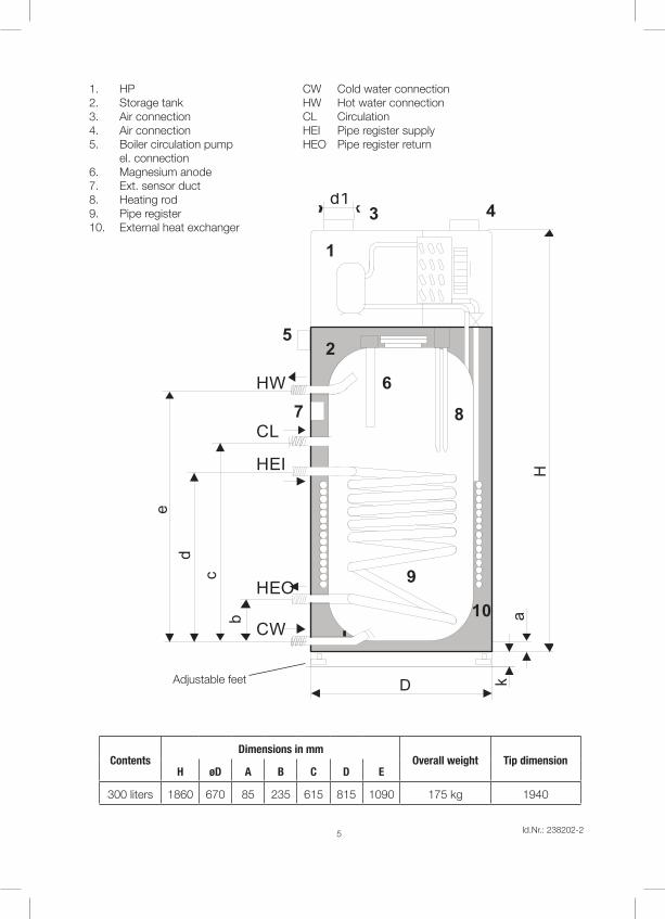
1. HP CW Cold water connection2. Storage tank HW Hot water connection3. Air connection CL Circulation4. Air connection HEI Pipe register supply5. Boiler circulation pump HEO Pipe register return el. connection6. Magnesium anode7. Ext. sensor duct8. Heating rod9. Pipe register10. External heat exchanger
ContentsDimensions in mm
Overall weight Tip dimensionH øD A B C D E
300 liters 1860 670 85 235 615 815 1090 175 kg 1940
a
k
b
c
d
e
H
D
d1
1
2
6
8
9
5
10
3 4
7HW
CL
CW
HEI
HEO
Adjustable feet

Id.Nr.: 238202-2 6
5.1 Refrigerant circuit (functional principle of the HP)
The refrigerant circuit is a closed system, wherein the refrigerant R134a circulates as the energy car-rier. In the lamellar heat exchanger, the heat is extracted from the sucked in air at a low evaporation temperature and transferred to the refrigerant. The vaporous refrigerant is sucked into a compressor, compressed to a higher pressure and temperature level, and transported to the condenser, where the heat taken up in the evaporator and part of the absorbed compressor energy are passed on to the water. Subsequently, the high condensation pressure is relieved using a throttle element (expansion valve) down to the evaporation pressure, and in the evaporator, the refrigerant can take up heat from the sucked in air again.
5.2 Water heater
The water heater is double-vacuum-enameled on the inside, polyurethane-foamed on the outside, and encased with steel sheet. For bivalent heat-pump operation, a heat exchanger is installed in series in connection with the boiler. Additionally, an installed protective anode prevents corrosion damage in case of a possible damage to the enamel coating on the inside of the boiler.
5.3 Additional electric heating rod
The installed electric heating rod EH with outputs of 1.5 kW or 2.0 kW serves for:• Fast water heating – For that, heat pump and heating rod work simultaneously.• Protective function of the evaporator – In case of the temperature being too low, the electric heating
rod is automatically switched on, if the heat pump is set to summer operation.• Alternative heating – For example, in case of an operating failure of the aggregate.
5.4 Safety elements of the heat pump
Frost protection sensorThe heat pump has an air temperature sensor installed, which measures the air flowing through the evaporator, and at 7 °C switches off the heat pump for 30 minutes.For heat pumps with an electric heating rod, this is switched on in summer operation, as soon as the air temperature drops to below 7 °C. In winter operation, at this air temperature, the circulation pump of the connected boiler is switched on.
Operating and safety thermostat of the electric heating rodThe electric heating rod has an operating and safety thermostat installed, which is set to a temperature of 65 °C.Attention! With the electric heating rod in operation, the water is always heated to approx. 65 °C, since only the upper area of the hot water tank is heated. In this case, the controller does not indicate the actual water temperature, because its sensor is inserted in the lower area of the hot water tank, and in this case measures a lower water temperature. The safety thermostat switches off at 75 °C and must be reset manually.
Control of the hot water temperature in the hot water tankThe OPTITRONIC controller serves controlling and heating the water to the desired temperature.Depending on the desired water temperature, the controller switches the compressor and ventilator off or on. In certain cases, the controller also switches the electric heating rod or the circulation pump of the heating boiler on or off. The maximum water temperature to be set is 55 °C; upon actuating the shortcut button HT, the water temperature is 60 °C.

Id.Nr.: 238202-27
High-pressure pressure control (HD)The high-pressure pressure control protects the heat pump against inadmissibly high operating pres-sures in the refrigerant circuit. In case of an incident, the pressure control switches off the heat pump. The heat pump is automatically restarted following pressure reduction in the refrigerant circuit. For that, the following is displayed: >E7<.
5.5 Operating conditions
The ambient temperature for normal use is to be between +7 °C and +35 °C. The air must be clean and the relative air-humidity should not exceed 50 % at +40 °C air temperature. In case of lower ambient temperatures, a higher relative air-humidity is permitted, too.Assembly must not take place at an altitude of more than 2000 m. For systems used at an altitude of more than 1000 m, heating as well as air cooling performance are reduced due to the air pressure.Under no circumstances may the heat pump be installed in places in which the air could contain pollu-tants or toxins (stables, storage rooms for hazardous materials, in the open air etc.).
5.6 Storage tank connection
The connection to the water line must be executed according to the regulations applicable to the con-nection of water heaters. The following figure shows how the water line is connected. The maximum pressure in the water line must not exceed 6.0 bars.
1. Pressure reduction valve2. Return valve3. Shut-off valve4. Safety valve5. Expansion tank6. Drain valve Connection of the HP to the water line
Adjustable feet

Id.Nr.: 238202-2 8
The bare-tube heat exchanger has to be professionally flushed prior to execution of the initial installa-tion (we furthermore recommend the installation of a dirt filter). If the bare-tube heat exchanger is not used upon operation of the storage tank (e.g. heat pump only), then it has to be completely filled with a respective glycol mixture in order to avoid corrosion caused by the resulting condensation water. In that, following filling, the filled bare-tube heat exchanger must not be closed at both ends (pressure expansion with temperature).
5.7 Filling the system with water
Following connection of the heat pump to the water line, the system has to be completely filled with water. Only when the water exits at the extraction point without forming bubbles, the system has been filled and completely vented.
The heat pump must never be commissioned without water in the boiler – there is the risk of damage to the compressor!
5.8 Condensate drainage
Due to moisture in the air, condensation water is formed in the heat pump. Depending on season and hot water demand, this is about 1 to 5 liters per day. This condensation water may, e.g., be used for a steam iron or for watering plants.In order to drain the condensation water, a discharge hose is attached to the device, which is located at the right-hand rear of the device. Attention: There is a check valve installed in the end of the hosepipe, which may only be remo-ved if a siphon is fitted.If in the installation room, free discharge of the condensation water is not possible, a collection tank with a capacity of at least 10 liters must be provided for this reason.Attention: In case longer air ducts are used, it is absolutely indispensable to install a non-return valve at the lower end of the condensate pipe for correct condensate drainage and non-transmission of the tap odor.
5.9 Electrical installation
Once the heat pump has been connected to the water line and properly filled and vented, electrical connection may be undertaken.
The connecting cable must only be plugged into an earth contact-type socket (16 A, 230 V / 50 Hz).
Circulation pump
Heating rod
Compressor
Ventilator
230 V AC 50 Hz
1. Drainage hose; 2. Collection container or drain pipe; 3. Ceck valve

Id.Nr.: 238202-29
5.10 Circuit diagrams
Electrical circuit diagram
Terminals for the circulation pump (boiler) in the terminal box (max. 300 W).
LN
S1: Pressure control
Circulation pump
Heating rod
Compressor
Ventilator
L - brown
N - blue
Earthing
230 V AC 50 Hz
T1: Hot water temperature sensor
T1: Ambient air temperature sensor
Circulation pump of auxiliary heating (boiler)

Id.Nr.: 238202-2 10
5.11 Commissioning of the heat pump
• Modern and visually simple representation of the information about the operating condition via display and control lamp
• Shortcut buttons for water temperature setting (+, -)• Shortcut button for switchover of the operating mode (P)• Shortcut button HT for one-time water heating to 60 °C (anti-Legionella protection)• Possibility for fast water heating (heat pump and additional heat source)• Automatic switchover to the spare heat source upon cooling of the ambient temperature (boiler
or electric heating element)• Anti-Legionella program with automatic water heating to 60 °C at intervals of 14 days• Self-diagnosis• Identification and display of operating errors
5.11.1 Operating procedure of the heat pump
With the heat pump properly connected to the power and water supply, the controller version of the set operating program or >P1<, respectively, is displayed on the screen after 2 seconds, as well as all pa-rameters and their values. 30 seconds following electrical connection, the system starts up and starts heating the water. The heat pump is switched on. Once the pre-set switch-off temperature of 52 °C has been reached, the heat pump switches off automatically. As soon as the water has cooled by 5 °C, i.e. to 47 °C, the heat pump is switched on again. The switch-off temperature may be chosen by the user, however, is limited to a maximum of 55 °C (temperature controller blockage). Water heating to 60 °C is restricted to this value and is not adjustable. The ambient air temperature, at which switch-over to the spare heat source takes place, has already been set to 7 °C. This temperature can be randomly set by the user (instructions in the following).
5.11.2 Brief operating instructions
The display on the operating panel in the basic menu shows the current water temperature in the storage tank.
Water temperature displayDisplay of the selected mode of ope-ration/program
Switch-over to summer/win-ter mode of operation
Shortcut button for one-time water heating to 60 °C(anti-Legionella protection)
Setting of the water tempe-rature andparameter display

Id.Nr.: 238202-211
Functional description – Flashing display:
Flashing display Selected program
Description
☼ not illuminatedP0
The heat pump is switched off and only the water temperature display in the storage tank is active. not illuminated
☼ illuminated
P1
The heat pump is heating the water to the set temperature with the compressor only. The heat pump heats up the water. With the air temperature being too low, the compressor is swit-ched off for reasons of safety. Attention: In case of a defective air sensor, this error is indicated, but the water is still heated further.
not illuminated
☼ not illuminatedP2
The hot water temperature set is only heated with the heating boiler. Comment: The air temperature has no influence on the function. illuminated
☼ not illuminatedP3
(WPK 301 LF)
The hot water temperature set is heated using an electric heating rod. Comment: The air temperature has no influence on the function. flashing
☼ illuminatedP4
The heat pump is heating the water to the set temperature with the compressor (automatic mode of operation). The heat pump is heating the water depending on the air temperature. If the switchover temperature is undercut, the heat pump automati-cally switches over to heating with the heating boiler.
illuminated
☼ illuminatedP5
(WPK 301 LF)
The heat pump is heating the water to the set temperature with the compressor (automatic mode of operation). The heat pump is heating the water depending on the air temperature. If the switchover temperature is undercut, the heat pump automati-cally switches over to heating with the electric heating rod.
flashing
Particularities In case of switchover to the spare heat source (P4 and P5 only).
☼ flashing
P4, P5
If the air temperature is too low or if the switchover temperature was undercut, for program P4, the water is heated with the heating boiler, for program P5, with the electric heating rod. For that, the compressor is switched off for reasons of safety.
flashing or illuminated
Comment: Upon actuating the >P< button, the selected program is displayed (the selected program can also be controlled via the flashing display – see table above).With each further pressing of the >P< button, various available programs can be selected within 8 seconds.Attention: With each selected program, the heat generator is selected, too, which takes over water heating.

Id.Nr.: 238202-2 12
1. Setting of the hot water temperature: Upon pressing the >+< or >-< buttons, the currently set water temperature is displayed. With each subsequent actuation (within 8 seconds), this, however, may be changed. 5 seconds after the flashing has stopped, the new setting is saved.
2. Switchover between various modes of operation: Switchover between the modes of operation is perfor-med using the >P< button. The selected mode of operation is displayed with illumination of the mode of operation indicator and the inscription with the first pressing of the >P< button (see table above). With each subsequent actuation of the >P< button within 8 seconds, the available modes of operation may be changed. Recommendation: If the ambient temperature is above 7 °C, it is reasonable to heat the water with the heat pump only (P1, P4, P5).
3. One-time thermal disinfection: The one-time water heating to 60 °C is switched on with the HT button. The indicator on the button illuminates until the end of the water being heated. Pressing the HT button again, the heating process can be stopped early. We recommend an interval of 14 days, which should not be undercut, since the energy consumption is higher by approx. 1/3 than with normal operation of the heat pump. Water heating is performed using the heat source, which was set and selected with the mode of operation (e.g. P1 – compressor, P2 – boiler). Should the heating not take place within 12 hours, the function is switched off and over to normal water heating.
4. Faster water heating: With programs P4 or P5, the function of fast (simultaneous) water heating is available, for which both heat sources are operated (heat pump and electric heating element in pro-gram P5, heat pump and boiler in program P4). This function is switched on with the HT button by kee-ping it pressed for 20 seconds. The indicator of the HT button flashes until the set water temperature has been reached. The function can be stopped early by pressing the HT button again.
5.11.3 Operating programs
1. Water heating with the compressor only (P1): The water is heated until either the set temperature is reached or the ambient temperature drops below the set value. If the hot water is cooling down by 5 °C, the compressor starts the heating process again. If the ambient temperature is cooling to below the set value, the compressor is switched off for 30 minutes or until a higher ambient temperature is reached, respectively, for safety reasons.
2. Water heating with the boiler only (P2): The water is heated by the circulation pump of the boiler until the set temperature is reached. If the water is cooling down by 5 °C, the circulation pump is switched on again automatically.
3. Water heating with the electric heating element only (P3): The operating and safety thermostat of the electric heating element is set to 65 °C, switches off upon reaching the water temperature of the hea-ting element, and independently switches on again when the water temperature is dropping. Since the sensor is located underneath the electric heating element, the temperature displayed for a heating element installed at the top may deviate from the set temperature.
4. Water heating with the compressor and automatic switchover to the spare heat source upon undercutting of the air temperature (P4 and P5): The heat pump automatically works in compressor operation until the set water temperature has been reached or the ambient temperature has been undercut, respectively. If the ambient temperature drops below the set value, the controller automatically switches over to heating with the spare heat source (P4 – heating with boiler, P5 – heating with electric heating element). During heating with the spare heat source, the indicator ☼ is flashing. After 30 minutes, at the latest, or when the ambient temperature is increasing again, the controller switches back to heating using the compressor.
Id.Nr.: 238202-213
5.11.4 Parameter display
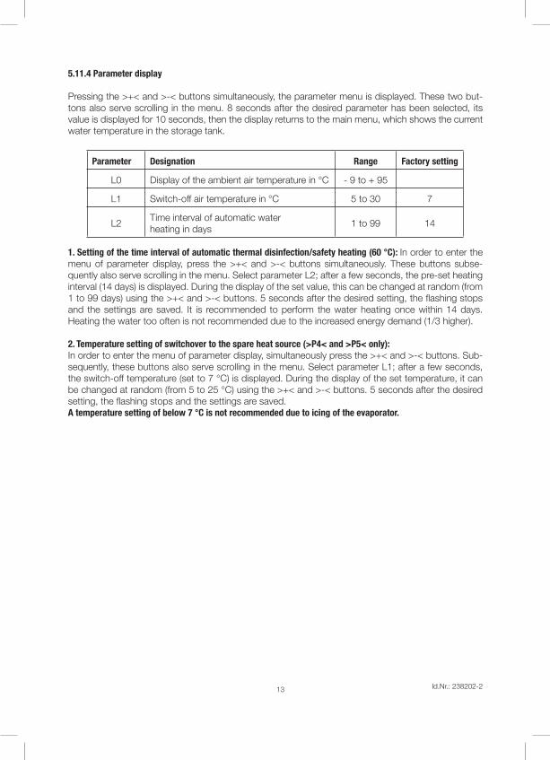
Pressing the >+< and >-< buttons simultaneously, the parameter menu is displayed. These two but-tons also serve scrolling in the menu. 8 seconds after the desired parameter has been selected, its value is displayed for 10 seconds, then the display returns to the main menu, which shows the current water temperature in the storage tank.
Parameter Designation Range Factory setting
L0 Display of the ambient air temperature in °C - 9 to + 95
L1 Switch-off air temperature in °C 5 to 30 7
L2Time interval of automatic water heating in days
1 to 99 14
1. Setting of the time interval of automatic thermal disinfection/safety heating (60 °C): In order to enter the menu of parameter display, press the >+< and >-< buttons simultaneously. These buttons subse-quently also serve scrolling in the menu. Select parameter L2; after a few seconds, the pre-set heating interval (14 days) is displayed. During the display of the set value, this can be changed at random (from 1 to 99 days) using the >+< and >-< buttons. 5 seconds after the desired setting, the flashing stops and the settings are saved. It is recommended to perform the water heating once within 14 days. Heating the water too often is not recommended due to the increased energy demand (1/3 higher).
2. Temperature setting of switchover to the spare heat source (>P4< and >P5< only):In order to enter the menu of parameter display, simultaneously press the >+< and >-< buttons. Sub-sequently, these buttons also serve scrolling in the menu. Select parameter L1; after a few seconds, the switch-off temperature (set to 7 °C) is displayed. During the display of the set temperature, it can be changed at random (from 5 to 25 °C) using the >+< and >-< buttons. 5 seconds after the desired setting, the flashing stops and the settings are saved.A temperature setting of below 7 °C is not recommended due to icing of the evaporator.

Id.Nr.: 238202-2 14
6. Installation site of the heat pump
The heat pump may be installed in any room, except for the living space. The room may have any size, but it must at least be large enough for the installation of the heat pump (approx. 20 m³). The minimum room height must be 2200 mm.
Under no circumstances may the heat pump be installed in places in which the air could contain pollu-tants or toxins (stables, storage rooms for hazardous materials, in the open air etc.).
The heat pump is designed such that it sucks in the air for ventilation via the duct pipe system from the room or from the environment. The air sucked in passes on its heat to the heat pump and is then, depending on requirements, wishes and demand, returned to the selected room or the environment.The heat pump enables the following types of ventilation, which depend on the design of the duct pipe system:
Suction from the room – blowing out into the same or a remote room
Suction from the adjoining room – blowing out into the same adjoining room (cooling of the adjoining room)
Id.Nr.: 238202-215
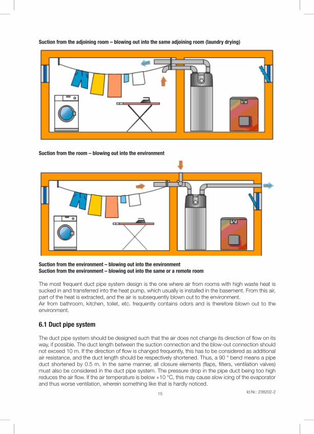
Suction from the adjoining room – blowing out into the same adjoining room (laundry drying)
Suction from the room – blowing out into the environment
Suction from the environment – blowing out into the environmentSuction from the environment – blowing out into the same or a remote room
The most frequent duct pipe system design is the one where air from rooms with high waste heat is sucked in and transferred into the heat pump, which usually is installed in the basement. From this air, part of the heat is extracted, and the air is subsequently blown out to the environment.Air from bathroom, kitchen, toilet, etc. frequently contains odors and is therefore blown out to the environment.
6.1 Duct pipe system
The duct pipe system should be designed such that the air does not change its direction of flow on its way, if possible. The duct length between the suction connection and the blow-out connection should not exceed 10 m. If the direction of flow is changed frequently, this has to be considered as additional air resistance, and the duct length should be respectively shortened. Thus, a 90 ° bend means a pipe duct shortened by 0.5 m. In the same manner, all closure elements (flaps, filters, ventilation valves) must also be considered in the duct pipe system. The pressure drop in the pipe duct being too high reduces the air flow. If the air temperature is below +10 °C, this may cause slow icing of the evaporator and thus worse ventilation, wherein something like that is hardly noticed.

Id.Nr.: 238202-2 16
It is necessary to install at least one 90 ° pipe bend in order to avoid air mixture between the air ducts respectively sucking in and blowing out.
6.2 Connection of the duct pipe system
The figure shows the cover of the heat pump. The cover has two supports, which are 40 mm high and have an outer diameter of Ø 150 or Ø 160 mm. The access to the interior parts of the heat pump is covered with a safety guard, which must not be removed.
Deckel der WPA 302 E-LF mit ø 150 mm Rohrstutzen
Max. 10 mMin. 0,6 m Min. 1,2 mMin. 0,6 m Min. 1,2 m
Min. 0,8 m
Blowing outSuction
Id.Nr.: 238202-217
6.3 Advantages of the heat pump with air duct
The heat pump with air duct has a number of advantages over the standard compact version and also over the design with a separate evaporator.• The heat pump may be installed in any room, which is sufficiently large for it.• The heat pump enables ventilation of a selected room.• The heat pump enables discharge of the room air as well as supply of fresh air from the environ-
ment.
When selecting the room, consider the diameter and the height of the heat pump. Above the device, there must be sufficient space for the pipe duct connections. The minimum distance to the walls is 0.5 m.
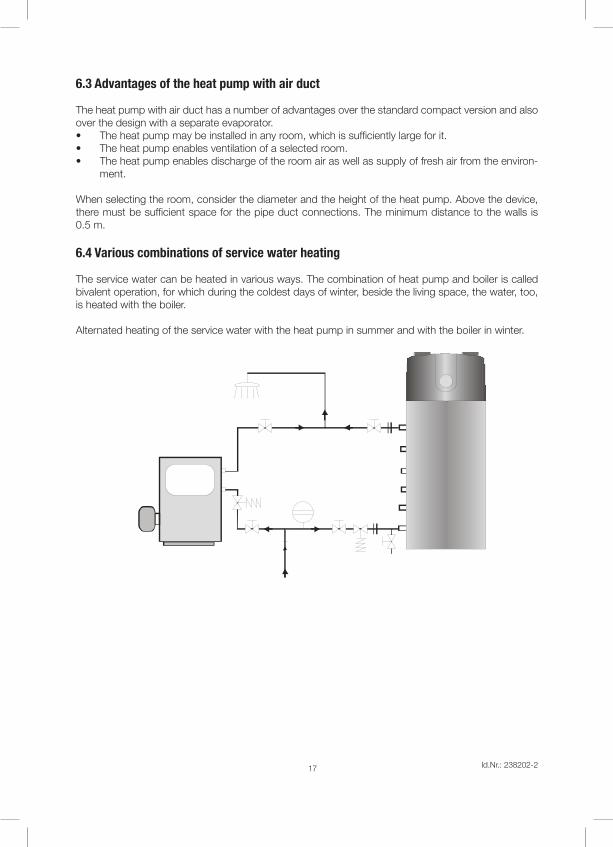
6.4 Various combinations of service water heating
The service water can be heated in various ways. The combination of heat pump and boiler is called bivalent operation, for which during the coldest days of winter, beside the living space, the water, too, is heated with the boiler.
Alternated heating of the service water with the heat pump in summer and with the boiler in winter.

Id.Nr.: 238202-2 18
Post-heating of the service water with the boiler in the HP boiler
Post-heating of the service water with the solar plant

Id.Nr.: 238202-219
7. Notes on safety
The device must only be operated by the specialist company and respectively instructed per-sons, who via these operating instructions guarantee safe operation and maintenance.
It is prohibited to move or relocate the device as well as to clean or repair it during operation.
Prior to installation and any later access to the interior of the device, make yourself familiar with the contents of the operating instructions for safe operation and maintenance in any case.
The electrical installation of the device must be performed by an authorized person (certified electrician) with the device in a completely discharged state.
It is prohibited to relocate the heat pump and to lean any objects against the heat pump.
Around the heat pump, there must be sufficient space for fast and easy access for repair and maintenance.
If during heat pump operation the water temperature in the boiler rises to above 75 °C, the cus-tomer service must be informed in any case.
Disconnect the device from the power supply prior to any work at the heat pump.
The heat pump must be installed such that the power plug is freely accessible at any time. The device must be erected on a stable, level and non-slippery floor. An area of at least 2 m² must be ensured for operation. During installation, operation and maintenance, sufficient illumination of the heat pump should be given, which should be at least 150 luces. It must be ensured that the device poses no risk for anybody, and that children as well as unauthorized persons cannot gain access during operation.
8. Instructions for secure up-keep
Upon compliance with these instructions for use for safe operation and up-keep, the heat pump will work without additional servicing and maintenance.
Recommended inspections:• An inspection of the magnesium anode for protection of the water heater should be undertaken
every two years.• Inspection of the safety valve at the cold water connection – unscrew the valve a little until the
water is flowing.• Inspection of the evaporator lamellas – the lamellas must not be covered in dust, since this gra-
dually reduces the performance of the heat pump. Should the lamellas be covered in dust, switch off the heat pump, unscrew the screws, remove the upper plastic cover, and clean the lamellas with a vacuum cleaner or blow air through the lamellas. In that, observe that the lamellas or other parts of the heat pump are not damaged.
Following commissioning, the heat pump should not be decommissioned for longer than 1 month, as this can result in the failure of the lubrication for the compressor piston, which can render the heat pump inoperable. If this results in damage then the manufacturer shall exclude any claims against the guarantee.

Id.Nr.: 238202-2 20
Inspections prior to a damage report to the customer service:• Check, whether everything is fine with the electrical connection lines.• Check, whether the air outlet from the evaporator is obstructed by the grids.• Measure the temperature in the room where the heat pump is installed and check, whether it lies
within the range of specified temperatures.
The device must be connected in compliance with the national regulations.
9. Transport and storage
During transport, the heat pump is protected with a protective film and cardboard packaging in order to prevent damages like impressions and scratches. Following transport, the device must stand upright for at least 2 hours, so that the distributed refrigerant flows back to the compressor.
The device must only be relocated or moved when it is not in operation.
The admissible temperature during transport and storage lies between 10 and 45 °C, wherein in the short term up to 24 hours, up to 55 °C are admissible, too.
The heat pump must not be positioned horizontally under any circumstances.
10. Disassembly and decommissioning
The device as a whole, according to its technical concept design, has a lifetime of several years. In-dividual components, however, may also be exchanged in case of possible interferences, wear and mechanical damage. In case of repair, only original spare-parts must be used.
Following decommissioning, the device must be disposed of at a landfill for industrial waste according to its waste classification. Components hazardous to the environment must be disposed of at a res-pectively specified collection point.
11. Notes on safety
The device was produced based on technical standards, which enable the manufacturer to attach the CE marking on the device. As a warning against possible risks upon operating the heat pump, the device has been equipped with respective signs and symbols (pictograms).
The meaning of the signs and symbols (pictograms) can be retrieved from the following figures.

Id.Nr.: 238202-221
Carefully read the operating instructions
Risk of an electric shock
The device must not be positioned hori-zontally. Transport
and use in an upright position.
Besides symbols (pictograms) and signs, a further label or sticker is attached to the device, containing the technical data of the device.
12. Elimination of technical defects
Warning display
A1Switch-off of the HP due to the ambient temperature being too low
Aerate the room so that it warms up to the correct temperature
Set the switch-over temperature of the spare heat source to a lower value
In case of connection to a boiler, switch over operation to P2 or P3. Heating takes place automatically by the boiler or heating rod.
A3
Switch-off of the HP, because the ambient temperature exceeding the highest limit value of 37 °C
Aerate the room so that the temperature drops below this value
If the temperature in this room is constantly above this value, another installation site should be chosen
Error indication Cause Solution
E7Pressure in the system too high
Check, whether there is enough water in the storage tank
Using the >+< button, the error is deleted. If the error occurs again, call customer services
Alternating E8
and --Water temperature sensor not connected
Check, whether the sensor is connected or call customer services, respectively
Alternating E8
and --
Water temperature sensor damaged
First reset the HP. Check sensor connection or sensor cable, respectively. If the error occurs again, call customer services.

Id.Nr.: 238202-2 22
Alternating E9
and --Air temperature sensor not connected correctly
Check, whether the sensor is connected or call customer services, respectively
Alternating E9
and --
Air temperature sensor damaged
First reset the HP. Check sensor connection or sensor cable, respectively. If the error occurs again, call customer services
Description of the problem
Cause Solution
Water is not heated up to the set tem-
perature
Boiler heating circuit for service water heating not closed
Close the valve for the boiler heating circuit
Circulation looses too much heat
Switch off the pump and close the valve of circulation
HP constantly running / not swit-
ching off
There is a gas leak some-where in the system
Call customer services
Evaporator damage due to careless cleaning
Call customer services
Too little gas in the system Call customer services
Circulation looses too much heat
Switch off the pump, close the valve for the circulation
Uncontrolled heat loss from the boiler (hot water consumption too high)
Check any possible discharges from the boiler
HP causes a lot of noise
The ventilator touches the housing or the safety guard
Call customer servicesCompressor damage (fixing spring damage)
The condenser touches the boiler exchanger
Heating rod not effective
Controller shows tempe-rature below the heating rod, therefore the display temperature is lower
Check, whether the tapping water is warm
Temperature in the storage tank exceeding 75 °C, safe-ty thermostat switched off
Reset safety thermostat
Evaporator freezing
Air flow too small Air inlet and outlet must be free
Ventilator damage Call customer services
Temperature in the room of air recording too low
Set the switchover temperature to the higher value

Id.Nr.: 238202-223
Warranty, Guarantee and Product LiabilityThe warranty is granted in accordance with the statutory provisions of the Republic of Austria, as well as of the EU.
1. Prerequisite for the provision of warranty services by Austria Email AG (hereinafter referred to as AE AG) shall be the presentation of the paid invoice for the purchase of the device for which the warranty service is claimed, whereby the identity of the device with regard to the model and the manufacturing number must be evident from the invoice and must be documented by the claimant. The General Terms and Conditions, Terms and Conditions of Sale and Delivery of AE AG shall apply exclusively.
2. To the extent required by the law, respectively in the Operator’s Manual and Installation Instructions, the assembly, erection, connection and commissioning of the unit for which the claim is presented must have been carried out by a licensed electrician or installation firm, duly observing all applicable rules. The tank (without outer shell and plastic outer shell) must be protected from sunshine to avoid discolouring of the PU foam and potential warping of plastic components.
3. The room in which the device is operated must be free of frost. The unit must be mounted in a location that may reasonably be expected, i.e. it must be possi-ble to access and replace the unit without difficulty for the purpose of necessary maintenance, repairs and possible replacement. The costs for any necessary changes to the structural conditions (e.g. doors and passages too narrow) are not governed by the guarantee and warranty declaration and therefore shall be rejected on the part of AE AG. If the water boiler is set up and operated in uncommon locations (e.g. attics, living rooms with water-sensitive floors, store rooms, etc.), the possibility of water leakage must be taken into account and provisions made for collecting and discharging the water leakage in order to prevent secondary damage within the meaning of product liability.
4. The following is not covered by the warranty and guarantee: inappropriate transport, normal wear and tear, intentional or negligent damage, use of force of any kind or description, mechanical damage or damage
caused by frost or also by exceeding the operating pressure stated on the rating plate, even if only once, use of connection fittings that do not comply with the standard, use of defective tank connection fittings and unsuitable and defective service fittings. Breaking of glass and plastic components, possible colour differences, damage due to improper use, in particular non-observance of the mounting and operating instructions (Operating and Mounting Instructions), damage by external influence, connecting to incorrect voltage, corrosion damage as a consequence of aggressive waters (water not suitable for drinking) in accordance with the national regulations (e.g. Austrian ordinance on drinking water, TWV – Fed. Law Gazette II No. 304/2001), deviations between the actual drinking water temperature at the tank fitting and the specified hot water temperature of up to 10°K (hysteresis of the controller and possible cooling due to pipelines), Insufficient water conductivity (min. 150 µs/cm), operational wear of the magnesium anode (wearing part), natural formation of boiler scale, lack of water, fire, flood, lightning, overvoltage, power failure or other types of force majeure. Use of non-original and company-external components such as e.g. heating elements, reactive anode, thermostat, thermometer, ribbed tube heat exchanger, etc., ingress of foreign particles or electrochemical influences (e.g. mixed installations), failure to observe the design documents, unpunctual and undocumented renewal of the installed protective anode, no or improper cleaning and operation, as well as any deviations from the standard that reduce the value or functionality of the device only slightly. Fundamental compliance with all regulations in ÖNORM B 2531, DIN 1988 (EN 806), DIN 1717, VDI 2035 or the corresponding national regulations and laws must be ensured.
5. In the case of an authorised complaint, this must be reported to the next available customer service location of AE AG. The same reserves the right to decide whether a defect component shall be replaced or repaired or whether a defect device shall be replaced by an equivalent fault-free device. Furthermore, AE AG explicitly reserves the right to request that the rejected device be returned by the buyer.
6. Repairs under warranty must be performed exclusively by persons authorised to do so by AE AG. Replaced parts shall remain the property of AE AG. If a repair of the hot water heater should be required in connection with necessary service work, the Manufacturer shall invoice these as repair and prorated material costs.
7. Any intervention by third parties without our express instruction, even if performed by a licensed electrician, shall have the effect of voiding the warranty. Costs for repairs carried out by third parties shall be replaced only if AE AG has previously been requested to remove the defect and if AE AG shall have failed to satisfy its obligation to replace the defective item or repair the defect or if it shall have failed to do so within a reasonable period of time.
8. Neither the performance of works under warranty or guarantee, nor the performance of service and maintenance works shall renew or extend the term of warranty.
9. Transport damage shall be investigated and possibly accepted only if it is reported to AE AG in writing on the next following workday after delivery at the latest.10. Claims over and above the warranty, if legally permissible, in particular claims with respect to compensation of damages and consequential damages, shall be
excluded. Prorated labour time for repairs as well as the costs of restoring the original condition of the unit must be paid in full by the buyer. In accordance with this warranty declaration, the warranty shall apply only to repair or replacement of the unit. The provisions of the Terms and Conditions of Sale and Delivery of AE AG shall, unless amended by these Terms and Conditions of Warranty, remain fully in place.
11. Services that are not performed within the scope of these Terms and Conditions of Warranty shall be charged.12. No claims under warranty shall be considered by AE AG unless full payment for the device has been made to AE AG and unless the claimant has fully satisfied
all obligations arising to him vis-à-vis the seller.13. The enamelled internal boiler for water heaters is warranted for the specified period from the delivery date provided all warranty terms described under Points
1 to 12 are observed with in full. If the warranty terms have not been met, the legal warranty requirements of the respective country from which the appliance was shipped shall prevail.
14.With regard to the assertion of claims pursuant to the Austrian Product Liability Act it must be noted: Potential claims under the title of product liability relating to the regulation of damages due to a defective product (e.g. a human’s body is injured, his health is
damaged or any corporeal property differing from the product is damaged) shall only be justified if all the prescribed measures and requirements for flawless and normal operation of the unit have been fulfilled.
These include e.g. the mandatory and documented anode replacement, the connection to the correct operating voltage, any damage due to improper use must be avoided, etc. These standards are based on the assumption that if all the regulations (standards, assembly and operating instructions, general gui-delines, etc.) are observed, the defect in the unit or product causal for occurrence of the secondary damage would not have occurred. It is further imperative that all the documentation necessary for handling of a claim, such as e.g. the type and fabrication number of the unit, the vendor’s invoice and the invoice of the licensed electrician or installation firm, as well as a description of the malfunction be provided, as well as the defective unit itself for examination in the lab (absolutely necessary, as the unit will be investigated by an expert and the cause of the defect analysed). In order to exclude any possibility of mistaken identity of the unit during transportation, the unit must be labelled with a clearly legible label (ideally with the end customer’s address and signature). Appro-priate photographic documentation of the extent of damage, the installation (cold water inflow, hot water outflow, heating inflow and outflow, safety fittings, expansion vessel if applicable), as well as the defective part of the tank is required. AE AG further expressly reserves the right to demand the submission of documentation and units or unit components by the buyer for the purpose of clarification.
The damaged party’s full burden of proof that the damage was caused by the product of AE AG is prerequisite for the payment of any benefits under the title of product liability. Claims for damages pursuant to the Austrian Product Liability Act are moreover justified only for any amount exceeding the amount of 500 euros (deductible amount). Until all the facts and circumstances as well as the problem causally underlying the defect have been ascertained, any possible fault on the part of AE AG shall be ruled out explicitly. Any non-observance of the operating and assembly instructions as well as the relevant standards shall be deemed negligence and shall result in an exclusion of any liability for damages.
The figures and data are not binding and may be amended without notice in the interest of technical improvement.Misprints and technical changes reserved.

Headquarters and plant:Austria Email AG
A-8720 Knittelfeld, Austriastraße 6Tel.: (03512) 700-0, Fax: (03512) 700-239
Internet: www.austria-email.atE-Mail: [email protected]
Vienna, Lower Austria, BurgenlandA-1230 Wien, Zetschegasse 17
Tel.: (01) 615 07 27Fax: (01) 615 07 27-260
E-Mail: [email protected]
Styria, Carinthia, East TyrolA-8053 Graz, Am Wagrain 62
Tel.: (0316) 271 869Fax: (0316) 273 126
E-Mail: [email protected]
Upper Austria, SalzburgA-4600 Wels, Gärtnerstraße 17
Tel.: (07242) 45 071Fax: (07242) 43 650
E-Mail: [email protected]
Tyrol, VorarlbergA-6020 Innsbruck, Etrichgasse 24
Tel.: (0512) 347 951Fax: (0512) 393 353
E-Mail: [email protected]
Addresses of the sales branches: