workshop manual - sdp.vdlbuscoach.com
TRANSCRIPT

Citea LLE E6 EBS1-CWORKSHOP MANUAL
1640 DD0857_02
Main group 7

Citea LLE E6 EBS1-C
ForewordThis workshop manual contains all the relevant information to help when tracing and solving technical problems, when making adjustments and when carrying out repair work. The book contains diagrams, system descriptions, fault finding instructions and work instructions. It also contains safety regulations, which must be strictly observed.
Experienced mechanicsThe technical information and the explanations of the repair work stated in this workshop manual have been compiled with the utmost care.
Whilst compiling this workshop manual, it has been assumed that the mechanic has the necessary experience and has had the required education or training to be able to carry out the work in a responsible and safe manner.
Vehicle typeThe information in this manual has been updated until the time of printing and only concerns the following vehicle series:- Citea LLE 120-250 ISB6.7 E6
In this manual, this series of vehicles is referred to as: "Citea LLE E6 EBS1-C".
ISB6.7 indicates that the contents of this manual relate to the 6.7 litre ISB6.7 engine from Cummins.
E6 indicates that this manual contains guidelines for the engines which meet the Euro 6 emission requirements.
“EBS1-C” indicates that this vehicle series has a 1st gen-eration EBS brake system.
DD0857_02

Citea LLE E6 EBS1-CCONTENTS
0
1
2
3
4
5
6
7
8
9
7
Technical information
Steering mechanism: general information . 1-1Battery terminal clamp tightening torques....... 1-1
Steering box and steering mechanism ....... 2-1Steering box.................................................... 2-1Tightening torques .......................................... 2-3
Tandem pump ............................................... 3-1General information ........................................ 3-1Tightening torques .......................................... 3-2
Lines/reservoir .............................................. 4-1General information ........................................ 4-1Tightening torques .......................................... 4-3
Steering column............................................ 5-1General information ........................................ 5-1Steering angle sensor ..................................... 5-2Tightening torques .......................................... 5-3
Front axle....................................................... 6-1General information ........................................ 6-1Tightening torques .......................................... 6-4
Special tools.................................................. 7-1Tools available from VDL Bus & Coach.......... 7-1Tools not available from VDL Bus & Coach.... 7-4
Diagnosis
Steering mechanism: general information . 1-1Fault finding tables.......................................... 1-1Tyre wear diagnosis........................................ 1-8
Steering mechanism: general in-formation
Safety regulations......................................... 1-1Safety regulations ........................................... 1-1
General information...................................... 2-1General view of the hydraulic section ............. 2-1Description of the hydraulic section ................ 2-2
Inspection and adjustment .......................... 3-1Steering system: inspecting using a pressure gauge .............................................................. 3-1Steering mechanism: inspecting using a test box .. 3-4Steering box: checking the attachment......... 3-11Hydraulic middle position: checking.............. 3-12Steering shaft universal joints: checking the attachment .................................................... 3-13
Draining and filling ....................................... 4-1Steering mechanism: draining and filling ........ 4-1
Steering box
Safety regulations .........................................1-1Safety regulations............................................1-1
General information ......................................2-1General view of the steering box .....................2-1Description of the operation.............................2-2
Inspection and adjustment ...........................3-1Poppet valves: inspecting and adjusting .........3-1Pressure point: inspecting and adjusting.........3-9Sector shaft oil seal: checking for leaks ........3-11Steering box: checking the internal resistance..3-12Pitman arm: checking the component number .3-13
Removal and installation ..............................4-1Steering box: removing and installing the complete steering box .....................................4-1Pitman arm: removing and installing ...............4-4Ingoing shaft oil seal: removing and installing .4-7Sector shaft oil seal in the side cover: removing and installing....................................................4-9Sector shaft oil seal on the same side as the pitman arm: removing and installing..............4-11Pressure limiting valve: removing and installing4-14
Steering pump
General information ......................................1-1Operation of the steering pump .......................1-1
Inspection and adjustment ...........................2-1Flow regulating valve: inspecting.....................2-1
Removal and installation ..............................3-1General information .........................................3-1Steering pump: removing and installing ..........3-2
Lines and reservoir
General information ......................................1-1Lines ................................................................1-1Reservoir .........................................................1-2
Inspection and adjustment ...........................2-1Steering mechanism: checking the fluid level..2-1Steering mechanism lines/hoses and connections: checking .....................................2-3
Removal and installation ..............................3-1Steering mechanism filter: removing and installing...........................................................3-1Reservoir: removing and installing ..................3-2Lines: removing and installing .........................3-3
DD0857_02

0
1
2
3
4
5
6
7
8
9
7CONTENTSCitea LLE E6 EBS1-C
Bevel box
General information...................................... 1-1General view of the bevel box......................... 1-1Operation ........................................................ 1-1
Removal and installation.............................. 2-1Bevel box: removing and installing ................. 2-1
Steering column
General information...................................... 1-1General view of the steering column............... 1-1System description of the steering column ..... 1-2Steering angle sensor component description 1-4
Inspection and adjustment .......................... 2-1Steering column: inspecting the adjustment ... 2-1
Removal and installation.............................. 3-1Battery terminal clamps: removing and installing .......................................................... 3-1Steering column covers: removing and installing .......................................................... 3-2Steering wheel: removing and installing ......... 3-3Steering column switches: removing and installing .......................................................... 3-5Steering column: removing and installing the top section....................................................... 3-7Steering shaft: removing and installing ......... 3-10Steering angle sensor: removing and installing 3-11Steering angle sensor: calibrating................. 3-13
Front axle
General information ......................................1-1General view of the front axle..........................1-1General view of the wheel hub and swivel axle1-2Description of the wheel hub ...........................1-4Description of the wheel settings.....................1-5
Inspection and adjustment ...........................2-1Swivel axle play: checking and adjusting ........2-1Axle tilt: checking and adjusting ......................2-3Wheel camber and kingpin inclination (KPI): checking ..........................................................2-4Toe: inspecting and adjusting..........................2-5Wheel turning angle: inspecting and adjusting 2-7Steering rod: inspecting and adjusting ............2-8Steering mechanism: inspecting the hinged points .............................................................2-10Front axle beam: inspecting ..........................2-15Tyre pressure and tyre load capacity: checking ........................................................2-17Tyres and rims: inspecting.............................2-21Wheel rims: inspecting ..................................2-23Oil-lubricated/grease-lubricated wheel hubs: checking for leaks..........................................2-24Wheel speed sensor: inspecting....................2-25
Removal and installation ..............................3-1Wheel: removing and fitting .............................3-1Steering rod: removing and installing ..............3-5Track rod: removing and installing...................3-6Front axle: removing and installing the complete front axle..........................................................3-7
DANA NDS workshop manual ......................4-1
Central lubrication system
Description of the central lubrication system . 1-1
DD0857_02

Citea LLE E6 EBS1-C
Disclaimers
© 1640 VDL Bus & Coach bv, Valkenswaard, The Netherlands.
In the interest of continuous product development VDL Bus & Coach reserves the right to change specifications or products at any time without prior notice.
No part of this publication may be reproduced and/or published by printing, by photocopying, in digital format or in any way whatsoever without the prior consent in writing of VDL Bus & Coach.
This manual shall be governed by and applied in accordance with the laws of the Netherlands.Any dispute here under shall be referred to the decision of the District Court of ’s-Hertogenbosch in the Netherlands
Next remark is relevant if the text has been translated for your convenience from the English original into an other language.A translation, however, can have the consequence that differences of interpretation arise with respect to the content and meaning of the text.In all cases, therefore, the English version of this document will be regarded exclusively as the single and authentic source to establish the content and the meaning of the text in case of a dispute.
DD0857_02

7Citea LLE E6 EBS1-C
2 - 4 DD0857_02

7Citea LLE E6 EBS1-C
TECHNICAL INFORMATION
0
TECHNICAL INFORMATIONDD0857_02

7Citea LLE E6 EBS1-C
TECHNICAL INFORMATION
0
DD0857_02

7Citea LLE E6 EBS1-C
TECHNICAL INFORMATIONSteering mechanism: general information
0
1. STEERING MECHANISM: GENERAL INFORMATION1.1 BATTERY TERMINAL CLAMP TIGHTENING TORQUES
ILAh0338
A Battery terminal clampa +:
a. To prevent corrosion, lubricate the outside of the connections with acid-free Vaseline.
12 ± 2 Nm
B Battery terminal clampa + 40 ± 4 Nm
C Battery terminal clampa -: 12 ± 2 Nm
D Battery terminal clampa -: 30 ± 4 Nm
1 - 1DD0857_02
7Citea LLE E6 EBS1-C
TECHNICAL INFORMATIONSteering mechanism: general information
0
1 - 2 DD0857_02

7Citea LLE E6 EBS1-C
TECHNICAL INFORMATIONSteering box and steering mechanism
0
2. STEERING BOX AND STEERING MECHANISM2.1 STEERING BOX
ILAj0818
Steering box
Poppet valve
Internal resistance of steering box
Line connections
Make TRWType THP-60
Type Automatic bleeding system, automatically adjusta-ble poppet valves and pressure regulating valves.
Maximum system pressure 150 bar + 10 bar
Gear ratio 20.2 : 1
Output torque at 93% return 4,086 Nm at a nominal pressure of 150 bar.
Maximum permissible steering mechanism recirculation pressure at a steering oil temperature of 50° C 5 bar
Maximum permissible internal steering box play with a blocked pitman arm
4.5° on the input shaft
Maximum permissible internal leakage in the steering box 3.8 l/min
Wheel deflection limiting pressure at a steering oil temper-ature of 50 °C and an engine speed of 1,200 - 1,400 rpm Maximum 90 bar
Internal resistance outside the pressure point (slip moment) Max. 270 Ncm
Internal resistance increase in the pressure point 80 - 120 Ncm
Connection P Delivery lineConnection R Return line
2 - 1DD0857_02

7Citea LLE E6 EBS1-C
TECHNICAL INFORMATIONSteering box and steering mechanism
0
Steering box lubricantSpace behind the sealing ring EP doped grease on a lithium-complex base, NLGI Class 2 (or better), such as Exxon Unirex EP2.
2 - 2 DD0857_02

7Citea LLE E6 EBS1-C
TECHNICAL INFORMATIONSteering box and steering mechanism
0
2.2 TIGHTENING TORQUESThe tightening torques stated in this chapter deviate from the standard tightening torques given in the standard tightening torques overview.The threaded connections which are not stated here must, therefore, be tightened to the torque given in the standard tightening torques overview.If any fixings (attachment nuts and attachment bolts) are replaced, it is very important that the new fixings are exactly the same length and quality as those being replaced, unless stated otherwise.
2 - 3DD0857_02

7Citea LLE E6 EBS1-C
TECHNICAL INFORMATIONSteering box and steering mechanism
0
2.2.1 STEERING MECHANISMILAe0334
A Steering rod castellated nut M24 x 1.5 280 ± 15 Nma
a. Continue to tighten until split pin fits (max. 60°). It is not permitted to use a self-locking nut instead of a castellated nut.
B Steering rod clamping bow flange bolt M12 x 1.5 80 ± 10 Nmb
b. Fit a new original (guide) bolt and self-locking nut.
C Steering rod castellated nut M20 x 1.5 230 ± 15 Nma
D Steering box flange bolt M20 x 1.5 600 ± 30Nmc
c. Only use new attachment bolts.
E Pitman arm nut M42 x 1.5 700 + 35 Nmd
d. Min. 500 Nm and a dry screw thread.
F Steering rod connection lock nut M10 x 1.5 52 ± 4 Nm
G Steering rod connection lock nut M10 x 1.5 52 ± 4 Nm
H Steering wheel nut M22 x 1.5 80 - 100 Nm
2 - 4 DD0857_02

7Citea LLE E6 EBS1-C
TECHNICAL INFORMATIONSteering box and steering mechanism
0
ILAe0259
ILAe0020
A Steering box side cover boltsSee diagram for the tightening order.
240 Nm
B Adjusting nut of the pressure point adjusting bolt
47 ± 4 Nma
C Pressure relief valve sealing plug 45 ± 15 Nmb
D Poppet valve adjusting bolt lock bolt 75 Nmc
55 Nmb
E Bleed nipple 15 Nm
F Threaded coupling M18 x 1.5 70 Nm
G Nut (minimum) Recommended
500 Nmc
700 - 735 Nm
a. Apply grease to the screw thread.
b. Apply oil to the screw thread.
c. The screw thread must be dry.
2 - 5DD0857_02

7Citea LLE E6 EBS1-C
TECHNICAL INFORMATIONSteering box and steering mechanism
0
2 - 6 DD0857_02

7Citea LLE E6 EBS1-C
TECHNICAL INFORMATIONTandem pump
0
3. TANDEM PUMP3.1 GENERAL INFORMATION
This tandem pump consists of two different types of pump.
Fan drive pump
Steering pump
ILAe0373
P1 Fan drive pumpP2 Steering pump
Manufacturer Bosch RexrothType A10VN0Type Axial plunger pumpStroke volume 28 ccPressure 210 bar
Manufacturer ZFType FN4 7685Type Vane pumpStroke volume 21 ccConstant delivery 16 l/min (+ 20%)Pump speed Min. 500 rpm
Max. 3,500 rpmMaximum pressure(The pump does not have a pressure regulating valve)
See the steering box identification plate
3 - 1DD0857_02

7Citea LLE E6 EBS1-C
TECHNICAL INFORMATIONTandem pump
0
3.2 TIGHTENING TORQUESThe tightening torques stated in this chapter deviate from the standard tightening torques given in the standard tightening torques overview.The threaded connections which are not stated here must, therefore, be tightened to the torque given in the standard tightening torques overview.If any fixings (attachment nuts and attachment bolts) are replaced, it is very important that the new fixings are exactly the same length and quality as those being replaced, unless stated otherwise.
Tandem pump
Steering pump on tandem pump
ILAe0258
Attachment bolt (2) 23 NmAttachment bolt (3) 46 NmAttachment bolts (5) 46 Nm
ILAe0370
Steering pump attachment bolt (1) 60 ± 4 NmCover attachment bolt (2) 20 ± 1 NmFlow limiting valve plug (3) 65 ± 5 NmSuction line M26 x 1.5 (4) 75 ± 15 NmDelivery line M18 x 1.5 (5) 60 ± 4 Nm
3 - 2 DD0857_02

7Citea LLE E6 EBS1-C
TECHNICAL INFORMATIONLines/reservoir
0
4. LINES/RESERVOIR4.1 GENERAL INFORMATION
4.1.1 OIL RESERVOIR
Steering oil reservoir
Lubricants
Filter
4.1.2 STEERING OIL LEVEL SWITCH
ILAe0225
Total tank volume (V total) Approx. 1.35 litres
Volume at the MAX. level (V) Approx. 0.75 litres
Filter Integrated
Hydraulic oil For more infor-mation, see the service sched-ule.
Safety valve opening pressure 1.0 - 1.8 bar.a
a. At a flow of 16 l/min. ATF oil at an oil temperature of 80º C (measured at the tank inlet).
ILAe0217
Type of switch Normally Open (NO)
Nominal voltage 12 V/24 VContact switching power Max. 5 W/VA or
50 V DC (0.5 A DC)Breakdown voltage: Volt DC > 200 V DC
4 - 1DD0857_02

7Citea LLE E6 EBS1-C
TECHNICAL INFORMATIONLines/reservoir
0
4.1.3 STEERING MECHANISM HYDRAULIC FLUID4.1.4 OIL RESERVOIR LINES
To avoid wear and to prevent leaks as much as possible, make sure the lines do not touch anything.
The O-ring must always be replaced when assembling (new) lines.
4.1.5 CONTROL LINE RUBBERS
Apply Loctite 243 or a similar product to the threaded ends (A).
Apply Loctite 243 or a similar product to the nuts (B).
Apply Vaseline to the control line rubbers (C).
Free space around the control lines• Minimum of 10 mm.• Minimum of 5 mm from each other.
Hydraulic oil ATF DEXRON III with a valid approval number, such as Texaco Texamatic 7045E.
ILAe0134
4 - 2 DD0857_02

7Citea LLE E6 EBS1-C
TECHNICAL INFORMATIONLines/reservoir
0
4.2 TIGHTENING TORQUESThe tightening torques stated in this chapter deviate from the standard tightening torques given in the standard tightening torques overview.The threaded connections which are not stated here must, therefore, be tightened to the torque given in the standard tightening torques overview.If any fixings (attachment nuts and attachment bolts) are replaced, it is very important that the new fixings are exactly the same length and quality as those being replaced, unless stated otherwise.
Hose clampsNormaclamp Torro 16 - 210 5 +0.5 Nm
4 - 3DD0857_02

7Citea LLE E6 EBS1-C
TECHNICAL INFORMATIONLines/reservoir
0
4 - 4 DD0857_02

7Citea LLE E6 EBS1-C
TECHNICAL INFORMATIONSteering column
0
5. STEERING COLUMN5.1 GENERAL INFORMATION
Lubricants
Grease
The steering column is lubricated for its entire lifespan. Under no circumstances may oil or grease come into contact with the locking mechanism. If this is disregarded, then the clamping force may be affected and a dangerous situation may arise when driving/steering.
Slip joint: Ceritol PT2 or a similar product
5 - 1DD0857_02

7Citea LLE E6 EBS1-C
TECHNICAL INFORMATIONSteering column
0
5.2 STEERING ANGLE SENSORILAh1126
ILAh1137
1 Communication connection CAN-L2 CAN shut-off resistance (this pin is connected to
CAN-H)3 Communication connection CAN-H1 (internally
connected with pin 4)4 Communication connection CAN-H2 (internally
connected with pin 3)5 Supply voltage6 Earth
Supply voltage 24 V
Shut-off resistance in VSC module between connection points 1 and 2
Approx. 180 Ohma
a. Measured with an open connection.
CAN-H voltage 2.5 - 5.0 V
CAN-L voltage 0.1 - 2.4 V
Supply voltage to earth 8.0 - 16.0 V
ESC CAN-H to ESC CAN-L
Approx. 90 Ohm
5 - 2 DD0857_02

7Citea LLE E6 EBS1-C
TECHNICAL INFORMATIONSteering column
0
5.3 TIGHTENING TORQUESThe tightening torques stated in this chapter deviate from the standard tightening torques given in the standard tightening torques overview.
The threaded connections which are not stated here must, therefore, be tightened to the torque given in the standard tightening torques overview.
If any fixings (attachment nuts and attachment bolts) are replaced, it is very important that the new fixings are exactly the same length and quality as those being replaced, unless stated otherwise.
ILAe0263
A. Steering wheel (Nyloc M22) lock nut 80 - 100 NmB. Spring attachment lock nut (Nyloc M10) 48 - 50 NmC. Locking mechanism (M12) lock nut 30 NmD. Universal joint bolt (M10) 48 - 50 Nm
5 - 3DD0857_02
7Citea LLE E6 EBS1-C
TECHNICAL INFORMATIONSteering column
0
5 - 4 DD0857_02

7Citea LLE E6 EBS1-C
TECHNICAL INFORMATIONFront axle
0
6. FRONT AXLE6.1 GENERAL INFORMATION
Front axle
Camber and kingpin inclination
Axle tilt
Make SpicerType NDS56LF
ILAe0017
Camber (X) for an unloaded axle 0.75ºKingpin inclination (KPI) (Y) 7.25º
ILAe0018
Axle tilt (castor) 3º ± 1a
a. Difference between left and right max. 1º.
6 - 1DD0857_02

7Citea LLE E6 EBS1-C
TECHNICAL INFORMATIONFront axle
0
Toe and wheel turning angleILAe0019
Toe 0 - 1 mm/m toe-in
Wheel turning angleInner wheel 54ºOuter wheel 37º
Driving heightFront 452 (with an adjustment gauge)Rear 498 (with an adjustment gauge)
Wheel bearing playa
End play (wear limit): Max. 0.2 mmEnd play for a new bearing in an “old” hub (overhaul) Max. 0.105 mmEnd play for a new bearing in a “new” hub (overhaul) Max. 0.075 mm
a. The wheel bearing units are maintenance free and must be replaced as a complete set. Do not remove any wheel bearing units unless they must be replaced as a result of the end play being too great.
Swivel axle playAxial play Max. 1.02 mmRadial play (upper and lower bearing bush) Max. 0.5 mm
Steering rod/track rod ball jointAxial play Max. 2.0 mmRadial steering rod/track rod ball joint play No noticeable play
Brake discAxial oscillation Max. 0.1 mm
6 - 2 DD0857_02

7Citea LLE E6 EBS1-C
TECHNICAL INFORMATIONFront axle
0
Wheel speed sensorILAh1072
Sensor design Inductive sensorSensor type DF4Coil resistance value 1,750 ± 175 Ohm at 20
°CAir gap between the sensor ring and the wheel sensor < 1.0 mmSignal shape Sine waveMinimum voltage (Uss) at 5 km/h
> 100 mV (AC)
Wheel speed sensor ringAxial oscillation Maximum 0.2 mmRadial oscillation Maximum 0.4 mm
6 - 3DD0857_02
7Citea LLE E6 EBS1-C
TECHNICAL INFORMATIONFront axle
0
6.2 TIGHTENING TORQUESThe tightening torques stated in this chapter deviate from the standard tightening torques given in the standard tightening torques overview.
The threaded connections which are not stated here must, therefore, be tightened to the torque given in the standard tightening torques overview.
If any fixings (attachment nuts and attachment bolts) are replaced, it is very important that the new fixings are exactly the same length and quality as those being replaced, unless stated otherwise.
6 - 4 DD0857_02

7Citea LLE E6 EBS1-C
TECHNICAL INFORMATIONFront axle
0
6.2.1 WHEEL HUB UNITILAd0336
A Wheel nuts 480 - 560 Nm a
B Brake caliper holder attachment boltsM16 x 1.5 342 - 384 Nm
C Steering arm bolts (M20 x 1.5) 475 - 533 Nm b
D Track rod arm bolts (M20 x 1.5) 475 - 533 Nmb
E Steering rod castellated nut (M20) 210 - 230 Nm c
F Track rod arm clamping bow bolt 70 - 89 Nm
a. Retighten after 100 km. If new wheel bolts are fitted, retighten again after 500 km.
b. Fit new bolts. Apply Loctite 275 or a similar product to the bolts.
c. Continue to tighten until the split pin fits (max. 60°). It is not permitted to use a self-locking nut instead of a castellated nut.
6 - 5DD0857_02

7Citea LLE E6 EBS1-C
TECHNICAL INFORMATIONFront axle
0
6.2.2 FRONT WHEEL MOUNTINGILAd0323
A Shock absorber nut M16 100 Nm
B Stabilizer rod shackle flange bolt M14 10.9 170 ± 15 Nm
C Torque rod flange bolt M14 10.9 170 ± 15 Nm
D Pneumatic suspension bracket bolt M20 8.8 395 ± 30 Nm
E Torque rod flange bolt M14 10.9 170 ± 15 Nm
F Torque rod flange bolt M14 10.9 170 ± 15 Nm
G Torque rod flange bolt M14 10.9 170 ± 15 Nm
H Stabilizer rod castellated nut M20 x 1.5 230 ± 15 Nma
a. Continue to tighten until split pin fits (max. 60°). It is not permitted to use a self-locking nut instead of a castellated nut.
I Torque rod bracket flange bolt M16 10.9 260 ± 20 Nm
J Air bellows cap nut M10 Max. 45 Nm
K Air bellows flange bolt M16 Max. 170 Nm
L Stabilizer rod silent block nut M12 8.8 79 ± 6 Nmb
b. Tighten the nuts whilst the vehicle is at the driving height. Tighten the nuts diagonally in two phases to the correct torque.
M Air bellows bracket flange bolt M10 10.9 60 ± 4 Nm
N Air bellows air connection cap nut M22 x 1.5 Max. 20 Nm
6 - 6 DD0857_02

7Citea LLE E6 EBS1-C
TECHNICAL INFORMATIONSpecial tools
0
7. SPECIAL TOOLS7.1 TOOLS AVAILABLE FROM VDL BUS & COACH
“Kneeling” female plug.VDL Bus & Coach no. 40950157
Manometer for measuring regulating pressures.VDL Bus & Coach no. 40535653
Steering ball joint play measuring instrument.VDL Bus & Coach no. 41329426
ILAk0042
ILAk0009
ILAk0132
7 - 1DD0857_02

7Citea LLE E6 EBS1-C
TECHNICAL INFORMATIONSpecial tools
0
Swivel axle bearing extractor.VDL Bus & Coach no. 30018602Pitman arm extractorVDL Bus & Coach no.A: 40535891B: 40694786C: 40694916
Adjustment gauge for checking the maximum system pres-sure, VDL Bus & Coach no. 40535996
Driving tool for fitting the TRW steering box worm shaft oil seal,VDL Bus & Coach no. 41240095
ILAk0063
ILAe0043
ILAk0021
ILAk0022
7 - 2 DD0857_02

7Citea LLE E6 EBS1-C
TECHNICAL INFORMATIONSpecial tools
0
Driving tool for fitting the TRW steering box sector shaft oil sealVDL Bus & Coach no. 41329453Key for the idler arm nut,VDL Bus & Coach no. 40694821
Steering wheel extractorVDL Bus & Coach no. 41453199
ILAk0039
ILAk0044
ILAk0044
7 - 3DD0857_02

7Citea LLE E6 EBS1-C
TECHNICAL INFORMATIONSpecial tools
0
7.2 TOOLS NOT AVAILABLE FROM VDL BUS& COACH
The following special tools are not available from the VDL Bus & Coach group and must be made.
ILAk0101
ILAk0102
E656-1 Swivel axle bearing bush alignment tool
Material: aluminium
E656-2 Swivel axle bearing bush alignment tool
Material: soft steel
7 - 4 DD0857_02

7Citea LLE E6 EBS1-C
TECHNICAL INFORMATIONSpecial tools
0
ILAk0098
ILAk0099
E647-1 Kingpin O-ring assembly tool
Material: soft steel
E647-2 Kingpin O-ring assembly tool
Material: soft steel
ILAk0100
E647-3 Kingpin O-ring assembly tool
Material: soft steel
7 - 5DD0857_02

7Citea LLE E6 EBS1-C
TECHNICAL INFORMATIONSpecial tools
0
ILAk0097
E644 Guide sleeve for ø57 hub bearing (A)
E645 Guide sleeve for ø60 hub bearing (A)
ILAk0103
Inspection tool for the front axle beam:Measurement rods
ILAk0104
Inspection tool for the front axle beam:Graduated arc (trade tool)
7 - 6 DD0857_02

7Citea LLE E6 EBS1-C
TECHNICAL INFORMATIONSpecial tools
0
ILAk0105
Inspection tool for the front axle beam:Straight edge
7 - 7DD0857_02

7Citea LLE E6 EBS1-C
TECHNICAL INFORMATIONSpecial tools
0
7 - 8 DD0857_02

7Citea LLE E6 EBS1-C
DIAGNOSIS
1
DIAGNOSIS
DD0857_02

7Citea LLE E6 EBS1-C
DIAGNOSIS
1
DD0857_02

7Citea LLE E6 EBS1-C
DIAGNOSISSteering mechanism: general information
1
1. STEERING MECHANISM: GENERAL INFORMATION
1.1 FAULT FINDING TABLES
FAULT: HEAVY STEERING IN BOTH DIRECTIONS
Possible cause Remedy
The tyre pressure of the steered wheels is too low. Check the tyre pressure. Inflate the tyres to the specified pressure.
Abnormal tyre wear. Check the tyres for abnormal wear and damage (see 1 - 1.2 Tyre wear diagnosis (1 - 8)).
The vehicle is steered when stationary. Steer when the vehicle is moving.
The axle load on the front axle is too great. Check the axle load.
The steering oil level is too low. Check the steering oil level.Top up the oil and bleed the system.Check the system for leaks.
There is air in the system. Bleed the system.Check the steering oil for foaming.
The filter is heavily contaminated. Check the filter. If necessary, replace it.
The steering oil lines are bent or pinched. Check the path of the steering oil lines.
The suction opening in the reservoir is (partially) blocked.
Check the suction opening in the reservoir.
The steering shaft bearings or the steering column’s uni-versal joint(s) turn heavily. The bevel box turns heavily.
Jack up the front axle and check the steering mecha-nism's torque.
The swivel axle bearing turns heavily. Check the front axle.
The axle tilt is too large. Check the axle tilt. If necessary, reduce it.
The system pressure is too low. Check the maximum system pressure.Replace the pressure limiting valve or the steering pump.
The steering pump's delivery is too small. Check the pump's delivery.Check whether the flow regulating valve is jammed.If necessary, replace the steering pump.
There is too much internal leakage in the steering box. Check the steering box's internal leakage.
FAULT: HEAVY STEERING IN ONE DIRECTION
Possible cause Remedy
The front axle tyre pressure is too low. Check the tyre pressure. Inflate the tyres to the specified pressure.
The steering oil level is too low. Check the steering oil level.Top up the oil and bleed the system.Check the system for leaks.
There is air in the system. Bleed the system.Check the steering oil for foaming.
The poppet valves are not set correctly. Check the setting of the poppet valves.
The swivel axle bearing turns heavily. Check the front axle.
The steering column's universal joints are not aligned. Check/correct the position of the universal joints in rela-tion to each other.
There is too much internal leakage from one side of the steering box.
Check the steering box's internal leakage.
1 - 1DD0857_02
7Citea LLE E6 EBS1-C
DIAGNOSISSteering mechanism: general information
1
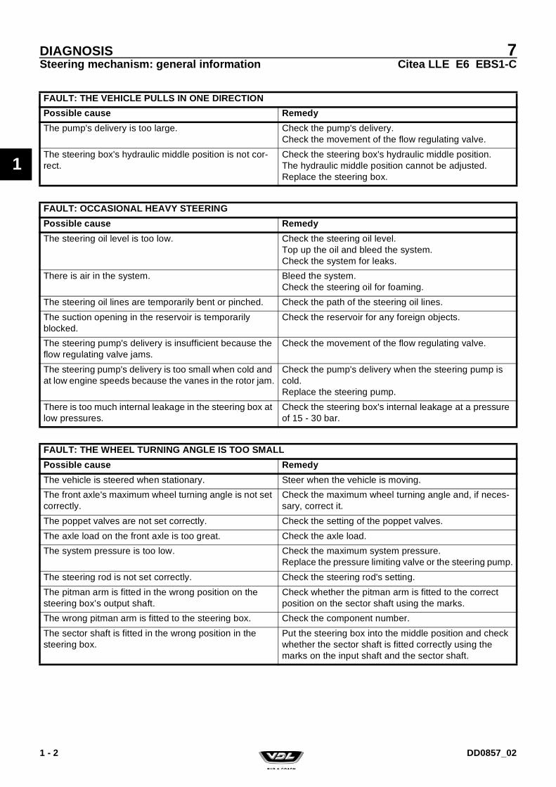
FAULT: THE VEHICLE PULLS IN ONE DIRECTION
Possible cause Remedy
The pump's delivery is too large. Check the pump's delivery.Check the movement of the flow regulating valve.
The steering box's hydraulic middle position is not cor-rect.
Check the steering box's hydraulic middle position.The hydraulic middle position cannot be adjusted.Replace the steering box.
FAULT: OCCASIONAL HEAVY STEERING
Possible cause Remedy
The steering oil level is too low. Check the steering oil level.Top up the oil and bleed the system.Check the system for leaks.
There is air in the system. Bleed the system.Check the steering oil for foaming.
The steering oil lines are temporarily bent or pinched. Check the path of the steering oil lines.
The suction opening in the reservoir is temporarily blocked.
Check the reservoir for any foreign objects.
The steering pump's delivery is insufficient because the flow regulating valve jams.
Check the movement of the flow regulating valve.
The steering pump's delivery is too small when cold and at low engine speeds because the vanes in the rotor jam.
Check the pump's delivery when the steering pump is cold.Replace the steering pump.
There is too much internal leakage in the steering box at low pressures.
Check the steering box's internal leakage at a pressure of 15 - 30 bar.
FAULT: THE WHEEL TURNING ANGLE IS TOO SMALL
Possible cause Remedy
The vehicle is steered when stationary. Steer when the vehicle is moving.
The front axle's maximum wheel turning angle is not set correctly.
Check the maximum wheel turning angle and, if neces-sary, correct it.
The poppet valves are not set correctly. Check the setting of the poppet valves.
The axle load on the front axle is too great. Check the axle load.
The system pressure is too low. Check the maximum system pressure.Replace the pressure limiting valve or the steering pump.
The steering rod is not set correctly. Check the steering rod's setting.
The pitman arm is fitted in the wrong position on the steering box’s output shaft.
Check whether the pitman arm is fitted to the correct position on the sector shaft using the marks.
The wrong pitman arm is fitted to the steering box. Check the component number.
The sector shaft is fitted in the wrong position in the steering box.
Put the steering box into the middle position and check whether the sector shaft is fitted correctly using the marks on the input shaft and the sector shaft.
1 - 2 DD0857_02

7Citea LLE E6 EBS1-C
DIAGNOSISSteering mechanism: general information
1
FAULT: THE VEHICLE PULLS TO ONE SIDE
Possible cause Remedy
The weight has been distributed unequally which makes the vehicle tilt to one side.
Change the weight distribution.
Driving on cambered roads. Allow for the fact that the vehicle can pull to one side when driving on cambered roads.
The tyre pressures in the tyres on the front axle are dif-ferent.
Check the tyre pressure. Inflate both tyres to the speci-fied tyre pressure.
Different types of tyre have been fitted or there is a large difference in the depth of tread on the front axle's tyres.
Always fit the same type of tyres to the same axle which have approximately the same depth of tread.
Different types of wheel rim are fitted to the front axle. Always fit the same type of wheel rim to the same axle.
There is a fault with one of the tyres. Change the tyre on the side to which the vehicle pulls.
The brakes are not correctly adjusted or one of the front axle's brakes drags.
Check the brakes. If necessary, repair the brakes and readjust them.
The steering column's universal joints are not aligned. Check/correct the position of the universal joints in rela-tion to each other.
The wheel bearing play has not been set correctly. Check the wheel bearing's setting. Correctly adjust the wheel bearing play.
The axle tilt is not correct. Check the axle tilt. Adjust the axle tilt correctly.
The camber is not correct. Check the camber.Check the axle beam.
The vehicle is not correctly aligned. Check the alignment of the vehicle.
There is play in the front and/or rear axle mounting. Check the mounting. Replace worn parts.
The pneumatic suspension is set incorrectly. This makes the vehicle tilt.
Check the height control. Correct the height control.
FAULT: THE VEHICLE WANDERS, POOR TRACKING
Possible cause Remedy
The tyre pressure of the steered wheels is too low. Check the tyre pressure.Inflate the tyres to the specified pressure.
The steering box's pressure point is not correctly set; there is play on the pressure point or its adjustment is too heavy.
Check the pressure point setting. Adjust the pressure point correctly.
The load on the front axle is too low. Check the axle load.
The toe-in is not correct. Check the toe-in.Adjust the toe-in correctly.
The axle tilt is not correct. Check the axle tilt.Adjust the axle tilt correctly.
There is play in the bevel box. Check the bevel box.
There is play in one of the steering column's universal joints.One of the universal joints turns heavily.
Check the steering column's universal joints.Replace worn parts.
The universal joints in the steering column are not aligned.
Check/correct the position of the universal joints in rela-tion to each other.
1 - 3DD0857_02

7Citea LLE E6 EBS1-C
DIAGNOSISSteering mechanism: general information
1
There is play in the steering rod’s coupling balls. Check the ball joints.Replace the ball joints.
The steering box, steering bracket or the steering rod's attachment is loose.
Check the attachments and retighten the nuts/bolts.
The swivel axle bearing is worn or turns heavily. Check the swivel axle bearing.Replace worn parts.
The steering rod is not set correctly. When the wheels are in the "straight ahead" position, the steering box is not in the mechanical middle position (pressure point).
Check the steering rod's setting.Adjust the steering rod correctly.
There is play in the front and/or rear axle mounting. Check the axle mounting. Replace worn parts.
The steering pump's delivery is too large. Check the steering pump's delivery.Check the movement of the flow regulating valve.If necessary, replace the steering pump.
There is too much internal friction in the steering box. Check the steering box's slip moment.Replace the steering box.
There is an internal fault in the steering box. Replace the steering box.
FAULT: THE STEERING WHEEL DOES NOT RETURN TO THE STRAIGHT AHEAD POSITION OR ONLY RETURNS SLOWLY
Possible cause Remedy
The front axle tyre pressure is too low. Check the tyre pressure.Inflate the tyres to the specified pressure.
The steering column's universal joints are not aligned. Check/correct the position of the universal joints in rela-tion to each other.
The load on the front axle is too low. Check the axle load.
The axle tilt is not correct. Check the axle tilt.Adjust the axle tilt correctly.
The universal joint or the steering column bearing turns heavily.
Check the universal joints and the steering column’s bearing. Replace worn parts.
The bevel box turns heavily. Check the operation of the bevel box.
The steering mechanism’s mechanical components rub each other (pitman arm, steering rod, steering arm, track rod, track rod arm).
Check the steering mechanism’s mechanical compo-nents.
The steering box or steering bracket is loose. Check the attachments and retighten the bolts.
The swivel axle bearing turns heavily. Check the swivel axle bearing.
The steering pump's delivery is too large. Check the pump's delivery.Check the movement of the flow regulating valve. Replace the pump.
The pressure point is set too heavily. Check the pressure point setting.Adjust the pressure point correctly.
There is too much internal friction in the steering box. Check the steering box's slip moment.Replace the steering box.
There is an internal fault in the steering box. Replace the steering box.
FAULT: THE VEHICLE WANDERS, POOR TRACKING
Possible cause Remedy
1 - 4 DD0857_02

7Citea LLE E6 EBS1-C
DIAGNOSISSteering mechanism: general information
1
FAULT: THE STEERING WHEEL IS JERKY
Possible cause Remedy
There is air in the system. Check the steering oil level and bleed the system.
Worn or loose shock absorbers on the steered axle(s). Correct the attachment.Replace the shock absorbers.
The steering pump's delivery is too low. Check the steering pump's delivery.
The steering rod, track rod, steering bracket or steering box is loose.
Check/repair the attachment of these components.
The internal play in the steering box is too large. Check the steering box's internal play. Replace the steering box.
FAULT: THE STEERING WHEEL VIBRATES
Possible cause Remedy
There is dirt between the wheel rim and the hub. Remove the wheel and clean the wheel rim and the hub.Fit the wheel as described.
The wheel bolts have not been tightened evenly. Unscrew all the bolts and tighten them as described.
A wheel is unbalanced. Balance the wheel statically and dynamically.
FAULT: THERE IS AIR IN THE STEERING OIL
Possible cause Remedy
The oil level in the reservoir is too low. Check the oil level.Top up the oil.Check for leaks.
Poor seal on the suction line connections. Check the connections.Replace the hose and the hose clips.
The suction line is porous. Replace the hose and the hose clips.
The steering pump is not correctly sealed internally. Replace the steering pump.
FAULT: THE STEERING OIL LEAKS
Possible cause Remedy
The delivery line or the return line leaks. Check the lines and line connections.
The delivery line's connection or the return line's connec-tion leaks.
Tighten the lines securely.Replace the lines.
The reservoir leaks. Check the reservoir.
The steering pump leaks. Check the steering pump’s seals and connections.
1 - 5DD0857_02

7Citea LLE E6 EBS1-C
DIAGNOSISSteering mechanism: general information
1
NoiseThe steering mechanism always makes a noise.Normal noises:• A hissing noise in the steering box when steering. The
strength of the noise depends on the system pressure.• An increasing noise when the poppet valve opens.• A maximum noise when the pressure regulating valve
opens.
The steering box leaks. Check the following seals on the steering box.- Input shaft oil seal.- Sector shaft oil seal in the side cover (plastic plug).- Side cover gasket.- Sector shaft oil seal on same side as the pitman arm.- Various plugs.- Poppet valve adjustment bolt.
Depending of the leakage, replace the input shaft oil seal, the sector shaft oil seals, the side cover gasket, the seals of the various plugs and the adjusting bolt.
The steering box must be replaced if there are other leaks.
The grease behind the sector shaft's dust ring or the input shaft’s dust ring has a melting point which is too low.It appears that the steering box is leaking, while in fact the grease has melted.
Replace the grease with grease that has a melting point > 130 °C.
FAULT: THE STEERING OIL LEAKS
Possible cause Remedy
FAULT: THE STEERING PUMP PRODUCES A SHRIEKING NOISE WHEN STEERING
Possible cause Remedy
The oil level is too low, so the steering pump draws in air. Check the oil level.Top up the oil.Check for leaks.
Air in the steering oil. Check the oil for the presence of air (foaming).Bleed the system and trace the cause.
The suction line is bent or pinched. Check the suction line.
The suction opening in the reservoir is (partially) blocked.
Check the suction opening in the reservoir.
FAULT: THE STEERING PUMP PRODUCES A DIFFERENT NOISE WHEN THE ENGINE IDLES. THE STRENGTH OF THE NOISE INCREASES AS THE ENGINE SPEED INCREASES.
Possible cause Remedy
The steering pump is worn. Replace the steering pump.Change the steering oil.Clean the reservoir and the lines.Replace the filter.
1 - 6 DD0857_02

7Citea LLE E6 EBS1-C
DIAGNOSISSteering mechanism: general information
1
FAULT: WHEN STEERING, THE NOISE OF METAL ON METAL CAN BE HEARD
Possible cause Remedy
The steering box, steering bracket or pitman arm is loose.
Check the attachment of the components.Retighten the bolts to the specified torque.
There is play in the coupling ball of the steering rod or track rod.
Check the ball joints.Replace the ball joints.
Parts of the steering mechanism rub against each other. Carefully turn the steering mechanism from stop to stop and check the mechanical components to see whether they rub.
There is play in the steering column’s slip joint. Check the slip joint for wear.Replace the steering rod.
1 - 7DD0857_02

7Citea LLE E6 EBS1-C
DIAGNOSISSteering mechanism: general information
1
1.2 TYRE WEAR DIAGNOSIS
Wear of the treadIs this symptom the result of a technical fault? External fac-tors or improper use can also lead to this fault.Wear of the middle of the tread can also be the result of driv-ing too fast for a long period of time.One of the causes of worn patches on the tread is sudden and heavy braking.
1 - 8 DD0857_02

7Citea LLE E6 EBS1-C
DIAGNOSISSteering mechanism: general information
1
1.2.1 WEAR OF THE TREAD
1.2.2 FEATHER-LIKE WEAR OF THE TREAD
Excessive wear of the tread in the middle of the tread
Possible cause Remedy
The tyre pressure is too high. Check the tyre pressure.
Driving too fast for a long period of time. Check the type of tyre and instruct the driver.
The edge of the profile is feather-like and more worn on one side than the other. The worn edges can be felt when a hand is rubbed over the tread.
Possible cause Remedy
Incorrect toe-in. The feather-like pattern can be felt when rubbing the tyre from the inside to the outside.
Check the toe.
Incorrect toe-out. The feather-like pattern can be felt when rubbing the tyre from the outside to the inside.
Check the toe.
There is a problem with the stability when driving straight ahead.
Check the position of the rear axle.
1 - 9DD0857_02

7Citea LLE E6 EBS1-C
DIAGNOSISSteering mechanism: general information
1
1.2.3 WEAR PATTERNS ON THE TREAD
1.2.4 WEAR ON THE SHOULDER
Wear on the inner shoulder
The tread profile contains areas with excessive wear (there is a knocking sound when driving and vibrations can be felt).
Possible cause Remedy
Damaged or worn mounting components. Check the mounting.
Damaged or worn steering mechanism components. Check the steering mechanism.
Damaged or worn shock absorbers. Check the shock absorbers.
Unbalanced tyre/wheel combination. Check the wheel balance.
Sudden and heavy braking (the wear pattern covers the entire tread).
Inform and instruct the driver.
Separation in the tyre as a result of internal damage, because holes in the road or kerbs have been hit whilst driving with a heavy load or whilst driving fast.
Replace the tyre.
Separation in the tyre as a result of overheating, because the tyre pressure was incorrect whilst driving with a heavy load or whilst driving fast.
Replace the tyre.
The brakes lock. Check the brake system.
The wear only occurs on the inner shoulder. The wear pattern increases the longer the deviation remains pres-ent.
Possible cause Remedy
Too large negative wheel camber. Check the camber.
Too large kingpin inclination. Check the kingpin inclination.
1 - 10 DD0857_02

7Citea LLE E6 EBS1-C
DIAGNOSISSteering mechanism: general information
1
Wear on the outer shoulder
Wear on both shoulders
The wear only occurs on the outer shoulder. The wear pattern increases the longer the deviation remains pres-ent.
Possible cause Remedy
Too large positive wheel camber. Check the camber.
Cornering too fast (the edge of the shoulder has been worn so that it has become rounded).
Check the type of tyre and instruct the driver.
The wear occurs on both the inner and outer shoulder.
Possible cause Remedy
The tyre pressure is too low. Correct the tyre pressure.
1 - 11DD0857_02

7Citea LLE E6 EBS1-C
DIAGNOSISSteering mechanism: general information
1
Cupping
1.2.5 WEAR ON THE WALLS
Cuts
Damage due to knocks
This type of wear almost only ever occurs on non-driven, non-steered axles. The wear pattern results in feather-like wear on the shoulder of the tyre. The worn edges can be felt when a hand is rubbed over the shoulder in the direction of rotation.
Possible cause Remedy
Alignment Check the alignment of the wheels and axles.
Damaged or worn mounting components. Check the axle mounting.
The wall is damaged from the outside to the inside, which may have damaged the tyre body.
Possible cause Remedy
Cuts due to a sharp object. Change the tyre, because the damaged wall may cause a burst tyre after it has been pumped up.
Initial internal damage to the tyre due to a heavy knock that has resulted in separation of the tyre, which has resulted in a lump on the wall.
Possible cause Remedy
A knock against a sharp edge on a stone, kerb or hole in the road.
Change the tyre, because the damaged wall may cause a burst tyre after it has been pumped up.
1 - 12 DD0857_02
7Citea LLE E6 EBS1-C
DIAGNOSISSteering mechanism: general information
1
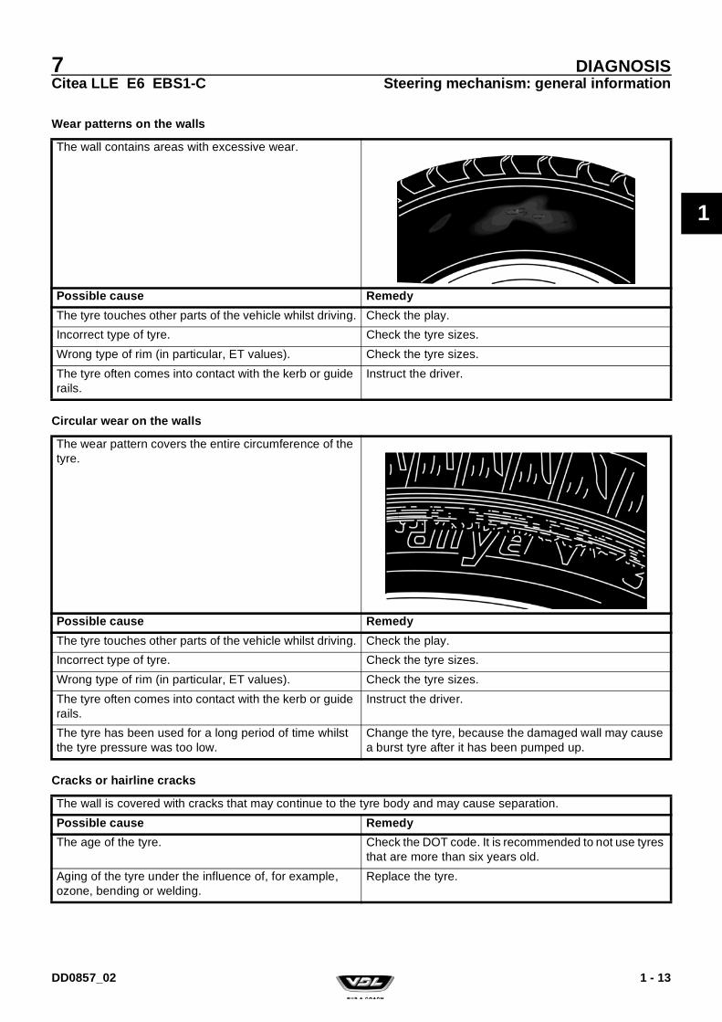
Wear patterns on the walls
Circular wear on the walls
Cracks or hairline cracks
The wall contains areas with excessive wear.
Possible cause Remedy
The tyre touches other parts of the vehicle whilst driving. Check the play.
Incorrect type of tyre. Check the tyre sizes.
Wrong type of rim (in particular, ET values). Check the tyre sizes.
The tyre often comes into contact with the kerb or guide rails.
Instruct the driver.
The wear pattern covers the entire circumference of the tyre.
Possible cause Remedy
The tyre touches other parts of the vehicle whilst driving. Check the play.
Incorrect type of tyre. Check the tyre sizes.
Wrong type of rim (in particular, ET values). Check the tyre sizes.
The tyre often comes into contact with the kerb or guide rails.
Instruct the driver.
The tyre has been used for a long period of time whilst the tyre pressure was too low.
Change the tyre, because the damaged wall may cause a burst tyre after it has been pumped up.
The wall is covered with cracks that may continue to the tyre body and may cause separation.
Possible cause Remedy
The age of the tyre. Check the DOT code. It is recommended to not use tyres that are more than six years old.
Aging of the tyre under the influence of, for example, ozone, bending or welding.
Replace the tyre.
1 - 13DD0857_02

7Citea LLE E6 EBS1-C
DIAGNOSISSteering mechanism: general information
1
1 - 14 DD0857_02

7Citea LLE E6 EBS1-C
STEERING MECHANISM: GENERAL INFORMATION
2
STEERING MECHANISM: GENERAL INFORMATION
DD0857_02

7Citea LLE E6 EBS1-C
STEERING MECHANISM: GENERAL INFORMATION
2
DD0857_02

7Citea LLE E6 EBS1-C
STEERING MECHANISM: GENERAL INFORMATIONSafety regulations
2
1. SAFETY REGULATIONS
1.1 SAFETY REGULATIONS
The steering mechanism is one of the most safety critical components in a vehicle. Always work in a very clean envi-ronment. Even the slightest contamination may cause faults.
Work on the steering mechanism may only be carried out by experienced mechanics who have received the appropriate training.
Carefully check the thread of any attachment aids that are reused.
Tighten all the connections to the specified torque.
Always check the line connections for leaks after tightening.
The steering box must be either inspected by VDL Bus & Coach or replaced if there has been a collision which (may have) affected the steering box or other parts of the steering mechanism. This also applies if no external damage can be observed.The steering box may have suffered internal damage from the collision, making it unreliable.The other steering mechanism components which may have been affected, such as the steering rods, track rods, steering arms, track rod arms, steering bracket, pitman arm, and the attachment of these components should be checked for deformation, cracks, fractures, etc.If possible, they should be magnafluxed.Always replace damaged components, even when in doubt.
Only replace the components with genuine VDL Bus & Coach components.
Do not take any risks. Always replace the components when in doubt.
It is not permitted to carry out welding work on the steering mechanism’s components.
It is not permitted to straighten components of the steering mechanism.
A poorly adjusted pressure point will adversely affect the vehicle's steering characteristics.
Always take a test drive after carrying out work on the steering mechanism. Be aware of the fact that the steering mechanism may not work correctly during a test drive.
1 - 1DD0857_02
7Citea LLE E6 EBS1-C
STEERING MECHANISM: GENERAL INFORMATIONSafety regulations
2
1 - 2 DD0857_02

7Citea LLE E6 EBS1-C
STEERING MECHANISM: GENERAL INFORMATIONGeneral information
2
2. GENERAL INFORMATION
2.1 GENERAL VIEW OF THE HYDRAULIC SECTION
ILAe0355
1. Oil reservoir with return filter 4. Delivery line2. Steering pump suction line 5. Steering box3. Steering pump 6. Return line
2 - 1DD0857_02

7Citea LLE E6 EBS1-C
STEERING MECHANISM: GENERAL INFORMATIONGeneral information
2
2.2 DESCRIPTION OF THE HYDRAULIC SECTION
LayoutThe hydraulic part of the steering mechanism consists of a reservoir (1) with a filter (1a), the steering pump (3) and the steering box (5).
The steering pump (3) is a tandem pump. The front pump is the hydraulic pump for the fan drive and the rear pump is the hydraulic pump for the steering system.
OperationThe oil flows from the oil reservoir (1) to the steering pump (3) through the suction line (2). The steering pump (3) is a gear pump and it pumps the oil through the delivery line (4) to the steering box (5).
The oil flows back to the reservoir (1) from the steering box (5) through the return line (6). There is always a low pressure in the return line. At the maximum pump delivery, approximately 1/3 of the oil passes through the return filter and approximately 2/3 of the oil flows directly back to the oil reservoir (1).
The pressure in the delivery line (4) varies and is dependent on the force used to steer the vehicle. If the vehicle is not steered, then there is a recirculation pressure in the delivery line. When the vehicle is steered, the pressure in the delivery line can increase to the value that the pressure relief valve is set to. This maximum pressure can be reached if the steering wheel is turned while the vehicle is stationary on a rough road surface or when the vehicle is stationary and a wheel touches the kerb. At maximum pressure, there is a large transfer of energy in the steering mechanism, which produces a large amount of heat. If this situation is maintained for too long, the steering pump may be damaged by the heat that is produced.
The steering pump is able to produce a very high pressure for a short period of time. Parts of the steering mechanism may be overloaded or broken off as a result of this very high pressure.
A pressure limiting valve protects the steering mechanism against excessive pressure. The system pressure must not be increased. The pressure limiting valve is located in the steering box. This can be checked by reading the identification plate on the steering box. The component has a pressure limiting valve if a pressure is stated on the identification plate.
ILAe0264
It may be extremely dangerous to replace the steering box or the steering pump with one of a different model and it is, therefore, not permitted to do this without prior permission from VDL Bus & Coach. If the original model is no longer available, VDL Bus & Coach will supply another approved type.
2 - 2 DD0857_02

7Citea LLE E6 EBS1-C
STEERING MECHANISM: GENERAL INFORMATIONInspection and adjustment
2
3. INSPECTION AND ADJUSTMENT
3.1 STEERING SYSTEM: INSPECTING USING A PRESSURE GAUGE
A quick check of the steering mechanism can be made using a pressure gauge.The same gauge that was used to adjust the poppet valves may be used.
Only a limited number of measurements can be made using a manometer.A test box is needed to test the steering pump (delivery l/min at a certain pressure) and the condition of the steering box (internal seals and play).
The steering mechanism must be diagnosed using a test box if the cause of the problem cannot be found using a manom-eter.
Points of attention when connecting the manometer1. Clean the delivery line connection which is to be discon-
nected.
2. Check the attachment of the steering box (see 2 - 3.3 Steering box: checking the attachment (3 - 11)).
3. Check the hydraulic middle position (see 2 - 3.4 Hydraulic middle position: checking (3 - 12)).
4. Place reliable turning plates under the vehicle’s front wheels.
Always check the tightening torque of the steering wheel lock nut after the steering wheel has been tightened using a dial torque spanner.
Block the vehicle so that it cannot slide off the jack or the turning plates.
3 - 1DD0857_02

7Citea LLE E6 EBS1-C
STEERING MECHANISM: GENERAL INFORMATIONInspection and adjustment
2
Connecting the manometer
1. Connect the manometer (VDL Bus & Coach no. 40535653) to the T-piece in the delivery line.Make sure as little steering oil as possible escapes and collect any spilt oil.
2. Check the steering oil level in the reservoir and, if neces-sary, top it up.
3. Bleed the steering mechanism by idling the engine for approx. 2 minutes without moving the steering wheel.
Warming the steering oil to the test temperature1. Set the engine speed to 1,200 - 1,400 rpm.
2. Turn the steering mechanism to its maximum for 5 sec-onds, making sure the pressure does not exceed 50 bar. Do not touch the steering wheel for 5 seconds.
3. Repeat this procedure until the lines are at least warm to the touch.
Measuring the recirculation pressure1. Idle the engine.
2. Check the recirculation pressure. Compare the meas-ured play to the specified value (see 0 - 2.1 Steering box (2 - 1)).
Only use couplings and hoses that are able to withstand the maximum system pressure.
ILAe0160
Make sure the connection of the pressure gauge (1) does not touch the battery cable (2), because this could cause a short circuit!
ILAe0340
3 - 2 DD0857_02

7Citea LLE E6 EBS1-C
STEERING MECHANISM: GENERAL INFORMATIONInspection and adjustment
2
Checking the front axle bearing1. Idle the engine.
2. Turn the steering wheel so that the steering mechanism slowly turns from the middle position to both axle stops.
3. Check whether the control pressure increases steadily.
Testing the maximum system pressure1. Idle the engine.
2. Turn the steering mechanism and place a 15 mm spacer (VDL Bus & Coach no. 40535996) between the adjusting bolt or the stop on the swivel axle and the axle beam stop.
3. Place a dial torque spanner on the steering wheel’s attachment nut.Apply a force of 45 Nm to the torque spanner.
4. Read the maximum pressure on the manometer (the maximum pressure should not be maintained for longer than 5 seconds). Compare the measured play to the specified value (see 0 - 2.1 Steering box (2 - 1)).
Comment:If the measured value deviates from the specified value by more than 10%, the cause must be investigated with the aid of a test box.
5. Repeat the measurement using the 15 mm spacer on the other side of the front axle.
6. Retighten the steering wheel’s attachment nut to the specified torque (see 0 - 5.3 Tightening torques (5 - 3)).
7. Remove the pressure gauge.
8. Check the steering oil level in the reservoir and, if neces-sary, top it up.
9. Bleed the steering mechanism (see 2 - 4.1 Steering mechanism: draining and filling (4 - 1)).
ILAe0021
Be careful when fitting the 15 mm spacer between the adjusting bolt and the axle stop, because parts of your body can easily become trapped.
ILAe0022
3 - 3DD0857_02

7Citea LLE E6 EBS1-C
STEERING MECHANISM: GENERAL INFORMATIONInspection and adjustment
2
3.2 STEERING MECHANISM: INSPECTING USING A TEST BOX
Comment:Using a test box, it is possible:• To inspect the condition of the entire steering mechanism.• To make a reliable diagnosis if the steering mechanism is
not working correctly.
Checking with a pressure gauge only gives information about the pressures in the system. Using a test box also gives infor-mation about the condition of the steering pump (delivery) and the steering box (internal leaks). This results in a more accurate diagnosis and avoids unnecessary replacement of parts.
Electronic test box "Servotest 550"The inspection described below is carried out using the "Servotest 550" test box. The steering mechanism can also be tested with other test equipment that is able to carry out the same measurements as the "Servotest 550".
The test box is connected by hoses in the delivery line between the steering pump and steering box.
A filter is included in the "Eingang" line connection which, depending on the contamination in the oil, should be cleaned at regular intervals.
The "Servotest 550" consists of the following components:
Preparations for connecting the test box1. Check the attachment of the steering box (see
2 - 3.3 Steering box: checking the attachment (3 - 11)).
2. Check the hydraulic middle position (see 2 - 3.4 Hydraulic middle position: checking (3 - 12)).
ILAe0023
1. "Eingang" connection (inlet)2. "Ausgang" connection (outlet)3. "Tank" connection4. Tap5. Non-return valve (Drossel)6. 120/150 bar pressure limiting valve
(switchable)7. Delivery gauge 0.01 - 100 l/min8. Delivery gauge switch9. Low-pressure gauge 0-25 bar10. High-pressure gauge 0-250 bar11. Temperature gauge 0-120 °C
3 - 4 DD0857_02

7Citea LLE E6 EBS1-C
STEERING MECHANISM: GENERAL INFORMATIONInspection and adjustment
2
3. Place reliable turning plates under the vehicle’s steerable wheels.
Connecting the test box1. Check whether the non-return valve (5) of the Servo-
tester 550 is completely closed, the tap (4) is fully open and the pressure regulating valve (6) is set to the maxi-mum system pressure.
2. Clean the delivery line connection which is to be discon-nected.
3. Connect the test box in the delivery line.Make sure as little steering oil as possible escapes. Col-lect the oil that escapes.Connect the hose which is connected to the test box's "Eingang" connection to the hose which comes from the steering pump.Connect the hose which is connected to the test box's "Ausgang" connection to the part of the line that goes to the steering box.
4. Hang the hose which comes from the "Tank" connection into the reservoir. Secure this hose to the reservoir and make sure the end of the hose remains below the surface of the oil (to prevent foaming).
5. Check the steering oil level and, if necessary, top it up.
6. Start the engine and pay attention to the steering oil level.
Block the vehicle so that it cannot slide off the jack or the turning plates.
ILAe0023
Only use couplings and hoses that are able to withstand the maximum system pressure.
ILAe0265
3 - 5DD0857_02

7Citea LLE E6 EBS1-C
STEERING MECHANISM: GENERAL INFORMATIONInspection and adjustment
2
Warming the steering oil to the test temperature1. Bleed the system by idling the engine for 2 minutes.
Regularly check the steering oil level and, if necessary, top it up. Do not turn the steering wheel during this time.
2. Idle the engine.
3. Slowly close the tap (4) until the manometer (10) gives a reading of 50 bar.
4. Wait until the temperature gauge (11) gives a reading of 50° C.
5. Open the tap (4) fully again.
Inspecting the steering mechanism using a test box
Comment• Regularly check the temperature of the steering oil during
the measurements and, if necessary, warm up the oil as described above.
• If a value is recorded during the measurement which is dif-ferent to the specified value, the cause must be traced and rectified before taking the next measurement.
Measuring the recirculation pressure1. Idle the engine.
2. Open the tap (4) fully.
3. The recirculation pressure is given by the manometer (9). Compare the measured value with the maximum permit-ted value (see 0 - 2.1 Steering box (2 - 1)).
Checking the front axle bearing1. Idle the engine.
2. Check whether the tap (4) is fully open.
3. Turn the steering wheel so that the steering mechanism slowly turns from the middle position to both axle stops.
4. Check whether the required regulating pressure increases steadily.
ILAe0023
3 - 6 DD0857_02

7Citea LLE E6 EBS1-C
STEERING MECHANISM: GENERAL INFORMATIONInspection and adjustment
2
Measuring the maximum system pressure1. Idle the engine.
2. Turn the steering mechanism and place a 15 mm spacer (VDL Bus & Coach no. 40535996) between the adjusting bolt and the axle stop.
3. Place a dial torque spanner on the steering wheel nut. Apply a force of 45 Nm to the nut.
4. Read the pressure on the manometer (10) (the maximum pressure should not be maintained for longer than 5 sec-onds). Compare the reading to the specified value (see 0 - 2.1 Steering box (2 - 1)).
5. Repeat the measurement using the 15 mm spacer on the other side of the front axle.
Measuring the maximum wheel deflection limiting pressure1. Turn the steering mechanism as far as possible to one
side.
2. Set the engine speed to 1,200 - 1,400 rpm.
3. Place a dial torque spanner on the steering wheel nut. Apply a force of 45 Nm to the nut.
4. The manometer (10) will indicate the limiting pressure.
5. Compare the measured play to the specified value (see 0 - 2.1 Steering box (2 - 1)).
6. Repeat the measurement on the other side of the axle.
ILAe0021
Be careful when fitting the 15 mm spacer between the adjusting bolt and the axle stop, because parts of your body can easily become trapped.
ILAe0022
ILAe0023
3 - 7DD0857_02

7Citea LLE E6 EBS1-C
STEERING MECHANISM: GENERAL INFORMATIONInspection and adjustment
2
Testing the maximum pump pressure1. Check whether the pressure limiting valve (6) is set to the
correct pressure.
2. Idle the engine and slowly close the tap (4) until the max-imum pressure on the gauge (10) is reached.This maximum pressure must not be maintained for more than 5 seconds.If it is, the pump’s internal components will overheat, which will cause the pump to become worn too quickly. If the pressure limiting valve (6) is set to a pressure which is lower than the system pressure, then the maximum system pressure will not be reached.
3. Open the tap (4).
4. Compare the measured play to the specified value (see 0 - 3. Tandem pump (3 - 1)).
Measuring the pump delivery1. Turn on the delivery gauge (7) using the switch (8).
2. Set the engine speed to 1,200 - 1,400 rpm.
3. Close the tap (4) until the manometer (10) gives the specified pump delivery pressure (see 0 - 3. Tandem pump (3 - 1)).
4. Read the pump delivery on the delivery gauge (7) and compare the value to the specified value (see 0 - 3. Tandem pump (3 - 1)).
Testing the steering pump’s flow limiting valve1. Turn on the delivery gauge (7) using the switch (8).
2. Slowly increase the engine speed until the reading on the delivery gauge (7) no longer increases.Check whether the delivery is stable and compare the measured value to the specified value (see 0 - 2.1 Steering box (2 - 1)).
3. Increase and decrease the engine speed and check whether the delivery increases evenly and then remains constant.
4. Slowly close the tap (4) until the reading on the manom-eter (10) has increased to approximately 50 bar. While closing the tap, check whether the needle on the gauge (1) moves a lot.
ILAe0023
Never turn the steering wheel whilst the tap (4) is closed. The peak pressures may damage the pump or the test box.
3 - 8 DD0857_02

7Citea LLE E6 EBS1-C
STEERING MECHANISM: GENERAL INFORMATIONInspection and adjustment
2
Measuring the steering box’s internal leakage1. Check whether the "Tank" connection and the steering
oil reservoir are connected to each other. To prevent foaming, the hose to the reservoir should reach the bot-tom of the reservoir.
2. Open the non-return valve (5).
3. Close the tap (4) completely.
4. Use the non-return valve (5) to set the pressure to 30 bar less than the maximum system pressure.
5. Open the tap (4) fully.
6. Turn on the delivery gauge (7) using the switch (8).
7. Turn the steering mechanism and place a 15 mm spacer (VDL Bus & Coach no. 40535996) between the adjusting bolt and the axle stop.
8. Place a dial torque spanner on the steering wheel nut. Apply a force of 45 Nm to the nut.
9. Read the volume of leak-off oil and compare it to the maximum permitted volume of leak-off oil (see 0 - 2.1 Steering box (2 - 1)).
10. Repeat the measurement on the other side.
11. Carry out the test again at a pressure of 15-30 bar if the steering mechanism becomes jerky.
Checking the attachment of the steering wheel lock nutRetighten the steering wheel nut to the specified torque (see 0 - 5.3 Tightening torques (5 - 3)), because it may have been loosened by the torque spanner.
Removing the test box1. Remove the hoses and connect the delivery line.
ILAe0023
ILAe0021
Be careful when fitting the 15 mm spacer between the adjusting bolt and the axle stop, because parts of your body can easily become trapped.
ILAe0022
3 - 9DD0857_02

7Citea LLE E6 EBS1-C
STEERING MECHANISM: GENERAL INFORMATIONInspection and adjustment
2
2. Check the steering oil level and, if necessary, top it up.
3. Bleed the system.
4. Check the line connections for leaks.
5. Remove the jack.
3 - 10 DD0857_02

7Citea LLE E6 EBS1-C
STEERING MECHANISM: GENERAL INFORMATIONInspection and adjustment
2
3.3 STEERING BOX: CHECKING THE ATTACHMENT
1. Idle the engine.
2. Pull the steering wheel with short jerks.
3. The steering box must not move.
3 - 11DD0857_02

7Citea LLE E6 EBS1-C
STEERING MECHANISM: GENERAL INFORMATIONInspection and adjustment
2
3.4 HYDRAULIC MIDDLE POSITION: CHECKING
1. Jack up the front axle.
2. Position the hoisting sheers.
3. Place the pitman arm in the middle position.
4. Set the engine speed to 1,200 - 1,400 rpm.
5. The pitman arm must not move by itself.
Use suitable, approved tools to raise the vehicle.
Never work under a vehicle if it is only supported by a jack or by hoisting equipment.Make sure the axle is well supported before commencing work under the vehicle.
ILAe0037
3 - 12 DD0857_02

7Citea LLE E6 EBS1-C
STEERING MECHANISM: GENERAL INFORMATIONInspection and adjustment
2
3.5 STEERING SHAFT UNIVERSAL JOINTS: CHECKING THE ATTACHMENT
1. If necessary, remove the cover at the steering box.
2. Check the universal joints for play. If play can be felt, then the component concerned must be replaced.
3. Check whether play can be felt between the universal joint’s spline connection and the steering box input shaft/ output shaft of the steering column’s bevel. If play can be felt, then the universal joint’s splines and the splines of the steering box input shaft/bevel box out-put shaft must be checked for wear. If wear is found, then the component concerned must be replaced.
4. If, in the case of play, wear is not found, then the attach-ment bolt and the nut must be replaced.Tighten the new (guide) bolt with the self-locking nut to the specified tightening torque (see 0 - 2.2 Tightening torques (2 - 3)).
ILAe0164
3 - 13DD0857_02

7Citea LLE E6 EBS1-C
STEERING MECHANISM: GENERAL INFORMATIONInspection and adjustment
2
3 - 14 DD0857_02

7Citea LLE E6 EBS1-C
STEERING MECHANISM: GENERAL INFORMATIONDraining and filling
2
4. DRAINING AND FILLING
4.1 STEERING MECHANISM: DRAINING AND FILLING
Draining1. Clean the filler cap (2) and the area around it, as well as
the line connections of the steering box, the steering pump and the reservoir.
2. Jack up the front axle.
3. Attach a hose to the steering pump’s drain tap (1).
4. Place a container under the end of the hose.
5. Hang the end of the hose in the container.
6. Remove the filler cap (2) on the oil reservoir.
7. Open the drain tap (1) and drain the oil from the steering mechanism.
To prevent skin damage, avoid unnecessary contact with the oil. When working on hydraulic installations, follow the instructions given in the Dutch Code of Practice NPR-ISO/TR 17165-2.Always read the safety data sheet.
Drain all the steering oil if there is excessive foaming.Trace and repair any leaks, after which the system can be refilled and bled.
ILAe0206
Use suitable, approved tools to raise the vehicle.
Never work under a vehicle if it is only supported by a jack or by hoisting equipment.Make sure the axle is well supported before commencing work under the vehicle.
4 - 1DD0857_02

7Citea LLE E6 EBS1-C
STEERING MECHANISM: GENERAL INFORMATIONDraining and filling
2
8. Place a container under the steering box (1).
9. Remove the return line (2) from the steering box.
10. Remove the steering oil filter element from the steering oil reservoir (2) (see 5 - 3.1 Steering mechanism filter: removing and installing (3 - 1)).
11. Use the starter motor to turn the engine over for approx-imately 10 seconds. When doing so, make sure the engine does not start.
12. Without running the engine, slowly turn the steeringwheel from one axle stop to the other (approx. 6x) until no more oil flows out of the steering box line connection.
13. Reconnect the return line.
14. Close the drain tap on the steering pump.
15. Remove the hose from the drain tap.
16. Replace the steering oil filter element (see 5 - 3.1 Steering mechanism filter: removing and installing (3 - 1)).
Bleeding and filling the steering system
1. The steering box is equipped with an automatic bleeding system. which only works if the system is at the recircu-lation pressure.
ILAe0207
The drained steering oil must not be reused. Keep the hydraulic oil separate from other oil that has been drained and hand it over for disposal to a body that is authorized to dispose of it.
When filling and bleeding, make sure the reservoir is always filled with oil. This will prevent the pump from drawing in air, which in turn will cause the oil to foam.
Air in the hydraulic system can seriously damage the steering pump. It can also cause the steering mechanism to become stuck, either constantly or occasionally.
There is air in the hydraulic system if a shrieking noise can be heard when the steering wheel is turned.
Drain all the steering oil if there is excessive foaming. Trace and repair any leaks, after which the system can be refilled and bled.
4 - 2 DD0857_02
7Citea LLE E6 EBS1-C
STEERING MECHANISM: GENERAL INFORMATIONDraining and filling
2
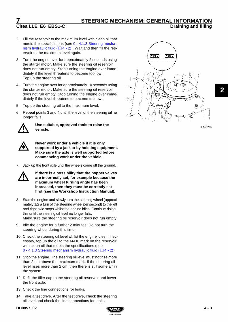
2. Fill the reservoir to the maximum level with clean oil that meets the specifications (see 0 - 4.1.3 Steering mecha-nism hydraulic fluid (4 - 2)). Wait and then fill the res-ervoir to the maximum level again.
3. Turn the engine over for approximately 2 seconds using the starter motor. Make sure the steering oil reservoir does not run empty. Stop turning the engine over imme-diately if the level threatens to become too low.Top up the steering oil.
4. Turn the engine over for approximately 10 seconds using the starter motor. Make sure the steering oil reservoir does not run empty. Stop turning the engine over imme-diately if the level threatens to become too low.
5. Top up the steering oil to the maximum level.
6. Repeat points 3 and 4 until the level of the steering oil no longer falls.
7. Jack up the front axle until the wheels come off the ground.
8. Start the engine and slowly turn the steering wheel (approxi-mately 1/2 a turn of the steering wheel per second) to the left and right axle stops whilst the engine idles. Continue doing this until the steering oil level no longer falls.Make sure the steering oil reservoir does not run empty.
9. Idle the engine for a further 2 minutes. Do not turn the steering wheel during this time.
10. Check the steering oil level whilst the engine idles. If nec-essary, top up the oil to the MAX. mark on the reservoir with clean oil that meets the specifications (see 0 - 4.1.3 Steering mechanism hydraulic fluid (4 - 2)).
11. Stop the engine. The steering oil level must not rise more than 2 cm above the maximum mark. If the steering oil level rises more than 2 cm, then there is still some air in the system.
12. Refit the filler cap to the steering oil reservoir and lower the front axle.
13. Check the line connections for leaks.
14. Take a test drive. After the test drive, check the steering oil level and check the line connections for leaks.
ILAe0205Use suitable, approved tools to raise the vehicle.
Never work under a vehicle if it is only supported by a jack or by hoisting equipment.Make sure the axle is well supported before commencing work under the vehicle.
If there is a possibility that the poppet valves are incorrectly set, for example because the maximum wheel turning angle has been increased, then they must be correctly set first (see the Workshop Instruction Manual).
4 - 3DD0857_02

7Citea LLE E6 EBS1-C
STEERING MECHANISM: GENERAL INFORMATIONDraining and filling
2
4 - 4 DD0857_02

7Citea LLE E6 EBS1-C
STEERING BOX
3
STEERING BOX
DD0857_02

7Citea LLE E6 EBS1-C
STEERING BOX
3
DD0857_02

7Citea LLE E6 EBS1-C
STEERING BOXSafety regulations
3
1. SAFETY REGULATIONS
1.1 SAFETY REGULATIONS
The steering box must be either inspected by VDL Bus & Coach or replaced if there has been a collision which (may have) affected the steering box or other parts of the steering mechanism. This also applies if no external damage can be observed. The steering box may have suffered internal dam-age from the collision, which will make it unreliable.
If the pitman arm has been subjected to an extremely high load (e.g. an accident), it must be magnafluxed, even if no deviations can be observed.
If this is not possible, the pitman arm must be replaced.
The pitman arm may only be removed using the specified special tools. Under no circumstances should the pitman arm be removed by dislodging it with a hammer or by heating it if the specified tools are not available. This would not only result in the pitman arm becoming unreliable, but the sector shaft would also be permanently damaged.
For steering boxes, it is only permitted to replace the input shaft oil seal, the sector shaft oil seals, the dirt and water seals and the side cover’s gasket.
1 - 1DD0857_02

7Citea LLE E6 EBS1-C
STEERING BOXSafety regulations
3
1 - 2 DD0857_02

7Citea LLE E6 EBS1-C
STEERING BOXGeneral information
3
2. GENERAL INFORMATION
2.1 GENERAL VIEW OF THE STEERING BOX
ILAe0025
1. Torsion bar attachment pin2. Input shaft3. Pressure limiting valve4. Cover5. Torsion bar6. Control valve7. Sleeve8. Torsion bar attachment pin9. Poppet valve10. Ball nut11. Sector shaft12. Worm shaft13. Piston14. Poppet valve15. Housing16. Bolt17. Poppet valve adjusting bolt
2 - 1DD0857_02

7Citea LLE E6 EBS1-C
STEERING BOXGeneral information
3
2.2 DESCRIPTION OF THE OPERATION
ILAe0026
ILAe0027
2 - 2 DD0857_02

7Citea LLE E6 EBS1-C
STEERING BOXGeneral information
3
Hydraulic power steeringThe oil flow in the steering box is controlled by the control valve (6). The control valve (6) consists of a sleeve (7) attached to the input shaft (2) and the chamber in the worm shaft (12). There are a number of recesses on the outside of the sleeve (7). The delivery and return lines and the ducts to the cylinder halves end in the chamber in the worm shaft (12).The recesses in the sleeve (7) allow the delivery and return lines to be connected with the ducts to the cylinder halves.If the sleeve (7) is turned in relation to the chamber in the worm shaft (12), one cylinder half is connected to the delivery line and the other half to the return line.If the input shaft (2) is turned the other way, the sleeve (7) will swap over the delivery and return line connections to the cyl-inder halves.
When steering takes place, the control valve (6) increases the oil flow to one side of the piston and connects the other side of the piston to the return line so that the oil can no longer circulate through the steering box. As a result, pres-
ILAe0028
2 - 3DD0857_02

7Citea LLE E6 EBS1-C
STEERING BOXGeneral information
3
sure builds up on one side of the piston and the piston moves.
The piston (13), therefore, does not move. This is called the steering box’s “hydraulic middle position”. The oil pressure at that moment is called the recirculation pressure.The steering box’s neutral position is set at the factory and cannot be altered.
A torsion bar (5) is connected to the input shaft (2) and the worm shaft (12) by pins (1 and 8).When steering takes place, the input shaft (2) turns in rela-tion to the worm shaft (12), resulting in a twisting movement of the torsion bar (5). The torsion bar (5) ensures that when a torque is no longer applied to the input shaft (i.e. when there is no steering), the input shaft (2) is returned to its neu-tral position in relation to the worm shaft (12). As a result, the control valve (6) also returns to its neutral position and the hydraulic power steering is deactivated.
Pressure limitingThe pressure limiting valve (3) protects the system against a system pressure that is too high.
ILAe0025
2 - 4 DD0857_02

7Citea LLE E6 EBS1-C
STEERING BOXGeneral information
3
If the valve’s preset pressure is reached, the valve opens and connects the delivery line to the return line.
Bleed openingThe steering box is self-bleeding.At the recirculation pressure, the steering box is bled auto-matically.The bleed opening is closed at a higher system pressure.
Wheel deflection limitTwo poppet valves (3 and 8) are fitted in the piston to reduce the system pressure at the maximum wheel turning angle.The poppet valves’ pins (2 and 9) touch their stops before the maximum wheel deflection is reached.The pin opens the valve (5) and both cylinder halves become connected, causing the system pressure to decrease.The pin (2) of poppet valve (3) touches the cover (1) and the pin (9) of poppet valve (8) touches the adjusting bolt (10).A new steering box’s poppet valves are adjusted automati-cally.The poppet valves are fitted in the piston using tension bushes (4), which makes it possible for the valves to slide in the piston.On a new steering box, the poppet valves protrude far enough from the cylinder to touch the axle stops (the cover
ILAe0030
2 - 5DD0857_02

7Citea LLE E6 EBS1-C
STEERING BOXGeneral information
3
and the adjusting bolt) well before the maximum wheel deflection is reached.
The first time the steering box is turned to its maximum deflection (both to the left and the right) - with a front axle that is correctly set to the maximum wheel turning angle - the poppet valves are pushed to the correct depth in the piston, so that the valves are correctly adjusted.
If the wheel deflection is to be reduced (e.g. because wider tyres have been fitted), then the poppet valves must be adjusted.This is carried out as follows:• Place the steering box in the middle position and screw the
adjusting bolt (10) further into the steering box.• Moving the piston towards the adjusting bolt (10) will cause
the poppet valve (8) to touch the adjusting bolt (10), so that the valve (8) is pushed deeper into the piston. A distance pin (7) is fitted between the poppet valves (3 and 8).When the valve (8) is pushed deeper into the cylinder, the valve touches the pin (7), and the pin pushes the valve (3) partially out of the piston.
• By moving the piston in the direction of the cover (1) to the maximum wheel turning angle, the poppet valve (3) touches the cover and the valve is pushed into the piston to the correct depth. The valve (3) is then set correctly again. During this action, the poppet valve (8) is partially pushed out of the piston.
• The poppet valve (8) is then correctly set using the adjust-ing bolt (10).
2 - 6 DD0857_02

7Citea LLE E6 EBS1-C
STEERING BOXGeneral information
3
Mechanical transmissionIn the event of failure of the hydraulic power steering, the torque applied to input shaft (2) is transmitted mechanically to the steering rod. The input shaft (2) and the worm shaft (12) can rotate in relation to each other. This rotation is lim-ited by a stop.When steering without hydraulic power steering, the steering power applied to the input shaft (2) is transmitted to the worm shaft (12) by the stop. The ball nut (10) converts the worm shaft’s rotational movement into linear movement of the pis-ton (13).The teeth on the piston (13) rotate the sector shaft (11) and the pitman arm which is attached to it.
BacklashSince the teeth on the sector shaft (11) and the piston (13) remain constantly engaged when driving straight ahead, light wear will occur. This could cause backlash. Backlash can be rectified by axially adjusting the sector shaft with an adjusting bolt. This presses the sector shaft’s (11) slanting teeth deeper into the piston’s (13) teeth, eliminating any backlash.
ILAe0025
2 - 7DD0857_02

7Citea LLE E6 EBS1-C
STEERING BOXGeneral information
3
The sector shaft’s (11) gearing is designed so that the tooth which engages the piston’s teeth when the steering box is in the middle position is slightly higher than the other teeth. This is necessary to avoid the piston jamming in other positions after adjusting the backlash in the steering box’s middle posi-tion. As a result, play can be felt when the steering box is not in the middle position.
2 - 8 DD0857_02

7Citea LLE E6 EBS1-C
STEERING BOXInspection and adjustment
3
3. INSPECTION AND ADJUSTMENT
3.1 POPPET VALVES: INSPECTING AND ADJUSTING
Before connecting the pressure gauge1. Check the attachment of the steering box.
2. Check the hydraulic middle position.
Inspecting the poppet valves1. Connect the manometer (VDL Bus & Coach no.
40535653) to the T-piece in the delivery line.To prevent air from entering the system, make sure the manometer is connected as quickly as possible.Check the level of the steering oil in the reservoir after connecting the manometer and, if necessary, top it up.
2. Bleed the steering mechanism. To do so, idle the engine for approx. 2 minutes without moving the steering wheel.
3. Place axle supports under the vehicle so that the wheels can rotate freely.
4. Heat the steering oil as described below until the lines are at least warm to the touch.• Set the engine speed to 1,200 - 1,400 rpm.• Turn the steering mechanism to its maximum for 5 sec-
onds, making sure that the pressure does not exceed 50 bar.
• Do not touch the steering wheel for 5 seconds.• Continue this operation until the desired temperature is
reached.
To prevent skin damage, avoid unnecessary contact with the oil.
Block the vehicle so that it cannot slide off the jack.
Only use couplings and hoses that are able to withstand the maximum system pressure.
ILAe0160
Considerably higher pressures will be measured if the steering oil is too cold.
3 - 1DD0857_02

7Citea LLE E6 EBS1-C
STEERING BOXInspection and adjustment
3
5. Turn the steering wheel as far as possible to the left.
6. Set the engine speed to 1,200 - 1,400 rpm.
7. Place a dial torque spanner on the steering wheel nut. Apply a force of 45 Nm to the nut.
8. The manometer will give the limiting pressure. Compare the measured value with the stated maximum permitted value (see 0 - 2. Steering box and steering mechanism (2 - 1)). The poppet valves must be reset if the measured value is too high.
9. Carry out the measurement again with the wheel turned as far as possible to the right.
10. Remove the axle supports.
11. Remove the pressure gauge.
12. Check the steering oil level in the reservoir after remov-ing the manometer and, if necessary, top it up.
13. Bleed the steering mechanism. To do so, idle the engine for approx. 2 minutes without moving the steering wheel.
14. Retighten the steering wheel nut to the specified torque (see 0 - 2.2 Tightening torques (2 - 3)).
Adjusting the poppet valvesThere are three adjustment procedures.
Procedure A (automatic adjustment) may only be used if:• A new or overhauled steering box is fitted and the steering
box’s input shaft has not been rotated more than 1.5 revo-lutions at the moment that the steering rod is not yet con-nected to the steering mechanism.
Procedure B (automatic adjustment) may only be used if:• The wheel turning angle has been increased and the pop-
pet valves have never been adjusted using procedure C.
Procedure C (manual adjustment) may only be used if:• The wheel turning angle has been decreased.• The wheel turning angle has been increased and the pop-
pet valves have already been adjusted once using proce-dure C.
• The steering box’s input shaft has been rotated more than 1.5 revolutions before the steering box is connected to the steering mechanism using the steering rod.
ILAe0022
A steering box whose poppet valves have already been adjusted using procedure C can be recognised by the fact that the factory-applied layer of paint is missing from the adjusting bolt’s protruding thread.
3 - 2 DD0857_02

7Citea LLE E6 EBS1-C
STEERING BOXInspection and adjustment
3
Adjustment using procedure A
1. Make sure the steering box’s attachment bolts have been tightened to the specified torque (see 0 - 2.2 Tightening torques (2 - 3)).
2. Check the front axle’s wheel turning angle before fitting the steering rod. If necessary, correct the wheel turning angle using the stop bolts on the swivel axles.
3. Fit the steering rod.
4. Idle the engine.
5. Turn the steering wheel as far as possible to the left and right.Both poppet valves have now been pushed to the correct position in the steering box’s piston and have set them-selves.
6. Turn the engine off.
Adjustment using procedure B1. Make sure the vehicle is unloaded.
2. Idle the engine.
3. Turn the steering wheel as far as possible to the left and right.
4. Turn the engine off.
5. Both poppet valves have now been pushed to the correct position in the steering box’s piston and have set them-selves.
The steering shaft (input shaft) must not be turned more than 1.5 revolutions from the middle position before the steering box is in its definite position and the steering rod is connected. Otherwise, the poppet valves could be pushed too far into the piston.
3 - 3DD0857_02

7Citea LLE E6 EBS1-C
STEERING BOXInspection and adjustment
3
Adjustment using procedure C
1. Screw the adjusting bolt (3) together with a new sealing ring (1) into the steering box until approx. 25 mm of thread protrudes from the lock nut (2).Tighten the lock nut.
If the steering box already has an adjusting screw (3), remove the lock nut (2) with the sealing ring (1) and clean the thread.Fit a new sealing ring and tighten the lock nut.
2. Jack up the vehicle by the front axle and put the wheels in the "middle" position. Support the front axle so that it is at the driving height.
3. Remove the steering rod from the front axle.
The adjustment procedure given below is only for an adjusting bolt which is 65 mm long. If the adjusting bolt is 55 mm long, then 10 mm must be subtracted from all the lengths given.
The poppet valves must be adjusted whilst the vehicle is unloaded!
To adjust the poppet valves, the sealing plug must be replaced by an adjusting bolt. The required adjusting bolt (length 65 mm) can be ordered via VDL Bus & Coach no. 41306317.
ILAe0091
3 - 4 DD0857_02

7Citea LLE E6 EBS1-C
STEERING BOXInspection and adjustment
3
4. Connect the pressure gauge (special tool VDL Bus & Coach no. 40535653) to the test connection in the deliv-ery line. To prevent air from entering the system, make sure the manometer is connected as quickly as possible.Check the level of the steering oil in the reservoir after connecting the manometer and, if necessary, top it up.
5. Bleed the steering mechanism. To do so, idle the engine for approx. 2 minutes without turning the steering wheel.
6. Heat the steering oil as described below until the lines are at least warm to the touch.• Set the engine speed to 1,200 - 1,400 rpm.• Turn the steering mechanism to its maximum for 5 sec-
onds, making sure that the pressure does not exceed 50 bar.
• Do not touch the steering wheel for 5 seconds.• Continue this operation until the required temperature
is reached.
7. Stop the engine.
8. Screw the adjusting bolt (3) into the steering box until the top of the adjusting bolt is flush with the top of the lock nut (2).
Tighten the lock nut to the specified torque (see 0 - 2.2 Tightening torques (2 - 3)).
ILAe0160
Considerably higher pressures will be measured if the steering oil is too cold.
ILAe0032
Sometimes it may be necessary to move the sector shaft (pitman arm) slighty out of the “middle” position so as to allow the hexagonal stud bolt to fall into the poppet valve. Remember to return the steering wheel to the "middle" position.
The following actions can differ for left-hand and right-hand drive (LHD and RHD) vehicles. In that case, the RHD situation is described between brackets.
3 - 5DD0857_02

7Citea LLE E6 EBS1-C
STEERING BOXInspection and adjustment
3
9. With the engine not running, turn the steering wheel as far as possible to the right (RHD: to the left) until resist-ance is felt.This will cause the piston to move towards the poppet valve adjusting bolt.
10. Place a torque spanner on the steering wheel nut and turn the steering mechanism further until a tightening torque of 50 Nm is achieved.This will push the poppet valves into the “reset” position.
11. Remove the torque spanner and turn the steering mech-anism to the middle position.
12. Fit the steering rod.
13. Unscrew the lock nut and unscrew the adjusting bolt 25-27 mm out of the lock nut.
14. Next, tighten the lock nut to a torque of 20 - 30 Nm. Make sure the adjusting bolt does not turn.
15. Start the engine and allow it to idle.
ILAe0033
ILAe0034
ILAe0092
3 - 6 DD0857_02

7Citea LLE E6 EBS1-C
STEERING BOXInspection and adjustment
3
16. Turn the steering wheel as far as possible to the left (RHD: as far as possible to the right) until the stop is reached. Fit a torque spanner to the steering wheel nut and pull with a torque of 35 Nm on the torque spanner. The manometer reading must not exceed 80 bar.This will correctly readjust the poppet valve, which has its stop against the steering box cover.
17. Idle the engine and turn the steering wheel clockwise as far as possible until the stop is reached.The pressure should not exceed approx. 100 bar; this pressure should not be maintained for more than 5 sec-onds.
18. Slacken the lock nut one turn whilst the steering wheel touches the stop and screw the adjusting bolt in whilst keeping the lock nut in position.Screw the adjusting bolt in until the pressure is reduced to a maximum of 80 bar. This will correctly readjust the poppet valve, which has its stop against the adjusting bolt.
19. Set the engine speed to 1,200 - 1,400 rpm. The maxi-mum limiting pressure should not exceed 80 bar. Screw the adjusting bolt in further if the pressure is too high.
20. Tighten the lock nut to the specified torque (see 0 - 2.2 Tightening torques (2 - 3)).
21. Turn the steering wheel anticlockwise as far as possible (RHD: clockwise) until the stop is reached. Set the engine speed to 1,200 – 1,400 rpm and check the limiting pressure.
ILAe0035
ILAe0036
Do not screw the adjusting bolt in further than necessary, because the previously reached setting for the other poppet valve could be lost and the adjustment procedure will then have to be repeated from the beginning.
There is also the chance that the poppet valve will open too early, so that the pressure will reduce too fast and the maximum wheel turning angle will not be reached.
3 - 7DD0857_02

7Citea LLE E6 EBS1-C
STEERING BOXInspection and adjustment
3
22. Measure the length of the adjusting bolt that protrudes from the steering box (distance A in diagram). The total length (including the nut) should not exceed 31 mm.If the adjusting bolt protrudes further from the steering box than the permitted length, an adjusting bolt of the wrong length has been used or the poppet valves have been incorrectly set.In that case, measure the total length of the adjusting bolt and repeat the adjustment procedure.
23. Remove the jack.
24. Remove the pressure gauge.
25. Check the steering oil level in the reservoir after remov-ing the manometer and, if necessary, top it up.
26. Bleed the steering mechanism. To do so, idle the engine for approx. 2 minutes without turning the steering wheel.
27. Retighten the steering wheel nut to the specified torque (see 0 - 2.2 Tightening torques (2 - 3)).
ILAe0093
In order to keep a sufficient screw thread length in the housing, the adjusting bolt should not protrude more from the steering box than specified.A larger distance could result in the loss of the bolt and, therefore, the loss of steering power.
3 - 8 DD0857_02

7Citea LLE E6 EBS1-C
STEERING BOXInspection and adjustment
3
3.2 PRESSURE POINT: INSPECTING AND ADJUSTING
Inspect.1. Place the sector shaft in the “middle” position by aligning
the marks on the sector shaft and the input shaft with the marks on the steering box.
2. Remove the steering rod from the pitman arm (see 8 - 3.2 Steering rod: removing and installing (3 - 5)).
3. Use the marks to check whether the sector shaft is still in the middle position.
4. Take hold of the pitman arm and carefully move the pit-man arm in its direction of rotation to feel whether there is any play. Make sure the input shaft is not rotated more than 1.5 revolutions from the middle position.There must be no play when the steering box is in the middle position. Play is permitted, however, when the steering box is not in the middle position.
5. If play is felt, then the pressure point must be adjusted.
ILAe0037
When a steering rod has been removed, the steering box’s input shaft must not be rotated more than 1.5 revolutions from the middle position, otherwise the poppet valve settings will be changed.
ILAe0165
3 - 9DD0857_02

7Citea LLE E6 EBS1-C
STEERING BOXInspection and adjustment
3
Adjusting the pressure point1. Use the marks to check whether the sector shaft is still in
the middle position.
2. Unscrew the lock nut (2) one turn.
3. Unscrew the adjusting bolt (1) one turn so that play can be clearly felt.
4. Slowly tighten adjusting bolt (1) clockwise until no more play can be felt on the pitman arm. The torque used should not exceed 15 Nm.
5. Turn the adjusting bolt 1/4 to 1/2 of a turn to the right.
6. Tighten the lock nut (2) to the specified torque (see 0 - 2.2 Tightening torques (2 - 3)). Make sure the adjusting bolt (1) does not turn as well.
7. Check whether the play has been removed from the pit-man arm. You should not feel any play for 1/4 of a turn to the left and right from the input shaft’s middle position.
8. If play can still be felt, the adjustment procedure must be repeated.
9. Fit the steering rod on to the pitman arm.
10. Take a test drive and check whether the vehicle remains on the intended course. Also check whether the steering wheel returns to the middle position after turning a cor-ner.
ILAe0038
If the adjusting bolt is tightened too much, the steering wheel will not return to the middle position by itself after cornering. The steering force around the middle position will increase and the directional stability of the vehicle will deteriorate.
3 - 10 DD0857_02

7Citea LLE E6 EBS1-C
STEERING BOXInspection and adjustment
3
3.3 SECTOR SHAFT OIL SEAL: CHECKING FOR LEAKS
1. A plastic plug (3) has been fitted in the side cover.
2. If oil leaks from this plug, then the sector shaft oil seal in the side cover is leaking.
3. If there is a leak, replace the sector shaft oil seal in the steering box’s side cover.
4. Check the sector shaft oil seal on the pitman arm side.
5. If there is a leak, replace the sector shaft oil seal on the pitman arm side.
ILAe0228
It is not permitted:To fit the plastic plug into the side cover using a sealing compound or glue.
To apply an additional layer of paint over the factory-applied paint.
To seal the plug hole using any means other than the plug itself.
If the leaking oil which originates from the sector shaft oil seal cannot escape via the plug hole, there is a chance that the steering box will no longer work.
3 - 11DD0857_02

7Citea LLE E6 EBS1-C
STEERING BOXInspection and adjustment
3
3.4 STEERING BOX: CHECKING THE INTERNAL RESISTANCE
Checking the internal resistance1. Place a container under the steering box.
Clean the line connections and remove the steering oil hoses from the steering box.Collect the oil that is released and plug the line openings.
2. Turn the steering wheel from one stop to the other until no more oil escapes from the steering box. The line con-nections on the steering box should not be plugged.
3. Remove the steering rod from the pitman arm.
4. Remove the steering shaft from the steering box’s input shaft.
5. Place a resistance torque gauge on the steering box’s input shaft and measure the resistance torque in both directions from the middle position up to a maximum of 1.5 revolutions.
6. Compare the measured value with the maximum permit-ted value (see 0 - 2. Steering box and steering mechanism (2 - 1)).
7. The pressure point setting must be checked if a deviating value is measured.
8. Fit the steering oil hoses to the steering box.
9. Fit the steering shaft to the steering box’s input shaft. The groove (A) in the coupling must be aligned with the mark (B) on the steering box's input shaft.
10. Fit a new, original nut and bolt in the universal joint. Tighten the bolt to the specified torque (see 0 - 2.2 Tightening torques (2 - 3)).
11. Fit the steering rod to the pitman arm.
12. Fill and bleed the steering mechanism.
13. If there is a chance that the steering box’s input shaft may have been rotated more than 1.5 revolutions (counted from the middle position) when the steering shaft was removed, then the maximum limiting pressure must be checked.
14. Take a test drive. Check the operation of the steering mechanism. Check the system for leaks after taking the test drive.
When a steering rod has been removed, the steering box’s input shaft must not be rotated more than 1.5 revolutions from the middle position, otherwise the poppet valve settings will be changed.
The internal resistance outside the pressure point cannot be adjusted.
ILAe0040
Check whether the steering shaft has been correctly fitted to the input shaft, so that the bolt can be fitted in the recess (C).
3 - 12 DD0857_02
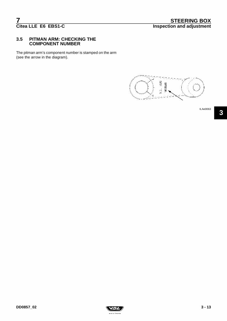
7Citea LLE E6 EBS1-C
STEERING BOXInspection and adjustment
3
3.5 PITMAN ARM: CHECKING THE COMPONENT NUMBER
The pitman arm’s component number is stamped on the arm (see the arrow in the diagram).
ILAe0063
3 - 13DD0857_02
7Citea LLE E6 EBS1-C
STEERING BOXInspection and adjustment
3
3 - 14 DD0857_02

7Citea LLE E6 EBS1-C
STEERING BOXRemoval and installation
3
4. REMOVAL AND INSTALLATION
4.1 STEERING BOX: REMOVING AND INSTALLING THE COMPLETE STEERING BOX
Removing the steering box1. Clean the steering box and its surrounding area.
2. Put the steering mechanism in the middle position.This can be checked using the marks on the steering box.
3. Disconnect the steering oil hoses from the steering box. Collect the oil that escapes and plug the openings in the lines and on the steering box to prevent dirt from enter-ing.
4. Remove the steering rod (5) from the pitman arm (4).
5. Remove the steering shaft (3) from the steering box’s input shaft.
6. Unscrew the bolts (1) of the steering box (2) a couple of turns.
7. Remove the attachment bolts (1) from the steering box and remove the steering box from the vehicle. Save the
The steering box must be either inspected by VDL Bus & Coach or replaced if there has been a collision which (may have) affected the steering box or other parts of the steering mechanism. This also applies if no external damage can be observed. The steering box may have suffered internal damage from the collision, which will make it unreliable.
ILAe0037
If there is a chance that the line connections may be swapped over, then they must be marked.
ILAe0166
When a steering rod has been removed, the steering box’s input shaft must not be rotated more than 1.5 revolutions from the middle position. Otherwise, the poppet valves’ setting will be changed.
The weight of the steering box is approx. 30 kg (dry weight). The steering box should be safely supported.
4 - 1DD0857_02

7Citea LLE E6 EBS1-C
STEERING BOXRemoval and installation
3
bolts that are removed so that you are able to check the length of the new bolts.
Installing the steering box1. Carefully clean and inspect the threaded holes on the
steering box.
2. Remove all paint, dirt, etc. from the steering box's contact surfaces (a thin, factory-applied layer of paint is permit-ted).The contact surfaces should be completely free of dirt and grease.
3. If a new or overhauled steering box is fitted, fit the screw coupling. Tighten the couplings to the specified torque (see 0 - 2.2 Tightening torques (2 - 3)).
4. Replace the attachment bolts. Since the yield point is exceeded when the bolt is tightened, it is no longer safe to reuse the bolts.Use the bolts which have been removed to check whether the new bolts are exactly the same length. Apply a small amount of lubricant to the new bolts. Do not apply too much lubricant, because this might cause the con-nection to become loose.
5. Fit the attachment plate. Fit the steering box (2) together with the pitman arm into the vehicle and tighten the attachment bolts by hand.
6. Tighten the attachment bolts evenly. Tighten the bolts to the specified torque (see 0 - 2.2 Tightening torques (2 - 3)).
7. Fit the steering shaft to the steering box’s input shaft. The groove (A) in the coupling must be aligned with the mark (B) on the steering box's input shaft.
8. Fit a new, original nut and bolt in the universal joint. Tighten the bolt to the specified torque (see 0 - 2.2 Tightening torques (2 - 3)).
9. Fit the steering oil hoses to the steering box.
10. Fit the steering rod.
11. Fill and bleed the steering mechanism (see 2 - 4.1 Steering mechanism: draining and filling (4 - 1)).
12. Set the poppet valves when installing a new or over-hauled steering box (see 0 - 2.1 Steering box (2 - 1)). If there is a chance that the steering box’s input shaft may
Carefully check the length of the new bolts. If the steering box is fitted using bolts which are too long, they can get stuck in the steering box so that there is insufficient pretension.
ILAe0040
Check whether the steering shaft has been correctly fitted to the input shaft, so that the bolt can be fitted in the recess (C).
4 - 2 DD0857_02

7Citea LLE E6 EBS1-C
STEERING BOXRemoval and installation
3
have been rotated more than 1.5 revolutions (counted from the middle position) when the steering rod was removed, then the poppet valves must be checked (see 0 - 2.1 Steering box (2 - 1)).
13. Take a test drive. Check the operation of the steering mechanism. Check the system for leaks after taking the test drive.
4 - 3DD0857_02

7Citea LLE E6 EBS1-C
STEERING BOXRemoval and installation
3
4.2 PITMAN ARM: REMOVING AND INSTALLING
Removing the pitman arm1. Clean the steering box.
2. Clean the sector shaft’s screw thread that protrudes from the nut.
3. Tap the nut’s lock ring back from its locking position.
4. Remove the nut from the sector shaft.
5. Fit the thrust piece (D) into the hydraulic extractor (A) (VDL Bus & Coach no. 40535891).
6. Screw the adaptor (B) (VDL Bus & Coach no. 40694786) partly on to the hydraulic extractor (A).
ILAe0042
If the pitman arm has been subjected to an extremely high load (e.g. an accident), it must be magnafluxed, even if no deviations can be observed. If this is not possible, the pitman arm must be replaced.
The pitman arm may only be removed using the specified special tools.Under no circumstances should the pitman arm be removed by dislodging it with a hammer or by heating it if the specified tools are not available. This would not only result in the pitman arm becoming unreliable, but the sector shaft would also be permanently damaged.
ILAe0255
Pitman arm extractorA. 40535891B. 40694786C. 40694916
4 - 4 DD0857_02

7Citea LLE E6 EBS1-C
STEERING BOXRemoval and installation
3
7. Slide the claw (C) (VDL Bus & Coach no. 40694916) over the pitman arm (1). If necessary, cut through the sector shaft dust seal (2) and remove it.
8. Slide the adaptor (B) with the hydraulic extractor (A) into the claw (C).
9. Screw the spindle (D) of the hydraulic extractor (A) out as far as possible and use an open-end spanner to screw the hydraulic extractor (A) as far as possible into the adaptor (B).
10. Screw the spindle (D) in until the pitman arm comes off the sector shaft.If the pitman arm still has not come off after the spindle has been completely screwed in, screw the spindle out and screw the extractor as far as possible into the adap-tor (B). Next, screw the spindle (D) in again until the pit-man arm comes off the sector shaft.
Installing the pitman arm1. Fit a new dust seal on to the sector shaft.
2. Apply grease which meets the specifications (melting point > 130 °C) to the face of the dust ring that lies against the steering box.
3. Fit the pitman arm on to the sector shaft so that the mark-ings on the pitman arm and the sector shaft are aligned.
If there are two marks on the pitman arm with the letters L and R, then for left-hand drive vehicles, the mark with the letter L must be aligned with the mark on the sector shaft. For right-hand drive vehicles, the mark with the let-ter R must be aligned with the mark on the sector shaft.
ILAe0256
ILAe0044
ILAe0045
Since the sector shaft nut is normally secured in the same position, the sector shaft nut can only be locked twice. After that, the nut must be replaced. It is not permitted to lock the nut in a position in which it has previously been locked.
4 - 5DD0857_02

7Citea LLE E6 EBS1-C
STEERING BOXRemoval and installation
3
4. Block the steering box with the pitman arm. Do this, for example, by attaching part of a used steering rod to a bracket and then attaching it to the pitman arm using the ball joint.If the pitman arm is blocked in another way, make sure the conical part of the pitman arm is not damaged.
5. Fit the nut to the sector shaft and tighten it to the speci-fied torque (see 0 - 2.2 Tightening torques (2 - 3)).
6. Lock the sector shaft nut by tapping the nut’s locking ring at least 2.5 mm into one of the recesses on the sector shaft (see the diagram). Always use a part of the locking ring which has not been used before.
7. Install the steering box.
ILAe0095
If the steering box is not blocked, the poppet valves’ setting will be altered when the steering box is turned to either of the stops.
ILAe0046
4 - 6 DD0857_02

7Citea LLE E6 EBS1-C
STEERING BOXRemoval and installation
3
4.3 INGOING SHAFT OIL SEAL: REMOVING AND INSTALLING
Removing the input shaft oil seal1. Use the marks to place the steering box in the middle
position.
2. Clean the steering box and its surrounding area.
3. Remove the steering shaft from the steering box.
4. Disconnect the lines from the steering box.
5. Remove the dust ring (1) from the steering box.
6. Remove the grease from around the input shaft (4).
7. Remove the circlip (2) located above the oil seal (3).
8. The oil seal (3) should be removed as follows:• Close off the delivery line connection (P) using a plug.• Connect a hydraulic pump which can generate a pres-
sure of approx. 150 bar to the return line connection (R).
• Cover the opening at the steering box’s input shaft to prevent any oil splashes.
• Using the hydraulic pump, gradually increase the pres-sure until the oil seal (3) is forced off the steering box.
• Remove the hydraulic pump and the plug.
ILAe0047
ILAe0048
4 - 7DD0857_02

7Citea LLE E6 EBS1-C
STEERING BOXRemoval and installation
3
Installing the input shaft oil seal1. Check the oil seal chamber (3) for rough edges, grooves
and any remaining pieces of the oil seal.
2. Place the guide sleeve (B) (VDL Bus & Coach no. 41240095) on the input shaft’s (4) teeth so that the new oil seal (3) is not damaged.
3. Apply grease to the inside of the new oil seal (3) and fit the oil seal into the steering box with the spring facing towards the steering box.
4. Tap the oil seal (3) carefully into the chamber using a plastic hammer and a driving tool (A).Check whether the groove in which the circlip (2) is to be fitted is entirely free.Make sure the oil seal (3) is not fitted too deeply in the chamber.
5. Check whether no parts of the oil seal (3) were left behind during installation. If so, remove these parts.
6. Install a new circlip (2). Place the lower lip of the circlip into the groove and turn the circlip anticlockwise whilst slightly pushing it into the groove.
7. Apply the specified grease (melting point > 130 °C) to the space above the circlip.
8. Also apply the specified grease (melting point > 130 °C) to the bottom of the dust cap (1) and slide the dust cap on to the input shaft (4).
9. Connect the lines.
10. Fit the steering shaft to the steering box’s input shaft. The groove (A) in the coupling must be aligned with the mark (B) on the steering box's input shaft.
11. Fit a new, original nut and bolt in the universal joint.Tighten the bolt to the specified torque (see 0 - 2.2 Tightening torques (2 - 3)).
12. Top up the steering oil and bleed the system.
13. Check the steering oil level and the line connections for leaks.
14. Take a test drive. After the test drive, check the steering box and the line connections for leaks again.
ILAe0049
ILAe0048
ILAe0040
Check whether the steering shaft has been correctly fitted to the input shaft, so that the bolt can be fitted in the recess (C).
4 - 8 DD0857_02

7Citea LLE E6 EBS1-C
STEERING BOXRemoval and installation
3
4.4 SECTOR SHAFT OIL SEAL IN THE SIDE COVER: REMOVING AND INSTALLING
Removing the sector shaft oil seal in the side cover1. Clean the steering box and its surrounding area.
2. Remove the lock nut (2).
3. Remove the side cover’s (4) attachment bolts (3).
4. Collect the oil that escapes.
5. Tap the side cover (4) loose using a plastic hammer whilst simultaneously screwing the adjusting bolt (1) clockwise. The adjusting bolt (1) is fitted in the sector shaft (8) and must be completely screwed out of the side cover (4).
6. Remove the side cover’s gasket (6). This gasket must not be reused.
7. Remove the sector shaft oil seal (7) from the cover using a universal internal extractor.
8. Check the needle bearing’s movement and check it for damage after the sector shaft oil seal has been removed.
Installing the sector shaft oil seal in the side cover1. Apply the specified grease (melting point > 130 °C) to the
needle bearing (5).
2. Fit a new oil seal in the side cover using the special tool (VDL Bus & Coach no. 41329453).
3. Fit a new gasket to the side cover. Stick the gasket on to the cover using a small amount of clean grease.
4. Fit the side cover (4) on to the steering box whilst simul-taneously screwing the adjusting bolt (1) anticlockwise.
5. Clean the attachment bolts.
6. Fit the bolts.
ILAe0050
Work in a clean area. Prevent dirt from entering the needle bearing.
Make sure the needle bearing (5) is not damaged when the sector shaft oil seal is removed.
ILAe0051
These are special attachment bolts. If damaged or lost, always use original attachment bolts.Apply a drop of steering oil to the bolt head and the first few turns of the screw thread.
4 - 9DD0857_02

7Citea LLE E6 EBS1-C
STEERING BOXRemoval and installation
3
7. Tighten the bolts evenly in the sequence shown in the diagram.
8. Next, tighten the bolts to the specified torque in the order shown (see 0 - 2.2 Tightening torques (2 - 3)).
9. Fit the lock nut and adjust the pressure point (see 3 - 3.2 Pressure point: inspecting and adjusting (3 - 9)).
10. Fill and bleed the steering mechanism.
11. Take a test drive. Check the operation of the steering mechanism. Check the steering box for leaks after taking the test drive.
ILAe0052
4 - 10 DD0857_02

7Citea LLE E6 EBS1-C
STEERING BOXRemoval and installation
3
4.5 SECTOR SHAFT OIL SEAL ON THE SAME SIDE AS THE PITMAN ARM: REMOVING AND INSTALLING
Removing the sector shaft oil seal on the same side as the pitman arm1. Clean the steering box.
2. Fit false jaws to the bench vice. Clamp the steering box in the bench vice by the attachment points.It is not permitted to clamp the steering box in the bench vice by the cylinder. If necessary, make a special bracket.Fit the bracket on to the steering box’s attachment points and place the steering box in the bench vice by the bracket.
3. Use the marks to place the steering box in the middle position.
4. Remove the pitman arm from the steering box.
5. Remove the dust ring (6).
6. Remove any dirt, paint and rust from the sector shaft (1).
7. Remove the side cover from the steering box.
8. Remove the sector shaft (1).
9. Carefully remove the dirt and water seal (5) from the steering box (3) using a small screwdriver.
10. Lay the steering box down and remove the sector shaft oil seal (2) from the steering box using a universal inter-nal extractor.
11. Check the needle bearing’s movement and check it for damage after the sector shaft oil seal (2) has been removed.
ILAe0047
ILAe0053
When removing components, make a note of how they are fitted. This is important when fitting new oil seals.
Work in a clean area. Prevent dirt from entering the steering box or any of its components.
When removing the sector shaft oil seal, make sure the needle bearing(4) is not damaged.
4 - 11DD0857_02

7Citea LLE E6 EBS1-C
STEERING BOXRemoval and installation
3
Installing the sector shaft oil seal on the same side as the pitman arm1. Fit a new sector shaft oil seal (2) in the steering box (3)
using the special tool (VDL Bus & Coach no. 41329453).
2. Apply the specified grease (melting point > 130 °C) to the needle bearing (4).
3. Apply grease which meets the specifications (melting point > 130 °C) to the rear of the new dirt and water seal (5) and fit the dirt and water seal (5) into the steering box.
4. Place adhesive tape on the splines (see arrow in dia-gram) of the sector shaft (1).This will prevent the sector shaft’s oil seal from being damaged when fitting the sector shaft into the steering box.
5. Check whether the piston is still in the middle position, so that the sector shaft’s middle tooth engages between the correct teeth on the piston.
6. Fit the sector shaft (1) into the steering box (3).
ILAe0054
ILAe0055
ILAe0056
If the piston is not in the middle position when fitting the sector shaft, the steering angle to one side will be seriously reduced. This may lead to a dangerous situation.
4 - 12 DD0857_02

7Citea LLE E6 EBS1-C
STEERING BOXRemoval and installation
3
7. Use the marks on the sector shaft and the input shaft to check whether the sector shaft’s middle tooth engages the correct piston teeth.
8. Remove the adhesive tape from the splines.
9. Fit a new dust ring (6) and apply the specified grease (melting point > 130 °C) to the surface of the dust seal that lies against the steering box.
10. Fit the side cover.
11. Fit the pitman arm.
12. Adjust the pressure point again (see 3 - 3.2 Pressure point: inspecting and adjusting (3 - 9)).
13. Place the steering box on a test bench, if available, and check the steering box for leaks.
14. Install the steering box.
15. Fill and bleed the steering mechanism.
16. Take a test drive. Check the operation of the steering mechanism. Check the steering box for leaks after taking the test drive. ILAe0047
4 - 13DD0857_02

7Citea LLE E6 EBS1-C
STEERING BOXRemoval and installation
3
4.6 PRESSURE LIMITING VALVE: REMOVING AND INSTALLING
Removing the pressure limiting valve1. Clean the steering box where the pressure limiting valve
is located. Prevent dirt from getting into the system when the pressure limiting valve is removed.
2. Remove the plug (1) and take the pressure limiting valve (4) and the spring (3) out of the steering box.
3. Collect the oil that escapes.
4. Check the components for damage.Make sure the ball of the valve is not damaged, as this could cause a leak.
5. Check the seat in the valve housing, where the ball pushes against, for indentations and dirt. This can also cause a leak. If the seat has been dented, the steering mechanism must be sent to be overhauled.
Installing the pressure limiting valve1. Fit a new O-ring (2) on the plug (1).
2. Place the valve (4) and the spring (3) in the steering box. Fit the plug and tighten it to the specified torque (see 0 - 2.2 Tightening torques (2 - 3)).
3. Bleed the steering mechanism. To do so, idle the engine for approx. 2 minutes without moving the steering wheel.
4. Check the steering oil level in the reservoir and, if neces-sary, top it up.
5. Take a test drive. Check the operation of the steering mechanism and check the plug (1) for leaks after com-pleting the test drive.
ILAe0098
It is not permitted to change the pressure limiting valve’s setting.
4 - 14 DD0857_02

7Citea LLE E6 EBS1-C
STEERING PUMP
4
STEERING PUMP
DD0857_02

7Citea LLE E6 EBS1-C
STEERING PUMP
4
DD0857_02

7Citea LLE E6 EBS1-C
STEERING PUMPGeneral information
4
1. GENERAL INFORMATION
1.1 OPERATION OF THE STEERING PUMP
The pump can be divided into a pump section and a control section.The pump section consists of the shaft (2), the rotor (3) with the vanes (4), and the stator (5).The control section is located in the pump's cover and con-sists of a flow limiting valve (7) with a spring (8).The shaft is sealed by two double sealing oil seals (1).The centrifugal force moves the vanes (4) partially out of the rotor (3) and against the stator's (5) running surface.Two consecutive vanes form a sealed chamber. These spaces are the pump chambers.
Since the shape of the inside of the stator (5) is elliptical, there is an increase in volume in each pump chamber twice per revolution. i.e. the suction stroke (angular rotation B), and a reduction in volume twice per revolution, i.e. the delivery stroke (angular rotation A).The two spaces in which the volume is increased are con-nected to the suction line (b) and the two spaces in which the volume is reduced are connected to the delivery line (a).When starting the pump, the seal between the vanes and the stator is not yet optimal and as a result, the pump is not able to prime itself. The steering oil reservoir must, therefore, always be positioned higher than the steering pump.The pump becomes self-priming once it has built up sufficient pressure, which creates a vacuum pressure in the suction line.
ILAe0223
ILAe0229
DD0857_02 1 - 1

7Citea LLE E6 EBS1-C
STEERING PUMPGeneral information
4
Controlled deliveryIn principle, the pump's delivery depends on the rotational speed.The steering mechanism, however, requires an almost con-stant volume of oil. To keep the oil volume constant, the pump has a controlled delivery system.The quantity of oil which is sent to the steering box is con-trolled by keeping the drop in pressure across a fixed open-ing (2) in the delivery line constant. This is achieved by a calibrated opening in the delivery line (6) and a flow limiting valve (3) with a spring (5).If the pump's delivery has not yet reached the controlled delivery, the front of the flow limiting valve (3) is pushed against a stop and the internal bypass duct (4) is closed.The flow limiting valve (3) is kept pushed against the stop by the spring (5) and the oil pressure in the delivery line, which is exerted against the rear of the flow limiting valve via a cal-ibrated opening (6). The pump's entire delivery passes through the channel (1) to the delivery line connection via the fixed opening (2).As soon as the pump's delivery becomes greater than the controlled delivery as a result of an increased engine speed, the pressure which builds up at the front of the flow limiting valve (3) becomes greater than the delivery pressure (spring pressure and oil pressure) at the rear of the valve. The valve moves to the right and the connection to the internal bypass duct (4) is opened. Part of the pump's delivery then flows back to the pump's inlet duct via the bypass duct.If the pump’s delivery decreases again due to a decrease in the engine speed, the flow limiting valve moves to the left and the connection to the internal bypass duct (4) is partially closed. A smaller part of the pump's delivery is then returned to the pump via the bypass duct.This control system provides the steering mechanism with a reasonably constant oil supply despite a variable engine speed.
ILAe0230
ILAe0232
ILAe0274
The pressure regulating valve is located in the steering box.
1 - 2 DD0857_02
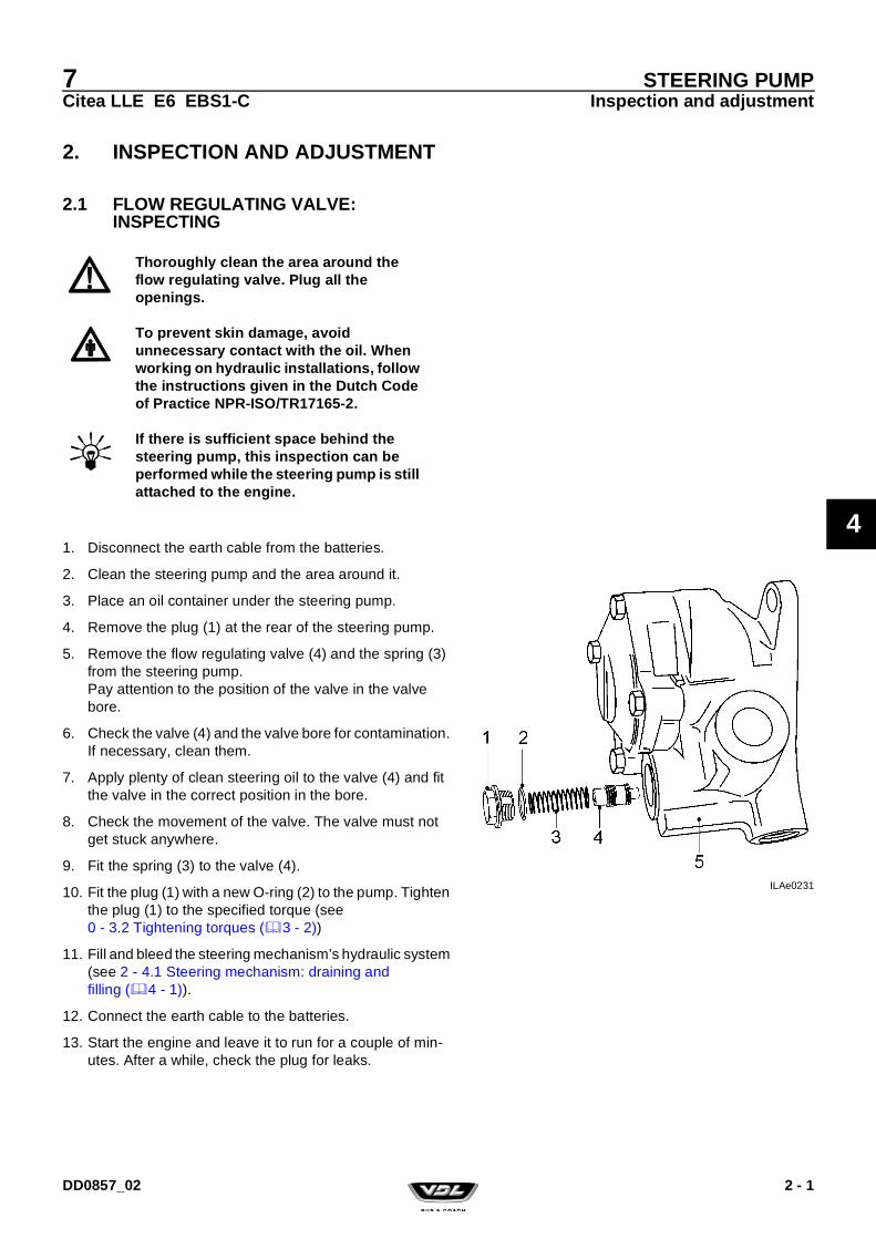
7Citea LLE E6 EBS1-C
STEERING PUMPInspection and adjustment
4
2. INSPECTION AND ADJUSTMENT
2.1 FLOW REGULATING VALVE: INSPECTING
1. Disconnect the earth cable from the batteries.
2. Clean the steering pump and the area around it.
3. Place an oil container under the steering pump.
4. Remove the plug (1) at the rear of the steering pump.
5. Remove the flow regulating valve (4) and the spring (3) from the steering pump.Pay attention to the position of the valve in the valve bore.
6. Check the valve (4) and the valve bore for contamination. If necessary, clean them.
7. Apply plenty of clean steering oil to the valve (4) and fit the valve in the correct position in the bore.
8. Check the movement of the valve. The valve must not get stuck anywhere.
9. Fit the spring (3) to the valve (4).
10. Fit the plug (1) with a new O-ring (2) to the pump. Tighten the plug (1) to the specified torque (see 0 - 3.2 Tightening torques (3 - 2))
11. Fill and bleed the steering mechanism’s hydraulic system (see 2 - 4.1 Steering mechanism: draining and filling (4 - 1)).
12. Connect the earth cable to the batteries.
13. Start the engine and leave it to run for a couple of min-utes. After a while, check the plug for leaks.
Thoroughly clean the area around the flow regulating valve. Plug all the openings.
To prevent skin damage, avoid unnecessary contact with the oil. When working on hydraulic installations, follow the instructions given in the Dutch Code of Practice NPR-ISO/TR17165-2.
If there is sufficient space behind the steering pump, this inspection can be performed while the steering pump is still attached to the engine.
ILAe0231
DD0857_02 2 - 1

7Citea LLE E6 EBS1-C
STEERING PUMPInspection and adjustment
4
2 - 2 DD0857_02

7Citea LLE E6 EBS1-C
STEERING PUMPRemoval and installation
4
3. REMOVAL AND INSTALLATION
3.1 GENERAL INFORMATION
To prevent skin damage, avoid unnecessary contact with the oil. When working on hydraulic installations, follow the instructions given in the Dutch Code of Practice NPR-ISO/TR17165-2.
Dirt in the system can cause serious damage to the hydraulic system’s components.
When replacing a worn hydraulic pump, it is recommended to completely drain the oil, to disassemble the hydraulic oil reservoir and clean it thoroughly, and to replace the filter. In extreme cases, it is possible that the hydraulic pump is worn to such an extent that pieces of metal from the hydraulic pump have entered the hydraulic motor.
Thoroughly clean the lines and hoses which are to be removed and their surrounding area. Plug all the connections, lines and hoses after disconnecting them.
Before starting the work, check whether all the components to be removed have cooled down.
3 - 1DD0857_02DD0857_02

7Citea LLE E6 EBS1-C
STEERING PUMPRemoval and installation
4
3.2 STEERING PUMP: REMOVING AND INSTALLING
The steering pump is part of the tandem pump. If necessary, the entire tandem pump must be replaced.For more information, see Group 2.
3 - 2 DD0857_02

7Citea LLE E6 EBS1-C
LINES AND RESERVOIR
5
LINES AND RESERVOIR
DD0857_02

7Citea LLE E6 EBS1-C
LINES AND RESERVOIR
5
DD0857_02

7Citea LLE E6 EBS1-C
LINES AND RESERVOIRGeneral information
5
1. GENERAL INFORMATION
1.1 LINES
Suction lineThe suction line (2) connects the reservoir (1) to the steering pump (3) and consists of a hydraulic hose which changes into a steel line.The hose is attached to the reservoir by a hose clamp and to the steel line by a union nut. The steel line is attached to the steering pump with a union nut.Since the steering pump does not prime itself, the reservoir must be fitted a certain height above the steering pump.The length of the suction line also affects the steering pump's operation.If the reservoir is moved and the suction line becomes longer because of this, then the reservoir must be moved higher.
Delivery lineThe delivery line (4) connects the steering pump (3) to the steering box (5) and consists of a hydraulic hose which changes into a steel line. A hydraulic hose is included in the steel line (near the steering box).The permissible pressure is marked on the hydraulic hoses.The line is connected to the steering pump and the steering box by a union nut.
Return lineThe return line (6) connects the steering box (5) to the reser-voir (1) and consists of a steel line and two hydraulic hoses.The line is connected to the steering box by a union nut and to the reservoir by a hydraulic hose and hose clips. A hydrau-lic hose is included in the steel line near the steering box. ILAe0266
1 - 1DD0857_02

7Citea LLE E6 EBS1-C
LINES AND RESERVOIRGeneral information
5
1.2 RESERVOIR
General information
The reservoir is made of plastic and consists of a black bot-tom section (1a) and a transparent top section (1b), which is intended for visually checking the oil level.The reservoir has a screw lid (3) and a level switch (2).The suction line is connected to the line connection (7).The return line is connected to the line connection (8).A filter element is fitted in the reservoir, which filters the return oil.The filter is not fitted into the suction line because, as a result of the filter resistance, the filter element and, therefore, the reservoir would have to be very large.The filter element (6) is secured into place by a plastic toggle (4).If the resistance in the filter is too large as a result of, for example, cold oil or a contaminated filter, then the filter ele-ment (6) will be partly pushed from its seat. This allows some of the oil to flow under the filter element (6) directly back into the reservoir.It is possible for the filter element (6) to move, since there is a spring (5) between the filter element (6) and the plastic tog-gle (4).
The fluid level switch (2) is closed if the steering oil level is below the minimum level.There is a maximum mark and a minimum mark on the dip-stick.There is a bleed hole in the dipstick’s rubber cap. This hole must always be open, otherwise the return pressure increases.
Prevent dirt from entering the reservoir or the lines when working on the steering mechanism. The steering oil is drawn in without being filtered and, therefore, small dirt particles can easily enter the steering mechanism.
ILAe0120
ILAe0234
1 - 2 DD0857_02

7Citea LLE E6 EBS1-C
LINES AND RESERVOIRInspection and adjustment
5
2. INSPECTION AND ADJUSTMENT
2.1 STEERING MECHANISM: CHECKING THE FLUID LEVEL
2.1.1 ELECTRONIC
The oil reservoir has a level switch which makes contact the moment the oil level becomes too low. A light will be lit to indi-cate that the oil must be topped up.The level switch is integrated in the dipstick.
Clean the top of the steering oil reservoir, so that no dirt can enter the reservoir if it must be topped up.
Always read the safety data sheet.To prevent skin damage, avoid unnecessary contact with the oil.
Only use hydraulic oil that meets VDL Bus & Coach specifications. For more information, see DW050335_xx on the VDL Bus & Coach Documentation Portal.
Only top up the hydraulic oil when the engine is switched OFF. Check the oil level when the engine is running.
ILAe0286
2 - 1DD0857_02

7Citea LLE E6 EBS1-C
LINES AND RESERVOIRInspection and adjustment
5
2.1.2 VISUAL/MANUAL
The reservoir consists of a black bottom section and a trans-parent top section, with MIN. and MAX. marks. The oil level can be observed through the transparent section.
Visually checking the steering oil level1. Place the vehicle on a flat, horizontal surface at the nor-
mal driving height.
2. Check the oil level in the reservoir.When the steering oil is cold, the level must be between the MIN and MAX. marks.
3. If necessary, top up the oil to the maximum mark via the filler cap (1).
ILAe0210
When the steering oil is at the operating temperature, the level may be above the maximum level.
2 - 2 DD0857_02

7Citea LLE E6 EBS1-C
LINES AND RESERVOIRInspection and adjustment
5
2.2 STEERING MECHANISM LINES/HOSES AND CONNECTIONS: CHECKING
Checking the hydraulic lines/hoses/connections
1. Condition of the lines and hoses– Check all the hydraulic lines and hoses for wear and
leaks.In particular, porous suction hoses with a vacuum pres-sure will cause a problem (air in the system).
– If in doubt, always replace the lines and/or hoses.
2. Line and hose connections– Check each line and hose connection for leaks.
3. Path of the hose– The hoses must not be twisted. To make it easier to
check this, a mark may be drawn on the hoses (some-times text).
– The lines and hoses must lay freely (think of the possi-bility of them rubbing through and noises that can be heard in the vehicle).
– The hoses must not make any sharp turns, especially not the flexible supply line and the return line.
– The hoses must not be pinched closed by other com-ponents.
4. Line/hose attachment– Check the attachment of the clamping blocks/lines.– Check whether all the clamping blocks/rubbers are
present.
Checking the steering box attachment1. Make sure the weight of the vehicle rests on the front
wheels.
2. Idle the engine.
3. Jerk the steering wheel a couple of times and visually check the attachment of the steering box and the steer-ing bracket. Pay attention to any marks on the attach-ment (corrosion, paint damage).
CommentIf there is any doubt regarding the attachment, the bolts may only be tightened according to the instructions given in the Workshop Instructions.
To prevent skin damage, avoid unnecessary contact with the oil.When working on hydraulic installations, follow the instructions given in the Dutch Code of Practice NPR-ISO/TR 17165-2.
2 - 3DD0857_02

7Citea LLE E6 EBS1-C
LINES AND RESERVOIRInspection and adjustment
5
2 - 4 DD0857_02

7Citea LLE E6 EBS1-C
LINES AND RESERVOIRRemoval and installation
5
3. REMOVAL AND INSTALLATION
3.1 STEERING MECHANISM FILTER: REMOVING AND INSTALLING
The oil should be changed, the filter element should be replaced and the reservoir should be cleaned, if there is seri-ous damage to the steering pump or the steering box.
Removing the filter element1. Clean the cover (3), the reservoir and the surrounding
area so that no dirt can enter the steering oil reservoir.
2. Remove the cover (3).
3. Unscrew the filter holder (5) a quarter of a turn. Slowly remove the filter holder together with the filter element (6) from the steering oil reservoir so that no dirt from the filter element falls into the reservoir.
4. Remove the filter element (6) from the filter holder (5).
5. Replace the filter element.
Installing1. Fit the new filter element (6) onto the filter holder (5).
2. Fit the filter holder and the new filter element into the res-ervoir (1). Make sure the filter holder falls into the lock.
To prevent skin damage, avoid unnecessary contact with the oil.
Dirt in the system can cause a great deal of damage to various components of the hydraulic system, such as the steering pump. Therefore, thoroughly clean the lines and hoses which are to be removed and their surrounding area. Plug all the connections, lines and hoses after disconnecting them.
When working on hydraulic installations, follow the instructions given in the Dutch Code of Practice NPR-ISO/TR17165-2.
ILAe0123
3 - 1DD0857_02

7Citea LLE E6 EBS1-C
LINES AND RESERVOIRRemoval and installation
5
3.2 RESERVOIR: REMOVING AND INSTALLING
Removing the reservoir1. Clean the reservoir and its surrounding area.
2. Drain the steering oil (see 2 - 4.1 Steering mechanism: draining and filling (4 - 1)).
3. Place a container under the reservoir.
4. Remove the cover from the reservoir.
5. Remove the filter element from the reservoir.
6. Remove all the hoses connected to the reservoir.Plug the hose/line openings.
7. Remove the bracket and remove the reservoir.
Installing the reservoir1. Thoroughly clean the inside of the reservoir.
2. Fit a new filter element into the reservoir.
3. Install the reservoir.
4. Check the condition of the hoses and connect them to the reservoir.
5. Secure the hoses using new hose clips. Tighten the hose clips.
6. Fill and bleed the system (see 2 - 4.1 Steering mecha-nism: draining and filling (4 - 1)).
7. Check the hose connections for leaks.
3 - 2 DD0857_02

7Citea LLE E6 EBS1-C
LINES AND RESERVOIRRemoval and installation
5
3.3 LINES: REMOVING AND INSTALLING
Removing lines1. Clean the line connection and its surrounding area.
2. Place a container under the line connection.
3. Remove the line and plug the openings.
Installing lines1. Only fit original lines supplied by VDL Bus & Coach.
2. Points of attention when connecting lines:• Replace the O-ring.• Prevent the line from rotating when tightening the con-
nection.To make it easier to check this, a mark may be drawn on the hose (sometimes in the form of writing).
• The lines must not touch anything (think of the possibil-ity of them rubbing through).
• The lines must not make any sharp turns, especially not the flexible suction line and the return line.
• The line must not be clamped off by other components.
3. If the hose is fixed into place using a hose clip, replace the hose clip.Tighten the hose clip.If a union nut is used, check the conical sections for faults.
3 - 3DD0857_02

7Citea LLE E6 EBS1-C
LINES AND RESERVOIRRemoval and installation
5
4. Fit the line rubbers as follows:• Apply a locking compound to the threaded stud (8) (see
0 - 4.1.5 Control line rubbers (4 - 2)).• Screw the threaded end (8) approx. 6 mm into the
vibration damper (2) by hand. Allow the locking com-pound to harden for at least 45 minutes.
• Fit the vibration dampers (2, 8 and 9) in the chassis with the nut (1).
• Apply Vaseline to the parts of the line clamp (4).• Fit the lines, the line clamps (4) and the plates (3 and
5).• Apply a locking compound to the nut/bolt (6) (see
0 - 4.1.5 Control line rubbers (4 - 2)).Tighten the nut/bolt by hand.
• Slide the lines into the rubbers so that the lines are at least 10 mm from other components, 5 mm from each other and free of tension.
• Tighten the nut/bolt (6).
5. Fill and bleed the system.
6. Check the line connections for leaks.ILAe0139
A. Situation with vibration damper.B. Situation without vibration damper.C. Situation for clamping block with vibration
damper.
ILAe0067
Do not tighten the nut/bolt (6) too tight. The plates and the rubbers must not be rotated. The rubbers must not protrude from the plates. The use of a pneumatic spanner is not permitted.
3 - 4 DD0857_02

7Citea LLE E6 EBS1-C
BEVEL BOX
6
BEVEL BOX
DD0857_02

7Citea LLE E6 EBS1-C
BEVEL BOX
6
DD0857_02

7Citea LLE E6 EBS1-C
BEVEL BOXGeneral information
6
1. GENERAL INFORMATION
1.1 GENERAL VIEW OF THE BEVEL BOX
1.2 OPERATION
The bevel box is attached to the chassis by two brackets.The bevel box forms the connection between the steering column and the horizontal steering box.The steering column is attached to the bevel box's input shaft (1). The output shaft (11) is connected to the steering box’s input shaft by a steering shaft.
The bevel box consists of two conical gear wheels which form a single unit with the input shaft (1) and the output shaft (11). The conical gear wheels engage each other free of tension.The input shaft (1) is born by a ball bearing (4) at the top and by a bearing bush (5) at the bottom. Everything is sealed in the housing by a circlip (3). The input shaft and the output shaft have an oil seal (2 and 10) to prevent the penetration of dirt.
The output shaft (11) is born by a bearing bush (7) on the inside and by a bearing (8) on the outside. Everything is sealed in the housing by a circlip (9).
ILAe0127
1 Input shaft2 Oil seal3 Circlip4 Ball bearing5 Bearing bush6 Housing7 Bearing bush8 Ball bearing9 Circlip10 Oil seal11 Output shaft
1 - 1DD0857_02

7Citea LLE E6 EBS1-C
BEVEL BOXGeneral information
6
1 - 2 DD0857_02

7Citea LLE E6 EBS1-C
BEVEL BOXRemoval and installation
6
2. REMOVAL AND INSTALLATION
2.1 BEVEL BOX: REMOVING AND INSTALLING
Removing the bevel box1. Put the steering mechanism in the middle position. This
can be checked using the marks on the steering box.
2. Place the steering column into the lowest telescopic posi-tion and then tilt it into the lowest position.
3. Remove the steering rod's (10) universal joint on the bevel box (9).
4. Remove the attachment nuts (2) and bolts (1) from the left-hand and right-hand filler plates (3).
5. Remove the attachment nuts (8) and bolts (7) from the bevel box (9).Pull the bevel box backwards as far as possible and then downwards. Make sure the output shaft does not get damaged.Remove the filler plates (3).
6. Remove the attachment nuts (5) and bolts (4) from the universal joint (6).
7. Remove the bevel box (9) from the vehicle.
Installing the bevel box1. Check whether the bevel box is free of play.
2. Place the steering wheel in the straight ahead position and rotate the bevel box so that the marks on the output shaft face upwards.
3. Fit the steering column's universal joint (6) to the bevel box's (9) input shaft.
4. Fit the new attachment bolt (4) with a new nyloc nut (5). Tighten the bolt to the specified torque (see 0 - 5.3 Tightening torques (5 - 3)).
5. Fit the bevel box (9) with the filler plates (3). Tighten the nuts (8) and bolts (7).
6. Fit the attachment nuts (2) and bolts (1) for the left-hand and right-hand filler plates (3).
7. Check whether the steering box and the bevel box are still in the middle position.
8. Fit the steering rod's (10) universal joint on to the bevel box (9).The groove in the universal joint must be perpendicular to the mark on the output shaft.
9. Fit a new, original nut and bolt in the universal joint.
ILAe0337
ILAe0168
Check whether the steering shaft has been correctly fitted to the output shaft, so that the bolt can be fitted in the recess.
2 - 1DD0857_02

7Citea LLE E6 EBS1-C
BEVEL BOXRemoval and installation
6
Tighten the bolt to the specified torque (see 0 - 2.2 Tightening torques (2 - 3)).
10. Check whether the steering box and the bevel box are still in the middle position.
ILAe0337
2 - 2 DD0857_02

7Citea LLE E6 EBS1-C
STEERING COLUMN
7
STEERING COLUMN
DD0857_02

7Citea LLE E6 EBS1-C
STEERING COLUMN
7
DD0857_02

7Citea LLE E6 EBS1-C
STEERING COLUMNGeneral information
7
1. GENERAL INFORMATION
1.1 GENERAL VIEW OF THE STEERING COLUMN
ILAe0385
1. Steering wheel 11. Bevel gear box2. Nyloc nut 12. Clamping block3. Regulating ring (only in the case of a steering lock) 13. Steering column sleeve attachment brackets4 Steering column cover 14. Steering column switch5. Steering column cover 15. Wiring harness6. Steering column, top part 16. Vehicle floor7. Bracket 17. Steering column lock8. Steering shaft 18. Sealing plate9. Right-hand filler plate 19. Steering angle sensor (ESC)10. Left-hand filler plate
1 - 1DD0857_02
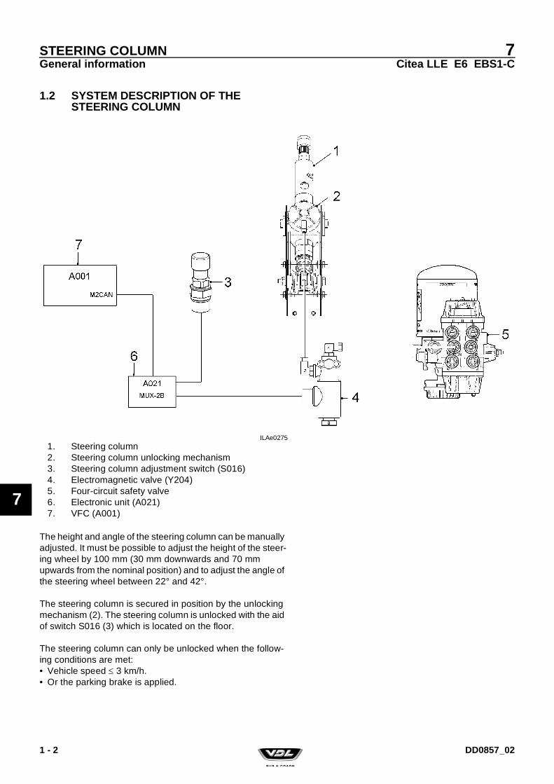
7Citea LLE E6 EBS1-C
STEERING COLUMNGeneral information
7
1.2 SYSTEM DESCRIPTION OF THE STEERING COLUMN
The height and angle of the steering column can be manually adjusted. It must be possible to adjust the height of the steer-ing wheel by 100 mm (30 mm downwards and 70 mm upwards from the nominal position) and to adjust the angle of the steering wheel between 22° and 42°.
The steering column is secured in position by the unlocking mechanism (2). The steering column is unlocked with the aid of switch S016 (3) which is located on the floor.
The steering column can only be unlocked when the follow-ing conditions are met:• Vehicle speed 3 km/h.• Or the parking brake is applied.
ILAe0275
1. Steering column2. Steering column unlocking mechanism3. Steering column adjustment switch (S016)4. Electromagnetic valve (Y204)5. Four-circuit safety valve6. Electronic unit (A021)7. VFC (A001)
1 - 2 DD0857_02

7Citea LLE E6 EBS1-C
STEERING COLUMNGeneral information
7
If the condition given above is met, the solenoid Y204 (4) is activated by the electronic unit A021 (6), so that inlet 1 is con-nected to outlet 2.
The steering column can be adjusted as long as the switch S016 (3) is pressed.
ILAe0276
1 - 3DD0857_02

7Citea LLE E6 EBS1-C
STEERING COLUMNGeneral information
7
1.3 STEERING ANGLE SENSOR COMPONENT DESCRIPTION
FunctionThe steering angle sensor measures the steering wheel’s angular rotation and transmits this to the ESC system.The sensor transmits the absolute steering angle via a CAN data link. The steering angle sensor covers the steering wheel’s full rotational range of 1,440 degrees (4 revolutions).
OperationThe steering angle sensor is fitted on the steering column.
The steering angle is measured via three gear wheels. On two of these gear wheels, there are two magnets that are monitored by two different AMR elements in the gaps.The resistance varies depending on the direction of the magnetic field.
The gear wheels on which the magnets are fitted have a different number of teeth and rotate in opposite directions. This makes it possible to accurately determine, at any time, the angle of the steering wheel and the speed at which the steering wheel is turned. The information is sent to the ESC control unit via the CAN-bus. Both gear wheels (B) are driven by the gear wheel (A), which is connected to the steering shaft.
The angle of the steering wheel is measured by the steering angle sensor. A prediction is made as to whether there is a risk of the vehicle tipping over based on the steering angle sensor’s information; for the transverse stability, it is checked whether the vehicle’s reaction is in accordance with the driver’s demands. After the contact has been turned on, the steering angle sensor’s middle position and the relationship between the steering wheel rotation and the wheel turning angle are automatically checked whilst the vehicle is being driven.
ILAh1128
ILAh1129
1 - 4 DD0857_02

7Citea LLE E6 EBS1-C
STEERING COLUMNGeneral information
7
Middle position of the steering angle sensorThis check is made by checking the steering angle sensor’s middle position when in the straight ahead position (the straight ahead information comes from the transverse acceleration and yaw angle speed sensor) and, if necessary, adjusting it via the software.If the deviation from the middle position is too great, an ESC error message is activated on the instrument panel.
Relationship between the steering wheel’s angle of rota-tion and the wheel turning angleThe relationship between the steering wheel's angle of rotation and the wheel turning angle is checked by comparing the steering wheel angle, vehicle speed, measured yaw angle speed and wheel turning angle to each other. The various units are measured at different steering wheel angles and then saved as experience values in the EBS unit. These experience values are compared to the parameters saved in the EBS unit. For example, if after a repair to the steering mechanism, an incorrect or different setting is entered, the units may differ from the experience values or the parameters previously saved in the EBS unit. If the deviation is too great, an ESC error message is activated on the instrument panel.
1 - 5DD0857_02

7Citea LLE E6 EBS1-C
STEERING COLUMNGeneral information
7
1 - 6 DD0857_02

7Citea LLE E6 EBS1-C
STEERING COLUMNInspection and adjustment
7
2. INSPECTION AND ADJUSTMENT
2.1 STEERING COLUMN: INSPECTING THE ADJUSTMENT
1. Check whether the height and angle of the steering col-umn can be adjusted after the unlocking valve has been activated.
2. Check whether the unlocking mechanism is locked cor-rectly after the unlocking valve has been released.
3. Check whether the unlocking valve is bled after being released.If this is not the case, check whether any air lines are pinched. If this is not the case, then replace this valve.
4. Check whether the electromagnetic valve is bled:• After the parking brake has been released.
Or• The vehicle speed is 3 km/h.
If this is not the case, check the input signal of A021 on the solenoid. If there is a signal, check whether any air lines are pinched. If necessary, replace the solenoid.
ILAe0275
1. Steering column2. Steering column unlocking mechanism3. Steering column adjustment switch (S016)4. Electromagnetic valve5. Four-circuit safety valve6. Electronic unit (A021)7. VFC (A001)
Conditions for unlocking the steering column:A vehicle speed of 3 km/h or the parking brake is applied.
2 - 1DD0857_02

7Citea LLE E6 EBS1-C
STEERING COLUMNInspection and adjustment
7
2 - 2 DD0857_02

7Citea LLE E6 EBS1-C
STEERING COLUMNRemoval and installation
7
3. REMOVAL AND INSTALLATION
3.1 BATTERY TERMINAL CLAMPS: REMOVING AND INSTALLING
See 0 - 1.1 Battery terminal clamp tightening torques (1 - 1) for the battery terminal clamp tightening torques.
In order to prevent the DTCO-1381 tachograph from saving an error code, the driver's card must be replaced by the workshop card before the battery terminal clamp and the negative pole are disconnected.
Do not place any tools or other materials on or near the batteries. This could short-circuit the battery or may even cause the battery to explode.
Always disconnect the connection between the battery terminal clamp and the negative pole when working on the vehicle.
To prevent damage to electronic components, never disconnect the battery terminal clamps when the engine is running.
Turn off the contact switch before disconnecting the connection between the battery terminal clamp and the negative pole.
Wait at least 80 seconds after turning off the contact switch before disconnecting the connection between the battery terminal clamp and the negative pole.The AdBlue lines may become blocked if the connection is disconnected too quickly.
Avoid sparks and naked flames near the batteries.
3 - 1DD0857_02

7Citea LLE E6 EBS1-C
STEERING COLUMNRemoval and installation
7
3.2 STEERING COLUMN COVERS: REMOVING AND INSTALLING
Removing the steering column covers1. Use the steering column adjustment switch to place the
steering column in the highest position.
2. Remove the Torx screws, paying attention to the snap nuts at the rear of the covers.
3. Remove the covers.
Installing the steering column covers1. Check the path of the steering column switch wiring har-
ness.The wiring harness must always be fitted to the right of the steering column with the aid of the assembly clip.
2. Fit the snap nuts, paying attention to the position of the snap nuts.
3. Fit the covers.
ILAe0172
1. Torx Allen screw2. Snap nut3. Assembly bracket4. Cover5. Cover6. Wiring harness7. Assembly bracket
3 - 2 DD0857_02

7Citea LLE E6 EBS1-C
STEERING COLUMNRemoval and installation
7
3.3 STEERING WHEEL: REMOVING AND INSTALLING
Removing the steering wheel1. Use the marks on the steering box to put the steering
mechanism in the middle position.
2. Remove the cover plate (1) from the steering wheel (2).
3. Remove the steering wheel lock nut (3).
4. Attach the steering wheel extractor (A) (VDL Bus & Coach no. 41453199) to the steering wheel using the outer bolts. Tighten the steering wheel extractor’s central bolt until the steering wheel comes loose.
ILAe0337
ILAe0338
3 - 3DD0857_02

7Citea LLE E6 EBS1-C
STEERING COLUMNRemoval and installation
7
Installing the steering wheel1. Use the marks on the steering box to check whether the
steering mechanism is in the middle position.
2. Fit the steering wheel (2) to the steering shaft (4) so that the marks on the steering wheel and the steering shaft (see arrow B) are aligned.
3. Fit the attachment nut (3). Tighten the nut to the specified torque (see 0 - 5.3 Tightening torques (5 - 3)).
4. Fit the cover plate (1).
5. If the steering wheel is not in the middle position, then the following must be carried out:• Remove the steering shaft from the steering column’s
output shaft.• Check whether the steering box is in the middle posi-
tion.• Turn the steering wheel so that the marks on the steer-
ing wheel (B) and the steering column's output shaft are aligned.
• Next, fit the steering shaft to the steering column’s out-put shaft without changing the settings.
ILAe0337
3 - 4 DD0857_02

7Citea LLE E6 EBS1-C
STEERING COLUMNRemoval and installation
7
3.4 STEERING COLUMN SWITCHES: REMOVING AND INSTALLING
3.4.1 LEFT-HAND STEERING COLUMN SWITCH
Removing1. Remove the steering column covers (see
7 - 3.2 Steering column covers: removing and installing (3 - 2)).
2. Disconnect the batteries' earth terminal clamp (see 7 - 3.1 Battery terminal clamps: removing and installing (3 - 1)).
3. Disconnect the connector from the steering column switch and remove the steering column switch.
Installing the steering column switch1. Use the marks on the steering column to place the steer-
ing mechanism in the middle position.The stop cam (C) is located on the left-hand side of the steering column.
2. Fit the steering column switch and connect the connec-tor.
3. Check whether the indicator turns off at approximately the same angle (< 135º) on both sides.
4. Fit the steering column covers (see 7 - 3.2 Steering col-umn covers: removing and installing (3 - 2)).
5. Connect the batteries’ earth terminal clamp (see 7 - 3.1 Battery terminal clamps: removing and installing (3 - 1)).
ILAe0078
C. Indicator stop cam
ILAe0337
To turn the indicator off at the right moment, the steering wheel must be fitted in the correct position with regard to the steering column shaft with the aid of the marks.
Make sure the wiring harness is long enough for the steering column’s entire adjustment range.
3 - 5DD0857_02

7Citea LLE E6 EBS1-C
STEERING COLUMNRemoval and installation
7
3.4.2 RIGHT-HAND STEERING COLUMN SWITCH
Removing1. Disconnect the batteries' earth terminal clamp (see
7 - 3.1 Battery terminal clamps: removing and installing (3 - 1)).
2. Remove the steering column covers (see 7 - 3.2 Steering column covers: removing and installing (3 - 2)).
3. Disconnect the connector from the steering column switch and remove the steering column switch.
Installing the steering column switch1. Use the marks on the steering column to place the steer-
ing mechanism in the middle position.The stop cam (C) is located on the left-hand side of the steering column.
2. Fit the steering column switch and connect the connec-tor.
3. Check whether the indicator turns off at approximately the same angle (< 135º) on both sides.
4. Fit the steering column covers (see 7 - 3.2 Steering col-umn covers: removing and installing (3 - 2)).
5. Connect the batteries’ earth terminal clamp (see 7 - 3.1 Battery terminal clamps: removing and installing (3 - 1)).
ILAe0237
C. Indicator stop cam
ILAe0337
To turn the indicator off at the right moment, the steering wheel must be fitted in the correct position with regard to the steering column shaft with the aid of the marks.
Make sure the wiring harness is long enough for the steering column’s entire adjustment range.
3 - 6 DD0857_02

7Citea LLE E6 EBS1-C
STEERING COLUMNRemoval and installation
7
3.5 STEERING COLUMN: REMOVING AND INSTALLING THE TOP SECTION
Removing the top section of the steering column1. Put the steering mechanism in the middle position.
This can be checked using the marks on the steering box.
2. Remove the steering wheel (see 7 - 3.3 Steering wheel: removing and installing (3 - 3)).
3. Remove the steering column covers (2) (see 7 - 3.2 Steering column covers: removing and installing (3 - 2)).
4. Remove the steering column switch (3) (see 7 - 3.4 Steering column switches: removing and installing (3 - 5)).
5. Remove the steering angle sensor (see 7 - 3.7 Steering angle sensor: removing and installing (3 - 11)).
6. Remove the attachment brackets (4) for the steering col-umn covers.
ILAe0037
ILAe0175
3 - 7DD0857_02

7Citea LLE E6 EBS1-C
STEERING COLUMNRemoval and installation
7
7. Disconnect the air hose (1) for the pneumatic steering column adjustment mechanism from the electromagnetic valve and plug the line.
8. Remove the top universal joint’s bolt (5).
9. Remove the nuts (8) and bolts (7) and remove the top section (9) of the steering column brackets (10).
Installing the top section of the steering column1. Use the marks to check whether the steering wheel and
the bevel box are in the middle position.
2. Fit the steering shaft's (6) universal joint to the top sec-tion of the steering column (9).
3. Fit a new, original bolt (5) in the universal joint. Tighten the bolt to the specified torque (see 0 - 5.3 Tightening torques (5 - 3)).
4. Attach the top section of the steering column (9) to the steering column bracket (10) using new nuts (8) and bolts (7).
ILAe0173
ILAe0261
ILAe0261
Check whether the universal joint has been correctly fitted to the top section of the steering column, so that the bolt can be fitted in the recess.
3 - 8 DD0857_02

7Citea LLE E6 EBS1-C
STEERING COLUMNRemoval and installation
7
5. Connect the pneumatic steering column adjustment mechanism’s air hose (1) to the electromagnetic valve.
6. Fit the attachment brackets(4) for the steering column covers (2).
7. Fit the steering column switch (see 7 - 3.4 Steering col-umn switches: removing and installing (3 - 5)).
8. Fit the steering angle sensor (see 7 - 3.7 Steering angle sensor: removing and installing (3 - 11)).
9. Turn the steering column as far as possible to both sides and check whether the wiring harness/air line get stuck or rub against any components.
10. Fit the steering column covers (see 7 - 3.2 Steering col-umn covers: removing and installing (3 - 2)).
11. Fit the steering wheel (see 7 - 3.3 Steering wheel: removing and installing (3 - 3)).
ILAe0173
ILAe0175
3 - 9DD0857_02

7Citea LLE E6 EBS1-C
STEERING COLUMNRemoval and installation
7
3.6 STEERING SHAFT: REMOVING AND INSTALLING
Remove the steering shaft1. Remove the bevel box (see 6 - 1.1 General view of the
bevel box (1 - 1)).
2. Mark the position of the bottom universal joint (1) with regard to the steering shaft.Remove the bottom universal joint.
3. Remove the cable tie (4) and the protective cap (3).
4. Remove the attachment bolts of the cover (5) and the covering plate (6).
5. Remove the top section of the steering column (see 7 - 3.5 Steering column: removing and installing the top section (3 - 7)).
6. Remove the steering shaft (2) from the vehicle.
Installing the steering shaft
1. Insert the steering shaft from the top through the cover (5), the sealing plate (6) and the steering column bracket (7).
2. Fit the bottom universal joint (1) in the same position back on the steering shaft (2).
3. Fit the protective cap (3) and the cable tie (4).
4. Tighten all the nuts/bolts to the specified torque (see 0 - 5.3 Tightening torques (5 - 3)).
5. Fit the bevel box (see 6 - 1.1 General view of the bevel box (1 - 1)).
6. Fit the top section of the steering column (see 7 - 3.5 Steering column: removing and installing the top section (3 - 7)).
ILAe0262
If a new steering shaft is fitted, mark the bottom universal joint and disassemble this from the steering column.
3 - 10 DD0857_02

7Citea LLE E6 EBS1-C
STEERING COLUMNRemoval and installation
7
3.7 STEERING ANGLE SENSOR: REMOVING AND INSTALLING
Removing the steering angle sensor
1. Put the steering mechanism in the middle position. This can be checked using the marks on the steering box.
2. Disconnect the batteries' earth terminal clamp (see 7 - 3.1 Battery terminal clamps: removing and installing (3 - 1)).
3. Remove the steering wheel (see 7 - 3.3 Steering wheel: removing and installing (3 - 3)).
4. Remove the steering column covers (see 7 - 3.2 Steering column covers: removing and installing (3 - 2)).
5. Disconnect the connector at the bottom (3) of the steer-ing angle sensor (1).
6. Remove the three screws and washers (2).
7. Carefully slide the steering angle sensor (1) upwards.
8. Remove the steering angle sensor from the steering shaft.
Be careful when removing the steering angle sensor. It is very fragile.
ILAe0247
3 - 11DD0857_02

7Citea LLE E6 EBS1-C
STEERING COLUMNRemoval and installation
7
Installing the steering angle sensor
1. Apply a small amount of grease to the groove in the steering column.(Klüber ISOFLEX TOPAS L 32 N (JED-785))
2. Hold the steering angle sensor in the assembly position above the steering shaft.
3. Slide the steering angle sensor’s cam carefully into the groove in the steering shaft.
4. Slide the steering angle sensor carefully downwards as far as the three assembly cams.
5. Check whether the steering angle sensor touches all three contact surfaces.
6. Fit the three washers and screws (2) with Loctite 243.
7. Check whether the steering shaft is exactly in the middle of the steering angle sensor's hole.
8. Connect the steering angle sensor’s connector.
9. Fit the steering column covers (see 7 - 3.2 Steering col-umn covers: removing and installing (3 - 2)).
10. Fit the steering wheel (see 7 - 3.3 Steering wheel: removing and installing (3 - 3)).
11. Connect the batteries’ earth terminal clamp (see 7 - 3.1 Battery terminal clamps: removing and installing (3 - 1)).
12. Calibrate the steering angle sensor (see 7 - 3.8 Steering angle sensor: calibrating (3 - 13)).
Be careful when installing the steering angle sensor. It is very fragile.
If another type of grease is used, then it must satisfy the fundamental properties of the specified grease.
ILAe0126
When turning the steering shaft, there must be no play between the steering shaft groove and the sensor’s cam.
3 - 12 DD0857_02

7Citea LLE E6 EBS1-C
STEERING COLUMNRemoval and installation
7
3.8 STEERING ANGLE SENSOR: CALIBRATING
3.8.1 Calibration: using the VDL Bus & Coach diagnosis tool
Step 1: Starting the VDL Bus & Coach diagnosis program• Turn on the diagnosis tool.• Start the VDL Bus & Coach diagnosis program.• Select "Diagnosis".• Enter the vehicle manufacturer, the vehicle model and the
type of engine.• Go to "Self diagnosis", "Network system" and select
"Steering angle sensor" (see ILAi0839).• Connect the diagnosis tool to the vehicle.• Turn on the contact switch.• Select ‘’Confirm’’.
Step 2: Calibrating the steering angle sensor• Select "Settings".• Select "Calibration steering angle sensor".• Select ‘’Adjust’’.• Enter the PIN code and select "Confirm" (see ILAi0840).
• Place the front axle's wheels in the straight-ahead position and select "Confirm" (see ILAi0841).
ILAi0839
ILAi0840
Incorrectly calibrating the steering angle sensor may result in damage to the vehicle!
ILAi0841
3 - 13DD0857_02

7Citea LLE E6 EBS1-C
STEERING COLUMNRemoval and installation
7
• Enter the current date (dd/mm/yyyy) and select "Confirm" (see ILAi0842).
• The steering angle sensor has now been calibrated.• Select ‘’Confirm’’.
Step 3: Closing the diagnosis program• Select ‘’Faults’’ to check the vehicle's fault memory.• Delete any error codes that may be present. • Click the following icon to close the diagnosis program:
• Disconnect the diagnosis tool from the vehicle.
ILAi0842
3 - 14 DD0857_02

7Citea LLE E6 EBS1-C
FRONT AXLE
8
FRONT AXLE
DD0857_02

7Citea LLE E6 EBS1-C
FRONT AXLE
8
DD0857_02

7Citea LLE E6 EBS1-C
FRONT AXLEGeneral information
8
1. GENERAL INFORMATION
1.1 GENERAL VIEW OF THE FRONT AXLE
ILAd0468
1. NDS56LF axle beam2. Wheel hub3. Swivel axle4. Track rod5. Brake caliper6. Brake cylinder
1 - 1DD0857_02

7Citea LLE E6 EBS1-C
FRONT AXLEGeneral information
8
1.2 GENERAL VIEW OF THE WHEEL HUB AND SWIVEL AXLE
ILAd0536
1 - 2 DD0857_02

7Citea LLE E6 EBS1-C
FRONT AXLEGeneral information
8
1. Wheel nut cap 23. O-ring2. Wheel nut 24. Bearing bush3. Hub flange 25. Spacer washer4. Wheel bolt 26. Cover5. Hub nut 27. Grease nipple6. Locking plate 28. Clamping bush7. Brake disc 29. ABS sensor8. Wheel bearing unit 30. Steering arm9. Brake caliper/brake caliper bracket 31. Bolt10. Swivel axle 32. Nut11. Brake cylinder 33. Spring washer12. Nut 34. Spacer washer13. Axle stub 35. Thrust bearing14. Bolt 36. Key-pin15. Bolt and lock nut (wheel turning angle
adjustment)37. Axle beam
16. Wheel hub bolt 38. Track rod arm17. Grease nipple 39. Bolt18. Cover 40. Castellated nut19. Spacer washer 41. Split pin20. Bearing bush 42. Track rod ball joint21. O-ring 43. Retaining clip22. Kingpin
1 - 3DD0857_02

7Citea LLE E6 EBS1-C
FRONT AXLEGeneral information
8
1.3 DESCRIPTION OF THE WHEEL HUB
Wheel hub unitThe wheel bearing unit (5) and the hub flange (4) together form the wheel hub. The thrust washer (2), which has two straight surfaces on the inside, prevents the hub nut (1) from coming loose in the event of bearing problems.The hub nut must be manually locked. The wheel bearing unit (5) consists of two conical roller bear-ings (9) which are integrated in the bearing unit. The bear-ings of the bearing unit are grease-lubricated and maintenance-free. The correct wheel bearing tension is achieved by tightening the hub nut (1) to the specified torque.It is not possible to replace individual bearings. The bearing unit (5) must always be replaced as a complete unit.
The hub flange (4) and the brake disc (6) are fitted against the bearing unit (5) using bolts (3).The brake calliper bracket (7) is bolted against the swivel axle.
ILAd0244
1 - 4 DD0857_02

7Citea LLE E6 EBS1-C
FRONT AXLEGeneral information
8
1.4 DESCRIPTION OF THE WHEEL SETTINGS
Axle tiltThe axle tilt (Z) is the angle that the axle beam makes with the road. The axle tilt is important for the vehicle to remain on the chosen path.Too little axle tilt can lead to the vehicle “searching” for the right line, whilst too much axle tilt can result in heavy steering of the vehicle.Deviations in the axle tilt will not result in tyre wear.The axle tilt is constructively determined in relation to the chassis, where it is assumed that the chassis is parallel to the road surface.The axle tilt can be checked very easily and does not require any complicated equipment.
ILAd0245
1 - 5DD0857_02

7Citea LLE E6 EBS1-C
FRONT AXLEGeneral information
8
Camber and kingpin inclinationThe camber (X) and the kingpin inclination (Y) are deter-mined by the construction of the swivel axle and the axle beam and cannot be adjusted.Deviations in these wheel settings can only be the result of a collision and/or a bent front axle due to overloading. If a vehi-cle has a deviation in one of these settings, then the tyre load will not be evenly distributed over the road surface. This will cause the tyres to have an uneven wear pattern.The inspection must be carried out on each wheel individu-ally.
ToeThe toe is understood to be the difference between distances A and B.If distance A is smaller than distance B, then there is toe-in.If distance A is greater than distance B, then there is toe-out.
The manufacturer determines whether a vehicle must have toe-in or toe-out.
Toe-in or toe-out is necessary to ensure that the wheels roll correctly when driving in a straight line.
Deviations in the toe-in or toe-out cause the tyres to rub over the road surface. This will cause the tyres to have an uneven wear pattern.
ILAe0017
X CamberY Kingpin inclinationR Camber offset
ILAe0019
ILAe0080
1 - 6 DD0857_02
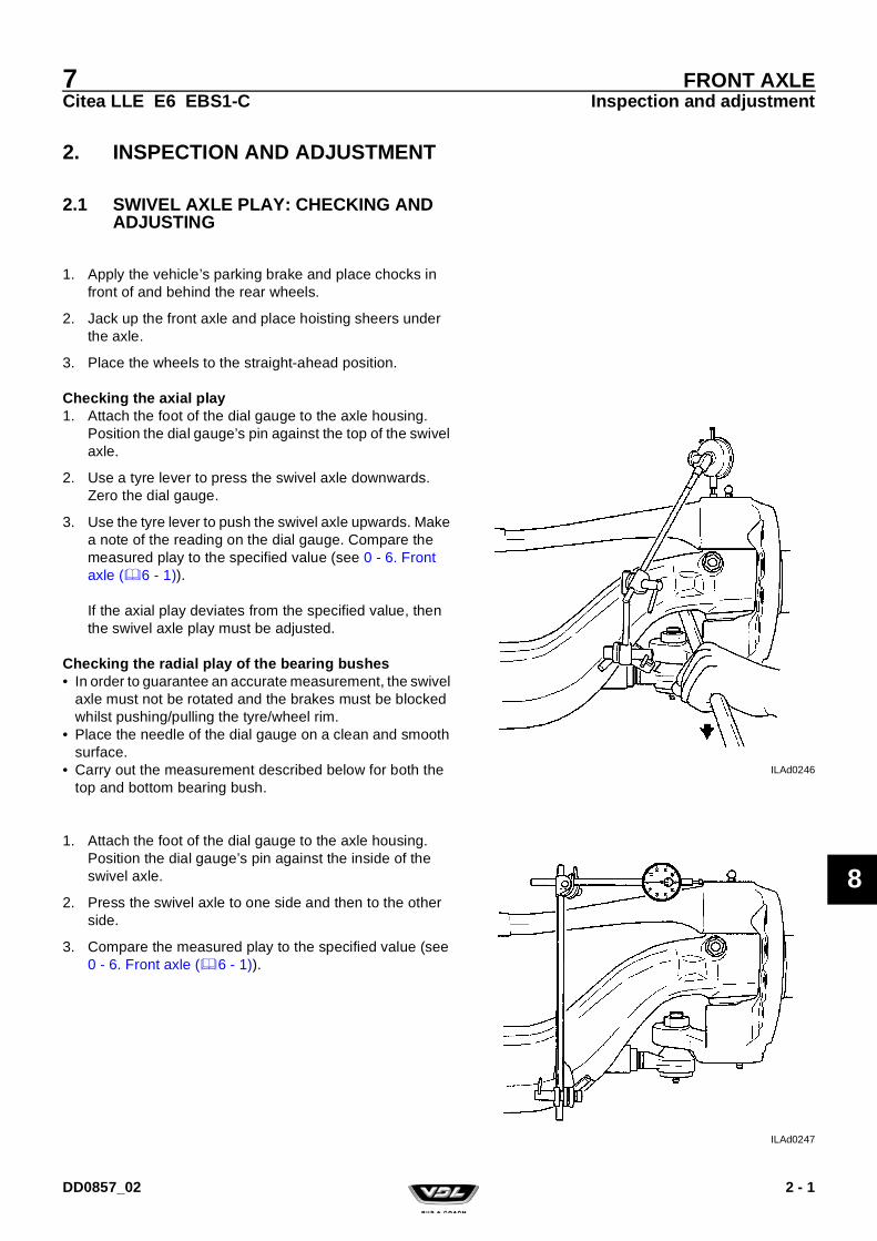
7Citea LLE E6 EBS1-C
FRONT AXLEInspection and adjustment
8
2. INSPECTION AND ADJUSTMENT
2.1 SWIVEL AXLE PLAY: CHECKING AND ADJUSTING
1. Apply the vehicle’s parking brake and place chocks in front of and behind the rear wheels.
2. Jack up the front axle and place hoisting sheers under the axle.
3. Place the wheels to the straight-ahead position.
Checking the axial play1. Attach the foot of the dial gauge to the axle housing.
Position the dial gauge’s pin against the top of the swivel axle.
2. Use a tyre lever to press the swivel axle downwards. Zero the dial gauge.
3. Use the tyre lever to push the swivel axle upwards. Make a note of the reading on the dial gauge. Compare the measured play to the specified value (see 0 - 6. Front axle (6 - 1)).
If the axial play deviates from the specified value, then the swivel axle play must be adjusted.
Checking the radial play of the bearing bushes• In order to guarantee an accurate measurement, the swivel
axle must not be rotated and the brakes must be blocked whilst pushing/pulling the tyre/wheel rim.
• Place the needle of the dial gauge on a clean and smooth surface.
• Carry out the measurement described below for both the top and bottom bearing bush.
1. Attach the foot of the dial gauge to the axle housing. Position the dial gauge’s pin against the inside of the swivel axle.
2. Press the swivel axle to one side and then to the other side.
3. Compare the measured play to the specified value (see 0 - 6. Front axle (6 - 1)).
ILAd0246
ILAd0247
2 - 1DD0857_02
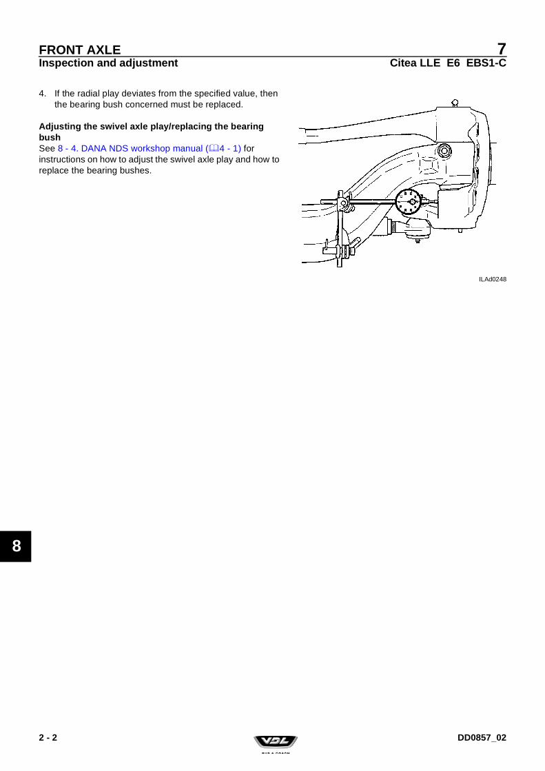
7Citea LLE E6 EBS1-C
FRONT AXLEInspection and adjustment
8
4. If the radial play deviates from the specified value, then the bearing bush concerned must be replaced.
Adjusting the swivel axle play/replacing the bearing bushSee 8 - 4. DANA NDS workshop manual (4 - 1) for instructions on how to adjust the swivel axle play and how to replace the bearing bushes.
ILAd0248
2 - 2 DD0857_02

7Citea LLE E6 EBS1-C
FRONT AXLEInspection and adjustment
8
2.2 AXLE TILT: CHECKING AND ADJUSTING
General information• The vehicle should be placed on a flat and horizontal sur-
face and the steering mechanism should be in the middle position.
• The axle tilt can be measured using an angle meter or wheel alignment equipment.
Inspection of the axle tilt using a graduated arc1. Clean the place where the graduated arc is placed on the
axle pad.
2. Place the graduated arc on a longitudinal chassis beam and check whether the chassis is parallel to the floor.If this is not the case, the axle tilt should be corrected by the chassis position.
3. Place the graduated arc on the axle pad and measure the angle. Compare the measured value to the specified value (see 0 - 6.1 General information (6 - 1)).
4. Also measure the axle tilt on the other side of the axle.If different values are measured, the front axle mounting should be inspected for deviations.
Inspecting the axle tilt using wheel alignment equipment1. Use high-quality wheel alignment equipment for the
inspection. This equipment must be calibrated regularly must preferably be calibrated before every measure-ment.
2. Follow the instructions for the alignment equipment and work accurately.Compare the measured value to the specified value (see 0 - 6.1 General information (6 - 1)).
ILAd0249
2 - 3DD0857_02

7Citea LLE E6 EBS1-C
FRONT AXLEInspection and adjustment
8
2.3 WHEEL CAMBER AND KINGPIN INCLINATION (KPI): CHECKING
Comment:Only the camber is measured in the following measurement. If the camber is correct, then the kingpin inclination is also correct.
General information• The vehicle should be placed on a flat and horizontal sur-
face and the steering mechanism should be in the middle position.
• The tyre pressure should be correct.• The vehicle must be unloaded.• The camber can be measured using a graduated arc or
wheel alignment equipment.• The measurement should be carried out on both wheels.
Checking the camber using a graduated arc1. Clean the side of the wheel rim. Place the angle meter
against the wheel rim. Keep the angle meter in the verti-cal position.
2. Read the angle. For the correct angle, see 0 - 6.1 General information (6 - 1).
Checking the camber using wheel alignment equipment1. Use high-quality wheel alignment equipment for the
inspection. This equipment must be calibrated regularly must preferably be calibrated before every measure-ment.
2. Follow the instructions for the alignment equipment and work accurately. For the permitted angle, see 0 - 6.1 General information (6 - 1).
The following situations can cause the measured value to deviate:• Excessive swivel axle bearing play.• A bent front axle; in that case, the kingpin inclination will
also deviate from the specified value.
ILAd0088
2 - 4 DD0857_02

7Citea LLE E6 EBS1-C
FRONT AXLEInspection and adjustment
8
2.4 TOE: INSPECTING AND ADJUSTING
General information• The toe should be measured using wheel alignment equip-
ment.• The vehicle must be unloaded.• The measurement must be taken with the wheels on the
ground.• The steering mechanism must be in the middle position.
Inspecting the toe1. Use high-quality wheel alignment equipment for the
inspection. This equipment must be calibrated regularly must preferably be calibrated before every measure-ment.
2. Follow the instructions for the alignment equipment and work accurately. See 0 - 6.1 General information (6 - 1) for the correct information.
3. Make sure the steering mechanism is free of tension.Therefore, try to drive the vehicle in a straight line to the measuring location. If this is not possible, then the vehi-cle must be driven backwards and forwards at the meas-uring location with the steering mechanism in the middle position.
4. Measure the toe of the axle.
Adjusting the toe1. Unscrew the retaining clip bolts until the track rod can be
rotated.
2. Set the track rod A to the correct length by extending or shortening it (see 0 - 6.1 General information (6 - 1)). Track rod B can be adjusted using the nuts which have an interior and an exterior screw thread. Both nuts must be rotated an equal distance.
3. Clean and check the retaining clip bolts. Replace the bolts if they are rusty or damaged. Replace the self-lock-ing nut.
4. Tighten the retaining clip bolts to the specified torque (see 0 - 6.2 Tightening torques (6 - 4)).
5. Check the toe again.
If a large deviation is measured, the cause should be traced. The deviation could, for example, be caused by a collision which has bent some components. In this case, the other steering mechanism components should also be carefully inspected.
ILAd0250
The threaded end for the coupling balls must not be screwed too far out of the track rod. The end of the coupling ball’s screw thread must not be visible in the slot (see the diagram).
2 - 5DD0857_02

7Citea LLE E6 EBS1-C
FRONT AXLEInspection and adjustment
8
6. Check whether the retaining clips tocu the axle beam at the maximum wheel turning angle. If necessary, rotate the retaining clips.
ILAd0252
2 - 6 DD0857_02

7Citea LLE E6 EBS1-C
FRONT AXLEInspection and adjustment
8
2.5 WHEEL TURNING ANGLE: INSPECTING AND ADJUSTING
Inspecting the wheel turning angle1. Apply the vehicle’s parking brake and place chocks in
front of and behind the rear wheels.
2. Jack up the front axle and place turning plates under the centre of the wheels.Only use turning plates which allow for wheeldisplacement caused by the wheel roll radius.
3. Place the wheels in the “straight ahead” position and lower the wheels until they rest on the turning plates. Zero the turning plates.
4. Turn the steering wheel fully to the right until the stop is reached and check the wheel turning angle to the right (see 0 - 6.1 General information (6 - 1)).
5. Turn the steering wheel fully to the left until the stop is reached and check the wheel turning angle to the left (see 0 - 6.1 General information (6 - 1)).
Adjusting the wheel turning angle1. The wheel turning angle is adjusted by changing the
length of the stop bolts (x2) on the swivel axle. Use the lock nuts to lock the bolts after making the adjustment.
2. After finishing the adjustment, check that the tyre does not come into contact with other components.
3. If the wheel turning angle has been changed, make sure to adjust the steering box’s poppet valves (see 3 - 3.1 Poppet valves: inspecting and adjusting (3 - 1)).
Work safely and block the vehicle so that it cannot slide off the turning plates.
ILAd0091
2 - 7DD0857_02

7Citea LLE E6 EBS1-C
FRONT AXLEInspection and adjustment
8
2.6 STEERING ROD: INSPECTING AND ADJUSTING
Inspecting the setting of the steering rod1. Apply the vehicle’s parking brake and place chocks in
front of and behind the rear wheels.
2. Jack up the front axle and place turning plates under the centre of the wheels.Only use turning plates which allow wheel displacement caused by the wheel roll radius.
3. Place the wheels in the “straight ahead” position and lower the wheels until they rest on the turning plates.
4. Place the wheel to which the steering rod is connected in the “straight ahead” position. Do this with the aid of align-ment equipment.
5. Check whether the steering box is exactly in the middle position using the marks on the steering box (see the dia-gram).
6. In the case of a deviation, adjust the length of the steer-ing rod.If a large deviation is measured, the cause should be traced.The deviation may, for example, have been caused by a collision which bent some components.In this case, the other steering mechanism components should also be carefully inspected.
Adjusting the steering rod1. Unscrew the bolt of the retaining clip on the steering rod.
2. Remove the steering rod from the steering arm (see 8 - 3.2 Steering rod: removing and installing (3 - 5)).
3. Place the steering box in the middle position by aligning the marks.
Work safely and block the vehicle so that it cannot slide off the turning plates.
ILAe0337
ILAd0252
2 - 8 DD0857_02

7Citea LLE E6 EBS1-C
FRONT AXLEInspection and adjustment
8
4. Set the steering rod to the correct length by screwing the ball joint in or out.When the vehicle is unloaded, unscrew the ball joint one extra revolution.
5. Check the ball joint’s screw thread for damage.
6. Fit the steering rod into the steering arm (see 8 - 3.2 Steering rod: removing and installing (3 - 5)).
7. Clean and check the retaining clip’s bolt. Replace the bolts if it is rusty or damaged. Replace the self-locking nut.
8. Tighten the lock nut to the specified torque (see 0 - 2.2 Tightening torques (2 - 3)).
9. Check whether the steering wheel is in the middle posi-tion.If the steering wheel is not in the middle position, then the following must be carried out:• Remove the steering shaft from the steering column’s
output shaft.• Check whether the steering box is in the middle posi-
tion.• Turn the steering wheel so that the marks on the steer-
ing wheel and the steering column's output shaft are aligned.
• Next, fit the steering shaft to the steering column’s out-put shaft without changing the settings.
ILAd0250
The threaded end for the coupling balls must not be screwed too far out of the track rod. The end of the coupling ball’s screw thread must not be visible in the slot (see the diagram).
If the length is not correct because the ball joint can only be rotated a full turn, get as close as possible to the correct length. A steering rod that is too long is preferable to a steering rod that is too short.
Fitting a new self-locking nut on a ball joint with a damaged screw threadcan lead to a dangerous situation.
ILAe0337
2 - 9DD0857_02

7Citea LLE E6 EBS1-C
FRONT AXLEInspection and adjustment
8
2.7 STEERING MECHANISM: INSPECTING THE HINGED POINTS
General points of attention1. Check whether all the locks of the pitman arm, steering
rod and track rod are present and undamaged.
2. Check whether there is any play on the spider of the steering box’s input shaft.
3. Check the clamped connection of the steering rod and the track rod for deformation. Replace if any deformation is observed.
4. Visually check the steering rod/track rod for damage. If serious damage is observed, the steering rod/track rod must be replaced.
ILAe0006
1 Cover2 Top bearing shell3 Housing4 Compression spring5 Threaded stud6 Ball joint7 Diaphragm spring8 Bottom bearing shell9 Bellows10 Clamping ring
2 - 10 DD0857_02

7Citea LLE E6 EBS1-C
FRONT AXLEInspection and adjustment
8
Checking the steering rod balls and track rod balls1. The checks must be made in the operational condition
with a loaded axle.
2. Clean the steering rod balls and the track rod balls with a dry cloth (do not use a cleaning product or a solvent).
3. Visually check the steering rod balls and the track rod balls for:a. Corrosion.
The steering rod/track rod ball housing, the threaded stud and the cover must not have any grooves deeper than 1 mm.
b. Cover deformationCheck the cover for deformation. If deformation of the cover is observed, the steering rod/track rod must be replaced.
c. Bellows/dust coverCheck whether grease escapes via the wall of the bellows by squeezing the bellows by hand. It is per-mitted for grease to escape through the bottom bel-lows opening. The bellows must not have any holes, cracks or worn areas.
d. Diaphragm spring and clamping ringThe diaphragm spring and clamping ring push the bellows against the steering ball housing and the ball joint.Check whether the diaphragm spring and the clamp-ing ring lay correctly in the recesses. It must not be possible to rotate the bellows/dust cover by hand.
e. Castellated nut and split pinCheck the attachment of the castellated nut and the split pin. Check the castellated nut and the split pin for excessive corrosion.
f. Steering rod/track rod clamped connectionThe clamping screw must be correctly fitted. The nut must be flush against the saddle clamp and must not be visibly deformed. Pitting caused by corrosion with a depth greater than 0.5 mm is not permitted. If it is observed that the clamped connection is loose or has been loose, the steering rod and the track rod must be replaced as a precaution. Replace excessively corroded screws and nuts.
Traces of rust on the underside of the steering rod/track rod are an indication of a loose clamped con-nection.
Place a finger on the clamped connection, turn the steering wheel from left to right and check whether the clamped connection moves. If movement is observed, the steering rod and the track rod must be replaced.
g. Steering rod/track rod ball joint screw threadCheck the ball joint’s screw thread for damage before fitting a new nut.Tighten a new nut on the ball joint by hand.
ILAe0242
2 - 11DD0857_02

7Citea LLE E6 EBS1-C
FRONT AXLEInspection and adjustment
8
Replace the ball joint if the new nut cannot be screwed on to the screw thread by hand.
Checking the radial (sideways) steering rod/track rod play
1. Check the pivot points whilst the engine is not running.
2. Turn the wheels to the “straight ahead” position.
3. Make sure the weight of the vehicle rests on the front wheels.
4. Push and pull the steering rod/track rod by hand in the direction of the steering rod/track rod ball joints. Do not use any tools to apply force, because this may damage the components. The steering rod/track rod ball joints must be replaced if any radial play can be felt.
Checking the loaded axial steering rod/track rod play1. Check the pivot points whilst the engine is not running
and with a load placed on the axles.
2. Turn the steering wheel to the left and the right.
3. Check the compression of the steering rod/track rod ball joint. Compare the measured value to the maximum per-mitted steering rod/track rod ball joint play (see 0 - 2.1 Steering box (2 - 1)).If necessary, replace the steering rod/track rod ball joint.
4. If in doubt, check the unloaded axial steering rod/track rod ball joint play.
Fitting a new nut on a ball joint with a damaged thread may lead to a dangerous situation.
Always check the play on the ball joints whilst the engine is not running. When the engine is running, the forces on the steering rod/track rod become so great (due to the resistance between the tyre and the road) that the ball is pushed upwards against the pressure of the spring, so that play is unjustly observed.
ILAe0007
There must always be a small amount of axial play. This is normal.
If there is no axial play, then there is rust and/or dirt between the ball joint and the housing. This is not permitted.
2 - 12 DD0857_02

7Citea LLE E6 EBS1-C
FRONT AXLEInspection and adjustment
8
Checking the unloaded axial steering rod/track rod play1. Use the special tool (VDL Bus & Coach no. 41329426) to
check the steering rod/track rod ball joint axial play.
2. First, jack up the axle until the wheels come off the ground and place the axle on axle supports.
3. Make sure the castellated nut’s (if fitted) split pin does not come into contact with the head of the threaded stud.
4. Put the special tool together using the correct parts.
5. Screw the thrust nut (8) on to the threaded spindle.
6. Fit the spring retainer (3), the spring (4) and the thrust bush (6) into the bracket (1).Fit the lock screw (5). The thrust bush must be able to move freely.
CommentFit the correct thrust bush (6). The thrust bush (6) must touch the outside edge of the steering ball joint (7).
7. Screw back the thrust bolt (2) until the thrust bush (6) and its flange lay against the bracket (A = 0 mm).
8. Fit the special tool over the steering rod/track rod ball joint (7) and turn the threaded spindle (9) by hand until the special tool clamps on to the steering rod/track rod ball joint (7).
9. Tighten the thrust bolt (2) until its head lays against the bracket (1).
10. Using a feeler gauge, measure the clearance "A" created between the thrust bush and the bracket.Compare the measured value to the maximum permitted steering rod/track rod ball joint play (see 0 - 2.1 Steering box (2 - 1)). If necessary, replace the steering rod/track rod ball joint.
ILAk0001
2 - 13DD0857_02
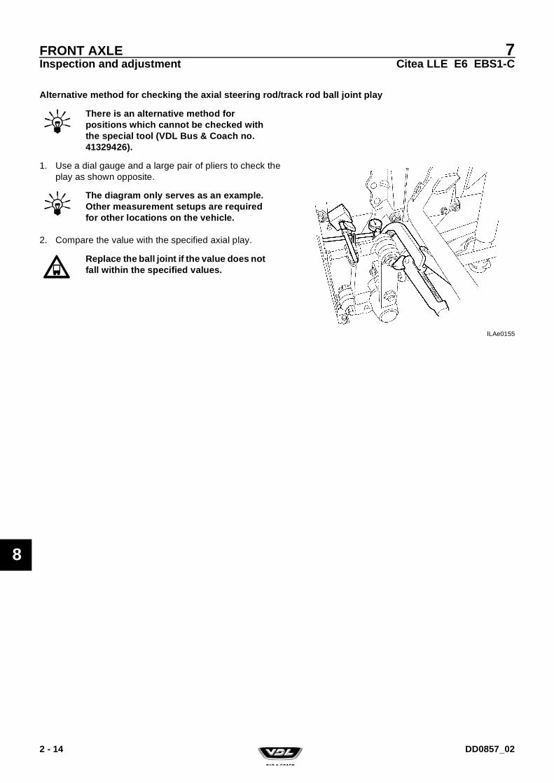
7Citea LLE E6 EBS1-C
FRONT AXLEInspection and adjustment
8
Alternative method for checking the axial steering rod/track rod ball joint play
1. Use a dial gauge and a large pair of pliers to check the play as shown opposite.
2. Compare the value with the specified axial play.
There is an alternative method for positions which cannot be checked with the special tool (VDL Bus & Coach no. 41329426).
ILAe0155
The diagram only serves as an example. Other measurement setups are required for other locations on the vehicle.
Replace the ball joint if the value does not fall within the specified values.
2 - 14 DD0857_02

7Citea LLE E6 EBS1-C
FRONT AXLEInspection and adjustment
8
2.8 FRONT AXLE BEAM: INSPECTING
General informationIt is recommended to check the axle beam if the vehicle has been in an accident or if abnormal deviations are measured when checking the wheel positions.
A number of the measurements given below can also be car-ried out with the aid of alignment equipment. For more infor-mation, see the instruction manual provided with the alignment equipment.
See 0 - 7. Special tools (7 - 1) for the special tool.
Checking the front axle beam1. Remove the front axle from the vehicle and remove both
swivel axles.
2. Place a straight edge over the axle pads of the front axle beam and check whether the axle pads are aligned with each other.
3. Place the straight edge over both axle pads and check whether they are parallel to each other.
4. Place the two measurement rods in the swivel axle holes. Place a straight edge with a graduated arc on the axle pad. Measure the angle of the measurement rods with regard to the axle pads. The measured angle must be 90º.
ILAd0254
ILAd0255
2 - 15DD0857_02

7Citea LLE E6 EBS1-C
FRONT AXLEInspection and adjustment
8
5. Measure the kingpin inclination (KPI) by placing a straight edge with a graduated arc on top of the axle pads. The angle can be read by making the graduated arc's ruler parallel to the measurement rods.
6. If a deviation is observed with one of the inspections, then the axle beam must be replaced.
ILAd0256
It is not permitted to straighten the front axle beam. This may affect the material strength.
2 - 16 DD0857_02

7Citea LLE E6 EBS1-C
FRONT AXLEInspection and adjustment
8
2.9 TYRE PRESSURE AND TYRE LOAD CAPACITY: CHECKING
The highly differentiated vehicle programme offered by VDL Bus & Coach, the continuous developments in tyre technol-ogy and the importance of safety, return and comfort have led to VDL Bus & Coach drawing up the following guidelines for determining the tyre load capacity and the tyre pressure.
2.9.1 VERIFYING THE TYRES HAVE A SUFFICIENT LOAD CAPACITY
The correct tyres are fitted when the vehicle leaves the fac-tory after manufacture. The following points are relevant for inspection during the entire lifespan of the vehicle.
Verifying the load capacity1. Look at the left-hand column of the vehicle type plate for
the maximum permitted axle loads which the vehicle is or will be registered for in a certain country.
2. Look at the tyre for the specified maximum load capacity. This is stated in kg and lbs (14). The load capacity is stated on each tyre for single assembly and double assembly axles. The stated load capacities apply to the highest permitted tyre speed. This speed can be recog-nized on the tyre by the highest stated speed symbol (7). This symbol consists of a capital letter, for example L. Here, a maximum speed of 120 km/h is applicable. If the axle loads according to point 2.1.1.1 are the same as or less than the sum of the load capacities stated on the tyres on the axle concerned and the vehicle’s speed lim-iter is set to a speed equal to or less than the highest speed index stated on the tyre, then the tyres have a suf-ficient load capacity.
The owner of the vehicle is responsible for ensuring that suitable tyres are fitted to the vehicle.The driver is responsible for ensuring the tyres have the correct tyre pressure and the load capacity of each axle/tyre is not exceeded.
ILAz0274
ILAd0382
2 - 17DD0857_02

7Citea LLE E6 EBS1-C
FRONT AXLEInspection and adjustment
8
3. If, according to the inspection explained in 2.1.1.2, the tyres appear to have an insufficient load capacity, then the following inspection must be carried out.• Check whether the vehicle’s speed limiter is set to a
lower speed than the highest speed index on the tyre. This limited speed is then translated into a tyre speed index. Besides the highest load index, it is possible for a lower load index to also be stated on the tyre together with a speed symbol (8). The load index consists of two 3-figure numbers separated by a slash or a dash, which is a code for the load capacity of a tyre in a sin-gle/double assembly. The load capacity that corre-sponds to the code can be found in a load index table. This table is given in the technical catalogue and/or on the tyre supplier’s website.
• This makes it possible to still prove that the tyres fitted to the vehicle have a sufficient load capacity. If a sec-ond speed index is not stated on the tyre and the speed limiter is set to a speed lower than the speed index stated on the tyre, then, in many cases where the speed limiter is set to a speed of less than 100 km/h, the load capacity may be raised to the values stated in the ETRTO standards table, which specifies the rela-tionship between the maximum permitted speed and the maximum permitted load capacity. In special cases, a tyre manufacturer may also give an extra dec-laration that the load capacity may exceed the value stated in the table.
4. By carrying out 2.1.1.1 and 2.1.1.3, it is possible to come to a conclusion as to whether tyres with a sufficient load capacity have been fitted to the vehicle. In the case where the conclusion is based on a declaration issued by the tyre manufacturer, it is recommended to include this declaration with the vehicle documents.
ILAd0382
2 - 18 DD0857_02

7Citea LLE E6 EBS1-C
FRONT AXLEInspection and adjustment
8
2.9.2 VERIFICATION OF THE CORRECT TYRE PRESSURE
Verifying the tyre pressure1. The tyre supplier’s tables show the specified tyre pres-
sure for the maximum permissible axle weight that is stated in the left-hand column of the vehicle type plate. If this tyre pressure is observed, then the tyre pressure will not be too low.
2. However, it is possible that the use of the vehicle remains restricted to considerably lower axle weights than the maximum permissible axle weight that is stated in the left-hand column of the vehicle type plate. You can have this checked for VDL buses by requesting an axle weight calculation from VDL, accompanied by a diagram which states the seating plan, the number and position of the standing locations and the weight and position of the lug-gage area. The weights from this calculation can then be used to find the specified tyre pressure in the tables pro-vided by the tyre manufacturer for the vehicle use.
3. 2.1.2.1 and 2.1.2.2 give the opportunity to set the tyre pressure to the highest axle weights. However, it is pos-sible that the highest axle weights may not occur very often. As long as an installation for automatically adjust-ing the tyre pressure to the load is not fitted to the vehicle, the owner of the vehicle, in his combined functions of the person with the knowledge of the use of the vehicle and the person responsible for ensuring the vehicle has the correct tyre pressure, should consider deviating from the tyre pressure given according to 2.1.2.1 and 2.1.2.2 and apply a lower tyre pressure. It goes without saying that
ILAd0284
2 - 19DD0857_02

7Citea LLE E6 EBS1-C
FRONT AXLEInspection and adjustment
8
this should only be decided after consulting with the tyre manufacturer, vehicle manufacturer and the contract partner in the case of a tyre contract. The owner could then decide to state the tyre pressure he decided to use on a sticker on the wheel arches above the axles con-cerned.
General information1. The stated tyre pressures are for cold tyres.
2. A lot of tyre wear is caused by the fact that the tyre pres-sure does not correspond to the axle load.
3. For a double assembly:– The pressure must be the same for both tyres.– The depth of tread must be almost the same.
4. A too high or too low tyre pressure causes the tyres to wear quickly and may have an adverse effect on the vehicle’s steering and mounting.
5. Vehicles equipped with ABS:The following faults in the tyres may cause the vehicle’s ABS braking system to partially or completely stop oper-ating:– Excessive tyre wear.– Too low tyre pressure.– Tyres which do not match or which are incorrectly fit-
ted.
6. Use an accurate tyre pressure gauge to check the tyre pressure of every tyre on the vehicle and, if necessary, change the tyre pressure to the value stated in the tyre pressure table.
7. Make sure all the tyre valves are in good condition and have a valve cap.
2 - 20 DD0857_02

7Citea LLE E6 EBS1-C
FRONT AXLEInspection and adjustment
8
2.10 TYRES AND RIMS: INSPECTING
Inspecting the tyres1. Check the depth of the tread. The advised minimum
depth for road safety is 1 mm. The wear indicator in the tyre is at a tread depth of 1.6 mm. (The legally permitted tread depth may vary per country.)
2. Check the side walls for incisions, damage (caused by manhole covers, pavements, etc.), wear caused by rub-bing and abnormal deformation.
3. Check the tread for incisions, local deformation and for-eign objects (stones, nails, etc.).
4. Check whether the wear pattern on the tread is evenly distributed over the entire surface.
Comment:Possible causes of uneven wear are:– Incorrect tyre pressure.– Play in the spring mounting, swivel axles, steering ball
joints and reaction rods.– The vehicle’s axles not being aligned.– Deviating wheel positions, etc.
It is important to trace the cause of abnormal tyre wear, for example, by aligning the vehicle.
Inspecting the wheel rims1. Inspect the wheel rims for the following:– Deformation of the edges of the rims and the wheel disc.
For a double assembly, also inspect the inside wheel.– Deformation of or cracks in the wheel bolt holes.– Corrosion, including on the tyre side of the rim and the rim
ring.
2. Cracked or damaged wheel rims or wheel rims with cracked or deformed wheel bolt holes must be replaced.It is not permitted to weld wheel rims or to repair them in any other way. In time, the dynamic load will cause the weld to crack.
3. To prevent damage to the tyre and/or indirect tension cracks (because of notching) due to corrosion, the wheel rim’s anti-corrosion treatment should remain fully intact. See Group 0 of the Workshop Instruction Manual for instructions on how to remove rust and repair paint dam-age.Before respraying, remove the old layer of paint to pre-vent the total paint thickness from becoming too great.
ILAd0023
When removing a damaged wheel rim from the vehicle, deflate the tyre (remove the tyre valve) to remove any tension in the wheel rim.
2 - 21DD0857_02
7Citea LLE E6 EBS1-C
FRONT AXLEInspection and adjustment
8
The total layer thickness must not be greater than 50 microns.
With a total paint layer thickness (wash primer and paint) of more than 50 microns, the pretension of the wheel bolts may be reduced after this layer has been crushed. This could result in the wheel nuts coming loose.
2 - 22 DD0857_02

7Citea LLE E6 EBS1-C
FRONT AXLEInspection and adjustment
8
2.11 WHEEL RIMS: INSPECTING
General information1. Inspect the wheel rims for the following points:
• Deformation of the edges of the rims.For a double assembly, also inspect the inside wheel.
• Deformation or cracks of the wheel bolt holes.• Corrosion, including on the tyre side of the rim and the
rim ring.
2. Cracked or damaged wheel rims or wheel rims with cracked or deformed wheel bolt holes must be replaced.It is not permitted to weld wheel rims or to repair them in any other way.In time, the dynamic load will cause the weld to crack.
3. To prevent damage to the tyre and/or indirect tension cracks (notching) due to corrosion, the wheel rim’s anti-corrosion treatment should stay fully intact.See "Paint treatment" in Group 0 for instructions on how to remove rust and repair the coat of paint.Before respraying, remove the old paint layer to prevent the total paint thickness from becoming too great. The total paint layer thickness should not exceed 50 microns.
When removing a wheel with a damaged wheel rim, deflate the tyre (remove the tyre valve) to remove any tension in the wheel rim.
With a total paint layer thickness (wash primer and paint) of more than 50 microns, the pretension of the wheel bolts may be reduced after this layer has been crushed. This could result in the wheel nuts coming loose.
2 - 23DD0857_02

7Citea LLE E6 EBS1-C
FRONT AXLEInspection and adjustment
8
2.12 OIL-LUBRICATED/GREASE-LUBRICATED WHEEL HUBS: CHECKING FOR LEAKS
Front axle wheel hubs1. Check the grease-lubricated wheel hubs for leaks.
2. If serious traces of grease are observed on new or recently fitted wheel hubs, then this may indicate exces-sive use of assembly grease.
3. If the wheel hubs were not recently fitted, serious traces of grease may indicate a leak from the bearing unit. This means that the entire bearing unit must be replaced.
2 - 24 DD0857_02

7Citea LLE E6 EBS1-C
FRONT AXLEInspection and adjustment
8
2.13 WHEEL SPEED SENSOR: INSPECTING
1. Connect the diagnosis tool.
2. Select the "Wheel speed sensor" function in the EBS application.
3. Check the minimum (Vmin) and maximum (Vmax) peak voltage of all the wheel speed sensors at a speed of 5 km/h.Compare the Vmin values with the specified values (see 0 - 6.1 General information (6 - 1)).
4. Check whether the Vmax/Vmin ratio exceeds the permis-sible ratio (see 0 - 6.1 General information (6 - 1)).
5. If there are deviating measurement results, check the fol-lowing:• The sensor ring (1) for damage and contamination.
Even the most minute damage can cause a fault. If the sensor ring is damaged, then the entire wheel bearing unit must be replaced.
• The movement of the sensor (2).If the sensor does not move, remove, clean and refit it.Never use a hammer to tap the sensor into the swivel axle. This may damage both the sensor and the sensor ring.
• Wheel bearing play.• Tyre size.• Wheel speed sensor wiring.• Wheel speed sensor resistance value.• The operation of the EBS system.
ILAh0066
2 - 25DD0857_02

7Citea LLE E6 EBS1-C
FRONT AXLEInspection and adjustment
8
2 - 26 DD0857_02

7Citea LLE E6 EBS1-C
FRONT AXLERemoval and installation
8
3. REMOVAL AND INSTALLATION
3.1 WHEEL: REMOVING AND FITTING
CommentsThe rims and wheel nuts used on the vehicle are of the wheel hub centring type.DO NOT use any other type of rim or wheel nut.Characteristics of wheel hub centring are:• Wheels with cylindrical holes.• Wheel nuts with a separate, non-removable, flat thrust
washer.• Wheels where the rim lies tightly against the cams of the
wheel hubs.
Tightening the wheel nuts1. Remove the plastic cap from each wheel nut.
2. Use a torque spanner to tighten the wheel nuts to the cor-rect torque (see 0 - 6.2 Tightening torques (6 - 4)) in the order shown in the diagram.
3. Refit the plastic caps.
Removing and fitting the wheels
General information– Only use original VDL Bus & Coach wheel rims permitted
for the vehicle concerned.– Make sure the same type of tyre and rim of the same size
are fitted on both sides of the axle.– The tread depth of both tyres must be approximately the
same, certainly on a vehicle equipped with EBS.For a vehicle equipped with EBS, the difference in tyre diameter on the front and rear axle(s) must not be greater than 14%.
ILAd0471
The rims and wheel nuts used on the vehicle are of the wheel hub centring type. DO NOT use any other type of rim or wheel nut.
When fitting new wheel bolts, the wheel nuts must be retightened twice. The first time after 100 km and the second time after 500 km.
ILAd0025
When removing a wheel with a cracked or damaged wheel rim, always deflate the tyre first (remove the tyre valve) to remove any tension in the wheel rim.
3 - 1DD0857_02

7Citea LLE E6 EBS1-C
FRONT AXLERemoval and installation
8
The ABS will not work if the tyre diameters differ by too much.
– Always observe the specified load index and speed index for the tyres.
– Insufficient cleaning of the contact surfaces and/or uneven tightening of the wheel nuts may cause vibrations during driving or braking.
– When one wheel bolt needs replacing, the other wheel bolts on the same tyre must also be replaced.
Removing the disc wheel1. Use a wire brush to clean the screw thread of the wheel
bolts.
2. Lightly lubricate the screw thread of the wheel nuts with oil.
3. Unscrew the wheel nuts.
4. Place a jack as close as possible to the wheel which is going to be replaced. Only use a suitable jack point (see Group 0).
5. Jack up the vehicle and place axle supports under the vehicle. Only use the intended support points (see Group 0).
6. Remove the wheel nuts and take the wheel off the hub.
Installing the disc wheel1. Carefully clean the wheel hub’s fitting face, the cams on
the wheel hubs and the inside edge of the tyre to be fitted by removing dirt, rust, burrs and paint residue from the edge with a scraping iron. Rub the fitting edges clean and dry. If necessary, apply a new layer of paint.
ILAd0026
3 - 2 DD0857_02

7Citea LLE E6 EBS1-C
FRONT AXLERemoval and installation
8
2. Apply a thin layer of grease to the wheel hub’s fitting edge and the top of the wheel hub cams
3. Also apply a thin layer of grease to the wheel rim’s fitting edge. This grease layer should prevent the wheel rim and the wheel hub from rusting together.
4. Check whether the contact surfaces of the wheel rim and the wheel hub are clean. If necessary, clean them.
5. Fit the wheel.
6. Clean the wheel nuts and then apply a drop of oil between the thrust washer and the wheel nut.
7. Clean the wheel bolts and apply a drop of oil to the first turn of the screw thread.
8. Fit the wheel nuts and tighten them evenly in the order shown in the diagram.A pneumatic spanner may be used, but the torque will not be very reliable.It will, therefore, be necessary to retighten the wheel nuts to the specified torque using a torque spanner. See 0 - 6.2 Tightening torques (6 - 4) for the specified torque.
9. Check the tyre pressure.
10. If larger tyres or wheel rims have been fitted, first make sure they do not come into contact with other compo-nents. If necessary, re-adjust the wheel turning angle (see 8 - 2.5 Wheel turning angle: inspecting and adjusting (2 - 7)).
ILAd0027
ILAd0028
ILAd0025
The use of COPASLIP or MOLYKOTE is not permitted.
Wheel nuts must always be tightened and retightened when they are cold. However, tightening wheel bolts in extreme cold should be avoided.
3 - 3DD0857_02

7Citea LLE E6 EBS1-C
FRONT AXLERemoval and installation
8
11. Use a torque spanner to retighten the wheel nuts after 100 km. If new wheel nuts are fitted, retighten the wheel nuts again after 500 km.
3 - 4 DD0857_02

7Citea LLE E6 EBS1-C
FRONT AXLERemoval and installation
8
3.2 STEERING ROD: REMOVING AND INSTALLING
Removing the steering rod1. Remove the split pin on both sides of the steering rod and
then remove the castellated nut.
2. Remove the ball joints from the steering arm and the pit-man arm using a ball joint extractor.
Installing the steering rod1. If fitting a new steering rod, copy the settings of the old
steering rod.
2. Clean the conical contact surfaces of the steering rod balls, the steering arm and the pitman arm. The conical surfaces must be completely free of dirt, grease and paint.
3. Fit the steering rod.
4. Check the steering rod’s setting and, if necessary, adjust it (see 8 - 2.6 Steering rod: inspecting and adjusting (2 - 8)).
5. Make sure the ball joint’s screw thread is screwed far enough into the steering rod.The end of the coupling ball’s screw thread must not be visible in the slot (see the arrow in the diagram).
6. Check whether the retaining clip’s bolt has been tight-ened to the specified torque (see 0 - 2.2 Tightening torques (2 - 3)).
7. Tighten the castellated nuts to the specified torque (see 0 - 2.2 Tightening torques (2 - 3)).If the ball joint’s split pin hole is not aligned with the recesses in the castellated nut, the castellated nut should be tightened further.
8. Fit new split pins.
ILAe0084
ILAd0252
3 - 5DD0857_02

7Citea LLE E6 EBS1-C
FRONT AXLERemoval and installation
8
3.3 TRACK ROD: REMOVING AND INSTALLING
Removing the track rod1. Remove the split pin and the castellated nut on both
sides of the track rod.
2. Remove the ball joints from the steering arms using a ball joint extractor.
Installing the track rod1. If a new track rod is being fitted, copy the settings of the
old track rod.
2. Clean the conical contact surfaces of both the track rod balls and the swivel axles.The conical surfaces should be absolutely free of dirt, grease and paint.
3. Fit the track rod and tighten the castellated nuts to the specified torque.
4. Check the axle’s toe-in and, if necessary, adjust it (see 8 - 2.4 Toe: inspecting and adjusting (2 - 5)).
5. Make sure the ball joint’s threaded stud is screwed far enough into the track rod.The end of the coupling ball’s screw thread must not be visible in the slot (see the arrow in the diagram).
6. Check whether the bolts of the retaining clips have been tightened to the specified torque (see 0 - 2.2 Tightening torques (2 - 3)).
7. Tighten the castellated nuts to the specified torque (see 0 - 2.2 Tightening torques (2 - 3)).If the ball joint’s split pin hole is not aligned with the recesses in the castellated nut, the castellated nut should be tightened further.
8. Fit new split pins.
ILAe0084
ILAd0252
3 - 6 DD0857_02

7Citea LLE E6 EBS1-C
FRONT AXLERemoval and installation
8
3.4 FRONT AXLE: REMOVING AND INSTALLING THE COMPLETE FRONT AXLE
Removing the complete front axle1. Allow the vehicle to kneel unconditionally on the bumpers
using the "Kneeling" contra plug (VDL Bus & Coach no. 40950157) (see 0 - 7. Special tools (7 - 1))
2. Unscrew the wheel nuts on both sides of the axle, but do not remove the nuts just yet.
3. Hoist the vehicle and support it at the front by placing hoisting sheers under the chassis (see Group 0, "Jacking and lifting instructions").
4. Remove the wheel nuts and remove the wheels from the axle.
5. Check whether the brake chambers are pressureless by connecting an open test line to the test connection. Remove the brake hoses from the brake chambers at the T-piece.
6. Disconnect the ABS connectors (B220/B221).
7. Disconnect the brake pad wear indicator connectors (B297/B298).
8. Disconnect the steering rod.
9. Disconnect the rod for the height control valve (1) at the same side as the axle.
10. Remove the bolts of the lower torque rods (2) on the same side as the axle.
11. Safely support the front axle and remove the bolts (5).
12. Lower the axle (3) to the floor. Make sure the front axle does not tip over. Make sure no parts are damaged.
13. Support the pneumatic suspension brackets (5) after the front axle has been removed.
ILAd0258
ILAd0259
Make suitable assembly and disassembly sheers so that the front axle cannot tip over.
3 - 7DD0857_02

7Citea LLE E6 EBS1-C
FRONT AXLERemoval and installation
8
Installing the complete front axle1. Check all the nuts and bolts for rust and damage. If nec-
essary, replace them. If they are reused, thoroughly clean the screw thread and remove any paint.
2. Fit the axle from under the vehicle and centre it using the centring pins.
3. Fit the front axle's attachment bolts and tighten them to the specified torque (see 0 - 6.2 Tightening torques (6 - 4)).
4. Fit the steering rod in the steering arm (see 8 - 3.2 Steering rod: removing and installing (3 - 5)).
5. Connect the pneumatic brake lines.
6. Connect the ABS connectors (B220/B221).
7. Connect the brake pad wear indicator connectors (B297/B298).
8. Fit the lower torque rods.
9. Fit the height control valve pin.
10. Fit the wheels (see 8 - 3.1 Wheel: removing and fitting (3 - 1)).
11. Lower the vehicle to the ground. Remove the kneeling contra plug (special tool).
12. Check the operation of the pneumatic suspension and the brake system.
ILAd0260
3 - 8 DD0857_02

7Citea LLE E6 EBS1-C
FRONT AXLEDANA NDS workshop manual
8
4. DANA NDS WORKSHOP MANUAL
For more information, see DD0014_xx on the VDL Bus & Coach Documentation Portal.
4 - 1DD0857_02

7Citea LLE E6 EBS1-C
FRONT AXLEDANA NDS workshop manual
8
4 - 2 DD0857_02

7Citea LLE E6 EBS1-C
CENTRAL LUBRICATION SYSTEM
9
CENTRAL LUBRICATION SYSTEM
DD0857_02

7Citea LLE E6 EBS1-C
CENTRAL LUBRICATION SYSTEM
9
DD0857_02

7Citea LLE E6 EBS1-C
CENTRAL LUBRICATION SYSTEMDescription of the central lubrication system
9
1. DESCRIPTION OF THE CENTRAL LUBRICATION SYSTEM
For more information, see DD0552_xx on the VDL Bus & Coach Documentation Portal.
1 - 1DD0857_02

7Citea LLE E6 EBS1-C
CENTRAL LUBRICATION SYSTEMDescription of the central lubrication system
9
1 - 2 DD0857_02