wood elements tension - forest products … material tested according to standard methods. 2 for a...
TRANSCRIPT

U.S. DEPARTMENT OF AGRICULTURE • FOREST SERVICE • FOREST PRODUCTS LABORATORY • MADISON,WIS In Cooperation with the University of Wisconsin
U. S. FOREST SERVICE RESEARCH NOTE
FPL-0150
JANUARY 1967
A HORIZONTAL MACHINE FOR TESTING STRUCTURAL WOOD ELEMENTS IN TENSION

Abstract
The building industry's extensive use of 1- and 2-inch-thick lumber as tension members in laminated beams and trusses has resulted in an increased need for evaluations of the axial tensile strength properties of such lumber in structural sizes. To meet this demand, the Forest Products Laboratory designed and built a horizontal-type testing machine of 75-ton capacity. The machine has met all requirements, providing a facility for the accurate, efficient, safe, and economical generation of tensile properties of structural size members.
Included in the design are such features as a single I-beam base frame for supporting the specimen and loading devices; a hydraulic jack loading system: beveled wedge-shaped grips to apply lateral pressure against the specimen as load increases, and yet minimize stress concentrations; a load-indicating system accurate to within 1 percent of true load; and a movable screen to enclose the specimen during operation of the machine, for the protection of the technicians and observers.
Basic design and performance requirements are discussed and design features of the new machine are described and illustrated.

A HORIZONTAL MACHINE FOR TESTING STRUCTURAL
WOOD ELEMENTS IN TENSION
By
K. H. BOLLER, Engineer
1Forest Products Laboratory, Forest Service U.S. Department of Agriculture
Introduction
The increasing use of nominal 1- and 2-inch-thick boards and lumber in tension in laminated beams and trusses has necessitated investigations of the axial tensile strength and related properties of such lumber in structural sizes. Previously, tensile properties of structural lumber were approximated from flexural strength of structural timbers and from the strength of small, clear straight-grained material tested according to standard methods.2 For a time, testing of full-size members was hampered by the inability to grip them without damage. Test method development was advanced when the gripping systems for the structural tension specimens, such as steel plates bonded to the wood or roughened steel plates bolted together with sufficient pressure to prevent slipping, were abandoned in favor of a more simple method--that of using wedges for lateral pressure and a beveled contact surface for relief of stress concentrations. 3
At the Laboratory another big problem in evaluating structural-size lumber was the lack of a suitable testing machine. Some preliminary results had been obtained in the million-pound capacity machine, but it had shortcomings for this work--as well as being otherwise needed. Clearly a new machine had to be built to perform the necessary number of evaluations of structural-size material.
1Maintained at Madison, Wis., in cooperation with the University of Wisconsin. 2American Society for Testing and Materials. Standard Methods of Testing Small Clear Speci
mens of Timber. ASTM D 143-52. 3Bohannan, Billy. Exploratory Development of Tension Test Method for Structural-Size Lumber.
U.S. Forest Service Research Paper FPL 40. Forest Products Laboratory. 1965.
FPL-0150

Figu
re
1.--
Gen
eral
vi
ew
of
the
horiz
onta
l-ty
pe
test
ing
mac
hine
de
sign
ed
and
built
by
th
e Fo
rest
P
rodu
cts
Labo
rato
ry
for
eval
uatio
n of
te
nsile
st
reng
th
prop
ertie
s of
st
ruct
ural-s
ize
lum
ber.
The
mov
able
sc
reen
th
at
cove
rs
the
spec
imen
du
ring
test
ha
s be
en
rolle
d ba
ck
at
each
en
d.
M
131
929

Therefore a new horizontal-type tension testing machine was designed and built at the Laboratory. It was designed so the required evaluations could be conducted fast, at low cost, and with convenience and safety for the operators. A detailed description of the machine is presented here, with a discussion of the design requirements, features, and performance capabilities.
Basic Design Requirements
Basic ideas and features governing the design of the new machine included the following:
1. A means for gripping the test member at the ends and subjecting it to a tensile load so that the tensile forces in sections between grips are axial and uniformly distributed throughout the cross sections without flexure.
2. A drive mechanism for imparting a uniform, controlled velocity to a movable grip.
3. An accurate load-indicating mechanism, capable of showing the total tensile force on the test section of the specimen with less than 1 percent error.
4. A capacity adequate for testing specimens of the following nominal dimensions: thicknesses of 1 and 2 inches; widths of 4, 6, and 8 inches; and lengths of 8, 10, 12, 14, and 16 feet. For common structural grades of lumber in these sizes, it is estimated the tensile load capacity of the machine should be 150,000 pounds.
5. Wedge-shaped grips to provide an automatic increase in lateral pressure on the test specimen as the longitudinal tensile load increases. The surfaces of the grips in contact with the test specimen are to be beveled in accordance with the design selected from previous exploratory work.-3
6. Grips that are as nearly self-alining as possible under load.
7. A device for measuring the elongation of the test section of the specimen with respect to specific paired gage points. The gage points are to be symmetrically located on the lengthwise surface of the specimen, as far apart as feasible; the minimum spacing would be twice the larger cross-sectional dimension of the test specimen from each jaw edge. Two pairs of such gage points, on diametrically opposite sides of the specimen, should be used to permit one observer to measure the average deformation.
FPL-0150 -3

8. The grips, test specimen, and extensometer are to be located at approximately waist height above the floor level to insure ready access for installation, observation, and removal of the specimen and all devices by the operators.
9. A movable screened enclosure around the test specimen between grips, for the protection of operators and observers.
Description of Machine and Components
To meet the load and performance requirements, the horizontal tension testing machine consisted of the following principal components: a base frame, devices for load application and sensing, grips, connecting linkages and rods, extensometer, and a protective screen.4 The individual components are described in the succeeding paragraphs and are illustrated in figures 1 to 10.
Base Frame
A single I-beam 27 inches deep by 29 feet long, with 14-inch-wide flanges, was selected as the base frame for supporting the test specimen and loading devices. This size I-beam provided the desired working height and adequate overall strength and stiffness to resist the bending moment caused by eccentric loading. In addition, the upper 14-inch-wide flange provided an excellent surface for supporting the load mechanism and grips.
Load Application
The drive mechanism for the movable head was a hydraulic jack of 100-ton capacity (50,000 pounds greater than the design capacity of the machine); it was 16-1/2 inches high and had a 10-inch stroke. The 100-ton jack was mounted in a framework of 3-1/2 by 12-inch channel irons which, in turn, were bolted to the 14-inch-wide top flange of the base I-beam (fig. 2). The centerline of the jack was 8 inches above the 14-inch-widetop flange. This is also the centerline height of all grips and specimens.
The applied force was transmitted to a movable head or "evener" 5 by 5 by 23 inches long. The ends of the evener were 3 inches in diameter to accommodate 3-inch-diameter eyes attached to the ends of 1-7/8-inch-diameter tension rods.
4 DetaiI drawings of the horizontal-type tension testing machine are available upon request.
FPL-0150 -4
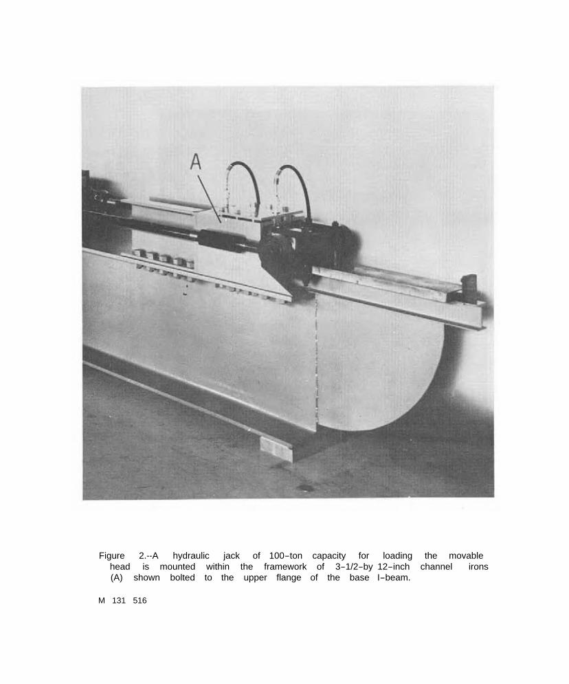
Figure 2.--A hydraulic jack of 100-ton capacity for loading head is mounted within the framework of 3-1/2-by 12-inch (A) shown bolted to the upper flange of the base I-beam.
the movable channel irons
M 131 516

Figu
re
3.--
A v
iew
of
th
e pr
essu
re
cons
ole
and
the
read
-out
ap
para
tus
of
the
elec
troni
c lo
ad
cell,
sh
owin
g:
A
pres
sure
co
nsol
e;
B
switc
hing
an
d ba
lanc
ing
unit;
an
d C
di
gita
I st
rain
in
dica
tor,
calib
rate
d so
th
at
its
mic
roin
ch
stra
in
read
ings
re
pres
ent
the
tens
ile
load
in
po
unds
on
th
e sp
ecim
en.
M 1
32 0
21

The travel of the jack was only 10 inches and this required provision for up to 24 inches of additional travel so that large specimens could be inserted in the grips.
Hydraulic pressure was applied by an oil pump having a capacity of 10,800 pounds per square inch and pressure was registered on a precision (±1 percent error) oil pressure indicator (fig, 3). Normally, only an oil pump and indicator are used with lapped rams where the indicator is an accurate measure of load, usually within ± 1 percent error. The 100-ton jack, however, had a static friction of from 750 to 2,000 pounds and, therefore, an auxiliary electronic load indicator was used.
Load Indicator
The stationary head and reaction of the loading system were essentially the same as those at the movable end of the system. The only exception was that the stationary head included a 100-ton-capacity, single bridge electronic load cell instead of a hydraulic jack within the 3-1/2- by 12-inch channel irons. The load on the specimen, as sensed by the load cell, was observed by the combination of a switching and balancing unit and a digital strain indicator (fig. 3). The strain indicator was calibrated so that its microinch strain readings represented the load on the specimen in pounds. The error of this load-indicating system is less than ±1 percent of the true load.
Grip Assemblies
The grips (fig. 4) are the heart of the loading mechanism, Each consists of outer steel plates, outer and inner wood wedges, and steel coatings on the wedges. The two outer plates are 1- by 14- by 40-inch steel plates held 16 inches apart by twelve 1-inch bolts. Between these plates and fastened to them are outer wooden wedges cut at 12° to the plane of the 1-inch steel plates. The inclined planes between outer and inner wedges are covered with 1/4-inch-thick steel plates to provide a sliding plane for matched inner wooden wedges with steel facings. The inner wedges are movable and have one surface parallel to and in contact with the outer wedges, and one parallel to and in contact with the flat surface of the specimen.
Coatings on these various surfaces are important. The inclined plane between the two 1/4-inch plates must be ground flat and smooth and lubricated with oil, Molyeote, or graphite to allow free motion. The surface of the inner wedge in
FPL-0150 -7

Figu
re
4.--
The
tens
ile
grip
s ar
e w
edge
sh
aped
an
d be
vele
d to
ap
ply
late
ral
pres
sure
ag
ains
t th
e sp
ecim
en
and
yet
min
imiz
e st
ress
co
ncen
tratio
ns.
M
132
018

Figure 5.--Schematic showing design details of the tensile grips.
M 129 100

contact with the specimen must be roughened or coated with a sandpaper grit glued to 1/4-inch steel plates. This latter contact surface is 14 inches long, plus a beveled portion 8 inches in length having a slope of 0.40 inch in 8 inches (fig. 5).
This assembly functions as follows: the longitudinal motion of the specimen pulls the inner wedges in the direction of the applied force. The inner wedges, due to the 12° slope, press tightly against the specimen with increased longitudinal movement. The movement of the wedges must be uniform, that is, without momentary freezing and slipping, When the specimen fails, the energy that was stored in the specimen is now released and drives the inner wedges in the opposite direction, releasing their grip on the specimen and stopping at the rubber bumper. The force of this impact usually moves the entire grip and rod assembly.
Since each of the massive grip assemblies weighs over 500 pounds, they would not float freely on the I-beam without some auxiliary device. Various axes of rotation and a spring suspension simulate floating grips. Compression springs are located at one extremity of each outer stationary wedge (fig. 6). Each spring supports about 150 pounds and deflects 0.0179 inch per pound of load. The rod supporting the spring extends to a wheel for a rolling support in any horizontal posit ion.
At the other extremity of the grip, the tension rods, clevises, and pins 3 inches in diameter by 23 inches long are supported by a three-wheel dolly, as shown in figure 7. The point of contact is the center of the 3- by 23-inch pin. There is no spring at this point. The centerline of the pin is a fixed 8 inches above the top 14-inch flange of the I-beam. The effect of this suspension system is illustrated in figure 8 and may be summarized by pointing out the provision for rotation of the grip about three axes as follows: (A) about the lengthwise axis of the specimen; (B) about an axis perpendicular to the flat side of the specimen; and (C) about an axis perpendicular to the thin side of the specimen. The lengthwise axis goes through the center of the cross section of the specimen, the second axis is about 12 inches from the end of the specimen, and the third is about 8 feet from the end of the specimen (fig. 8).
Extensometer
An extensometer (fig. 9) was designed and built to meet the established requirements. It consists of an inverted U-shaped frame which envelops the cross section of the specimen and supports one pair of gage points, an averaging lever, a spring, and the dial indicator. The spring supports the averaging lever
FPL-0150 -10
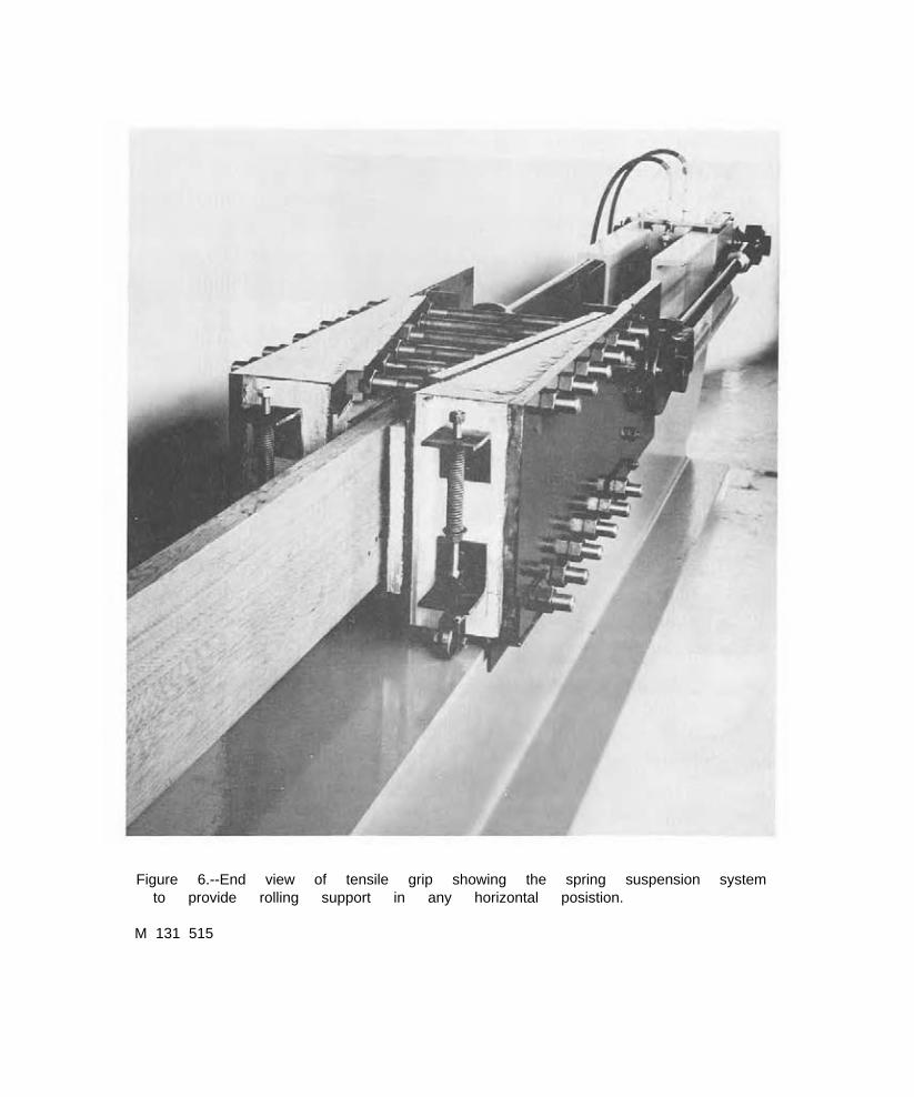
Figure 6.--End view of tensile grip showing the spring suspension system to provide rolling support in any horizontal posistion.
M 131 515


Figure 8.--Schematic showing the three axes of the gripping system: A about the lengthwise axis of the specimen; B about an axis perpendicular to the flat side of the specimen; and C about an axis perpendicular to the thin side of the specimen.
M 131 571

Figure 9.--Extensometer assembly mounted in position on specimen, showing: A inverted lever (C) and dial with brads at the the specimen.
U-shaped indicator
other set
frame; (D); of g
B and age
spring E taut
points n
supporting wire c
ear the
the averaging onnecting the opposite end of
lever
M 132 020

and dial and provides tension to the fine wire connecting the lever with brads at the other pair of gage points located near the other end of the specimen, The dial senses the average movement of the brads at one set of gage points with respect to the gage points at the inverted “U”.
Protective Screen
Since failures of test specimens are quite violent and groups of wood fibers snap like taut strings, flying splinters are sometimes encountered. To shield the operators and observers, a protective enclosure was built around the specimen between grips (fig. 10). It was built in two 8-foot sections and provided with wheels that roll along the bottom 14-inch flange of the I-beam. Each screen is easily rolled back and forth to enclose the specimen and yet allow accessibility to working parts of the test apparatus.
Cushioning
To absorb and reduce the shock load transmitted to the floor upon failure of the test specimen, the base I-beam was mounted on two cushioning pads of 2-inch-thick cork placed between the lower flange of the I-beam and the floor.
FPL-0150 -15-

Figu
re
10.--
A
wire
ca
ge
devi
ce,
built
in
tw
o m
ovab
le
sect
ions
, en
clos
es
the
spec
imen
du
ring
test
, fo
r th
e pr
otec
tion
of
oper
ator
s an
d ob
serv
ers.
M 1
31 9
28

Summary
The horizontal-type tension testing machine designed and built by the Forest Products Laboratory met all objectives and design requirements. The machine provides an efficient facility for conducting evaluations of tensile strength properties of structural size lumber relatively fast, easily, and safely.
The grips provide axial alinement of clear material and rotate freely when eccentrically located knots are present. The hydraulic loading system provides a uniform, controllable velocity of the movable head, and the electronic weighing system provides an accurate measurement of the tensile load. The face width of the grips, the distance between faces, and the distance between the movable and the stationary grips are such that various structural specimens, ranging in size from 1 to 2 inches thick, 4 to 10 inches wide, and 8 to 16 feet long, can be tested provided the load does not exceed 150,000 pounds.
The grips are wedge shaped and beveled to automatically apply lateral pressure against the specimen and yet minimize s t r e s s concentrations. An extensometer accurately provides an average measurement of strain in the specimen between the grips, permitting one observer to read and record the elongation.
Finally, the entire work area in which the operators must handle the specimens and extensometer and observe data provides for efficient operation. All of these features aid in the accurate, safe, and economical generation of tensile properties of structural size members.
FPL-0150 -17 1.5-18