wood-burning stoves - hearth n homedownloads.hearthnhome.com/...1011u_broc_woodstoves.pdf · key...
TRANSCRIPT
W O O D - B U R N I N G S T O V E S

TRUE CRAFTSMANSHIP
Vermont Castings was founded on the belief that the stately
beauty of cast iron could be combined with the simple utility of
wood heat, to craft stoves of value and enduring beauty.
Among the vibrant hills and silver waters of the Green Mountain
State is one constant: the promise of American craftsmanship.
This is where day after day, year after year, the proud people of
Vermont Castings craft each stove with hand and heart.
Vermont Castings provides more than heat. It’s the warmth that
unites. The timeless designs and furniture-quality finish set the
scene for intimate memories. No detail is too small, no element
insignificant. This is true craftsmanship.

Key Technologies
Our unique, built-in thermostat requires no electricity and automatically adjusts the required air for combustion. Just set the
stove for the heat output you want and let the thermostat do the rest. The result—longer, more even heat.
THERMOSTATICALLY CONTROLLED COMBUSTION
FlexBurn stoves burn with or without a catalyst and achieve 15% higher efficiency on low burns with the catalyst in place.
FlexBurn® Technology
S TA R T U P
• Primary burn started and fueled by fresh air
• Bypass damper is open
2 - S TA G E B U R N
• Damper is closed once stove and flue are sufficiently hot,
forcing smoke into the secondary combustion chamber
• Additional air feeds combustion of gases for secondary burn
3 - S TA G E B U R N
• With catalyst in place, increased efficiency and lower
emissions result from a tertiary burning of gases and CO
• The catalyst also enables combustion at much lower
temperatures, extending burn times and saving on fuel costs
S A V E M O N E Y A N D U S E L E S S
W O O D W I T H A C ATA LY S T
Increase your heating efficiency and lower your stove emissions,
ensuring you get the most out of each load of wood.
Top Load TechnologyOur top load technology is second to none and perhaps the most celebrated
feature of Vermont Castings stoves.
Top loading lends itself to numerous conveniences and safety features:
• The top load design increases load capacity by allowing you to utilize the
entire fire box; load the firebox right to the top for longer burns
• Top loading is safer and cleaner, keeping ash and embers contained
• The smokeless design releases less smoke in your room than loading
from the front
• Direct heat to the stovetop results in a superior cooking surface

Defiant FlexburnW O O D - B U R N I N G S T O V E
KEY FEATURES
Timeless cast iron styling with a furniture-quality finish
Exclusive swing-out ash pan allows you to cleanly remove ashes, even when the stove is hot
Convenient top load keeps smoke and ash contained and increases load capacity
Cast iron griddle top offers a versatile cooking surface for the stovetop chef
FlexBurn Technology
Top LoadTechnology
Thermostatically Controlled Combustion

KEY FEATURES
Timeless cast iron styling with a furniture-quality finish
Exclusive swing-out ash pan allows you to cleanly remove ashes, even when the stove is hot
Convenient top load keeps smoke and ash contained and increases load capacity
Encore FlexburnW O O D - B U R N I N G S T O V E
Cast iron griddle top offers a versatile cooking surface for the stovetop chef
FlexBurn Technology
Top LoadTechnology
Thermostatically Controlled Combustion
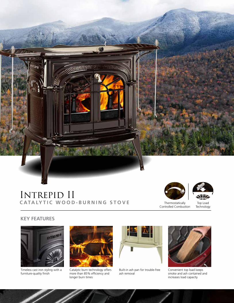
Intrepid IIC ATA LY T I C W O O D - B U R N I N G S T O V E
KEY FEATURES
Timeless cast iron styling with a furniture-quality finish
Built-in ash pan for trouble-free ash removal
Catalytic burn technology offers more than 85% efficiency and longer burn times
Convenient top load keeps smoke and ash contained and increases load capacity
Top LoadTechnology
Thermostatically Controlled Combustion

AspenN O N - C ATA LY T I C W O O D - B U R N I N G S T O V E
KEY FEATURES
Timeless cast iron styling with a furniture-quality finish
North-south orientation for easy loading
Built-in ash pan for trouble-free ash removal
Top plate cooking surface
Thermostatically Controlled Combustion
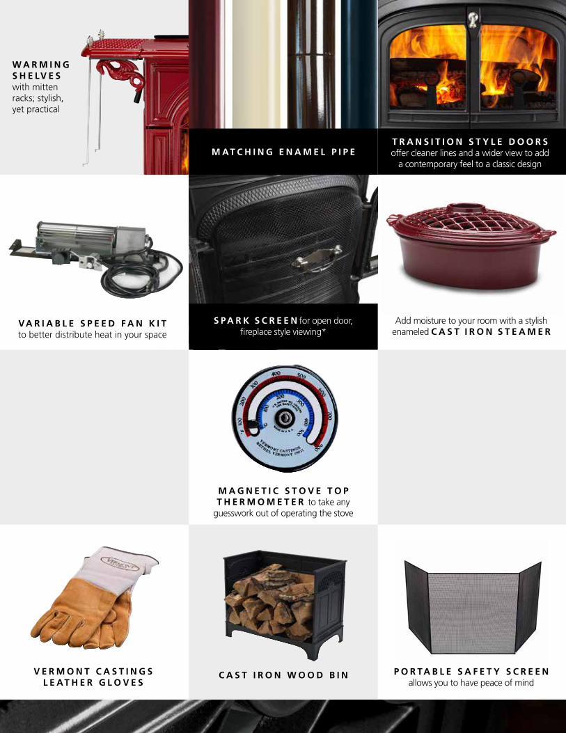
W A R M I N G S H E LV E S with mitten racks; stylish, yet practical
VA R I A B L E S P E E D F A N K I T to better distribute heat in your space
T R A N S I T I O N S T Y L E D O O R S offer cleaner lines and a wider view to add
a contemporary feel to a classic design
Add moisture to your room with a stylish enameled C A S T I R O N S T E A M E R
M A G N E T I C S T O V E T O P T H E R M O M E T E R to take any
guesswork out of operating the stove
C A S T I R O N T R I V E T for stove top cooking
V E R M O N T C A S T I N G S L E AT H E R G L O V E S
O U T S I D E A I R A D A P T E R
C A S T I R O N W O O D B I N
M AT C H I N G E N A M E L P I P E
S PA R K S C R E E N for open door, fireplace style viewing*
P O R TA B L E S A F E T Y S C R E E N allows you to have peace of mind

Stove Finishes
Option & Accessories
C L A S S I C B L A C K A V A I L A B L E O N :
Defiant Flexburn
Encore Flexburn
Intrepid II
Aspen
O P T I O ND E F I A N T
F L E X B U R NE N C O R E
F L E X B U R NI N T R E P I D I I A S P E N
Warming Shelves • • •Enamel Finish Pipe • • • •Transition Doors • • •Variable Speed Fan Kit • •Spark Screen* • • •Cast Iron Steamer • • • •Cast Iron Trivet • • • •Stove Top Thermometer • • • •Outside Air Adapter • • • •Leather Gloves • • • •Cast Iron Wood Bin • • • •Portable Safety Screen • • • •
B O R D E A U XE N A M E L A V A I L A B L E O N :
Defiant Flexburn
Encore Flexburn
Intrepid II
M A J O L I C A B R O W N E N A M E L A V A I L A B L E O N :
Defiant Flexburn
Encore Flexburn
Intrepid II
B I S C U I T E N A M E L A V A I L A B L E O N :
Defiant Flexburn
Encore Flexburn
Intrepid II
T W I L I G H TE N A M E L A V A I L A B L E O N :
Defiant Flexburn
Encore Flexburn
*Spark screen requires 8-inch pipe on Defiant or Encore
D E F I A N T F L E X B U R N
E N C O R E F L E X B U R N
I N T R E P I D I I A S P E N
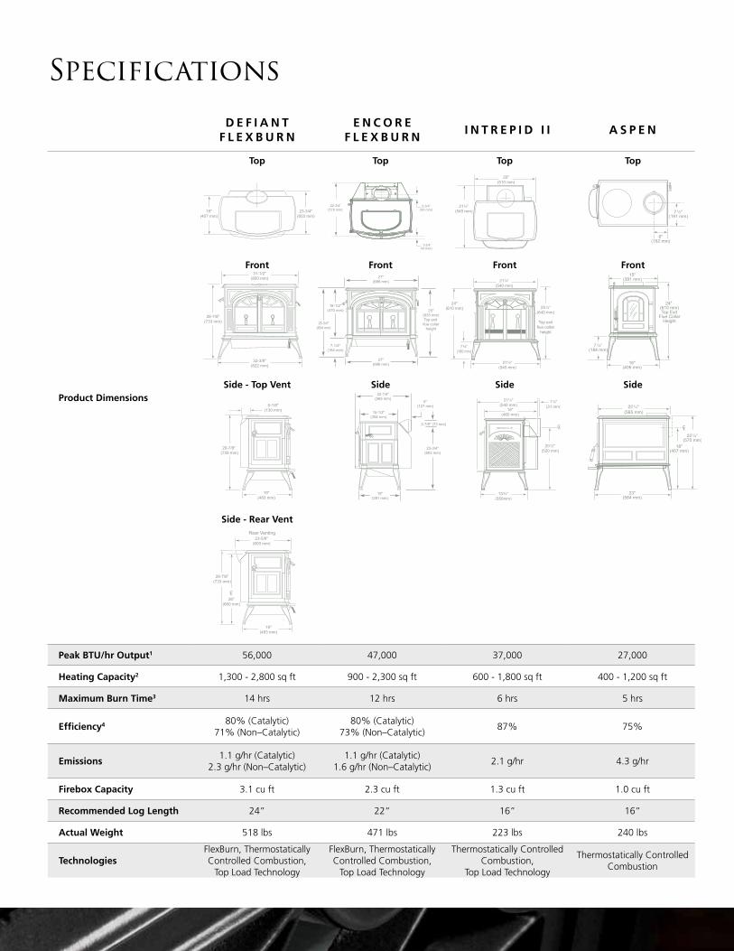
Product Dimensions
Peak BTU/hr Output1 56,000 47,000 37,000 27,000
Heating Capacity2 1,300 - 2,800 sq ft 900 - 2,300 sq ft 600 - 1,800 sq ft 400 - 1,200 sq ft
Maximum Burn Time3 14 hrs 12 hrs 6 hrs 5 hrs
Efficiency4 80% (Catalytic)71% (Non–Catalytic)
80% (Catalytic)73% (Non–Catalytic)
87% 75%
Emissions1.1 g/hr (Catalytic)
2.3 g/hr (Non–Catalytic)1.1 g/hr (Catalytic)
1.6 g/hr (Non–Catalytic)2.1 g/hr 4.3 g/hr
Firebox Capacity 3.1 cu ft 2.3 cu ft 1.3 cu ft 1.0 cu ft
Recommended Log Length 24” 22” 16” 16”
Actual Weight 518 lbs 471 lbs 223 lbs 240 lbs
TechnologiesFlexBurn, Thermostatically Controlled Combustion,
Top Load Technology
FlexBurn, Thermostatically Controlled Combustion,
Top Load Technology
Thermostatically Controlled Combustion,
Top Load Technology
Thermostatically Controlled Combustion
Specifications
Side - Rear Vent
Top TopTop Top
25"(635 mm)Top exit flue collar
height
27"(686 mm)
25-3/4"(654 mm)
18-1/2"(470 mm)
7-1/4"(184 mm)
27"(686 mm)
22-1/4"(565 mm)
15-1/2"(394 mm)
5"(127 mm)
2-7/8" (73 mm)
23-3/4"(603 mm)
15"(381 mm)
1-3/4”44 mm)
3-3/4”(95 mm)
22-3/4”(578 mm)
25"(635 mm)Top exit flue collar
height
27"(686 mm)
25-3/4"(654 mm)
18-1/2"(470 mm)
7-1/4"(184 mm)
27"(686 mm)
22-1/4"(565 mm)
15-1/2"(394 mm)
5"(127 mm)
2-7/8" (73 mm)
23-3/4"(603 mm)
15"(381 mm)
1-3/4”44 mm)
3-3/4”(95 mm)
22-3/4”(578 mm)
25"(635 mm)Top exit flue collar
height
27"(686 mm)
25-3/4"(654 mm)
18-1/2"(470 mm)
7-1/4"(184 mm)
27"(686 mm)
22-1/4"(565 mm)
15-1/2"(394 mm)
5"(127 mm)
2-7/8" (73 mm)
23-3/4"(603 mm)
15"(381 mm)
1-3/4”44 mm)
3-3/4”(95 mm)
22-3/4”(578 mm)
Front FrontFront Front
Side - Top Vent SideSide Side
32-3/8"(822 mm)
28-7/8"(733 mm)
31-1/2"(800 mm)
5-1/8"(130 mm)
19"(483 mm)
18"(457 mm)
23-3/4"(603 mm)
29-7/8" (759 mm)
23-5/8"(600 mm)
19"(483 mm)
26"(660 mm)
CL
28-7/8"(733 mm)
Rear Venting
32-3/8"(822 mm)
28-7/8"(733 mm)
31-1/2"(800 mm)
5-1/8"(130 mm)
19"(483 mm)
18"(457 mm)
23-3/4"(603 mm)
29-7/8" (759 mm)
23-5/8"(600 mm)
19"(483 mm)
26"(660 mm)
CL
28-7/8"(733 mm)
Rear Venting
32-3/8"(822 mm)
28-7/8"(733 mm)
31-1/2"(800 mm)
5-1/8"(130 mm)
19"(483 mm)
18"(457 mm)
23-3/4"(603 mm)
29-7/8" (759 mm)
23-5/8"(600 mm)
19"(483 mm)
26"(660 mm)
CL
28-7/8"(733 mm)
Rear Venting32-3/8"
(822 mm)
28-7/8"(733 mm)
31-1/2"(800 mm)
5-1/8"(130 mm)
19"(483 mm)
18"(457 mm)
23-3/4"(603 mm)
29-7/8" (759 mm)
23-5/8"(600 mm)
19"(483 mm)
26"(660 mm)
CL
28-7/8"(733 mm)
Rear Venting

Clearances
1. Minimum stove top to ceiling clearance is 67” (170 cm).2. WARNING: If stove has been installed based on the clearances described above as “Top exit with single wall or double wall connector pipe,” then stove cannot be operated as “Door open with fire screen and damper open” without moving the stove so the clearance meets those described for this type installation.3. Using a listed double wall oval to round connector.
UNPROTECTED SURFACE PROTECTED SURFACE
A
BC G
E
F
D
D
D
D
A
BC G
E
F
D
D
D
D
A
BC G
E
F
D
D
D
D
A
BC G
E
F
D
D
D
D
Stove parallel to wall Stove in corner Stove parallel to wall Stove in corner
1. Minimum stove top to ceiling clearance is 58” (147 cm).2. A ceiling heat shield 24” (610 mm) in diameter and suspended 1” (25 mm) from the ceiling must surround the pipe in installations where chimney penetrates the ceiling.3. The connector pipe heat shield must extend 36” (914 mm) above flue collar.4. Using listed double wall oval to round adapter when installing optional 8” oval flue collar.
UNPROTECTED SURFACE PROTECTED SURFACE
A
B
D
E
F
F
C
C
A
B
D
E
F
F
C
C
A
B
D
E
F
F
C
C
A
B
D
E
F
F
C
C
Stove parallel to wall Stove in corner Stove parallel to wall Stove in corner
1. Minimum stove top to ceiling clearance is 36” (92 cm).2. When a rear heat shield is installed on a top exit stove, the shield insert must be attached to the
shield so the area behind the flue collar on the stove is protected.3. Chimney connector heat shields must extend exactly 24" (610 mm) above the top of the stove. No
shielding can be used on the connector above 24" (610 mm). The unshielded chimney connector above the 24" (610 mm) point must be 13" (330 mm) from an unprotected wall.
4. In top exit installations, this clearance requires the use of the rear stove heat shield with the flue collar cover plate installed.
A S P E N
UNPROTECTED SURFACE PROTECTED SURFACE
PARALLEL INSTALLATION
CORNER INSTALLATION
PARALLEL INSTALLATION
CORNER INSTALLATION
Side (A) Rear (B) Corner (C) Side (D) Rear (E) Corner (F)
No heat shields 24"(610 mm)
13"(330 mm)
13"(330 mm)
16"(406 mm)
9"(229 mm)
8"(203 mm)
Top exit, rear heat
shield, only1
24"(610 mm)
11"(279 mm)
13"(330 mm)
16"(406 mm)
9"(229 mm)
8"(203 mm)
Rear exit, rear heat shield only
24"(610 mm)
11"(279 mm) N/A 16"
(406 mm)9"
(229 mm) N/A
Top exit, rear heat shield,
single wall pipe w/ connector
shields1,2
24"(610 mm)
9"(229 mm)
13"(330 mm)
16"(406 mm)
9"(229 mm)
8"(203 mm)
Top exit, rear heat shield,
double wall pipe1,3
24"(610 mm)
7"(178 mm)
13"(330 mm)
16"(406 mm)
7"(178 mm)
8"(203 mm)
UNPROTECTED SURFACE No Connector Heat Shield
PROTECTED SURFACE with Connector Heat Shield
Stove installed parallel to wall Stove in corner
Stove installed parallel to wall Stove in corner
B
A
E
D
C
C
F
F
B
A
E
D
C
C
F
F
B
A
E
D
C
C
F
F
B
A
E
D
C
C
F
F
I N T R E P I D I I
UNPROTECTED SURFACE PROTECTED SURFACE
PARALLEL INSTALLATION
CORNER INSTALLATION
PARALLEL INSTALLATION
CORNER INSTALLATION
Side (A) Rear (B) Corner (C) Side (D) Rear (E) Corner (F)
No heat shields 24"(610 mm)
30"(762 mm)
20"(508 mm)
12"(305 mm)
16"(406 mm)
10"(254 mm)
Top exit, rear heat shield, single wall
pipe w/ connector shields1,2
24"(610 mm)
16"(406 mm)
12"(305 mm)
12"(305 mm)
9"(229 mm)
10"(254 mm)
Rear exit, rear heat shield only3
24"(610 mm)
14"(356 mm) N/A 12"
(305 mm)9"
(229 mm) N/A
Top exit, rear heat shield, double wall
pipe4
24"(610 mm)
16"(406 mm)
12"(305 mm) N/A N/A N/A
1. Refer to installation manual for alcove installation requirements.2. Shielding for a top exit stove must include the stove rear heat shield insert to protect the area behind the flue collar. 3. Chimney connector heat shields, in an installation that goes through a combustible ceiling, must ex-
tend to 1" (25 mm) below the ceiling heat shield, which is 22" (559 mm) in diameter. The ceiling heat shield should be 24 gauge or heavier sheet metal, centered on the chimney connector, and mounted on noncombustible spacers.
4. Rear exit — horizontal from flue collar directly back through wall.5. In top exit installations, this clearance requires the use of the rear heat shield with the shield insert
installed.
UNPROTECTED SURFACE No Connector Heat Shield
PROTECTED SURFACE with Connector Heat Shield
Stove installed parallel to wall Stove in corner
Stove installed parallel to wall Stove in corner
A
B C
C
F
F
E
DA
B C
C
F
F
E
DA
B C
C
F
F
E
DA
B C
C
F
F
E
D
D E F I A N T F L E X B U R N
Clearances for 6” or 8” connections;
single or double wall pipe
UNPROTECTED SURFACENO CONNECTOR HEAT SHIELD
PROTECTED SURFACE1
WITH CONNECTOR HEAT SHIELD
PARALLEL INSTALLATION
CORNER INSTALLATION
PARALLEL INSTALLATION
CORNER INSTALLATION
Side (A)
Rear2
Corner (D) Side (E)
Rear2
Corner (D)To rear shroud (B)
To back edge of cast (C)
To rear shroud (F)
To back edge of cast (G)
Top exit, single wall connector pipe
21”(521 mm)
15”(381 mm)
21”(521 mm)
5”(127 mm)
5”(127 mm)
3”(76 mm)
9”(229 mm)
5”(127 mm)
Door open with fire screen and damper open (8” chimney
only)2
22”(559 mm)
18”(457 mm)
24”(610 mm) N/A N/A N/A N/A N/A
Top exit, double wall3 connector pipe
21”(521 mm)
15”(381 mm)
21”(521 mm)
5”(127 mm)
5”(127 mm)
3”(76 mm)
9”(229 mm)
2”(51 mm)
Rear exit 21”(521 mm)
10”(254 mm)
16”(407 mm) N/A N/A N/A N/A N/A
E N C O R E F L E X B U R N
Clearances for 6” connections only
UNPROTECTED SURFACENO CONNECTOR HEAT SHIELD
PROTECTED SURFACE1
WITH CONNECTOR HEAT SHIELD
PARALLEL INSTALLATION
CORNER INSTALLATION
PARALLEL INSTALLATION
CORNER INSTALLATION
Side (A) Rear (B) Corner (D) Side (D) Rear (E) Corner (F)
Top exit, 8” single wall connector w/o shields,
vertical flue collar heat shield
19”(483 mm)
20”(508 mm)
18-1/2”( 470 mm)
5”(127 mm)
7”(178 mm)
12”(305 mm)
Rear exit, no flue collar heat shield
22”(559 mm)
12”(305 mm) N/A 11”
(279 mm)12”
(305 mm) N/A
Top exit, double wall connector pipe, vertical flue collar heat shield installed
18”(457 mm)
7”(178 mm)
12”(305 mm)
4”(102 mm)
5”(127 mm)
5”(127 mm)
Top exit, 6” single wall connector w/o shields,
vertical flue collar heat shield
19”(483 mm)
15”(381 mm)
18-1/2”( 470 mm)
5”(127 mm)
7”(178 mm)
12”(305 mm)

vermontcastings.com
Limited Lifetime WarrantyThe strongest in the industry, Vermont Castings provides a limited lifetime warranty on the most important aspects: firebox and heat exchanger. For full warranty details go to VermontCastings.com.
IMPORTANT - READ BEFORE YOU INSTALL! - Refer to the Owner/Installation Manual for complete clearance requirements and specifications. The images and descriptions in this brochure are provided to assist you in product selection only. Vermont Castings is a registered trademark of Hearth & Home Technologies. Product specifications and pricing subject to change without notice. Fireplace, stove and insert surfaces get extremely HOT and can cause burns if touched. Keep a safe distance away. To learn more visit www.vermontcastings.com/fireplacesafety.©2016 Hearth & Home Technologies®, All rights reserved VMT-1011U-0318