notice - hearth n homedownloads.hearthnhome.com/installmanuals/2040_903.pdf · refer to owner’s...
TRANSCRIPT
1SimpliFire • SF-WM58, SF-WM70, SF-WM94 • 2040-903 Rev. L • 1/17
Model(s):
WARNING: To reduce risk of fi re, electrical shock, or personal injury, read all instructions before using appliance.
Owner’s ManualInstallation and Operation
DO NOT DISCARD THIS MANUAL
NOTICE
• Leave this manual with party responsible for use and operation.
DO NOTDISCARD• Important operating
and maintenance instructions included.
• Read, understand and follow these instructions for safe installation and operation.
SF-WM58-BKSF-WM70-BKSF-WM94-BK
READ CAREFULLY BEFORE ATTEMPTING TO ASSEMBLE, INSTALL, OPERATE, OR MAINTAIN THIS PRODUCT.
PROTECT YOURSELF AND OTHERS BY OBSERVING ALL SAFETY INFORMATION. FAILURE TO COMPLY WITH INSTRUCTIONS COULD RESULT IN PERSONAL INJURY AND/OR PROPERTY DAMAGE.
Please contact your SimpliFire dealer or customer/technical support (877-320-0730) with any questions or concerns.
For the location of your nearest SimpliFire dealer, please visit www.hearthnhome.com.
Congratulations!Congratulations on selecting a SimpliFire Electric Fireplace, an elegant and clean alternative to wood & gas burning fi replaces. The SimpliFire electric fi replace you have selected is designed to provide the utmost in safety, reliability, and effi ciency.
Printed in China - Copyright 2017
SimpliFire • SF-WM58, SF-WM70, SF-WM94 • 2040-903 Rev. L • 1/17 2
1 IMPORTANT INSTRUCTIONS
WARNING! Risk of Fire! Risk of Burns!Risk of Electrical Shock!
DO NOT: • Install or operate damaged heater• Modify heater• Operate the heater without fully assembling all
components
Hearth & Home Technologies Inc. disclaims any responsibility for, and the warranty and agency listing will be voided by the above actions.
WARNING! DO NOT operate fireplace before reading and understanding operating instructions. Failure to operate appliance according to operating instructions could cause fire or injury.
WARNING! Improper installation, adjustment, al-teration, service or maintenance can cause injury or property damage. Refer to owner’s information manual provided with this heater.
NOTICE! This appliance is not intended for use as a pri-mary heat source and should not be factored as such in residential heating calculations.
IMPORTANT SAFETY INSTRUCTIONS
SAVE THESE INSTRUCTIONS
When using electrical appliances, basic precautions should always be followed to reduce the risk of fire, electric shock, and injury to persons, including the following:
• Read all instructions before installing this appliance.
• This appliance is hot when in use. To avoid burns, do not let bare skin touch hot surfaces. Keep combustible materials such as furniture, pillows, bedding, papers, clothes, etc. and curtains at least 3 ft. (0.9 m) from the front of the appliance and keep them away from the sides and rear
• Extreme caution is necessary when any appliance is used by or near children or invalids and whenever the appliance is left operating and unattended.
• Do not operate any appliance if it malfunctions. Disconnect power at service panel and have appliance inspected by a reputable electrician before reusing.
• Do not insert or allow foreign objects to enter any ventilaion or exhaust opening as this may cause an electric shock or fire, or damage the appliance.
• To prevent a possible fire, do not block appliance connection fan air intakes or exhaust in any manner.
• A appliance has hot and arcing or sparking parts inside. Do not use it in areas where gasoline, paint, or flammable vapors or liquids are used or stored.
• Use this appliance only as described in this manual. Any other use not recommended by the manufacturer may cause fire, electric shock, or injury to persons.
• Do not operate any appliance with a damaged cord or plug or after the appliance malfunctions, has been dropped or damaged in any manner. Return appliance to authorized service facility for examination, electrical or mechanical adjustment or repair.
• Do not use outdoors.
• The appliance is not intended for use in bathrooms, laundry areas and similar indoor locations. Never locate appliance where it may fall into a bathtub or water container.
• Do not run cord under carpeting. Do not cover cord with throw rugs, runners, or the like. Arrange cord away from traffic areas and where it will not be tripped over. Do not tightly coil cord.
• Always use properly grounded, fused and polarized outlets.
• Always use ground fault protection where required by electrical code.
• To disconnect appliance, turn controls to “OFF” then remove plug from outlet.
• Always disconnect power before performing any cleaning, maintenance or relocation of the appliance.
• To prevent a possible fire, do not burn wood or other materials in this appliance.
• To prevent electrical shock or fire, always use a certified electrician should new circuits be required.
• When transporting or storing the appliance, keep in a dry place free from excess vibration and store to avoid damage.
• Avoid use of an extension cord because an extension cord may overheat and cause a fire. However if you have to use an extension cord, the cord should be No. 14 AWG minimum size and rated to not less than 1875 watts.
3SimpliFire • SF-WM58, SF-WM70, SF-WM94 • 2040-903 Rev. L • 1/17
Safety Alert Key:• WARNING! Indicates a hazardous situation which, if not avoided could result in death or serious injury.• CAUTION! Indicates a hazardous situation which, if not avoided, could result in minor or moderate injury.
Table of Contents
1 IMPORTANT INSTRUCTIONS A. Important Instructions . . . . . . . . . . . . . . . . . . . . . . . . . . . . . 2B. Warranty . . . . . . . . . . . . . . . . . . . . . . . . . . . . . . . . . . . . . . . 4
2 GENERAL INFORMATION A. Appliance Certification . . . . . . . . . . . . . . . . . . . . . . . . . . . . 5B. Unpacking and Inspecting Appliance . . . . . . . . . . . . . . . . 5C. Model and Serial Number Information . . . . . . . . . . . . . . 5
3 GETTING STARTED A. Parts and Hardware . . . . . . . . . . . . . . . . . . . . . . . . . . . . . 6B. Tools and Supplies Needed . . . . . . . . . . . . . . . . . . . . . . . . 6C. Appliance Dimensions . . . . . . . . . . . . . . . . . . . . . . . . . . . . 6D. Location . . . . . . . . . . . . . . . . . . . . . . . . . . . . . . . . . . . . . . . 7E. Clearance to Combustibles . . . . . . . . . . . . . . . . . . . . . . . . 7F. Electrical Supply Circuit Requirements . . . . . . . . . . . . . . . 7
4 INSTALLATION A. Wall Mounting Bracket . . . . . . . . . . . . . . . . . . . . . . . . . . . 8B. Installing Wall Mount Bracket . . . . . . . . . . . . . . . . . . . . . . . 9C. Appliance Installation . . . . . . . . . . . . . . . . . . . . . . . . . . . 11D. Faux Stone Installation . . . . . . . . . . . . . . . . . . . . . . . . . . . 11E. Glass Front Installation. . . . . . . . . . . . . . . . . . . . . . . . . . . 12F. Electrical Connection . . . . . . . . . . . . . . . . . . . . . . . . . . . . 12
5 OPERATING INSTRUCTIONS A. Manual Switch Function . . . . . . . . . . . . . . . . . . . . . . . . . . 13B. Operating by Remote Control. . . . . . . . . . . . . . . . . . . . . . 14C. Resetting Temperature Cutoff Switch . . . . . . . . . . . . . . . . 14
6 MAINTENANCE A. Maintenance . . . . . . . . . . . . . . . . . . . . . . . . . . . . . . . . . . 15B. Cleaning . . . . . . . . . . . . . . . . . . . . . . . . . . . . . . . . . . . . . . 15C. Servicing. . . . . . . . . . . . . . . . . . . . . . . . . . . . . . . . . . . . . . 15D. Service Parts List . . . . . . . . . . . . . . . . . . . . . . . . . . . . . . . 16
SimpliFire • SF-WM58, SF-WM70, SF-WM94 • 2040-903 Rev. L • 1/17 4
SimpliFire™ WARRANTY
Hearth & Home Technologies, on behalf of its brand SimpliFire (”SimpliFire”), extends the following warranty for electric fireplaces that were purchased from a SimpliFire authorized dealer.
WARRANTY COVERAGE:SimpliFire warrants to the original owner of the SimpliFire fireplace, and to any transferee taking ownership of the Simpli-Fire fireplace within one year following the date of original purchase, that the SimpliFire fireplace will be free from defects in materials and workmanship at the time of manufacture. If a SimpliFire fireplace is found to be defective in materials or workmanship during the applicable warranty period, HHT will, at its option, repair or replace the SimpliFire fireplace. SimpliFire, at its own discretion, may fully discharge all of its obligations under such warranties by replacing the product itself or refunding the verified purchase price of the product itself. The maximum amount recoverable under this warranty is limited to the purchase price of the product. This warranty is subject to conditions, exclusions and limitations as described below.
WARRANTY PERIOD:Warranty coverage begins on the date of original purchase. In the case of new home construction, warranty coverage begins on the date of first occupancy of the dwelling or six months after the sale of the product by an independent, authorized SimpliFire dealer/ distributor, whichever occurs earlier. The warranty shall commence no later than 24 months following the date of product shipment from HHT, regardless of the installation or occupancy date.
WARRANTY CONDITIONS:This warranty only covers SimpliFire fireplaces that are purchased through a SimpliFire authorized dealer or distributor. A list of SimpliFire authorized dealers is available on the SimpliFire websites.
WARRANTY EXCLUSIONS:This warranty does not cover the following:• Changes in surface finishes as a result of normal use. As a heating appliance, some changes in color of interior and
exterior surface finishes may occur. This is not a flaw and is not covered under warranty.• Damage to printed, plated, or enameled surfaces caused by fingerprints, accidents, misuse, scratches, melted items,
or other external sources and residues left on the plated surfaces from the use of abrasive cleaners or polishes.• Repair or replacement of parts that are subject to normal wear and tear during the warranty period. These parts
include: paint, batteries and the discoloration of glass.• Damages resulting from: (1) failure to install, operate, or maintain the appliance in accordance with the installation
instructions, operating instructions, and listing agent identification label furnished with the appliance; (2) shipping or improper handling; (3) improper operation, abuse, misuse, continued operation with damaged, corroded or failed components, accident, or improperly/ incorrectly performed repairs; (4) environmental conditions (5) installation or use of components not supplied with the appliance or any other components not expressly authorized and approved by HHT; (6) modification of the appliance not expressly authorized and approved by HHT in writing; and/or (7) interrup-tions or fluctuations of electrical power supply to the appliance.
• Our obligation under this warranty does not extend to the SimpliFire fireplace’s capability to heat the desired space.
This warranty is void if:• The fireplace is subject to or operated in atmospheres contaminated by chlorine, fluorine, or other damaging chemi-
cals.• The fireplace is subjected to or operated in places with prolonged periods of dampness or condensation or weather.
Examples include but are not limited to outdoors, porches, and laundry rooms.• There is any damage to the fireplace or other components due to water or weather damage.
LIMITATIONS OF LIABILITY:• The owner’s exclusive remedy and SimpliFire’s sole obligation under this warranty, under any other warranty, express
or implied, or in contract, tort or otherwise, shall be limited to replacement, repair, or refund, as specified above. In no event will SimpliFire be liable for any incidental or consequential damages caused by defects in the appliance. Some states do not allow exclusions or limitation of incidental or consequential damages, so these limitations may not apply to you. This warranty gives you specific rights; you may also have other rights, which vary from state to state. EXCEPT TO THE EXTENT PROVIDED BY LAW, SIMPLIFIRE MAKES NO EXPRESS WARRANTIES OTHER THAN THE WARRANTY SPECIFIED HEREIN. THE DURATION OF ANY IMPLIED WARRANTY IS LIMITED TO DURATION OF THE EXPRESSED WARRANTY SPECIFIED ABOVE.
B. Warranty
5SimpliFire • SF-WM58, SF-WM70, SF-WM94 • 2040-903 Rev. L • 1/17
Note: The device complies with Part 15 of the FCC Rules. Operation is subject to the following two conditions:
1. This device may not cause harmful interference, and
2. This device must accept any interference received, including interference that may cause undesired operation.
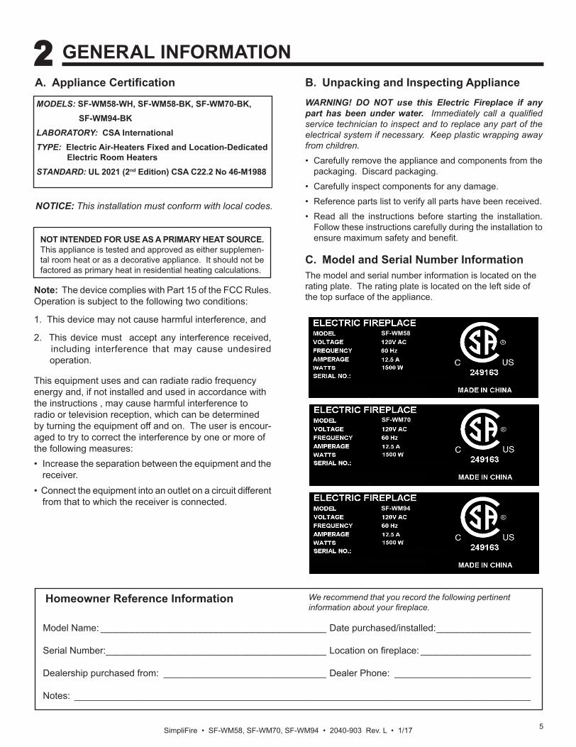
MODELS: SF-WM58-WH, SF-WM58-BK, SF-WM70-BK, SF-WM94-BKLABORATORY: CSA InternationalTYPE: Electric Air-Heaters Fixed and Location-Dedicated Electric Room HeatersSTANDARD: UL 2021 (2nd Edition) CSA C22.2 No 46-M1988
A. Appliance Certification
NOT INTENDED FOR USE AS A PRIMARY HEAT SOURCE. This appliance is tested and approved as either supplemen-tal room heat or as a decorative appliance. It should not be factored as primary heat in residential heating calculations.
NOTICE: This installation must conform with local codes.
2 GENERAL INFORMATION
B. Unpacking and Inspecting Appliance WARNING! DO NOT use this Electric Fireplace if any part has been under water. Immediately call a qualified service technician to inspect and to replace any part of the electrical system if necessary. Keep plastic wrapping away from children.
• Carefully remove the appliance and components from the packaging. Discard packaging.
• Carefully inspect components for any damage.
• Reference parts list to verify all parts have been received.
• Read all the instructions before starting the installation. Follow these instructions carefully during the installation to ensure maximum safety and benefit.
This equipment uses and can radiate radio frequency energy and, if not installed and used in accordance with the instructions , may cause harmful interference to radio or television reception, which can be determined by turning the equipment off and on. The user is encour-aged to try to correct the interference by one or more of the following measures: • Increase the separation between the equipment and the
receiver.• Connect the equipment into an outlet on a circuit different
from that to which the receiver is connected.
C. Model and Serial Number Information The model and serial number information is located on the rating plate. The rating plate is located on the left side of the top surface of the appliance.
SF-WM58
Model Name: ___________________________________________ Date purchased/installed: __________________
Serial Number: __________________________________________ Location on fireplace: _____________________
Dealership purchased from: _______________________________ Dealer Phone: __________________________
Notes: _______________________________________________________________________________________
We recommend that you record the following pertinent information about your fireplace.
Homeowner Reference Information
SF-WM70
SF-WM94
SimpliFire • SF-WM58, SF-WM70, SF-WM94 • 2040-903 Rev. L • 1/17 6
3 GETTING STARTED
Before beginning the installation be sure that the following tools and building supplies are available.Tape measure Pliers Hammer GlovesLevel Magnetic Phillips screwdriver Safety glasses Flat blade screwdriverDrill 5/16 Drill for 3/16 diameter toggle bolts(applicable if installing on drywall-sheathed walls)Masonry Drill 5/16 in. (applicable if installing on masonry walls)
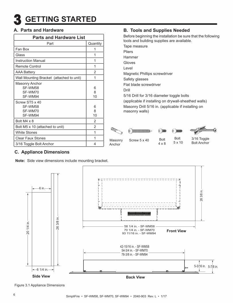
C. Appliance Dimensions
B. Tools and Supplies Needed Parts and Hardware List
Part QuantityFan Box 1Glass 1Instruction Manual 1Remote Control 1AAA Battery 2Wall Mounting Bracket (attached to unit) 1Masonry Anchor SF-WM58 SF-WM70 SF-WM94
68
10Screw ST5 x 40 SF-WM58 SF-WM70 SF-WM94
68
10Bolt M4 x 8 2Bolt M5 x 10 (attached to unit) 2White Stones 1Clear Faux Stones 13/16 Toggle Bolt Anchor 4
A. Parts and Hardware
Masonry Anchor
Screw 5 x 40 Bolt 4 x 8
Bolt5 x 10
42-15/16 in. - SF-WM5854-3/4 in. - SF-WM7078-3/8 in. - SF-WM94
5-3/16 in. 5-7/8 in.
Figure 3.1 Appliance Dimensions
58 1/4 in. - SF-WM58
26 3
/8 in
.
70 1/4 in. - SF-WM7093 11/16 in. - SF-WM94
6 in.
6 1/4 in.
20 1
/4 in
.
26 3
/8 in
.
Side View
Front View
Note: Side view dimensions include mounting bracket.
3/16 Toggle Bolt Anchor
Back View
7SimpliFire • SF-WM58, SF-WM70, SF-WM94 • 2040-903 Rev. L • 1/17
3/16 Toggle Bolt Anchor
D. LocationWhen choosing a location for your fireplace ensure that the general rules are followed:
• For best results, install out of direct sunlight.
• Power supply service must be installed within proximity of electric fireplace prior to finishing to avoid reconstruction.
• See Figure 3.1 for appliance dimensions and to determine location of appliance installation.
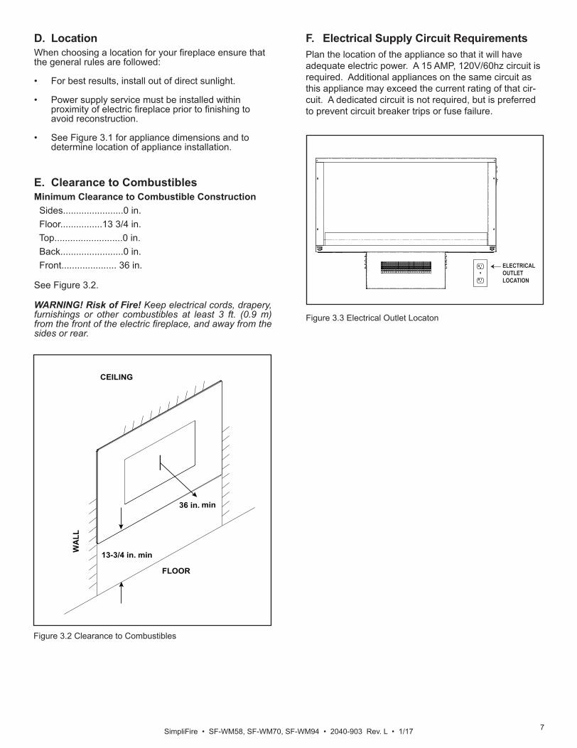
E. Clearance to Combustibles Minimum Clearance to Combustible Construction Sides.......................0 in. Floor................13 3/4 in. Top..........................0 in. Back........................0 in. Front..................... 36 in. See Figure 3.2.
WARNING! Risk of Fire! Keep electrical cords, drapery, furnishings or other combustibles at least 3 ft. (0.9 m) from the front of the electric fireplace, and away from the sides or rear.
F. Electrical Supply Circuit RequirementsPlan the location of the appliance so that it will have adequate electric power. A 15 AMP, 120V/60hz circuit is required. Additional appliances on the same circuit as this appliance may exceed the current rating of that cir-cuit. A dedicated circuit is not required, but is preferred to prevent circuit breaker trips or fuse failure.
FLOOR
WA
LL
CEILING
13-3/4 in. min
36 in. min
Figure 3.2 Clearance to Combustibles
ELECTRICALOUTLETLOCATION
Figure 3.3 Electrical Outlet Locaton
SimpliFire • SF-WM58, SF-WM70, SF-WM94 • 2040-903 Rev. L • 1/17 8
4 INSTALLATION
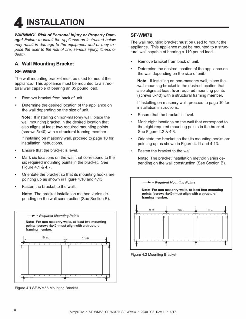
A. Wall Mounting Bracket SF-WM58The wall mounting bracket must be used to mount the appliance. This appliance must be mounted to a struc-tural wall capable of bearing an 85 pound load.
• Remove bracket from back of unit. • Determine the desired location of the appliance on
the wall depending on the size of unit. Note: If installing on non-masonry wall, place the wall mounting bracket in the desired location that also aligns at least two required mounting points (screws 5x40) with a structural framing member. If installing on masonry wall, proceed to page 10 for installation instructions.
• Ensure that the bracket is level.
• Mark six locations on the wall that correspond to the six required mounting points in the bracket. See Figure 4.1 & 4.7.
• Orientate the bracket so that its mounting hooks are pointing up as shown in Figure 4.10 and 4.13.
• Fasten the bracket to the wall. Note: The bracket installation method varies de-pending on the wall construction (See Section B).
WARNING! Risk of Personal Injury or Property Dam-age! Failure to install the appliance as instructed below may result in damage to the equipment and or may ex-pose the user to the risk of fire, serious injury, illness or death.
16 in. 16 in.
Figure 4.1 SF-WM58 Mounting Bracket
= Required Mounting Points
Note: For non-masonry walls, at least two mounting points (screws 5x40) must align with a structural framing member.
16 in. 16 in. 16 in.
Figure 4.2 Mounting Bracket
= Required Mounting Points
SF-WM70The wall mounting bracket must be used to mount the appliance. This appliance must be mounted to a struc-tural wall capable of bearing a 110 pound load.
• Remove bracket from back of unit. • Determine the desired location of the appliance on
the wall depending on the size of unit. Note: If installing on non-masonry wall, place the wall mounting bracket in the desired location that also aligns at least four required mounting points (screws 5x40) with a structural framing member.
If installing on masonry wall, proceed to page 10 for installation instructions.
• Ensure that the bracket is level.
• Mark eight locations on the wall that correspond to the eight required mounting points in the bracket. See Figure 4.2 & 4.8.
• Orientate the bracket so that its mounting hooks are pointing up as shown in Figure 4.11 and 4.13.
• Fasten the bracket to the wall. Note: The bracket installation method varies de-pending on the wall construction (See Section B).
Note: For non-masonry walls, at least four mounting points (screws 5x40) must align with a structural framing member.
9SimpliFire • SF-WM58, SF-WM70, SF-WM94 • 2040-903 Rev. L • 1/17
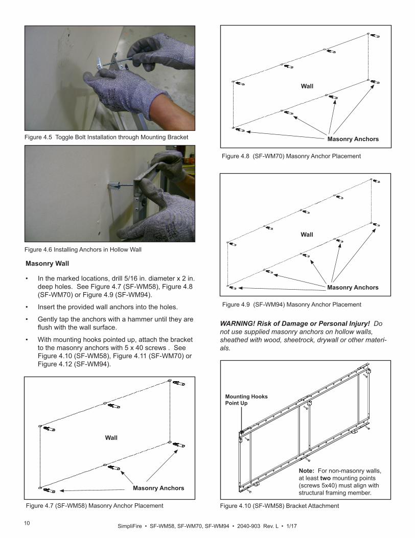
Figure 4.4 3/16 Toggle-Bolt Anchor
• The toggle-bolt anchors are provided to accomodate the required anchor points based on the appliance. Use of toggle bolt anchors requires drywall thick-ness of minimum 1/2 in.
• Insert the bolt through the front side of the mounting bracket and thread the toggle onto it from the rear of the bracket. See Figure 4.5.
• Fold the toggle wings flush against the bolt and push them through a drilled hole until they expand open on the other side. See Figure 4.6.
• Pull back on the bolt and tighten. See Figure 4.6. Note: This product cannot be installed on a wall sheathed with drywall less than 1/2 in. thick, unless all six anchor points in the mounting bracket align with structural framing members.
WARNING! Risk of Damage or Personal Injury! Al-lowable pull-out and shear strength are 25% of ultimate values or less, as required by building authorities.
Framed Wall
• For each of the marked mounting point locations, determine which points align with a structural fram-ing member.
• At the points where a wood or metal framing mem-ber exists, the 5 x 40 screw can be installed directly into that structural member.
• Every mounting hole that does not align with a structural framing member, a wall board toggle-bolt anchor must be used. See Figure 4.4.
B. Installing Wall Mount Bracket
The wall mounting bracket can be installed on masonry walls such as those constructed of brick or concrete, or to framed walls constructed of wood or steel framing sheathed with gypsum drywall, wood, etc. The method used to mount the mounting bracket is different between masonry walls and framed walls. Refer to the following sections for more detail on the method applicable to this installation.
16 in. 16 in. 16 in. 16 in.
Figure 4.3 Mounting Bracket
= Required Mounting Points
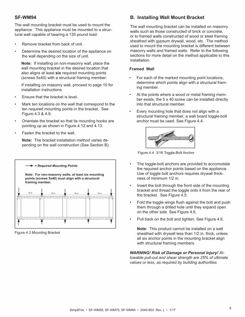
SF-WM94The wall mounting bracket must be used to mount the appliance. This appliance must be mounted to a struc-tural wall capable of bearing a 135 pound load.
• Remove bracket from back of unit. • Determine the desired location of the appliance on
the wall depending on the size of unit. Note: If installing on non-masonry wall, place the wall mounting bracket in the desired location that also aligns at least six required mounting points (screws 5x40) with a structural framing member.
If installing on masonry wall, proceed to page 10 for installation instructions.
• Ensure that the bracket is level.
• Mark ten locations on the wall that correspond to the ten required mounting points in the bracket. See Figure 4.3 & 4.9.
• Orientate the bracket so that its mounting hooks are pointing up as shown in Figure 4.12 and 4.13.
• Fasten the bracket to the wall. Note: The bracket installation method varies de-pending on the wall construction (See Section B).
Note: For non-masonry walls, at least six mounting points (screws 5x40) must align with a structural framing member.
SimpliFire • SF-WM58, SF-WM70, SF-WM94 • 2040-903 Rev. L • 1/17 10
Masonry Wall
• In the marked locations, drill 5/16 in. diameter x 2 in. deep holes. See Figure 4.7 (SF-WM58), Figure 4.8 (SF-WM70) or Figure 4.9 (SF-WM94).
• Insert the provided wall anchors into the holes.
• Gently tap the anchors with a hammer until they are flush with the wall surface.
• With mounting hooks pointed up, attach the bracket to the masonry anchors with 5 x 40 screws . See Figure 4.10 (SF-WM58), Figure 4.11 (SF-WM70) or Figure 4.12 (SF-WM94).
WARNING! Risk of Damage or Personal Injury! Do not use supplied masonry anchors on hollow walls, sheathed with wood, sheetrock, drywall or other materi-als.
Figure 4.6 Installing Anchors in Hollow Wall
Figure 4.5 Toggle Bolt Installation through Mounting Bracket
Wall
Masonry Anchors
Figure 4.7 (SF-WM58) Masonry Anchor Placement
Wall
Masonry Anchors
Figure 4.8 (SF-WM70) Masonry Anchor Placement
Wall
Masonry Anchors
Figure 4.9 (SF-WM94) Masonry Anchor Placement
Figure 4.10 (SF-WM58) Bracket Attachment
Mounting HooksPoint Up
Note: For non-masonry walls, at least two mounting points (screws 5x40) must align with structural framing member.
11SimpliFire • SF-WM58, SF-WM70, SF-WM94 • 2040-903 Rev. L • 1/17
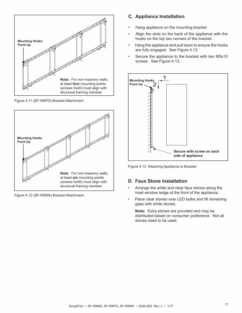
C. Appliance Installation
• Hang appliance on the mounting bracket. • Align the slots on the back of the appliance with the
hooks on the top two corners of the bracket. • Hang the appliance and pull down to ensure the hooks
are fully engaged. See Figure 4.13.• Secure the appliance to the bracket with two M5x10
screws. See Figure 4.13.
12
Secure with screw on each side of appliance.
Figure 4.13 Attaching Appliance to Bracket
Mounting HooksPoint Up
Figure 4.11 (SF-WM70) Bracket Attachment
Mounting HooksPoint Up
Note: For non-masonry walls, at least four mounting points (screws 5x40) must align with structural framing member.
Figure 4.12 (SF-WM94) Bracket Attachment
Mounting HooksPoint Up
Note: For non-masonry walls, at least six mounting points (screws 5x40) must align with structural framing member.
D. Faux Stone Installation• Arrange the white and clear faux stones along the
inset window ledge at the front of the appliance. • Place clear stones over LED bulbs and fill remaining
gaps with white stones. Note: Extra stones are provided and may be distributed based on consumer preference. Not all stones need to be used.
SimpliFire • SF-WM58, SF-WM70, SF-WM94 • 2040-903 Rev. L • 1/17 12
2
1Secure with Screw Here
Figure 4.14 Attaching Front to Appliance
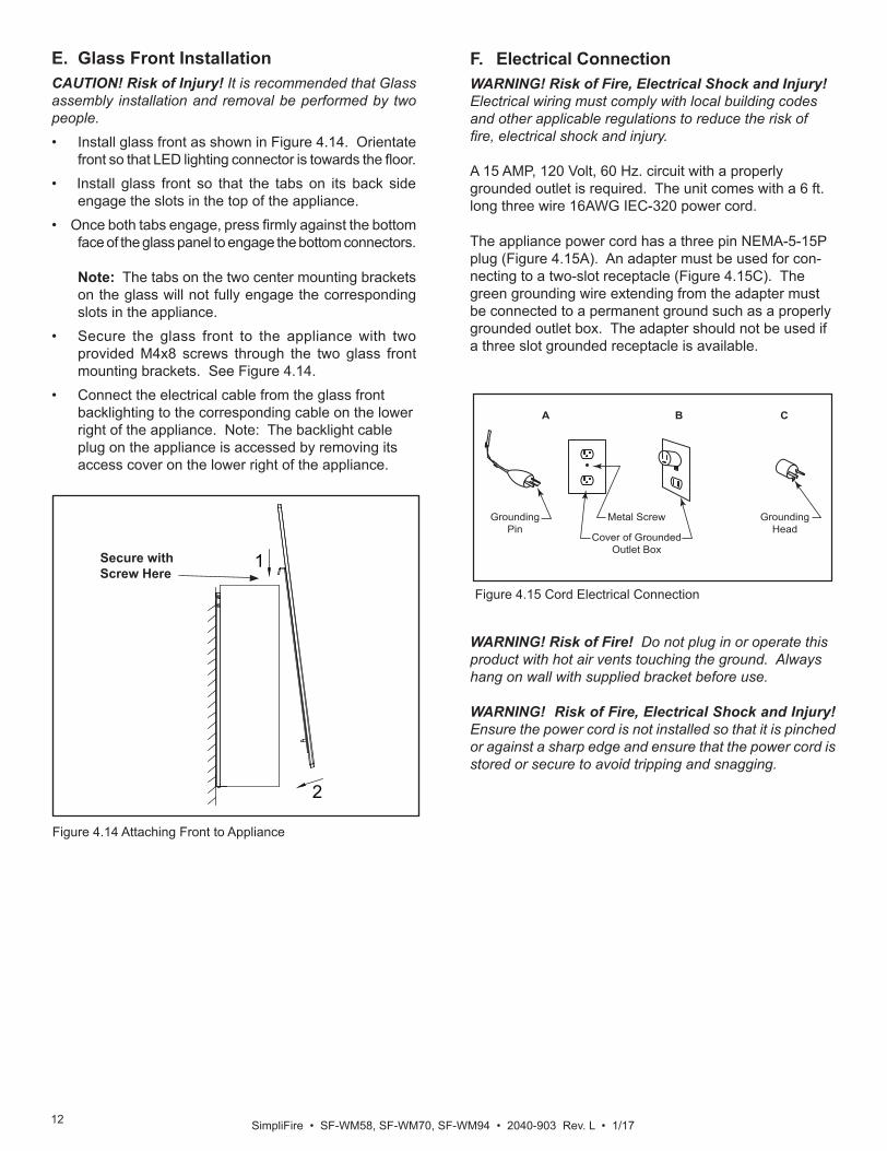
E. Glass Front InstallationCAUTION! Risk of Injury! It is recommended that Glass assembly installation and removal be performed by two people. • Install glass front as shown in Figure 4.14. Orientate
front so that LED lighting connector is towards the floor. • Install glass front so that the tabs on its back side
engage the slots in the top of the appliance. • Once both tabs engage, press firmly against the bottom
face of the glass panel to engage the bottom connectors. Note: The tabs on the two center mounting brackets on the glass will not fully engage the corresponding slots in the appliance.
• Secure the glass front to the appliance with two provided M4x8 screws through the two glass front mounting brackets. See Figure 4.14.
• Connect the electrical cable from the glass front backlighting to the corresponding cable on the lower right of the appliance. Note: The backlight cable plug on the appliance is accessed by removing its access cover on the lower right of the appliance.
F. Electrical ConnectionWARNING! Risk of Fire, Electrical Shock and Injury! Electrical wiring must comply with local building codes and other applicable regulations to reduce the risk of fire, electrical shock and injury.
A 15 AMP, 120 Volt, 60 Hz. circuit with a properly grounded outlet is required. The unit comes with a 6 ft. long three wire 16AWG IEC-320 power cord.
The appliance power cord has a three pin NEMA-5-15P plug (Figure 4.15A). An adapter must be used for con-necting to a two-slot receptacle (Figure 4.15C). The green grounding wire extending from the adapter must be connected to a permanent ground such as a properly grounded outlet box. The adapter should not be used if a three slot grounded receptacle is available.
GroundingPin
Metal Screw
Cover of GroundedOutlet Box
GroundingHead
CBA
Figure 4.15 Cord Electrical Connection
WARNING! Risk of Fire! Do not plug in or operate this product with hot air vents touching the ground. Always hang on wall with supplied bracket before use.
WARNING! Risk of Fire, Electrical Shock and Injury! Ensure the power cord is not installed so that it is pinched or against a sharp edge and ensure that the power cord is stored or secure to avoid tripping and snagging.
13SimpliFire • SF-WM58, SF-WM70, SF-WM94 • 2040-903 Rev. L • 1/17
CAUTION! The unit’s power cord must be connected to a properly grounded and protected 120V outlet. Always use ground fault protection where required by the electri-cal code.
WARNING! Risk of Fire, Electrical Shock, and Injury! Do not operate the unit if it is damaged or has malfunc-tioned. If you suspect the unit is damaged, call a qualified service technician to inspect and replace any part of the electrical system if necessary.
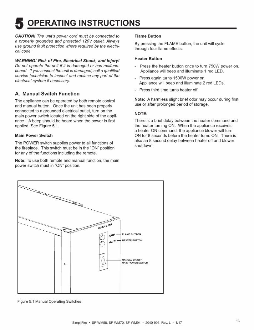
A. Manual Switch FunctionThe appliance can be operated by both remote control and manual button. Once the unit has been properly connected to a grounded electrical outlet, turn on the main power switch located on the right side of the appli-ance . A beep should be heard when the power is first applied. See Figure 5.1.
Main Power Switch
The POWER switch supplies power to all functions of the fireplace. This switch must be in the “ON” position for any of the functions including the remote.
Note: To use both remote and manual function, the main power switch must in “ON” position.
Flame Button
By pressing the FLAME button, the unit will cycle through four flame effects.
Heater Button
- Press the heater button once to turn 750W power on. Appliance will beep and illuminate 1 red LED.
- Press again turns 1500W power on. Appliance will beep and illuminate 2 red LEDs.
- Press third time turns heater off.
Note: A harmless slight brief odor may occur during first use or after prolonged period of storage.
NOTE:There is a brief delay between the heater command and the heater turning ON. When the appliance receives a heater ON command, the appliance blower will turn ON for 8 seconds before the heater turns ON. There is also an 8 second delay between heater off and blower shutdown.
Figure 5.1 Manual Operating Switches
5 OPERATING INSTRUCTIONS
FLAME BUTTON
HEATER BUTTON
MANUAL ON/OFF MAIN POWER SWITCH
SimpliFire • SF-WM58, SF-WM70, SF-WM94 • 2040-903 Rev. L • 1/17 14
B. Operating by Remote Control• The appliance Main Power Switch must be in the
“ON”position for the remote control to function.• Make sure batteries are properly installed in Remote
Control. - Battery requirements 2 x AAA batteries (included)
• The effective range of the remote is up to 13 ft.• The remote control must be within the 13 ft. range and
also be pointed directly at the face of the appliance. For best results, position the remote control within 45 degrees of the face of the appliance
C. Resetting Temperature Cutoff SwitchThe heater is protected with a safety device to prevent overheating. Should the heater overheat, an auto-matic cutoff will turn the heater OFF. It will not turn ON automatically without being reset. If it overheats for any reason, it can be reset by:1. Turn appliance to off2. Unplug unit and wait 5 minutes3. Plug in and turn on.
CAUTION: If appliance overheats repeatedly, discon-tinue use and call customer / technical support.
CAUTION: If you need to continuously reset the heater, unplug the appliance and contact customer / technical support.
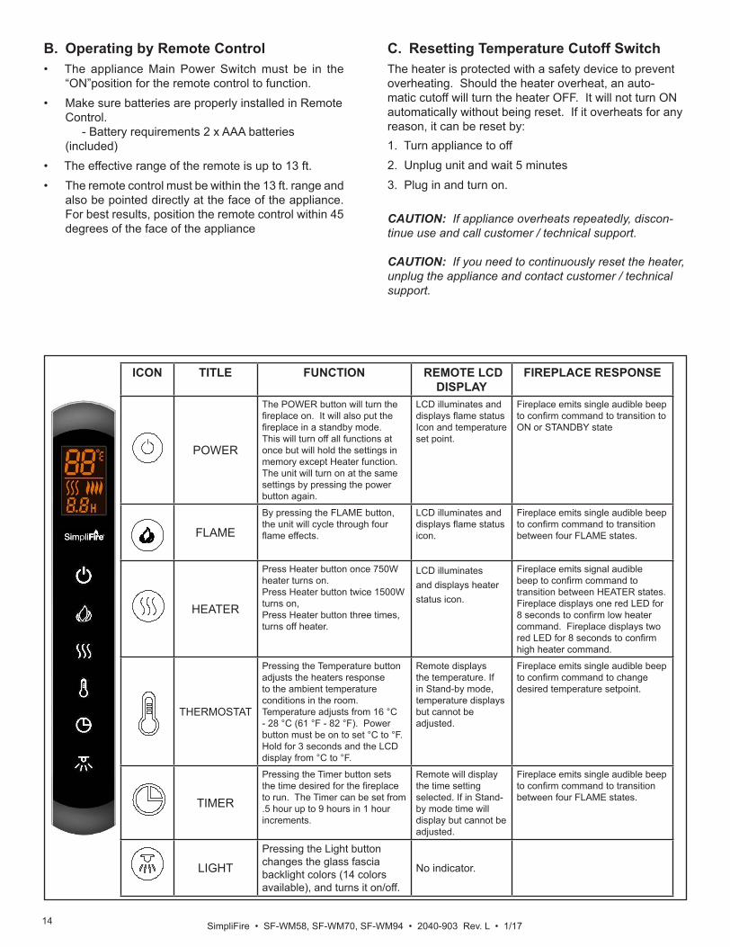
ICON TITLE FUNCTION REMOTE LCD DISPLAY
FIREPLACE RESPONSE
POWER
The POWER button will turn the fireplace on. It will also put the fireplace in a standby mode. This will turn off all functions at once but will hold the settings in memory except Heater function. The unit will turn on at the same settings by pressing the power button again.
LCD illuminates and displays flame status Icon and temperature set point.
Fireplace emits single audible beep to confirm command to transition to ON or STANDBY state
FLAME
By pressing the FLAME button, the unit will cycle through four flame effects.
LCD illuminates and displays flame status icon.
Fireplace emits single audible beep to confirm command to transition between four FLAME states.
HEATER
Press Heater button once 750W heater turns on. Press Heater button twice 1500W turns on,Press Heater button three times, turns off heater.
LCD illuminates and displays heater status icon.
Fireplace emits signal audible beep to confirm command to transition between HEATER states. Fireplace displays one red LED for 8 seconds to confirm low heater command. Fireplace displays two red LED for 8 seconds to confirm high heater command.
THERMOSTAT
Pressing the Temperature button adjusts the heaters response to the ambient temperature conditions in the room. Temperature adjusts from 16 °C - 28 °C (61 °F - 82 °F). Power button must be on to set °C to °F. Hold for 3 seconds and the LCD display from °C to °F.
Remote displays the temperature. If in Stand-by mode, temperature displays but cannot be adjusted.
Fireplace emits single audible beep to confirm command to change desired temperature setpoint.
TIMER
Pressing the Timer button sets the time desired for the fireplace to run. The Timer can be set from .5 hour up to 9 hours in 1 hour increments.
Remote will display the time setting selected. If in Stand-by mode time will display but cannot be adjusted.
Fireplace emits single audible beep to confirm command to transition between four FLAME states.
LIGHT
Pressing the Light button changes the glass fascia backlight colors (14 colors available), and turns it on/off.
No indicator.
15SimpliFire • SF-WM58, SF-WM70, SF-WM94 • 2040-903 Rev. L • 1/17
A. Maintenance WARNING! Risk of Shock! Always unplug the cord be-fore moving or servicing. Do not immerse appliance in water.• Always turn OFF the appliance and disconnect the
cord from the electrical outlet before cleaning your appliance.
• Light accumulated dust may be removed from the ap-pliance exterior with a soft cloth or vacuum cleaner.
• Wipe the exterior surfaces of the appliance occasion-ally with a slightly microfiber cloth using a solution of mild detergent and water. Dry thoroughly before op-erating the appliance.
CAUTION! Do not allow water to run into the interior of the appliance as this could create a fire or electric shock. Always unplug the cord before moving or servicing. • The fan motor is factory lubricated for life and will not
require further lubrication.• Store appliance in a clean dry place when not in use.
WARNING! Risk of Fire! To reduce risk of fire, do not store or use gasoline or any other flammable vapors or liquids in the vicinity of the appliance.
WARNING! Risk of Electrical Shock! Any other servic-ing needed must be performed by an authorized service representative. Do not attempt to service the unit your-self.
B. CleaningCleaning Glass
Dust particles can be removed by buffing lightly with a clean dry cloth. Fingerprints and other marks can be cleaned with a cloth dampened with a quality household glass cleaner. The glass should be completely dried with a lint free cloth or paper towel. Do not use abrasive clean-ers on glass surface. Do not spray liquids directly onto any surface.
Metal SurfaceDust particles can be removed by buffing lightly with a clean dry cloth. A damp cloth can be used to clean paint-ed surfaces. Do not use abrasive cleaners. Do not spray liquids directly on to any surface.
6 MAINTENANCE
C. Servicing
Except for installation and cleaning described in this man-ual, an authorized service representative should perform any other servicing.
SimpliFire • SF-WM58, SF-WM70, SF-WM94 • 2040-903 Rev. L • 1/17 16
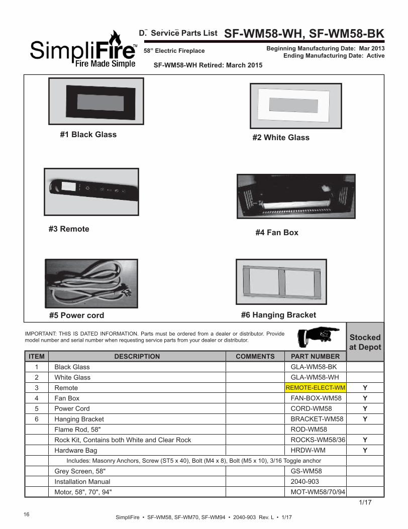
Service Parts SF-WM58-WH, SF-WM58-BKBeginning Manufacturing Date: Mar 2013
Ending Manufacturing Date: Active
IMPORTANT: THIS IS DATED INFORMATION. Parts must be ordered from a dealer or distributor. Provide model number and serial number when requesting service parts from your dealer or distributor. Stocked
at DepotITEM DESCRIPTION COMMENTS PART NUMBER
1 Black Glass GLA-WM58-BK2 White Glass GLA-WM58-WH3 Remote REMOTE-ELECT-WM Y4 Fan Box FAN-BOX-WM58 Y5 Power Cord CORD-WM58 Y6 Hanging Bracket BRACKET-WM58 Y
Flame Rod, 58" ROD-WM58Rock Kit, Contains both White and Clear Rock ROCKS-WM58/36 YHardware Bag HRDW-WM Y
Includes: Masonry Anchors, Screw (ST5 x 40), Bolt (M4 x 8), Bolt (M5 x 10), 3/16 Toggle anchor
Grey Screen, 58" GS-WM58Installation Manual 2040-903Motor, 58", 70", 94" MOT-WM58/70/94
1/17
58” Electric Fireplace
#1 Black Glass #2 White Glass
#3 Remote #4 Fan Box
#5 Power cord #6 Hanging Bracket
SF-WM58-WH Retired: March 2015
D. Service Parts List
17SimpliFire • SF-WM58, SF-WM70, SF-WM94 • 2040-903 Rev. L • 1/17
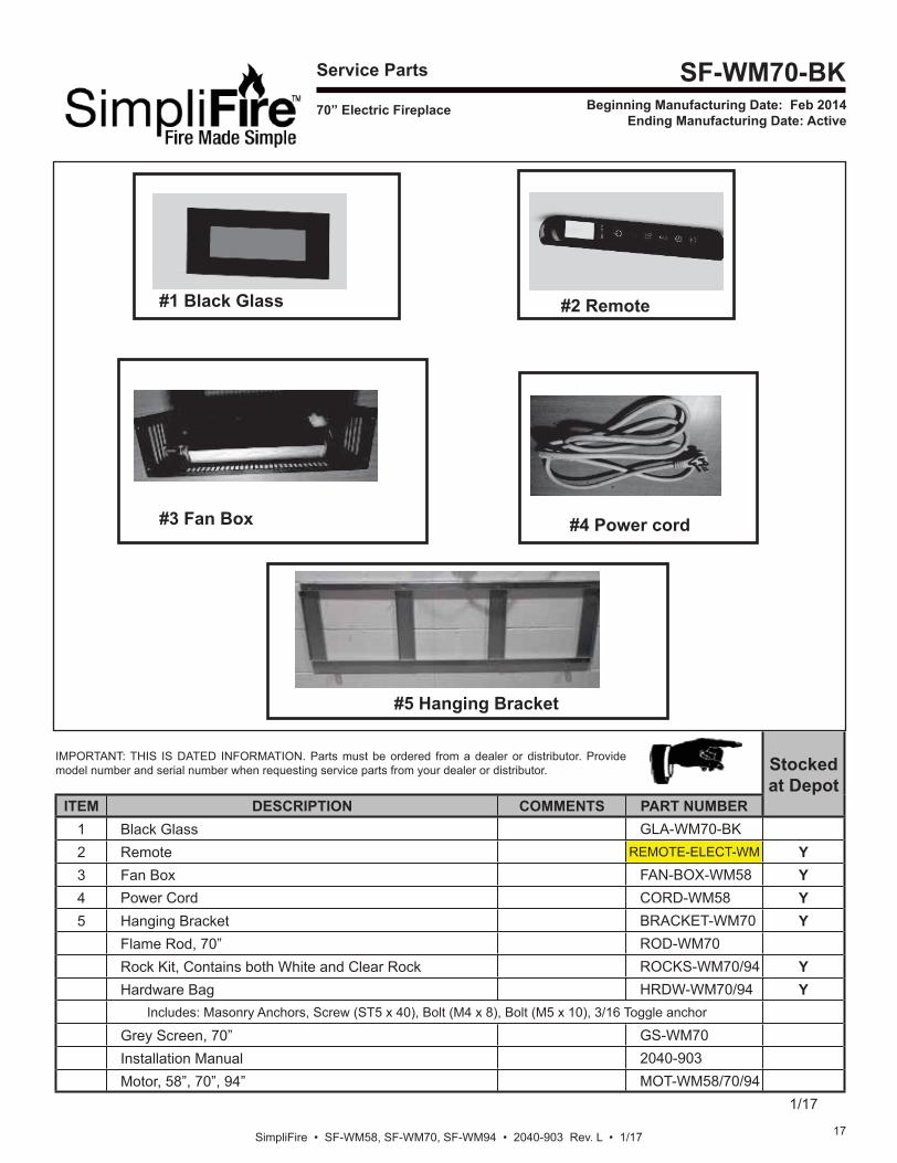
Service Parts SF-WM70-BKBeginning Manufacturing Date: Feb 2014
Ending Manufacturing Date: Active 70” Electric Fireplace
#1 Black Glass #2 Remote
#4 Power cord
#5 Hanging Bracket
IMPORTANT: THIS IS DATED INFORMATION. Parts must be ordered from a dealer or distributor. Provide model number and serial number when requesting service parts from your dealer or distributor. Stocked
at DepotITEM DESCRIPTION COMMENTS PART NUMBER
1 Black Glass GLA-WM70-BK2 Remote REMOTE-ELECT-WM Y3 Fan Box FAN-BOX-WM58 Y4 Power Cord CORD-WM58 Y5 Hanging Bracket BRACKET-WM70 Y
Flame Rod, 70” ROD-WM70Rock Kit, Contains both White and Clear Rock ROCKS-WM70/94 YHardware Bag HRDW-WM70/94 Y
Includes: Masonry Anchors, Screw (ST5 x 40), Bolt (M4 x 8), Bolt (M5 x 10), 3/16 Toggle anchor
Grey Screen, 70” GS-WM70Installation Manual 2040-903Motor, 58”, 70”, 94” MOT-WM58/70/94
1/17
#3 Fan Box
SimpliFire • SF-WM58, SF-WM70, SF-WM94 • 2040-903 Rev. L • 1/17 18
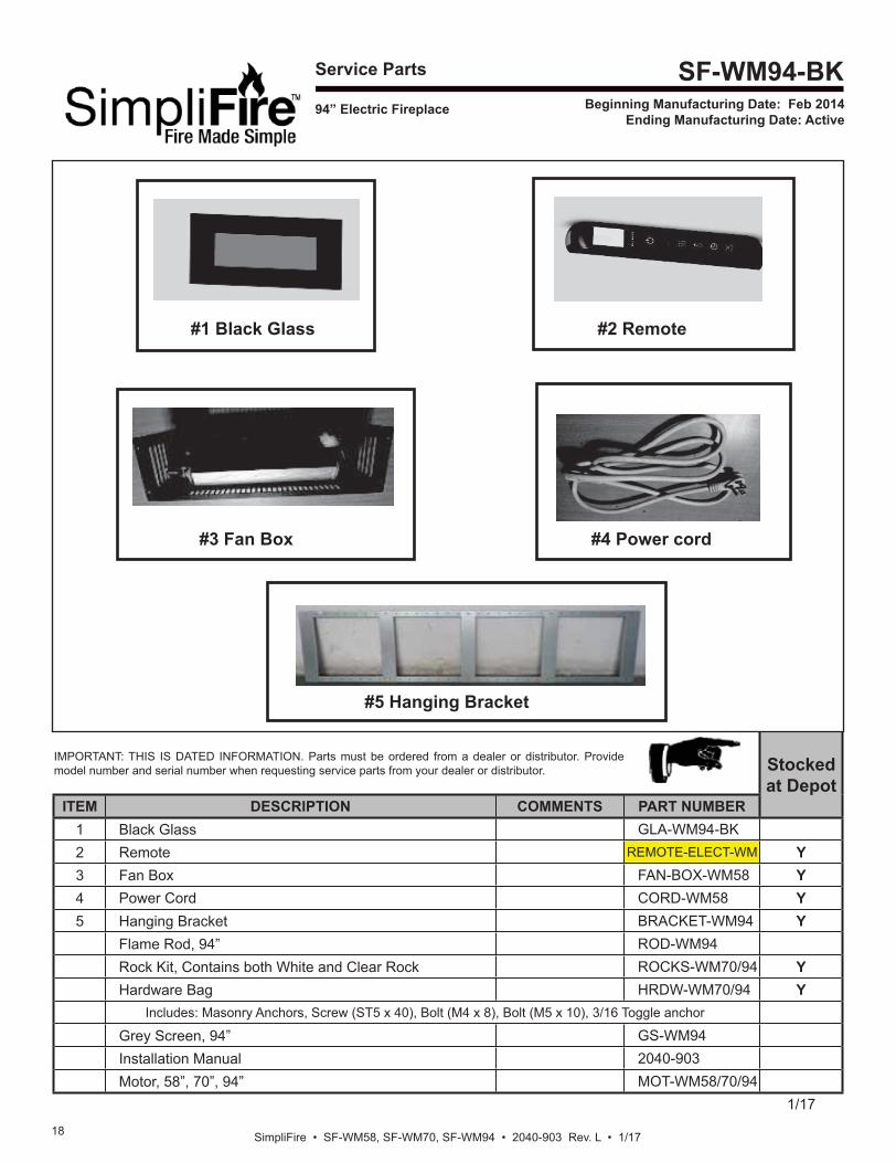
Service Parts SF-WM94-BKBeginning Manufacturing Date: Feb 2014
Ending Manufacturing Date: Active
IMPORTANT: THIS IS DATED INFORMATION. Parts must be ordered from a dealer or distributor. Provide model number and serial number when requesting service parts from your dealer or distributor. Stocked
at DepotITEM DESCRIPTION COMMENTS PART NUMBER
1 Black Glass GLA-WM94-BK2 Remote REMOTE-ELECT-WM Y3 Fan Box FAN-BOX-WM58 Y4 Power Cord CORD-WM58 Y5 Hanging Bracket BRACKET-WM94 Y
Flame Rod, 94” ROD-WM94Rock Kit, Contains both White and Clear Rock ROCKS-WM70/94 YHardware Bag HRDW-WM70/94 Y
Includes: Masonry Anchors, Screw (ST5 x 40), Bolt (M4 x 8), Bolt (M5 x 10), 3/16 Toggle anchor
Grey Screen, 94” GS-WM94Installation Manual 2040-903Motor, 58”, 70”, 94” MOT-WM58/70/94
1/17
94” Electric Fireplace
#1 Black Glass
#3 Fan Box
#2 Remote
#4 Power cord
#5 Hanging Bracket