wm2010 conference, march 7-11, 2010, phoenix, az
TRANSCRIPT
WM2010 Conference, March 7-11, 2010, Phoenix, AZ
Vitrification in a Cold Crucible Melter of HLLW Surrogate Solution: Behavior of Volatile Elements from Furnace to Off Gas Treatment - 10020
Eric Tronche, Jacques Lacombe, Alain Ledoux, Roger Boen, Christian LadiratCEA Marcoule, DEN/DTCD/SCDV
BP 17171, 30207 Bagnols-sur-Cèze cedex, FranceTel: 04.66.79.18.18, Fax: 04.66.79.17.65, Email:[email protected]
ABSTRACT
To solidify legacy high level liquid waste (HLLW) containing sulfates, the CEA (Commissariat à l’Energie Atomique is a French government-funded technological research organization) suggests the vitrification process in a Cold Crucible Induction Melter (CCIM). CEA and AREVA have designed an integrated platform based on the CCIM technology on a sufficient scale to be used for demonstration programs of the one-step process. A series of semi-industrial scale Vitrification tests has been carried in 2003 at Marcoule in southern France on simulated HLLW with high sulfur content. High throughputs were reached, with about 60 (L/h)/m2 of liquid flow rate directly feed on the molten glass surface heated to the temperature of 1250°C enabled by the use of a CCIM. The glass was produced at a throughput per unit area near 40 kg/h/m2.Sample collection taken during a sixty-hour test run has was made, including glass and liquids from the apparatus of the Off Gas Treatment System (OGTS). The elemental analyses of these samples enabled knowledge acquisition of the distribution of elements from the HLLW feed to the glass and the OGTS. The highly volatile elements such as sulfur and cesium are focussed onand a global flowsheet is established. Some indication of the performance of the off gas treatment apparatus can be obtained for each chemical element.
INTRODUCTION
A semi-industrial scale Vitrification process using à Cold Crucible Induction Melter (CCIM) hasbeen presented in 2009 at the Waste Management conference [1] to solidify HLLW surrogate solution containing sulfate.The HLLW are legacy wastes which contains large amounts of sodium, sulfur, iron and uranium.The data for this composition is given in a 1993 reference article [2] which this HLLW was to be treated by a Liquid-Fed Ceramic Melter process. The waste oxide loading of borosilicate glass is limited to 16 wt% to prevent yellow phase separation (consisting mainly of sodium sulfate). This yellow phase can be a problem because its density is low and it can float on the molten glass. Its electrical conductivity differs from that of the molten glass and can cause problems during the melter heating phase. Finally it can contribute to corrosion of the melter walls.The use of the CCIM technology can avoid the “yellow phase” issue according to the continuous process with a high throughput. The high specific power directly transferred by induction to the

WM2010 Conference, March 7-11, 2010, Phoenix, AZ
melt allows higher operating temperatures, thereby eliminating the yellow phase issue without any impact on the process equipment. Since all the process equipment is water cooled and protected by a solidified glass layer, the technology overcomes difficulties such as corrosion usually associated with high temperatures, and the melter has a virtually unlimited lifetime. Since there is no upper bound on the operating temperature, the CCIM can produce glass formulations with higher proportions of glass formers.In July 2003 a CCIM vitrification test took place at Marcoule in France on HLLW surrogate solution with a high sulfur content. CEA and AREVA have designed an integrated platform based on the CCIM technology on a sufficient scale to be used for demonstration programs using one-step process [3]. This paper describes the behavior of elements constituting the HLLW. How much goe’s in the glass and how can we manage them in the off gas treatment system to limit their contents in the secondary liquid waste. A overall flowsheet of the process is also presented.
Note that the context, process and apparatus of this test are specifics for these legacy wastes and different from those of a Nuclear Reactor Power Fuels reprocessing plant.
DESCRIPTION OF THE TEST FACILITY
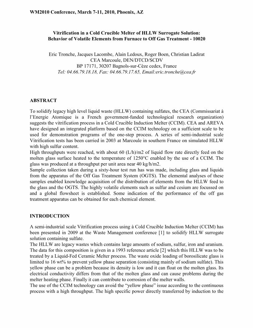
The demonstrations were performed by CEA/DEN/DTCD/SCDV using the existing Large Scale Integrated CCIM Pilot Facility at Marcoule, which was adapted to the specific requirements of the project.
Figure 1. Overall view of the test facility.

WM2010 Conference, March 7-11, 2010, Phoenix, AZ
1: 650 mm diameter CCIM behind its protection barriers2: canister filling station equipped with a balance to measure the poured glass mass3: glass frit tanks above the solid gravity-feed system4: high-frequency generator5: water cooled supply system 6: (a) the liquid dust scrubber system; (b) the unused solid dust scrubber system7: condenser8: washing column9: extractor
The demonstration facility is self-contained and comprises all the systems and components necessary to perform a large-scale continuous one-week demonstration run: a melter feed system, a 650 mm diameter CCIM, a glass pouring station, a canister filling station, a complete off-gas treatment system, and related auxiliary equipment, including the control system. The facility is installed on four levels covering 160 m2 at ground level.
Vitrification system
The development version melter used in 2003 for the demonstration was a 650 mm diameter cold-crucible induction melter not representative of the robust design that has been qualified for radioactive operation in the La Hague vitrification plant today.The melter was powered by a 600 kW high-frequency generator delivering power to a copper inductor wrapped around the melter sectored vertical wall. The power supply line to the inductor included a high-frequency high-voltage line and an impedance matching device to adapt the generator to the load in the crucible. The tuning of this impedance adaptor is based on modeling and calculations performed prior to the demonstration, which took into account the physical properties of the glass versus temperature (thermal conductivity, electrical conductivity, and viscosity). The facility included a cooling loop with separate branches for the melter, the dome and for ancillary equipment, as well as an emergency cooling system for the melter. Each branch was individually equipped with temperature and flow rate measuring devices to gather data inputs necessary for the thermal balance.The melter was equipped with a water-cooled retractable mechanical stirrer and its drive mechanism, a cooled bubbling tube to assist melt homogenization, and a pouring device consisting of two cooled slide valves and their actuators. The melter was also equipped with two thermocouples for measuring the melt temperature from the bottom.
Melter feed system
The existing liquid feed system of the demonstration platform was used for this demonstration. This melter feed system included a preparation and feed tank located inside the building equipped with a mechanical stirrer designed with three levels of blades: a smaller blade below two levels of full-size blades. The useful volume of the feed tank was 8 m3. The tank was also equipped with dip tube bubbler-based level and density measurements, and a thermocouple for temperature measurement. The built-in stirring capability of the feeding tank was supplemented by a high flow rate (> 5 m3/h) recirculation loop extracting the liquid from the bottom of the tank

WM2010 Conference, March 7-11, 2010, Phoenix, AZ
and reinjecting it at the top. Sampling was also possible in this loop, directly below the bottom of the tank. The solution was pumped from the recirculation loop and metered before it was added to the CCIM. Glass frit stored in a tank was transferred by a worm screw and metered by the screw rotation speed. The glass frit dropped into an airlock to ensure frit supply as well as depressurized gas confinement in the CCIM.
Glass pouring enclosure and canister filling station
During glass pouring, the receiving canister was located inside an insulated enclosure equipped with weighing scales. The canisters were made of ordinary carbon steel and could receive approximately 400 kg of glass. Glass sampling could be performed below the outlet of the CCIM pouring system by grabbing small quantities of glass in steel or cast iron pans.
Off-gas treatment system (OGTS)
The melter off-gas outlet is directly connected to the liquid dust scrubber. The dust scrubber is a heated vessel topped with a column in which the off-gas is contacted with a counter-current flow of liquid circulated from the vessel in order to trap the entrained particles. The dust scrubber is heated to prevent internal condensation. In normal operation the dust scrubber is continuously fedwith a small flow of fresh water, and the excess liquid, loaded with the collected material, is recycled to the CCIM with the main feed. This represents around 10% of the feed. The off-gas then flows through a condenser where the moisture is condensed. The condensates are collected in a specific cooled tank. Downstream of the condenser, the off-gas flows through a washing column where it is contacted with a caustic solution to remove the acidic gases (NOx and others). A centrifuge extractor removes the off-gas and provides for a slightly negative pressure throughout the system to the melter. The three components can be sampled to confirm the estimated distribution of entrained and volatilized species. Each is equipped with level and temperature measuring instruments. Pressure is measured before and after each equipment item.
Control and monitoring
The Large Scale Integrated CCIM Pilot Facility is fully instrumented and operated remotely using a Programmable Logic Controller and a Digital Control System with a multi-screen display. All the process parameters can be monitored, time-stamped, and recorded to provide historical trend information. The control system includes warning thresholds on each critical measurement and automatic shut-down sequence to assure safe operation of the system.
CHARACTERISTICS OF HLLW SURROGATE SOLUTION, GLASS FRIT AND GLASS
The borosilicate glass formulation and a frit are described in reference [2] for the LFCM technology. These compositions are also compatible with processing in the CCIM. According to reference [2], at 1150°C the glass viscosity is 57 dPa·s and the electrical resistivity is equal to 5.3 ohm·cm. These physical properties are suitable for satisfactory operation in our CCIM.
WM2010 Conference, March 7-11, 2010, Phoenix, AZ
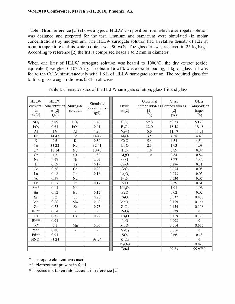
Table I (from reference [2]) shows a typical HLLW composition from which a surrogate solution was designed and prepared for the test. Uranium and samarium were simulated (in molar concentrations) by neodymium. The HLLW surrogate solution had a relative density of 1.22 at room temperature and its water content was 90 wt%. The glass frit was received in 25 kg bags. According to reference [2] the frit is comprised beads 1 to 2 mm in diameter.
When one liter of HLLW surrogate solution was heated to 1000°C, the dry extract (oxide equivalent) weighed 0.10325 kg. To obtain 16 wt% waste oxide loading, 1 kg of glass frit was fed to the CCIM simultaneously with 1.8 L of HLLW surrogate solution. The required glass frit to final glass weight ratio was 0.84 in all cases.
Table I: Characteristics of the HLLW surrogate solution, glass frit and glass
HLLW element/
ion as [2]
HLLW concentration
as [2] (g/l)
Surrogate solution
Simulated concentration
(g/l)
Oxideas [2]
Glass Frit composition as
[2](%)
Glass Composition as
[2](%)
Glass Composition
target(%)
SO4 5.09 SO4 3.40 SiO2 59.8 50.23 50.23PO4 0.61 PO4 0.61 B2O3 22.0 18.48 18.48Al 4.9 Al 4.90 Na2O 5.0 11.19 11.21Fe 14.47 Fe 14.47 Al2O3 3.5 4.38 4.43K 0.5 K 0.50 CaO 5.4 4.54 4.54Na 33.22 Na 32.41 Li2O 2.3 1.93 1.93U* 16.14 Nd 10.48 TiO2 1.0 0.89 0.89Cr 1.3 Cr 1.30 MgO 1.0 0.84 0.84Ni 2.97 Ni 2.97 Fe2O3 3.23 3.32Ti 0.19 Ti 0.19 Cr2O3 0.296 0.31Ce 0.28 Ce 0.28 CeO2 0.054 0.05La 0.18 La 0.18 La2O3 0.033 0.03Nd 0.59 Nd P2O3 0.030 0.07Pr 0.17 Pr 0.17 NiO 0.59 0.61
Sm* 0.11 Nd Nd2O3 1.91 1.96Ba 0.12 Ba 0.12 BaO 0.02 0.02Sr 0.2 Sr 0.20 SrO 0.037 0.038
Mo 0.68 Mo 0.68 MoO3 0.159 0.164Zr 0.73 Zr 0.73 ZrO2 0.154 0.158
Ru** 0.14 - - RuO2 0.029 0Cs 0.72 Cs 0.72 Cs2O 0.119 0.123
Rh** 0.01 - - PdO 0.003 0Tc* 0.1 Mn 0.06 MnO2 0.014 0.015Y** 0.08 - - Y2O3 0.016 0Pd** 0.01 - - SO3 0.66 0.45HNO3 93.24 93.24 K2O# 0
Pr2O3# 0.097Total 99.83 99.97%
*: surrogate element was used **: element not present in feed#: species not taken into account in reference [2]
WM2010 Conference, March 7-11, 2010, Phoenix, AZ
The 0.45% content of SO3 equivalent in the glass was relatively high. Incorporating this quantity in the glass formulation depends on the waste oxide loading, temperature (°C), throughput (kg/h) and stirring. The waste oxide loading of borosilicate glass is limited to 16wt% to prevent yellow phase separation consisting mainly of sodium sulfate (Na2SO4).In a previous test run some yellow phase was obtained at temperatures near 1150°C. Samples of this solidified phase at room temperature were examined by SEM/EDS. It reveals sodium sulfate cristals. The yellow color is probably due to chromium oxide (Cr2O3) but it can also contain molybdenum, which has the same peak as sulfur. This yellow phase is a liquid at 1150°C; its density is low and it can float on the molten glass. Its electrical conductivity differs from that of the molten glass and can allow an electric current loop to form all around the CCIM sectors and destroy them during the melter heating phase. As this yellow phase can contribute to the corrosion of the melter walls, its liquid form is prohibited in an operating CCIM.One of the major advantages identified for the CCIM is its ability to operate at high temperature, which allows the transformation of the liquid yellow phase to the gaseous form when the temperature reaches about 1250°C.
DEMONSTRATION RUN
The demonstration run was performed in a single step by feeding the liquid directly to the cold crucible without any prior solution treatment. In 2003 the CCIM at Marcoule evaporated 22.5 liters of liquid per hour consisting of 2.5 L/h of recycled liquid and 20 L/h of HLLW surrogate solution. The reference [1] describes in details:
CCIM startup CCIM feed characteristics CCIM process operating characteristics CCIM electrical parameters CCIM glass weight management Glass characterizations and mass balance
The liquid and frit feeds are not interrupted during the pours. This operating mode is allowed because formers (frit or solution ashes)were not found in the solidified glass. This operating mode increased the overall CCIM production rate.The glass bath temperature was monitored by the generator power. The target temperature was 1250°C. One thermocouple was used for regulation and its signal was monitored by a backup thermocouple. The CCIM atmosphere was satisfactorily maintained at 300 Pa below atmospheric pressure throughout the demonstration run. No overpressure occurred during the run.For these legacy wastes containing sulfate, the one-step demonstration run carried out on HLLW surrogate solution was successfully completed. With a HLLW surrogate solution feed rate of 20 L/h to the CCIM, the liquid feed flow was about 60 (L/h)/m2 at 1250°C.
Glass production
The glass was produced at a rate of 12.9 kg/h, corresponding to a throughput per unit area of 38.8 kg/h/m2. During this run, 1114 liters of HLLW surrogate solution was treated in 62 hours.

WM2010 Conference, March 7-11, 2010, Phoenix, AZ
The glass was synthesized in the CCIM in 100 kg batches on a glass heel. The glass was poured in quantities of about 100 kg. Seven melts were performed, for a total of 730 kg of glass.The theoretical waste oxide loading was very near the 16 wt% target. They were specific to each melt but the glass composition depended on the previous glass holdup composition in the CCIM before each melt.
Samples of the glass poured were taken in the canister. The chemical analysis results for the interesting glass constituents are shown in figure 2.
Glass composition for interesting elements
0%
1%
2%
3%
4%
5%
1 2 3 4 5 6 7
pours
wt(
%)
[Al;
Nd
; S
; C
s]
0%
12%
24%
36%
48%
60%
wt(
%)
[Si;
Na
;B]
Ref_Al2O3
Ref_Cs2O
Ref_Nd2O3
Ref_SO3
Ref_SiO2
Ref_Na2O
Ref_B2O3
Figure 2: Glass composition analysis for the interesting elements
The concentrations of the main borosilicate glass constituents (SiO2, B2O3, Na2O, Al2O3) represented more than 80 wt% of the total mass of the glass. The SO3 content is very important for the process behavior and also the Cs2O and Nd2O3 contents representatives of the radio-active components. The resulting glass compositions were stable for all seven melts and confirmed that the glass target composition (Table I) was obtained.
The SO3 content in the glass continuously increased during the demonstration run. This increasing shows that the conditions of saturation are not reached after more than 65 hours test run. Beside kinetic considerations the bath temperature goes against SO3 incorporation. However, no liquid yellow phase was observed at any time during the test. The final SO3 content was 0.37 wt% in the glass for a target value of 0.45 wt%. All the solidified glass samples obtained were smooth, bright with neither crystalline inclusions nor solidified yellow phase.

WM2010 Conference, March 7-11, 2010, Phoenix, AZ
They were black, with a thin yellow-green layer in some cases. All these technological glasses can be considered excellent based on macroscopic observations.
OFF GAS TREATMENT SYSTEM ELEMENT’S BEHAVIOR
Description of the operating process with the Secondary Liquid Waste from the off gas treatment system
Sample collection taken during a sixty-hour test run has been made, including glass and liquids from the apparatus of the Off Gas Treatment System (OGTS). The elemental analyses of these samples allowed achieving the knowledge of the repartition of elements from the HLLW feed to the glass and the OGTS. The high volatile elements as sulfur and cesium are particularly studied.
Dust scrubber Condenser Washing Column Extractor
PF Liquid feeding
Glass frit
CCM
Glass
2,5 /h
20 /h
V
10,8 kg/h
1250°C
12,9 kg/h
Glass loading factor =16%
=> 2,1 kg/h
GF
H2O
NaOH
C L
R
6 /h
26 /h 5 /h
F
Dust scrubber Condenser Washing Column Extractor
PF Liquid feeding
Glass frit
CCM
Glass
2,5 /h
20 /h
V
10,8 kg/h
1250°C
12,9 kg/h
Glass loading factor =16%
=> 2,1 kg/h
GF
H2O
NaOH
C L
R
6 /h
26 /h 5 /h
FPF Liquid feeding
Glass frit
CCM
Glass
2,5 /h
20 /h
V
10,8 kg/h
1250°C
12,9 kg/h
Glass loading factor =16%
=> 2,1 kg/h
GF
H2O
NaOH
C L
R
6 /h
26 /h 5 /h
F
Figure 3: Schematic flow-sheet of the Vitrification Process including the OGTS
For more than 50 hours the mean HLLW solution feed rate was 20 L/h. In the particle separator the mean water flow rate of 6 L/h maintained a constant liquid level at the bottom of the column to compensate both for the losses due to recycling back to the CCIM (R) and to evaporation by heating of the liquid to the boiling point, and also prevented overflowing from the particle separator. This high-temperature wet scrubber trapped most of the volatile elements which were then recycled to the melter, thereby guaranteeing the resulting glass composition and minimizing the quantities of elements released in the secondary effluents.The liquid supplied to the furnace and scrubber was ultimately evaporated and recovered in the water-cooled condenser to obtain the initial feed flow rates, 26 L/h (C). In reality, due to recombination of nitrous fumes and nitric acid, the densities of the process solutions differed and their volumes cannot simply be summed together. However, the volume balance between the
WM2010 Conference, March 7-11, 2010, Phoenix, AZ
inputs and the condensate output was the same within less than 3%, and the convergence is thus satisfactory.The noncondensable gases at the condenser outlet may still have contained nitrous fumes that were trapped by scrubbing with a soda solution at a rate of about 5 L/h and recovered at the bottom of the column via a constant-level overflow; the scrubbing column outlet flow rate is designated L.
Instantaneous rate as criterion of the study
Effluent samples from the particle separator, condenser and scrubbing column were taken at regular intervals throughout the test and at the end of the glass synthesis. The elemental compositions were determined by analysis to estimate the release of each element from the feed solution into the off-gas treatment. The selected criterion was the “instantaneous rate” for each device. We therefore calculated the recycle rate, the condenser rate and the scrubber rate. Each of these rates represents the ratio between the mass flow at the device output and the mass flow of feed solution at a given instant t. Hence the following equations:
Fi
Ri
t xF
xRRatecycled
*
*Re
Fi
Ci
t xF
xCRateCondenser
*
*
Fi
Li
t xF
xLRateWashed
*
*
The instantaneous rates correspond to a snapshot of the dynamic process. At equilibrium the rates are representative of the actual process material balance.Each chemical element has its own properties and behavior and must be examined separately. The following study concerns the particular behavior of three elements: sulfur, cesium and neodymium. In the graphs the instantaneous rates are plotted on the Y-axis and the number of hours of solution feed from the initial “zero” point on the X-axis.
Sulfur behavior in the CCIM and in the OGTS
Sulfur was examined in particular because it is the main problem source in glass melters operating at about 1150°C. Sodium sulfate is a conductive liquid at this temperature and is highly aggressive toward the furnace structural materials. It also concentrates highly radioactive elements such as cesium, and has no confinement properties. This compound must therefore not be present in the glass packages produced, and sulfur loading is acceptable only at microscopic scale in the amorphous glass. The cold crucible melter avoids the problem of sodium sulfate by synthesizing the glass above 1200°C, which is the boiling or decomposition temperature of this compound. By operating the cold crucible melter at 1250°C this element is deliberately shunted into the off-gas stream with no impact on the final material quality. At the same time, the presence of cold reactants above the melt allows the glass to “digest” sulfur, which in the form of

WM2010 Conference, March 7-11, 2010, Phoenix, AZ
SO3 ultimately accounts for about 0.4 wt% of the glass formed. Large quantities of sulfur are therefore found in the off-gas treatment system.
Sulfate behavior in gaz treatment Instantaneous Rate.
0%
5%
10%
15%
20%
25%
30%
35%
40%
45%
50%
55%
60%
0 10 20 30 40 50 60 70Tops (h)
Ra
te (
%)
Sulfate - Recycled Rate (%)
Sulfate - Condenser Rate (%)
Sulfate - Washed Rate (%)
Figure 4: Sulfate behavior in the Off Gas Treatment System
This graph shows the results obtained for sulfates in the system. The blue curve shows that the dust scrubber operating at the boiling point does not trap much of the sulfur. The recycle rate to the cold crucible melter at equilibrium represents about 10% of the total amount contained in the feed solution.In the off-gas treatment system the steam condenser is the first device operating at low temperature, which is necessary to trap gaseous sulfur oxides. Most of the sulfur is thus found in the condenser effluents at equilibrium: about 35 wt% of the sulfur initially present in the HLLW. Sulfur recombines in aqueous media to form sulfuric acid, resulting in a highly acidic effluent. This sulfur equilibrium is reached after about 30 hours of operation. During the first few operating hours the quantity of sulfur in the condensates is much higher, which means it is poorly incorporated in the glass. This is partially attributable to the absence of a blanket over the melt during the first ten hours, but which is subsequently formed for the maximum HLLW capacity considered here (20 L/h).At equilibrium, the secondary effluents formed by the condensates and liquid scrubbing effluents respectively entrain about 35% and 5% of the sulfur initially present in the HLLW. Their fate is not discussed here, but in the active process they would be sent to an evaporator if their activity warranted this option.

WM2010 Conference, March 7-11, 2010, Phoenix, AZ
Cesium behavior in the OGTS
Cesium behavior in gaz treatment Instantaneous Rate.
0%
1%
2%
3%
4%
5%
6%
7%
8%
9%
10%
11%
12%
13%
14%
15%
0 10 20 30 40 50 60 70Tops (h)
Rat
e (
%)
Cs - Recycled Rate (%)
Cs - Condenser Rate (%)
Cs - Washed Rate (%)
Cs - Washed Rate (%)
Detection limit values
Figure 5: Cesium behavior in the Off Gas Treatment System
Cesium is of particular importance by virtue of its radioactive properties. It is less volatile than sulfur and the Y-axis scale of this graph is smaller by a factor of 4 than for sulfur. About 5% of the cesium is recycled to the cold crucible melter at equilibrium, as this element is partially recovered in the boiling particle separator effluents. The condensates, however, contained another 5% of cesium that passed through the particle separator. A fraction of this cesium may therefore have been in gaseous form that was only trapped at the low temperatures of the condenser.Cesium was detected with certainty in the effluents from the caustic scrubbing column only in the samples taken at 12 and 20 hours. Sodium was subsequently determined by analysis after dilution, but at levels corresponding to the detection limits for this element in the strong soda effluent. The results are nevertheless plotted in the graph. Only the results of the sample taken after 20 operating hours (near the equilibrium conditions obtained after about 30 hours) can provide a scientifically robust result: the scrubbing column effluents contain about one-fourth the amount present in the condensates.

WM2010 Conference, March 7-11, 2010, Phoenix, AZ
Neodymium behavior in the OGTS
Neodym behavior in gaz treatment Instantaneous Rate.
0,0%
0,5%
1,0%
1,5%
2,0%
2,5%
3,0%
3,5%
4,0%
0 10 20 30 40 50 60 70Tops (h)
Ra
te (
%)
Neodym - Recycled Rate (%)
Neodym - Condenser Rate (%)
Neodym - Washed Rate (%)
Figure 6: Neodymium behavior in the Off Gas Treatment System
In the glass production range, neodymium exhibits chemical properties comparable to those of uranium. In an inactive facility such as our test bed, neodymium is therefore used to simulate uranium and it is assumed that the behavior of neodymium in the off-gas system is comparable to that of uranium. In the actual HLLW effluent examined (refer to Table I) the quantity of uranium is relatively large, and is also simulated by neodymium. We have therefore specifically included the graph illustrating the distribution of this element in the off-gas system.The first particularity of this graph is the order of magnitude of the Y-axis, which is even smaller than for cesium. Neodymium is therefore not considered a volatile element. It is trapped by the particle separator, probably in the form of particulates entrained in the vapors produced by the boiling HLLW solution on the molten glass. It is continuously recycled to the cold crucible melter at a rate of 1.5%. The condensates are the only secondary effluents in which neodymium was found at a concentration of about 0.5% at equilibrium.
REPARTITION FLOWSHEET OF ELEMENTS FROM THE HLLW FEED TO THE GLASS AND THE OFF GAS TREATMENT SYSTEM
An elemental flowsheet was established at the end of the test to summarize these results. Sodium and strontium were included in this overview in addition to the three elements described above.
WM2010 Conference, March 7-11, 2010, Phoenix, AZ
PF Liquid feeding
Glass frit
CFE
Glass
Total = V+C+L+ C L
R
R+C+L+
V
NaOH
Dust scrubber Condenser Washing Column
Extractor
GF
1250°C
F
S 100%Cs 100%Sr 100%Nd 100%Na 64,5%
S 9%Cs 4%Sr 3%Nd 0,9%Na 1,1%
Values issued from analysis Calculated Values
Na 35,5%
S 53%Cs 92%Sr 100%Nd 98%Na 97%
S 32%Cs 4%Sr 0,5%Nd 0,3%Na 1,2%
S 3,9%Cs XXXSr 0,00%Nd 0,00%Na XXX
S 89%Cs 96%Sr 101%Nd 99%Na 98%
S 45%Cs 8%Sr 3%Nd 1%Na 2%
PF Liquid feeding
Glass frit
CFE
Glass
Total = V+C+L+ C L
R
R+C+L+
V
NaOHNaOH
Dust scrubber Condenser Washing Column
Extractor
GF
1250°C
F
S 100%Cs 100%Sr 100%Nd 100%Na 64,5%
S 9%Cs 4%Sr 3%Nd 0,9%Na 1,1%
Values issued from analysis Calculated Values
Na 35,5%
S 53%Cs 92%Sr 100%Nd 98%Na 97%
S 32%Cs 4%Sr 0,5%Nd 0,3%Na 1,2%
S 3,9%Cs XXXSr 0,00%Nd 0,00%Na XXX
S 89%Cs 96%Sr 101%Nd 99%Na 98%
S 45%Cs 8%Sr 3%Nd 1%Na 2%
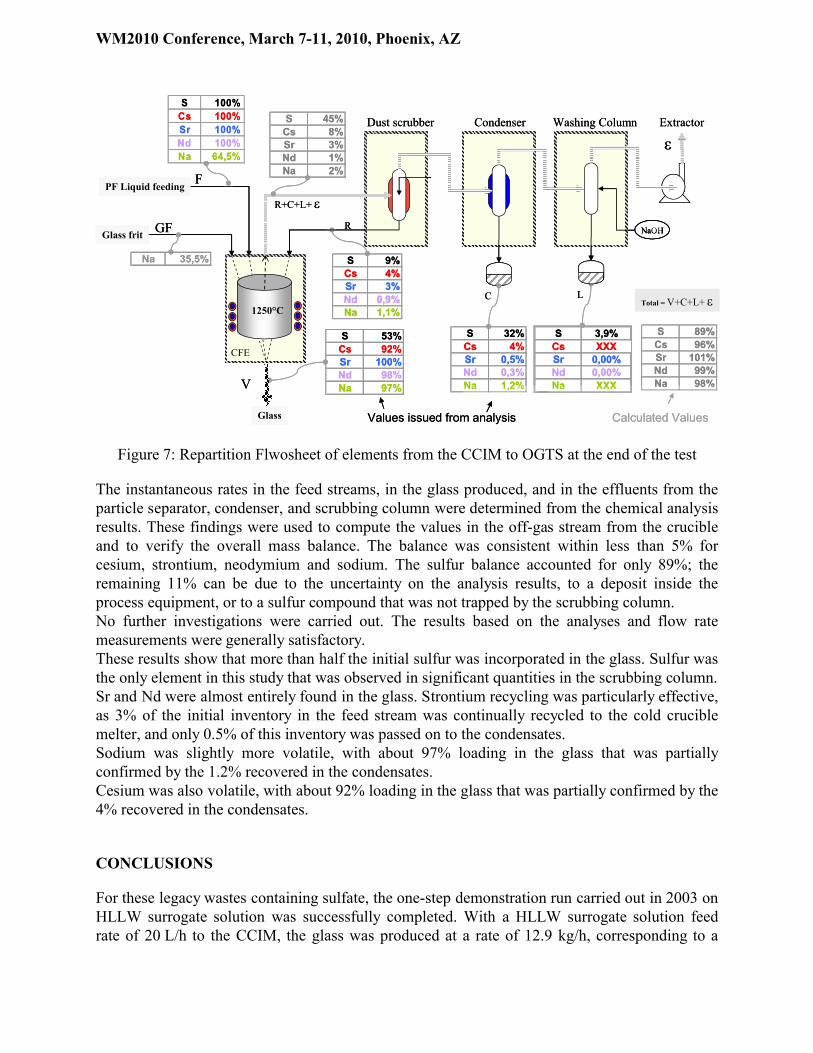
Figure 7: Repartition Flwosheet of elements from the CCIM to OGTS at the end of the test
The instantaneous rates in the feed streams, in the glass produced, and in the effluents from the particle separator, condenser, and scrubbing column were determined from the chemical analysis results. These findings were used to compute the values in the off-gas stream from the crucible and to verify the overall mass balance. The balance was consistent within less than 5% for cesium, strontium, neodymium and sodium. The sulfur balance accounted for only 89%; the remaining 11% can be due to the uncertainty on the analysis results, to a deposit inside the process equipment, or to a sulfur compound that was not trapped by the scrubbing column.No further investigations were carried out. The results based on the analyses and flow rate measurements were generally satisfactory.These results show that more than half the initial sulfur was incorporated in the glass. Sulfur was the only element in this study that was observed in significant quantities in the scrubbing column.Sr and Nd were almost entirely found in the glass. Strontium recycling was particularly effective, as 3% of the initial inventory in the feed stream was continually recycled to the cold crucible melter, and only 0.5% of this inventory was passed on to the condensates.Sodium was slightly more volatile, with about 97% loading in the glass that was partially confirmed by the 1.2% recovered in the condensates.Cesium was also volatile, with about 92% loading in the glass that was partially confirmed by the 4% recovered in the condensates.
CONCLUSIONS
For these legacy wastes containing sulfate, the one-step demonstration run carried out in 2003 on HLLW surrogate solution was successfully completed. With a HLLW surrogate solution feed rate of 20 L/h to the CCIM, the glass was produced at a rate of 12.9 kg/h, corresponding to a

WM2010 Conference, March 7-11, 2010, Phoenix, AZ
throughput per unit area of 38.8 kg/h/m2. During this run, 1114 liters of HLLW surrogate solution was treated and 730 kg of glass were fabricated in 62 hours. The mass balance was verified within better than 5% for cesium, strontium, neodymium and sodium. The result for sulfur was more difficult to establish, and the mass balance was verified within only about 10%. The results show that more than half the initial sulfur was incorporated in the glass. Sulfur was the only element in this study that was observed in significant quantities in the scrubbing column.After sulfur, the most volatile element was cesium. The use of a wet scrubber ensured continuous recycling of half the quantity entering the off-gas stream from the cold crucible melter. The quantity entering the off-gas represented about 8% of the initial inventory in the feed solution. The 4% not recycled to the melter were entirely recovered in the condensates. In the cold crucible vitrification process operating at equilibrium no cesium was detected in the scrubbing column.Sr and Nd were almost entirely found in the glass. The use of a wet scrubber was particularly effective for strontium, as 3% of the initial inventory in the feed stream was continuously recycled to the cold crucible melter, and only 0.5% of the inventory reached the condensates.Sodium was slightly more volatile, with about 97% loading in the glass that was partially confirmed by the 1.2% recovered in the condensates.The results based on the analyses and flow rate measurements were generally satisfactory.
This process can’t be applied with the same process parameters for HLLW coming from the treatment of Nuclear Reactor Power Fuels.
REFERENCES
[1] E. Tronche, J. Lacombe, A. Ledoux, R. Boen, C. Ladirat. “Vitrification of HLLW Surrogate Solutions Containing Sulfate in a Direct-Induction Cold Crucible Melter”. Proceedings of the Waste Management 2009 Symposium WM’10 Conference, March 1-7, 2009, AZ, Phoenix, USA (2009)
[2] Sung Dong hui, Wang Xian do, Pu Yong ning, Wan Xiao Ii, S. Weisenburger. “Vitrification of HLLW in the People’s Republic of CHINA”. Nuclear waste management and environmental remediation: 4th biennial Alexandre, D. Ed. Vol 1993 PT Vol.1 pp 129-134. (1993)
[3] R. Do Quang, A. Jensen, A. Prod’homme, R. Fatoux, J. Lacombe. “Integrated Pilot Plant for a Large Cold Crucible Induction Melter”. Proceedings of the Waste Management 2002 Symposium WM’02 Conference, February 24-28, 2002, AZ, Tucson, USA (2002)