wisdot bridge manual chapter 4 – aestheticswisdot bridge manual chapter 4 – aesthetics july 2016...
TRANSCRIPT

WisDOT Bridge Manual Chapter 4 – Aesthetics
July 2016 4-1
Table of Contents
4.1 Introduction ........................................................................................................................... 2
4.2 General Aesthetic Guidelines ............................................................................................... 3
4.3 Primary Features .................................................................................................................. 5
4.4 Secondary Features .............................................................................................................. 7
4.5 Aesthetics Process ............................................................................................................... 9
4.6 Level of Aesthetics .............................................................................................................. 11
4.7 Accent Lighting for Significant Bridges ............................................................................... 12
4.8 Resources on Aesthetics .................................................................................................... 13
4.9 Non-CSS Aesthetic Concepts ............................................................................................. 14
4.10 References ........................................................................................................................ 18

WisDOT Bridge Manual Chapter 4 – Aesthetics
July 2016 4-2
4.1 Introduction
Transportation structures, such as bridges and retaining walls, have a strong influence on the appearance of transportation projects, as well as the overall appearance of the general vicinity of the project. In locations where there is an opportunity to appreciate such structures, it is often desirable to add aesthetic enhancements to fit the project site.
Desirable bridge aesthetics do not necessarily need to cost much, if any, additional money. Aesthetic enhancements can be made in a number of ways. Primary features such as structure type and shape have the most influence on appearance, with color and texture playing secondary roles. Formliners, especially when used in conjunction with a multi-colored stain, are more expensive than one or two single color stains on smooth concrete, and have on a number of occasions not fit the context of the project. It is the responsibility of the design team to identify aesthetic treatments that are consistent with the environment and goals of the project, are maintainable over the life of the structures, and are cost effective. See 4.5 for current policy regarding structure aesthetics.
While initial cost for aesthetic enhancements is a concern, it has become apparent that maintenance costs can be considerably more than initial costs. Stain, which acts more like paint, must be periodically redone. Such reapplication oftentimes requires lane closures which are both an undesirable inconvenience to users and come with a significant cost associated with maintenance-of-traffic.

WisDOT Bridge Manual Chapter 4 – Aesthetics
July 2016 4-5
4.3 Primary Features
Superstructure Type and Shape
At highway speeds, highway structures are viewed from 300-500 feet away. The general shape of the bridge, with an emphasis on thinness, produces the most appealing structure. Given that there are realistic physical limitations on thinness (without resorting to anchored end spans or other costly measures), the designer has other options available to achieve the appearance of thinness such as:
• Larger overhangs to create better shadow lines.
• Horizontal recess on the backside of the parapet, which could be stained or left as plain concrete.
• Eliminate or minimize pedestals along the parapet. Such pedestals tend to break up the horizontal flow and make the superstructure appear top heavy. Pedestals, if desired, are better left on the wings to delineate the beginning or end of the bridge or to frame the bridge when viewed from below. If used on the superstructure, keep the pedestal size smaller and space apart far enough to avoid a top heavy appearance. See Chapter 30 – Railings for further guidance.
• Minimize vertical or patterned elements on the backside of the parapet as such elements tend to break up the horizontal flow. Rock form liner has become an overused aesthetic enhancement for the backside of parapets, as its use oftentimes does not fit the surroundings. See Chapter 30 – Railings for further guidance.
Abutment Type and Shape
Wing walls are the most visible portion of the abutment. Unless pedestrians are beneath a bridge, formliners or other aesthetic enhancements are not very visible and should be left off of the abutment front face, as these treatments provide no additional aesthetic value.
Pier Type and Shape
Pier shapes should be kept relatively simple and uncluttered. For highway grade separations, the end elevation of the pier is the view most often seen by the traveling public. For slower speed roads or where pedestrians travel beneath a bridge, the front pier elevation is also seen. For taller piers, such as those used for multi-level interchanges or water crossings, the entire 3D-view of the pier is readily seen and the pier shape is very important. For such piers, a clean, smooth flowing slender shape that clearly demonstrates the flow of forces from the superstructure to the ground is essential. External and internal (reentrant) corners on the pier/column shaft should be kept to a reasonable number. (Approximately 8 external, 4 internal maximum).
Grade and/or Skew
While grade and skew cannot be controlled by the bridge design engineer, these geometric features do affect bridge appearance. For example, a steep grade or pronounced vertical

WisDOT Bridge Manual Chapter 4 – Aesthetics
July 2016 4-6
curve makes the use of a block type rustication an awkward choice. Horizontal blocks are typically associated with buildings and block buildings tend to have level roof lines. Cut stone form liners used on steep grades or pronounced vertical curves require excessive cutting of forms, which drives up price. Consideration of abutment height warrants more consideration when bridges are on steep grades, with a more exposed abutment face on the high end of the bridge producing a more balanced look.
Large skews tend to make piers longer as well as making the front elevation of the pier more visible to properties adjacent to the bridge. With larger skews, having more than one multi-columned pier can create a ‘forest’ of pier columns if the columns are too numerous. Try to maximize column spacing or use multiple hammerhead piers to help alleviate this effect. Abutment wings tend to be longer on the acute corners of bridges. Whatever aesthetic treatment is used needs to be appropriate for both the longer and shorter wings.
The design engineer should keep in mind that a bridge is never entirely seen at a 90-degree angle as depicted in a side elevation view. As the person viewing the bridge moves closer to the bridge the pier directly in front of them will be seen nearly as an end elevation of the pier, while adjacent piers will start to be viewed more as a pier side elevation. The ‘forest’ of columns starts to take effect, again, especially for wider bridges.

WisDOT Bridge Manual Chapter 4 – Aesthetics
July 2016 4-7
4.4 Secondary Features
Color
Color can have a strong visual effect, either positive or negative. Using earth toned colors versus vivid colors is preferred. More neutral colors tend to blend in more with the surroundings. Also, over time earth tones will weather less and not appear as dingy or faded. A bright yellow, for example, will begin to appear dull and dirty soon after application. Avoid red as this color is not UV tolerant and will fade. Concrete stain behaves more like paint and is susceptible to fading and peeling, requiring re-application to avoid an unsightly structure. Stained concrete in need of maintenance looks worse than concrete that was originally left unstained.
Using a maximum of two colors will lend itself to the desired outcome of a clean appearance. On larger structures it may be desirable to use two colors for everything other than the girders, which may be a third color. Remember that plain concrete is a color, too. It should be utilized as much as possible (especially on smaller surfaces) to reduce initial cost and, especially, future maintenance costs.
Utilizing a ribbed, or broken ribbed pattern on a large expanse of plain concrete can give the appearance of color as the patterned section will appear darker than the adjacent plain concrete. This is a good way to add ‘color’ without the future maintenance costs associated with actual stain reapplication.
As much as possible, Federal color numbers should be used for color selection. A few colors are given in Chapter 9 – Materials, but others may be used. STSP’s should be used as is for staining and multi-colored staining. Specific colors, areas to be applied, etc. should be referenced on the plan sheets.
Pattern and Texture
See 4.5 for current policy regarding structure aesthetics, including patterns and texture.
Large expanses of flat concrete, even if colored, are usually not desirable.
Most bridges are seen from below by people traveling at higher rates of speed. Detail smaller than 4-inches is difficult to discern. The general shape, and perhaps color, will have a greater visual effect than the pattern and/or texture. Sometimes texture is used to represent a building material that wasn’t used for the construction of the structure, as would be the case of rock form liner. While a rock appearance might be appropriate for a smaller bridge over a stream in a small town, it seldom fits the context of a grade separation over a highway or busy urban interchange. Modern bridges should, for the most part, look like they are built out of modern materials appropriate to the current time. Texture consisting of random or ordered geometric forms is generally more preferred over simulating other materials.
On MSE retaining walls it is desirable to keep logos or depictions within a given panel. Matching lines across panels, especially horizontal lines susceptible to differential panel settlement, is difficult. Rock texturing is unconvincing as real stone due to panel joints. A random geometric pattern is a good way to give relief to a wall.

WisDOT Bridge Manual Chapter 4 – Aesthetics
July 2016 4-8
Repetition in pattern rather than an assembly of various patterns or details is more cost effective. For effects that are meant to appear random (e.g. rock), care must be taken in order for the pattern repetition to not appear noticeable.
At all locations on a structure (abutment wings and piers, MSE walls, etc.), form details should be terminated 1’-0” below low water or ground elevations where they will not be visible. See the Standard for Formliner Details.
Designers are cautioned about introducing textures and relief on the inside faces of vehicle barriers. The degree of relief and texture can influence the vehicle response during a crash. See Chapter 30 – Railings for further guidance.
Ornamentation
If signs or medallions are necessary, refer to section 2-1-60 of the Traffic Guideline Manual.
Regarding ornamentation in general, more is seldom better.
“In bridge building… to overload a structure or any part thereof with ornaments… would be to suppress or disguise the main members and to exhibit an unbecoming wastefulness. The plain or elaborate character of an entire structure must not be contradicted by any of its parts.”
- J.B. Johnson, 1912

WisDOT Bridge Manual Chapter 4 – Aesthetics
July 2016 4-9
4.5 Aesthetics Process
The structural design engineer needs to be involved early in the aesthetic decision making process. BOS should have early representation on projects with considerable aesthetic concerns. Throughout this process it is important to remember that aesthetics is a concept, not a commodity – it is about a look, not about what can be added to a structure.
WisDOT policy item:
For current statewide policy on aesthetic and/or decorative features (CSS), please see the Program Management Manual (PMM). See 4.3 for discussion on primary features such as shape and 4.9 for simple aesthetic concepts. The information below is current WisDOT policy. Note: Any deviation from the standard details found in the WisDOT Bridge Manual regarding aesthetic features requires prior approval from BOS.
Aesthetic and/or Decorative Items (non-Participating, or CSS Items)
• All formliner is considered CSS. This includes geometric patterns, vertical ribs, rock patterns, custom patterns/designs, etc.
• Stain • Ornamentation, including city symbols, city names, etc. • Fencing, railing, or parapets not described below. • Structure shapes not defined in 4.3 and 4.9 or the standard details.
Note: Future maintenance costs can be substantial when factoring in not only surface preparation and stain/paint, but planning, mobilization and maintenance of traffic required that is entirely attributable to the maintenance project. For example, re-staining of concrete, when all project costs are accounted for, often exceeds $20/SF.
Participating (non-CSS) Items
• Street Names: Street names recessed in the bridge parapet, and stained for visibility, are considered a participating item. The street name is considered an assistance to drivers. Having the name in the parapet removes the sign from the side of the road, which is considered a maintenance problem and safety hazard.
• Protective Fence: Any standard fencing from the Wisconsin Bridge Manual is
considered a participating item. Additional costs for decorative fencing requested by the municipality will be included as a non-participating item. Fencing can be either galvanized or a duplex system of galvanized with a colored polymer-coating and/or paint. The polymer coating and/or paint is a nominal cost that provides a longer service life for the fence.
• Bridge Rail: Any standard railing from the Wisconsin Bridge Manual is considered a
participating item as long as the railing is required for pedestrian and/or bicyclist protection. There is no discernable difference in cost between any of the standard railings. Paint is a nominal cost that provides longer service life for the railing.

WisDOT Bridge Manual Chapter 4 – Aesthetics
July 2016 4-10
• Bridge Parapet: Any standard parapet from the Wisconsin Bridge Manual is considered a participating item. The Vertical Face Parapet ‘TX’ may be used as a participating item as long as the parapet is required for pedestrian and/or bicyclist protection. There is no discernable difference in cost between the Type ‘TX’ and a shorter, plain concrete parapet with railing that is often used for pedestrian and/or bicyclist protection.

WisDOT Bridge Manual Chapter 4 – Aesthetics
July 2016 4-11
4.6 Level of Aesthetics
The Regional Office should establish one of the following levels of aesthetics and indicate it on the Structure Survey Report. This will help the structural designer decide what level of effort and possible types of aesthetics treatments to consider. If Level 2 or greater is indicated, the Regional Office personnel or consultant must suggest particular requirements such as railing type, pier shape, special form liners, color, etc. in the comments area of the Structure Survey Report. Most Regions/municipalities prefer to leave anti-graffiti coating off of structures and would rather re-stain, as this is easier than trying to clean the graffiti.
Aesthetic treatments should be agreed upon prior to completion of preliminary plans in order for the final design to proceed efficiently. These details would be developed through the aesthetic process.
1. Level One: A general structure designed with standard structure details. This would apply in rural areas and urban areas with industrial development.
2. Level Two: Consists of cosmetic improvements to conventional Department structure types, such as the use of color stains/paints, texturing surfaces, modifications to fascia walls and beams or more pleasing shapes for columns. This would apply where there needs to be less visual impact from roadway structures.
3. Level Three: Emphasize full integration of efficiency, economy and elegance in structure components and the structure as a whole. Consider structure systems that are pleasing such as shaped piers and smooth superstructure lines. These structures would need to be in harmony with the surrounding buildings and/or the existing landscape.
4. Level Four: Provide overall aesthetics at the site with the structure incorporating level three requirements. The structure would need to blend with the surrounding terrain and landscaping treatment would be required to complete the appearance.
Note: The above text was left in this chapter, but will likely be modified or removed in future editions of this Manual. See 4.5 for current policy regarding CSS and levels of aesthetics.

WisDOT Bridge Manual Chapter 4 – Aesthetics
July 2016 4-12
4.7 Accent Lighting for Significant Bridges
The Wisconsin DOT will consider as part of an improvement project accent lighting for significant urban bridges with a clear span length of 450 feet and greater. The lighting would accent significant components above the driving surface such as an arch, truss, or a cable stayed superstructure. This lighting would enhance the noteworthy structure components of these significant bridges. The Traffic Guideline Manual (TGM) and the Highway Program Manual (HPM) have respective guidance of maintenance and cost share policy.
The following structures would fall into this definition of significant urban bridges:
Table 4.4-1 Accent Lighting for Significant Bridges
"Name" Region County Feature On Feature Under
Year Built
Border
Tower Drive NE Brown IH 43 Fox River 1979
Praire du Chien SW Crawford USH 18-STH 60 Mississippi
River 1974 X
Blatnik NW Douglas IH 535-USH 53 St Louis Bay 1961 X
Bong NW Douglas USH 2 St Louis River 1983 X
Cass Arch SW La Crosse USH 14 EB Mississippi River 2004 X
Cass Truss SW La Crosse USH 14 WB Mississippi River 1940 X
Hoan Bridge SE Milwaukee IH 794 WB-Lake
Freeway Milwaukee
River 1974
Dubuque (Iowa) SW Grant USH 61-USH 151 Mississippi
River 1982 X
Stillwater NW St Croix TH 36 St Croix River New X

WisDOT Bridge Manual Chapter 5 – Economics and Costs
July 2016 5-1
Table of Contents
5.1 Factors Governing Bridge Costs ........................................................................................ 2
5.2 Economic Span Lengths .................................................................................................... 4
5.3 Contract Unit Bid Prices ..................................................................................................... 5
5.4 Bid Letting Cost Data ......................................................................................................... 6
5.4.1 2011 Year End Structure Costs .................................................................................. 6
5.4.2 2012 Year End Structure Costs .................................................................................. 7
5.4.3 2013 Year End Structure Costs .................................................................................. 9
5.4.4 2014 Year End Structure Costs ................................................................................ 12
5.4.5 2015 Year End Structure Costs ................................................................................ 13

WisDOT Bridge Manual Chapter 5 – Economics and Costs
July 2016 5-2
5.1 Factors Governing Bridge Costs
Bridge costs are tabulated based on the bids received for all bridges let to contract. While these costs indicate some trends, they do not reflect all the factors that affect the final bridge cost. Each bridge has its own conditions which affect the cost at the time a contract is let. Some factors governing bridge costs are:
1. Location - rural or urban, or remote regions
2. Type of crossing
3. Type of superstructure
4. Skew of bridge
5. Bridge on horizontal curve
6. Type of foundation
7. Type and height of piers
8. Depth and velocity of water
9. Type of abutment
10. Ease of falsework erection
11. Need for special equipment
12. Need for maintaining traffic during construction
13. Limit on construction time
14. Complex forming costs and design details
15. Span arrangements, beam spacing, etc.
Figure 5.2-1 shows the economic span lengths of various type structures based on average conditions. Refer to Chapter 17 for discussion on selecting the type of superstructure.
Annual unit bridge costs are included in this chapter. The area of bridge is from back to back of abutments and out to out of the concrete superstructure. Costs are based only on the bridges let to contract during the period. In using these cost reports exercise care when a small number of bridges are reported as these costs may not be representative.
In these reports prestressed girder costs are grouped together because there is a small cost difference between girder sizes. Refer to unit costs. Concrete slab costs are also grouped together for this reason.

WisDOT Bridge Manual Chapter 5 – Economics and Costs
July 2016 5-3
No costs are shown for rolled steel sections as these structures are not built very often. They have been replaced with prestressed girders which are usually more economical. The cost of plate girders is used to estimate rolled section costs.
For structures over a railroad, use the costs of grade separation structures. Costs vary considerably for railroad structures over a highway due to different railroad specifications.
Other available estimating tools such as AASHTOWare Project Estimator and Bid Express, as described in FDM 19-5-5, should be the primary tools for structure project cost estimations. Information in this chapter can be used as a supplemental tool.

WisDOT Bridge Manual Chapter 5 – Economics and Costs
July 2016 5-4
5.2 Economic Span Lengths
Feet 70 110 120 130 150 160
TYPE OF STRUCTURE
Mostly for pedestrian bridges
Not economical as compared to other structure types
Only use when falsework cannot be easily removed(see Chapter 19 for other limitations)
Prestressed concrete girders are likely more economical
→
*Currently there is a moratorium on the use of 82W" prestressed girders in Wisconsin
TIMBER
MULTIPLE BOX CULVERTS
CONCRETE SLABS
STEEL W SHAPE BEAMS
STEEL PLATE GIRDERS
28" PREST. GIRDER
36" PREST. GIRDER
45W" PREST. GIRDER
54W" PREST. GIRDER
36W" PREST. GIRDER
20 30 40 50
72W" PREST. GIRDER
82W" PREST. GIRDER *
CONCRETE RIGID FRAMES
12"-42" PREST. SLABS & BOX GIRDERS
60 80 90 10010 140 170
Note: Slab bridges should not be used on the Interstate
Figure 5.2-1 Economic Span Lengths

WisDOT Bridge Manual Chapter 6 – Plan Preparation
July 2016 6-1
Table of Contents
6.1 Approvals, Distribution and Work Flow ............................................................................... 5
6.2 Preliminary Plans ............................................................................................................... 7
6.2.1 Structure Survey Report ............................................................................................. 7
6.2.1.1 BOS-Designed Structures ................................................................................... 7
6.2.1.2 Consultant-Designed Structures ......................................................................... 8
6.2.2 Preliminary Layout ...................................................................................................... 8
6.2.2.1 General ............................................................................................................... 8
6.2.2.2 Basic Considerations .......................................................................................... 8
6.2.2.3 Requirements of Drawing .................................................................................. 10
6.2.2.3.1 Plan View .................................................................................................. 10
6.2.2.3.2 Elevation View ........................................................................................... 12
6.2.2.3.3 Cross-Section View ................................................................................... 13
6.2.2.3.4 Other Requirements .................................................................................. 13
6.2.2.4 Utilities .............................................................................................................. 15
6.2.3 Distribution of Exhibits .............................................................................................. 16
6.2.3.1 Federal Highway Administration (FHWA). ......................................................... 16
6.2.3.2 Other Agencies ................................................................................................. 18
6.3 Final Plans ....................................................................................................................... 19
6.3.1 General Requirements .............................................................................................. 19
6.3.1.1 Drawing Size ..................................................................................................... 19
6.3.1.2 Scale ................................................................................................................. 19
6.3.1.3 Line Thickness .................................................................................................. 19
6.3.1.4 Lettering and Dimensions ................................................................................. 19
6.3.1.5 Notes ................................................................................................................ 19
6.3.1.6 Standard Insert Drawings .................................................................................. 20
6.3.1.7 Abbreviations .................................................................................................... 20
6.3.1.8 Nomenclature and Definitions ........................................................................... 21
6.3.2 Plan Sheets .............................................................................................................. 21
6.3.2.1 General Plan (Sheet 1) ..................................................................................... 22
6.3.2.1.1 Plan Notes for New Bridge Construction .................................................... 24
6.3.2.1.2 Plan Notes for Bridge Rehabilitation .......................................................... 25
6.3.2.2 Subsurface Exploration ..................................................................................... 26

WisDOT Bridge Manual Chapter 6 – Plan Preparation
July 2016 6-2
6.3.2.3 Abutments ......................................................................................................... 27
6.3.2.4 Piers ................................................................................................................. 28
6.3.2.5 Superstructure .................................................................................................. 29
6.3.2.5.1 All Structures ............................................................................................. 29
6.3.2.5.2 Steel Structures ......................................................................................... 30
6.3.2.5.3 Railing and Parapet Details ....................................................................... 31
6.3.3 Miscellaneous Information ........................................................................................ 31
6.3.3.1 Bill of Bars ......................................................................................................... 31
6.3.3.2 Box Culverts ..................................................................................................... 31
6.3.3.3 Miscellaneous Structures .................................................................................. 32
6.3.3.4 Standard Drawings ........................................................................................... 32
6.3.3.5 Insert Sheets ..................................................................................................... 32
6.3.3.6 Change Orders and Maintenance Work ............................................................ 32
6.3.3.7 Name Plate and Bench Marks ........................................................................... 33
6.3.4 Checking Plans......................................................................................................... 33
6.3.4.1 Items requiring a PDF copy for the Project Records (Group A) – Paper Copies to be Destroyed when Construction is Completed. ................................................................ 34
6.3.4.2 Additional Items to be Destroyed When Construction is Completed (Group B).. 34
6.3.4.3 Items to be Destroyed when Plans are Completed (Group C) ........................... 35
6.4 Computation of Quantities ................................................................................................ 36
6.4.1 Excavation for Structures Bridges (Structure) ........................................................... 36
6.4.2 Granular Materials .................................................................................................... 36
6.4.3 Concrete Masonry Bridges ....................................................................................... 37
6.4.4 Prestressed Girder Type I (28-Inch; 36-Inch; 36W-Inch; 45W-Inch; 54W-Inch; 72W-Inch, 82W-Inch) .......................................................................................................................... 37
6.4.5 Bar Steel Reinforcement HS Bridges or Bar Steel Reinforcement HS Coated Bridges37
6.4.6 Bar Steel Reinforcement HS Stainless Bridges ........................................................ 37
6.4.7 Structural Steel Carbon or Structural Steel HS ......................................................... 37
6.4.8 Bearing Pads Elastomeric Non-Laminated or Bearing Pads Elastomeric Laminated or Bearing Assemblies Fixed (Structure) or Bearing Assemblies Expansion (Structure) ........ 37
6.4.9 Piling Test Treated Timber (Structure) ...................................................................... 38
6.4.10 Piling CIP Concrete Delivered and Driven ___-Inch, Piling Steel Delivered and Driven ___ -Inch ........................................................................................................................... 38
6.4.11 Preboring CIP Concrete Piling or Steel Piling ......................................................... 38
6.4.12 Railing Steel Type (Structure) or Railing Tubular Type (Structure).......................... 38

WisDOT Bridge Manual Chapter 6 – Plan Preparation
July 2016 6-3
6.4.13 Slope Paving Concrete or Slope Paving Crushed Aggregate or Slope Paving Select Crushed Material ............................................................................................................... 39
6.4.14 Riprap Medium, Riprap Heavy or Grouted Riprap, Riprap Light .............................. 39
6.4.15 Pile Points .............................................................................................................. 39
6.4.16 Floordrains Type GC, Floordrains Type H, or Floordrains Type WF ....................... 39
6.4.17 Cofferdams (Structure) ........................................................................................... 39
6.4.18 Rubberized Membrane Waterproofing .................................................................... 39
6.4.19 Expansion Devices ................................................................................................. 39
6.4.20 Electrical Work........................................................................................................ 39
6.4.21 Conduit Rigid Metallic __-Inch or Conduit Rigid Nonmetallic Schedule 40 -Inch ..... 39
6.4.22 Preparation Decks Type 1 or Preparation Decks Type 2 ........................................ 39
6.4.23 Cleaning Decks ...................................................................................................... 40
6.4.24 Joint Repair ............................................................................................................ 40
6.4.25 Concrete Surface Repair ........................................................................................ 40
6.4.26 Full-Depth Deck Repair .......................................................................................... 40
6.4.27 Concrete Masonry Overlay Decks .......................................................................... 40
6.4.28 Removing Old Structure STA. XX + XX.XX............................................................. 40
6.4.29 Anchor Assemblies for Steel Plate Beam Guard ..................................................... 40
6.4.30 Steel Diaphragms (Structure) ................................................................................. 40
6.4.31 Welded Stud Shear Connectors X -Inch ................................................................. 40
6.4.32 Concrete Masonry Seal .......................................................................................... 40
6.4.33 Geotextile Fabric Type ............................................................................................ 41
6.4.34 Concrete Adhesive Anchors ................................................................................... 41
6.4.35 Piling Steel Sheet Permanent Delivered or Piling Steel Sheet Permanent Driven ... 41
6.4.36 Piling Steel Sheet Temporary ................................................................................. 41
6.4.37 Temporary Shoring ................................................................................................. 41
6.4.38 Concrete Masonry Deck Patching ........................................................................... 41
6.4.39 Sawing Pavement Deck Preparation Areas ............................................................ 41
6.4.40 Removing Bearings ................................................................................................ 41
6.4.41 Ice Hot Weather Concreting .................................................................................... 42
6.5 Production of Structure Plans by Consultants, Regional Offices and Other Agencies ...... 43
6.5.1 Approvals, Distribution, and Work Flow .................................................................... 43
6.5.2 Preliminary Plan Requirements ................................................................................ 45
6.5.3 Final Plan Requirements .......................................................................................... 46

WisDOT Bridge Manual Chapter 6 – Plan Preparation
July 2016 6-4
6.5.4 Addenda ................................................................................................................... 46
6.5.5 Post-Let Revisions .................................................................................................... 46
6.5.6 Local-Let Projects ..................................................................................................... 47
6.6 Structures Data Management and Resources .................................................................. 48
6.6.1 Structures Data Management ................................................................................... 48
6.6.2 Resources ................................................................................................................ 49

WisDOT Bridge Manual Chapter 6 – Plan Preparation
July 2016 6-5
6.1 Approvals, Distribution and Work Flow
Production of Structural Plans
Regional Office Prepare Structure Survey Report. Geotechnical Section
(Bur. of Tech. Services)
Make site investigation and prepare Site Investigation Report. See 6.2.1 for exceptions.
Structures Development Sect.
(BOS)
Record Structure Survey Report.
Structures Design Section
(BOS)
Determine type of structure.
Perform hydraulic analysis if required. Check roadway geometrics and vertical
clearance. Review Site Investigation Report and
determine foundation requirements. Develop scour computations for bridges and record scour code on the preliminary plans.
Draft preliminary plan layout of structure. Send copies of preliminary plans to Regional
Office. If Federal aid funding is involved, send copies
of preliminary plans to the Federal Highway Administration for major, moveable, and unusual bridges.
If a waterbody that qualifies as a “navigable
water of the United States” is crossed, a Permit drawing to construct the bridge is sent to the Coast Guard. If FHWA determines that a Coast Guard permit is needed, send a Permit drawing to the Coast Guard. If Federal aid is involved, preliminary plans are sent to

WisDOT Bridge Manual Chapter 6 – Plan Preparation
July 2016 6-6
the Federal Highway Administration for approval.
Review Regional Office comments and other
agency comments, modify preliminary plans as necessary.
Review and record project for final structural
plan preparation. Structures Design Units (BOS)
Prior to starting project, Designer contacts Regional Office to verify preliminary structure geometry, alignment, width and the presence of utilities.
Prepare and complete plans, specs and
estimates for the specified structure. Give completed job to the Supervisor of
Structures Design Unit.
Supervisor, Structures Design Unit (BOS)
Review plans, specs and estimates.
Send copies of final structural plans and special provisions to Regional Offices.
Sign lead structural plan sheet. Deliver final structural plans and special
provisions to the Bureau of Project Development.
Bur. of Project Development Prepare final approved structural plans for
pre-contract administration.
See FDM Section 21-30-1.3 for information on determining whether a bridge crossing falls under the Coast Guard’s jurisdiction.

WisDOT Bridge Manual Chapter 6 – Plan Preparation
July 2016 6-7
6.2 Preliminary Plans
6.2.1 Structure Survey Report
The Structure Survey Report is prepared by Regional Office or consultant personnel to request a structure improvement project. The following forms in word format are used and are available at: http://www.dot.wisconsin.gov/forms/index.htm
Under the “Plans and Projects” heading:
DT1694 Separation Structure Survey Report DT1696 Rehabilitation Structure Survey Report DT1698 Stream Crossing Structure Survey Report (use for
Culverts also)
The front of the form lists the supplemental information to be included with the report.
6.2.1.1 BOS-Designed Structures
When preparing the Structure Survey Report, the region or consultant roadway designers will make their best estimate of structure type and location of substructure units. The completed Structure Survey Report with the locations of the substructure units and all required attachments and supporting information will then be submitted to the Bureau of Structures via e-submit (as “BOS Design”) and also to the Geotechnical Section, through the Regional Soils Engineer. This submittal will take place a minimum of 18 months in advance of the earliest PS&E due date shown on the Structure Survey Report. The Geotechnical Section is responsible for scheduling and conducting the necessary soil borings. The Bureau of Structures and the Geotechnical Section will coordinate activities to deliver the completed structure plans on schedule.
When a geotechnical consultant is performing the subsurface exploration, the work typically proceeds after the preliminary plans have been assembled by the Bureau of Structures. Under some circumstances, it may be expected that the geotechnical information gathered will be included in the Structure Survey Report in advance of the development of the preliminary plans. In the case of the Geotechnical Section performing the subsurface exploration, the geotechnical work will proceed after the preliminary plans have been assembled by the Bureau of Structures.
The Project Manager may request information on structure type and substructure locations from the Bureau of Structures if such information is necessary to expedite the environmental process.
Under this process, the scheduling of geotechnical work is coordinated with the Bureau of Structures toward completion of the bridge plans by the final plan due date. If other geotechnical work is required for the project, the Project Manager should coordinate with the
WisDOT Bridge Manual Chapter 6 – Plan Preparation
July 2016 6-8
Regional Soils Engineer and the Geotechnical Section to promote efficiency of field drilling operations.
If the preliminary plans are required more than one year in advance of the final plan due date due to the unique needs of the project, the Project Manager should discuss this situation with the Bureau of Structures Design Supervisor prior to submitting the Structure Survey Report.
Coordination early in the design process with DNR regarding removal techniques for the existing structure (if applicable), and new structure placement and type is very important. The status of any agreements with the DNR, which affect the structure, should be noted under additional information on the Structure Survey Report.
6.2.1.2 Consultant-Designed Structures
When preparing the Structure Survey Report, the region or consultant roadway designer’s responsibility for submitting the Structure Survey Report depends on their involvement with the design of the structure and the soils investigation. Refer to Table 30.1 in FDM 3-20-30.2.2 for the process involved with differing levels of involvement.
If the preliminary bridge plans are required more than one year in advance of the final plan due to the unique needs of the project, the Project Manager should discuss this situation with the consultant.
Coordination early in the design process with DNR regarding removal techniques for the existing structure (if applicable), and new structure placement and type is very important. The status of any agreements with the DNR, which affect the structure, should be noted under additional information on the Structure Survey Report.
6.2.2 Preliminary Layout
6.2.2.1 General
The preparation of a preliminary layout for structures is primarily for the purpose of presenting an exhibit to the agencies involved for approval, before proceeding with final design and preparation of detail plans. When all the required approvals are obtained, the preliminary layout is used as a guide for final design and plan preparation.
The drawings for preliminary layouts are on sheets having an overall width of 11 inches and an overall length of 17 inches and should be placed within the current sheet border under the #8 tab.
6.2.2.2 Basic Considerations
The following criteria are used for the preparation of preliminary plans.
1. Selection of Structure Type. Refer to Chapter 17 - Superstructure-General, for a discussion of structure types.

WisDOT Bridge Manual Chapter 6 – Plan Preparation
July 2016 6-9
2. Span Arrangements. For stream crossings the desired minimum vertical clearance from high water to low chord is given in Chapter 8 - Hydraulics. Span lengths for multiple span stream crossings are in most cases a matter of economics and the provision for an opening that adequately passes flood flows, ice and debris. For structures over waterways that qualify as navigable waters of the United States, the minimum vertical and horizontal clearances of the navigable span are determined by the U.S. Coast Guard after considering the interests of both highway and waterway transportation users.
For most of the ordinary grade separation structures the requirements for horizontal clearance determine the span arrangements. Refer to Chapter 17 - Superstructure-General for span length criteria.
3. Economics.
Economy is a primary consideration in determining the type of structure to be used. Refer to Chapter 5 – Economics and Costs, for cost data.
At some stream crossings where the grade line permits considerable head room, investigate the economy of a concrete box culvert versus a bridge type structure. When economy is not a factor, the box culvert is the preferred type from the standpoint of maintenance costs, highway safety, flexibility for roadway construction, and provision of a facility without roadway width restrictions.
4. Aesthetics. Recognition of aesthetics as an integral part of a structure is essential if bridges are to be designed in harmony with adjacent land use and development. Refer to Chapter 4 - Aesthetics.
5. Hydraulic Consideration. Stream crossing structures are influenced by stream flow, drift, scour, channel conditions, ice, navigation, and conservation requirements. This information is submitted as part of the Structure Survey Report. Refer to Chapter 8 - Hydraulics for Hydraulic considerations and Section 8.1.5 for Temporary Structure Criteria.
6. Geometrics of Design. The vertical and horizontal clearance roadway widths, design live loading, alignment, and other pertinent geometric requirements are given in Chapter 3.
7. Maintenance. All bridge types require structural maintenance during their service life. Maintenance of approaches, embankments, drainage, substructure, concrete deck, and minor facilities is the same for the various types of bridges. A minimum draining grade of 0.5% across the bridge is desirable to eliminate small ponds on the deck except for open railings where the cross slope is adequate.
Epoxy coated bar steel is required in all new decks and slabs.
Steel girders require periodic painting unless a type of weathering steel is used. Even this steel may require painting near the joints. It is more difficult to repaint steel girders that span busy highways.

WisDOT Bridge Manual Chapter 6 – Plan Preparation
July 2016 6-10
Cast-in-place reinforced concrete box girders and voided slabs have a poor experience in Wisconsin. They should not be used on new structures.
Deck expansion joints have proved to be a source of maintenance problems. Bridges designed with a limited number of watertight expansion devices are recommended.
8. Construction. Occasionally a structure is proposed over an existing highway on which traffic must be maintained. If the roadway underneath carries high volumes of traffic, any obstruction such as falsework would be hazardous as well as placing undesirable vertical clearance restrictions on the traveled way. This is also true for structures over a railroad.
For structures over most high-volume roadways construction time, future maintenance requirements, and provision for future expansion of the roadway width, have considerable influence on the selection of the final product.
9. Foundations. Poor foundation conditions may influence the structure geometry. It may be more economical to use longer spans and fewer substructure units or a longer structure to avoid high approach fills.
10. Environmental Considerations. In addition to the criteria listed above all highway structures must blend with the existing site conditions in a manner that is not detrimental to environmental factors. Preservation of fish and wildlife, pollution of waters, and the effects on surrounding property are of primary concern in protecting the environment. The design of structures and the treatment of embankments must consider these factors.
11. Safety. Safety is a prime consideration for all aspects of the structure design and layout. Bridge railings are approved through actual vehicle crash testing.
6.2.2.3 Requirements of Drawing
6.2.2.3.1 Plan View
The plan view is preferably placed in the upper left-hand portion of the sheet at the largest scale practical (1”=10’) and shows the following basic information:
1. The plan view shall be shown with the reference line stationing progressing upstation from left to right on the sheet. A reference north arrow shall be included.
2. Structure span lengths, (center-to-center of piers and to centerline of bearing at abutments, end distance from centerline of bearing to back face of abutment and overall length of structure).
3. Dimensions along the reference line except for structures on a curve in which case they are along a tangent to the curve.
4. Stations are required at centerline of piers, centerline of bearing at abutments, and end of deck or slab.
WisDOT Bridge Manual Chapter 6 – Plan Preparation
July 2016 6-11
5. Stations at intersection with reference line of roadway underneath for grade separation structures.
6. Direction of stationing increase for highway or railroad beneath a structure.
7. Detail the extent of slope paving or riprap.
8. Direction of stream flow and name if a stream crossing.
9. Highway number and direction and number of traffic lanes.
10. Horizontal clearance dimensions, pavement, shoulder, sidewalk, and structure roadway widths.
11. Median width if dual highway.
12. Skew angles and angles of intersection with other highways, streets or railroads.
13. Horizontal curve data if within the limits of the structure showing station of P.C., P.T., and P.I. Complete curve data of all horizontal curves which may influence layout of structure.
14. Location and dimension of minimum vertical clearance for highway or railroad grade separation structures.
a. The minimum vertical clearance should be noted as the “Point of Minimum Vertical Clearance” for all spans.
b. Minimum vertical clearance is required for each span of a structure above a traveled way (i.e., roadway, railroad track, etc.).
c. Refer to Facilities Development Manual 11-35-1, Section 1.5 for guidance pertaining to the required locations to be checked for underclearance.
15. If floor drains are proposed the type, approximate spacing, and whether downspouts are to be used.
16. Existing structure description, number, station at each end, buildings, underground utilities and pole lines giving owner's name and whether to remain in place, be relocated or abandoned.
17. Indicate which wingwalls have beam guard rail attached if any and wing lengths.
18. Structure numbers on plan.
19. Excavation protection for railroads.
20. Limits of railroad right-of-way. The locations are for reference only and need not be dimensioned.

WisDOT Bridge Manual Chapter 6 – Plan Preparation
July 2016 6-12
21. Location of deck lighting or utilities if any.
22. Name Plate location.
23. Bench Mark Cap Location
24. Locations of surface drains on approach pavement.
25. Tangent offsets between reference line and tangent line along CL substructure unit. Also include tangent offsets for edge of deck and reference line at 10 foot intervals.
6.2.2.3.2 Elevation View
The elevation view is preferably placed below the plan view. If the structure is not skewed the substructure units are to be a straight projection from the plan view. If skewed, the elevation is a view normal to substructure units. The view shows the following basic information:
1. Profile of existing groundline or streambed.
2. Cross-section of highway or channel below showing back slopes at abutments.
3. Elevation of top of berm and rate of back slope used in figuring length of structure.
4. Type and extent of slope paving or riprap on back slopes.
5. Proposed elevations of bottom of footings and type of piling if required.
6. Depth of footings for piers of stream crossing and if a seal is required, show and indicate by a note.
7. Location and dimension of minimum vertical clearance.
a. Minimum vertical clearance is required for each span of a structure above a traveled way (i.e., roadway, railroad track, etc.).
b. Refer to Facilities Development Manual 11-35-1, Section 1.5 for guidance pertaining to the required locations to be checked for underclearance.
8. Streambed, observed and high water elevations for stream crossings.
9. Location of underground utilities, with size, kind of material and elevation indicated.
10. Location of fixed and expansion bearings.
11. Location and type of expansion devices.
12. Limits of railroad right-of-way. The locations are for reference only and need not be dimensioned.

WisDOT Bridge Manual Chapter 6 – Plan Preparation
July 2016 6-13
An elevation view is required for deck replacements, overlays with full-depth deck repair and painting plans (or any rehabilitation requiring the contractor to go beneath the bridge). Enough detail should be given to provide the contractor an understanding of what is beneath the bridge (e.g. roadway, bike path, stream, type of slope paving, etc.).
6.2.2.3.3 Cross-Section View
A view of a typical pier is shown as a part of the cross-section. The view shows the following general information:
1. Slab thickness, curb height and width, type of railing.
2. Horizontal dimensions tied into a reference line or centerline of roadway.
3. Girder spacing with girder depth.
4. Direction and amount of crown or superelevation, given in %.
5. Point referred to on profile grade.
6. Type of pier with size and number of columns proposed.
7. For solid, hammerhead or other type pier approximate size to scale.
8. Dimension minimum depth of bottom of footings below ditch or finished ground line or if railroad crossing below top of rail.
9. Location for public and private utilities to be carried in the superstructure. Label owner's name of utilities.
10. Location of lighting on the deck or under the deck if any.
6.2.2.3.4 Other Requirements
1. Profile grade line across structure showing tangent grades and length of vertical curve. Station and elevation of P.C., P.I., P.T., and centerline of all substructure units.
Profile grade line of highway beneath structure if highway separation or of top rail if railroad separation. Stations along top of rail are to be tied into actual stationing as established by the railroad company.
2. Channel change section if applicable. Approximate stream bed elevation at low point.
3. Any other view or detail which may influence the bridge type, length or clearance.
4. List design data including:
Material Properties:
WisDOT Bridge Manual Chapter 6 – Plan Preparation
July 2016 6-14
• Concrete Superstructure
• Concrete Substructure
• Bar Steel Reinforcement
• Structural Steel
• Prestressed Concrete
• Prestressing Steel
*Note: For rehabilitation projects, include Material Properties only for those materials utilized in the rehabilitation.
Foundations
• Soil Bearing Pressure
• Pile Type and Capacity (see 6.3.2.1)
Ratings (Plans Including Ratings that have been changed)
Live Load:
Design Loading: HL-93
Inventory Rating Factor: RF = X.XX
Operating Rating Factor: RF = X.XX
Wisconsin Standard Permit Vehicle (Wis-SPV) = XXX kips
(See Chapter 45 – Bridge Rating (45.8.2) for additional information)
Ratings (Plans Including Ratings that have not been changed)
Live Load:
Design Loading: HL-93 (taken from HSI, xx/xx/2xxx)
Inventory Rating Factor: RF = X.XX (taken from HSI, xx/xx/2xxx)
Operating Rating Factor: RF = X.XX (taken from HSI, xx/xx/2xxx)
Wisconsin Standard Permit Vehicle (Wis-SPV) = XXX kips (taken from HSI, xx/xx/2xxx)
If widening a bridge, provide ratings for both the new and existing superstructure elements. For example, if widening a girder bridge previously designed with Load

WisDOT Bridge Manual Chapter 6 – Plan Preparation
July 2016 6-15
Factor Design, provide the LFR rating for the controlling existing girder and the LRFR rating for the controlling new girder.
Hydraulic Data
100 YEAR FREQUENCY
Q100 = XXXX C.F.S. VEL. = X.X F.P.S. HW100 = EL. XXX.XX WATERWAY AREA = XXX SQ.FT. DRAINAGE AREA = XX.X SQ.MI. ROADWAY OVERTOPPING = (NA or add “Roadway Overtopping Frequency” data) SCOUR CRITICAL CODE = X
2 YEAR FREQUENCY
Q2 = XXXX C.F.S. VEL. = X.X F.P.S. HW2 = EL. XXX.XX
ROAD OVERTOPPING FREQUENCY (if applicable, frequencies < 100 years)
FREQUENCY = XX YEARS QXX = XXXX C.F.S. HWXX= EL. XXX.XX
(See Chapter 8 – Hydraulics for additional information)
5. Show traffic data. Give traffic count, data and highway for each highway on grade
separation or interchange structure.
6.2.2.4 Utilities
In urban areas, public and private utilities generally have their facilities such as sewers, water cables, pipes, ducts, etc., underground, or at river crossings, in the streambed.
If these facilities cannot be relocated, they may interfere with the most economical span arrangement. The preferred location of light poles is at the abutments or piers.
Overhead power lines may cause construction problems or maintenance inspection problems. Verify if they exist and notify Utilities & Access Management Unit (Bureau of Tech. Services) to have them removed.
It is the general policy to not place utilities on the structure. The Utilities & Access Management Unit approves all utility applications and determines whether utilities are placed on the structures or can be accommodated some other way. Refer all requests to them. Also see Chapter 18 of the FDM and Chapter 4 of “WisDOT Guide to Utility Coordination”.
WisDOT Bridge Manual Chapter 6 – Plan Preparation
July 2016 6-16
6.2.3 Distribution of Exhibits
6.2.3.1 Federal Highway Administration (FHWA).
FHWA memorandums “Implementing Guidance-Project Oversight under Section 1305 of the Transportation Equity Act for the 21st Century (TEA-21) of 1998” dated August 20, 1998, and “Project Oversight Unusual Bridges and Structures” dated November 13, 1998, indicate that FHWA Headquarters Bridge Division or the Division Office must review and approve preliminary plans for unusual bridges and structures on the following projects:
1. Projects on the Interstate System
2. Projects on the National Highway System (NHS) but not on the Interstate System, unless it is determined by FHWA and WisDOT that the responsibilities can be assumed by WisDOT
3. Projects on non-NHS Federal-aid highways, and eligible projects on public roads which are not Federal-aid highways if WisDOT determines that it is not appropriate for WisDOT to assume the responsibilities
Technical assistance is also available upon request for projects/structures that are not otherwise subject to FHWA oversight.
Unusual bridges have the following characteristics:
• Difficult or unique foundation problems
• New or complex designs with unique operational or design features
• Exceptionally long spans
• Design procedures that depart from currently recognized acceptable practices
Examples of unusual bridges:
• Cable-stayed
• Suspension
• Arch
• Segmental concrete
• Movable
• Truss
• Bridge types that deviate from AASHTO bridge design standards or AASHTO guide specifications for highway bridges

WisDOT Bridge Manual Chapter 6 – Plan Preparation
July 2016 6-17
• Major bridges using load and resistance factor design specifications
• Bridges using a three-dimensional computer analysis
• Bridges with spans exceeding 350 feet
Examples of unusual structures:
• Tunnels
• Geotechnical structures featuring new or complex wall systems or ground improvement systems
• Hydraulic structures that involve complex stream stability countermeasures, or designs or design techniques that are atypical or unique
Timing of submittals is an important consideration for FHWA approval and assistance, therefore, FHWA should be involved as early as possible.
The following preliminary documents should be submitted electronically (PDF format) to FHWA:
1. Preliminary plans (Type, Size and Location)
2. Bridge/structures related environmental concerns and suggested mitigation measures
3. Studies of bridge types and span arrangements
4. Approach bridge span layout plans and profile sheets
5. Controlling vertical and horizontal clearance requirements
6. Roadway geometry
7. Design specifications used
8. Special design criteria
9. Cost estimates
10. Hydraulic and scour design studies/reports showing scour predictions and related mitigation measures
11. Geotechnical studies/reports
12. Information on substructure and foundation types
Note: Much of this information may be covered by the submittal of a Structure Type Selection Report.
WisDOT Bridge Manual Chapter 6 – Plan Preparation
July 2016 6-18
6.2.3.2 Other Agencies
This is a list of other agencies that may or may not need to be coordinated with. There may be other stakeholders that require coordination. Consult Chapter 5 of the Facilities Development Manual (FDM) for more details on coordination requirements.
• Department of Natural Resources
A copy of preliminary plans (preliminary layout, plan & profile, and contour map) for stream crossing bridges are forwarded by BOS to the Department of Natural Resources for comment, in accordance with the cooperative agreement between the Department of Transportation and the Department of Natural Resources. (See Chapter 8 - Hydraulics).
• Railroad (FDM Chapter 17)
Begin communicating as early as possible with the Region Railroad Coordinator.
• Utilities (FDM Chapter 18, Bridge Manual Chapter 32)
BOS discourages attachment of utilities to a structure. However, if there are no other viable options, private or public utilities desiring to attach their facilities (water, and sewer mains, ducts, cables, etc.) to the structure must apply to the owner for approval. For WisDOT owned structures, approval is required from the Region’s Utilities & Access Management Unit.
• Coast Guard (FDM)
• Regions
A copy of the preliminary plans is sent to the Regional Office involved for their review and use.
• Native American Tribal Governments
• Corps of Engineers
• Other governing municipalities
• State Historic Preservation Office
• Environmental Protection Agency
• Other DOTs

WisDOT Bridge Manual Chapter 6 – Plan Preparation
July 2016 6-19
6.3 Final Plans
This section describes the general requirements for the preparation of construction plans for bridges, culverts, retaining walls and other related highway structures. It provides a standard procedure, form, and arrangement of the plans for uniformity.
6.3.1 General Requirements
6.3.1.1 Drawing Size
Sheets are 11 inches wide from top to bottom and 17 inches long. A border line is provided on the sheet 1 inch from the left edge, and ¼ inch from other edges. Title blocks are provided on the first sheet for a signature and other required information. The following sheets contain the same information without provision for a signature.
6.3.1.2 Scale
All drawings insofar as possible are drawn to scale. Such details as reinforcing steel, steel plate thicknesses, etc. are not scaled. The scale is adequate to show all necessary details.
6.3.1.3 Line Thickness
Object lines are the widest line on the drawing. Lines showing all or part of an existing structure or facility are shown by dashed lines of somewhat lighter weight.
Lines showing bar steel are lighter than object lines and are drawn continuous without any break. Dimension and extension lines are lighter than bar steel lines but heavy enough to make a good reproduction.
6.3.1.4 Lettering and Dimensions
All lettering is upper case. Lettering and dimensions are read from the bottom or right hand side and should be placed above the dimension lines. Notes and dimension text are 0.12 inches high; view titles are 0.20 inches high (based on full size sheet, 22” x 34”). Dimensions are given in feet and inches. Elevations are given in decimal form to the nearest 0.01 of a foot. Always show two decimal places. Although plan dimensions are very accurate, the contractor should use reasonable tolerances during construction of the project by building to the accuracy required. Detail structural steel to the thickness of the material involved.
6.3.1.5 Notes
Show any notes to make the required details clear on the plans. Do not include material that is part of the specifications.

WisDOT Bridge Manual Chapter 6 – Plan Preparation
July 2016 6-20
6.3.1.6 Standard Insert Drawings
Standard detail sheets are available for railings and parapets, prestressed girders, bearings, expansion joints, and drains. Fill in the dimensions and titles required and insert in the final plans.
Standard insert sheets can be found at: http://wisconsindot.gov/Pages/doing-bus/eng-consultants/cnslt-rsrces/strct/insert-sheets.aspx
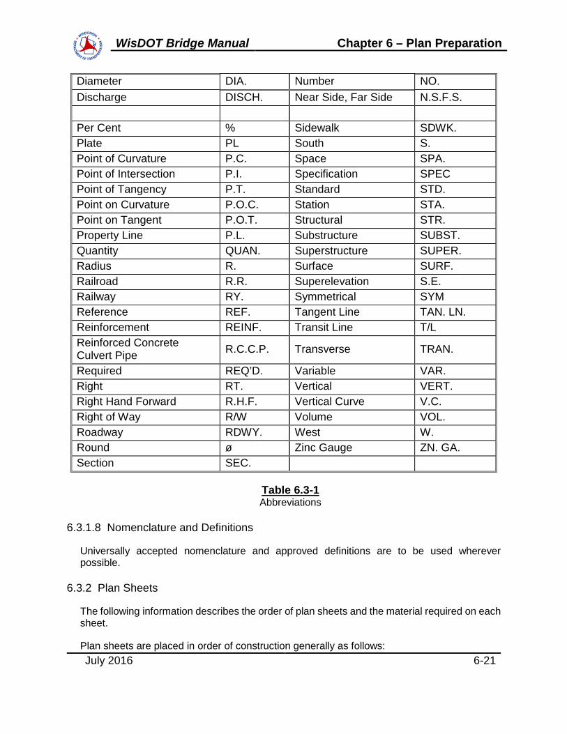
6.3.1.7 Abbreviations
Abbreviations are to be used throughout the plans whenever possible. Abbreviations approved to be used are as follows:
Abutment ABUT. East E. Adjacent ADJ. Elevation EL. Alternate ALT. Estimated EST. And & Excavation EXC. Approximate APPROX. Expansion EXP. At @ Fixed F. Back Face B.F. Flange Plate Fl. Pl. Base Line B/L Front Face F.F. Bench Mark B.M. Galvanized GALV. Bearing BRG. Gauge GA. Bituminous BIT. Girder GIR. Cast-in-Place C.I.P. Highway HWY. Centers CTRS. Horizontal HORIZ. Center Line C/L Inclusive INCL. Center to Center C to C Inlet INL. Column COL. Invert INV. Concrete CONC. Left LT. Construction CONST. Left Hand Forward L.H.F. Continuous CONT. Length of Curve L. Corrugated Metal Culvert Pipe C.M.C.P. Live Load L.L.
Cross Section X-SEC. Longitudinal LONGIT. Dead Load D.L. Maximum MAX. Degree of Curve D. Minimum MIN. Degree ° Miscellaneous MISC. Diaphragm DIAPH. North N.
WisDOT Bridge Manual Chapter 6 – Plan Preparation
July 2016 6-21
Diameter DIA. Number NO. Discharge DISCH. Near Side, Far Side N.S.F.S. Per Cent % Sidewalk SDWK. Plate PL South S. Point of Curvature P.C. Space SPA. Point of Intersection P.I. Specification SPEC Point of Tangency P.T. Standard STD. Point on Curvature P.O.C. Station STA. Point on Tangent P.O.T. Structural STR. Property Line P.L. Substructure SUBST. Quantity QUAN. Superstructure SUPER. Radius R. Surface SURF. Railroad R.R. Superelevation S.E. Railway RY. Symmetrical SYM Reference REF. Tangent Line TAN. LN. Reinforcement REINF. Transit Line T/L Reinforced Concrete Culvert Pipe R.C.C.P. Transverse TRAN.
Required REQ’D. Variable VAR. Right RT. Vertical VERT. Right Hand Forward R.H.F. Vertical Curve V.C. Right of Way R/W Volume VOL. Roadway RDWY. West W. Round ø Zinc Gauge ZN. GA. Section SEC.
Table 6.3-1 Abbreviations
6.3.1.8 Nomenclature and Definitions
Universally accepted nomenclature and approved definitions are to be used wherever possible.
6.3.2 Plan Sheets
The following information describes the order of plan sheets and the material required on each sheet.
Plan sheets are placed in order of construction generally as follows:

WisDOT Bridge Manual Chapter 6 – Plan Preparation
July 2016 6-22
1. General Plan
2. Subsurface Exploration
3. Abutments
4. Piers
5. Superstructure and Superstructure Details
6. Railing and Parapet Details
Show all views looking up station.
6.3.2.1 General Plan (Sheet 1)
See the BOS web page, CADD Resource Files, for the latest sheet borders to be used. Sheet borders are given for new bridges, rehabilitation projects and concrete box culverts. A superstructure replacement utilizing the existing substructure, bridge widenings, as well as damaged girder replacements should use the sheet border for a new structure. See Chapter 40 - Bridge Rehabilitation for criteria as to when superstructure replacements are allowed.
1. Plan View
Same requirements as specified for preliminary drawing, except do not show contours of groundline and as noted below.
a. Sufficient dimensions to layout structure in the field.
b. Describe the structure with a simple note such as: Four span continuous steel girder structure.
c. Station at end of deck on each end of bridge.
On Structure Replacements
Show existing structure in dashed-lines on Plan View.
2. Elevation View
Same requirements as specified for preliminary plan except:
a. Show elevation at bottom of all substructure units.
b. Give estimated pile lengths where used.
3. Cross-Section View
Same requirements as specified for preliminary plan except:

WisDOT Bridge Manual Chapter 6 – Plan Preparation
July 2016 6-23
a. For railroad bridges show a railroad cross-section.
b. View of pier if the bridge has a pier (s), if not, view of abutment.
4. Grade Line
Same requirements as specified for preliminary plan.
5. Design and Traffic Data
Same requirements as specified for preliminary plans, plus see 6.3.2.1 for guidance regarding sheet border selection.
6. Hydraulic Information, if Applicable
7. Foundations
Give soil/rock bearing capacity or pile capacity.
Example for General Plan sheet: Abutments to be supported on HP 10 x 42 steel piling driven to a required driving resistance of 180 tons * per pile as determined by the Modified Gates Dynamic Formula. Estimated 50’-0” long.
*The factored axial resistance of piles in compression used for design is the required driving resistance multiplied by a resistance factor of 0.5 using modified Gates to determine driven pile capacity.
Abutments with spread footings to be supported on sound rock with a required factored bearing resistance of “XXX” PSF ***. A geotechnical engineer, with three days notice, will determine the factored bearing resistance by visual inspection prior to construction of the abutment footing.
*** The factored bearing resistance is the value used for design.
Repeat the note above on each substructure sheet, except the asterisk (*) and subsequent explanation of factored design resistance need not appear on individual substructure sheets.
See Table 11.3-5 for typical maximum driving resistance values.
8. Estimated Quantities
a. Enter bid items and quantities as they appear, and in the order in which they appear in the "Schedule of Bid Items" of the Standard Specifications. Put items not provided for at the bottom of the list. Enter quantities for each part of the structure, (superstructure, each abutment, each pier) under a separate column with a grand total.
Quantities are to be bid under items for the Structure Type and not by the "B" or "C" numbers. For example, concrete for a multi-cell box culvert exceeding a

WisDOT Bridge Manual Chapter 6 – Plan Preparation
July 2016 6-24
total length of 20 feet is to be bid under item Concrete Masonry Culverts. As another example, a bridge having a length less than 20 feet would be given a "C" number; however, the concrete bid item is Concrete Masonry Bridges.
b. For incidental items to be furnished for which there is no bid item, and compensation is not covered by the Standard Specifications or Special Provisions, note on the plans the most closely related bid item that is to include the cost in the price bid per unit of item. As an example, the cost of concrete inserts is to be included in the price bid per cubic yard of concrete masonry.
9. General Notes
A standard list of notes is given in 6.3.2.1.1 and 6.3.2.1.2. Use the notes that apply to the structure drawn on the plans.
10. List of Drawings
Each sheet is numbered sequentially beginning with 1 for the first sheet. Give the sheet number and title of sheet.
11. Bench Marks
Give the location, description and elevation of the nearest bench mark.
12. Title Block
Fill in all data for the Title Block except the signature. The title of this sheet is "General Plan". Use the line below the structure number to describe the type of crossing. (Example: STH 15 SB OVER FOX RIVER). See 6.3.2.1 for guidance regarding sheet border selection.
13. Professional Seal
All final bridge plans prepared by Consultants or Governmental Agencies shall be professionally sealed, signed, and dated on the general plan sheet. If the list of drawings is not on the general plan sheet, the sheet which has the list of drawings shall also be professionally sealed, signed, and dated. This is not required for WisDOT prepared plans, as they are covered elsewhere.
6.3.2.1.1 Plan Notes for New Bridge Construction
1. Drawings shall not be scaled. Bar Steel Reinforcement shall be embedded 2” clear unless otherwise shown or noted.
2. All field connections shall be made with 3/4” diameter friction type high-tensile strength bolts unless shown or noted otherwise.
3. Slab falsework shall be supported on piles or the substructure unless an alternate method is approved by the Engineer.

WisDOT Bridge Manual Chapter 6 – Plan Preparation
July 2016 6-25
4. The first or first two digits of the bar mark signifies the bar size.
5. The slope of the fill in front of the abutments shall be covered with heavy riprap and geotextile fabric Type ‘HR’ to the extent shown on sheet 1 and in the abutment details.
6. The slope of the fill in front of the abutments shall be covered with slope paving material to the extent shown on sheet 1 and in the abutment details.
7. The stream bed in front of the abutment shall be covered with riprap as shown on this sheet and in the abutment details.
8. The existing stream bed shall be used as the upper limits of excavation at the piers.
9. The existing ground line shall be used as the upper limits of excavation at the piers.
10. Within the length of the box all spaces excavated and not occupied by the new structure shall be backfilled with Structure Backfill to the elevation and section existing prior to excavation within the length of the culvert.
11. At the backface of abutment all volume which cannot be placed before abutment construction and is not occupied by the new structure shall be backfilled with structure backfill.
12. Concrete inserts to be furnished by the utility company and placed by the contractor. Cost of placing inserts shall be included in the bid price for concrete masonry.
13. Prestressed Girder Bridges - The haunch concrete quantity is based on the average haunch shown on the Prestressed Girder Details sheet.
14. The quantity for Backfill Structure, bid item 210.0100, is calculated based on the applicable Figures 12.6-1 and 12.6-2 in the Wisconsin Department of Transportation Bridge Manual.
6.3.2.1.2 Plan Notes for Bridge Rehabilitation
WisDOT policy item:
The note “Dimensions shown are based on the original structure plans” is acceptable. However, any note stating that the contractor shall field verify dimensions is not allowed.
It is the responsibility of the design engineer to use original structure plans, as-built structure plans, shop drawings, field surveys and structure inspection reports as appropriate when producing rehabilitation structure plans of any type (bridges, retaining walls, box culverts, sign structures, etc.). If uncertainty persists after reviewing available documentation, a field visit may be necessary by the design engineer.
1. Dimensions shown are based on the original structure plans.

WisDOT Bridge Manual Chapter 6 – Plan Preparation
July 2016 6-26
2. All concrete removal not covered with a concrete overlay shall be defined by a 1 inch deep saw cut.
3. Utilize existing bar steel reinforcement where shown and extend 24 bar diameters into new work, unless specified otherwise.
4. Concrete expansion bolts and inserts to be furnished and placed by the contractor under the bid price for concrete masonry.
5. At "Curb Repair" expose existing reinforcement a minimum of 1 1/2” clear.
6. Existing floor drains to remain in place. Remove top of deck in drain area as directed by the Field Engineer to allow placing and sloping of 1 1/2” concrete overlay.
7. Expansion joint assembly, including anchor studs and hardware shall be paid for in the lump sum price bid as "Expansion Device B-_____” or “Expansion Device Modular B- ______”.
8. Clean and fill existing longitudinal and transverse cracks with penetrating epoxy as directed by the Field Engineer.
9. Variations to the new grade line over 1/4” must be submitted by the Field Engineer to the Structures Design Section for review.
10. The contractor shall supply a new name plate in accordance with Section 502.3.11 of the Standard Specifications and the standard detail drawings. Name plate to show original construction year.
6.3.2.2 Subsurface Exploration
This sheet is initiated by the Geotechnical Engineer. The following information is required on the sheet. Bridge details are not drawn by the Geotechnical Engineer.
1. Plan View
Show a plan layout of structure with survey lines, reference lines, pier and abutment locations and location of borings and probings plotted to scale.
On box culvert structure plans, show three profile lines of the existing ground elevations (along the centerline and outer walls of the box). Scale the information for these lines from the site contour map that is a part of the structure survey report.
2. Elevation
Show a centerline profile of existing ground elevation.
Show only substructure units at proper elevation w/no elevations shown. Also show the pile lengths.
WisDOT Bridge Manual Chapter 6 – Plan Preparation
July 2016 6-27
Show the kind of material, its located depth, and the blow count of the split spoon sampler for each boring. Give the blow count at about 5 foot intervals or where there is a significant change in material.
6.3.2.3 Abutments
Use as many sheets as necessary to show details clearly. Each substructure unit should have its own plan sheet(s). Show all bar steel required using standard notations; solid lines lengthwise and solid dots in cross section. Give dimensions for a skewed abutment to a reference line which passes through the intersection for the longitudinal structural reference line and centerline of bearing of the abutment. Give the dimension, from centerline of bearing to backface of abutment along the longitudinal reference line and the offset distance if on a skew. Show the skew angle.
If there is piling, show a complete footing layout giving piling dimensions tied to the reference line. Number all the piles. Give the type of piling, length and required driving resistance. Show a welded field splice for cast in place concrete or steel H piles.
Bridge seats for steel bearings and laminated elastomeric bearings are level within the limits of the bearing plate. Slope the bearing area utilizing non-laminated elastomeric bearings if the slope of the bottom of girder exceeds 1%. Slope the bridge seat between bearings 1” from front face of backwall to front face of abutment. Give all beam seat elevations.
1. Plan View
a. Place a keyed construction joint near the center of the abutment if the length of the body wall exceeds 50 feet. Make the keyway as large as feasible and extend the horizontal bar steel through the joint.
b. Dimension wings in a direction parallel and perpendicular to the wing centerline.
c. Dimension angle between wing and body if that angle is different from the skew angle of the abutment.
2. Elevation
a. Give beam seat, wing (front face and wing tip), and footing elevations to the nearest .01 of a foot.
b. Give vertical dimension of wing.
3. Wing Elevation
4. Body Section
Place an optional keyed construction joint in the parapet at the bridge seat elevation if there is a parapet.
5. Wing Sections

WisDOT Bridge Manual Chapter 6 – Plan Preparation
July 2016 6-28
6. Bar Steel Listing and Detail
Use the following views where necessary:
7. Pile Plan & Splice Detail
8. View Showing Limits of Excavation and Backfill
9. Special Details for Utilities
10. Drainage Details
6.3.2.4 Piers
Use as many sheets as necessary to show all details clearly. Each substructure unit should have its own plan sheet(s).
Give dimensions for a skewed pier to a reference line which passes through the intersection of the longitudinal structural reference line and the pier centerline. Show the skew angle. Dimension the centerline spacing of superstructure girders.
1. Plan View
Show dimensions, footings, cap steps, beam spacings and skew angle.
2. Elevation
Show dimensions and elevations. Show lengths of all columns for clarity. Give the elevation of the bottom of footings and beam seats. Refer to abutments for detailing bridge seats. Dimension all bar steel and stirrups.
3. Footing Plan
Show dimensions for pile spacing, pile numbers and reinforcing steel in footing.
4. Bar Steel Listing and Details
5. Pile Splice Detail (If different from abutment only).
6. Cross Section thru Column and Pier Cap
Detail anchor bolts between reinforcing bars to provide clearance. Long steel bridges may require more clearance. This allows an erection tolerance for the structural steel so that the bar steel is not pierced by the anchor bolts if the bearing is shifted.

WisDOT Bridge Manual Chapter 6 – Plan Preparation
July 2016 6-29
6.3.2.5 Superstructure
Use as many sheets as are necessary to show all details clearly. Standard insert sheets are available to show many standard details. The title, project number, and a few basic dimensions are added to these standard sheets.
6.3.2.5.1 All Structures
1. Show the cross-section of roadway, plan view and related details, elevation of typical girder or girders, details of girders, and other details not shown on standard insert sheets. All drawings are to be fully dimensioned and show such sections and views as needed to detail the superstructure completely.
2. For girder bridges: Show the total dead load deflections, including composite dead load (without future wearing surface) acting on the composite section, at tenth points of each span. Distribute the composite dead load evenly to all girders and provide one deflection value for a typical interior girder. Chapter 17 – Superstructure-General illustrates three load cases for exterior girder design with raised sidewalks, cases that provide a conservative envelope to ensure adequate girder capacity. However, the above composite dead load distribution should be used for deflection purposes. For prestressed concrete girders, the dead load deflection reported does not include the weight of the girder. See Chapter 24 – Steel Girder Structures for camber and blocking, top of steel elevation and deflection reporting criteria.
A separate deflection value for interior and exterior girders may be provided if the difference, accounting for load transfer between girders, warrants multiple values. A weighted distribution of composite dead load could be used for deflection purposes only. For example, an extremely large composite load over the exterior girder could be distributed as 40-30-30 percent to the exterior and first two interior girders respectively. Use good engineering judgment to determine whether to provide separate deflection values for individual girder lines. In general, this is not necessary.
For slab bridges: Provide camber values at the tenth points of all spans. The camber is based on 3 times the deflection of the slab, only. For multi-span bridges, the deflection calculations are based on a continuous span structure since the falsework supports the bridge until the concrete slab has cured.
Deflection and camber values are to be reported to the nearest 0.1 inch, for all girder and slab superstructures.
3. For girder structures, provide finished grade top of deck elevations for each girder line at the tenth points of all spans. Show the top of deck elevations at the outside edge of deck at tenth points. If staged construction, include tenth point elevations along the construction joint. For slab structures, provide the finished grade elevations at the reference line and/or crown and edge of slab at tenth points.

WisDOT Bridge Manual Chapter 6 – Plan Preparation
July 2016 6-30
4. Decks of uniform thickness are used on all girders. Variations in thickness are achieved by haunching the deck over each girder. Haunches are formed off the top of the top flange. See the standards for details. In general the minimum haunch depth along the edge of girder is to be 1 1/4” although 2” is recommended to allow for construction tolerances. Haunch depth is the distance from the bottom of the concrete deck to the top of the top flange.
5. Provide a paving notch at each end of all structures for rigid approach pavements. See standard for details.
6. If the structure contains conduit for a deck lighting system, place the conduit in the concrete parapet. Place expansion devices on conduit which passes through structure expansion joints.
7. Show the bar steel reinforcement in the slab, curb, and sidewalk with the transverse spacing and all bars labeled. Show the direction and amount of roadway crown.
8. On bridges with a median curb and left turn lane, water may be trapped at the curb due to the grade slope and crown slope. If this is the case, make the cross slope flat to minimize the problem. Existing pavers cannot adjust to a variable crown line.
9. On structures with modular joints consider cover plates for the back of parapets when aesthetics are a consideration.
10. Provide a table of tangent offsets for the reference line and edges of deck at 10 foot intervals for curved bridges.
6.3.2.5.2 Steel Structures
1. Show the diaphragm connections on steel girders. Show the spacing of rail posts on the plan view.
2. Show a steel framing plan for all steel girders. Show the spacing of diaphragms.
3. On the elevation view of steel girders show dimension, material required, field and shop splice locations, stiffener spacing, shear connector spacing, and any other information necessary to construct the girder. In additional views show the field splice details and any other detail that is necessary.
4. Show the size and location of all weld types with the proper symbols except for butt welds. Requirements for butt welds are covered by A.W.S. Specifications.
5. See Chapter 24 – Steel Girder Structures for camber and blocking, top of steel elevation and deflection reporting criteria.
6. Existing flange and web sizes should be shown to facilitate the sizing of bolts on Rehabilitation Plans.

WisDOT Bridge Manual Chapter 6 – Plan Preparation
July 2016 6-31
6.3.2.5.3 Railing and Parapet Details
Standard drawings are maintained by the Structures Development Section showing railing and parapet details. Add the details and dimensions to these drawings that are unique to the structure being detailed. Compute the length along the slope of grade line rather than the horizontal dimension.
6.3.3 Miscellaneous Information
6.3.3.1 Bill of Bars
Show a complete bill of bar steel reinforcement for each unit of the structure. Place this bill on the sheet to which the bars pertain. If the abutments or piers are similar, only one bar list is needed for each type of unit.
Give each bar or group of bars a different mark if they vary in size, length, or location in a unit. Each bar list is to show the mark, number of bars, length, location and detail for each bar. Give bar lengths to the nearest 1” and segment lengths of bent bars to the nearest 1/2”. Show all bar bends and hooks in detail.
Identify all bars with a letter indicating the unit in which the bar is placed - A for abutment, P for pier, S for superstructure. Where units are multiple, each unit should have a different letter. Next use a one or two digit number to sequentially number the bars in a unit. P1008 indicates bar number 08 is a size number 10 bar located in a Pier.
Use a Bar Series Table where a number of bars the same size and spacing vary in length is a uniform progression. Use only one mark for all these bars and put the average length in the table.
Refer to the Standard drawings in Chapter 9 – Materials for more information on reinforcing bars such as minimum bend diameter, splice lengths, bar supports, etc.
When a bridge is constructed in stages, show the bar quantities for each stage. This helps the contractor with storage and retrieval during construction.
6.3.3.2 Box Culverts
Detail plans for box culverts are to be fully dimensioned and have sectional drawings needed to detail the structure completely. The following items are to be shown when necessary:
1. Plan View
2. Longitudinal section
3. Section thru box
4. Wing elevations
5. Section thru wings

WisDOT Bridge Manual Chapter 6 – Plan Preparation
July 2016 6-32
6. Section thru cutoff wall
7. Vertical construction joint
8. Bar steel clearance details
9. Header details
10. North point, Bench mark, Quantities
11. Bill of bars, Bar details
12. General notes, List of drawings, Rip rap layout
13. Inlet nose detail on multiple cell boxes
14. Corner details
Bid items commonly used are excavation, concrete masonry, bar steel, rubberized membrane waterproofing, backfill and rip rap. Filler is a non-bid item. In lieu of showing a contour map, show profile grade lines as described for Subsurface Exploration sheet.
See the standard details for box culverts for the requirements on vertical construction joints, apron and cutoff walls, longitudinal construction joints, and optional construction joints.
Show name plate location on plan view and on wing detail.
6.3.3.3 Miscellaneous Structures
Detail plans for other structures such as retaining walls, pedestrian bridges, and erosion control structures are to be detailed with the same requirements as previously mentioned. Multiple sign structure of the same type and project may be combined into a single set of plans per standard insert sheet provisions, and shall be subject to the same requirements for bridge plans.
6.3.3.4 Standard Drawings
Standard drawings are maintained and furnished by the Structures Development Section. These drawings show the common types of details required on the contract plans.
6.3.3.5 Insert Sheets
These sheets are maintained by the Structures Development Section and are used in the contract plans to show standard details.
6.3.3.6 Change Orders and Maintenance Work
These plans are drawn on full size sheets. A Structure Survey Report should be submitted for all maintenance projects, including painting projects and polymer overlay projects. In addition

WisDOT Bridge Manual Chapter 6 – Plan Preparation
July 2016 6-33
to the SSR, final structure plans on standard sheet borders with the #8 tab should be submitted to BOS in the same fashion as other rehabilitation plans. Painting plans should include at minimum a plan view with overall width and length dimensions, the number of spans, an indication of the number and type of elements to be painted (girders, trusses, etc.), and an elevation view showing what the structure is crossing. The SSR should give a square foot quantity for patchwork painting. For entire bridges or well defined zones (e.g. Paint all girders 5 feet on each side of expansion joints), the design engineer will be responsible for determining the quantity.
6.3.3.7 Name Plate and Bench Marks
WisDOT has discontinued the statewide practice of furnishing bench mark disks and requiring them to be placed on structures. However, WisDOT Region Offices may continue to provide bench mark disks for the contract to be set. Bench mark disks shall be shown on all bridge and larger culvert plans. Locate the bench mark disks on a horizontal surface flush with the concrete. Bench marks to be located on top of the parapet on the bridge deck, above the first right corner of the abutment traveling in the highway cardinal directions of North or East. For multi-directional bridges, locate the name plate on the roadway side of the first right wing or parapet traveling in the highway cardinal directions of North or East. For one-directional bridges, locate the name plate on the first right wing or parapet in the direction of travel. For type “NY”, “W”, “M” or timber railings, name plate to be located on wing. For parapets, name plate to be located on inside face of parapet.
6.3.4 Checking Plans
Upon completion of the design and drafting of plans for a structure, the final plans are usually checked by one person. Dividing plans checking between two or more Checkers for any one structure leads to errors many times. The plans are checked for compliance with the approved preliminary drawing, design, sufficiency and accuracy of details, dimensions, elevations, and quantities. Generally the information shown on the preliminary plan is to be used on the final plans. Revisions may be made to footing sizes and elevations, pile lengths, dimensions, girder spacing, column shapes, and other details not determined at the preliminary stage. Any major changes from the preliminary plan are to be approved by the Structural Design Engineer and Supervisor.
The Checkers check the final plans against the Engineer's design and sketches to ensure all information is shown correctly. The Engineer prepares all sketches and notations not covered by standard drawings. A good Checker checks what is shown and noted on the plan and also checks to see if any essential details, dimensions, or notation have been omitted. The final plan Bid Items should be checked for conformity with those listed in the WisDOT Standard Specifications for Highway and Structure Construction.
The Checker makes an independent check of the Bill of Bars list to ensure the Plan Preparer has not omitted any bars when determining the quantity of bar steel.
Avoid making minor revisions in details or dimensions that have very little effect on cost, appearance, or adequacy of the completed structure. Check grade and bridge seat elevations and all dimensions to the required tolerances. The Checkers make all corrections, revisions, and notations on a print of the plan and return it to the Plan Preparer. The Plan Preparer back

WisDOT Bridge Manual Chapter 6 – Plan Preparation
July 2016 6-34
checks all marks made by the Checker before changing. Any disagreements are resolved with the Supervisor.
Common complaints received from field staff are dimension errors, small details crowded on a drawing, lettering is too small, and reinforcing bar length or quantity errors.
After the plans are completed, the items in the project folder are separated into the following groups by the Structures Design Engineer:
6.3.4.1 Items requiring a PDF copy for the Project Records (Group A) – Paper Copies to be Destroyed when Construction is Completed.
1. QC/QA sign-off sheet
2. Design computations and computer runs
3. Quantity computations
4. Bridge Special Provisions and STSP’s (only those STSP’s requiring specific blanks to be filled in or contain project specific information)
5. Final Structure Survey Report form (not including photos, cross-sections, project location maps, etc.)
6. Final Geotechnical Report
7. Final Hydrology and Hydraulic computations and structure sizing report
8. Contour map
6.3.4.2 Additional Items to be Destroyed When Construction is Completed (Group B)
1. Miscellaneous correspondence and transmittal letters
2. Preliminary drawings and computations
3. Prints of soil borings and plan profile sheets
4. Shop steel quantity computations*
5. Design checker computations
6. Layout sheets
7. Elevation runs and bridge geometrics
8. Falsework plans*
9. Miscellaneous Test Report

WisDOT Bridge Manual Chapter 6 – Plan Preparation
July 2016 6-35
10. Photographs of bridge rehabs
* These items are added to the packet during construction.
6.3.4.3 Items to be Destroyed when Plans are Completed (Group C)
1. All "void" material
2. All copies except one of preliminary drawings
3. Extra copies of plan and profile sheets
4. Preliminary computer design runs
Note that lists for Group A, B & C are not intended to be all inclusive, but serve as starting points for categorizing design material. Items in Group A & B should be labeled separately. Computation of Quantities

WisDOT Bridge Manual Chapter 6 – Plan Preparation
July 2016 6-36
6.4 Computation of Quantities
When the final drafting and plan checking is completed, the person responsible for drafting the plans and plans checker are to prepare individual quantity calculations for the bid items listed on the plans. The following instructions apply to the computation on quantities.
Divide the work into units that are repetitive such as footings, columns, and girders. Label all items with a clear description. Use sketches for clarity. These computations may be examined by others in future years so make them understandable.
One of the most common errors made in quantity computation is computing only half of an item which is symmetrical about a centerline and forgetting to double the result.
Following is a list of commonly used bridge quantities. Be sure to use the appropriate item and avoid using incidental items as this is too confusing for the contractor and project manager. The bid item for Abatement of Asbestos Containing Material should be included on the structure plans. Items such as Incentive Strength Concrete Structures, Construction Staking Structure Layout, etc. should not be included on the structure plans.
A column with the title “Bid Item Number” should be the first column for the “Total Estimated Quantities” table shown in the plans. The numbers in this column will be the numbers associated with the bid items as found in the Standard Specification, STSP, and/or Special Provisions.
6.4.1 Excavation for Structures Bridges (Structure)
This is a lump sum bid item. The limits of excavation are shown in the chapter in the manual which pertains to the structural item, abutments, piers, retaining walls, box culverts, etc. If the excavation is required for the roadway, the work may be covered under Excavation Common.
The limits of excavation made into solid rock are the neat line of the footing.
6.4.2 Granular Materials
Granular materials can be bid in units of tons or cubic yards. Structure plans should use the TON bid item for Structure Backfill, Granular Backfill, and Base Aggregate Dense 1 1/4-inch, unless directed otherwise by the Region. The Region may consider use of the CY bid item when contractor-provided tickets may be problematic or when the TON bid item is not used elsewhere on the contract. Other cases may also warrant the use of the CY bid item.
For Structure Backfill, Granular Backfill, and Base Aggregate Dense 1 1/4-inch materials use a 2.0 conversion factor (tons/cubic yard) for compacted TON bid items or use a 1.20 expansion factor (i.e. add an additional 20%) for CY bid items, unless directed otherwise. Refer to the FDM when preparing computations using other granular materials (breaker run, riprap, etc.).
Granular quantities and units should be coordinated with the roadway designer. For some structures, backfill quantities may be negligible to the roadway, while others may encompass a large portion of the roadway cross section and be present in multiple cross sections. A long

WisDOT Bridge Manual Chapter 6 – Plan Preparation
July 2016 6-37
MSE retaining wall would be an example of the latter case and will require coordination with the roadway designer.
Generally, granular material pay limits should be shown on all structure plans. This information should be used to generate the estimated quantities and used to coordinate with roadway cross sections and construction details. See Standard Detail 9.01 – Structure Backfill Limits and Notes - for typical pay limits and plan notes.
Refer to 9.10 for additional information about granular materials.
6.4.3 Concrete Masonry Bridges
Show unit quantities to the nearest cubic yard, as well as the total quantity. In computing quantities no deduction is made for metal reinforcement, floor drains, conduits and chamfers less than 2”. Flanges of steel and prestressed girders projecting into the slab are deducted.
Deduct the volume of pile heads into footings and through seals for all piling except steel H sections. Deduct the actual volume displaced for precast concrete and cast-in-place concrete piling.
Consider the concrete parapet railing on abutment wing walls as part of the concrete volume of the abutment.
6.4.4 Prestressed Girder Type I (28-Inch; 36-Inch; 36W-Inch; 45W-Inch; 54W-Inch; 72W-Inch, 82W-Inch)
Record the total length of prestressed girders to the nearest 1 foot.
6.4.5 Bar Steel Reinforcement HS Bridges or Bar Steel Reinforcement HS Coated Bridges
Record this quantity to the nearest 10 lbs. Designate if bar steel is coated. Include the bar steel in C.I.P. concrete piling in bar steel quantities.
6.4.6 Bar Steel Reinforcement HS Stainless Bridges
Record this quantity to the nearest 10 lbs. Bar weight shall be assumed to be equivalent to Bar Steel Reinforcement HS Bridges or Bar Steel Reinforcement HS Coated Bridges bid items.
6.4.7 Structural Steel Carbon or Structural Steel HS
See 24.2.4.
6.4.8 Bearing Pads Elastomeric Non-Laminated or Bearing Pads Elastomeric Laminated or Bearing Assemblies Fixed (Structure) or Bearing Assemblies Expansion (Structure)
Record as separate item with quantity required. Bid as Each.
WisDOT Bridge Manual Chapter 6 – Plan Preparation
July 2016 6-38
6.4.9 Piling Test Treated Timber (Structure)
Record this quantity as a lump sum item. Estimate the pile lengths by examining the subsurface exploration sheet and the Site Investigation Report. Give the length and location of test piles in a footnote. Do not use this quantity for steel piling or concrete cast-in-place piling.
6.4.10 Piling CIP Concrete Delivered and Driven ___-Inch, Piling Steel Delivered and Driven ___ -Inch
Record this quantity in feet for Steel and C.I.P. types of piling delivered and driven. Timber piling are Bid as separate items, delivered and driven. Pile lengths are computed to the nearest 5.0 foot for each pile within a given substructure unit, unless a more exact length is known due to well defined shallow rock (approx. 20 ft.), etc.. Typically, all piles within a given substructure unit are shown as the same length.
The length of foundation piling driven includes the length through any seal and embedment into the footing. The quantity delivered is the same as quantity driven. For trestle piling the amount of piling driven is the penetration below ground surface.
Oil field pipe is allowed as an alternate on all plans unless a note is added in the General Notes stating it is not allowed on that specific project.
6.4.11 Preboring CIP Concrete Piling or Steel Piling
Record the type, quantity in feet. Calculate to the nearest lineal foot per pile location.
6.4.12 Railing Steel Type (Structure) or Railing Tubular Type (Structure)
Record the type and quantity, bid in lineal feet. For bridges, the railing length should be horizontal length shown on the plans. For retaining walls, use the length along the top of the wall. Calculate railing lengths as follows:
• Steel Railing Type ‘W’ – CL end post to CL end post
• Tubular Railing Type ‘H’ – CL end plate to CL end plate
• Combination Railing Type ‘3T’ – CL end post to CL end post + (2’-5”) per railing
• Tubular Railing Type ‘M’ – CL end post to CL end post + (4’-6”) per railing
• Combination Railing Type ‘Type C1-C6’ – CL end rail base plate to CL end rail base plate
• Tubular Steel Railing Type NY3&4 – CL end post to CL end post + (4’-10”) per railing

WisDOT Bridge Manual Chapter 6 – Plan Preparation
July 2016 6-39
6.4.13 Slope Paving Concrete or Slope Paving Crushed Aggregate or Slope Paving Select Crushed Material
Record this quantity to the nearest square yard. Deduct the area occupied by columns or other elements of substructure units.
6.4.14 Riprap Medium, Riprap Heavy or Grouted Riprap, Riprap Light
Record this quantity to the nearest 5 cubic yards.
6.4.15 Pile Points
When recommended in soils report. Bid as each.
6.4.16 Floordrains Type GC, Floordrains Type H, or Floordrains Type WF
Record the type and number of drains. Bid as Each.
6.4.17 Cofferdams (Structure)
Lump Sum
6.4.18 Rubberized Membrane Waterproofing
Record the quantity to the nearest square yard.
6.4.19 Expansion Devices
For “Expansion Device” and “Expansion Device Modular”, bid the items in lineal feet. The distance measured is from flowline to flowline along the skew (do not include turn-ups into parapets or medians).
6.4.20 Electrical Work
Refer to Standard Construction Specifications for bid items.
6.4.21 Conduit Rigid Metallic __-Inch or Conduit Rigid Nonmetallic Schedule 40 -Inch
Record this quantity in feet.
6.4.22 Preparation Decks Type 1 or Preparation Decks Type 2
Record these quantities to the nearest square yard. Preparation Decks Type 1 should be provided by the Region. Estimate Preparation Decks Type 2 as 40% of Preparation Decks Type 1. Deck preparation areas shall be filled using Concrete Masonry Overlay Decks, Concrete Masonry Deck Patching, or with an appropriate deck patch. See Chapter 40 Standards.

WisDOT Bridge Manual Chapter 6 – Plan Preparation
July 2016 6-40
6.4.23 Cleaning Decks
Record this quantity to the nearest square yard.
6.4.24 Joint Repair
Record this quantity to the nearest square yard.
6.4.25 Concrete Surface Repair
Record this quantity to the nearest square foot.
6.4.26 Full-Depth Deck Repair
Record this quantity to the nearest square yard.
6.4.27 Concrete Masonry Overlay Decks
Record this quantity to the nearest cubic yard. Estimate the quantity by using a thickness measured from the existing ground concrete surface to the plan gradeline. Calculate the minimum overlay thickness and add ½” for variations in the deck surface. Provide this average thickness on the plan, as well. Usually 1” of deck surface is removed by grinding. Include deck repair quantities for Preparation Decks Type 1 & 2 and Full-Depth Deck Repair. Use 2-inch thickness for each Preparation area and ½ the deck thickness for Full-Depth Deck Repairs in areas of deck preparation (full-depth minus grinding if no deck preparation).
6.4.28 Removing Old Structure STA. XX + XX.XX
Covers the entire or partial removal of an existing structure. Bid as Lump Sum.
6.4.29 Anchor Assemblies for Steel Plate Beam Guard
Attachment assembly for Beam Guard at the termination of concrete parapets. Bid as each.
6.4.30 Steel Diaphragms (Structure)
In span diaphragms used on bridges with prestressed girders. Bid as each.
6.4.31 Welded Stud Shear Connectors X -Inch
Total number of shear connectors with the given diameter. Bid as each.
6.4.32 Concrete Masonry Seal
Seal concrete bid to the nearest cubic yard. Whenever a concrete seal is shown on the plans, then “Cofferdams (Structure)” is also to be a bid item.

WisDOT Bridge Manual Chapter 6 – Plan Preparation
July 2016 6-41
6.4.33 Geotextile Fabric Type
List type of fabric. Type HR is used in conjunction with Heavy Riprap. Bid in square yards.
6.4.34 Concrete Adhesive Anchors
Used when anchoring reinforcing bars into concrete. Bid as each.
6.4.35 Piling Steel Sheet Permanent Delivered or Piling Steel Sheet Permanent Driven
Record this quantity to the nearest square foot for the area of wall below cutoff.
6.4.36 Piling Steel Sheet Temporary
This quantity is used when the designer determines that retention of earth is necessary during excavation and soil forces require the design of steel sheet piling. This item is seldom used now that railroad excavations have a unique SPV.
Record this quantity to the nearest square foot for the area from the sheet pile tip elevation to one foot above the retained grade.
6.4.37 Temporary Shoring
This quantity is used when earth retention may be required and the method chosen is the contractor’s option.
Measured as square foot from the ground line in front of the shoring to a maximum of one foot above the retained grade. For the estimated quantity use the retained area (from the ground line in front of the shoring to the ground line behind the shoring, neglecting the additional height allowed for measurement).
6.4.38 Concrete Masonry Deck Patching
Record this quantity to the nearest cubic yard. Use 2-inch thickness for each Preparation area and ½ the deck thickness for Full-Depth Deck Repairs.
6.4.39 Sawing Pavement Deck Preparation Areas
Use 10 lineal feet per SY of Preparation Decks Type 1.
6.4.40 Removing Bearings
Used to remove existing bearings for replacement with new expansion or fixed bearing assemblies. Bid as each.

WisDOT Bridge Manual Chapter 6 – Plan Preparation
July 2016 6-42
6.4.41 Ice Hot Weather Concreting
Used to provide a mechanism for payment of ice during hot weather concreting operations. See FDM 19-7-1.2 for bid item usage guidance and quantity calculation guidance. Bid as LB and round to the nearest 5 lbs.

WisDOT Bridge Manual Chapter 6 – Plan Preparation
July 2016 6-43
6.5 Production of Structure Plans by Consultants, Regional Offices and Other Agencies
The need for structures is determined during the Preliminary Site Survey and recorded in the Concept Definition or Work Study Report. On Federal (FHWA) or State Aid Projects (including maintenance projects), a completed Structure Survey Reports, preliminary and final plans are submitted to the Bureau of Structures with a copy forwarded to the Regional Office for review and approval prior to construction. Structure and project numbers are provided by the Regional Offices. In preparation of the structural plans, the appropriate specifications and details recommended by the Bureau of Structures are to be used. If the consultant elects to modify or use details other than recommended, approval is required prior to their incorporation into the final plans.
On all Federal or State Aid Projects involving Maintenance work, the Concept Definition or Work Study Report, the preliminary and final bridge reconstruction plans shall be submitted to the Bureau of Structures for review.
Consultants desiring eligibility to perform engineering and related services on WisDOT administered structure projects must have on file with the Bureau of Structures, an electronic copy of their current Quality Assurance/Quality Control (QA/QC) plan and procedures. The QA/QC plan and procedures shall include as a minimum:
• Procedures to detect and correct bridge design errors before the design plans are made final.
• A means for verifying that the appropriate design calculations have been performed, that the calculations are accurate, and that the capacity of the load-carrying members is adequate with regard to the expected loads on the structure.
• A means for verifying the completeness, constructability and accuracy of the structure plans.
• Verification that independent checks, reviews and ratings were performed. A QA/QC verification summary sheet is required as part of every final structure plan submittal, demonstrating that the QA/QC plan and procedures were followed for that structure. The QA/QC verification summary sheet shall include the signoff or initialing by each individual that performed the tasks (design, checking, plan review, technical review, etc.) documented in the QA/QC plan and procedures. The summary sheet must be submitted with the final structure plans as part of the e-submit process.
6.5.1 Approvals, Distribution, and Work Flow
Consultant Meet with Regional Office and/or local units of government to determine need. Prepare Structure Survey Report including recommendation of structure type.
Geotechnical Consultant Make site investigation and prepare Subsurface Investigation Report.

WisDOT Bridge Manual Chapter 6 – Plan Preparation
July 2016 6-44
Consultant
Submit hydrology report via Esubmit or as an email attachment to the supervisor of the Consultant Review and Hydraulics Unit. Submit 60 days prior to preliminary plan submittal. Prepare preliminary plans according to 6.2. Coordinate with Region and other agencies per 6.2.3. Submit preliminary plans, SSR and supporting documents via e-submit for review and approval of type, size and location.
Structures Design Section Record project information in HSIS. Review hydraulics for Stream Crossings. Review Preliminary Plan. A minimum of 30 days to review preliminary plans should be expected. Coordinate with other agencies per 6.2.3. Return preliminary plans and comments from Structures Design Section and other appropriate agencies to Consultant with a copy to the Regional Office. Forward Preliminary Plan and Hydraulic Data to DNR.
Consultant Modify preliminary plan as required, and provide explanation for preliminary comments not incorporated in final plan. Prepare and complete final design and plans for the specified structure. Write special provisions. At least two months in advance of the PS&E date, submit the required final design documents via e-submit per 6.5.3.
Structures Design Section Determine which final plans will be reviewed and perform quality assurance review as applicable. For final plans that are reviewed, return comments to Consultant and send copy to Regional Office, including FHWA as appropriate.
Consultant Modify final plans and specifications as required. Submit modified final plans via e-submit as required.
Structures Design Section Review modified final plans as applicable. Sign final plans and send performance evaluation form to Region and Consultant.
Bureau of Project Development Prepare final accepted structure plans for pre-development contract administration.

WisDOT Bridge Manual Chapter 6 – Plan Preparation
July 2016 6-45
Consultant If a plan change is needed after being advertised but before being let, an addendum is required per FDM 19-22-1 and 19.1 Attachment 1.2.
Structures Design Section Review structure addendum as applicable. Sign structure addendum.
Bureau of Project Development Distributes structure addendum to bidders. Consultant If a plan change is required after being let, a
post-let revision is required per 6.5.5. Structures Design Section Review post-let revision as applicable.
Stamp post-let revision plan as accepted. Delivers revised plan to DOT construction team for distribution.
Table 6.5-1 Approvals, Distribution and Work Flow
6.5.2 Preliminary Plan Requirements
The Consultant prepares the Structure Survey Report for the improvement. Three types of Structure Survey Reports are available at the Regional Offices and listed in 6.2.1 of this Chapter. Preliminary layout requirements are given in 6.2.2. The Preliminary Plan exhibits are as follows:
1. Hydrology Report
2. Structure Survey Report
3. Preliminary plan, including log borings shown on the subsurface exploration sheet
4. Evaluation of subsurface investigation report
5. Contour map
6. Plan and profile, and typical section for roadway approaches
7. Hydraulic/Sizing Report (see Chapter 8 - Hydraulics) and hydraulic files are required for stream crossing structures
8. County map showing location of new and/or existing structures and FEMA map
9. Any other information or drawings which may influence location, layout or design of structure, including DNR initial review letter and photographs

WisDOT Bridge Manual Chapter 6 – Plan Preparation
July 2016 6-46
6.5.3 Final Plan Requirements
The guidelines and requirements for Final Plan preparation are given in 6.3. The Load Rating Summary form and On-Time Submittal form can be found on the Bureau of Structures’ Design and Construction webpage. The following files are included as part of the final-plan submittal:
1. Final Drawings
2. Design and Quantity Computations
For all structures for which a finite element model was developed, include the model computer input file(s).
3. Special Provisions covering unique items not in the Standard Specifications or Standardized Special Provisions (STSP).
4. QA/QC Verification Sheet
5. Inventory Data Sheet
6. Bridge Load Rating Summary Form
7. LRFD Input File (Excel ratings spreadsheet)
8. On-Time Improvement Form
The On-Time Improvement form is required to be submitted if either of the following situations occur:
• If the first version of a final structure plan is submitted after the deadline of two months prior to the PSE date.
• If any version of a final structure plan is re-submitted after the deadline of two months prior to the PSE date. However this form is not required when the re-submit is prompted by comments from the Consultant Review Unit. The form is also not necessary when submitting addenda or post-let revisions.
6.5.4 Addenda
Addenda are plan and special provision changes that occur after the bid package has been advertised to potential bidders. See FDM 19-22-1 for instruction on the addenda process.
6.5.5 Post-Let Revisions
Post-let revisions are changes to plan details after the contract is awarded to a bidder. ESubmit only the changed plan sheets, not the entire plan set. The changes to the plan sheet shall be in red font, and outlined by red clouding. The revision box shall also be filled in with red font. Each sheet shall be 11x17, PE stamped, signed, and dated on the date of submittal.

WisDOT Bridge Manual Chapter 6 – Plan Preparation
July 2016 6-47
6.5.6 Local-Let Projects
Local-let projects that are receiving State or Federal funding shall be submitted to and reviewed by the Consultant Review Unit in the same way as a State-let project. Final structure plans accepted and signed by the Consultant Review Unit will be returned to the Designer of Record and to the Region for incorporation into the local contract package.

WisDOT Bridge Manual Chapter 6 – Plan Preparation
July 2016 6-48
6.6 Structures Data Management and Resources
6.6.1 Structures Data Management
The following items are part of the Data Management System for Structures. The location is shown for all items that need to be completed in order to properly manage the Structure data either by Structures Design personnel for in-house projects or consultants for their designs.
1. Structure Survey Report - Report is submitted by Region or Consultant and placed in the individual structure folder in HSI by BOS support staff.
2. Subsurface Exploration Report - Report is submitted by WisDOT Geotechnical Engineering Unit and placed in the individual structure folder in HSI by BOS support staff.
3. Hydraulic and Scour Computations, Contour Maps and Site Report - Data is assembled by the BOS Consultant Review & Hydraulics Unit and placed in the individual structure folder in HSI by BOS support staff.
4. Designer Computations and Inventory Superstructure Design Run (Substructure computer runs as determined by the Engineer). The designers record design, inventory, operating ratings and maximum vehicle weights on the plans.
5. Load Rating Input File and Load Rating Summary sheet - The designer submits an electronic copy of the input data for load rating the structure to the Structures Development Section. (For internal use, it is located at //H32751/rating.)
6. Structure Inventory Form (Available under “Inventory & Rating Forms” on the HSI page of the BOS website). New structure or rehabilitation structure data for this form is completed by the Structural Design Engineer. It is E-submitted to the Structures Development Section for entry into the File.
7. Pile Driving Reports - An electronic copy of Forms DT1924 (Pile Driving Data) and DT1315 (Piling Record) are to be submitted to the Bureau of Structures by email to “[email protected] ”. These two documents will be placed in HSI for each structure and can be found in the “Shop” folder.
8. Final Shop Drawings for steel bridges (highway and pedestrian), sign bridges, floor drains, railings, all steel joints, all bearings, high-mast poles, prestressed girders, prestressed boxes, noise walls and retaining walls. Metals Fabrication & Inspection Unit or others submit via email to the Structures Development Section at “[email protected] ”. This process does not, however, supersede submission processes in place for specific projects.
9. Mill Tests, Heat Numbers and Shop Inspection Reports for all Steel Main Members. Metals Fabrication & Inspection Unit electronically files data into HSI
10. As-Let Plans: After bid letting, a digital image of the As-Let plans are placed in a computer folder in the Bureau of Project Development (BPD). BOS office support staff

WisDOT Bridge Manual Chapter 6 – Plan Preparation
July 2016 6-49
extract a digital copy of the As-Let structure plans and place it in the structure folder for viewing on HSI.
11. As-Built Plans: As-Built structure plans shall be prepared for all let structure projects, new or rehabilitation. The structures with prefix ‘B’, ‘P’, ‘C’, ‘M’, ‘N’, ‘R’ and ‘S’ shall have As-Built plans produced after construction. The As-Built shall be prepared in accordance with Section 1.65.14 of the Construction and Materials Manual (CMM). These plans are located on a network drive and be viewed in DOTView GIS. BOS staff will ensure that the proper BOS folder (\\dotstrc\04bridge) has a copy of these plans for viewing in HSI.
12. Inspection Reports - A certified bridge inspector enters the initial and subsequent inspection data into HSI.
Initial Underwater (UW-Probe/Visual) Routine Visual Movable
Fracture Critical Damage In-Depth Interim
Underwater (UW)-Dive Posted Underwater (UW)-Survey Structure Inventory and Appraisal
Table 6.6-1
Various Inspection Reports ** HSI – Highway Structures Information System – The electronic file where bridge data is stored for future use.
6.6.2 Resources
The following items are available for assistance in the preparation of structure plans on the department internet sites:
http://on.dot.wi.gov/dtid_bos/extranet/structures/LRFD/index.htm
Bridge Manual Highway Structures Information System (HSI) Insert sheets Standard details Posted bridge map Standard bridge CADD files Structure survey reports and check lists Structure costs Structure Special Provisions

WisDOT Bridge Manual Chapter 6 – Plan Preparation
July 2016 6-50
http://wisconsindot.gov/Pages/doing-bus/eng-consultants/cnslt-rsrces/strct/manuals.aspx
Facilities Development Manual Standard Specifications for Highway and Structures Construction Construction and Materials Manual
Additional information is available on the AASHTO and AREMA websites listed below:
http://bridges.transportation.org
https://www.arema.org/

FDM 3-20 Final Design
Page 12
the documents are furnished to the district.
Section 84.05 of the Wisconsin Statutes requires establishing agreements with the railroad, including an apportionment of costs and maintenance responsibilities. If the railroad agrees with the design, apportionment, etc., an estimate of railroad force work required is obtained, agreements with the railroad are prepared, and the contracts submitted to the railroad for execution. If agreement cannot be reached, the matter is referred to the Office of the Commissioner of Railroads (OCR) for review. The OCR conducts a public hearing and issues an order approving or denying the Department's petition and apportioning the respective costs as appropriate.
It is necessary to certify that all railroad work has been completed or that all necessary arrangements have been made for the work to be undertaken and completed as required for proper coordination with the physical construction schedules to assure that unnecessary delays do not occur.
For more guidance on railroad coordination, refer to Chapter 17 of this manual.
FDM 3-20-30 Structure Design October 26, 2015
30.1 DNR Liaison When construction, reconstruction, maintenance, and repair of transportation facilities, including highways and bridges, encroach upon or are carried out within the limits of a floodplain (100-year flood), or otherwise affect stream profiles or navigational clearances, they are subject to review by the DNR in accordance with the provisions of Chapters 116 and 320 of the Natural Resources Administrative Code. In the interest of fulfilling the respective duties of WisDOT and DNR, and to provide a reasonable and economical procedure for carrying them out in a manner that is in the total public interest, the DOT and DNR have established a Cooperative Agreement whereby, through consultation and cooperation, each can accomplish its assigned statutory responsibilities while ensuring that adverse effects on Wisconsin's land, water, fish, and wildlife resources are minimized to the fullest extent possible.
During the initial design stages of any water-related structure, an assessment is made of potential effects through consideration of discharge capacities, backwater elevations, potential upstream and downstream water damages, protection of the roadway and the structure and the property rights of present and future riparian owners, upstream and downstream, consistent with the constitutional principle of just compensation. All such project development activities are coordinated with the DNR and affected local units of government to assure that flooding effects are minimized and that the project is developed in recognition of established floodplain zoning.
30.2 Structure Survey Report (SSR) The Structure Survey Report (SSR) contains all data necessary to design a structure. It is prepared and submitted by the region or their consultant.
30.2.1 Content To ensure that all required information is included in a Structure Survey Report, several standard forms have been created for specific situations. The following are links to the structure survey report forms;
Form SituationDT1694 Separation Structure Survey Report DT1696 Rehabilitation Structure Survey Report DT1698 Stream Crossing/Box Culvert Structure Survey Report
Each form lists additional information or materials which are required to complete the SSR. A link is provided on each form to BOS's checklists for various structures. In addition, designers can refer to the structure survey report information in WisDOT Bridge Manual:
http://wisconsindot.gov/dtsdManuals/strct/manuals/bridge/ch6.pdf
30.2.2 Submittal For region-designed projects, the designer submits copy of the SSR.
1. To the Bureau of Structures via e-submit (as submittal status "BOS Design") and
2. To the Region Soils Engineer, who forwards it to the Geotechnical Section in the Bureau of Technical Services.
For consultant-designed highway improvement projects that include structures, the consultant’s responsibility for submitting an SSR depends on their involvement with the design of the structure. Refer to Table 30.1 below.
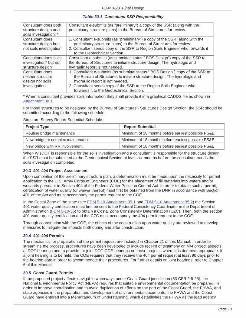
FDM 3-20 Final Design
Page 13
Table 30.1 Consultant SSR Responsibility
Consultant does both structure design and soils investigation. *
Consultant e-submits (as "preliminary") a copy of the SSR (along with the preliminary structure plans) to the Bureau of Structures for review.
Consultant does structure design but not soils investigation.
1. Consultant e-submits (as "preliminary") a copy of the SSR (along with the preliminary structure plans) to the Bureau of Structures for review.
2. Consultant sends copy of the SSR to Region Soils Engineer who forwards it to the Geotechnical Section.
Consultant does soils investigation* but not structure design
Consultant e-submits (as submittal status " BOS Design") copy of the SSR to the Bureau of Structures to initiate structure design. The hydrologic and hydraulic report is not needed.
Consultant does neither structure design nor soils investigation.
1. Consultant e-submits (as submittal status " BOS Design") copy of the SSR to the Bureau of Structures to initiate structure design. The hydrologic and hydraulic report is not needed.
2. Consultant sends copy of the SSR to the Region Soils Engineer who forwards it to the Geotechnical Section.
* When a consultant provides soils information they shall provide it in a graphical CADDS file as shown in Attachment 30.1.
For those structures to be designed by the Bureau of Structures - Structures Design Section, the SSR should be submitted according to the following schedule.
Structure Survey Report Submittal Schedule:
Project Type Report Submittal Routine bridge maintenance Minimum of 18 months before earliest possible PS&E New bridge or complex maintenance Minimum of 18 months before earliest possible PS&E New bridge with RR involvement Minimum of 18 months before earliest possible PS&E
When WisDOT is responsible for the soils investigation and a consultant is responsible for the structure design, the SSR must be submitted to the Geotechnical Section at least six months before the consultant needs the soils investigation completed.
30.3 401-404 Project Assessment Upon completion of the preliminary structure plan, a determination must be made upon the necessity for permit application to the U.S. Army Corps of Engineers (COE) for the placement of fill materials into waters and/or wetlands pursuant to Section 404 of the Federal Water Pollution Control Act. In order to obtain such a permit, certification of water quality (or waiver thereof) must first be obtained from the DNR in accordance with Section 401 of the Act and must accompany the permit request to the COE.
In the Costal Zone of the state (see FDM 5-10 Attachment 35.1 and FDM 5-10 Attachment 35.2) the Section 401 water quality certification must first be sent to the Federal Consistency Coordinator in the Department of Administration (FDM 5-10-35) to obtain a Costal Zone Consistency Determination (CZC). Then, both the section 401 water quality certification and the CZC must accompany the 404 permit request to the COE.
Through coordination with the COE, the effects of the construction upon water quality are reviewed to develop measures to mitigate the impacts both during and after construction.
30.4 401-404 Permits The mechanics for preparation of the permit request are included in Chapter 21 of this Manual. In order to streamline the process, procedures have been developed to include receipt of testimony on 404 project aspects at DOT hearings and to provide for joint DOT-COE hearings on those projects where it is deemed appropriate. If a joint hearing is to be held, the COE requires that they receive the 404 permit request at least 90 days prior to the hearing date in order to accommodate their procedures. For further details on joint hearings, refer to Chapter 6 of this Manual.
30.5 Coast Guard Permits If the proposed project affects navigable waterways under Coast Guard jurisdiction (33 CFR 2.5-25), the National Environmental Policy Act (NEPA) requires that suitable environmental documentation be prepared. In order to improve coordination and to avoid duplication of efforts on the part of the Coast Guard, the FHWA, and state agencies in the preparation and development of environmental documents, the FHWA and the Coast Guard have entered into a Memorandum of Understanding, which establishes the FHWA as the lead agency

FDM 3-20 Final Design
Page 14
and provides for Coast Guard acceptance of all FHWA-prepared environmental documents.
When it has been determined that a proposed project involves a Coast Guard navigable waterway, the following liaison procedures apply:
1. For federal-aid projects for which an EIS or Environmental Assessment (EA) has been prepared [also including 4(f) statements], both the draft and the final are circulated through the Coast Guard for review and comment. These reviews are timed to occur concurrently with the FHWA Division Office reviews.
2. For non-federal-aid projects for which an EIS or EA has been prepared, Coast Guard review for NEPA compliance is still necessary. Therefore, to avoid the potential for a rewrite of the document by the Coast Guard, the project should be cleared for federal aid (through FHWA) whether or not such aid will be ultimately utilized.
Applications for Coast Guard permits are initiated after it has been determined that a navigable waterway will be affected. Copies of the preliminary structure plans are submitted to the Coast Guard by the Bureau of Highway Development along with a letter of application for the permit describing the details of the project and delineating those structural details that will affect navigation--maximum vertical and horizontal clearances, the least clear height with respect to "low steel," etc.
Additionally, as with all federal permits for work that may affect water quality, 401 certification must be obtained from the DNR and, where applicable, the Costal Zone Consistency determination from the DOA before the Coast Guard will issue a permit.
30.6 Railroad Involvement If the structure affects railroad tracks or property, then the general details of the structure design must be approved by the railroad and an agreement specifying the nature and extent of all work established in accordance with the provisions of Section 84.05 of the Wisconsin Statutes. To effect such an agreement, the preliminary structure plan delineating the necessary clearances is provided to the railroad through the Bureau of Railroads & Harbors, along with a proposal of project responsibilities.
The general terms of an agreement are enumerated in a document referred to as a "Stipulation," which is endorsed by the railroad and WisDOT. A copy is presented to the Commissioner of Railroads for information. The Commissioner generally schedules the matter for public hearing and issues an order in accordance with Section 195.29 of the Wisconsin Statutes. If railroad facilities require adjustment to accommodate the project, a final contract, called an "Agreement", is executed by the railroad and WisDOT. This Agreement specifies the work to be done by the railroad and the reimbursement they are to receive for their work. If no railroad facilities require adjustment, or if the railroad is performing such work at its own expense, the "Agreement" is omitted.
As in the case of at-grade crossings, if agreement cannot be reached with the railroad, the matter is referred to the Commissioner of Railroads for resolution in accordance with the provisions of Section 195.29 of the Wisconsin Statutes.
After agreement has been reached, the structure design is still subject to the approval of the FHWA if federal aid is involved in accordance with the provisions of FAPG Part 625.
After railroad comments are received concerning the preliminary structure plan and design disagreements are resolved, the final structure design is prepared by either WisDOT or an approved consultant, as appropriate.
See Chapter 17 for more information on railroad matters.
LIST OF ATTACHMENTS
Attachment 30.1 Sample Soils Information
FDM 3-20-35 Local Road Alterations July 2, 1979
During this phase of the facilities development process it is necessary to finalize all local road alterations necessary for the development of the project.
WisDOT has been vested with the statutory authority to alter local roads at its own discretion, without the specific approval of the local unit involved, in conjunction with designated interstate highways (Section 84.29, Wisconsin Statutes) and/or freeways or expressways (Section 84.295, Wisconsin Statutes). Such local road alterations are approved by the Division Administrator and subsequently filed with the local unit of government. Local road alterations necessitated by improvements to the remainder of the state trunk highway system (all non-84.29- and 84.295-designated highways) require only the approval of the final plans by the Bureau of

WisDOT Bridge Manual
This page intentionally left blank.

WisDOT Bridge Manual Chapter 9 – Materials
July 2016 9-1
Table of Contents
9.1 General .............................................................................................................................. 2
9.2 Concrete ............................................................................................................................ 3
9.3 Reinforcement Bars ........................................................................................................... 4
9.3.1 Development Length and Lap Splices for Deformed Bars ........................................... 5
9.3.2 Bends and Hooks for Deformed Bars ......................................................................... 6
9.3.3 Bill of Bars .................................................................................................................. 7
9.3.4 Bar Series ................................................................................................................... 7
9.4 Steel................................................................................................................................... 9
9.5 Miscellaneous Metals ....................................................................................................... 11
9.6 Timber .............................................................................................................................. 12
9.7 Miscellaneous Materials ................................................................................................... 13
9.8 Painting ............................................................................................................................ 15
9.9 Bar Tables and Figures .................................................................................................... 17
9.10 Granular Materials .......................................................................................................... 24
9.11 References ..................................................................................................................... 25
9.12 Appendix - Draft Bar Tables ........................................................................................... 26

WisDOT Bridge Manual Chapter 9 – Materials
July 2016 9-2
9.1 General
The Wisconsin Standard Specifications for Highway and Structure Construction (hereafter referred to as Standard Specifications) contains references to ASTM Specifications or AASHTO Material Specifications which provide required properties and testing standards for materials used in highway structures. The service life of a structure is dependent upon the quality of the materials used in its construction as well as the method of construction. This chapter highlights applications of materials for highway structures and their properties.
In cases where proprietary products are experimentally specified, special provisions are written which provide material properties and installation procedures. Manufacturer’s recommendations for materials, preparation and their assistance during installation may also be specified.
Materials that are proposed for incorporation into highway structure projects performed under the jurisdiction of the Wisconsin Department of Transportation (WisDOT) may be approved or accepted by a variety of procedures:
• Laboratory testing of materials that are submitted or samples randomly selected.
• Inspection and/or testing at the source of fabrication or manufacture.
• Inspection and/or testing in the field by WisDOT regional personnel.
• Manufacturer’s certificate of compliance and/or manufacturer’s certified report of test or analysis, either as sole documentation for acceptance or as supplemental documentation.
• Inspection, evaluation and testing in the normal course of project administration of material specifications.
• Some products are on approved lists or from fabricators, manufacturers, and certified sources approved by WisDOT. Lists of approved suppliers, products, and certified sources are located at:
http://wisconsindot.gov/Pages/doing-bus/eng-consultants/cnslt-rsrces/tools/appr-prod/default.aspx
The Wisconsin Construction and Materials Manual (CMM) contains a description of procedures for material testing and acceptance requirements in Chapter 8, Section 45. Materials, unless otherwise permitted by the specifications, cannot be incorporated in the project until tested and approved by the proper authority.

WisDOT Bridge Manual Chapter 9 – Materials
July 2016 9-15
9.8 Painting
All highway grade separation structures require steel girders to be painted because unpainted steel is subject to additional corrosion from vehicle salt spray. Additional discussion on painting is presented in Chapter 24 – Steel Girder Structures. The current paint system used for I-girders is the three-coat epoxy system specified in Section 517 of the Standard Specifications. Tub girders utilize a two-coat polysiloxane system, which includes painting of the inside of the tubs.
Recommended standard colors and paint color numbers for steel girders in Wisconsin in accordance with Federal Standard No. 595C as printed are:
White (For Inside of Box Girders) #27925 Blue (Medium Sky Blue Tone) #25240
1 Brown (Similar to Weathering Steel) #20059 Gray ( Light Gray) #26293
Green (Medium Tone) #24260 Reddish-Brown (Red Brick Tone) #20152 Gray (Dark Gray-DNR Request) #26132
Black #27038
Table 9.8-1 Standard Colors for Steel Girders
1 Shop applied color for weathering steel.
Federal Standard No. 595C can be found at www.federalstandardcolor.com/
All steel bearing components which are not welded to the girder or do not have a Teflon or bronze surface, and anchor bolts shall be galvanized. In addition to galvanizing, some bearing components may also be field or shop painted as noted in the Standards for Chapter 27 – Bearings.
All new structural steel is blast cleaned including weathering steel. It has been shown that paint systems perform well over a longer period of time with proper surface preparation. The blast cleaned surface is a very finely pitted surface with pit depths of 1 ½ mils.
Corrosion of structural steel occurs if the agents necessary to form a corrosion cell are present. A corrosion cell is similar to a battery in that current flows from the anode to the cathode. As the current flows, corrosion occurs at the anode and materials expand. Water carries the electrical current between the anode and cathode. If there is salt in the water, the current travels much faster and the rate of corrosion is accelerated. Oxygen combines with the materials to help form the anodic corrosion cell.
The primary reason for painting steel structures is for the protection of the steel surface. Appearance is a secondary function that is maintained by using compatible top coatings over epoxy systems. Regarding appearance with respect to color retention, black is good, blues

WisDOT Bridge Manual Chapter 9 – Materials
July 2016 9-16
and greens are decent, and reddish browns are acceptable, but not the best. Reds are highly discouraged and should not be used.
Paint applied to the steel acts as a moisture barrier. It prevents the water from contacting the steel and then a corrosion cell cannot be formed. When applying a moisture barrier, it is important to get an adhering, uniform thickness as well as an adequate thickness. The film thickness of paint wears with age until it is finally depleted. At this point the steel begins to corrode as moisture is now present in the corrosion cell. If paint is applied too thick, it may crack and/or check due to temperature changes and allow moisture to contact the steel long before the film thickness wears down.
The paint inspector uses a paint gauge to randomly measure the film thickness of the paint according to specifications. Wet film thickness is measured and it is always thicker than the dry film thickness. A vehicle is added to the paint solids so that the solids can be applied to a surface and then it evaporates leaving only the solids on the surface. The percent of solids in a gallon of paint gives an estimate of the wet to dry film thickness ratio.
Refer to Section 1.3.14 of the Wisconsin Structure Inspection Manual for the criteria covering spot painting versus complete painting of existing structures. This Section provides information for evaluating the condition of a paint system and recommended maintenance.
Recommended standard colors and color numbers for concrete in Wisconsin in accordance with Federal Standard No. 595C as printed are:
Pearl Gray #26622 Medium Tan #33446 Gray Green #30372 Dark Brown #30140
Dawn Mist (Grayish Brown) #36424 Lt. Coffee (Creamy Brown) #33722
Table 9.8-2 Standard Colors for Concrete
Most paints require concrete to be a minimum of 30 days old before application. This should be considered when specifying completion times for contracts.

WisDOT Bridge Manual Chapter 9 – Materials
July 2016 9-23
BAR SIZE
BAR WEIGHT
(lbs/ft)
NOM. DIA (in)
NOM. AREA (in2) NUMBER OF BARS
2 3 4 5 6 7 8 9 10
4 0.668 0.500 0.20 0.40 0.60 0.80 1.00 1.20 1.40 1.60 1.80 2.00 5 1.043 0.625 0.31 0.62 0.93 1.24 1.55 1.86 2.17 2.48 2.79 3.10 6 1.502 0.750 0.44 0.88 1.32 1.76 2.20 2.64 3.08 3.52 3.96 4.40 7 2.044 0.875 0.60 1.20 1.80 2.40 3.00 3.60 4.20 4.80 5.40 6.00 8 2.670 1.000 0.79 1.58 2.37 3.16 3.95 4.74 5.53 6.32 7.11 7.90 9 3.400 1.128 1.00 2.00 3.00 4.00 5.00 6.00 7.00 8.00 9.00 10.00
10 4.303 1.270 1.27 2.54 3.81 5.08 6.35 7.62 8.89 10.16 11.43 12.70 11 5.313 1.410 1.56 3.12 4.68 6.24 7.80 9.36 10.92 12.48 14.04 15.60
Table 9.9-3 Bar Areas Per Number of Bars (in2)
BAR SIZE 4 ½“ 5” 5 ½“ 6” 6 ½“ 7” 7 ½” 8” 8 ½” 9” 10” 11” 12”
4 0.52 0.47 0.43 0.39 0.36 0.34 0.31 0.29 0.28 0.26 0.24 0.21 0.20 5 0.82 0.74 0.67 0.61 0.57 0.53 0.49 0.46 0.43 0.41 0.37 0.33 0.31 6 1.18 1.06 0.96 0.88 0.82 0.76 0.71 0.66 0.62 0.59 0.53 0.48 0.44 7 1.60 1.44 1.31 1.20 1.11 1.03 0.96 0.90 0.85 0.80 0.72 0.66 0.60 8 2.09 1.88 1.71 1.57 1.45 1.35 1.26 1.18 1.11 1.05 0.94 0.86 0.79 9 --- 2.40 2.18 2.00 1.85 1.71 1.60 1.50 1.41 1.33 1.20 1.09 1.00
10 --- 3.04 2.76 2.53 2.34 2.17 2.02 1.90 1.79 1.69 1.52 1.38 1.27 11 --- 3.75 3.41 3.12 2.88 2.68 2.50 2.34 2.21 2.08 1.87 1.70 1.56
Table 9.9-4 Area of Bar Reinf. (in2 / ft) vs. Spacing of Bars (in)

WisDOT Bridge Manual Chapter 9 – Materials
July 2016 9-24
9.10 Granular Materials
Several types of granular materials are used for backfilling excavations, providing foundation improvements, and reinforcing soils. Table 9.10-5 provides recommended uses and notes for commonly used granular materials for structures. Refer to the specifications for material gradations, testing, compaction, and other requirements specific for the application. Refer to 6.4.2 for plan preparations.
Granular pay limits should be shown on all structure plans. See Standards for typical backfill limits and plan notes.
Granular Material Type Uses Notes
Backfill Structure – Type A Backfill • Abutments • Retaining walls
Type A facilitates better drainage than Type B. Type A may be substituted for Type B material per specifications. Backfill Structure – Type B
Backfill • Box culverts • Structural plate pipes • Pipe arches Retained Backfill (if needed) Various structures Foundation • Abutments • Retaining walls
Backfill Granular – Grade 1 Refer to FDM for usages
Grade 1 may be substituted for Grade 2 material per specifications. Backfill Granular – Grade 2
Base Aggregate Dense 1 1/4-inch • Structural approach (base) • GRS Walls (reinforced soil
foundation and approach)
Reinforced Soils • MSE Walls Backfill included in MSE Wall bid items.
Base Aggregate Open Graded • GRS Walls (reinforced soil) • MSE Walls (for elevations
below HW100)
Breaker Run • Box culverts (foundation) See Standard Detail 9.01 for alternatives and notes
Flowable Backfill • Soldier pile walls
Table 9.10-5 Recommendations for Granular Material Usage

WisDOT Bridge Manual Chapter 9 – Materials
July 2016 9-25
9.11 References
1. Ghorbanpoor, A., Kriha, B., Reshadi, R. Aesthetic Coating for Steel Bridge Components – Amended Study. S.1.: Wisconsin Department of Transportation, Final Report No. 0092-11-07, 2015.

WisDOT Bridge Manual Chapter 9 – Materials
July 2016 9-26
9.12 Appendix - Draft Bar Tables
The following Draft Bar Tables are provided for information only. We expect the tables to be moved into the main text of Chapter 9 in July of 2017, and at that time to begin their use. We are delaying their use to allow time for modification of details and software that are affected.
The 2015 Interim Revisions to the AASHTO LRFD Bridge Design Specifications (7th Edition), modified the tension development lengths and tension lap lengths for straight deformed bars as follows:
The tension development length, ℓd ,shall not be less than the product of the basic tension development length, ℓdb , and the appropriate modification factors, λi . LRFD [5.11.2.1.1]
ℓd = ℓdb · (λrl · λcf · λIw ·λrc · λer )
in which: ℓdb = 2.4 · db · [fy / (f’c)1/2]
where:
ℓdb = basic development length (in.)
λrl = reinforcement location factor
λcf = coating factor
λIw = lightweight concrete factor
λrc = reinforcement confinement factor
λer = excess reinforcement factor
fy = specified yield strength of reinforcing bars (ksi)
db = diameter of bar (in.)
f’c = specified compressive strength of concrete (ksi)
Top bars will continue to refer to horizontal bars placed with more than 12” of fresh concrete cast below it. Bars not meeting this criteria will be referred to as Others.
Per LRFD [5.11.5.3.1], there are two lap splice classes, Class A and Class B.
• Class A lap splice ……………………1.0 ℓd
• Class B lap splice …………………... 1.3 ℓd
The criteria for where to apply each Class is covered in the above reference.

WisDOT Bridge Manual Chapter 11 – Foundation Support
July 2016 11-1
Table of Contents
11.1 General ............................................................................................................................ 4
11.1.1 Overall Design Process ............................................................................................ 4
11.1.2 Foundation Type Selection ....................................................................................... 4
11.1.3 Cofferdams ............................................................................................................... 6
11.1.4 Vibration Concerns ................................................................................................... 6
11.2 Shallow Foundations ........................................................................................................ 8
11.2.1 General..................................................................................................................... 8
11.2.2 Footing Design Considerations ................................................................................. 8
11.2.2.1 Minimum Footing Depth .................................................................................... 8
11.2.2.1.1 Scour Vulnerability ..................................................................................... 9
11.2.2.1.2 Frost Protection ......................................................................................... 9
11.2.2.1.3 Unsuitable Ground Conditions ................................................................. 10
11.2.2.2 Tolerable Movement of Substructures Founded on Shallow foundations ........ 10
11.2.2.3 Location of Ground Water Table ..................................................................... 11
11.2.2.4 Sloping Ground Surface .................................................................................. 11
11.2.3 Settlement Analysis ................................................................................................ 11
11.2.4 Overall Stability ....................................................................................................... 12
11.2.5 Footings on Engineered Fills .................................................................................. 13
11.2.6 Construction Considerations ................................................................................... 14
11.2.7 Geosynthetic Reinforced Soil (GRS) Abutment ....................................................... 14
11.3 Deep Foundations .......................................................................................................... 15
11.3.1 Driven Piles ............................................................................................................ 15
11.3.1.1 Conditions Involving Short Pile Lengths .......................................................... 15
11.3.1.2 Pile Spacing .................................................................................................... 16
11.3.1.3 Battered Piles.................................................................................................. 17
11.3.1.4 Corrosion Loss ................................................................................................ 17
11.3.1.5 Pile Points ....................................................................................................... 17
11.3.1.6 Preboring ........................................................................................................ 18
11.3.1.7 Seating............................................................................................................ 18
11.3.1.8 Pile Embedment in Footings ........................................................................... 18
11.3.1.9 Pile-Supported Footing Depth ......................................................................... 19
11.3.1.10 Splices .......................................................................................................... 19

WisDOT Bridge Manual Chapter 11 – Foundation Support
July 2016 11-2
11.3.1.11 Painting ......................................................................................................... 19
11.3.1.12 Selection of Pile Types .................................................................................. 19
11.3.1.12.1 Timber Piles .......................................................................................... 20
11.3.1.12.2 Concrete Piles ....................................................................................... 21
11.3.1.12.2.1 Driven Cast-In-Place Concrete Piles .............................................. 21 11.3.1.12.2.2 Precast Concrete Piles ................................................................... 23
11.3.1.12.3 Steel Piles ............................................................................................. 24
11.3.1.12.3.1 H-Piles ........................................................................................... 24 11.3.1.12.3.2 Oil Field Piles ................................................................................. 25
11.3.1.12.4 Pile Bents .............................................................................................. 26
11.3.1.13 Tolerable Movement of Substructures Founded on Driven Piles ................... 26
11.3.1.14 Resistance Factors ....................................................................................... 26
11.3.1.15 Bearing Resistance ....................................................................................... 28
11.3.1.15.1 Shaft Resistance ................................................................................... 29
11.3.1.15.2 Point Resistance.................................................................................... 32
11.3.1.15.3 Group Capacity ..................................................................................... 33
11.3.1.16 Lateral Load Resistance................................................................................ 33
11.3.1.17 Other Design Considerations ........................................................................ 34
11.3.1.17.1 Downdrag Load ..................................................................................... 34
11.3.1.17.2 Lateral Squeeze .................................................................................... 35
11.3.1.17.3 Uplift Resistance.................................................................................... 35
11.3.1.17.4 Pile Setup and Relaxation ..................................................................... 35
11.3.1.17.5 Drivability Analysis ................................................................................. 36
11.3.1.17.6 Scour ..................................................................................................... 40
11.3.1.17.7 Typical Pile Resistance Values .............................................................. 40
11.3.1.18 Construction Considerations ......................................................................... 43
11.3.1.18.1 Pile Hammers ........................................................................................ 43
11.3.1.18.2 Driving Formulas ................................................................................... 44
11.3.1.18.3 Field Testing .......................................................................................... 46
11.3.1.18.3.1 Installation of Test Piles ................................................................. 46 11.3.1.18.3.2 Static Pile Load Tests .................................................................... 46
11.3.1.19 Construction Monitoring for Economic Evaluation of Deep Foundations ........ 47
11.3.2 Drilled Shafts .......................................................................................................... 50
11.3.2.1 General ........................................................................................................... 50

WisDOT Bridge Manual Chapter 11 – Foundation Support
July 2016 11-3
11.3.2.2 Resistance Factors ......................................................................................... 51
11.3.2.3 Bearing Resistance ......................................................................................... 53
11.3.2.3.1 Point Resistance ..................................................................................... 54
11.3.2.3.2 Group Capacity ....................................................................................... 54
11.3.2.4 Lateral Load Resistance ................................................................................. 54
11.3.2.5 Other Considerations ...................................................................................... 54
11.3.3 Micropiles ............................................................................................................... 55
11.3.3.1 General ........................................................................................................... 55
11.3.3.2 Design Guidance ............................................................................................ 55
11.3.4 Augered Cast-In-Place Piles ................................................................................... 55
11.3.4.1 General ........................................................................................................... 55
11.3.4.2 Design Guidance ............................................................................................ 56
11.4 References ..................................................................................................................... 57
11.5 Design Examples ........................................................................................................... 59

WisDOT Bridge Manual Chapter 11 – Foundation Support
July 2016 11-4
11.1 General
11.1.1 Overall Design Process
The overall foundation support design process requires an iterative collaboration to provide cost-effective constructible substructures. Input is required from multiple disciplines including, but not limited to, structural, geotechnical and design. For a typical bridge design, the following four steps are required (see 6.2):
1. Structure Survey Report (SSR) – This design step results in a very preliminary evaluation of the structure type and approximate location of substructure units, including a preliminary layout plan.
2. Site Investigation Report – Based on the Structure Survey Report, a Geotechnical Investigation (see Chapter 10 – Geotechnical Investigation) is required, including test borings to determine foundation requirements. A hydraulic analysis is also performed at this time, if required, to assess scour potential and maximum scour depth. The Site Investigation Report and Subsurface Exploration Drawing are used to identify known constraints that would affect the foundations in regard to type, location or size and includes foundation recommendations to support detailed structural design. Certain structure sites/types may require the preliminary structure plans (Step 3) prior to initiating the geotechnical site investigation. One example of this is a multi-span structure over water. See 6.2 for more information.
3. Preliminary Structure Plans – This design step involves preparation of a general plan, elevation, span arrangement, typical section and cost estimate for the new bridge structure. The Site Investigation Report is used to identify possible poor foundation conditions and may require modification of the structure geometry and span arrangement. This step may require additional geotechnical input, especially if substructure locations must be changed.
4. Final Contract Plans for Structures – This design step culminates in final plans, details, special provisions and cost estimates for construction. The Subsurface Exploration sheet(s) are part of the Final Contract Plans. Unless design changes are required at this step, additional geotechnical input is not typically required to prepare foundation details for the Final Contract Plans.
11.1.2 Foundation Type Selection
The following items need to be assessed to select site-specific foundation types:
• Magnitude and direction of loads.
• Depth to suitable bearing material.
• Potential for liquefaction, undermining or scour.
• Frost potential.

WisDOT Bridge Manual Chapter 11 – Foundation Support
July 2016 11-25
maximum axial resistance is required by design, state only the required corresponding driving resistance on the plans.
Since granular soil is largely incompressible, the principal action at the tip of the pile is lateral displacement of soil particles. Although it is an accepted fact that steel piles develop extremely high loads per pile when driven to point-bearing on rock, some misconceptions still remain that H-piles cannot function as friction piles. Load tests indicate that steel H-piles can function quite satisfactorily as friction piles in sand, sand-clay, silt-and-sand or hard clay. However, they are not as efficient as displacement piles in these conditions and typically drive to greater depths. The surface area for pile frictional computations is considered to be the projected “box area” of the H-pile, and not the actual steel surface area.
Clay is compressible to a far greater degree than sand or gravel. As the solid particles are pressed into closer contact with each other and water is squeezed out of the voids, only small frictional resistance to driving is generated because of the lubricating action of the free water. However, after driving is completed, the lateral pressure against the pile increases due to dissipation of the pore water pressures. This causes the fine clay particles to increase adherence to the comparatively rough surface of the pile. Load is transferred from the pile to the soil by the resulting strong adhesive bond. In many types of clay, this bond is stronger than the shearing resistance of the soil.
In hard, stiff clays containing a low percentage of voids and pore water, the compressibility is small. As a result, the amount of displacement and compression required to develop the pile’s full capacity are correspondingly small. As an H-pile is driven into stiff clay, the soil trapped between the flanges and web usually becomes very hard due to the compression and is carried down with it. This trapped soil acts as a plug and the pile can also act as a displacement pile.
In cases where loose soil is encountered, considerably longer point-bearing steel piles are required to carry the same load as relatively short displacement-type piles. This is because a displacement-type pile, with its larger cross section, produces more compaction as it is driven through materials such as soft clays or loose organic silts. H-piles are not typically used in exposed pile bents due to concerns with debris catchment.
11.3.1.12.3.2 Pipe Piles
Pipe piles consist of seamless, welded or spiral welded steel pipes in diameters ranging from 7-3/4 to 24 inches. Other sizes are available, but they are not commonly used. Typical wall thicknesses range from 0.375-inch to 0.75-inch, with wall thicknesses of up to 1.5 inches possible. Pipe piles should be specified by grade with reference to ASTM A 252.
Pipe piles may be driven either open or closed end. If the end bearing capacity from the full pile toe area is required, the pile toe should be closed with a flat plate or a conical tip.
11.3.1.12.3.3 Oil Field Piles
The oil industry uses a very high quality pipe in their drilling operations. Every piece is tested for conformance to their standards. Oil field pipe is accepted as a point-bearing alternative to HP piling, provided the material in the pipe meets the requirements of ASTM A 252, Grade 3,

WisDOT Bridge Manual Chapter 11 – Foundation Support
July 2016 11-26
with a minimum tensile strength of 120 ksi or a Brinell Hardness Number (BHN) of 240, a minimum outside diameter of 7-3/4 inches and a minimum wall thickness of 0.375-inch. The weight and area of the pipe shall be approximately the same as the HP piling it replaces. Sufficient bending strength shall be provided if the oil field pipe is replacing HP piling in a pile bent. Oil field pipe is driven open-ended and not filled with concrete. The availability of this pile type varies and is subject to changes in the oil industry.
11.3.1.12.4 Pile Bents
See 13.1 for criteria to use pile bents at stream crossings. When pile bents fail to meet these criteria, pile-encased pier bents should be considered. To improve debris flow, round piles are generally selected for exposed bents. Round or H-piles can be used for encased bents.
11.3.1.13 Tolerable Movement of Substructures Founded on Driven Piles
WisDOT policy item:
For design of new bridge structures founded on driven piles, limit the horizontal movement at the top of the foundation unit to 0.5 inch or less at the service limit state.
11.3.1.14 Resistance Factors
The nominal (ultimate) geotechnical resistance capacity of the pile should be based on the type, depth and condition of subsurface material and ground water conditions reported in the Geotechnical Site Investigation Report, as well as the method of analysis used to determine pile resistance. Resistance factors to compute the factored geotechnical resistance are presented in LRFD [Table 10.5.5.2.3-1] and are selected based on the method used to determine the nominal (ultimate) axial compression resistance. The design intent is to adjust the resistance factor based on the reliability of the method used to determine the nominal pile resistance. When construction controls, are used to improve the reliability of capacity prediction (such as pile driving analyzer or static load tests), the resistance factors used during final design should be increased in accordance with LRFD [Table 10.5.5.2.3-1] to reflect planned construction monitoring.
WisDOT exception to AASHTO:
WisDOT requires at least four (4) piles per group to support each substructure unit, including each column for multi-column bents. WisDOT does not reduce geotechnical resistance factors to satisfy redundancy requirements to determine axial pile resistance. Hence, redundancy resistance factors in LRFD [10.5.5.2.3] are not applicable to WisDOT structures. This exception applies to typical CIP concrete pile and H-pile foundations. Non-typical foundations (such as drilled shafts) shall be investigated individually.
No guidance regarding the structural design of non-redundant driven pile groups is currently included in AASHTO LRFD. Since WisDOT requires a minimum of 4 piles per substructure unit, structural design should be based on a load modifier, η, of 1.0. Further description of load modifiers is presented in LRFD [1.3.4].

WisDOT Bridge Manual Chapter 11 – Foundation Support
July 2016 11-27
The following geotechnical resistance factors apply to the majority of the Wisconsin bridges that are founded on driven pile. On the majority of WisDOT projects, wave equation analysis and dynamic monitoring are not used to set driving criteria. This equates to typical resistance factors of 0.35 to 0.45 for pile design. A summary of resistance factors is presented in Table 11.3-1, which are generally used for geotechnical design on WisDOT projects.
Condition/Resistance Determination Method Resistance Factor
Stat
ic A
naly
sis
– U
sed
in D
esig
n Ph
ase
Nominal Resistance of Single Pile in
Axial Compression,
ϕstat
Skin Friction and End Bearing in Clay and Mixed Soil Alpha Method 0.35
Skin Friction and End Bearing in Sand Nordlund/Thurman Method 0.45
Point Bearing in Rock 0.45 Block Failure,
ϕbl Clay 0.60
Uplift Resistance of Single Pile,
ϕup
Clay and Mixed Soil Alpha Method
0.25
Sand Nordlund Method
0.35
Horizontal Resistance of Single Pile or
Pile Group
All Soil Types and Rock 1.0
Nominal Resistance of Single Pile in Axial
Compression – Dynamic Analysis – for the Hammer and Pile Driving System
Actually - used During Construction for Pile
Installation, ϕdyn
FHWA-modified Gates dynamic pile driving formula (end of drive condition only) 0.50
Wave equation analysis, without pile dynamic measurements or load test, at end of drive condition only 0.50
Driving criteria established by dynamic test with signal matching at beginning of redrive conditions only of at least one production pile per substructure, but no less
than the number of tests per site provided in LRFD [Table 10.5.5.2.3-3]; quality control of remaining piles by
calibrated wave equation and/or dynamic testing
0.65
Table 11.3-1 Geotechnical Resistance Factors for Driven Pile
Resistance factors for structural design of piles are based on the material used, and are presented in the following sections of AASHTO LRFD:
• Concrete piles – LRFD [5.5.4.2.1]
• Steel piles – LRFD [6.5.4.2]

WisDOT Bridge Manual Chapter 11 – Foundation Support
July 2016 11-28
11.3.1.15 Bearing Resistance
A pile foundation transfers load into the underlying strata by either shaft resistance, point resistance or a combination of both. Any driven pile will develop some amount of both shaft and point resistance. However, a pile that receives the majority of its support capacity by friction or adhesion from the soil along its shaft is referred to as a friction pile, whereas a pile that receives the majority of its support from the resistance of the soil near its tip is a point resistance (end bearing) pile.
The design pile capacity is the maximum load the pile can support without exceeding the allowable movement criteria. When considering design capacity, one of two items may govern the design – the nominal (ultimate) geotechnical resistance capacity or the structural resistance capacity of the pile section. This section focuses primarily on the geotechnical resistance capacity of a pile.
The factored load that is applied to a single pile is carried jointly by the soil beneath the tip of the pile and by the soil around the shaft. The total factored load is not permitted to exceed the factored resistance of the pile foundation for each limit state in accordance with LRFD [1.3.2.1 and 10.7.3.8.6]. The factored bearing resistance, or pile capacity, of a pile is computed as follows:
sstatpstatnriii RRRRQ ϕ+ϕ=ϕ=≤γη∑
Where:
iη = Load modifier
iγ = Load factor
iQ = Force effect (tons)
Rr = Factored bearing resistance of pile (tons)
Rn = Nominal resistance (tons)
Rp = Nominal point resistance of pile (tons)
Rs = Nominal shaft resistance of pile (tons)
ϕ = Resistance factor
ϕstat = Resistance factor for driven pile, static analysis method
This equation is illustrated in Figure 11.3-1.

WisDOT Bridge Manual Chapter 11 – Foundation Support
July 2016 11-29
Figure 11.3-1 Resistance Distribution for Axially-Loaded Pile
11.3.1.15.1 Shaft Resistance
The shaft resistance of a pile is estimated by summing the frictional resistance developed in each of the different soil strata.
For non-cohesive (granular) soil, the total shaft resistance can be calculated using the following equation (based on the Nordlund/Thurman Method):

WisDOT Bridge Manual Chapter 11 – Foundation Support
July 2016 11-30
( )( )ω
ω+δσΣ= δ cos
sin'CKDCR vFds
Where:
Rs = Total shaft resistance capacity (tons)
Cd = Pile perimeter (feet)
D = Pile segment length (feet)
Kδ = Coefficient of lateral earth pressure at mid-point of soil layer under consideration from LRFD [Figures 10.7.3.8.6f-1 through 10.7.3.8.6f-4]
CF = Correction factor for Kδ when δ ≠ φf , from LRFD [Figure 10.7.3.8.6f-5], whereby φf = angle of internal friction for drained soil
σv’ = Effective overburden pressure at midpoint of soil layer under consideration (tsf)
δ = Friction angle between the pile and soil obtained from LRFD [Figure 10.7.3.8.6f-6] (degrees)
ω = Angle of pile taper from vertical (degrees)
For cohesive (fine-grained) soil, the total shaft resistance can be calculated using the following equation (based on the alpha method):
DCSR dus αΣ=
Where:
Rs = Total (nominal) shaft resistance capacity (tons)
α = Adhesion factor based on the undrained shear strength from LRFD [Figure 10.7.3.8.6b-1]
Su = Undrained shear strength (tsf)
Cd = Pile perimeter (feet)
D = Pile segment length (feet)
Typical values of nominal shaft resistance for various soils are presented in Table 11.3-2 and Table 11.3-3. The values presented are average ranges and are intended to provide orders of magnitude only. Other conditions such as layering sequences, drilling information, ground water, thixotropy and clay sensitivity must be evaluated by experienced geotechnical engineers and analyzed using principles of soil mechanics.

WisDOT Bridge Manual Chapter 11 – Foundation Support
July 2016 11-31
Soil Type qu
(1) (tsf)
Nominal Shaft Resistance
(psf) Very soft clay 0 to 0.25 ---
Soft clay 0.25 to 0.5 200 to 450 Medium clay 0.5 to 1.0 450 to 800
Stiff clay 1.0 to 2.0 800 to 1,500 Very stiff clay 2.0 to 4.0 1,500 to 2,500
Hard clay 4.0 2,500 to 3,500 Silt --- 100 to 400
Silty clay --- 400 to 700 Sandy clay --- 400 to 700 Sandy silt --- 600 to 1,000
Dense silty clay --- 900 to 1,500
(1) Unconfined Compression Strength
Table 11.3-2 Typical Nominal Shaft Resistance Values for Cohesive Material
Soil Type N160(1)
Nominal Shaft Resistance
(psf) Very loose sand and silt or clay 0 to 6 50 to 150
Medium sand and silt or clay 6 to 30 400 to 600 Dense sand and silt or clay 30 to 50 600 to 800
Very dense sand and silt or clay over 50 800 to 1,000 Very loose sand 0 to 4 700 to 1,700
Loose sand 4 to 10 700 to 1,700 Firm sand 10 to 30 700 to 1,700
Dense sand 30 to 50 700 to 1,700 Very dense sand over 50 700 to 1,700 Sand and gravel --- 1,000 to 3,000
Gravel --- 1,500 to 3,500

WisDOT Bridge Manual Chapter 11 – Foundation Support
July 2016 11-32
(1) Standard Penetration Value (AASHTO T206) corrected for both overburden and hammer efficiency effects (blows per foot).
Table 11.3-3 Typical Nominal Shaft Resistance Values for Granular Material
Shaft resistance values are dependent upon soil texture, overburden pressure and soil cohesion but tend to increase with depth. However, experience in Wisconsin has shown that shaft resistance values in non-cohesive materials reach constant final values at depths of 15 to 25 pile diameters in loose sands and 25 to 35 pile diameters in firm sands.
In computing shaft resistance, the method of installation must be considered as well as the soil type. The method of installation significantly affects the degree of soil disturbance, the lateral stress acting on the pile, the friction angle and the area of contact. Shafts of prebored piles do not always fully contact the soil; therefore, the effective contact area is less than the shaft surface area. Driving a pile in granular material densifies the soil and increases the friction angle. Driving also displaces the soil laterally and increases the horizontal stress acting on the pile. Disturbance of clay soil from driving can break down soil structure and increase pore pressures, which greatly decreases soil strength. However, some or all of the strength recovers following reconsolidation of the soil due to a decrease in excess pore pressure over time. Use the initial soil strength values for design purposes. The type and shape of a pile also affects the amount of shaft resistance developed, as described in 11.3.1.12.
11.3.1.15.2 Point Resistance
The point resistance, or end bearing capacity, of a pile is estimated from modifications to the bearing capacity formulas developed for shallow footings.
For non-cohesive soils, point resistance can be calculated using the following equation (based on the Nordlund/Thurman Method):
pLvqtpp Aq''NAR ≤σα=
Where:
Rp = Point resistance capacity (tons)
Ap = Pile end area (feet2)
αt = Dimensionless factor dependent on depth-width relationship from LRFD [Figure 10.7.3.8.6f-7]
N’q = Bearing capacity factor from LRFD [Figure 10.7.3.8.6f-8]
σv’ = Effective overburden pressure at the pile point ≤ 1.6 (tsf)
qL = Limiting unit point resistance from LRFD [Figure 10.7.3.8.6f-9] (tsf)

WisDOT Bridge Manual Chapter 12 – Abutments
July 2016 12-1
Table of Contents
12.1 General ............................................................................................................................ 3
12.2 Abutment Types ............................................................................................................... 5
12.2.1 Full-Retaining ........................................................................................................... 5
12.2.2 Semi-Retaining ......................................................................................................... 6
12.2.3 Sill ............................................................................................................................ 7
12.2.4 Spill-Through or Open .............................................................................................. 7
12.2.5 Pile-Encased ............................................................................................................ 8
12.2.6 Special Designs ........................................................................................................ 8
12.3 Types of Abutment Support .............................................................................................. 9
12.3.1 Piles or Drilled Shafts ............................................................................................... 9
12.3.2 Spread Footings ..................................................................................................... 10
12.4 Abutment Wing Walls ..................................................................................................... 11
12.4.1 Wing Wall Length ................................................................................................... 11
12.4.1.1 Wings Parallel to Roadway ............................................................................. 11
12.4.1.2 Wings Not Parallel to Roadway and Equal Slopes .......................................... 12
12.4.2 Wing Wall Loads ..................................................................................................... 14
12.4.3 Wing Wall Parapets ................................................................................................ 15
12.5 Abutment Depths, Excavation and Construction............................................................. 16
12.5.1 Abutment Depths .................................................................................................... 16
12.5.2 Abutment Excavation .............................................................................................. 16
12.6 Abutment Drainage and Backfill ..................................................................................... 18
12.6.1 Abutment Drainage ................................................................................................. 18
12.6.2 Abutment Backfill Material ...................................................................................... 18
12.7 Selection of Standard Abutment Types .......................................................................... 19
12.8 Abutment Design Loads and Other Parameters ............................................................. 22
12.8.1 Application of Abutment Design Loads ................................................................... 22
12.8.2 Load Modifiers and Load Factors ........................................................................... 25
12.8.3 Live Load Surcharge............................................................................................... 26
12.8.4 Other Abutment Design Parameters ....................................................................... 27
12.8.5 Abutment and Wing Wall Design in Wisconsin........................................................ 28
12.8.6 Horizontal Pile Resistance ...................................................................................... 29
12.9 Abutment Body Details ................................................................................................... 30

WisDOT Bridge Manual Chapter 12 – Abutments
July 2016 12-2
12.9.1 Construction Joints ................................................................................................. 30
12.9.2 Beam Seats ............................................................................................................ 31
12.10 Timber Abutments ........................................................................................................ 33
12.11 Bridge Approach Design and Construction Practices ................................................... 34
WisDOT Bridge Manual Chapter 12 – Abutments
July 2016 12-17
removed by the roadway contractor. A semi-retaining or full-retaining abutment placed on fill is considered a unique problem by the design engineer, and limits of excavation must be set accordingly. Construction sequence and type of fill material are considered when setting excavation limits. Slopes greater than 1.5 horizontal to 1 vertical are difficult to construct and generally are not specified. It is sometimes advantageous to have the roadway contractor place extra fill that later must be excavated by the bridge contractor, because the overburden aids in compaction and reduces subsequent settlement.
Lateral limits of excavation are not defined in the Standard Specifications. The contractor must excavate whatever is necessary within the right-of-way for the placement of the forms.

WisDOT Bridge Manual Chapter 12 – Abutments
July 2016 12-18
12.6 Abutment Drainage and Backfill
This section describes abutment design considerations related to drainage and backfill. The abutment drainage and backfill must be designed and detailed properly to prevent undesirable loads from being applied to the abutment.
12.6.1 Abutment Drainage
Abutment drainage is necessary to prevent hydrostatic pressure and frost pressure. Hydrostatic pressure, including both soil and water, can amount to an equivalent fluid unit weight of soil of 85 pcf. Frost action, which can occur in silty backfill, may result in extremely high pressures. On high abutments, these pressures will produce a very large force which could result in structural damage or abutment movement if not accounted for in the design.
To prevent these additional pressures on abutments, it is necessary to drain away whatever water accumulates behind the body and wings. This is accomplished using a pervious granular fill on the inside face of the abutment. Pipe underdrain must be provided to drain the fill located behind the abutment body and wings. For rehabilitation of structures, provide plan details to replace inadequate underdrain systems.
Past experience indicates that sill abutments are not capable of withstanding hydrostatic pressure on their full height without leaking.
Semi-retaining and full-retaining abutments generally will be overstressed or may slide if subject to large hydrostatic or frost pressures unless accounted for in the design. Therefore, “Pipe Underdrain Wrapped 6-inch” is required behind all abutments. This pipe underdrain is used behind the abutment and outside the abutment to drain the water away. It is best to place the pipe underdrain at the bottom of footing elevation as per standards. However, if it is not possible to discharge the water to a lower elevation, the pipe underdrain should be placed higher.
Pipe underdrains and weepholes may discharge water during freezing temperatures. In urban areas, this may create a problem due to the accumulation of flow and ice on sidewalks.
12.6.2 Abutment Backfill Material
All abutments and wings shall utilize “Backfill Structure” to facilitate drainage. See Standard Detail 9.01 – Structure Backfill Limits and Notes – for typical pay limits and plan notes.

WisDOT Bridge Manual Chapter 12 – Abutments
July 2016 12-19
12.7 Selection of Standard Abutment Types
From past experience and investigations, the abutment types presented in Figure 12.7-1 are generally most suitable and economical for the given conditions. Although piles are shown for each abutment type, drilled shafts or spread footings may also be utilized depending on the material conditions at the bridge site. The chart in Figure 12.7-1 provides a recommended guide for abutment type selection.

WisDOT Bridge Manual Chapter 12 – Abutments
July 2016 12-20
Figure 12.7-1 Recommended Guide for Abutment Type Selection

WisDOT Bridge Manual Chapter 13 – Piers
July 2016 13-1
Table of Contents
13.1 General ............................................................................................................................ 3
13.1.1 Pier Type and Configuration ..................................................................................... 3
13.1.2 Bottom of Footing Elevation ...................................................................................... 4
13.1.3 Pier Construction ...................................................................................................... 4
13.2 Pier Types ........................................................................................................................ 5
13.2.1 Multi-Column Piers ................................................................................................... 5
13.2.2 Pile Bents ................................................................................................................. 6
13.2.3 Pile Encased Piers ................................................................................................... 7
13.2.4 Solid Single Shaft / Hammerheads ........................................................................... 8
13.2.5 Aesthetics ................................................................................................................. 8
13.3 Location ........................................................................................................................... 9
13.4 Loads on Piers ............................................................................................................... 10
13.4.1 Dead Loads ............................................................................................................ 10
13.4.2 Live Loads .............................................................................................................. 10
13.4.3 Vehicular Braking Force ......................................................................................... 11
13.4.4 Wind Loads ............................................................................................................ 11
13.4.4.1 Wind Load on Superstructure .......................................................................... 12
13.4.4.2 Wind Load Applied Directly to Substructure .................................................... 13
13.4.4.3 Wind Load on Vehicles ................................................................................... 13
13.4.4.4 Vertical Wind Load .......................................................................................... 13
13.4.5 Uniform Temperature Forces .................................................................................. 13
13.4.6 Force of Stream Current ......................................................................................... 16
13.4.6.1 Longitudinal Force .......................................................................................... 16
13.4.6.2 Lateral Force ................................................................................................... 16
13.4.7 Buoyancy ................................................................................................................ 17
13.4.8 Ice .......................................................................................................................... 18
13.4.8.1 Force of Floating Ice and Drift ......................................................................... 18
13.4.8.2 Force Exerted by Expanding Ice Sheet ........................................................... 19
13.4.9 Centrifugal Force .................................................................................................... 20
13.4.10 Extreme Event Collision Loads ............................................................................. 20
13.5 Load Application............................................................................................................. 22

WisDOT Bridge Manual Chapter 13 – Piers
July 2016 13-2
13.5.1 Loading Combinations ............................................................................................ 22
13.5.2 Expansion Piers ...................................................................................................... 22
13.5.3 Fixed Piers ............................................................................................................. 23
13.6 Multi-Column Pier and Cap Design ................................................................................ 24
13.7 Hammerhead Pier Cap Design ....................................................................................... 25
13.7.1 Draw the Idealized Truss Model ............................................................................. 26
13.7.2 Solve for the Member Forces .................................................................................. 27
13.7.3 Check the Size of the Bearings ............................................................................... 28
13.7.4 Design Tension Tie Reinforcement ......................................................................... 29
13.7.5 Check the Compression Strut Capacity .................................................................. 30
13.7.6 Check the Tension Tie Anchorage .......................................................................... 33
13.7.7 Provide Crack Control Reinforcement ..................................................................... 33
13.8 General Pier Cap Information ......................................................................................... 34
13.9 Column / Shaft Design ................................................................................................... 36
13.10 Pile Bent and Pile Encased Pier Analysis ..................................................................... 38
13.11 Footing Design ............................................................................................................. 39
13.11.1 General Footing Considerations ........................................................................... 39
13.11.2 Isolated Spread Footings ...................................................................................... 40
13.11.3 Isolated Pile Footings ........................................................................................... 42
13.11.4 Continuous Footings ............................................................................................. 44
13.11.5 Cofferdams and Seals .......................................................................................... 45
13.12 Quantities ..................................................................................................................... 48
13.13 Design Examples ......................................................................................................... 49

WisDOT Bridge Manual Chapter 13 – Piers
July 2016 13-47
Example: Determine the seal thickness for a 9’ x 12’ footing with 12-12” diameter piles. Uplift capacity of one pile equals 15 kips (per the Geotechnical Engineer). The water depth to the top of seal is 16’.
Assume 15’ x 18’ x 3.25’ seal.
Figure 13.11-4 Seal Inside a Cofferdam
Uplift force of water 15 x 18 x 19.25 x 0.0624 = 324.3 kips (up) Weight of seal course 15 x 18 x 3.25 x 0.15 = 131.6 kips (down)
Friction of sheet piling 2 x (15+18) x (3.25 - 2.0) x 144 x 0.002
= 23.8 kips (down)
Pile frictional resistance π x 12 x (3.25 x 12) x 0.010 = 14.7 kips
Pile uplift resistance (Per Geotechnical Engineer) = 15.0 kips Total pile resistance 12 piles x min(14.7,15.0) = 176.4 kips (down) Sum of downward forces 131.6+23.8+176.4 = 332 kips Sum of upward forces 324.3 = 324 kips
332 > 324 OK
USE 3’- 3” THICK SEAL Note: Pile uplift resistance shall be determine by the Geotechnical Engineer. For this example, when the pile uplift resistance equals 10 kips a 4’-6” thick seal is required.

WisDOT Bridge Manual Chapter 13 – Piers
July 2016 13-48
13.12 Quantities
Consider the "Upper Limits for Excavation" for piers at such a time when the quantity is a minimum. This is either at the existing ground line or the finished graded section. Indicate in the general notes which value is used.
Structure backfill is not used at piers except under special conditions.
Compute the concrete quantities for the footings, columns and cap, and show values for each of them on the final plans.

WisDOT Bridge Manual Chapter 14 – Retaining Walls
July 2016 14-1
Table of Contents
14.1 Introduction ...................................................................................................................... 7
14.1.1 Wall Development Process ....................................................................................... 7
14.1.1.1 Wall Numbering System .................................................................................... 8
14.2 Wall Types ..................................................................................................................... 10
14.2.1 Gravity Walls .......................................................................................................... 11
14.2.1.1 Mass Gravity Walls ......................................................................................... 11
14.2.1.2 Semi-Gravity Walls ......................................................................................... 11
14.2.1.3 Modular Gravity Walls ..................................................................................... 12
14.2.1.3.1 Modular Block Gravity Walls .................................................................... 12
14.2.1.3.2 Prefabricated Bin, Crib and Gabion Walls ................................................ 12
14.2.1.4 Rock Walls ...................................................................................................... 13
14.2.1.5 Mechanically Stabilized Earth (MSE) Walls: .................................................... 13
14.2.1.6 Soil Nail Walls ................................................................................................. 13
14.2.2 Non-Gravity Walls ................................................................................................... 15
14.2.2.1 Cantilever Walls .............................................................................................. 15
14.2.2.2 Anchored Walls ............................................................................................... 15
14.2.3 Tiered and Hybrid Wall Systems ............................................................................. 16
14.2.4 Temporary Shoring ................................................................................................. 17
14.2.5 Wall Classification Chart ......................................................................................... 17
14.3 Wall Selection Criteria .................................................................................................... 20
14.3.1 General................................................................................................................... 20
14.3.1.1 Project Category ............................................................................................. 20
14.3.1.2 Cut vs. Fill Application ..................................................................................... 20
14.3.1.3 Site Characteristics ......................................................................................... 21
14.3.1.4 Miscellaneous Design Considerations ............................................................. 21
14.3.1.5 Right of Way Considerations ........................................................................... 21
14.3.1.6 Utilities and Other Conflicts ............................................................................. 22
14.3.1.7 Aesthetics ....................................................................................................... 22
14.3.1.8 Constructability Considerations ....................................................................... 22
14.3.1.9 Environmental Considerations ........................................................................ 22
14.3.1.10 Cost .............................................................................................................. 22
14.3.1.11 Mandates by Other Agencies ........................................................................ 23

WisDOT Bridge Manual Chapter 14 – Retaining Walls
July 2016 14-2
14.3.1.12 Requests made by the Public ........................................................................ 23
14.3.1.13 Railing ........................................................................................................... 23
14.3.1.14 Traffic barrier ................................................................................................. 23
14.3.2 Wall Selection Guide Charts ................................................................................... 23
14.4 General Design Concepts .............................................................................................. 26
14.4.1 General Design Steps ............................................................................................. 26
14.4.2 Design Standards ................................................................................................... 27
14.4.3 Design Life ............................................................................................................. 27
14.4.4 Subsurface Exploration ........................................................................................... 27
14.4.5 Load and Resistance Factor Design Requirements ................................................ 28
14.4.5.1 General ........................................................................................................... 28
14.4.5.2 Limit States ..................................................................................................... 28
14.4.5.3 Design Loads .................................................................................................. 29
14.4.5.4 Earth Pressure ................................................................................................ 29
14.4.5.4.1 Earth Load Surcharge ............................................................................. 30
14.4.5.4.2 Live Load Surcharge ............................................................................... 30
14.4.5.4.3 Compaction Loads................................................................................... 31
14.4.5.4.4 Wall Slopes ............................................................................................. 31
14.4.5.4.5 Loading and Earth Pressure Diagrams .................................................... 31
14.4.5.5 Load factors and Load Combinations .............................................................. 39
14.4.5.6 Resistance Requirements and Resistance Factors ......................................... 41
14.4.6 Material Properties ................................................................................................. 41
14.4.7 Wall Stability Checks .............................................................................................. 43
14.4.7.1 External Stability ............................................................................................. 43
14.4.7.2 Wall Settlement ............................................................................................... 47
14.4.7.2.1 Settlement Guidelines ............................................................................. 47
14.4.7.3 Overall Stability ............................................................................................... 48
14.4.7.4 Internal Stability .............................................................................................. 48
14.4.7.5 Wall Embedment ............................................................................................. 48
14.4.7.6 Wall Subsurface Drainage ............................................................................... 48
14.4.7.7 Scour .............................................................................................................. 49
14.4.7.8 Corrosion ........................................................................................................ 49
14.4.7.9 Utilities ............................................................................................................ 49

WisDOT Bridge Manual Chapter 14 – Retaining Walls
July 2016 14-3
14.4.7.10 Guardrail and Barrier ..................................................................................... 49
14.5 Cast-In-Place Concrete Cantilever Walls ....................................................................... 50
14.5.1 General................................................................................................................... 50
14.5.2 Design Procedure for Cast-in-Place Concrete Cantilever Walls .............................. 50
14.5.2.1 Design Steps................................................................................................... 51
14.5.3 Preliminary Sizing ................................................................................................... 52
14.5.3.1 Wall Back and Front Slopes ............................................................................ 53
14.5.4 Unfactored and Factored Loads ............................................................................. 53
14.5.5 External Stability Checks ........................................................................................ 54
14.5.5.1 Eccentricity Check .......................................................................................... 54
14.5.5.2 Bearing Resistance ......................................................................................... 54
14.5.5.3 Sliding ............................................................................................................. 58
14.5.5.4 Settlement ....................................................................................................... 59
14.5.6 Overall Stability ....................................................................................................... 59
14.5.7 Structural Resistance.............................................................................................. 59
14.5.7.1 Stem Design ................................................................................................... 59
14.5.7.2 Footing Design ................................................................................................ 59
14.5.7.3 Shear Key Design ........................................................................................... 60
14.5.7.4 Miscellaneous Design Information ................................................................... 60
14.5.8 Design Tables for Cast-in-Place Concrete Cantilever Walls.................................... 62
14.5.9 Design Examples .................................................................................................... 62
14.5.10 Summary of Design Requirements ....................................................................... 67
14.6 Mechanically Stabilized Earth Retaining Walls ............................................................... 69
14.6.1 General Considerations .......................................................................................... 69
14.6.1.1 Usage Restrictions for MSE Walls ................................................................... 69
14.6.2 Structural Components ........................................................................................... 70
14.6.2.1 Reinforced Earthfill Zone ................................................................................. 71
14.6.2.2 Reinforcement: ................................................................................................ 72
14.6.2.3 Facing Elements ............................................................................................. 73
14.6.3 Design Procedure ................................................................................................... 78
14.6.3.1 General Design Requirements ........................................................................ 78
14.6.3.2 Design Responsibilities ................................................................................... 78
14.6.3.3 Design Steps................................................................................................... 79
WisDOT Bridge Manual Chapter 14 – Retaining Walls
July 2016 14-4
14.6.3.4 Initial Geometry ............................................................................................... 80
14.6.3.4.1 Wall Embedment ..................................................................................... 80
14.6.3.4.2 Wall Backslopes and Foreslopes ............................................................. 80
14.6.3.5 External Stability ............................................................................................. 81
14.6.3.5.1 Unfactored and Factored Loads .............................................................. 81
14.6.3.5.2 Sliding Stability ........................................................................................ 81
14.6.3.5.3 Eccentricity Check ................................................................................... 82
14.6.3.5.4 Bearing Resistance ................................................................................. 83
14.6.3.6 Vertical and Lateral Movement ........................................................................ 84
14.6.3.7 Overall Stability ............................................................................................... 84
14.6.3.8 Internal Stability .............................................................................................. 85
14.6.3.8.1 Loading ................................................................................................... 85
14.6.3.8.2 Reinforcement Selection Criteria ............................................................. 86
14.6.3.8.3 Factored Horizontal Stress ...................................................................... 87
14.6.3.8.4 Maximum Factored Tension Force .......................................................... 90
14.6.3.8.5 Reinforcement Pullout Resistance ........................................................... 90
14.6.3.8.6 Reinforced Design Strength ..................................................................... 92
14.6.3.8.7 Calculate Tal for Inextensible Reinforcements .......................................... 93
14.6.3.8.8 Calculate Tal for Extensible Reinforcements ............................................. 93
14.6.3.8.9 Design Life of Reinforcements ................................................................. 94
14.6.3.8.10 Reinforcement /Facing Connection Design Strength ............................. 94
14.6.3.8.11 Design of Facing Elements .................................................................... 95
14.6.3.8.12 Corrosion ............................................................................................... 95
14.6.3.9 Wall Internal Drainage ..................................................................................... 95
14.6.3.10 Traffic Barrier ................................................................................................ 95
14.6.3.11 Design Example ............................................................................................ 95
14.6.3.12 Summary of Design Requirements ................................................................ 96
14.7 Modular Block Gravity Walls........................................................................................... 99
14.7.1 Design Procedure for Modular Block Gravity Walls ................................................. 99
14.7.1.1 Initial Sizing and Wall Embedment ................................................................ 100
14.7.1.2 External Stability ........................................................................................... 100
14.7.1.2.1 Unfactored and Factored Loads ............................................................ 100
14.7.1.2.2 Sliding Stability ...................................................................................... 100

WisDOT Bridge Manual Chapter 14 – Retaining Walls
July 2016 14-5
14.7.1.2.3 Bearing Resistance ............................................................................... 101
14.7.1.2.4 Eccentricity Check ................................................................................. 101
14.7.1.3 Settlement ..................................................................................................... 101
14.7.1.4 Overall Stability ............................................................................................. 102
14.7.1.5 Summary of Design Requirements ................................................................ 102
14.8 Prefabricated Modular Walls ........................................................................................ 104
14.8.1 Metal and Precast Bin Walls ................................................................................. 104
14.8.2 Crib Walls ............................................................................................................. 104
14.8.3 Gabion Walls ........................................................................................................ 105
14.8.4 Design Procedure ................................................................................................. 105
14.8.4.1 Initial Sizing and Wall Embedment ................................................................ 106
14.8.5 Stability checks ..................................................................................................... 106
14.8.5.1 Unfactored and Factored Loads .................................................................... 106
14.8.5.2 External Stability ........................................................................................... 107
14.8.5.3 Settlement ..................................................................................................... 107
14.8.5.4 Overall Stability ............................................................................................. 107
14.8.5.5 Structural Resistance .................................................................................... 107
14.8.6 Summary of Design Safety Factors and Requirements ......................................... 108
14.9 Soil Nail Walls .............................................................................................................. 110
14.9.1 Design Requirements ........................................................................................... 110
14.10 Steel Sheet Pile Walls ................................................................................................ 112
14.10.1 General ............................................................................................................... 112
14.10.2 Sheet Piling Materials ......................................................................................... 112
14.10.3 Driving of Sheet Piling ........................................................................................ 113
14.10.4 Pulling of Sheet Piling ......................................................................................... 113
14.10.5 Design Procedure for Sheet Piling Walls ............................................................ 113
14.10.6 Summary of Design Requirements ..................................................................... 116
14.11 Soldier Pile Walls ....................................................................................................... 118
14.11.1 Design Procedure for Soldier Pile Walls ............................................................. 118
14.11.2 Summary of Design Requirements ..................................................................... 119
14.12 Temporary Shoring .................................................................................................... 121
14.12.1 When Slopes Won’t Work ................................................................................... 121
14.12.2 Plan Requirements ............................................................................................. 121

WisDOT Bridge Manual Chapter 14 – Retaining Walls
July 2016 14-6
14.12.3 Shoring Design/Construction .............................................................................. 121
14.13 Noise Barrier Walls .................................................................................................... 122
14.13.1 Wall Contract Process ........................................................................................ 122
14.13.2 Pre-Approval Process ......................................................................................... 124
14.14 Contract Plan Requirements ...................................................................................... 125
14.15 Construction Documents ............................................................................................ 126
14.15.1 Bid Items and Method of Measurement .............................................................. 126
14.15.2 Special Provisions .............................................................................................. 126
14.16 Submittal Requirements for Pre-Approval Process ..................................................... 128
14.16.1 General ............................................................................................................... 128
14.16.2 General Requirements ........................................................................................ 128
14.16.3 Qualifying Data Required For Approval............................................................... 128
14.16.4 Maintenance of Approval Status as a Manufacturer ............................................ 129
14.16.5 Loss of Approved Status ..................................................................................... 130
14.17 References ................................................................................................................. 131
14.18 Design Examples ....................................................................................................... 132

WisDOT Bridge Manual Chapter 14 – Retaining Walls
July 2016 14-7
14.1 Introduction
Retaining walls are used to provide lateral resistance for a mass of earth or other material to accommodate a transportation facility. These walls are used in a variety of applications including right-of-way restrictions, protection of existing structures that must remain in place, grade separations, new highway embankment construction, roadway widening, stabilization of slopes, protection of environmentally sensitive areas, staging, and temporary support including excavation or underwater construction support, etc.
Several types of retaining wall systems are available to retain earth and meet specific project requirements. Many of these wall systems are proprietary wall systems while others are non-proprietary or design-build in Wisconsin. The wall selection criteria and design policies presented in this chapter are to ensure consistency of standards and applications used throughout WisDOT projects.
WisDOT policy item:
Retaining walls (such as MSE walls with precast concrete panel facing) that are susceptible to damage from vehicular impact shall be protected by a roadway barrier.
14.1.1 Wall Development Process
Overall, the wall development process requires an iterative collaboration between WisDOT Regions, Structures Design Section, Geotechnical Engineering Unit and WisDOT Consultants.
Retaining wall development is described in Section 11-55-5 of the Facilities Development Manual. WisDOT Regional staff determines the need for permanent retaining walls on highway projects. A wall number is assigned as per criteria discussed in 14.1.1.1 of this chapter. The Regional staff prepares a Structures Survey Report (SSR) that includes a preliminary evaluation of wall type, location, and height including a preliminary layout plan.
Based on the SSR, a Geotechnical site investigation (see Chapter 10 – Geotechnical Investigation) may be required to determine foundation and retained soil properties. A hydraulic analysis is also conducted, if required, to asses scour potential. The Geotechnical investigation generally includes a subsurface and laboratory investigation. For the departmental-designed walls, the Bureau of Technical Services, Geotechnical Engineering Unit can recommend the scope of soil exploration needed and provide/recommend bearing resistance, overall stability, and settlement of walls based on the geotechnical exploration results. These Geotechnical recommendations are presented in a Site Investigation Report.
The SSR is sent to the wall designer (Structures Design Section or WisDOT’s Consultant) for wall selection, design and contract plan preparation. Based on the wall selection criteria discussed in 14.3, either a proprietary or a non-proprietary wall system is selected.
Proprietary walls, as defined in 14.2, are pre-approved by the WisDOT’s Bureau of Structures. Preapproval process for the proprietary walls is explained in 14.16. The structural design, internal and final external stability of proprietary wall systems are the
WisDOT Bridge Manual Chapter 14 – Retaining Walls
July 2016 14-8
responsibility of the supplier/contractor. The design and shop drawing computations of the proprietary wall systems are also reviewed by the Bureau of Structures in accordance with the plans and special provisions. The preliminary external stability, overall stability and settlement computations of these walls are performed by the Geotechnical Engineering Unit or the WisDOT’s Consultant in the project design phase. Design and shop drawings must be accepted by the Bureau of Structures prior to start of the construction. Design of all temporary walls is the responsibility of the contractor.
Non-proprietary retaining walls are designed by WisDOT or its Consultant. The internal stability and the structural design of such walls are performed by the Structures Design Section or WisDOT’s Consultant. The external and overall stability is performed by the Geotechnical Engineering Unit or Geotechnical Engineer of record.
The final contract plans of retaining walls include final plans, details, special provisions, contract requirements, and cost estimate for construction. The Subsurface Exploration sheet depicting the soil borings is part of the final contract plans.
The wall types and wall selection criteria to be used in wall selection are discussed in 14.2 and 14.3 of this chapter respectively. General design concepts of a retaining wall system are discussed in 14.4. Design criteria for specific wall systems are discussed in sections 14.5 thru 14.11. The plan preparation process is briefly described in Chapter 2 – General and Chapter 6 – Plan Preparation. The contract documents and contract requirements are discussed in 14.14 and 14.15 respectively.
For further information related to wall selection, design, approval process, pre-approval and review of proprietary wall systems please contact Structures Design Section of the Bureau of Structures at 608-266-8489. For questions pertaining to geotechnical analyses and geotechnical investigations please contact the Geotechnical Engineering Unit at 608-246-7940.
14.1.1.1 Wall Numbering System
Permanent retaining walls that are designed for a design life of 75 years or more should be identified by a wall number, R-XX-XXX, as assigned by the Region unless otherwise specified below. For a continuous wall consisting of various wall types, the numbering system should include unit numbers so that the numbering appears as R-XX-XXX-001, R-XX-XXX-002, and so on. The first two digits represent the county the wall is located in and the next set(s) of digits represent the undivided wall.
Retaining walls whose height exceeds the following criteria require R numbers:
• Proprietary retaining walls (e.g., modular block MSE walls)
o MSE walls having a maximum height of less than 5.5 ft. measured from the bottom of wall or top of leveling pad to top of wall are deemed to be “minor retaining walls” and do not require an R number. Refer to FDM 11-55-5.2 for more information.

WisDOT Bridge Manual Chapter 14 – Retaining Walls
July 2016 14-19
Wall Category
Wall Sub- Category Wall Type
Typical Construction
Concept Proprietary
Gravity
Mass Gravity CIP Concrete Gravity Bottom Up
(Fill) No
Semi-Gravity
CIP Concrete Cantilever
Bottom Up (Fill) No
Reinforced Earth
MSE Walls: • Precast Panels • Modular Blocks • Geogrid/ Geo-
textile/Wire- Faced
Bottom Up (Fill)
Yes
Modular Gravity
Modular Blocks, Gabion, Bin, Crib
Bottom Up (Fill) Yes
In-situ Reinforced Soil Nailing Top Down
(Cut) No
Non-Gravity
Cantilever Sheet Pile, Soldier Pile, Tangent/Secant
Top Down (Cut) /Bottom
Up (Fill) No
Anchored Anchored Sheet Pile,
Soldier Pile, Tangent/Secant
Top Down (Cut) No
Table 14.2-1 Wall Classification

WisDOT Bridge Manual Chapter 14 – Retaining Walls
July 2016 14-20
14.3 Wall Selection Criteria
14.3.1 General
The objective of selecting a wall system is to determine an appropriate wall system that is practical to construct, structurally sound, economic, aesthetically pleasing, environmentally consistent with the surroundings, and has minimal maintenance problems.
With the development of many new wall systems, designers have the choice of selecting many feasible wall systems that can be constructed on a given highway project. Designers are encouraged to evaluate several feasible wall systems for a particular project where wall systems can be economically constructed. After consideration of various wall types, a single type should be selected for final analyses and design. Wall designers must consider the general design concepts described in section 14.4 and specific wall design requirements described in 14.5 thru 14.11 of this chapter, and key wall selection factors discussed in this section.
In general, selection of a wall system should include, but not limited to the key factors described in this section for consideration when generating a list of acceptable retaining wall systems for a given site.
14.3.1.1 Project Category
The designer must determine if the wall system is permanent or temporary.
14.3.1.2 Cut vs. Fill Application
Due to construction techniques and base width requirements for stability, some wall types are better suited for cut sections where as others are suited for fill or fill/cut situations. The key considerations are the amount of excavation or shoring, overall wall height, proximity of wall to other structures, and right-of-way width available. The site geometry should be evaluated to define site constraints. These constraints will generally dictate if fill, fill/cut or cut walls are required.
Cut Walls
Cut walls are generally constructed from the top down and used for both temporary and permanent applications. Cantilever sheet pile walls are suitable for shallower cuts. If a deeper cut is required to be retained, a key question is to determine the availability of right-of-way (ROW). Subsurface conditions such as shallow bedrock also enter into considerations of cut walls. Anchored walls, soil nail walls, and anchored soldier pile walls may be suitable for deeper cuts although these walls require either a larger permanent easement or permanent ROW.
Fill walls
Walls constructed in fill locations are typically used for permanent construction and may require large ROW to meet the base width requirements. The necessary fill material may be required to be granular in nature. These walls use bottom up construction and have typical

WisDOT Bridge Manual Chapter 14 – Retaining Walls
July 2016 14-23
14.3.1.11 Mandates by Other Agencies
In certain project locations, other agency mandates may limit the types of wall systems considered.
14.3.1.12 Requests made by the Public
A Public Interest Finding could dictate the wall system to be used on a specific project.
14.3.1.13 Railing
For safety reasons most walls will require a protective railing. The railing will usually be located behind the wall. The roadway designer will generally determine whether a pedestrian or non-pedestrian railing is required and what aesthetic considerations are needed.
14.3.1.14 Traffic barrier
A traffic barrier should be installed if vehicles, bicycles, or pedestrians are likely to be present on top of the wall. The roadway designer generally determines the need for a traffic barrier.
14.3.2 Wall Selection Guide Charts
Table 14.3-1 and Table 14.3-2 summarize the characteristics for the various wall types that are normally considered during the wall selection process. The tables also present some of the advantages, disadvantages, cost effective height range and other key selection factors. A wall designer can use these tables and the general wall selection criteria discussed in 14.3.1 as a guide. Designers are encouraged to contact the Structures Design Section if they have any questions relating to wall selection for their project.

WisDOT Bridge Manual Chapter 14 – Retaining Walls
July 2016 14-24
Wall Type Temp. Perm. Cost
Effective Height (ft)
Req’d. ROW Advantages Disadvantages
CIP Concrete Gravity √ 3 - 10 0.5H - 0.7H
• Durable • Meets aesthetic
requirement • Requires small
quantity of select backfill
• High cost • May need deep
foundation • Longer const.
time
CIP Concrete Cantilever √ 6 - 28 0.4H - 0.7H
• Durable meets
aesthetic requirement • Requires small
quantity of select backfill
• High cost • May need deep
foundation • Longer const.
time & deeper embedment
Reinforced CIP Counterfort
√ 26 - 40 0.4H - 0.7H
• Durable • Meets aesthetic
requirement • Requires small
back fill quantity
• High cost • May need deep
foundation • Longer const.
time & deeper embedment
Modular Block Gravity √ 3 - 8 0.4H - 0.7H
• Does not require skilled labor or specialized equipment
• Height limitations
Metal Bin √ 6 - 20 0.4H - 0.7H
• Does not require skilled labor or special equipment
• Difficult to make height adjustment in the field
Concrete Crib √ 6 - 20 0.4H - 0.7H
• Does not require skilled labor or specialized equipment
• Difficult to make height adjustment in the field
Gabion √ 6 - 20 0.4H - 0.7H
• Does not require skilled labor or specialized equipment
• Need large stone quantities
• Significant labor
MSE Wall (precast concrete panel with steel reinforcement )
√ 10 – 30* 0.7H - 1.0H
• Does not require skilled labor or specialized equipment
• Requires use of select backfill
MSE Wall (modular block and
geo-synthetic reinforcement)
√ 6 – 22* 0.7H - 1.0H
• Does not require skilled labor or specialized equipment
• Requires use of select backfill
MSE Wall (geotextile/geogrid/ welded wire facing)
√ √ 6 – 35* 0.7H - 1.0H
• Does not require skilled labor or specialized equipment
• Requires use of select backfill
*WisDOT maximum wall height
Table 14.3-1 Wall Selection Chart for Gravity Walls

WisDOT Bridge Manual Chapter 14 – Retaining Walls
July 2016 14-61
functioning of the joint and shall be provided with a waterstop capable of functioning over the anticipated range of joint movements.
Figure 14.5-5 Retaining Wall Joint Details
WisDOT Bridge Manual Chapter 14 – Retaining Walls
July 2016 14-62
2. Optional transverse construction joints are permitted in the footing, with a minimum spacing of three panel lengths. Footing joints should be offset a minimum of 1'-0 from wall joints. Run reinforcing bar steel thru footing joints.
3. The backfill material behind all cantilever walls shall be granular, free draining, non expansive, non-corrosive material and shall be drained by weep holes with permeable material or other positive drainage systems, placed at suitable intervals and elevations. Structure backfill is placed behind the wall only to a vertical plane 18 inches beyond the face of footing. Lower limit is to the bottom of the footing.
4. If a wall is adjacent to a traveled roadway or sidewalk, use pipe underdrains in back
of the wall instead of weep holes. Use a six-inch pipe wrapped underdrain located as detailed in this chapter. Provide a minimum slope of 0.5% and discharge to suitable drainage (i.e. a storm sewer system or ditch).
14.5.8 Design Tables for Cast-in-Place Concrete Cantilever Walls
Design tables suitable for use in preliminary design have been assembled and presented in this sub-section. These design tables are based on WisDOT design criteria and the material properties summarized in Table 14.5-1. Active earth pressure for the design tables was computed using the Rankine’s equation for horizontal slopes and Coulomb’s equation for surcharged slopes with the resultant perpendicular to the wall backface plus the wall friction angle. It was assumed that no water pressure exists. Service limit states were ignored in the analyses. The requirement of concrete is in accordance with LRFD [5.4.2] and 9.2. The requirement for bar steel is based on LRFD [5.4.3] and 9.3. The aforementioned assumptions were used in creating Table 14.5-2 thru Table 14.5-7. Refer to Figure 14.5-2 for details.
These tables should not be used if any of the assumptions or strength properties of the retained or foundation earth or the materials used for construction are different than those used in these design tables. The designer should also determine if the long-term or short-term soil strength parameters govern external stability analyses.
14.5.9 Design Examples
Refer to 14.18 for the design examples.
Design Criteria/Assumptions Value
Concrete strength 3.5 ksi
Reinforcement yield strength 60 ksi
Concrete unit weight 150 pcf
Soil unit weight 120 pcf

WisDOT Bridge Manual Chapter 18 – Concrete Slab Structures
July 2016 18-1
Table of Contents
18.1 Introduction ...................................................................................................................... 3 18.1.1 General..................................................................................................................... 3 18.1.2 Limitations ................................................................................................................ 3
18.2 Specifications, Material Properties and Structure Type .................................................... 4 18.2.1 Specifications ........................................................................................................... 4 18.2.2 Material Properties ................................................................................................... 4 18.2.3 Structure Type and Slab Depth ................................................................................. 4
18.3 Limit States Design Method ............................................................................................. 8 18.3.1 Design and Rating Requirements ............................................................................. 8 18.3.2 LRFD Requirements ................................................................................................. 8
18.3.2.1 General ............................................................................................................. 8 18.3.2.2 Statewide Policy ................................................................................................ 8
18.3.3 Strength Limit State .................................................................................................. 9 18.3.3.1 Factored Loads ................................................................................................. 9 18.3.3.2 Factored Resistance ....................................................................................... 10
18.3.3.2.1 Moment Capacity .................................................................................... 10 18.3.3.2.2 Shear Capacity ........................................................................................ 12 18.3.3.2.3 Uplift Check ............................................................................................. 12 18.3.3.2.4 Tensile Capacity – Longitudinal Reinforcement ....................................... 12
18.3.4 Service Limit State .................................................................................................. 13 18.3.4.1 Factored Loads ............................................................................................... 13 18.3.4.2 Factored Resistance ....................................................................................... 13
18.3.4.2.1 Crack Control Criteria .............................................................................. 13 18.3.4.2.2 Live Load Deflection Criteria .................................................................... 14 18.3.4.2.3 Dead Load Deflection (Camber) Criteria .................................................. 14
18.3.5 Fatigue Limit State .................................................................................................. 15 18.3.5.1 Factored Loads (Stress Range) ..................................................................... 15 18.3.5.2 Factored Resistance ....................................................................................... 15
18.3.5.2.1 Fatigue Stress Range .............................................................................. 16 18.4 Concrete Slab Design Procedure ................................................................................... 17
18.4.1 Trial Slab Depth ...................................................................................................... 17 18.4.2 Dead Loads (DC, DW) ........................................................................................... 17

WisDOT Bridge Manual Chapter 18 – Concrete Slab Structures
July 2016 18-2
18.4.3 Live Loads .............................................................................................................. 18 18.4.3.1 Vehicular Live Load (LL) and Dynamic Load Allowance (IM) ........................... 18 18.4.3.2 Pedestrian Live Load (PL) ............................................................................... 19
18.4.4 Minimum Slab Thickness Criteria............................................................................ 19 18.4.4.1 Live Load Deflection Criteria ........................................................................... 19 18.4.4.2 Dead Load Deflection (Camber) Criteria ......................................................... 19
18.4.5 Live Load Distribution ............................................................................................. 20 18.4.5.1 Interior Strip .................................................................................................... 20
18.4.5.1.1 Strength and Service Limit State ............................................................. 21 18.4.5.1.2 Fatigue Limit State................................................................................... 21
18.4.5.2 Exterior Strip ................................................................................................... 22 18.4.5.2.1 Strength and Service Limit State ............................................................. 22
18.4.6 Longitudinal Slab Reinforcement ............................................................................ 23 18.4.6.1 Design for Strength ......................................................................................... 23 18.4.6.2 Check for Fatigue ............................................................................................ 24 18.4.6.3 Check for Crack Control .................................................................................. 25 18.4.6.4 Minimum Reinforcement Check ...................................................................... 26 18.4.6.5 Bar Cutoffs ...................................................................................................... 27
18.4.6.5.1 Positive Moment Reinforcement .............................................................. 27 18.4.6.5.2 Negative Moment Reinforcement ............................................................ 27
18.4.7 Transverse Slab Reinforcement ............................................................................. 27 18.4.7.1 Distribution Reinforcement .............................................................................. 27 18.4.7.2 Reinforcement in Slab over Piers .................................................................... 28
18.4.8 Shrinkage and Temperature Reinforcement ........................................................... 28 18.4.9 Shear Check of Slab ............................................................................................... 28 18.4.10 Longitudinal Reinforcement Tension Check .......................................................... 29 18.4.11 Uplift Check .......................................................................................................... 29 18.4.12 Deflection Joints and Construction Joints ............................................................. 29 18.4.13 Reinforcement Tables ........................................................................................... 30
18.5 Design Example ............................................................................................................. 32
WisDOT Bridge Manual Chapter 18 – Concrete Slab Structures
July 2016 18-3
18.1 Introduction
18.1.1 General
This chapter considers the following types of concrete structures:
• Flat Slab
• Haunched Slab
A longitudinal slab is one of the least complex types of bridge superstructures. It is composed of a single element superstructure in comparison to the two elements of the transverse slab on girders or the three elements of a longitudinal slab on floor beams supported by girders. Due to simplicity of design and construction, the concrete slab structure is relatively economical. Its limitation lies in the practical range of span lengths and maximum skews for its application. For longer span applications, the dead load becomes too high for continued economy. Application of the haunched slab has increased the practical range of span lengths for concrete slab structures.
18.1.2 Limitations
Concrete slab structure types are not recommended over streams where the normal water freeboard is less than 4 feet; formwork removal requires this clearance. When spans exceed 35 feet, freeboard shall be increased to 5 feet above normal water.
All concrete slab structures are limited to a maximum skew of 30 degrees. Slab structures with skews in excess of 30 degrees, require analysis of complex boundary conditions that exceed the capabilities of the present design approach used in the Bureau of Structures.
Continuous span slabs are to be designed using the following pier types:
• Piers with pier caps (on columns or shafts)
• Wall type piers
These types will allow for ease of future superstructure replacement. Piers that have columns without pier caps, have had the columns damaged during superstructure removal. This type of pier will not be allowed without the approval of the Structures Design Section.
WisDOT policy item:
Slab bridges should not be used on the Interstate.

WisDOT Bridge Manual Chapter 18 – Concrete Slab Structures
July 2016 18-4
18.2 Specifications, Material Properties and Structure Type
18.2.1 Specifications
Reference may be made to the design and construction related material as presented in the following specifications:
• State of Wisconsin, Department of Transportation Standard Specifications for Highway and Structure Construction
Section 502 - Concrete Bridges
Section 505 - Steel Reinforcement
• Other Specifications as referenced in Chapter 3
18.2.2 Material Properties
The properties of materials used for concrete slab structures are as follows:
f’c = specified compressive strength of concrete at 28 days, based on cylinder tests
4 ksi, for concrete slab superstructure
3.5 ksi, for concrete substructure units
fy = 60 ksi, specified minimum yield strength of reinforcement (Grade 60)
Es = 29,000 ksi, modulus of elasticity of steel reinforcement LRFD [5.4.3.2]
Ec = modulus of elasticity of concrete in slab LRFD [C5.4.2.4]
= 33,000 K1 wc1.5 (f’c)1/2 = 3800 ksi
Where:
K1 = 1.0
wc = 0.150 kcf, unit weight of concrete
n = Es / Ec = 8 LRFD [5.7.1] (modular ratio)
18.2.3 Structure Type and Slab Depth
Prepare preliminary structure data, looking at the type of structure, span lengths, approximate slab depth, skew, roadway width, etc.. The selection of the type of concrete slab

WisDOT Bridge Manual Chapter 24 – Steel Girder Structures
July 2016 24-1
Table of Contents
24.1 Introduction ......................................................................................................................... 5
24.1.1 Types of Steel Girder Structures ................................................................................. 5
24.1.2 Structural Action of Steel Girder Structures ................................................................ 5
24.1.3 Fundamental Concepts of Steel I-Girders ................................................................... 5
24.2 Materials ........................................................................................................................... 11
24.2.1 Bars and Plates ......................................................................................................... 12
24.2.2 Rolled Sections ......................................................................................................... 12
24.2.3 Threaded Fasteners .................................................................................................. 12
24.2.3.1 Bolted Connections ........................................................................................... 13
24.2.4 Quantity Determination .............................................................................................. 14
24.3 Design Specification and Data .......................................................................................... 15
24.3.1 Specifications ............................................................................................................ 15
24.3.2 Resistance................................................................................................................. 15
24.3.3 References for Horizontally Curved Structures ......................................................... 15
24.3.4 Design Considerations for Skewed Supports ............................................................ 15
24.4 Design Considerations ...................................................................................................... 19
24.4.1 Design Loads ............................................................................................................ 19
24.4.1.1 Dead Load ......................................................................................................... 19
24.4.1.2 Traffic Live Load ................................................................................................ 20
24.4.1.3 Pedestrian Live Load ......................................................................................... 20
24.4.1.4 Temperature ...................................................................................................... 20
24.4.1.5 Wind .................................................................................................................. 20
24.4.2 Minimum Depth-to-Span Ratio .................................................................................. 20
24.4.3 Live Load Deflections ................................................................................................ 21
24.4.4 Uplift and Pouring Diagram ....................................................................................... 21
24.4.5 Bracing ...................................................................................................................... 22
24.4.5.1 Intermediate Diaphragms and Cross Frames .................................................... 22
24.4.5.2 End Diaphragms ................................................................................................ 24
24.4.5.3 Lower Lateral Bracing ........................................................................................ 24
24.4.6 Girder Selection......................................................................................................... 24
24.4.6.1 Rolled Girders .................................................................................................... 24
24.4.6.2 Plate Girders ...................................................................................................... 25
24.4.7 Welding ..................................................................................................................... 27

WisDOT Bridge Manual Chapter 24 – Steel Girder Structures
July 2016 24-2
24.4.8 Dead Load Deflections, Camber and Blocking .......................................................... 31
24.4.9 Expansion Hinges ..................................................................................................... 32
24.5 Repetitive Loading and Toughness Considerations ......................................................... 33
24.5.1 Fatigue Strength ........................................................................................................ 33
24.5.2 Charpy V-Notch Impact Requirements ...................................................................... 34
24.5.3 Non-Redundant Type Structures ............................................................................... 34
24.6 Design Approach - Steps in Design .................................................................................. 36
24.6.1 Obtain Design Criteria ............................................................................................... 36
24.6.2 Select Trial Girder Section ........................................................................................ 37
24.6.3 Compute Section Properties ..................................................................................... 38
24.6.4 Compute Dead Load Effects ..................................................................................... 39
24.6.5 Compute Live Load Effects ....................................................................................... 39
24.6.6 Combine Load Effects ............................................................................................... 40
24.6.7 Check Section Property Limits .................................................................................. 40
24.6.8 Compute Plastic Moment Capacity ........................................................................... 41
24.6.9 Determine If Section is Compact or Noncompact ..................................................... 41
24.6.10 Design for Flexure – Strength Limit State ............................................................... 41
24.6.11 Design for Shear ..................................................................................................... 41
24.6.12 Design Transverse Intermediate Stiffeners and/or Longitudinal Stiffeners ............. 42
24.6.13 Design for Flexure – Fatigue and Fracture .............................................................. 42
24.6.14 Design for Flexure – Service Limit State ................................................................. 42
24.6.15 Design for Flexure – Constructibility Check ............................................................ 42
24.6.16 Check Wind Effects on Girder Flanges ................................................................... 43
24.6.17 Draw Schematic of Final Steel Girder Design ......................................................... 43
24.6.18 Design Bolted Field Splices..................................................................................... 43
24.6.19 Design Shear Connectors ....................................................................................... 43
24.6.20 Design Bearing Stiffeners ........................................................................................ 43
24.6.21 Design Welded Connections ................................................................................... 43
24.6.22 Design Diaphragms, Cross-Frames and Lateral Bracing ........................................ 44
24.6.23 Determine Deflections, Camber, and Elevations ..................................................... 44
24.7 Composite Design ............................................................................................................. 45
24.7.1 Composite Action ...................................................................................................... 45
24.7.2 Values of n for Composite Design ............................................................................. 45
24.7.3 Composite Section Properties ................................................................................... 46

WisDOT Bridge Manual Chapter 24 – Steel Girder Structures
July 2016 24-3
24.7.4 Computation of Stresses ........................................................................................... 46
24.7.4.1 Non-composite Stresses ................................................................................... 46
24.7.4.2 Composite Stresses .......................................................................................... 46
24.7.5 Shear Connectors ..................................................................................................... 47
24.7.6 Continuity Reinforcement .......................................................................................... 48
24.8 Field Splices ...................................................................................................................... 50
24.8.1 Location of Field Splices ........................................................................................... 50
24.8.2 Splice Material ........................................................................................................... 50
24.8.3 Design ....................................................................................................................... 50
24.8.3.1 Obtain Design Criteria ....................................................................................... 50
24.8.3.1.1 Section Properties Used to Compute Stresses .......................................... 50
24.8.3.1.2 Constructability .......................................................................................... 51
24.8.3.2 Compute Flange Splice Design Loads .............................................................. 52
24.8.3.2.1 Factored Loads .......................................................................................... 52
24.8.3.2.2 Section Properties...................................................................................... 52
24.8.3.2.3 Factored Stresses ...................................................................................... 52
24.8.3.2.4 Controlling Flange ...................................................................................... 53
24.8.3.2.5 Flange Splice Design Forces ..................................................................... 53
24.8.3.3 Design Flange Splice Plates .............................................................................. 53
24.8.3.3.1 Yielding and Fracture of Splice Plates ....................................................... 54
24.8.3.3.2 Block Shear ............................................................................................... 54
24.8.3.3.3 Net Section Fracture .................................................................................. 56
24.8.3.3.4 Fatigue of Splice Plates ............................................................................. 56
24.8.3.3.5 Control of Permanent Deformation ............................................................ 56
24.8.3.4 Design Flange Splice Bolts ................................................................................ 56
24.8.3.4.1 Shear Resistance ...................................................................................... 56
24.8.3.4.2 Slip Resistance .......................................................................................... 57
24.8.3.4.3 Bolt Spacing ............................................................................................... 57
24.8.3.4.4 Bolt Edge Distance .................................................................................... 57
24.8.3.4.5 Bearing at Bolt Holes ................................................................................. 57
24.8.3.5 Compute Web Splice Design Loads .................................................................. 57
24.8.3.5.1 Girder Shear Forces at the Splice Location ............................................... 58
24.8.3.5.2 Web Moments and Horizontal Force Resultant ......................................... 58
24.8.3.6 Design Web Splice Plates ................................................................................. 59
WisDOT Bridge Manual Chapter 24 – Steel Girder Structures
July 2016 24-4
24.8.3.6.1 Shear Yielding of Splice Plates .................................................................. 60
24.8.3.6.2 Fracture and Block Shear Rupture of the Web Splice Plates .................... 60
24.8.3.6.3 Flexural Yielding of Splice Plates............................................................... 61
24.8.3.6.4 Fatigue of Splice Plates ............................................................................. 61
24.8.3.7 Design Web Splice Bolts ................................................................................... 61
24.8.3.7.1 Shear in Web Splice Bolts ......................................................................... 61
24.8.3.7.2 Bearing Resistance at Bolt Holes .............................................................. 62
24.8.3.8 Schematic of Final Splice Configuration ............................................................ 63
24.9 Bearing Stiffeners ............................................................................................................. 65
24.9.1 Plate Girders ............................................................................................................. 65
24.9.2 Rolled Beams ............................................................................................................ 65
24.9.3 Design ....................................................................................................................... 65
24.9.3.1 Projecting Width ................................................................................................ 65
24.9.3.2 Bearing Resistance ........................................................................................... 66
24.9.3.3 Axial Resistance ................................................................................................ 67
24.9.3.4 Effective Column Section .................................................................................. 67
24.10 Transverse Intermediate Stiffeners ................................................................................. 69
24.10.1 Proportions .............................................................................................................. 70
24.10.2 Moment of Inertia .................................................................................................... 70
24.11 Longitudinal Stiffeners .................................................................................................... 73
24.11.1 Projecting Width ...................................................................................................... 74
24.11.2 Moment of Inertia .................................................................................................... 74
24.11.3 Radius of Gyration................................................................................................... 75
24.12 Construction .................................................................................................................... 77
24.12.1 Web Buckling .......................................................................................................... 78
24.12.2 Deck Placement Analysis ........................................................................................ 79
24.13 Painting ........................................................................................................................... 86
24.14 Floor Systems ................................................................................................................. 87
24.15 Box Girders ..................................................................................................................... 88
24.16 Design Examples ............................................................................................................ 90

WisDOT Bridge Manual Chapter 24 – Steel Girder Structures
July 2016 24-89
vertical. Also, inspection manholes are often inserted in the bottom flanges of closed-box sections near supports. These manholes should be subtracted from the bottom-flange area when computing the elastic section properties for use in the region of the access hole. If longitudinal flange stiffeners are present on the closed-box section, they are often included when computing the elastic section properties.
When investigating web bend-buckling resistance for closed-box sections, LRFD [6.11.3.2] states that the maximum longitudinal flange stress due to the factored loads, calculated without consideration of longitudinal warping, must not exceed φfFcrw at sections where non-composite box flanges are subject to compression during construction. For more information about the web bend-buckling resistance of box girders, refer to 24.12.1. In AASHTO LRFD, a box flange is defined as a flange connected to two webs.
Torsion in structural members is generally resisted through a combination of St. Venant torsion and warping torsion. For closed cross-sections such as box girders, St. Venant torsion generally dominates. Box girders possess favorable torsional characteristics which make them an attractive choice for horizontally curved bridges. However, due to redundancy concerns, use of single-box and two-box girder bridges should be avoided unless absolutely necessary.
WisDOT policy item:
Rigorous analysis of single-box and two-box girder bridges to eliminate the need for in-depth fracture critical inspections is not allowed.
Full-depth, solid diaphragms between box girders shall be used at the one-third points (min.) in each span.
BOS approval is required for all box girders.

WisDOT Bridge Manual Chapter 24 – Steel Girder Structures
July 2016 24-90
24.16 Design Examples
E24-1 2-Span Continuous Steel Plate Girder Bridge, LRFD
E24-2 Bolted Field Splice, LRFD

WisDOT Bridge Manual Chapter 30 – Railings
July 2016 30-1
Table of Contents
30.1 Crash-Tested Bridge Railings and FHWA Policy .............................................................. 2
30.2 Railing Application ............................................................................................................ 4
30.3 General Design Details .................................................................................................. 10
30.4 Railing Aesthetics ........................................................................................................... 12
30.5 Utilities ........................................................................................................................... 15
30.6 Protective Screening ...................................................................................................... 16
30.7 Medians ......................................................................................................................... 18
30.8 Railing Rehabilitation ..................................................................................................... 19
30.9 Railing Guidance for Railroad Structures ....................................................................... 23
30.10 References ................................................................................................................... 24

WisDOT Bridge Manual Chapter 30 – Railings
July 2016 30-2
30.1 Crash-Tested Bridge Railings and FHWA Policy
Notice: All contracts with a letting date after December 31, 2019 must use bridge rails and transitions meeting the 2016 Edition of MASH criteria for new permanent installation and full replacement.
Crash test procedures for full-scale testing of guardrails were first published in 1962 in the Highway Research Correlation Services Circular 482. This was a one-page document that specified vehicle mass, impact speed, and approach angle for crash testing and was aimed at creating uniformity to traffic barrier research between several national research agencies.
In 1974, the National Cooperative Highway Research Program (NCHRP) published their final report based on NCHRP Project 22-2, which was initiated to address outstanding questions that were not covered in Circular 482. The final report, NCHRP Report 153 – “Recommended Procedures for Vehicle Crash Testing of Highway Appurtenances,” was widely accepted following publication; however, it was recognized that periodic updating would be required.
NCHRP Project 22-2(4) was initiated in 1979 to address major changes to reflect current technologies of that time and NCHRP Report 230, “Recommended Procedures for the Safety Performance Evaluation of Highway Safety Appurtenances,” was published in 1980. This document became the primary reference for full-scale crash testing of highway safety appurtenances in the U.S. through 1993.
In 1986, the Federal Highway Administration (FHWA) issued a policy memorandum that stated highway bridges on the National Highway System (NHS) and the Interstate Highway System (IHS) must use crash-tested railings in order to receive federal funding.
The American Association of State Highway and Transportation Officials (AASHTO) recognized that the evolution of roadside safety concepts, technology, and practices necessitated an update to NCHRP Report 230 approximately 7 years after its adoption. NCHRP Report 350, “Recommended Procedures for the Safety Performance Evaluation of Highway Features,” represented a major update to the previously adopted report. The updates were based on significant changes in the vehicle fleet, the emergence of many new barrier designs, increased interest in matching safety performance to levels of roadway utilization, new policies requiring the use of safety belts, and advances in computer simulation and other evaluation methods.
NCHRP Report 350 differs from NCHRP Report 230 in the following ways: it is presented in all-metric documentation, it provides a wider range of test procedures to permit safety performance evaluations for a wider range of barriers, it uses a pickup truck as the standard test vehicle in place of a passenger car, it defines other supplemental test vehicles, it includes a broader range of tests to provide a uniform basis for establishing warrants for the application of roadside safety hardware that consider the levels of use of the roadway facility, it includes guidelines for selection of the critical impact point for crash tests on redirecting-type safety hardware, it provides information related to enhanced measurement techniques related to occupant risk, and it reflects a critical review of methods and technologies for safety-performance evaluation.

WisDOT Bridge Manual Chapter 30 – Railings
July 2016 30-7
A “SS” or solid parapet shall be used on all grade separation structures and railroad crossings to minimize snow removal falling on the traffic below.
2. The sloped face parapet "LF" and “HF” parapets shall be used as Traffic Railings for rehabilitation projects only to match the existing parapet type. The sloped face parapets were crash-tested per NCHRP Report 230 and meet NCHRP Report 350 crash test criteria for TL-4 based on a May 1997 FHWA memorandum.
3. The “51F” parapet shall only be used as a Traffic Railing on the median side of a structure when it provides a continuation of an approach 51 inch high median barrier.
4. The vertical face parapet “A” can be used for all design speeds. The vertical face parapet is recommended for use as a Combination Railing on raised sidewalks or as a Traffic Railing where the design speed is 45 mph or less. If the structure has a raised sidewalk on one side only, a sloped parapet should be used on the side opposite of the sidewalk. For design speeds exceeding 45 mph, at locations where the parapet is protected by a Traffic Railing between the roadway and a sidewalk at grade, the vertical face parapet can be used as a Pedestrian Railing. Under some circumstances, the vertical face parapet “A” can be used as a Traffic Railing for design speeds exceeding 45 mph with the approval of the Bureau of Structures Development Section. The vertical face parapet “A” was crash-tested per NCHRP Report 230 and meets NCHRP Report 350 crash test criteria for TL-4 based on a May 1997 FHWA memorandum.
5. Aesthetic railings may be used if crash tested according to Section 30.1 or follow the guidance provided in Section 30.4. See Chapter 4 – Aesthetics for CSS considerations.
The Texas style aesthetic parapet, type “TX”, can be used as a Traffic/Pedestrian Railing on raised sidewalks on structures with a design speed of 45 mph or less. For design speeds exceeding 45 mph, at locations where the parapet is protected by a Traffic Railing between the roadway and a sidewalk at grade, the type “TX” parapet can be used. This parapet is very expensive; however, form liners simulating the openings can be used to reduce the cost of this parapet. The type “TX” parapet was crash-tested per NCHRP Report 230 and meets NCHRP Report 350 crash test criteria for TL-2 based on a May 1997 FHWA memorandum.
6. The type “PF” tubular railing, as shown in the Standard Details of Chapter 40, shall not be used on new bridge plans with a PS&E after 2013. This railing was not allowed on the National Highway System (NHS). The type “PF” railing was used as a Traffic Railing on non-NHS roadways with a design speed of 45 mph or less.
7. Combination Railings, type “C1” through “C6”, are shown in the Standard Details and are approved as aesthetic railings attached to concrete parapets. The aesthetic additions are placed at least 5” from the crash-tested rail face per the Standard Details and have previously been determined to not present a snagging potential. Combination railing, type “3T”, without the recessed details on the parapet faces may be used when aesthetic details are not desired or when CSS funding is not available (see Chapter 4 – Aesthetics). These railings can only be used when the design

WisDOT Bridge Manual Chapter 30 – Railings
July 2016 30-8
speed is 45 mph or less, or the railing is protected by a Traffic Railing between the roadway and a sidewalk at grade. The crash test criteria of the combination railings are based on the concrete parapets to which they are attached (i.e., if a type “C1” combination railing is attached to the top of a vertical face parapet type “A”, the parapet and railing combination meet crash test criteria for TL-4).
8. Chain Link Fence and Tubular Screening, as shown in the Standard Details, may be attached to the top of concrete parapets as part of a Combination Railing or as a Pedestrian Railing attached directly to the deck if protected by a Traffic Railing between the roadway and a sidewalk at grade. Chain Link Fence, when attached to the top of a concrete Traffic Railing, can be used for design speeds exceeding 45 mph. Due to snagging and breakaway potential of the vertical spindles, Tubular Screening should only be used when the design speed is 45 mph or less, or the screening is protected by a Traffic Railing between the roadway and a sidewalk at grade.
9. Type "H" aluminum or steel railing can be used on top of either vertical face or single slope parapets (“A” or “SS”) as part of a Combination Railing when required for pedestrians and/or bicyclists. For a design speed greater than 45 mph, the single slope parapet is recommended. Per the Standard Specifications, the contractor shall furnish either aluminum railing or steel railing. In general, the bridge plans shall include both options. For a specific project, one option may be required. This may occur when rehabilitating a railing to match an existing railing or when painting of the railing is required (requires steel option). If one option is required, the designer shall place the following note on the railing detail sheet: “Type H (insert railing type) railing shall not be used”. The combination railing was crash-tested per NCHRP Report 230 and meets NCHRP Report 350 crash test criteria for TL-4 based on a May 1997 FHWA memorandum.
10. Timber Railing as shown in the Standard Details is not allowed on the National Highway System (NHS). Timber Railing may be used as a Traffic Railing on non-NHS roadways with a design speed of 45 mph or less. The Timber Railing was crash-tested per NCHRP Report 230 and meets NCHRP Report 350 crash test criteria for TL-2 based on a May 1997 FHWA memorandum.
11. The type "W" railing, as shown in the Standard Details, is not allowed on the National Highway System (NHS). This railing may be used as a Traffic Railing on non-NHS roadways with a design speed of 45 mph or less. The type “W” railing shall be used on concrete slab structures only. The use of this railing on girder type structures has been discontinued. Generally, type "W" railing is considered when the roadway approach requires standard beam guard and if the structure is 80 feet or less in length. Although the type “W” railing was crash-tested per NCHRP Report 230 and meets NCHRP Report 350 crash test criteria for TL-3 (based on a May 1997 FHWA memorandum), FHWA has since restricted its use as indicated above.
12. Type “M” steel railing, as shown in the Standard Details, shall generally be used as a Traffic Railing on all functional classes of Wisconsin structures with a design speed of 45 mph or less. The type “M” railing may be used on roadways with a design speed exceeding 45 mph where the minimum 0.5% deck grade cannot be accommodated

WisDOT Bridge Manual Chapter 36 – Box Culverts
July 2016 36-1
Table of Contents
36.1 Design Method ................................................................................................................. 4
36.1.1 Design Requirements ............................................................................................... 4
36.1.2 Rating Requirements ................................................................................................ 4
36.1.3 Standard Permit Design Check ................................................................................. 4
36.2 General ............................................................................................................................ 5
36.2.1 Material Properties ................................................................................................... 5
36.2.2 Bridge or Culvert ....................................................................................................... 6
36.2.3 Staged Construction for Box Culverts ....................................................................... 6
36.3 Limit States Design Method ............................................................................................. 7
36.3.1 LRFD Requirements ................................................................................................. 7
36.3.2 Limit States ............................................................................................................... 7
36.3.3 Load Factors ............................................................................................................ 8
36.3.4 Strength Limit State .................................................................................................. 8
36.3.4.1 Factored Resistance ......................................................................................... 8
36.3.4.2 Moment Capacity .............................................................................................. 9
36.3.4.3 Shear Capacity ................................................................................................. 9
36.3.4.3.1 Depth of Fill Greater than or Equal to 2.0 ft................................................ 9
36.3.4.3.2 Depth of Fill Less than 2.0 ft .................................................................... 11
36.3.5 Service Limit State .................................................................................................. 11
36.3.5.1 Factored Resistance ....................................................................................... 11
36.3.5.2 Crack Control Criteria ...................................................................................... 11
36.3.6 Minimum Reinforcement Check .............................................................................. 12
36.3.7 Minimum Spacing of Reinforcement ....................................................................... 13
36.3.8 Maximum Spacing of Reinforcement ...................................................................... 13
36.3.9 Edge Beams ........................................................................................................... 13
36.4 Design Loads ................................................................................................................. 14
36.4.1 Self Weight (DC) ..................................................................................................... 14
36.4.2 Future Wearing Surface (DW) ................................................................................ 14
36.4.3 Vertical and Horizontal Earth Pressure (EH and EV) .............................................. 14
36.4.4 Live Load Surcharge (LS) ....................................................................................... 16
36.4.5 Water Pressure (WA) .............................................................................................. 16
36.4.6 Live Loads (LL) ....................................................................................................... 17
WisDOT Bridge Manual Chapter 36 – Box Culverts
July 2016 36-2
36.4.6.1 Depth of Fill Less than 2.0 ft. ........................................................................... 17
36.4.6.1.1 Case 1 – Traffic Travels Parallel to Span ................................................. 17
36.4.6.1.2 Case 2 - Traffic Travels Perpendicular to Span ....................................... 19
36.4.6.2 Depth of Fill Greater than or Equal to 2.0 ft. .................................................... 20
36.4.6.2.1 Case 1 – Traffic Travels Parallel to Span ................................................. 20
36.4.6.2.2 Case 2 – Traffic Travels Perpendicular to Span ....................................... 22
36.4.7 Live Load Soil Pressures ........................................................................................ 22
36.4.8 Dynamic Load Allowance ....................................................................................... 22
36.4.9 Location for Maximum Moment ............................................................................... 22
36.5 Design Information ......................................................................................................... 24
36.6 Detailing of Reinforcing Steel ......................................................................................... 26
36.6.1 Bar Cutoffs ............................................................................................................. 26
36.6.2 Corner Steel ........................................................................................................... 27
36.6.3 Positive Moment Slab Steel .................................................................................... 28
36.6.4 Negative Moment Slab Steel over Interior Walls ..................................................... 28
36.6.5 Exterior Wall Positive Moment Steel ....................................................................... 29
36.6.6 Interior Wall Moment Steel ..................................................................................... 30
36.6.7 Distribution Reinforcement...................................................................................... 30
36.6.8 Temperature Reinforcement ................................................................................... 31
36.7 Box Culvert Aprons ........................................................................................................ 32
36.7.1 Type A .................................................................................................................... 32
36.7.2 Type B, C, D ........................................................................................................... 33
36.7.3 Type E .................................................................................................................... 35
36.7.4 Wingwall Design ..................................................................................................... 35
36.8 Box Culvert Camber ....................................................................................................... 36
36.8.1 Computation of Settlement ..................................................................................... 36
36.8.2 Configuration of Camber ......................................................................................... 38
36.8.3 Numerical Example of Settlement Computation ...................................................... 38
36.9 Box Culvert Structural Excavation and Structure Backfill ................................................ 39
36.10 Box Culvert Headers .................................................................................................... 40
36.11 Plan Detailing Issues .................................................................................................... 42
36.11.1 Weep Holes .......................................................................................................... 42
36.11.2 Cutoff Walls .......................................................................................................... 42
WisDOT Bridge Manual Chapter 36 – Box Culverts
July 2016 36-3
36.11.3 Nameplate ............................................................................................................ 42
36.11.4 Plans Policy .......................................................................................................... 42
36.11.5 Rubberized Membrane Waterproofing .................................................................. 42
36.12 Precast Four-Sided Box Culverts ................................................................................. 43
36.13 Three-Sided Structures ................................................................................................ 44
36.13.1 Cast-In-Place Three-Sided Structures .................................................................. 44
36.13.2 Precast Three-Sided Structures ............................................................................ 44
36.13.2.1 Precast Three-Sided Structure Span Lengths ............................................... 45
36.13.2.2 Segment Configuration and Skew ................................................................. 45
36.13.2.3 Minimum Fill Height ....................................................................................... 46
36.13.2.4 Rise .............................................................................................................. 46
36.13.2.5 Deflections .................................................................................................... 46
36.13.3 Plans Policy .......................................................................................................... 46
36.13.4 Foundation Requirements .................................................................................... 47
36.13.5 Precast Versus Cast-in-Place Wingwalls and Headwalls ...................................... 48
36.14 Design Example ........................................................................................................... 49

WisDOT Bridge Manual Chapter 36 – Box Culverts
July 2016 36-4
36.1 Design Method
36.1.1 Design Requirements
All new box culverts are to be designed using AASHTO LRFD Bridge Design Specifications, hereafter referred to as AASHTO LRFD.
36.1.2 Rating Requirements
The current version of AASHTO Manual for Bridge Evaluation (LRFR) covers rating of concrete box culverts. Currently, the Bureau of Structures does not require rating calculations for box culverts. See 45.8 for values to place on the plans for inventory and operating rating factors.
WisDOT Policy Item:
Current WisDOT policy is to not rate box culverts. In the future, rating requirements will be introduced as AASHTO Manual for Bridge Evaluation (LRFR) is updated to more thoroughly address box culverts.
36.1.3 Standard Permit Design Check
New structures are also to be checked for strength for the 190 kip Wisconsin Standard Permit Vehicle (Wis-SPV), with a single lane loaded, multiple presence factor equal to 1.0, and a live load factor (γLL) as shown in Table 45.3-3. See section 45.6 for the configuration of the Wis-SPV. The structure should have a minimum capacity to carry a gross vehicle load of 190 kips, while also supporting the future wearing surface (where applicable – future wearing surface loads are only applied to box culverts with no fill). When applicable, this truck will be designated as a Single Trip Permit Vehicle. It will have no escorts restricting the presence of other traffic on the culvert, no lane position restrictions imposed and no restrictions on speed to reduce the dynamic load allowance, IM. The maximum Wisconsin Standard Permit Vehicle load that the structure can resist, calculated including current wearing surface loads, is shown on the plans. The current version of AASHTO Manual for Bridge Evaluation (LRFR) does not thoroughly cover rating of concrete box culverts. See 45.8 for values to place on the plans for maximum (Wis-SPV) vehicle load.

WisDOT Bridge Manual Chapter 36 – Box Culverts
July 2016 36-39
36.9 Box Culvert Structural Excavation and Structure Backfill
All excavations for culverts and aprons, unless on bedrock or fill, are to include a 6 inch minimum undercut and backfilled with structural backfill, as described in the specification. This undercut is for construction purposes and provides a solid base for placing reinforcement and pouring the bottom slab. For fill sections, it is assumed that placed fills provide a solid base and structural backfill is not needed. For cut sections, deeper under cuts may be warranted to mitigate differential settlement.
All volume excavated and not occupied by the new structure should be backfilled with structure backfill for the full length of the box culvert, including the apron.
See Standard Detail 9.01 – Structure Backfill Limits and Notes – for typical pay limits and plan notes.

WisDOT Bridge Manual Chapter 36 – Box Culverts
July 2016 36-40
36.10 Box Culvert Headers
For skews of 20 degrees and less the main reinforcing steel is parallel to the end of the barrel. A header is not required for structural purposes but is used to prevent the fill material from spilling into the apron. A 12 inch wide by 6 inch high (above the top of top slab) header with nominal steel is therefore used for skews of 20 degrees and less on the top slab. No header is used on the bottom slab.
For skews over 20 degrees the main reinforcing is not parallel to the end of the barrel. The positive reinforcing steel terminates in the header and thus the header must support, in addition to its own dead load, an additional load from the dead load of the slab and fill above it. A portion of the live load may also have to be supported by the header.
The calculation of the actual load that a header must support becomes a highly indeterminate problem. For this reason a rational approach is used to determine the amount of reinforcement required in the headers. The design moment capacity of the header must be equal to or greater than 1.25 times the header dead load moment (based on simple span) plus 1.75 times a live load moment from a 16 kip load assuming 0.5 fixity at ends.
To prevent a traffic hazard, culvert headers are designed not to protrude above the ground line. For this reason the height of the header above the top of the top slab is typically selected to be 6 inches. The width of the header is standardized at 18 inches.
The header in the following figure gives the design moment capacities listed using d = 8.5 inches.
Figure 36.10-1 Header Details (Skews > 20°)

WisDOT Bridge Manual Chapter 39 – Sign Structures
July 2016 39-1
Table of Contents
39.1 General ............................................................................................................................ 2
39.1.1 Signs on Roadway .................................................................................................... 2
39.1.2 Signs Mounted on Structures .................................................................................... 3
39.1.2.1 Signs Mounted on the Side of Structures .......................................................... 3
39.1.2.2 Overhead Structure Mounted Signs .................................................................. 3
39.2 Specifications and Standards ........................................................................................... 5
39.3 Materials .......................................................................................................................... 6
39.4 Design Considerations ..................................................................................................... 7
39.4.1 Signs on Roadway .................................................................................................... 7
39.4.2 Overhead Sign Structures ........................................................................................ 7
39.5 Structure Selection Guidelines ....................................................................................... 12
39.5.1 Sign Bridges ........................................................................................................... 12
39.5.2 Overhead Sign Supports ........................................................................................ 13
39.6 Geotechnical Guidelines ................................................................................................ 14
39.6.1 Sign Bridges ........................................................................................................... 14
39.6.2 Overhead Sign Supports ........................................................................................ 14
39.6.3 Subsurface Investigation and Information ............................................................... 15

WisDOT Bridge Manual Chapter 39 – Sign Structures
July 2016 39-2
39.1 General
Signing is an integral part of the highway plan and as such is developed with the roadway and bridge design. Aesthetic as well as functional considerations are essential to sign structure design. Supporting sign structures should exhibit clean, light, simple lines which do not distract the motorist or obstruct view of the highway. In special situations sign panels may be supported on existing or proposed grade separation structures in lieu of an overhead sign structure. Aesthetically this is not objectionable if the sign does not extend below the girders or above the top of the parapet railing. Some of the more common sign support structures are shown in the following figure.
Structure Mounted SignRoadside Sign
Cantilever OverheadSign Support
1 Chord Arm
1 Column
Sign Bridge SinglePole Sign Support
2 Chord Arms
1 Column
Cantilever Sign Bridge
Space Truss
1 Column
Sign Bridge
Space Truss
1 or 2 Column
Sign Bridge with Cantilever
Space Truss
2 Column
Figure 39.1-1 Sign Support Structures
39.1.1 Signs on Roadway
Roadside sign supports are located behind existing or planned guardrail as far as practical from the roadway out of the likely path of an errant vehicle. If roadside signs are located within the 30 foot corridor and not protected, break-away sign supports are detailed. Wisconsin has experienced that the upper hinge on ground mounted signs with break-away supports does not work and it is not used. Since FHWA has not approved this removal, the hinge is used on all federal projects. DMS, which includes both dynamic message signs and variable message signs, roadside sign type supports are to be protected by concrete barrier or guardrail. All overhead sign-column type supports are located at the edge of shoulder adjacent to the traveled roadway or placed behind barrier type guardrail. See the Facilities

WisDOT Bridge Manual Chapter 39 – Sign Structures
July 2016 39-3
Development Manual (FDM) 11-55-20.5 for information on shielding requirements. When protection is impractical or not desirable, the towers shall be designed with applicable extreme event collision loads in accordance to Section 13.4.10 of this manual.
Overhead sign structures, for new and replacement structures only, are to have a minimum vertical clearance of 20’-0” above the roadway for the Oversize/Overweight (OSOW) High Clearance Route and 18’-3” for all other routes. Reference Section 39.4.2 of this manual for additional vertical clearance requirements when catwalk or lighting is designed with a sign bridge. See FDM, Procedure 11-35-1, Attachment 1.9, for clearances relating to existing sign structures. The minimum vertical clearance is set slightly above the clearance line of the overpass structure for signs attached directly to the side of a structure.
39.1.2 Signs Mounted on Structures
Signs are typically installed along the major axes of a structure. Wisconsin has allowed sign attachment up to a maximum of a 20 degree skew. Any structure with greater skew requires mounting brackets to attach signs perpendicular to the roadway.
39.1.2.1 Signs Mounted on the Side of Structures
In addition to aesthetic reasons, signs attached to the side of bridge superstructures and retaining walls are difficult to inspect and maintain due to lack of access. Attachment accessories are susceptible to deterioration from de-icing chemicals, debris collection and moisture; therefore, the following guidance should be considered when detailing structure side mounted signs and related connections:
1. Limit the sign depth to a dimension equal to the bridge superstructure depth (including parapet) minus 3 inches.
2. Provide at least two point connections per supporting bracket.
3. Utilize cast-in-place anchor assemblies to attach sign supports onto new bridges and retaining walls.
4. Galvanized or stainless steel adhesive concrete masonry anchor may be used to attach new signs to the vertical face of an existing bridge or retaining wall for shear load application only. Overhead installation is not allowed. Reference Section 40.16 for applicable concrete masonry anchor requirements.
39.1.2.2 Overhead Structure Mounted Signs
Span deflections of the superstructure due to vehicle traffic are felt in overhead sign structures mounted on those bridges. The amount and duration of sign structure deflections is dependent on the stiffness of the girder and deck superstructure, the location of the sign on the bridge, and the ability of the sign structure to dampen those vibrations out; among others. These vibrations are not easily accounted for in design and are quite variable in nature. For these reasons, the practice of locating overhead sign structures onto bridges should be avoided whenever possible.

WisDOT Bridge Manual Chapter 39 – Sign Structures
July 2016 39-4
The following general guidance is given for those instances where locating a sign structure onto a bridge structure is unavoidable, which may be due to the length of the bridge, or a safety need to guide the traveling public to upcoming ramp exits or into specific lanes on the bridge.
1. Locate the sign structure support bases at pier locations.
2. Build the sign structure base off the top of the pier cap.
3. Provide set back of the tower support of the sign structure behind the back face of the parapet to preclude snagging of any vehicle making contact with the parapet.
4. Use single pole sign supports (equal balanced butterfly's) in lieu of cantilevered (with an arm on only one side of the vertical support) sign supports.
5. Consider the use of a Stockbridge type damper in the horizontal truss of these structures.
6. Do not straddle the pier leaving one support on the pier and one support off the pier in the case of skewed substructure units for full span sign bridges.

WisDOT Bridge Manual Chapter 39 – Sign Structures
July 2016 39-5
39.2 Specifications and Standards
Reference specifications for sign structures are as follows:
• AASHTO "Standard Specifications for Structural Supports for Highway Signs, Luminaires and Traffic Signals, 6th Edition", and Interim Revisions
• AASHTO "Standard Specifications for Highway Bridges, 17th Edition"
• State of Wisconsin "Standard Specifications for Highway and Structure Construction"
• ASTM "Standards of the American Society for Testing and Materials"
• AWS D1.1 Structural Welding Code (Steel)
• AWS D1.2 Structural Welding Code (Aluminum)
Standard details for full span 4-chord galvanized steel sign bridge, design data and details for galvanized cantilever steel sign truss and footing are given on the Chapter 39 Standard Details.
Standard details for overhead sign support bases are provided in the Standard Detail Drawing (SDD) sheets of the FDM.
Standard design data and details for break-away sign supports and sign attachment are given on the A Series of the Sign Plate Manual.

WisDOT Bridge Manual Chapter 39 – Sign Structures
July 2016 39-6
39.3 Materials
Wisconsin has historically specified API Spec. 5L, grade 42 pipe as the primary material for the design of sign bridge chords and columns. However, due to supply shortage, API Spec. 5L, grade 46 and 52, ASTM A500 grades B and C, and ASTM A53 grade B types E and S round HSS or pipe (tubular shapes) are allowed as alternate materials for sign bridge truss main members (chords and columns) less than 10 inches diameter. API Spec. 5L, grade 42 remains the preferred material for single column on both full span and cantilever sign bridges due to the toughness requirement to address weldability, fatigue concerns and the non-redundant nature of these structures. Thus, a stricter product specification level 2 (PSL-2) is required. Contractor may substitute grades 46 and 52 steel with the same section properties and product specification requirement for grade 42 pipe at no additional cost to the department. All plates, bars and structural angles shall be ASTM A709 grade 36. ASTM A595 grade A, A572, and A1011 have been used by manufacturers to design round, tapered steel members for overhead sign support arms and uprights. When tubular shapes are used for overhead sign supports, they shall conform to the sign bridge requirements. Unless noted otherwise in the contract plans, all field bolted connections for sign structures shall be made with direct tension indicating (DTI) washers meeting the applicable requirements of high strength A325 bolts as stated in Section 24.2 of this manual. More details can be found in the Standard Drawings and Standard Specifications Section 641.
WisDOT policy item:
Installation of flat washers in between faying surfaces of mast arm connection plates are not allowed.

WisDOT Bridge Manual Chapter 39 – Sign Structures
July 2016 39-7
39.4 Design Considerations
39.4.1 Signs on Roadway
Supports for roadside signs are of three types, depending upon the size and type of the sign to be supported. For small signs, the column supports are treated timber embedded in the ground. For larger type I signs and DMS, the columns shall be galvanized steel supported on cylindrical concrete footings. Currently, all steel column supports for roadside type I signs are designed to break-away upon impact, while DMS supports are protected and designed without a break-away system.
WisDOT policy item:
Type I break-away sign supports and foundations are design in accordance to the “AASHTO Standard Specifications for Structural Supports for Highway Signs, Luminaires and Traffic Signals 1985”. Standard design and support estimates are given in the A3 Series of the “Sign Plate Manual”
Wisconsin does not have standard design or details available for DMS roadside sign supports. Each support structure to be design by structure engineer, and the design must be in compliance with the applicable specifications listed in Section 39.2. An allowable soil pressure of 3.0 ksf shall be used to design the footings, unless subsurface condition is in question then investigation per Section 39.6.3 would be implemented to gather necessary design information. DMS sign supports and footings to be detailed with the Structure Plan Section of the contract.
39.4.2 Overhead Sign Structures
Sign structures for support of overhead signs consist of “sign bridges” and “overhead sign supports”. Sign bridges are to be either a single column cantilever or butterfly, or a space truss sign bridge supported by one or two columns at each end. For cantilever sign bridge structures, the footing is a single cylindrical shaft with wings to prevent the overturning and twisting of the structure. For space trusses having one or two steel columns on an end, the footing is composed of two cylindrical caissons connected by a concrete cross-girder. The top surface of concrete foundations for all sign bridges is to be located 3' above the highest ground line at the foundation. Occasionally, some sign bridge columns are mounted directly on top of modified bridge parapets, pier caps and concrete towers instead of footings.
Sign bridges also include sign support members mounted directly onto structures. Sign attachments, such as galvanized steel I-beams and/or brackets, typically are anchored to the side of the bridge superstructure. A cantilever truss attached to the side of retaining walls (without a vertical column) is also common.
Similar to sign bridges, all overhead sign supports have single galvanized steel column supported on a cylindrical caisson footing or on top of bridge elements. Cross members can be one chord (monotube), two chord without web elements, or planar truss in either cantilever or full span structure.

WisDOT Bridge Manual Chapter 39 – Sign Structures
July 2016 39-8
The following design data is employed for designing steel sign bridges and overhead sign supports.
Wind Velocity = 90 mph based on the 3-second gust wind speed map and its corresponding methods to find wind pressure.
Dead Load = Wt. of Sign, supporting structure, catwalk, railings and lights.
Ice Load = 3 psf to one face of sign and around surface of members.
Group Load Load Combination % of Allowable Stress I DL 100 II DL + W 133 III DL + Ice + (1/2)Wa 133 IV Fatigue c
Table 39.4-1 Group Load Combinations
a Minimum Wind Load = 25 psf
c See Fatigue section of AASHTO for fatigue loads and stress range limits.
Wind Components Normal Transverse Combination 1 1.0 0.2 Combination 2 0.6 0.3
Table 39.4-2 Wind Components
WisDOT policy item:
Fatigue group loads application is exempt on four chord full span sign bridges supporting type I and II signs mounted on concrete footings as detailed in Standards 39.02 and 39.03. The exemption is also applied to full span overhead sign supports mounted on top of standard concrete bases.
Steel cantilevered sign bridge structures (four chord structures carrying type I and II signage) detailed on Standard 39.10 thru 39.12 are classified, for purposes of fatigue design, as Category 1 structures. These cantilevered support structures are designed to resist Natural Wind Gust and Truck-Induced Gust wind effects, but not designed for Galloping wind effects due to the substantial stiffness and satisfactory performance history in this state. The design of these structures are in accordance to the AASHTO “Standard Specifications for Structural Supports for Highway Signs, Luminaires, and Traffic Signals, 4th Edition” and interim Revisions.

WisDOT Bridge Manual Chapter 39 – Sign Structures
July 2016 39-9
All other sign structures shall be designed with applicable design specifications as stated in Section 39.2 of this manual.
Steel cantilever sign bridge trusses are designed and fabricated from tubular shapes for chords and angle shapes for web members. Columns are made from pipe sections. The minimum thickness for the members is indicated on the steel cantilever Standard detail.
Steel full span sign bridge trusses are designed and fabricated from tubular shapes for chords and angle shapes for web members. The minimum thickness of steel web members is 3/16 inch and 0.216 inches for chord members. The connections of web members to chords are designed for bolting or shop welding to allow the contractor the option to either galvanize individual members or complete truss sections after fabrication. The columns are either steel pipe or tubular shape sections with web members (planar truss), see Section 39.3 for additional details. Steel base plates are used for anchor rod support attachment.
When butt welding round sections, a back-up plate is required since the plates can only be welded from one side. The plate must be of adequate width for film to be used during weld inspection. The exposed weld is ground smooth for appearance as well as fatigue. Shop splices typically done with the use of butt weld, but quality on large weld is difficult to achieve and not economical. Therefore, designers are advised to limit weld size to 5/8”, and avoid shop splice on single column member whenever possible.
Aluminum sign bridges are currently not being designed for new structures. Rehabilitation and repair type work may require use of aluminum members and shall be allowed in these limited instances. The following guidelines apply to aluminum structures in the event of repair and rehabilitation type work.
Aluminum sign bridge trusses are designed and fabricated from tubular shapes shop welded together in sections. The minimum thickness of truss chords is ¼ inch and the minimum outside diameter is 4 inches. The recommended minimum ratios of “d/D” between the outside diameters “d” of the web members and “D” of chord members is 0.4. A cast aluminum base plate is required to connect the aluminum columns to the anchor rods. AASHTO Specifications require damping or energy absorbing devices on aluminum overhead sign support structures to prevent vibrations from causing fatigue failures. Damping devices are required before and after the sign panels are erected on all aluminum sign bridges. Stock-bridge type dampers are recommended.
Install permanent signs to sign structures at the time of erection. If the signs are not available, install sign blanks to control vibration. For sign bridges, blanks are attached to a minimum of one-fourth the truss length near its center. The minimum depth of the blanks is equal to the truss depth plus 24 inches. The blanks are to be installed to project an equal dimension beyond the top and bottom chord members. Overhead sign support blanks are equal to the same sizes and at the same locations as the permanent signs. Contact BOS Structures Design Section at 608-267-2869 for further guidance on other vibration controlling methods.
Do not add catwalks to new sign bridges unless they contain DMS over traffic. Catwalks add additional cost to a structure and present a maintenance issue. They can be added if a decision is made to light the signs in the future. Design structures with type I and II signs for

WisDOT Bridge Manual Chapter 39 – Sign Structures
July 2016 39-10
a 2’-0” additional (total of 22’-0” for the OSOW High Clearance Route and 20’-3” for all others) vertical clearance when they are located in a continuous median freeway lighting area, for new and replacement sign bridges only. Structures with DMS may require larger vertical clearance to the bottom of the sign depending on the type of catwalk being designed for future installation. The sign bridge should be structurally designed to support a catwalk for those cases when the additional clearance is provided for possible future attachment. Additional accommodations for potential future lighting include providing hand holes in the columns, rodent screens and conduits in the concrete bases.
For structures that are not located in continuous median freeway lighting areas or do not contain DMS, the additional structure height should not be utilized. Therefore, new and replacement sign bridge vertical clearance should be 20’-0” for the OSOW High Clearance Route and 18’-3” for all other routes. No hand holes, rodent screens or conduits shall be installed on the structure in this case. However, all DMS sign bridges require hand holes, rodent screens and conduits.
Brackets, if required, for maintenance of light units are required to support a 2'-3” wide catwalk grating and a collapsible aluminum handrail. Brackets and handrailing for type I and II signs are fabricated from aluminum sections, whereas DMS support brackets are made of galvanized steel. Catwalk grating and toe plates are fabricated from steel and shall be galvanized.
Contract plans shall include details and notes indicating if hand holes are required on one or both towers of the sign bridge.
Overhead sign supports are typically not lit, nor do they require sign maintenance. Therefore, do not detail a catwalk on this type of structure. Also do not detail hand holes, rodent screens and conduits unless the structure is designed to carry an LED changeable message sign, traffic signals or luminaires.
Design of all Sign Bridge structures should reflect some provision for the possibility of adding signs in the future (additional sign area). Consideration should include the number of lanes, possible widening of roadway into the median or shoulder areas, and use of diagrammatic signs to name a few. The truss design should reflect sizing the chords for maximum force at the center of the span. The design of the tower columns and truss webs should allow for signs being placed (say sometime in the future) more skewed to one side than the other. Columns should be selected the same size (outside diameter x thickness) for each side and the design shall reflect different lengths on either side as required by site conditions.
The design sign area and maximum sign depth dimensions for type I and II signs shall be explicitly listed with the design data in the contract plans. Use 3 psf dead load for these types of signs. Provide manufacturer overall DMS dimensions in the plans along with the total weight of the signs. Other loads such as Catwalks, lights and associated attachments must also be included in the overall design data in the contract plans.
The following guidance is recommended for estimating design sign areas.
1. Type I and II signs on full span sign bridges, design sign area equals the largest value resulting from the four requirements below:

WisDOT Bridge Manual Chapter 39 – Sign Structures
July 2016 39-11
a. Total actual sign area.
b. Two (2) times the controlling tower tributary sign area. Tributary area is computed based on the application of the lever rule on a simply supported truss.
c. Twelve (12) times the number of lanes times the maximum sign depth. The number of lanes is defined as the clear roadway width (including median and shoulders) divided by 12 and rounding down to the nearest whole number.
d. Maximum sign depth times 60% of the span length (center to center of tower).
For design purposes, the standard sign depth shall be limited between 12’-0” and 16’-0”. Therefore, vertical clearance and column lengths are to be sized with sign depth not less than 12’-0”, unless requested otherwise in the structure survey report. Mega projects with series of sign bridges may deviate from the above requirements provided that coordination is made with the BOS Structures Design Section.
2. Type I and II maximum design sign area for galvanized steel cantilever sign truss is detailed in Standard 39.10. Sizing the column length and vertical clearance with 12’-0” sign depth is recommended for future accommodation.
3. DMS sign bridges should be designed with the actual sign dimensions in addition to those of type I and II signs and catwalk as applied.
4. Overhead sign supports are generally designed with the actual sign dimensions and locations. Exception to the approach may be granted to structures with anticipated change in signage.

WisDOT Bridge Manual Chapter 39 – Sign Structures
July 2016 39-12
39.5 Structure Selection Guidelines
Sign structures are composed of “sign bridges” and “overhead sign supports”. Either type of sign structure can be configured to be a cantilever sign structure (one column to a horizontal truss arm) or a full-span sign structure (two towers, one on each end of the span). Single pole (butterfly) is another type of sign bridge (chords centered on a single column). Roadside sign supports are an exception to the above naming convention.
39.5.1 Sign Bridges
Sign bridges generally carry type I and II signs, and occasionally DMS. These are large sign structures with sign depths ranging from 5’-0” or less to 18’-0” in the case of large diagrammatic signs. Butterfly sign bridges are limited to 218 sq. ft. of sign area per side. Total sign areas accommodated are up to 264 sq. ft. on cantilever sign bridges. Total sign areas accommodated on full span sign bridges range from 250 to over 1000 sq. ft. These ranges are for approximate guide only. Butterfly sign bridges consisted of either a single chord, or double chord without web members. Other sign bridges generally have truss members consisting of four round chord and angle web members supporting signs on the span or arm (although some three chord structures have been used for full span sign bridges). Towers are comprised of one column for a butterfly, cantilever and full span three chord sign bridges. Full span four round chord sign bridge towers usually consist of two columns joined by angle web members at each end of the span. All “Sign Bridges” are designed by the Bureau of Structures or a consultant. Structure contract plans provide full details that a fabricator can construct the sign bridge from. Standard details for the full span four chord sign bridge associated with this Chapter of the WisDOT Bridge Manual require a design for each sign bridge structure including foundations. Standard design and details for steel cantilever sign bridge and footing are available for use without performing individual design if a structure meets the limitations required by the standards. These details are used for type I and II sign applications only.
Sign bridges carrying DMS require special consideration. Special concerns include:
1. Size and weight of the sign panel, and attachment location with respect to the axis of the truss.
2. Size and weight of catwalk, and attachment location with respect to the axis of the truss.
3. Consideration of wind effects unique to these signs.
4. Modification to support brackets. All catwalk and sign bracket connections shall be made with friction type connections and high strength A325 bolts with DTI washers.
Wisconsin recommends the use of the Minnesota four chord steel angle truss configuration for sign bridges carrying DMS, providing that the designer checks the design of each member and connection details and make necessary modification to conform to the latest AASHTO Standard specification requirements as stated in Section 39.2. Each foundation shall be designed and included in the contract plans with the sign bridge structures.

WisDOT Bridge Manual Chapter 39 – Sign Structures
July 2016 39-13
39.5.2 Overhead Sign Supports
Overhead sign supports are smaller sign structures carrying type II (smaller) directional signs, limited amounts of type I signs and small LED or changeable message signs. Type II sign depths have ranged from 3’-0” to 4’-0” deep for traffic directional signs, and up to 10’-0” for small information type I signs. When a sign is larger than 10’-0” deep, the structure is to be designed as a sign bridge. Cantilever overhead sign supports accommodated up to 45 sq. ft. of sign area. Total sign areas accommodated on full span overhead sign supports range up to 300 sq. ft. These ranges are again an approximate guide and can be more or less depending on variables such as span length, location of the sign with respect to the tower(s) the height of the tower(s), etc. Towers are comprised of single column (uniform or tapered pipe) for either the cantilever or full span overhead sign support. Arms on cantilever or the span on a full span overhead sign support are either one chord (uniform or tapered pipe), or two chords with or without angle web members depending on the span length and sign depth. Due to the variability of factors that can influence the selection of structure type, designers are encouraged to contact BOS Structures Design Section for further assistance when sign areas fall outside of the above limits, or when structural geometry is in question. “Overhead Sign Supports” are normally bid by contractor and designed by a fabricator or by another party for a fabricator to construct. Typical structures with steel poles on standard concrete bases usually have the least plan detail associated with them and are normally depicted in the Construction Detail portion of the state contract plans. However, it is recommended that plan development for projects with multiple structures, such as major or mega projects, and structures mounted on non-standard supports to be prepared by structural engineers and placed in section 8 of the contract plans along with the sign bridge plans. When a standard concrete base design is required the corresponding SDD sheets shall be used as drawings, and they must be inserted into the contract plans for overhead sign supports. See the WisDOT FDM Procedures 11-55-20 and 15-1-20 for more information on “Overhead Sign Supports”.

WisDOT Bridge Manual Chapter 39 – Sign Structures
July 2016 39-14
39.6 Geotechnical Guidelines
Several potential problems concerning the required subsurface exploration for foundations of sign structures exist. These include:
• The development and location of these structures are not typically known during the preliminary design stage, when the majority of subsurface exploration occurs. This creates the potential for multiple drilling mobilizations to the project.
• Sometimes these structures are located in areas of proposed fill soils. The source and characteristics of this fill soil is unknown at the time of design.
• The unknowns associated with these structures in the scoping/early design stages complicate the consultant contracting process. How much investigation should be scoped in the consultant design contract?
Currently, all sign structure foundations are completely designed and detailed in the project plans. Sign-related design information can be found in the Facilities Development Manual (FDM) or Bridge Manual as described in the following sections.
WisDOT policy item:
The length of a cast-in-place shaft foundation shall be limited to 20’-0” for both sign bridges and overhead sign supports. Deviation from this policy item may be allowed provided coordination is made with BOS Structures Design Section.
39.6.1 Sign Bridges
WisDOT has created a standard foundation design for cantilever sign bridges carrying Type I and II signs. This standard foundation is presented on Standard 39.12 of the Bridge Manual Standard Details. The wings on this single shaft footing are used to help resist torsion. If a cantilever sign bridge exceeds the criteria/limitations (shown on Standard 39.10), the standard foundation shall not be utilized, and an individual foundation must be fully designed. This customized design will involve determining the subsurface conditions as described in section 39.6.3.
Foundations supporting all butterfly and full span sign bridges are custom designed. They generally have two cylindrical shafts connected by a concrete cross-girder below the columns. Other foundations such as single shaft, pile foundation and spread footing may be detailed when subsurface condition, constructability issue or economic present a more desirable design. WisDOT has no standard details for the foundations of these structures.
39.6.2 Overhead Sign Supports
Overhead sign supports are described in Sections 11-55-20 and 15-1-20 of the FDM. In addition, Section 641 of the Standard Specifications outlines the design/construction aspects of these structures.

WisDOT Bridge Manual Chapter 39 – Sign Structures
July 2016 39-15
If these structures are carrying type I and II signs, and meeting several criteria/limitations that are listed on the SDD’s, the designer can use WisDOT-developed standard foundations for them. The designer can then insert the proper SDD sheet into the plans. SDD sheets exist for cantilever overhead sign supports. These single shaft bases for cantilever overhead sign supports vary in depth and range from 24” to 42” in diameter (SDD 15c22-2 thru 15c25-2). Another SDD sheet applies to full-span overhead sign supports and is 36” in diameter (SDD 15c15-3). The standard foundations in these SDD sheets were designed using slightly conservative soil design parameters. If the design criteria for these standard designs are not met, the SDD sheets cannot be used, the structure foundation must be fully designed and the unique details shall be done in accordance to the overhead sign support mounted on non-standard supports procedure described in Section 39.5.2. This involves determining the subsurface conditions as described in the following section.
39.6.3 Subsurface Investigation and Information
No subsurface investigation/information is necessary for any of the sign structures that meet the limitations for allowing the use of WisDOT standard foundations. Appropriate subsurface information is necessary for any of these structures that require custom designs.
There may be several methods to obtain the necessary subsurface soil properties to allow for a custom design of foundations, as described below:
• In areas of fill soils, the borrow material may be unknown. The designer should use their best judgment as to what the imported soils will be. Standard compaction of this material can be assumed. Conservative soil design parameters are encouraged.
• The designer may have a thorough knowledge of the general soil conditions and properties at the site and can reasonably estimate soil design parameters.
• The designer may be able to use information from nearby borings. Judgment is needed to determine if the conditions present in an adjacent boring(s) are representative of those of the site in question.
• If the designer cannot reasonably characterize the subsurface conditions by the above methods, a soil boring and Geotechnical report (Site Investigation Report) should be completed. Necessary soil design information includes soil unit weights, cohesions, phi-angles and location of water table.
Designers, both internal and consultant, should also be aware of the potential of high bedrock, rock fills and the possible conflict with utilities and utility trenches.

WisDOT Bridge Manual
This page intentionally left blank.

WisDOT Bridge Manual Chapter 40 – Bridge Rehabilitation
July 2016 40-1
Table of Contents
40.1 General ............................................................................................................................ 3
40.2 History .............................................................................................................................. 4
40.2.1 Concrete ................................................................................................................... 4
40.2.2 Steel ......................................................................................................................... 4
40.2.3 General..................................................................................................................... 4
40.3 Bridge Replacements ....................................................................................................... 6
40.4 Rehabilitation Considerations ........................................................................................... 7
40.5 Deck Overlays ................................................................................................................ 10
40.5.1 Guidelines for Bridge Deck Overlays ...................................................................... 10
40.5.2 Deck Overlay Methods ........................................................................................... 11
40.5.3 Maintenance Notes ................................................................................................. 12
40.5.4 Special Considerations ........................................................................................... 12
40.5.5 Railings and Parapets ............................................................................................. 12
40.6 Deck Replacements ....................................................................................................... 13
40.7 Rehabilitation Girder Sections ........................................................................................ 15
40.8 Widenings ...................................................................................................................... 18
40.9 Superstructure Replacements/Moved Girders (with Widening) ....................................... 19
40.10 Replacement of Impacted Girders ................................................................................ 20
40.11 New Bridge Adjacent to Existing Bridge ....................................................................... 21
40.12 Timber Abutments ........................................................................................................ 22
40.13 Survey Report and Miscellaneous Items ...................................................................... 23
40.14 Superstructure Inspection ............................................................................................ 25
40.14.1 Prestressed Girders .............................................................................................. 25
40.14.2 Steel Beams ......................................................................................................... 26
40.15 Substructure Inspection ................................................................................................ 28
40.15.1 Hammerhead Pier Rehabilitation .......................................................................... 28
40.15.2 Bearings ............................................................................................................... 29
40.16 Concrete Anchors for Rehabilitation ............................................................................. 30
40.16.1 Concrete Anchor Type and Usage ........................................................................ 30
40.16.1.1 Adhesive Anchor Requirements .................................................................... 31
40.16.1.2 Mechanical Anchor Requirements ................................................................. 31

WisDOT Bridge Manual Chapter 40 – Bridge Rehabilitation
July 2016 40-2
40.16.2 Concrete Anchor Reinforcement ........................................................................... 31
40.16.3 Concrete Anchor Tensile Capacity ........................................................................ 32
40.16.4 Concrete Anchor Shear Capacity .......................................................................... 39
40.16.5 Interaction of Tension and Shear .......................................................................... 44
40.16.6 Plan Preparation ................................................................................................... 44
40.17 Plan Details .................................................................................................................. 46
40.18 Retrofit of Steel Bridges ............................................................................................... 48
40.18.1 Flexible Connections ............................................................................................ 48
40.18.2 Rigid Connections ................................................................................................ 48
40.19 Reinforcing Steel for Deck Slabs on Girders for Deck Replacements ........................... 49
40.20 Fiber Reinforced Polymer (FRP) .................................................................................. 51
40.20.1 Introduction ........................................................................................................... 51
40.20.2 Design Guidelines ................................................................................................ 51
40.20.3 Applicability .......................................................................................................... 51
40.20.4 Materials ............................................................................................................... 52
40.20.4.1 Fibers ............................................................................................................ 52
40.20.4.2 Coatings ........................................................................................................ 52
40.20.4.3 Anchors ......................................................................................................... 53
40.20.5 Flexure ................................................................................................................. 53
40.20.5.1 Pre-Design Checks ....................................................................................... 53
40.20.5.2 Composite Action .......................................................................................... 53
40.20.5.3 Pre-Existing Substrate Strain ........................................................................ 54
40.20.5.4 Deflection and Crack Control ........................................................................ 54
40.20.6 Shear .................................................................................................................... 54
40.20.6.1 Pre-Design Checks ....................................................................................... 54
40.21 References ................................................................................................................... 56

WisDOT Bridge Manual Chapter 40 – Bridge Rehabilitation
July 2016 40-13
40.6 Deck Replacements
Depending on the structure age or site conditions, the condition of original deck or deck overlay, a complete deck replacement may be the most cost effective solution and extend the life of the bridge by 40 years or more. Epoxy coated rebars are required on bridge deck replacements under the same criteria as for new bridges. The new deck and parapet or railing shall be designed per the most recent edition of the WisDOT Bridge Manual, including continuity bars and overhang steel. Refer to the criteria in Section 40.3 of this chapter for additional 3R project considerations. The top flange of steel girders should be painted.
The following condition or rating criteria are the minimum requirements on STN bridges eligible for deck replacements:
Item Existing
Condition Condition after Construction
Deck Condition ≤ 4 ≥ 8
Inventory Rating --- ≥ HS15*
Superstructure Condition ≥ 3 Remove deficiencies
(≥ 8 desired)
Substructure Condition ≥ 3 Remove deficiencies
(≥ 8 desired)
Horizontal and Vertical Alignment Condition > 3 ---
Shoulder Width 6 ft 6 ft
Table 40.6-1 Condition Requirements for Deck Replacements
*Rating evaluation is based on the criteria found in Chapter 45-Bridge Rating. An exception to requiring a minimum Inventory Rating of HS15 is made for continuous steel girder bridges, with the requirement for such bridges being a minimum Inventory Rating of HS10. For all steel girder bridges, assessment of fatigue issues as well as paint condition (and lead paint concerns) should be included in the decision as to whether a deck replacement or a superstructure/bridge replacement is the best option.
For any bridge not meeting the conditions for deck replacement, a superstructure, or likely a complete bridge replacement is recommended. For all Interstate Highway deck replacements, the bridges are to have a minimum Inventory Rating of HS20 after the deck is replaced.

WisDOT Bridge Manual Chapter 40 – Bridge Rehabilitation
July 2016 40-14
WisDOT policy item:
Contact the Bureau of Structures Development Section Ratings Unit if a deck replacement for an Interstate Highway bridge would result in an Inventory Rating greater than HS18, but less than HS20.
For slab superstructure replacements on concrete pier columns, it is reported that the columns often get displaced and/or cracked during removal of the existing slab. Plans should be detailed showing full removal of these pier columns to the existing footing and replacement with current standard details showing a concrete cap with pier columns or shaft.
See the Facilities Development Manual and FDM SDD 14b7 for anchorage/offset requirements for temporary barrier used in staged construction. Where temporary bridge barriers are being used, the designer should attempt to meet the required offsets so that the barrier does not require anchorage which would necessitate drilling holes in the new deck.
In general, the substructure need not be analyzed for additional dead load provided the new deck is comparable to the existing. Exceptions include additional sidewalk or raised medians that would significantly alter the dead load of the superstructure.
For prestressed girder deck replacements, replace existing intermediate concrete diaphragms with new steel diaphragms at existing diaphragm locations (i.e. don’t add intermediate lines of diaphragms). See Chapter 19 Standard Details and Steel Diaphragm Insert Sheets for additional information.
For deck replacement projects that change global continuity of the structure, the existing superstructure and substructure elements shall be evaluated using LFD criteria. One example of this condition is an existing, multi-simple span structure with expansion joints located at the pier locations. From a maintenance perspective, it is advantageous to remove the joints from the bridge deck and in order to do so; the continuity of the deck must be made continuous over the piers.

WisDOT Bridge Manual Chapter 40 – Bridge Rehabilitation
July 2016 40-29
ii. Use steel plates and post-tensioning bars to place compression loads on both ends of cap. Cover exposed bars with concrete.
iii. Pour wing extension under pier caps beginning at base to take all loads in compression. This would alter pier shape.
d. Consider sloping top of pier to get better drainage.
e. Consider placing coating on pier top to resist water intrusion.
If the shaft is severely spalled, it will require a layer of concrete to be placed around it. Otherwise, patching is adequate. To add a layer of concrete:
1. Place anchor bars in existing solid concrete. Use expansion anchors or epoxy anchors as available.
2. Place wire mesh around shaft.
3. Place forms and pour concrete. 6” is minimum thickness.
40.15.2 Bearings
All steel bridge bearings should be replaced as shown in Chapter 27-Bearings. Compressive load and adhesion tests will be waived for steel laminated elastomeric bearings where these bearings are detailed to meet height requirements.
In general replace lubricated bronze bearings with Teflon bearings. If only outside bearings are replaced, the difference in friction factors can be ignored. Where lubricated bronze bearings might be used, following is the design criteria.
For the expansion bearings, two additional plates are employed over fixed bearings, a top plate and a lubricated bronze plate. Current experience indicates that a stainless steel top plate reduces corrosion activity and is the recommended alternate to steel. The top plate is set on top of a lubricated bronze plate allowing expansion and contraction to occur. Laboratory testing of lubricated bronze plates indicated a maximum coefficient of friction varying from 8 to 14 percent for a loading of 200 kips. Current BOS practice for steel girder Type “A” and prestressed girder expansion bearings of employing a 10 percent maximum and a 6 percent minimum friction value for design is in accordance to laboratory test results. For Type “A” bearing details refer to Standard Details.

WisDOT Bridge Manual Chapter 40 – Bridge Rehabilitation
July 2016 40-30
40.16 Concrete Anchors for Rehabilitation
Concrete anchors are used to connect concrete elements with other structural or non-structural elements and can either be cast into concrete (cast-in-place anchors) or installed after concrete has hardened (post-installed anchors). This section discusses post installed anchors used on bridge rehabilitation projects. Note: this section is also applicable for several cases where post installed anchors may be allowed in new construction.
This section includes guidance based on the ACI 318-14 manual, hereafter referred to as ACI. (AASHTO currently does not have guidance for anchors.)
40.16.1 Concrete Anchor Type and Usage
Concrete anchors installed in hardened concrete, post-installed anchors, typically fall into two main groups – adhesive anchors and mechanical anchors. For mechanical anchors, subgroups include undercut anchors, expansion (torque-controlled or displacement controlled) anchors, and screw anchors.
Mechanical anchors are seldom used for bridge rehabilitations and current usage has been restricted due to the following concerns: anchor installation (hitting rebar, abandoning holes, and testing), the number of different anchor types, design requirements that are more restrictive than adhesive anchors, the ability to remove and reuse railings/fences, and the collection of salt water within the hole. Note: mechanical anchors may be considered when it has been determined cast-in-place anchors or through bolts are cost prohibitive, adhesive anchors are not recommended, and the above concerns for mechanical anchors have been addressed. See post-installed anchor usage restrictions for additional information.
An Approved Products List addresses some of the concerns for creep, shrinkage, and deterioration under load and freeze-thaw cycles for adhesives anchors. Bridge rehabilitations projects typically use adhesive anchors for abutment and pier widenings. Other bridge rehabilitation applications may also warrant the use of adhesive anchors when required to anchor into existing concrete. Refer to the Standards for several examples of anchoring into existing concrete.
In limited cases, post installed concrete anchors may be allowed for new construction. One application is the allowance for the contractor to use adhesive anchors in lieu of cast-in-place concrete anchors for attaching pedestrian railings/fencing. Refer to Chapter 30 Standards for pedestrian railings/fencing connections.
The following is a list of current usage restrictions for post installed anchors:
Usage Restrictions:
• Pier cap extensions for multi-columned piers require additional column(s) to be utilized. See Chapter 13 – Piers for structural modeling concepts regarding multi-columned piers.

WisDOT Bridge Manual Chapter 40 – Bridge Rehabilitation
July 2016 40-31
• Contact the Bureau of Structures if considering any extension of a hammerhead pier (without additional vertical support from an added column).
• Adhesive anchors installed in the overhead or upwardly inclined position and/or under sustained tension loads shall not be used.
• The department has placed a moratorium on mechanical anchors. Usage is subject to prior-approval by the Bureau of Structures.
40.16.1.1 Adhesive Anchor Requirements
For adhesive anchors, there are two processes used to install the adhesive. One option uses a two-part adhesive that is mixed and poured into the drilled hole. The second option pumps a two-part adhesive into the hole by a dispenser which combines the two components at the nozzle just prior to entering the hole or within the hole. With either process, the hole must be properly cleaned and a sufficient amount of adhesive must be used so that the hole is completely filled with adhesive when the rebar or bolt is inserted. The adhesive bond stresses, as noted in Table 40.16 1, are determined by the 5 percent fractile of results of tests performed and evaluated according to ICC-ES AC308 or ACI 355.4.
The required minimum anchor spacing is 6 times the anchor diameter. The minimum edge distance is 6 times the anchor diameter. The maximum embedment depth for is 20 times the anchor diameter.
The manufacturer and product name of adhesive anchors used by the contractor must be on the Department’s approved product list for “Concrete Adhesive Anchors”.
Refer to the Standard Specifications for additional requirements.
40.16.1.2 Mechanical Anchor Requirements
The required minimum anchor spacing is 6 times the anchor diameter. The minimum edge distance is 10 times the anchor diameter. The minimum member is the great of the embedment depth plus 4 inches and 3/2 of the embedment depth.
40.16.2 Concrete Anchor Reinforcement
Reinforcement used to transfer the full design load from the anchors into the structural member is considered anchor reinforcement. ACI [14.4.2.9] and ACI [17.5.2.9] provide guidance for designing anchor reinforcement. When anchor reinforcement is used, the design strength of the anchor reinforcement can be used in place of concrete breakout strength per 40.16.3 and 40.16.4. Reinforcement that acts to restrain the potential concrete breakout but is not designed to transfer the full design load is considered to be supplementary reinforcement.
Per ACI [2.3], concrete anchor steel is considered ductile if the tensile test elongation is at least 14 percent and reduction in area is at least 30 percent. Additionally, steel meeting the

WisDOT Bridge Manual Chapter 40 – Bridge Rehabilitation
July 2016 40-32
requirements of ASTM A307 is considered ductile. Steel that does not meet these requirements is considered brittle. Rebar used as anchor steel is considered ductile.
40.16.3 Concrete Anchor Tensile Capacity
Concrete anchors in tension fail in one of four ways: steel tensile rupture, concrete breakout, pullout strength of anchors in tension, or adhesive bond. The pullout strength of anchors in tension only applies to mechanical anchors and the adhesive bond only applies to adhesive anchors. Figure 40.1 shows the concrete breakout failure mechanism for anchors in tension.
The minimum pullout capacity (Nominal Tensile Resistance) of a single concrete anchor is determined according to this section; however, this value is only specified on the plan for mechanical anchors. The minimum pullout capacity is not specified on the plan for adhesive anchors because the anchors must be designed to meet the minimum bond stresses as noted in Table 40.16-1. If additional capacity is required, a more refined analysis (i.e., anchor group analysis) per the current version of ACI 318-14 Chapter 17 is allowable, which may yield higher capacities.

WisDOT Bridge Manual Chapter 40 – Bridge Rehabilitation
July 2016 40-33
Figure 40.1 Concrete Breakout of Concrete Anchors in Tension
The projected concrete breakout area, ANc, shown in Figure 40.1 is limited in each direction by Si:
Si = Minimum of:
1. 1.5 times the embedment depth (hef),
2. Half of the spacing to the next anchor in tension, or
3. The edge distance (ca) (in).
Figure 40.2 shows the bond failure mechanism for concrete adhesive anchors in tension.

WisDOT Bridge Manual Chapter 40 – Bridge Rehabilitation
July 2016 40-34
Figure 40.2 Bond Failure of Concrete Adhesive Anchors in Tension
The projected influence area of a single adhesive anchor, ANa, is shown in Figure 40.2. Unlike the concrete breakout area, it is not affected by the embedment depth of the anchor. ANa is limited in each direction by Si:
Si = Minimum of:
1. 1100
d10c uncraNa
τ= ,
2. Half of the spacing to the next anchor in tension, or

WisDOT Bridge Manual Chapter 40 – Bridge Rehabilitation
July 2016 40-35
3. The edge distance (ca) (in).
Anchor Size, da
Adhesive Anchors
Dry Concrete
Water-Saturated Concrete
Min. Bond Stress, τuncr
(psi)
Min. Bond Stress, τcr
(psi)
Min. Bond Stress, τuncr
(psi)
Min. Bond Stress, τcr
(psi)
#4 or 1/2" 820 330 370 280 #5 or 5/8” 820 340 510 290 #6 or 3/4" 820 340 500 290 #7 or 7/8” 820 340 490 290 #8 or 1” 740 340 600 290
Table 40.16-1 Tension Design Table for Concrete Anchors
The minimum bond stress values for adhesive anchors in Table 40.16-1 are based on the Approved Products List for “Concrete Adhesive Anchors”. The designer shall determine whether the concrete adhesive anchors are to be utilized in dry concrete (i.e., rehabilitation locations where concrete is fully cured, etc.) or water-saturated concrete (i.e., new bridge decks, box culverts, etc.) and shall design the anchors accordingly.
The factored tension force on each anchor, Nu, must be less than or equal to the factored tensile resistance, Nr. For mechanical anchors:
pntccbtcsatsr NNNN φ≤φ≤φ=
In which:
tsφ = Strength reduction factor for anchors in concrete, ACI [17.3.3] = 0.65 for brittle steel as defined in 40.16.1.1 = 0.75 for ductile steel as defined in 40.16.1.1
saN = Nominal steel strength of anchor in tension, ACI [17.4.1.2] = utaN,se fA
N,seA = Effective cross-sectional area of anchor in tension (in2)
utaf = Specified tensile strength of anchor steel (psi)

WisDOT Bridge Manual Chapter 40 – Bridge Rehabilitation
July 2016 40-36
≤ yaf9.1 ≤ 125 ksi
yaf = Specified yield strength of anchor steel (psi)
tcφ = Strength reduction factor for anchors in concrete = 0.65 for anchors without supplementary reinforcement per 40.16.2 = 0.75 for anchors with supplementary reinforcement per 40.16.2
cbN = Nominal concrete breakout strength in tension, ACI [17.4.2.1]
= bN,cpN,cN,ed2ef
Nc N)h(9
Aψψψ
NcA = Projected concrete failure area of a single anchor, see Figure 40.1 = )SS)(SS( 4321 ++
efh = Effective embedment depth of anchor per Table 40.16-1. May be reduced per ACI [17.4.2.3] when anchor is located near three or more edges.
N,edψ = Modification factor for tensile strength based on proximity to edges of concrete member, ACI [17.4.2.5] = 1.0 if efmin,a h5.1c ≥
= ef
min,a
h5.1c
3.07.0 + if efmin,a h5.1c <
min,ac = Minimum edge distance from center of anchor shaft to the edge of concrete, see Figure 40.1 (in)
N,cψ = Modification factor for tensile strength of anchors based on the presence or absence of cracks in concrete, ACI [17.4.2.6] = 1.0 when post-installed anchors are located in a region of a concrete member where analysis indicates cracking at service load levels = 1.4 when post-installed anchors are located in a region of a concrete member where analysis indicates no cracking at service load levels
N,cpψ = Modification factor for post-installed anchors intended for use in uncracked concrete without supplementary reinforcement to account for the splitting tensile stresses due to installation, ACI [17.4.2.7] = 1.0 if acmin,a cc ≥

WisDOT Bridge Manual Chapter 40 – Bridge Rehabilitation
July 2016 40-37
= ac
ef
ac
min,a
ch5.1
cc
≥ if acmin,a cc <
acc = Critical edge distance (in) = efh0.4
bN = Concrete breakout strength of a single anchor in tension in uncracked concrete, ACI [17.4.2.2] = 5.1
efc )h('f538.0 (kips)
pnN = Nominal pullout strength of a single anchor in tension, ACI [17.4.3.1] = pP,c Nψ
P,cψ = Modification factor for pullout strength of anchors based on the presence or absence of cracks in concrete, ACI [17.4.3.6] = 1.4 where analysis indicates no cracking at service load levels = 1.0 where analysis indicates cracking at service load levels
pN = Nominal pullout strength of a single anchor in tension based on the 5 percent fractile of results of tests performed and evaluated according to ICC-ES AC193 / ACI 355.2
For adhesive anchors:
atccbtcsatsr NNNN φ≤φ≤φ=
In which:
cbN = Nominal concrete breakout strength in tension, ACI [17.4.2.1]
= bN,cpN,cN,ed2ef
Nc N)h(9
Aψψψ
efh = Effective embedment depth of anchor. May be reduced per ACI [17.4.2.3] when anchor is located near three or more edges. ≤ ad20 (in)
ad = Outside diameter of anchor (in)
N,cpψ = Modification factor for post-installed anchors intended for use in uncracked concrete without supplementary reinforcement to account for the splitting tensile stresses due to installation, ACI [17.4.2.7] = 1.0 if acmin,a cc ≥
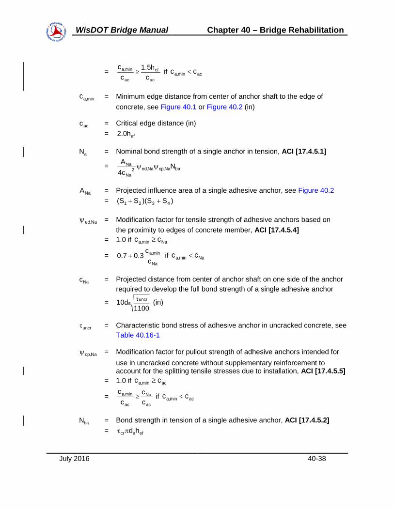
WisDOT Bridge Manual Chapter 40 – Bridge Rehabilitation
July 2016 40-38
= ac
ef
ac
min,a
ch5.1
cc
≥ if acmin,a cc <
min,ac = Minimum edge distance from center of anchor shaft to the edge of concrete, see Figure 40.1 or Figure 40.2 (in)
acc = Critical edge distance (in) = efh0.2
aN = Nominal bond strength of a single anchor in tension, ACI [17.4.5.1]
= baNa,cpNa,ed2Na
Na Nc4A
ψψ
NaA = Projected influence area of a single adhesive anchor, see Figure 40.2 = )SS)(SS( 4321 ++
Na,edψ = Modification factor for tensile strength of adhesive anchors based on the proximity to edges of concrete member, ACI [17.4.5.4] = 1.0 if Namin,a cc ≥
= Na
min,a
cc
3.07.0 + if Namin,a cc <
Nac = Projected distance from center of anchor shaft on one side of the anchor required to develop the full bond strength of a single adhesive anchor
= 1100
d10 uncra
τ (in)
uncrτ = Characteristic bond stress of adhesive anchor in uncracked concrete, see Table 40.16-1
Na,cpψ = Modification factor for pullout strength of adhesive anchors intended for use in uncracked concrete without supplementary reinforcement to account for the splitting tensile stresses due to installation, ACI [17.4.5.5] = 1.0 if acmin,a cc ≥
= ac
Na
ac
min,a
cc
cc
≥ if acmin,a cc <
baN = Bond strength in tension of a single adhesive anchor, ACI [17.4.5.2] = efacr hdπτ

WisDOT Bridge Manual Chapter 40 – Bridge Rehabilitation
July 2016 40-39
crτ = Characteristic bond stress of adhesive anchor in cracked concrete, see Table 40.16-1
Note: Where analysis indicates cracking at service load levels, adhesive anchors shall be qualified for use in cracked concrete in accordance with ICC-ES AC308 / ACI 355.4. For adhesive anchors located in a region of a concrete member where analysis indicates no cracking at service load levels, uncrτ shall be permitted to be used in place of crτ .
In addition to the checks listed above for all adhesive anchors, the factored sustained tensile force must be less than or equal to the factored sustained tensile resistance per ACI [17.3.1.2]:
s,uabatc NN55.0 ≥φ
40.16.4 Concrete Anchor Shear Capacity
Concrete anchors in shear fail in one of three ways: steel shear rupture, concrete breakout, or concrete pryout. Figure 40.3 shows the concrete breakout failure mechanism for anchors in shear.
The projected concrete breakout area, AVc, shown in Figure 40.3 is limited vertically by H, and in both horizontal directions by Si:
H = Minimum of:
1. The member depth (ha) or
2. 1.5 times the edge distance (ca1) (in).
Si = Minimum of:
1. Half the anchor spacing (S),
2. The perpendicular edge distance (ca2), or
3. 1.5 times the edge distance (ca1) (in).
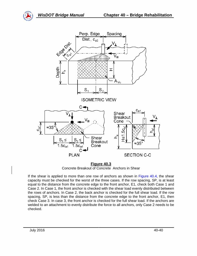
WisDOT Bridge Manual Chapter 40 – Bridge Rehabilitation
July 2016 40-40
Figure 40.3 Concrete Breakout of Concrete Anchors in Shear
If the shear is applied to more than one row of anchors as shown in Figure 40.4, the shear capacity must be checked for the worst of the three cases. If the row spacing, SP, is at least equal to the distance from the concrete edge to the front anchor, E1, check both Case 1 and Case 2. In Case 1, the front anchor is checked with the shear load evenly distributed between the rows of anchors. In Case 2, the back anchor is checked for the full shear load. If the row spacing, SP, is less than the distance from the concrete edge to the front anchor, E1, then check Case 3. In case 3, the front anchor is checked for the full shear load. If the anchors are welded to an attachment to evenly distribute the force to all anchors, only Case 2 needs to be checked.

WisDOT Bridge Manual Chapter 40 – Bridge Rehabilitation
July 2016 40-41
Figure 40.4 Concrete Anchor Shear Force Cases
The factored shear force on each anchor, Vu, must be less than or equal to the factored shear resistance, Vr. For mechanical and adhesive anchors:
cpvpcbvcsavsr VVVV φφφ ≤≤=
In which:
vsφ = Strength reduction factor for anchors in concrete, ACI [17.3.3] = 0.60 for brittle steel as defined in 40.16.1.1 = 0.65 for ductile steel as defined in 40.16.1.1
saV = Nominal steel strength of anchor in shear, ACI [17.5.1.2] = 0.6 utaV,se fA
V,seA = Effective cross-sectional area of anchor in shear (in2)
vcφ = Strength reduction factor for anchors in concrete, ACI [17.3.3] = 0.70 for anchors without supplementary reinforcement per 40.16.2 = 0.75 for anchors with supplementary reinforcement per 40.16.2
cbV = Nominal concrete breakout strength in shear, ACI [17.5.2.1]
= bV,pV,hV,cV,ed21a
Vc V)c(5.4
Aψψψψ

WisDOT Bridge Manual Chapter 40 – Bridge Rehabilitation
July 2016 40-42
VcA = Projected area of the concrete failure surface on the side of the concrete member at its edge for a single anchor, see Figure 40.3 = )SS(H 21 +
1ac = Distance from the center of anchor shaft to the edge of concrete in the direction of the applied shear, see Figure 40.3 and Figure 40.4 (in)
V,edψ = Modification factor for shear strength of anchors based on proximity to edges of concrete member, ACI [17.5.2.6] = 1.0 if 1a2a c5.1c ≥ (perpendicular shear)
= 1a
2a
c5.1c3.07.0 + if 1a2a c5.1c < (perpendicular shear)
= 1.0 (parallel shear)
2ac = Distance from the center of anchor shaft to the edge of concrete in the direction perpendicular to 1ac , see Figure 40.3 (in)
V,cψ = Modification factor for shear strength of anchors based on the presence or absence of cracks in concrete and the presence or absence of supplementary reinforcement, ACI [17.5.2.7] = 1.4 for anchors located in a region of a concrete member where analysis indicates no cracking at service load levels = 1.0 for anchors located in a region of a concrete member where analysis indicates cracking at service load levels without supplementary reinforcement per 40.16.2 or with edge reinforcement smaller than a No. 4 bar = 1.2 for anchors located in a region of a concrete member where analysis indicates cracking at service load levels with reinforcement of a No. 4 bar or greater between the anchor and the edge = 1.4 for anchors located in a region of a concrete member where analysis indicates cracking at service load levels with reinforcement of a No. 4 bar or greater between the anchor and the edge, and with the reinforcement enclosed within stirrups spaced at no more than 4 inches
V,hψ = Modification factor for shear strength of anchors located in concrete members with 1caa 5.1h < , ACI [17.5.2.8]
= 0.1hc5.1
a
1a ≥
ah = Concrete member thickness in which anchor is located measured parallel to anchor axis, see Figure 40.3 (in)

WisDOT Bridge Manual Chapter 40 – Bridge Rehabilitation
July 2016 40-43
V,pψ = Modification factor for shear strength of anchors based on loading direction, ACI [17.5] = 1.0 for shear perpendicular to the concrete edge, see Figure 40.3 = 2.0 for shear parallel to the concrete edge, see Figure 40.3
bV = Concrete breakout strength of a single anchor in shear in cracked concrete, per ACI [17.5.2.2] , shall be the smaller of:
5.11aca
2.0
a
e )c('f]d)dl(7[ (lb)
Where: aefe d8hl ≤= ad = Outside diameter of anchor (in) c'f = Specified compressive strength of concrete (psi)
and
5.11ac )c('f9
vpφ = Strength reduction factor for anchors in concrete = 0.65 for anchors without supplementary reinforcement per 40.16.2 = 0.75 for anchors with supplementary reinforcement per 40.16.2
cpV = Nominal concrete pryout strength of a single anchor, ACI [17.5.3.1] = cpN0.2
Note: The equation above is based on 5.2hef ≥ in. All concrete anchors must meet this requirement.
cpN = Nominal concrete pryout strength of an anchor taken as the lesser of:
mechanical anchors: ( ) bN,cpN,cN,ed2
ef
Nc Nh9A
ΨΨΨ
adhesive anchors: ( ) baNa,cpNa,ed2
Na
Na Nc4A
ΨΨ
and
( ) bN,cpN,cN,ed2
ef
Nc Nh9A
ΨΨΨ

WisDOT Bridge Manual Chapter 40 – Bridge Rehabilitation
July 2016 40-44
For shear in two directions, check both the parallel and the perpendicular shear capacity. For shear on an anchor near a corner, check the shear capacity for both edges and use the minimum.
40.16.5 Interaction of Tension and Shear
For anchors that are subjected to tension and shear, interaction equations must be checked per ACI [17.6].
If 2.0V
V
n
ua ≤φ
for the governing strength in shear, then the full strength in tension is permitted:
uan NN ≥φ . If 2.0N
N
n
ua ≤φ
for the governing strength in tension, then the full strength in shear is
permitted: uan VV ≥φ . If 2.0V
V
n
ua >φ
for the governing strength in shear and 2.0N
N
n
ua >φ
for the
governing strength in tension, then:
2.1V
VN
N
n
ua
n
ua ≤φ
+φ
40.16.6 Plan Preparation
The required minimum pullout capacity (as stated on the plans) is equal to the Nominal Tensile Resistance as determined in 40.16.3.
Typical notes for bridge plans (shown in all capital letters):
Adhesive anchors located in uncracked concrete:
ADHESIVE ANCHORS X/X-INCH (or No. X BAR). EMBED XX” IN CONCRETE. (Illustrative only, values must be calculated depending on the specific situation).
Adhesive anchors located in cracked concrete:
ADHESIVE ANCHORS X/X-INCH (or No. X BAR). EMBED XX” IN CONCRETE. ANCHORS SHALL BE APPROVED FOR USE IN CRACKED CONCRETE. (Illustrative only, values must be calculated depending on the specific situation).
When using anchors to anchor bolts or studs, the bolt, nut, and washer or the stud as detailed on the plans is included in the bid item “Adhesive Anchors _-Inch”.
For anchors using rebar, the rebar should be listed in the “Bill of Bars” and paid for under the bid item “Bar Steel Reinforcement HS Coated Structures”.

WisDOT Bridge Manual Chapter 40 – Bridge Rehabilitation
July 2016 40-49
40.19 Reinforcing Steel for Deck Slabs on Girders for Deck Replacements
Effective Span Ft-In
T=Slab Thickness
Inches Transverse Bars
& Spacing Longitudinal Bars
& Spacing
Longitudinal* Continuity Bars &
Spacing 4-0 6.5 #5 @ 8" #4 @ 8.5" #5 @ 7.5" 4-3 6.5 #5 @ 7.5" #4 @ 7.5" #5 @ 7.5" 4-6 6.5 #5 @ 7.5" #4 @ 7.5" #5 @ 7.5" 4-9 6.5 #5 @ 7" #4 @ 7.5" #5 @ 7.5" 5-0 6.5 #5 @ 6.5" #4 @ 7" #5 @ 7" 5-3 6.5 #5 @ 6.5" #4 @ 7" #5 @ 7" 5-6 6.5 #5 @ 6" #4 @ 6.5" #5 @ 6.5" 5-9 6.5 #5 @ 6" #4 @ 6.5" #5 @ 6.5" 2-3 7 #4 @ 9" #4 @ 11" #5 @ 6.5" 2-6 7 #4 @ 8.5" #4 @ 11" #5 @ 6.5" 2-9 7 #4 @ 8" #4 @ 11" #5 @ 6.5" 3-0 7 #4 @ 7.5" #4 @ 11" #5 @ 6.5" 3-3 7 #4 @ 7" #4 @ 11" #5 @ 6.5" 3-6 7 #4 @ 6.5" #4 @ 11" #5 @ 6.5" 3-9 7 #4 @ 6.5" #4 @ 10.5" #5 @ 6.5" 4-0 7 #4 @ 6" #4 @ 10" #5 @ 6.5" 4-3 7 #5 @ 9" #4 @ 9.5" #5 @ 7" 4-6 7 #5 @ 8.5" #4 @ 9" #5 @ 7" 4-9 7 #5 @ 8" #4 @ 8.5" #5 @ 7" 5-0 7 #5 @ 8" #4 @ 8.5" #5 @ 7" 4-3 7 #5 @ 7.5" #4 @ 8" #5 @ 7" 5-6 7 #5 @ 7' #4 @ 7" #5 @ 7" 5-9 7 #5 @ 7" #4 @ 7" #5 @ 7" 6-0 7 #5 @ 6.5" #4 @ 7" #5 @ 7" 6-3 7 #5 @ 6.5" #4 @ 7" #5 @ 7" 6-6 7 #5 @ 6" #4 @ 6.5" #5 @ 6.5" 6-9 7 #5 @ 6" #4 @ 6.5" #5 @ 6.5" 7-0 7 #5 @ 6" #4 @ 6" #5 @ 6" 4-0 7.5 #4 @ 7" #4 @ 10.5" #5 @ 6" 4-3 7.5 #4 @ 6.5" #4 @ 10.5" #5 @ 6" 4-6 7.5 #4 @ 6.5" #4 @ 10" #5 @ 6" 4-9 7.5 #4 @ 6" #4 @ 10" #5 @ 6"

WisDOT Bridge Manual Chapter 40 – Bridge Rehabilitation
July 2016 40-50
5-0 7.5 #5 @ 9" #4 @ 9.5" #5 @ 6" 5-3 7.5 #5 @ 8.5" #4 @ 9" #5 @ 6.5" 5-6 7.5 #5 @ 8" #4 @ 8.5" #5 @ 6.5" 5-9 7.5 #5 @ 8" #4 @ 8.5" #5 @ 6.5" 6-0 7.5 #5 @ 7.5" #4 @ 8" #5 @ 6.5" 6-3 7.5 #5 @ 7.5" #4 @ 7.5" #5 @ 6.5" 6-6 7.5 #5 @ 7" #4 @ 7.5" #5 @ 6.5" 6-9 7.5 #5 @ 7" #4 @ 6.5" #5 @ 6.5" 7-0 7.5 #5 @ 7" #4 @ 6.5" #5 @ 6.5" 7-3 7.5 #5 @ 6.5" #4 @ 6.5" #5 @ 6.5" 7-6 7.5 #5 @ 6.5" #5 @ 10" #5 @ 6.5" 7-9 7.5 #5 @ 6" #5 @ 10" #5 @ 6.5" 8-0 7.5 #5 @ 6" #5 @ 10" #5 @ 6.5" 8-3 7.5 #5 @ 6" #5 @ 9.5" #5 @ 6.5"
Table 40.19-1 Reinforcing Steel for Deck Slabs on Girders for Deck Replacements – HS20 Loading
Max. Allowable Design Stresses: fc' = 4000 psi, fy = 60 ksi, Top Steel 2-1/2" Clear, Bottom Steel 1-1/2" Clear, Future Wearing Surface = 20 lbs/ft. Transverse and longitudinal bars shown in table are for one layer only. Place identical steel in both top and bottom layer, except in negative moment region. Use in top layer for slab on steel girders in negative moment region when not designed for negative moment composite action.

WisDOT Bridge Manual Chapter 40 – Bridge Rehabilitation
July 2016 40-51
40.20 Fiber Reinforced Polymer (FRP)
40.20.1 Introduction
Fiber reinforced polymer (FRP) material is a composite composed of fibers encased in a polymer matrix. The fibers provide tensile strength while the resin protects the fibers and transfers load between them. FRP can be used to repair or to retrofit bridges. Repair is often defined as returning a member to its original condition after damage or deterioration while retrofitting refers to increasing the capacity of a member beyond its original capacity.
For plan preparations, FRP repairs and retrofits are categorized as either structural strengthening or non-structural protection. Contact the Bureau of Structures Design Section for current Special Provisions and for other FRP considerations.
40.20.2 Design Guidelines
While there is no code document for the design of FRP repairs and retrofits, there are two nationally recognized design guidelines: the Guide Specification for Design of Bonded FRP Systems for Repair and Strengthening of Concrete Bridge Elements (14.) hereinafter referred to as the AASHTO FRP Guide, and the Guide for the Design and Construction of Externally Bonded FRP Systems for Strengthening Concrete Structures ACI 440.2R-08 (15.) hereinafter referred to as the ACI FRP Guide.
Note: BOS has been evaluating the design methodologies found in the AASHTO FRP Guide and ACI RFP Guide. Noticeable differences between the guides warrants further investigation, with input from industry representation. FRP repairs and retrofits shall be in accordance with the applicable Special Provisions.
40.20.3 Applicability
Not all concrete structures can be retrofitted or repaired using FRP. Most FRP research has been conducted on normal sized members, therefore many of the design equations cannot be used with exceptionally large or deep members. Additionally, members with disturbed regions (D-regions) such as deep beams and corbels are outside of the scope of many design equations.
The structure must have some amount of load carrying capacity prior to the installation of the FRP. Due to the potential for premature debonding, FRP cannot be counted on to carry service loads; it may only be used increase the ultimate capacity of the structure for strength and extreme event load cases. The unrepaired or unretrofitted structure be able to carry the service dead and live loads:
𝑅𝑅𝑟𝑟 ≥ 𝜂𝜂𝑖𝑖[(𝐷𝐷𝐷𝐷 + 𝐷𝐷𝐷𝐷) + (𝐿𝐿𝐿𝐿 + 𝐼𝐼𝐼𝐼)]
Where:
Rr = factored resistance computed in accordance with AASHTO LRFD Section 5
WisDOT Bridge Manual Chapter 40 – Bridge Rehabilitation
July 2016 40-52
ηi = load modifier = 1.0
DC = force effects due to components and attachments
DW = force effects due to wear surfaces and utilities
LL = force effects due to live load
IM = force effects due to dynamic load allowance
If capacity is added in flexure to accommodate increased loads, the shear capacity of the member must be checked to ensure that it is still sufficient for the new loading. For non-structural FRP applications, applicability checks may not be required.
40.20.4 Materials
A typical FRP system consists of a primer, fibers, resin, bonding material (either additional resin or an adhesive), and a protective coating. FRP is specified in terms of the types of fiber and resin, the number of layers, the fiber orientation and the geometry. FRP is sold as a system and all materials used should be from the same system.
40.20.4.1 Fibers
The most common types of fiber used for bridge repairs are glass and carbon. Glass fibers are not as stiff or as strong as carbon, but they are much less expensive. Unless there is reason to do otherwise, it is recommended that glass fibers be used for corrosion protection and spall control. Carbon fibers should be used for strengthening and crack control.
Carbon fibers cannot be used where the FRP comes into contact with steel out of concerns for galvanic corrosion due to the highly conductive nature of carbon fibers. For applications where galvanic corrosion is a concern, glass fibers may be used, even in structural applications.
Often, FRP is requested by the region to provide column confinement. The engineer must determine if the requested confinement is true confinement where the FRP puts the column into triaxial compression to increase the capacity and ductility, or if the FRP is confining a patch from spalling off. In the case of true confinement (which is very rare in Wisconsin), carbon fibers should be used and the repair requires structural design. For spall control, glass fibers are acceptable and the repair is considered non-structural.
40.20.4.2 Coatings
After the FRP has been installed and fully cured, a protective coating is applied to the entire system. A protective coating is needed to protect against ultraviolet degradation and can also provide resistance to abrasion, wear, and chemicals. In situations where the FRP is submerged in water, inert protective coatings can help prevent compounds in the FRP from leaching into the water, mitigating environmental impacts.

WisDOT Bridge Manual Chapter 40 – Bridge Rehabilitation
July 2016 40-53
Protective coatings can be made from different materials depending on the desired coating characteristics. Common coating types include vinyl ester, urethane, epoxy, cementitious, and acrylic. Acrylic coatings are generally the least expensive and easiest to apply, though they may also be less durable. If no coating type is specified, it is likely that the manufacturer will provide an acrylic coating.
For shorter term repairs, acrylic coatings are sufficient, but longer repairs should consider other coating types such as epoxy. Any coating used must be compatible with the FRP system selected by the contractor.
40.20.4.3 Anchors
The bond between the FRP and the concrete is the most critical component of an FRP installation and debonding is the most common FRP failure mode. Certain FRP configurations use anchors to increase the attachment of the FRP and attempt to delay or prevent debonding. These anchors can consist of near surface mounted bars, fiber anchors, additional FRP strips, or mechanical anchors such as bolts. It is permitted to use additional U-wrap strips to anchor flexural FRP, but the use of additional longitudinal strips to anchor shear FRP is prohibited. The use of additional U-wrap strips for flexural anchorage is required in some instances.
Because neither design guide requires anchorage or provides information as to what constitutes anchorage, it is left to the discretion of the designer to determine if anchorage should be used and in what quantities. The use of anchors is highly encouraged, particularly for shear applications and in situations where there is increased potential for debonding such as reentrant corners.
Specifying anchors will add cost to the repair, but these costs may be offset by increased capacity accorded to anchored systems in shear. The additional costs can also be justified if debonding is a concern. If the designer chooses to use anchors, anchors should be shown on plans, but the design of the anchors is left to the manufacturer.
40.20.5 Flexure
Flexural FRP is applied along the tension face of the member, where it acts as additional tension reinforcement. The fibers should be oriented along the length of the member.
40.20.5.1 Pre-Design Checks
If the design of the FRP will be provided by the contractor or their consultant, the engineer must still perform certain checks before specifying FRP in the plans. For flexure, the engineer must check that the structure has sufficient capacity to carry service loads without additional capacity from the FRP, as discussed in 40.20.3.
40.20.5.2 Composite Action
Composite action of the deck slab can be considered when designing flexural FRP repairs for girders, provided that the deck was designed to be composite. If composite action is

WisDOT Bridge Manual Chapter 40 – Bridge Rehabilitation
July 2016 40-54
considered, composite section properties must be computed. These properties should be substituted into the design equations presented in this section. Accounting for composite action will increase the capacity provided by the FRP.
40.20.5.3 Pre-Existing Substrate Strain
Unless all loads are removed from the member receiving FRP (including self-weight), there will be strain present in the concrete when the FRP is applied. This initial or pre-existing substrate strain εbi is computed through elastic analysis. All loads supported by the member during FRP installation should be considered and cracked section properties should be considered if necessary.
40.20.5.4 Deflection and Crack Control
Conduct standard LRFD serviceability checks for deflection and crack control while accounting for the contribution of the FRP. Because both the FRP and the concrete will be in the elastic zone at service levels, standard elastic analysis can be used to determine stresses and strains. Transformed section analysis can be used to transform the FRP into an equivalent area of concrete for the purposes of analysis. The condition of the member determines if the cracked or uncracked section properties should be used in computations.
40.20.6 Shear
In shear repair/retrofitting applications, the FRP acts essentially as external stirrups. The FRP wrap is applied with the fibers running transverse to the member.
40.20.6.1 Pre-Design Checks
If the design of the FRP will be provided by the contractor or their consultant, the engineer must still perform certain checks before specifying FRP in the plans. For shear, the engineer must check that the structure has sufficient capacity to carry service loads without additional capacity from the FRP, as discussed in 40.20.3.
Additionally, the engineer must ensure that the amount of FRP capacity required does not exceed the maximum allowable shear reinforcement. It is important to note that the FRP capacity listed on the plans will be a factored capacity, while the maximum allowable shear reinforcement check is for an unfactored capacity. Strength reduction factors must be incorporated to make a proper comparison.
If the FRP capacity is close to the maximum allowed, the designer must take care to ensure that a design is feasible. The capacity provided by FRP depends on the number of FRP layers, with each additional layer providing a discrete increase in capacity. There may be a situation where n layers does not provide enough capacity, but n+1 layers provides too much capacity and violates the maximum allowable shear reinforcement criteria. Changes in spacing of the wraps may help decrease the capacity provided by the FRP.

WisDOT Bridge Manual Chapter 40 – Bridge Rehabilitation
July 2016 40-55
Example problems in shear can be found in the appendices of NCHRP Report 655 (16) and potential shear wrapping configurations can be found in NCHRP Report 678 (17).

WisDOT Bridge Manual Chapter 40 – Bridge Rehabilitation
July 2016 40-56
40.21 References
1. A Study of Policies for the Protection, Repair, Rehabilitation, and Replacement of Concrete Bridge Decks by P.D. Cady, Penn. DOT.
2. Concrete Sealers for Protection of Bridge Structures, NCHRP Report 244, December, 1981.
3. Durable Bridge Decks by D. G. Manning and J. Ryell, Ontario Ministry Transportation and Communications, April, 1976.
4. Durability of Concrete Bridge Decks, NCHRP Report 57, May, 1979.
5. Rehabilitation and Replacement of Bridges on Secondary Highways and Local Roads, NCHRP Report 243, December, 1981.
6. Strength of Concrete Bridge Decks by D. B. Beal, Research Report 89 NY DOT, July, 1981.
7. Latex Modified Concrete Bridge Deck Overlays - Field Performance Analysis by A. G. Bisharu, Report No. FHWA/OH/79/004, October, 1979.
8. Standard Practice for Concrete Highway Bridge Deck Construction by ACI Committee 345, Concrete International, September, 1981.
9. The Effect of Moving Traffic on Fresh Concrete During Bridge Deck Widening by H. L. Furr and F. H. Fouad, Paper Presented 61 Annual TRB Meeting, January, 1982.
10. Control of Cracking in Concrete Structures by ACI Committee 224, Concrete International, October, 1980.
11. Discussion of Control of Cracking in Concrete Structures by D. G. Manning, Concrete International, May, 1981.
12. Effects of Traffic-Induced Vibrations on Bridge Deck Repairs, NCHRP Report 76, December, 1981.
13. Building Code Requirements for Structural Concrete (ACI 318-11) and Commentary, 2011.
14. AASHTO. 2012. Guide Specifications for the Design of Bonded FRP Systems for Repair and Strenghening of Concrete Bridge Elements. Washington D.C.: American Assocation of State Highway and Transportation Officials, 2012
15. ACI. 2008. Guide for the Design and Construction of Externally Bonded FRP Systems for Strengthening Concrete Structures. Farmington Hills MI: American Concrete Institute, 2008. ACI 440.2R-08.

Table of ContentsE45-1 Reinforced Concrete Slab Rating Example LRFR.............................................................................
E45-1.1 Design Criteria ......................................................................................................E45-1.2 Analysis of an Interior Strip one foot width ...........................................................
E45-1.2.1 Dead Loads (DC, DW) ........................................................................E45-1.2.2 Live Load Distribution (Interior Strip) ..................................................E45-1.2.3 Nominal Flexural Resistance: (Mn) .....................................................E45-1.2.4 General Load Rating Equation (for flexure) ........................................E45-1.2.5 Design Load (HL-93) Rating ...............................................................E45-1.2.6 Permit Vehicle Load Ratings ................................................................
E45-1.2.6.1 Wis-SPV Permit Rating with Single Lane Distribution w/FWS .........................................................................................................E45-1.2.6.2 Wis-SPV Permit Rating with Single Lane Distribution w/oFWS .........................................................................................................E45-1.2.6.3 Wis-SPV Permit Rating with Multi Lane Distribution w/oFWS .........................................................................................................
E45-1.3 Summary of Rating ...............................................................................................
234445679
9
11
1314
WisDOT Bridge Manual Chapter 45 – Bridge Rating

E45-1 Reinforced Concrete Slab Rating Example - LRFR
The 3-span continuous haunched slab structure shown in the Design Example from Chapter 18is rated below. This same basic procedure is applicable for flat slab structures. The Bureau ofStructures rates concrete slab structures for the Design Load (HL-93) and for Permit VehicleLoads on an Interior Strip. The Permit Vehicle may be the Wisconsin Standard Permit Vehicle(Wis-SPV) or an actual Single-Trip Permit Vehicle. This bridge was analyzed using a slab width equal to one foot.
Figure E45-1.1
Figure E45-1.2
July 2016 45E1-2
WisDOT Bridge Manual Chapter 45 – Bridge Rating

E45-1.1 Design CriteriaGeometry:
L1 38.0 ft Span 1 Length
L2 51.0 ft Span 2 Length
L3 38.0 ft Span 3 Length
slabwidth 42.5 ft out to out width of slab
skew 6 deg skew angle (RHF)
wroadway 40.0 ft clear roadway width
covertop 2.5 in concrete cover on top bars (includes 1/2in wearing surface)
coverbot 1.5 in concrete cover on bottom bars
dslab 17 in slab depth (not including 1/2in wearing surface)
Dhaunch 28 in haunch depth (not including 1/2in wearing surface)
Ast_0.4L 1.71 Area of longitudinal bottom steel at 0.4L (# 9's at 7in centers)in2
ft
Ast_pier 1.88 Area of longitudinal top steel at Pier (# 8's at 5in centers)in2
ft
Material Properties:
f'c 4 ksi concrete compressive strength
fy 60 ksi yield strength of reinforcement
Ec 3800 ksi modulus of elasticity of concrete
Es 29000 ksi modulus of elasticity of reinforcement
n 8 Es / Ec (modular ratio)
Weights:
wc 150 pcf concrete unit weight
wLF 387 plf weight of Type LF parapet (each)
July 2016 45E1-3
WisDOT Bridge Manual Chapter 45 – Bridge Rating

E45-1.2 Analysis of an Interior Strip - one foot width
Use Strength Limit States to rate the concrete slab bridge. LRFD [6.4.2.2]The influence of ADTT and skew on force effects are ignored for slab bridges (See 18.3.2.2).
E45-1.2.1 Dead Loads (DC, DW)
The slab dead load, DCslab, and the section properties of the slab, do not include the 1/2 inchwearing surface. But the 1/2 inch wearing surface load, DCWS, of 6 psf must be including in theanalysis of the slab. For a one foot slab width:
DCws 6 1/2 inch wearing surface load, plf
The parapet dead load is uniformly distributed over the full width of the slab when analyzing anInterior Strip. For a one foot slab width:
DCpara 2wLF
slabwidth DCpara 18 plf
The unfactored dead load moments, MDC, due to slab dead load (DCslab), parapet dead load(DCpara), and the 1/2 inch wearing surface (DCws) are shown in Chapter 18 Example (Table E18.4).
The structure was designed for a possible future wearing surface, DWFWS, of 20 psf.
DWFWS 20 Possible wearing surface, plf
E45-1.2.2 Live Load Distribution (Interior Strip)
Live loads are distributed over an equivalent width, E, as calculated below.The live loads to be placed on these widths are axle loads (i.e., two lines of wheels) and the full lane load. The equivalent distribution width applies for both live load moment and shear.
Single - Lane Loading: E 10.0 5.0 L1 W1 0.5= in
Multi - Lane Loading: E 84.0 1.44 L1 W1 0.5= < 12.0WNL in
Where:
L1 = modified span length taken equal to the lesser of the actual span or 60ft (L1 in ft)
W1 = modified edge to edge width of bridge taken to be equal to the lesser of the actual width or 60ft for multi-lane loading, or 30ft for single-lane loading (W1 in ft)
W = physical edge to edge width of bridge (W in ft)
July 2016 45E1-4
WisDOT Bridge Manual Chapter 45 – Bridge Rating

NL = number of design lanes as specified in LRFD [3.6.1.1.1]
For single-lane loading:
(Span 1, 3) E 10.0 5.0 38 30( )0.5 E 178.819 in
(Span 2) E 10.0 5.0 51 30( )0.5 E 205.576 in
For multi-lane loading:
12.0WNL 12.0
42.53
= 170= in
(Span 1, 3) E 84.0 1.44 38 42.5( )0.5 E 141.869 in <170" O.K.
(Span 2) E 84.0 1.44 51 42.5( )0.5 E 151.041 in <170" O.K.
E45-1.2.3 Nominal Flexural Resistance: (Mn)
The depth of the compressive stress block, (a) is (See 18.3.3.2.1):
a = As fs
α1 f'c b
where:
As = area of developed reinforcement at section (in2)fs = stress in reinforcement (ksi)f'c 4 ksi
b 12 in
α1 0.85 (for f'C < 10.0 ksi) LRFD [5.7.2.2]As shown throughout the Chapter 18 Example, when fs is assumed to be equal to fy, and isused to calculate (a), the value of c/ds will be < 0.6 (for fy = 60 ksi) per LRFD [5.7.2.1]Therefore the assumption that the reinforcement will yield (fs = fy) is correct. The value for (c)and (ds) are calculated as:
c = a
β1
β1 0.85
ds = slab depth(excl. 1/2" wearing surface) - bar clearance - 1/2 bar diameter
July 2016 45E1-5
WisDOT Bridge Manual Chapter 45 – Bridge Rating

For rectangular sections, the nominal moment resistance, Mn, (tension reinforcement only)equals:
Mn = As fy dsa2
Minimum Reinforcement Check
All sections throughout the bridge meet minimum reinforcement requirements, because thiswas checked in the chapter 18 Design example. Therefore, no adjustment to nominalresistance (Mn) or moment capacity is required. LRFD [6.5.7]
Maximum Reinforcement Check
The area of reinforcement to be used in calculating nominal resistance (Mn) or momentcapacity, shall not exceed the maximum amount permitted in LRFD [5.7.3.3.1], as stated inLRFR[6.5.6]. This check will be ignored because the article referenced in the LRFDSpecifications, as mentioned above, has been removed.
|
E45-1.2.4 General Load - Rating Equation (for flexure)
RF = C γDC MDC γDW MDW
γL MLL_IM LRFR [6.4.2.1]
For the Strength Limit State:
C = ϕc ϕs ϕ( ) Rn
where:
Rn = Mn (for flexure)
ϕc ϕs 0.85
Factors affecting Capacity (C):
Resistance Factor (), for Strength Limit State LRFR [6.5.3]
ϕ 0.9 for flexure (all reinforced concrete section in the Chapter 18Example were found to be tension-controlled sections as definedin LRFD [5.7.2.1]).
Condition Factor (c) per Chapter 45.3.2.4
ϕc 1.0
System Factor (s) Per Chapter 45.3.2.5
ϕs 1.0 for a slab bridge
July 2016 45E1-6
WisDOT Bridge Manual Chapter 45 – Bridge Rating

E45-1.2.5 Design Load (HL-93) Rating
Use Strength I Limit State to find the Inventory and Operating Ratings LRFR [6.4.2.2, 6.5.4.1] Equivalent Strip Width (E) and Distribution Factor (DF):
Use the smaller equivalent width (single or multi-lane), when (HL-93) live load is to bedistributed, for Strength I Limit State. Multi-lane loading values will control for this bridge.
The distribution factor, DF, is computed for a s lab width equal to one foot.
DF = 1E
(where E is in feet)
The multiple presence factor, m, has been included in the equations for distribution width, E,and therefore is not used to adjust the distribution factor, DF, LRFD [3.6.1.1.2].
Spans 1 & 3:
DF = 1/(141"/12) = 0.0851 lanes / ft-slab
Span 2:
DF = 1/(151"/12) = 0.0795 lanes / ft-slab
Look at the distribution factor calculated for each span and select the largest value. Thissingle value is to be applied along the entire length of the bridge.Therefore use: lanes / ft-slab for all spans.DF 0.0851
Dynamic Load Allowance (IM)
IM 33 % LRFR [6.4.3.3]
Live Loads (LL)
The live load combinations used for Strength I Limit State are shown in the Chapter 18Example in Table E18.2 and E18.3. The unfactored moments due to Design Lane, DesignTandem, Design Truck and 90%{Double Design Truck + Design Lanes] are shown in Chapter18 Example (Table E18.4).
Rating for Flexure
RF = ϕc ϕs ϕ( ) Mn γDC MDC γDW MDW
γL MLL_IM
Load Factors
γDC 1.25 Chapter 45 Table 45.3-1
γDW 1.50 WisDOT policy is to always use 1.50; Chapter 45 Table 45.3-1
γLi 1.75 (Inventory Rating) Chapter 45 Table 45.3-1
γLo 1.35 (Operating Rating) Chapter 45 Table 45.3-1
July 2016 45E1-7
WisDOT Bridge Manual Chapter 45 – Bridge Rating

The Design Load Rating was checked at 0.1 pts. along the structure and at the slab/haunchintercepts. The governing location, for this example, is in span 1 at the 0.4 pt.
Span 1 (0.4 pt.)
Inventory:
RFi = ϕc ϕs ϕ( ) Mn γDC MDC γDW MDW
γLi MLL_IM
Ast_0.4L 1.71in2
ftand α1 0.85 (for f'C < 10.0 ksi) LRFD [5.7.2.2]
ds 17.0 1.5 0.6 ds 14.9 in
aAst_0.4L fy
α1 f'c b a 2.51 in
Mn Ast_0.4L fy dsa2
Mn 1399.7 kip in
Mn 116.6 kip ft
MDC 18.1 kip ft (from Chapter 18 Example, Table E18.4)
MDW 0.0 kip ft (additional wearing surface not for HL-93 rating runs )
The positive live load moment shall be the largest caused by the following (from Chapter 18Example, Table E18.4):
Design Tandem (+IM) + Design Lane: (37.5 kip-ft + 7.9 kip-ft) = 45.4 kip-ftDesign Truck (+IM) + Design Lane: (35.4 kip-ft + 7.9 kip-ft) = 43.3 kip-ft
Therefore:
MLL_IM 45.4 kip ft
Inventory:
RFiϕc ϕs ϕ( ) Mn γDC MDC γDW MDW
γLi MLL_IM
RFi 1.04
Operating:
RFoϕc ϕs ϕ( ) Mn γDC MDC γDW MDW
γLo MLL_IM
RFo 1.34
July 2016 45E1-8
WisDOT Bridge Manual Chapter 45 – Bridge Rating

Rating for Shear:
Slab bridge designed for dead load and (HL-93) live load moments in conformance with LRFD[4.6.2.3] may be considered satisfactory in shear LRFD [5.14.4.1]. This bridge was designedusing this procedure, therefore a shear rating is not required.
The Rating Factors, RF, for Inventory and Operating Rating are shown on the plans and alsoon the load rating summary sheet.
E45-1.2.6 Permit Vehicle Load Ratings For any bridge design (new or rehabilitation) or bridge re-rate, the Wisconsin Standard PermitVehicle (Wis-SPV) shall be analyzed (per 45.6).
The bridge shall be analyzed for this vehicle considering both single-lane and multi-lanedistribution. Also, the vehicle will be analyzed assuming it is mixing with other traffic on thebridge and that full dynamic load allowance is utilized. Future wearing surface will not beconsidered.
Since this example is rating a newly designed bridge, and additional check is required. Thedesigner shall ensure that the results of a single-lane analysis utilizing the future wearingsurface are greater than 190 kips MVW.
Use Strength II Limit State to find the Permit Vehicle Load Rating LRFR [6.4.2.2, 6.5.4.2.1].
E45-1.2.6.1 Wis-SPV Permit Rating with Single Lane Distribution w/ FWS Equivalent Strip Width (E) and Distribution Factor (DF)
The equivalent width from single-lane loading is used, when Permit Vehicle live load is to bedistributed, for Strength II Limit State LRFR [6.4.5.4.2.2].Calculate the distribution factor, DF, and divide it by (1.20) to remove the effects of the multiplepresence factor (m), which are present in the equation for equivalent width (E) LRFR [6.3.2,C6.4.5.4.2.2, Table 6-6].
The distribution factor, DF, is computed for a slab width equal to one foot.
DF = 1
E 1.20( ) (where E is in feet)
Spans 1 &3:
DF = 1/(178"/12)(1.20) = 0.0562 lanes / ft-slab
Span 2:
DF = 1/(205"/12)(1.20) = 0.0488 lanes / ft-slab
Look at the distribution factor calculated for each span and select the largest value.This single value is to be applied along the entire length of the bridge.
Therefore use: lanes / ft-slab for all spans. DF 0.0562
July 2016 45E1-9
WisDOT Bridge Manual Chapter 45 – Bridge Rating

Dynamic Load Allowance (IM)
IM 33 % LRFR [6.4.5.5]
Rating for Flexure
RF = ϕc ϕs ϕ( ) Mn γDC MDC γDW MDW
γL MLL_IM
Load Factors
γDC 1.25 Chapter 45 Table 45.3-1
γDW 1.50 WisDOT policy is to always use 1.50; Chapter 45 Table 45.3-1
γL 1.20 WisDOT Policy is to designate the (Wis_SPV) as a "Single-Trip"vehicle with no escorts. Current policy is to select the value for Lfrom Chapter 45 Table 45.3-3
The Maximum Permit Vehicle Load was checked at 0.1 pts. along the structure and at theslab/haunch intercepts. The governing location is the C/L of Pier.
At C/L of Pier
Permit Vehicle:
RF = ϕc ϕs ϕ( ) Mn γDC MDC γDW MDW
γL MLL_IM
Ast_pier 1.88in2
ftand α1 0.85 (for f'C < 10.0 ksi) LRFD [5.7.2.2]
ds 28.0 2.0 0.5 ds 25.5 in
aAst_pier fy
α1 f'c b a 2.76 in
Mn Ast_pier fy dsa2
Mn 2720.5 kip in
Mn 226.7 kip ft
MDC 59.2 kip ft (from Chapter 18 Example, Table E18.4)
July 2016 45E1-10
WisDOT Bridge Manual Chapter 45 – Bridge Rating

MDW 1.5 kip ft
The live load moment at the C/L of Pier due to the Wisconsin Standard Permit Vehicle(Wis-SPV) having a gross vehicle load of 190 kips and utilizing single lane distribution is:
MLL_IM 65.2 kip ft
Permit:
RFpermitϕc ϕs ϕ( ) Mn γDC MDC γDW MDW
γL MLL_IM
RFpermit 1.63
The maximum Wisconsin Standard Permit Vehicle (Wis_SPV) load is:
RFpermit 190( ) 310 kips which is > 190k, Check OK
This same procedure used for the (Wis-SPV) can also be used when evaluating the bridge foran actual "Single-Trip Permit" vehicle.
Rating for Shear:
WisDOT does not rate Permit Vehicles on slab bridges based on shear.
E45-1.2.6.2 Wis-SPV Permit Rating with Single Lane Distribution w/o FWS Equivalent Strip Width (E) and Distribution Factor (DF)
The equivalent width from single-lane loading is used, when Permit Vehicle live load is to bedistributed, for Strength II Limit State LRFR [6.4.5.4.2.2].Calculate the distribution factor, DF, and divide it by (1.20) to remove the effects of the multiplepresence factor (m), which are present in the equation for equivalent width (E) LRFR [6.3.2,C6.4.5.4.2.2, Table 6-6].
The distribution factor, DF, is computed for a slab width equal to one foot.
DF = 1
E 1.20( ) (where E is in feet)
Spans 1 &3:
DF = 1/(178"/12)(1.20) = 0.0562 lanes / ft-slab
Span 2:
DF = 1/(205"/12)(1.20) = 0.0488 lanes / ft-slab
July 2016 45E1-11
WisDOT Bridge Manual Chapter 45 – Bridge Rating

Look at the distribution factor calculated for each span and select the largest value.This single value is to be applied along the entire length of the bridge.
Therefore use: lanes / ft-slab for all spans. DF 0.0562
Dynamic Load Allowance (IM)
IM 33 % LRFR [6.4.5.5]
Rating for Flexure
RF = ϕc ϕs ϕ( ) Mn γDC MDC γDW MDW
γL MLL_IM
Load Factors
γDC 1.25 Chapter 45 Table 45.3-1
γL 1.20 WisDOT Policy is to designate the (Wis_SPV) as a "Single-Trip"vehicle with no escorts. Current policy is to select the value for Lfrom Chapter 45 Table 45.3-3
The Maximum Permit Vehicle Load was checked at 0.1 pts. along the structure and at theslab/haunch intercepts. The governing location is the C/L of Pier.
At C/L of Pier
Permit Vehicle:
RF = ϕc ϕs ϕ( ) Mn γDC MDC γDW MDW
γL MLL_IM
Ast_pier 1.88in2
ftand α1 0.85 (for f'C < 10.0 ksi) LRFD [5.7.2.2]
ds 28.0 2.0 0.5 ds 25.5 in
aAst_pier fy
α1 f'c b a 2.76 in
July 2016 45E1-12
WisDOT Bridge Manual Chapter 45 – Bridge Rating

Mn Ast_pier fy dsa2
Mn 2720.5 kip in
Mn 226.7 kip ft
MDC 59.2 kip ft (from Chapter 18 Example, Table E18.4)
The live load moment at the C/L of Pier due to the Wisconsin Standard Permit Vehicle(Wis-SPV) having a gross vehicle load of 190 kips and utilizing single lane distribution is:
MLL_IM 65.2 kip ft
Permit:
RFpermitϕc ϕs ϕ( ) Mn γDC MDC
γL MLL_IM
RFpermit 1.66
The maximum Wisconsin Standard Permit Vehicle (Wis_SPV) load is:
RFpermit 190( ) 316 kips
This same procedure used for the (Wis-SPV) can also be used when evaluating the bridge foran actual "Single-Trip Permit" vehicle.
E45-1.2.6.3 Wis-SPV Permit Rating with Multi Lane Distribution w/o FWS
Rating for Flexure
RF = ϕc ϕs ϕ( ) Mn γDC MDC
γL MLL_IM
The capacity of the bridge to carry the Permit Vehicle Load was checked at 0.1 pts. along thestructure and at the slab/haunch intercepts. The governing location is at the C/L of Pier.
Load Factors
γDC 1.25 Chapter 45 Table 45.3-1
γDW 1.50 WisDOT policy is to always use 1.50; Chapter 45 Table 45.3-1
γL 1.30 WisDOT Policy when analyzing the Wis-SPV as an "Annual Permit"vehicle with no escorts
July 2016 45E1-13
WisDOT Bridge Manual Chapter 45 – Bridge Rating

At C/L of Pier
Permit Vehicle:
RFpermit = ϕc ϕs ϕ( ) Mn γDC MDC
γL MLL_IM
Mn 226.7 kip ft (as shown previously)
MDC 59.2 kip ft (as shown previously)
The live load moment at the C/L of Pier due to the Wisconsin Permit Vehicle (Wis_SPV) havinga gross vehicle load of 190 kips and a DF of 0.0851 lanes/ft-slab:
MLL_IM 98.7 kip ft
RFpermitϕc ϕs ϕ( ) Mn γDC MDC
γL MLL_IM
RFpermit 1.01
The Wisconsin Standard Permit Vehicle (Wis_SPV) load that can be carried by the bridge is:
RFpermit 190( ) 193 kips
E45-1.3 Summary of Rating
Inventory OperatingSingle DF w/ FWS
Single DF w/o FWS
Multi DF w/o FWS
Strength I Flexure 1.04 1.34 N/A 310 316 190N/A N/A N/A Optional Optional OptionalService I
Limit StateDesign Load Rating
Legal Load Rating
Permit Load Rating (kips)Slab - Interior Strip
July 2016 45E1-14
WisDOT Bridge Manual Chapter 45 – Bridge Rating