rvcebasiceee.wikispaces.comrvcebasiceee.wikispaces.com/file/view/electric wiring... · web viewunit...
TRANSCRIPT

UNIT 5: ELECTRIC WIRING
Introduction
A network of wires drawn connecting the meter board to the various energy consuming loads (lamps, fans, motors etc) through control and protective devices for efficient distribution of power is known as electrical wiring.
Electrical wiring done in residential and commercial buildings to provide power for lights, fans, pumps and other domestic appliances is known as domestic wiring. There are several wiring systems in practice.
Two- way and Three- way Control of Lamps:
The domestic lighting circuits are quite simple and they are usually controlled from one point. But in certain cases it might be necessary to control a single lamp from more than one point (Two or Three different points).
For example: staircases, long corridors, large halls etc.
Two-way Control of lamp:
Two-way control is usually used for staircase lighting. The lamp can be controlled from two different points: one at the top and the other at the bottom - using two- way switches which strap wires interconnect. They are also used in bedrooms, big halls and large corridors. The circuit is shown in the following figure.

Switches S1 and S2 are two-way switches with a pair of terminals 1&2, and 3&4 respectively. When the switch S1 is in position1 and switch S2 is in position 4, the circuit does not form a closed loop and there is no path for the current to flow and hence the lamp will be OFF. When S1
is changed to position 2 the circuit gets completed and hence the lamp glows or is ON. Now if S2
is changed to position 3 with S1 at position 2 the circuit continuity is broken and the lamp is off. Thus the lamp can be controlled from two different points.
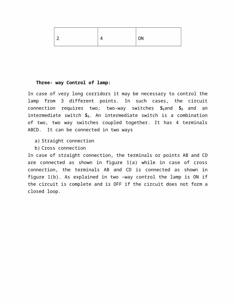
Position of S1 Position of S2 Condition of lamp
1 3 ON
1 4 OFF
2 3 OFF
2 4 ON
Three- way Control of lamp:
In case of very long corridors it may be necessary to control the lamp from 3 different points. In such cases, the circuit connection requires two; two-way switches S1and S2 and an intermediate switch S3. An intermediate switch is a combination of two, two way switches coupled together. It has 4 terminals ABCD. It can be connected in two ways
a) Straight connectionb) Cross connection
In case of straight connection, the terminals or points AB and CD are connected as shown in figure 1(a) while in case of cross connection, the terminals AB and CD is connected as shown in figure 1(b). As explained in two –way control the lamp is ON if the circuit is complete and is OFF if the circuit does not form a closed loop.
The condition of the lamp is given in the table depending on the positions of the switches S1, S2
and S3.
Position of S3 Position of S1 Position of S2 Condition of the lamp
1
Straight connection
1
1
2
2
3
4
3
4
ON
OFF
OFF
ON
2
Cross connection
1
1
2
2
3
4
3
4
OFF
ON
ON
OFF

Necessity and Types of Earthing
Introduction to Earthing:
Earthing is to connect any electrical equipment to earth with a very low resistance wire, making it to attain earth’s potential. The body of any electrical equipment is connected to the earth by means of a wire of negligible resistance to safely discharge electric energy, which may be due to failure of the insulation, line coming in contact with the casing etc. Earthing brings the potential of the body of the equipment to ZERO i.e. to the earth’s potential, thus protecting the operating personnel against electrical shock. The body of the electrical equipment is not connected to the supply neutral because due to long transmission lines and intermediate substations, the same neutral wire of the generator will not be available at the load end. Even if the same neutral wire is running it will have a self-resistance, which is higher than the human body resistance. Hence, the body of the electrical equipment is connected to earth only.
Necessity of Earthing:
1. To protect the operating personnel from danger of shock in case they come in contact with the charged frame due to defective insulation.
2. To maintain the line voltage constant under unbalanced load condition. 3. Protection of the equipments 4. Protection of large buildings and all machines fed from overhead lines against lightning.
Methods of Earthing:
The earth resistance for copper wire is 1 ohm and that of Galvanized Iron (G I) wire less than 3 ohms. The earth resistance should be kept as low as possible so that the neutral of any electrical system, which is earthed, is maintained almost at the earth potential. The typical value of the earth resistance at powerhouse is 0. 5 ohm and that at substation is 1 ohm.
1. Plate earthing
2. Pipe earthing
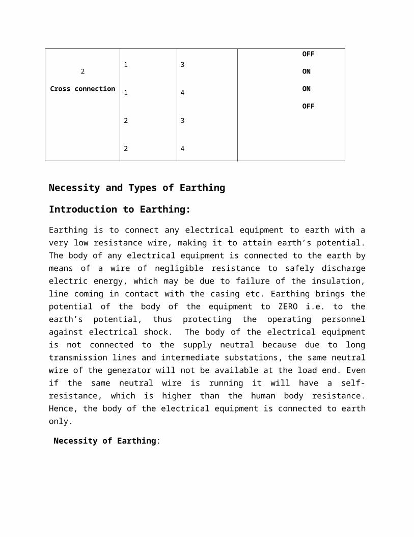
Plate Earthing
In this method a copper plate of 60cm x 60cm x 3.18cm or a GI plate of the size 60cm x 60cm x 6.35cm is used for earthing. The plate is placed vertically down inside the ground at a depth of 3m and is embedded in alternate layers of coal and salt for a thickness of 15 cm. In addition, water is poured for keeping the earth electrode resistance value well below a maximum of 5 ohms. The earth wire is securely bolted to the earth plate. A cement masonry chamber is built with a cast iron cover for easy regular maintenance.
Pipe Earthing
Earth electrode made of a GI (galvanized) iron pipe of 38mm in diameter and length of 2m (depending on the current) with 12mm holes on the surface is placed upright at a depth of 4.75m in a permanently wet ground. To keep the value of the earth resistance at the desired level, the area (15 cms) surrounding the GI pipe is filled with a mixture of salt and coal.. The efficiency of the earthing system is improved by pouring water through the funnel periodically. The GI earth wires of sufficient cross- sectional area are run through a 12.7mm diameter pipe (at 60cms below) from the 19mm diameter pipe and secured tightly at the top as shown in the following figure.
Note: When compared to the plate earth system the pipe earth system can carry larger leakage currents as a much larger surface area is in contact with the soil for a given electrode size. The system also enables easy maintenance as the earth wire connection is housed at the ground level.

Elementary ideas of Fuses and MCB
FUSE
The electrical equipments are designed to carry a particular rated value of current under normal circumstances. Under abnormal conditions such as short circuit, overload or any fault the current raises above this value, damaging the equipment and sometimes resulting in fire hazard. Fuses are pressed into operation under such situations.
Fuse is a safety device used in any electrical installation, which forms the weakest link between the supply and the load. It is a short length of wire made of lead / tin /alloy of lead and tin/ zinc having a low melting point and low ohmic losses. Under normal operating conditions it is designed to carry the full load current. If the current increases beyond this designed value due any of the reasons mentioned above, the fuse melts (said to be blown) isolating the power supply from the load as shown in the following figures.
Figure a. Under normal conditions
Figure b. Under abnormal conditions

Terms Related with Fuses
1. Rated current: It is the maximum current, which a fuse can carry without undue heating or melting.
It depends on the following factors:
a. Permissible temperature rise of the contacts of the fuse holder and the b. fuse materialc. Degree of deterioration due to oxidation
2. Fusing current: The minimum current at which the fuse melts is known as the fusing current. It depends on the material characteristics, length, diameter, cross-sectional area of the fuse element and the type of enclosure used.
3. Fusing Factor: It is the ratio of the minimum fusing current to the rated current. It is always greater than unity.
Characteristics of Fuse Material
The material used for fuse wires must have the following characteristics
1. Low melting point2. Low ohmic losses3. High conductivity4. Lower rate of deterioration
Advantages of Fuses:
1. Fast acting2. Highly reliable3. Relatively cheaper in comparison to other high current interrupting device
Disadvantages of Fuses:
2. Requires replacement3. The associated high temperature rise will affect the performance of other devices.

Miniature Circuit Breaker (MCB)
Nowadays we use more commonly miniature circuit breaker or MCB in low voltage electrical network instead of fuse.
Working Principle Miniature Circuit Breaker
There are two arrangement of operation of miniature circuit breaker. One due to thermal effect of over current and other due to electromagnetic effect of over current. The thermal operation of miniature circuit breaker is achieved with a bimetallic strip whenever continuous over current flows through MCB, the bimetallic strip is heated and deflects by bending. This deflection of bimetallic strip releases mechanical latch. As this mechanical latch is attached with operating mechanism, it causes to open the miniature circuit breaker contacts. But during short circuit condition, sudden rising of current, causes electromechanical displacement of plunger associated with tripping coil or solenoid of MCB. The plunger strikes the trip lever causing immediate release of latch mechanism consequently open the circuit breaker contacts. A simple explanation of miniature circuit breaker working principle is shown below.
The MCB has some advantages compared to fuse.

1. It automatically switches off the electrical circuit during abnormal condition of the network means in over load condition as well as faulty condition. The fuse does not sense but miniature circuit breaker does it in more reliable way. MCB is much more sensitive to over current than fuse.2. Another advantage is, as the switch operating knob comes at its off position during tripping, the faulty zone of the electrical circuit can easily be identified. But in case of fuse, fuse wire should be checked by opening fuse grip or cutout from fuse base, for confirming the blow of fuse wire.3. Quick restoration of supply can not be possible in case of fuse as because fuses have to be rewirable or replaced for restoring the supply. But in the case of MCB, quick restoration is possible by just switching on operation.4. Handling MCB is more electrically safe than fuse.Because of to many advantages of MCB over fuse units, in modern low voltage electrical network, miniature circuit breaker is mostly used instead of backdated fuse unit.Only one disadvantage of MCB over fuse is that this system is more costlier than fuse unit system.
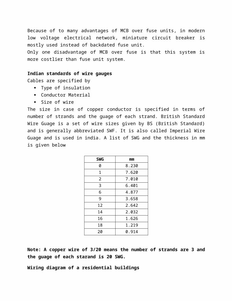
Indian standards of wire gaugesCables are specified by
Type of insulation Conductor Material Size of wire
The size in case of copper conductor is specified in terms of number of strands and the guage of each strand. British Standard Wire Guage is a set of wire sizes given by BS (British Standard) and is generally abbreviated SWF. It is also called Imperial Wire Guage and is used in india. A list of SWG and the thickness in mm is given below
SWG mm0 8.2301 7.6202 7.0103 6.4016 4.8779 3.65812 2.64214 2.03216 1.62618 1.21920 0.914
Note: A copper wire of 3/20 means the number of strands are 3 and the guage of each starand is 20 SWG.
Wiring diagram of a residential buildings
The wiring diagram gives the layout of the appliances and the way in which they are connected.
Following are the points to be considered during wiring installations.
1. Protective fuses and switches should be connected in live wires2. Tapping’s are not allowed except in ceiling rose, boards and junctions.3. Supply should be given to energy meter from service mains4. Separate circuit should be drawn for lighting and heating from mains5. For lighting, each circuit should not consists of more than 10 points or 800 watts.6. For lighting circuits, 5 Amp outlet should be used.7. For heating circuits, 15 Amp out lets should be used.8. Separate earthings set should be provided for heating circuits.9. For illuminating 1Sq meter area 10Watt electrical power is considered.10. Each ceiling fan is to be rated as 140 Watts.
SPECIFICATION TABLE
Wiring Layout of a resident plan of a 1 hall, 2 Bed room, 1 kitchen, 1 Bathroom, ! Verandah, and 1 Office.
++

LIGHTING SOURCES
INCANDESCENT LAMP
Figure below illustrates the basic working components that enable these sources to function. Very simply, electricity is passed through an engineered metal filament. As with many materials, the metal filament “resists” the flow of electricity, this resistance causes friction, which, in turn, becomes heat. Once this resistance and subsequent heat become great enough, the metal filament “incandesces”; it gives off radiant energy in a broad spectrum that includes the visible spectrum. Understanding that the radiant energy given off also includes a huge quantity of heat (infra-red radiation) explains many of the undesirable properties and inefficiencies of the incandescent sources.
Figure: Components of Incandescent Lamp
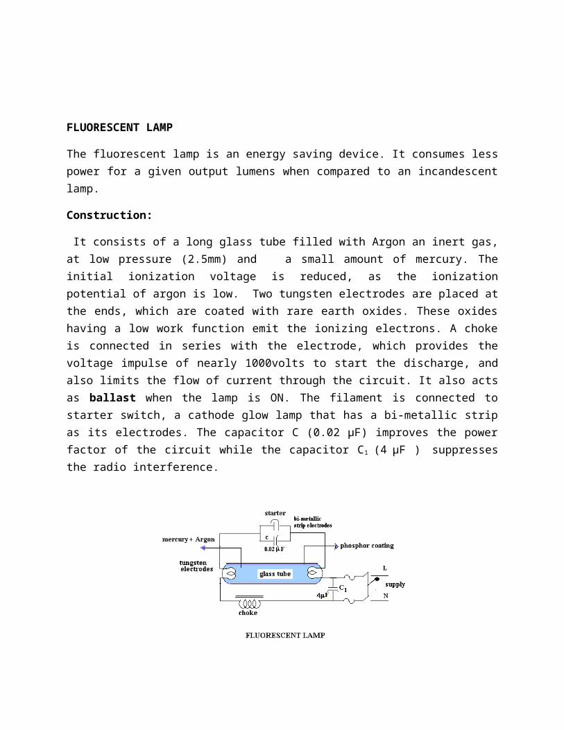
FLUORESCENT LAMP
The fluorescent lamp is an energy saving device. It consumes less power for a given output lumens when compared to an incandescent lamp.
Construction:
It consists of a long glass tube filled with Argon an inert gas, at low pressure (2.5mm) and a small amount of mercury. The initial ionization voltage is reduced, as the ionization potential of argon is low. Two tungsten electrodes are placed at the ends, which are coated with rare earth oxides. These oxides having a low work function emit the ionizing electrons. A choke is connected in series with the electrode, which provides the voltage impulse of nearly 1000volts to start the discharge, and also limits the flow of current through the circuit. It also acts as ballast when the lamp is ON. The filament is connected to starter switch, a cathode glow lamp that has a bi-metallic strip as its electrodes. The capacitor C (0.02 μF) improves the power factor of the circuit while the capacitor C1 (4 μF ) suppresses the radio interference.
Working:
When the switch is closed the supply voltage comes across the starter electrodes initiating a glow discharge between them. This heats the bi-metallic strip electrodes, which expand and make contact completing the circuit. The resulting current flows through the tungsten electrodes and the electrons are emitted from the oxide coating (low work function), which initiate ionization of the gas molecules present in the glass tube. At this instant the bi-metallic strip electrodes cool and the starter opens. Thus there is a sudden interruption of the current, which induces a high voltage (`@1000volts) in the choke.
This impulse strikes an arc between the electrodes lighting the lamp. The vaporized mercury gets ionized and emits radiations partly in the visible range and partly in ultraviolet range. The phosphor coating gives the required color and also absorbs the ultra violet light and re-radiates in the visible spectrum.

SODIUM VAPOR LAMP
Sodium vapor lamps are mainly used for street lighting. They have low luminosity hence require glass tubes of large lengths, which makes them quiet bulky.
Construction:
The lamp consists of a U shaped inner glass tube filled with neon gas at a pressure of 10mm. It also contains a small quantity of sodium and argon gas. The initial ionization voltage is reduced, as the ionization potential of argon is low. Two oxide coated tungsten electrodes are sealed into the tube at the ends. This tube is enclosed in an outer double walled vacuum enclosure to maintain the required temperature.
Working:
A voltage of the order of 380- 450 volts (depending on the wattage) is necessary to start the discharge, which is obtained from a high reactance transformer or an autotransformer. Initially the sodium vapor lamp operates as a low-pressure neon lamp emitting pink color. As the lamp gets heated and reaches a temperature of 200° C the sodium deposited on the sides of the tube walls vaporizes and radiates yellow light. It has a maximum efficiency at 220° C. Proper mounting of the lamp is to be ensured to prevent the sodium blackening the inner walls of the tube .A capacitor C is used to improve the power factor.

COMPACT FLUORESCENT LAMP
CFLs produce light differently than incandescent bulbs. In an incandescent, electric current runs through a wire filament and heats the filament until it starts to glow. In a CFL, an electric current is driven through a tube containing argon and a small amount of mercury vapor. This generates invisible ultraviolet light that excites a fluorescent coating (called phosphor) on the inside of the tube, which then emits visible light.CFLs need a little more energy when they are first turned on, but once the electricity starts moving, CFLs use about 70% less energy than incandescent bulbs. A CFL’s ballast helps "kick start" the CFL and then regulates the current once the electricity starts flowing.This entire process typically takes 30 seconds to 3 minutes to complete, which is why CFLs take longer than other lights to become fully lit. CFLs with decorative covers like globe or reflector shapes have a unique design challenge that results in the tradeoff of a slower warm up time, which is why these CFLs take longer than bare spirals to reach full brightness.Older CFLs used large and heavy magnetic ballasts that caused a buzzing noise in some bulbs. Most CFLs today — and all ENERGY STAR certified CFLs — use electronic ballasts, which do not buzz or hum.

LED LAMPS
LEDs create light by electroluminescence in a semiconductor material. Electroluminescence is the phenomenon of a material emitting light when electric current or an electric field is passed through it - this happens when electrons are sent through the material and fill electron holes. An electron hole exists where an atom lacks electrons (negatively charged) and therefore has a positive charge. Semiconductor materials like germanium or silicon can be "doped" to create and control the number of electron holes. Doping is the adding of other elements to the semiconductor material to change its properties. By doping a semiconductor you can make two separate types of semiconductors in the same crystal. The boundary between the two types is called a p-n junction. The junction only allows current to pass through it one way, this is why they are used as diodes. LEDs are made using p-n junctions. As electrons pass through one crystal to the other they fill electron holes. They emit photons (light).
Decorative Series lighting
Decorative vehicle lighting is lighting which is intended entirely as an decorative or ornamental addition to a Buildings or vehicle, rather than lighting which is required for safety.

Non-Conventional Energy
Definition of Renewable and non renewable Energy Systems:-
Energy is the capacity to do work. A plenty of energy is needed to sustain industrial growth and agricultural production.
Based upon nature, energy sources are classified as
1. Renewable / Non-conventional energy sources are inexhaustible and are renewed by nature itself. Solar, wind, tidal and biomass are few examples.
2. Non-renewable/ Conventional energy sources are exhaustible within a definite period of time depending upon its usage. Fossil fuels (coal, oil, gas) and nuclear fuels are few examples.
Different types of Conventional Energy systems with block diagram approach( Hydel , Thermal , Nuclear)
Hydel Power Plant:-
Generation of electricity by using the force of falling water is called hydro electricity or hydel power. It is cheaper than thermal or nuclear power. Dams are built to store water at a higher level; which is made to fall to rotate turbines that generate electricity.
The basic principle behind hydropower energy is the damming of rivers to create artificial in waterfalls, sometimes natural waterfalls are also used. The falling water is used to turn the turbines that drive electrical generators.
The different parts of hydroelectric power plant are
1. DamDams are structures built over rivers to stop the water flow and form a reservoir.The reservoir stores the water flowing down the river. This water is diverted to turbines in power stations. The dams collect water during the rainy season and stores it, thus allowing for a steady flow through the turbines throughout the year. Dams are also used for controlling floods and irrigation. The dams should be water-tight and should be able to withstand the pressure exerted by the water on it. There are different types of dams such as arch dams, gravity dams and buttress dams. The height of water in the dam is called head race.
2. SpillwayA spillway as the name suggests could be called as a way for spilling of water from dams. It is used to provide for the release of flood water from a dam. It is used to prevent over toping of the dams which could result in damage or failure of dams. Spillways could be controlled type or uncontrolled type. The uncontrolled types start releasing water upon water rising above a particular level. But in case of the controlled type, regulation of flow is possible.
3. Penstock and TunnelPenstocks are pipes which carry water from the reservoir to the turbines inside power station.

They are usually made of steel and are equipped with gate systems.Water under high pressure flows through the penstock. A tunnel serves the same purpose as a penstock. It is used when an obstruction is present between the dam and power station such as a mountain.
4. Surge TankSurge tanks are tanks connected to the water conductor system. It serves the purpose of reducing water hammering in pipes which can cause damage to pipes. The sudden surges of water in penstock is taken by the surge tank, and when the water requirements increase, it supplies the collected water thereby regulating water flow and pressure inside the penstock.
5. Power StationPower station contains a turbine coupled to a generator (see the cross section of a power house on the left). The water brought to the power station rotates the vanes of the turbine producing torque and rotation of turbine shaft. This rotational torque is transferred to the generator and is converted into electricity. The used water is released through the tail race. The difference between head race and tail race is called gross head and by subtracting the frictional losses we get the net head available to the turbine for generation of electricity.
ADVANTAGES:
1. No fuel charges.2. Less supervising staff is required.3. Maintenance and operation charges are very low.4. Running cost of plant is low.5. The plant efficiency does not change with age.6. It takes few minutes to run and synchronize the plant.7. No fuel transportation is required.8. No ash and flue gas problem and does not pollute the atmosphere.9. These plants are used for flood control and irrigation purpose.10. Long life in comparison with thermal and nuclear power plants.
DISADVANTAGES:-
1. The initial cost of power plant is very high.2. Takes long time for construction of dam.3. The plants are located in hilly areas far away from load center and thus they require long
transmission lines and losses in them will be more.4. Power generation by this plant is only dependant on natural phenomenon of rain. Therefore at
the time of drought or summer season the hydro power plant will not work.
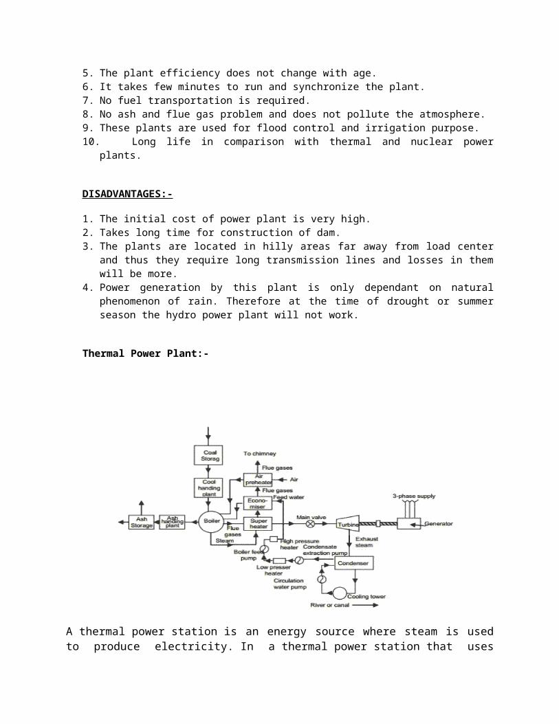
Thermal Power Plant:-

A thermal power station is an energy source where steam is used to produce electricity. In a thermal power station that uses coal, the fossil fuel is burned. This is done because the coal contains chemical energy that will produce heat. The burning of the coal and the production of heat occur under a boiler, which is a container with a large amount of water. When the water is heated, stream is created, which results in thermal energy. he thermal energy is contained so that there are high levels of pressure. When something is under pressure, it will readily escape through an opening if an opening is provided. In this case, the route of escape is through a turbine, which is basically a large fan. As the pressurized thermal energy passes through the turbine, it spins, creating mechanical energy.There is a path that connects the turbine to a generator. The mechanical energy of the spinning turbine makes power for the generator, which is then connected to distribution framework, allowing electrical energy to be distributed from the thermal power station to the masses. The stream that passed through the turbine is routed into a condenser, where it is cooled. The cooling of the steam allows it to change forms and become water again. When this happens, the water is returned to the boiler, forming a cyclical process.
There are four main circuits in any thermal power plant and these are1. Coal & Ash Circuit
This circuit deals mainly with feeding the boiler with coal for combustion purposes and taking care of the ash that is generated during the combustion process and includes equipment and paraphernalia that is used to handle the transfer and storage of coal and ash.
2. Air & Gas Circuit We know that air is one of the main components of the fire triangle and hence necessary for combustion. Since lots of coal is burnt inside the boiler it needs a sufficient quantity of air which is supplied using either forced draught or induced draught fans. The exhaust gases from the combustion are in turn used to heat the ingoing air through a heat exchanger before being let off in the atmosphere. The equipment which handles all these processes fall under this circuit.
3. Feed Water & Steam Circuit

This section deals with supplying of steam generated from the boiler to the turbines and to handle the outgoing steam from the turbine by cooling it to form water in the condenser so that it can be reused in the boiler plus making good any losses due to evaporation etc.
4. Cooling Water Circuit This part of the thermal power plant deals with handling of the cooling water required in the system. Since the amount of water required to cool the outgoing steam from the boiler is substantial, it is either taken from a nearby water source such as a river, or it is done through evaporation if the quantity of cooling water available is limited.
ADVANTAGES:-
1. Economical for low initial cost other than any generating plant.2. Land required less than hydro power plant.3. Since coal is main fuel & its cost is quite cheap than petrol/diesel so generation cost is
economical.4. Easy maintenance.5. Thermal power plant can be installed in any location where transportation & bulk of water are
available.
DISADVANTAGES:-
1. The running cost for a thermal power station is comparatively high due to fuel, maintenance etc.2. Large amount of smoke causes air pollution. The thermal power station is responsible for Global
warming.3. The heated water that comes from thermal power plant has an adverse effect on the lives in the
water and disturbs the ecology.4. Overall efficiency of thermal power plant is low less than 30%.
Nuclear Power Plant:-

The nuclear power station consists of the following components
1. FuelUranium is the basic fuel. Usually pellets of uranium oxide (UO2) are arranged in tubes to form fuel rods. The rods are arranged into fuel assemblies in the reactor core.
2. ModeratorMaterial in the core which slows down the neutrons released from fission so that they cause more fission. It is usually water, but may be heavy water or graphite.
3. Control rodsThese are made with neutron-absorbing material such as cadmium, hafnium or boron, and are inserted or withdrawn from the core to control the rate of reaction, or to halt it. If not controlled, the chain reaction become violent and can damage the reactor.
4. CoolantThe function of the coolant is to carry away the heat from the reactor to the heat exchanger for raising steam. The coolant may be ordinary water, heavy water, liquid sodium or gas like helium. The hot coolant circulates in a closed circuit between the reactor and heat exchanger.
5. Steam generatorThe steam raised in this is made to drive a steam turbine which is coupled to an alternator that generates electrical power. After driving the turbine , the used steam is condensed to water by the condenser and sent back to the heat exchanger with the help of feed water pump as shown. From there, it is pumped back to the reactor with the help of the circulating pump.
ADVANTAGES:-
1. The amount of uranium fuel required is very small. It is found that 30 gram of uranium has roughly the same energy output as the burning of 100 tonnes of coal.
2. Needs less space as compared to other power stations.3. Energy cost per unit is much lower.

4. It is reliable source of energy because fuel sources are abundant.
DISADVANTAGES:-
1. Uranium fuel is very costly.2. Initial cost of the plant is high.3. It requires protective system to contain pollution.4. Disposal of radioactive waste is a big problem.
Wind Power Plant:-
Wind is air in motion. It is the result of the conversion of the potential energy of the atmosphere into kinetic energy due to pressure differential.
The major components of a typical wind energy conversion system include a wind turbine, generator, interconnection apparatus and control systems, as shown in the above figure.
1. Wind turbines Turbines can be classified into the vertical axis type and the horizontal axis type. Most modern wind turbines use a horizontal axis configuration with two or three blades, operating either down-wind or up-wind. A wind turbine can be designed for a constant speed or variable speed operation. Variable speed wind turbines can produce 8% to 15% more energy output as compared to their constant speed counterparts.
2. GeneratorMost turbine manufacturers have opted for reduction gears between the low speed turbine rotor and the high speed three-phase generators. Direct drive configuration, where a generator is coupled to the rotor of a wind turbine directly, offers high reliability, low maintenance, and

possibly low cost for certain turbines. Several manufacturers have opted for the direct drive configuration in the recent turbine designs. At the present time and in the near future, generators for wind turbines will be synchronous generators, permanent magnet synchronous generators, and induction generators, including the squirrel cage type and wound rotor type. For small to medium power wind turbines, permanent magnet generators and squirrel cage induction generators are often used because of their reliability and cost advantages. Induction generators, permanent magnet synchronous generators and wound field synchronous generators are currently used in various high power wind turbines.
3. Interconnection apparatuses and Control SystemThese are the devices used to achieve power control, soft start and interconnection functions. Very often, power electronic converters such as rectifiers and inverters are used as such devices. Most modern turbine inverters are forced commutated PWM inverters to provide a fixed voltage and fixed frequency output with a high power quality. Both voltage source voltage controlled inverters and voltage source current controlled inverters have been applied in wind turbines. For certain high power wind turbines, effective power control can be achieved with double PWM (pulse width modulation) converters which provide a bi-directional power flow between the turbine generator and the utility grid.
ADVANTAGES:-
1. Wind energy is a renewable source of energy. 2. Wind energy is a green energy source and does not cause pollution.3. The potential of wind power is enormous – 20 times more than what the entire human
population needs.4. Wind turbines are incredible space-efficient. The largest of them generate enough electricity to
power 600 U.S. homes.5. Prices have decreased over 80% since 1980 and are expected to keep decreasing.6. The operational costs associated with wind power are low.7. Good domestic potential: Residential wind turbines yields energy savings and protects
homeowners from power outages.
DISADVANTAGES:-
1. Wind is a fluctuating (intermittent) source of energy and is not suited to meet the base load energy demand unless some form of energy storage is utilized (e.g. batteries, pumped hydro).
2. The manufacturing and installation of wind turbines requires heavy upfront investments – both in commercial and residential applications.

3. Wind turbines can be a threat to wildlife (e.g. birds, bats).4. Noise is regularly reported as a problem by neighboring homes.5. How wind turbines look (aesthetics) is a legitimate concern for some people.
Solar Power Plant:-
Rising energy costs and increasing support for clean, renewable energy sources has made solar power a growth industry. Solar panels directly generate power by converting sunlight to electricity with no moving parts, zero emissions, and little to no maintenance.
Solar power systems can be either independent (off-grid) or connected to the utility power grid. In the off-grid model, battery packs are used to store electrical power for night usage or peak consumption periods. Independent systems may also be used by telecommunications providers or satellite TV broadcasters, and can be combined with wind power or micro-hydropower resources in a mixed power generation station.
A typical solar system consists of solar panels, a controller, energy storage and an inverter for conversion of DC to AC, and the block diagram shows how the solar power generator can be connected to the power grid .
1. Solar panelsTo maximize the light exposure over the solar panels they are usually installed in open fields or in elevated locations (e.g., rooftops of buildings). These installations can make solar power generation systems vulnerable to transients, such as ring-wave and lightning, as well as coupled transients from adjacent cables like power/control lines in the same conduit. The cable of each solar panel in the solar power system is first connected to the header box of the solar system controller.

2. Controller and Inverter ProtectionThe power output generated by the solar panels can vary depending on light levels received due to clouds or other types of shading effects. One example is when the sun traverses the horizon and shade from trees or structures prevents light from striking the entire array, causing droops in power levels received by the controllers and inverters. Controllers and inverters are susceptible to many types of transients. Electrostatic discharge (ESD) sources include human, open air or a phenomenon of transients that are generated from the glass of the solar panels and discharged into the controller and inverters. Coupled transients like EFT (electrical fast transient) and ringwave, and lightning, whether by direct or indirect (close proximity) hits, can also generate transients. Communications ports on controllers and inverters are susceptible to these transients.
3. Battery Pack ProtectionIn solar power systems the safety of the battery pack is a very important design consideration. Both lead acid and lithium batteries that are integrated into the system or installed with an external wire connection can be affected by potential failures such as cable short circuit, misconnection of the battery’s positive and negative poles, or over temperature issues.
ADVANTAGES:-
1. Renewable source of energy2. Pollution free3. After the capital cost, the cost of power generation is quite low4. Wide range of applications, powering street lights to satellites
DISADVANTAGES:-
1. Capital cost is very high2. Large area of land is required3. Large number of solar panels are required 4. Affected by seasons.
Comparison of conventional and non conventional Energy Sources
Conventional Sources of Energy
1. The sources of energy which have been in use for a long time, e.g., coal, petroleum, natural gas and water power.
2. They are exhaust able except water.3. They cause pollution when used, as they emit smoke and ash.4. They are very expensive to be maintained, stored and transmitted as they are carried over
long distance through transmission grid and lines.
Non-Conventional Sources of Energy
1. The resources which are yet in the process of development over the past few years. It includes solar, wind, tidal, biogas, and biomass, geothermal.
2. They are inexhaustible.3. They are generally pollution free.4. Less expensive due to local use and easy to maintain.
1
Write a brief note for the following(i) Synchronisation of alternator(ii) Advantages of CFL lamp.
2 State a few advantages of solar energy. Also explain the structure of a solar photovoltaic cell.
3
What is the purpose of earthing in electrical appliances? Explain the plate earthing method.
4 With a neat sketch show the wiring diagram of the residential building.5 What is earthing ? Why is it necessary ? Explain the plate earthing. 6 Distinguish between Fuses and MCB7