wireless measurement electronics for passive temperature ... · sardini and serpelloni:wireless...
TRANSCRIPT

2354 IEEE TRANSACTIONS ON INSTRUMENTATION AND MEASUREMENT, VOL. 61, NO. 9, SEPTEMBER 2012
Wireless Measurement Electronics for PassiveTemperature Sensor
Emilio Sardini, Member, IEEE, and Mauro Serpelloni, Member, IEEE
Abstract—High-temperature measurement systems do not al-low the use of traditional measurement techniques. In the pres-ence of high temperatures, the proper functioning of electronicsis compromised. Furthermore, if the measurement environmentis also hermetic, the traditional cabled measurement techniquecannot be adopted. In this paper, a system composed by a passivesensor placed in the harsh environment and a dedicated readoutelectronics placed outside in a safe zone is designed and proposedfor measuring the temperature up to 330 ◦C. The sensing ele-ment is based on a hybrid sensor constituted solely by passivecomponents (an inductor connected to a planar micromachinedvariable capacitor). The hybrid sensor can be placed inside high--temperature and hermetic measuring environment, while thetemperature data can be measured telemetrically by an externalreading unit, located in the safe environment. In this paper, thesystem is presented using novel electronic circuits of the readoutunit, which permit to avoid the need of an expensive commercialimpedance analyzer. The wireless measurement electronics wasdesigned and characterized; the results obtained and reported inthis paper are quite in good agreement with those measured by areference commercial impedance analyzer. The complete measure-ment system is presented as a viable solution to the measurementof high temperatures in harsh or enclosed industrial environments.
Index Terms—Autonomous sensor, contactless telemetric sys-tem, high-temperature measurement, microelectromechanical sys-tems (MEMS), wireless system.
I. INTRODUCTION
IN INDUSTRIAL environments, high-temperature measure-ments are required for process control, safety evaluation, re-
liability prediction, product liability, and quality control. Sincethe measurement environment is harsh, it is insulated fromthe external side where the control or processing electronicsis placed. Furthermore, in several applications such as in con-trolled drying processes and pressurized fluids, the environmentmust be hermetic as well. In these cases, the environment iscommonly unsuitable for electronic active circuits since they donot work in the presence of temperatures greater than 100 ◦C,thus excluding the possibility of using commonly known wire-less sensor network. Moreover, most existing temperature sen-sors cannot be used since they require a cabled solution. The
Manuscript received April 6, 2011; revised January 2, 2012; acceptedFebruary 14, 2012. Date of publication June 1, 2012; date of current versionAugust 10, 2012. The Associate Editor coordinating the review process for thispaper was Dr. Deniz Gurkan.
The authors are with the Department of Information Engineering, Univer-sity of Brescia, 25123 Brescia, Italy (e-mail: [email protected];[email protected]).
Color versions of one or more of the figures in this paper are available onlineat http://ieeexplore.ieee.org.
Digital Object Identifier 10.1109/TIM.2012.2199189
solution is to measure high temperatures without contact. Incontactless techniques, the sensing element is positioned in theharsh environment, while the second part of the measurementsystem, consisting of the active devices of the conditioningelectronics required to extract the measurement information,is outside in a safe zone. In the literature, several examplesof contactless measurements are reported using optical sensors[1]–[4]. Optical instruments such as pyrometers or infrared (IR)optical sensors sometimes offer a solution. In [3], an IR tem-perature measurement system able to measure between 500 ◦Cand 1300 ◦C is described. In [4], the authors propose the useof microwave radiometry to noninvasively measure and controlthe temperature during the microwave sintering processes. Adifferent measurement approach is described in [5]; the authorspresent a contactless magnetic measurement solution: NiFesensors, whose properties are very sensitive to temperature, areassociated to remote magnetic transducers, and the active part isplaced outside. In [6], surface-acoustic-wave sensors for high-temperature applications are analyzed highlighting the materialissues: The high-temperature characteristics of novel devicesare investigated by finite-element simulation and by experi-mental deformation analysis. Assembly, interconnection, andpackaging techniques are also discussed. In [7], materials andpackaging solution for microsensors, systems, and devices forhigh-temperature and harsh environment are analyzed and com-pared. In [8], silicon carbide microelectromechanical systems(MEMS) are proposed for harsh environment measurements;in the paper, there is a discussion of silicon carbide MEMSas high-temperature sensors. Among the contactless systems,autonomous sensors are an interesting solution for connectingthe probe positioned in the hazardous zone with the condi-tioning electronics in the safe zone. They represent a viablesolution when the measurement environment is contained in anenclosed and hermetic space and the required wire link throughthe separating wall, between the harsh and safe zones, is notpossible due to the presence of high pressure or to the use ofexpensive connecting techniques. Usually, sensing techniquesare based on a change of the resonant frequency of an LCcircuit. In the literature, examples of such systems are reportedin [9]–[13]. In [13], a passive wireless temperature sensor oper-ating in harsh environment for high-temperature (up to 235 ◦C)rotating component monitoring is reported. Contactless mea-surement techniques require also the use of special electronicsystems. Several of these are based on frequency analysis or onimpedance variation. In the literature, different proposals arereported in order to design ad hoc instruments for the applica-tions. The design of electronic circuits for impedance analysisand scanning frequency can be developed in different ways,
0018-9456/$31.00 © 2012 IEEE

SARDINI AND SERPELLONI: WIRELESS MEASUREMENT ELECTRONICS FOR PASSIVE TEMPERATURE SENSOR 2355
with a field-programmable-gate-array approach [14], [15] orwith an impedance analyzer [16], [17]. In [17], the impedancemeasurement instrumentation is based on the measurement ofthe real and the imaginary part of impedance, working in thefrequency from 10 to 100 kHz. In [18], the authors describe animpedance gain-phase analyzer; the instrument operates in thefrequency range of 10 Hz–200 kHz.
In this paper, the authors propose a complete wirelessmeasurement system of temperature up to 330 ◦C inside high-temperature and/or hermetic environment. Two papers previ-ously published describe the adopted hybrid sensor. In [19]and [20], a novel temperature sensor composed by a hybridMEMS is described and characterized. The sensor measureshigh temperatures in harsh industrial environments. The hybridMEMS is composed by a planar inductor developed in thick-film technology and a micromachined variable capacitor thatis temperature sensitive [21]. In [19] and [20], an expensivecommercial impedance amplifier was used to measure themodule and phase of the impedance at the terminals of a readoutinductor placed in a safe zone. In [22], a novel high-temperaturemeasurement system composed by the hybrid MEMS as thetemperature sensor and a contactless front-end electronic isbriefly described. The electronic circuits implement a tele-metric technique, avoiding the need of an expensive commer-cial impedance amplifier. In this paper, the proposed wirelessmeasurement system is widely described; important aspectsabout how it has been designed, implemented, and tested arereported. Particular attention is given to the aspects of designand testing of the developed electronic circuits. The electronicsis based on a measurement technique called three-resonancemethod [19]. The distance between the sensor and reader canbe constant if the telemetric system is fixed with the measuringchamber; otherwise, the measurement system consists of thesensor placed in the oven and a mobile unit outside. Theproposed system is capable of operating in both situations.To experimentally verify the characteristics of the proposedmeasurement system, a temperature-controlled measurementoven has been developed. In this paper, a comparison betweenthe developed circuits and a commercial impedance analyzer isperformed. The analysis shows that the proposed circuits allowthe measurement of the frequencies in a satisfactory manner,permitting a good telemetric measurement of the temperatureup to 330 ◦C.
II. DESCRIPTION OF THE TEMPERATURE
MEASUREMENT SYSTEM
The proposed telemetric system is shown schematically inFig. 1: On the left, the hybrid MEMS is placed into the harshenvironment, while on the right, the readout unit is in the safezone. A wall separates the two zones, and the two subsystemscommunicate through an inductive coupling. This wall must becomposed of nonmagnetic and nonconductive material so thatthe magnetic coupling is guaranteed.
A. Hybrid MEMS
The hybrid MEMS placed in the harsh environment iscomposed by a microfabricated temperature-sensitive variable
Fig. 1. Block diagram of the telemetric system.
Fig. 2. Pictures of the hybrid MEMS.
Fig. 3. Microscope picture of the bent beam.
capacitor fabricated using the MetalMUMPs process [21] anda planar inductor with high-temperature characteristics devel-oped in thick-film process (see Fig. 2). The hybrid MEMSbehaves as an LC resonant circuit, where the capacitance isthe micromachined variable capacitor and the inductance is theplanar inductor. The layout of the variable capacitor is orga-nized in 36 cells having capacitive behavior and connectedin parallel. The interdigitated capacitor is made by two struc-tures named A and B in Fig. 3. The thermal expansiongenerates a relative movement of the A-structure and theB-structure, varying the capacitance. The maximum operatingtemperature is limited by the maximum operating limit ofnickel (350 ◦C). The single cell (see Fig. 3) is based on acascade of three bent beam structures. The planar inductoris obtained using thick-film technology by screen printingand microcutting by a laser. During the screen printing, twoconductive (QM14 commercialized by DuPont) films, oneoverlapping the other, were deposited to reach a thickness of
2356 IEEE TRANSACTIONS ON INSTRUMENTATION AND MEASUREMENT, VOL. 61, NO. 9, SEPTEMBER 2012
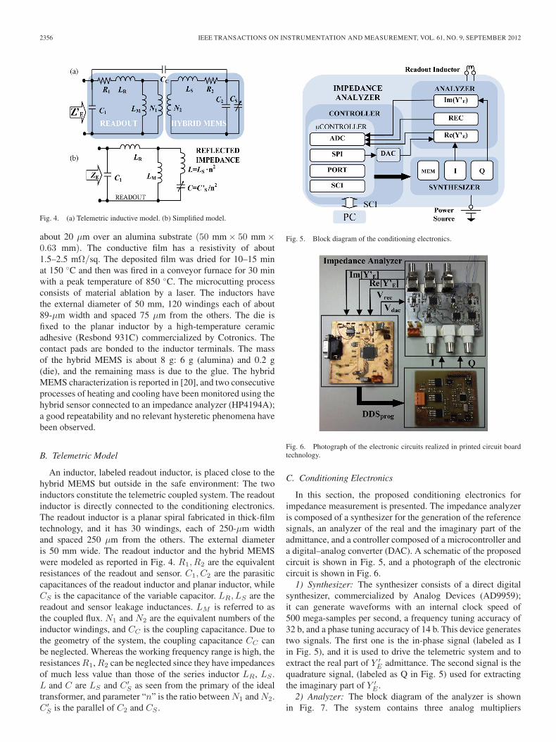
Fig. 4. (a) Telemetric inductive model. (b) Simplified model.
about 20 μm over an alumina substrate (50 mm × 50 mm ×0.63 mm). The conductive film has a resistivity of about1.5–2.5 mΩ/sq. The deposited film was dried for 10–15 minat 150 ◦C and then was fired in a conveyor furnace for 30 minwith a peak temperature of 850 ◦C. The microcutting processconsists of material ablation by a laser. The inductors havethe external diameter of 50 mm, 120 windings each of about89-μm width and spaced 75 μm from the others. The die isfixed to the planar inductor by a high-temperature ceramicadhesive (Resbond 931C) commercialized by Cotronics. Thecontact pads are bonded to the inductor terminals. The massof the hybrid MEMS is about 8 g: 6 g (alumina) and 0.2 g(die), and the remaining mass is due to the glue. The hybridMEMS characterization is reported in [20], and two consecutiveprocesses of heating and cooling have been monitored using thehybrid sensor connected to an impedance analyzer (HP4194A);a good repeatability and no relevant hysteretic phenomena havebeen observed.
B. Telemetric Model
An inductor, labeled readout inductor, is placed close to thehybrid MEMS but outside in the safe environment: The twoinductors constitute the telemetric coupled system. The readoutinductor is directly connected to the conditioning electronics.The readout inductor is a planar spiral fabricated in thick-filmtechnology, and it has 30 windings, each of 250-μm widthand spaced 250 μm from the others. The external diameteris 50 mm wide. The readout inductor and the hybrid MEMSwere modeled as reported in Fig. 4. R1, R2 are the equivalentresistances of the readout and sensor. C1, C2 are the parasiticcapacitances of the readout inductor and planar inductor, whileCS is the capacitance of the variable capacitor. LR, LS are thereadout and sensor leakage inductances. LM is referred to asthe coupled flux. N1 and N2 are the equivalent numbers of theinductor windings, and CC is the coupling capacitance. Due tothe geometry of the system, the coupling capacitance CC canbe neglected. Whereas the working frequency range is high, theresistances R1, R2 can be neglected since they have impedancesof much less value than those of the series inductor LR, LS .L and C are LS and C ′
S as seen from the primary of the idealtransformer, and parameter “n” is the ratio between N1 and N2.C ′
S is the parallel of C2 and CS .
Fig. 5. Block diagram of the conditioning electronics.
Fig. 6. Photograph of the electronic circuits realized in printed circuit boardtechnology.
C. Conditioning Electronics
In this section, the proposed conditioning electronics forimpedance measurement is presented. The impedance analyzeris composed of a synthesizer for the generation of the referencesignals, an analyzer of the real and the imaginary part of theadmittance, and a controller composed of a microcontroller anda digital–analog converter (DAC). A schematic of the proposedcircuit is shown in Fig. 5, and a photograph of the electroniccircuit is shown in Fig. 6.
1) Synthesizer: The synthesizer consists of a direct digitalsynthesizer, commercialized by Analog Devices (AD9959);it can generate waveforms with an internal clock speed of500 mega-samples per second, a frequency tuning accuracy of32 b, and a phase tuning accuracy of 14 b. This device generatestwo signals. The first one is the in-phase signal (labeled as Iin Fig. 5), and it is used to drive the telemetric system and toextract the real part of Y ′
E admittance. The second signal is thequadrature signal, (labeled as Q in Fig. 5) used for extractingthe imaginary part of Y ′
E .2) Analyzer: The block diagram of the analyzer is shown
in Fig. 7. The system contains three analog multipliers

SARDINI AND SERPELLONI: WIRELESS MEASUREMENT ELECTRONICS FOR PASSIVE TEMPERATURE SENSOR 2357
Fig. 7. Block diagram of the analyzer.
(Intersil HA2556), each of four-quadrant type, and two passivelow-pass filters. The function of the circuit is to extract thereal and imaginary admittance components and identify theresonant frequencies for the measuring technique. A sinusoidalvoltage, whose amplitude and frequency are respectively regu-lated by VDAC and I, is applied to the telemetric system. Theinjected current is successively sent to the M2 multiplier sincethe other input of the multiplier is again the in-phase signal(I). The output of the low-pass filter is the real component ofthe voltage that is successively acquired by an analog–digitalconverter (ADC) and further processed by a microcontroller.Similarly, also the imaginary component has been obtainedby multiplying the voltage of the telemetric system with theQ signal. After the multiplication and the low-pass filter, theimaginary component is sampled by the ADC converter.
3) Controller: The controller is composed by a microcon-troller, commercialized by Freescale (MCF51AC256), and aDAC. The microcontroller integrates the Serial Peripheral In-terface and Serial Communication Interface (SCI) and at leastthree channels of 10-b ADC. The sampling time of the ADCcan be adjusted by programming the microcontroller’s specificregistries. Since the signal from the three channels is a contin-uous signal and the lower limit of the frequency of interest is1 MHz and considering that the change in temperature is a slowprocess, the sampling time was not considered a restrictive pa-rameter for the process. For the performed measurements, thistime is 2 ms for each frequency set, but this value can certainlybe lowered. The ADC samples the real (Re(Y ′
E)), imaginary(Im(Y ′
E)), and peak RECtifier (REC) of the telemetric voltage.The REC signal is the output of a full bridge diode Schottkyand is used by the microcontroller to regulate the amplitudeof the injecting current into the telemetric system. The aim isto avoid the saturation of the multiplier since the impedancemodule of the telemetric system has a wide dynamic. Themicrocontroller programs the synthesizer in order to sweepthe frequency from 1 to 10 MHz, and during this phase, themicrocontroller stores the sampled data into its internal memoryand, when the sweep has finished, starts the data processing.The number of samples acquired during measurement is anumber settable by user. After this process, the microcontrollersends the data to a personal computer (PC) through the SCI,
Fig. 8. Flowchart of measurement system.
and the PC analyzes the module and the phase of impedanceextracting the frequencies of interest required by the three-resonance method. In Fig. 8, the flow chart of the measurementsystem is represented. As it can be seen from the diagram, thevalue of Vrec is constantly monitored. The regulation by DACis then carried out automatically only when needed.
III. MEASUREMENT TECHNIQUE
Referring to the circuit shown in Fig. 4, ZE is calculated as(1) shown at the bottom of the page.
The impedance reported in (1) has three resonant frequen-cies. The first (fra) and the second resonant frequency (frb)are both influenced by C1 and C. The resonant frequency (fa)is influenced only by C, and it is more sensitive to C than theother two frequencies. Its expression is
fa =1
2π
√C ·
(L+ LMLR
LR+LM
) . (2)
fa depends on C and also on distance since the distancechanges the coupled and the leakage flux modifying the valueof LM , LR. The other two frequencies (fra and frb) have morecomplex dependence and are dependent also on the parasitic
ZE =s3 (LMLC + LRC(LM + L)) + s(LM + LR)
s4C1 (LMLC + LRC(LM + L)) + s2 (C1(LM + LR) + C(LM + L)) + 1(1)

2358 IEEE TRANSACTIONS ON INSTRUMENTATION AND MEASUREMENT, VOL. 61, NO. 9, SEPTEMBER 2012
capacitance of the readout inductor. If the two elements of thetelemetric system are fixed between the walls of the oven, thedistance does not change, and the sensor capacitance can beobtained from (2). Anyway, if the conditioning electronics ismounted over a mobile unit or the distance between the readoutand hybrid sensor changes for any reason, the changing of thedistance is compensated by the three-resonance method [19].This method is based on a parameter, called “F ,” whose valuedepends only on distance
F = (2πfra)2 + (2πfrb)
2 − (2πfa)2 =
1
C1
(LR + LML
LM+L
) .(3)
If C1 is fixed, “F ” depends only on coupled and leakagefluxes: These values are related only to the distance and notto the transducer capacitance. Moreover, the parameter “F ” isobtained by a direct measurement since it can be calculatedby elaborating the measurement of the three fra, frb, and fafrequencies. Introducing the following expressions:
L =LS · n2 (4)
C =C ′
S
n2(5)
L1 =LR + LM (6)
L2 =LS +LM
n2. (7)
Substituting (4)–(7) into (2) and in (3) and rearranging theexpressions, the ratio of (3) with (2) is equal to
F
(2πfa)2=
L2C′S
L1C1. (8)
Rearranging (8), a straightforward expression of the sensorcapacitance (C ′
S) is
C ′S =
L1C1
L2
F
(2πfa)2. (9)
C ′S is obtained as a product between a constant term and a
second one calculated from the three measured fra, frb, and fafrequencies. The constant term can be automatically obtainedfrom a calibration operation or can be calculated measuringthe equivalent circuit parameters of each single planar inductor:L1 and L2 are the self-inductances of the readout and sensinginductances, while C1 is the parasitic capacitance (or any otheradded capacitance) of the readout circuit. The equivalent circuitparameters of every single inductor separately (consisting in theseries of an inductance and a resistance both in parallel with acapacitance) have been measured by the impedance analyzerHP4194A, and their values are reported in Table I.
IV. MEASUREMENT ELECTRONIC
As previously reported, to calculate C’s, the measurement ofthe three resonant frequencies (fra, frb, fa) is required. Theseare the resonance frequencies of ZE and are frequency pointswhose phase is zero. The impedance measured to the readout
TABLE IEQUIVALENT CIRCUIT PARAMETERS
Fig. 9. Module and phase of the Z′E impedance.
Fig. 10. Frequency f ′ra, f
′a values and the error in the calculation of C′
s as afunction of the resistance.
terminals is Z ′E . Its diagram is reported in Fig. 9, where it is
possible to individuate three points f ′ra, f
′af
′rb that correspond
in succession from right to left to the first maximum and min-imum, respectively, while f ′
rb is the second maximum. Whenthe resistance components of the model (see Fig. 2) have zerovalue, the three resonant frequencies fra, fafrb and f ′
ra, f′af
′rb
respectively coincide. In the real case, the resistances of thereadout inductor and of the hybrid sensor have about 22 and80 Ω at 25 ◦C, respectively. Their values are also subjected tochange with temperature. In this case, f ′
ra, f′a does not coincide
with fra, fa. The error introduced in the calculation of C ′S using
f ′ra, f
′a instead of fra, fa has been estimated, and it is reported
in Fig. 10 as a function of the resistance values. The data havebeen obtained from Spice simulation. Physical models of thereadout inductor and hybrid sensor have been tuned up fromexperimental measurement. The simulation results are shown inFig. 10, where the values of f ′
ra, f′a are reported as a function of
the resistance. The values of fra, fa are 1.125 and 1.179 MHz.Approximately, the resistance values of the model represent-
ing the real system are 80 and 22 Ω, and considering the worst
SARDINI AND SERPELLONI: WIRELESS MEASUREMENT ELECTRONICS FOR PASSIVE TEMPERATURE SENSOR 2359
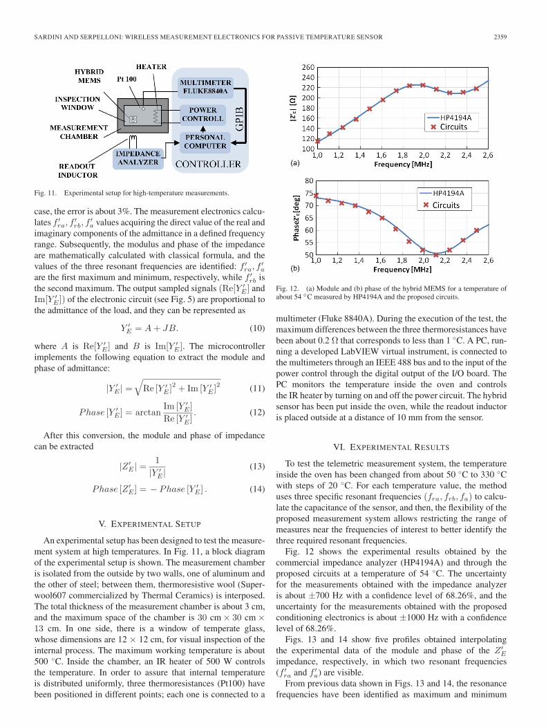
Fig. 11. Experimental setup for high-temperature measurements.
case, the error is about 3%. The measurement electronics calcu-lates f ′
ra, f′rb, f
′a values acquiring the direct value of the real and
imaginary components of the admittance in a defined frequencyrange. Subsequently, the modulus and phase of the impedanceare mathematically calculated with classical formula, and thevalues of the three resonant frequencies are identified: f ′
ra, f′a
are the first maximum and minimum, respectively, while f ′rb is
the second maximum. The output sampled signals (Re[Y ′E ] and
Im[Y ′E ]) of the electronic circuit (see Fig. 5) are proportional to
the admittance of the load, and they can be represented as
Y ′E = A+ JB. (10)
where A is Re[Y ′E ] and B is Im[Y ′
E ]. The microcontrollerimplements the following equation to extract the module andphase of admittance:
|Y ′E | =
√Re [Y ′
E ]2 + Im [Y ′
E ]2 (11)
Phase [Y ′E ] = arctan
Im [Y ′E ]
Re [Y ′E ]
. (12)
After this conversion, the module and phase of impedancecan be extracted
|Z ′E | =
1
|Y ′E |
(13)
Phase [Z ′E ] = − Phase [Y ′
E ] . (14)
V. EXPERIMENTAL SETUP
An experimental setup has been designed to test the measure-ment system at high temperatures. In Fig. 11, a block diagramof the experimental setup is shown. The measurement chamberis isolated from the outside by two walls, one of aluminum andthe other of steel; between them, thermoresistive wool (Super-wool607 commercialized by Thermal Ceramics) is interposed.The total thickness of the measurement chamber is about 3 cm,and the maximum space of the chamber is 30 cm × 30 cm ×13 cm. In one side, there is a window of temperate glass,whose dimensions are 12 × 12 cm, for visual inspection of theinternal process. The maximum working temperature is about500 ◦C. Inside the chamber, an IR heater of 500 W controlsthe temperature. In order to assure that internal temperatureis distributed uniformly, three thermoresistances (Pt100) havebeen positioned in different points; each one is connected to a
Fig. 12. (a) Module and (b) phase of the hybrid MEMS for a temperature ofabout 54 ◦C measured by HP4194A and the proposed circuits.
multimeter (Fluke 8840A). During the execution of the test, themaximum differences between the three thermoresistances havebeen about 0.2 Ω that corresponds to less than 1 ◦C. A PC, run-ning a developed LabVIEW virtual instrument, is connected tothe multimeters through an IEEE 488 bus and to the input of thepower control through the digital output of the I/O board. ThePC monitors the temperature inside the oven and controlsthe IR heater by turning on and off the power circuit. The hybridsensor has been put inside the oven, while the readout inductoris placed outside at a distance of 10 mm from the sensor.
VI. EXPERIMENTAL RESULTS
To test the telemetric measurement system, the temperatureinside the oven has been changed from about 50 ◦C to 330 ◦Cwith steps of 20 ◦C. For each temperature value, the methoduses three specific resonant frequencies (fra, frb, fa) to calcu-late the capacitance of the sensor, and then, the flexibility of theproposed measurement system allows restricting the range ofmeasures near the frequencies of interest to better identify thethree required resonant frequencies.
Fig. 12 shows the experimental results obtained by thecommercial impedance analyzer (HP4194A) and through theproposed circuits at a temperature of 54 ◦C. The uncertaintyfor the measurements obtained with the impedance analyzeris about ±700 Hz with a confidence level of 68.26%, and theuncertainty for the measurements obtained with the proposedconditioning electronics is about ±1000 Hz with a confidencelevel of 68.26%.
Figs. 13 and 14 show five profiles obtained interpolatingthe experimental data of the module and phase of the Z ′
E
impedance, respectively, in which two resonant frequencies(f ′
ra and f ′a) are visible.
From previous data shown in Figs. 13 and 14, the resonancefrequencies have been identified as maximum and minimum
2360 IEEE TRANSACTIONS ON INSTRUMENTATION AND MEASUREMENT, VOL. 61, NO. 9, SEPTEMBER 2012
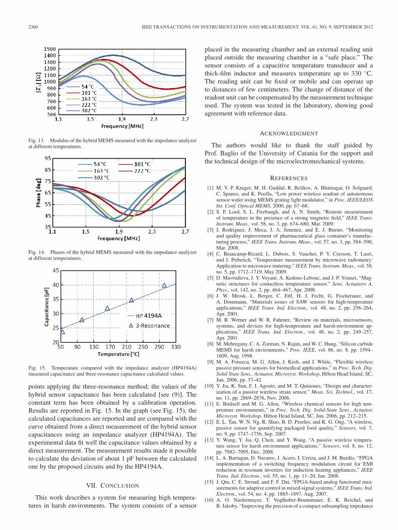
Fig. 13. Modulus of the hybrid MEMS measured with the impedance analyzerat different temperatures.
Fig. 14. Phases of the hybrid MEMS measured with the impedance analyzerat different temperatures.
Fig. 15. Temperature compared with the impedance analyzer (HP4194A)measured capacitance and three-resonance capacitance calculated values.
points applying the three-resonance method; the values of thehybrid sensor capacitance has been calculated [see (9)]. Theconstant term has been obtained by a calibration operation.Results are reported in Fig. 15. In the graph (see Fig. 15), thecalculated capacitances are reported and are compared with thecurve obtained from a direct measurement of the hybrid sensorcapacitances using an impedance analyzer (HP4194A). Theexperimental data fit well the capacitance values obtained by adirect measurement. The measurement results made it possibleto calculate the deviation of about 1 pF between the calculatedone by the proposed circuits and by the HP4194A.
VII. CONCLUSION
This work describes a system for measuring high tempera-tures in harsh environments. The system consists of a sensor
placed in the measuring chamber and an external reading unitplaced outside the measuring chamber in a “safe place.” Thesensor consists of a capacitive temperature transducer and athick-film inductor and measures temperature up to 330 ◦C.The reading unit can be fixed or mobile and can operate upto distances of few centimeters. The change of distance of thereadout unit can be compensated by the measurement techniqueused. The system was tested in the laboratory, showing goodagreement with reference data.
ACKNOWLEDGMENT
The authors would like to thank the staff guided byProf. Baglio of the University of Catania for the support andthe technical design of the microelectromechanical systems.
REFERENCES
[1] M. V. P. Kruger, M. H. Guddal, R. Belikov, A. Bhatnagar, O. Solgaard,C. Spanos, and K. Poolla, “Low power wireless readout of autonomoussensor wafer using MEMS grating light modulator,” in Proc. IEEE/LEOSInt. Conf. Optical MEMS, 2000, pp. 67–68.
[2] S. F. Lord, S. L. Firebaugh, and A. N. Smith, “Remote measurementof temperature in the presence of a strong magnetic field,” IEEE Trans.Instrum. Meas., vol. 58, no. 3, pp. 674–680, Mar. 2009.
[3] J. Rodriguez, J. Meca, J. A. Jimenez, and E. J. Bueno, “Monitoringand quality improvement of pharmaceutical glass container’s manufac-turing process,” IEEE Trans. Instrum. Meas., vol. 57, no. 3, pp. 584–590,Mar. 2008.
[4] C. Beaucamp-Ricard, L. Dubois, S. Vaucher, P. Y. Cresson, T. Lasri,and J. Pribetich, “Temperature measurement by microwave radiometry:Application to microwave sintering,” IEEE Trans. Instrum. Meas., vol. 58,no. 5, pp. 1712–1719, May 2009.
[5] D. Mavrudieva, J. Y. Voyant, A. Kedous-Lebouc, and J. P. Yonnet, “Mag-netic structures for contactless temperature sensor,” Sens. Actuators A,Phys., vol. 142, no. 2, pp. 464–467, Apr. 2008.
[6] J. W. Mrosk, L. Berger, C. Ettl, H. J. Fecht, G. Fischerauer, andA. Dommann, “Materials issues of SAW sensors for high-temperatureapplications,” IEEE Trans. Ind. Electron., vol. 48, no. 2, pp. 258–264,Apr. 2001.
[7] M. R. Werner and W. R. Fahrner, “Review on materials, microsensors,systems, and devices for high-temperature and harsh-environment ap-plications,” IEEE Trans. Ind. Electron., vol. 48, no. 2, pp. 249–257,Apr. 2001.
[8] M. Mehregany, C. A. Zorman, N. Rajan, and W. C. Hung, “Silicon carbideMEMS for harsh environments,” Proc. IEEE, vol. 86, no. 8, pp. 1594–1609, Aug. 1998.
[9] M. A. Fonseca, M. G. Allen, J. Kroh, and J. White, “Flexible wirelesspassive pressure sensors for biomedical applications,” in Proc. Tech. Dig.Solid State Sens., Actuator, Microsyst. Workshop, Hilton Head Island, SC,Jun. 2006, pp. 37–42.
[10] Y. Jia, K. Sun, F. J. Agosto, and M. T. Quinones, “Design and character-ization of a passive wireless strain sensor,” Meas. Sci. Technol., vol. 17,no. 11, pp. 2869–2876, Nov. 2006.
[11] E. Birdsell and M. G. Allen, “Wireless chemical sensors for high tem-perature environments,” in Proc. Tech. Dig. Solid-State Sens., Actuator,Microsyst. Workshop, Hilton Head Island, SC, Jun. 2006, pp. 212–215.
[12] E. L. Tan, W. N. Ng, R. Shao, B. D. Pereles, and K. G. Ong, “A wireless,passive sensor for quantifying packaged food quality,” Sensors, vol. 7,no. 9, pp. 1747–1756, Sep. 2007.
[13] Y. Wang, Y. Jia, Q. Chen, and Y. Wang, “A passive wireless tempera-ture sensor for harsh environment applications,” Sensors, vol. 8, no. 12,pp. 7982–7995, Dec. 2008.
[14] L. A. Barragan, D. Navarro, J. Acero, I. Urriza, and J. M. Burdío, “FPGAimplementation of a switching frequency modulation circuit for EMIreduction in resonant inverters for induction heating appliances,” IEEETrans. Ind. Electron., vol. 55, no. 1, pp. 11–20, Jan. 2008.
[15] J. Qin, C. E. Stroud, and F. F. Dai, “FPGA-based analog functional mea-surements for adaptive control in mixed-signal systems,” IEEE Trans. Ind.Electron., vol. 54, no. 4, pp. 1885–1897, Aug. 2007.
[16] A. O. Niedermayer, T. Voglhuber-Brunnmaier, E. K. Reichel, andB. Jakoby, “Improving the precision of a compact subsampling impedance

SARDINI AND SERPELLONI: WIRELESS MEASUREMENT ELECTRONICS FOR PASSIVE TEMPERATURE SENSOR 2361
analyzer for resonating sensors,” Procedia Chem.—Proc. EurosensorsXXIII Conference, vol. 1, no. 1, pp. 1335–1338, Sep. 2009.
[17] J. S. Riquelme, F. S. Quijano, A. Baldi, and M. T. Oses, “Low powerimpedance measurement integrated circuit for sensor applications,” Mi-croelectron. J., vol. 40, no. 1, pp. 177–184, Jan. 2009.
[18] J. Castelló, R. García-Gil, and J. M. Espí, “A PC-based low costimpedance and gain-phase analyzer,” Measurement, vol. 41, no. 6,pp. 631–636, Jul. 2008.
[19] D. Marioli, E. Sardini, M. Serpelloni, B. Andò, S. Baglio, N. Savalli,and C. Trigona, “Hybrid telemetric MEMS for high temperature measure-ments into harsh industrial environments,” in Proc. I2MTC, Singapore,2009, pp. 1423–1428.
[20] D. Marioli, E. Sardini, and M. Serpelloni, “Passive hybrid MEMS forhigh temperature telemetric measurements,” IEEE Trans. Instrum. Meas.,vol. 59, no. 5, pp. 1353–1361, May 2010.
[21] B. Andò, S. Baglio, N. Pitrone, N. Savalli, and C. Trigona, “Bentbeam MEMS temperature sensors for contactless measurements in harshenvironments,” in Proc. IEEE I2MTC, Victoria, BC, Canada, 2008,pp. 1930–1934.
[22] E. Sardini and M. Serpelloni, “High-temperature measurement systemwith wireless electronics for harsh environments,” in Proc. IEEE SAS,San Antonio, TX, 2011, pp. 256–261.
Emilio Sardini (M’99) was born in Commessaggio,Mantova, Italy, in 1958. He received the Laureadegree in electronic engineering from the Politecnicodi Milano, Milan, Italy, in 1983.
Since 1984, he has conducted research and teach-ing activities at the Department of Electronics forAutomation, University of Brescia, Brescia, Italy.Since 2006, he has been a Full Professor of Electricaland Electronic Measurement with the University ofBrescia. He has been a member of the IntegratedAcademic Senate and of the Board of Directors of
the University of Brescia. For several years, he participated in the teachingorganization of its faculty. He is the Coordinator of the “technology for health”Ph.D. and a member of the College of Mechatronics Ph.D. at the University ofBergamo, Bergamo, Italy. He is also the Deputy Dean of the faculty. Recently,his research has been addressed to the development of autonomous sensors.They can be passive sensors and interrogated with telemetry techniques for ap-plications in secure environments such as inside the human body. Autonomoussensors can be equipped with conditioning electronics exploiting energy fromthe measurement environment. He is the author or coauthor of more than100 papers published on international journals or proceedings of internationalconferences.
Mauro Serpelloni (M’12) was born in Brescia, Italy,in 1979. He received the Laurea degree (summa cumlaude) in industrial management engineering and theResearch Doctorate degree in electronic instrumenta-tion from the University of Brescia, Brescia, in 2003and 2007, respectively.
He is currently an Assistant Professor of electricaland electronic measurements with the Departmentof Information Engineering, Faculty of Engineering,University of Brescia. He has worked on severalprojects relating to the design, modeling, and fabrica-
tion of measurement systems for industrial applications. His research interestsinclude contactless transmissions between sensors and electronics, contactlessactivation for resonant sensors, and signal processing for microelectromechan-ical systems.