introduction to basic electronics engineering module -i evolution, impact of electronics and passive...
TRANSCRIPT
Introduction to Basic Electronics Engineering
Module -IEvolution, Impact of Electronics and
Passive Components
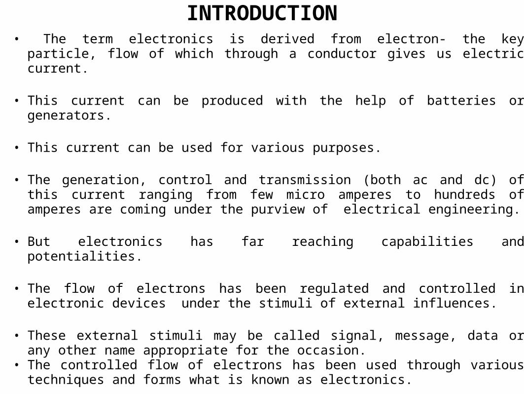
• The term electronics is derived from electron- the key particle, flow of which through a conductor gives us electric current.
• This current can be produced with the help of batteries or generators.
• This current can be used for various purposes.
• The generation, control and transmission (both ac and dc) of this current ranging from few micro amperes to hundreds of amperes are coming under the purview of electrical engineering.
• But electronics has far reaching capabilities and potentialities.
• The flow of electrons has been regulated and controlled in electronic devices under the stimuli of external influences.
• These external stimuli may be called signal, message, data or any other name appropriate for the occasion.
• The controlled flow of electrons has been used through various techniques and forms what is known as electronics.
INTRODUCTION

• APPLICATIONS OF ELECTRONICS
• The electronics plays an important role in almost every sphere of our life.
• It is very difficult to find anything starting from household goods, transports, health, communication, entertainment, multimedia, internets, where electronics has not made its presence felt.
• Besides the common electronic gadgets such as radio and TV receivers, audio and video tape recorder, frequency synthesizer, calculators, cameras, musical doorbells etc. electronics has offered its service in different walks of life.
• Some of the applications of electronics in various field are given below
• 1. Communications• The development of communication facilities is perhaps the most
significant gift of electronics in the twentieth century.• Besides bringing the people of the world closer through wireless
communication, in particular through internet, it has innumerable other applications

– Aircrafts make constant use of radio communication which provides information on the weather and terminal traffic.
– Satellites have revolutionized the field of communications– All the space voyages would not have been possible without electronics.
2. Applications in Digital Electronics.– Computer which revolutionized the world is one of the major achievements of
electronics.– Some of the other devices are electronic calculators, digital clocks etc.
3. Applications in Medical Science• In medical diagnostics and surgery, all scanning devices and
techniques use electronics in some form or the other.– Some of the machines/ equipment used by the doctors in diagnosis and
treatment are given below.– Electron microscope– X-rays– ECG. EEG, EMG, ENG,etc– Various scanning machines etc..
APPLICATIONS OF ELECTRONICS…
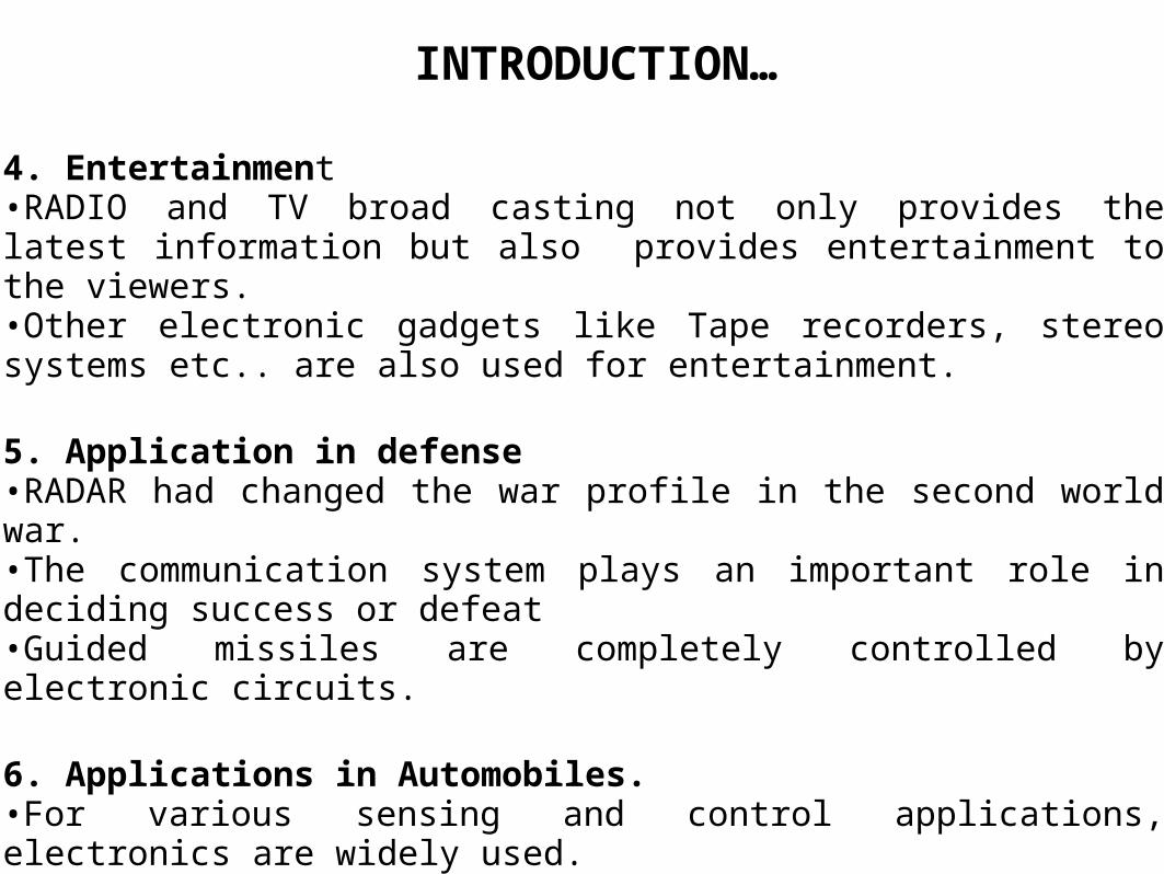
4. Entertainment•RADIO and TV broad casting not only provides the latest information but also provides entertainment to the viewers. •Other electronic gadgets like Tape recorders, stereo systems etc.. are also used for entertainment.
5. Application in defense•RADAR had changed the war profile in the second world war.•The communication system plays an important role in deciding success or defeat •Guided missiles are completely controlled by electronic circuits.
6. Applications in Automobiles.•For various sensing and control applications, electronics are widely used.
INTRODUCTION…
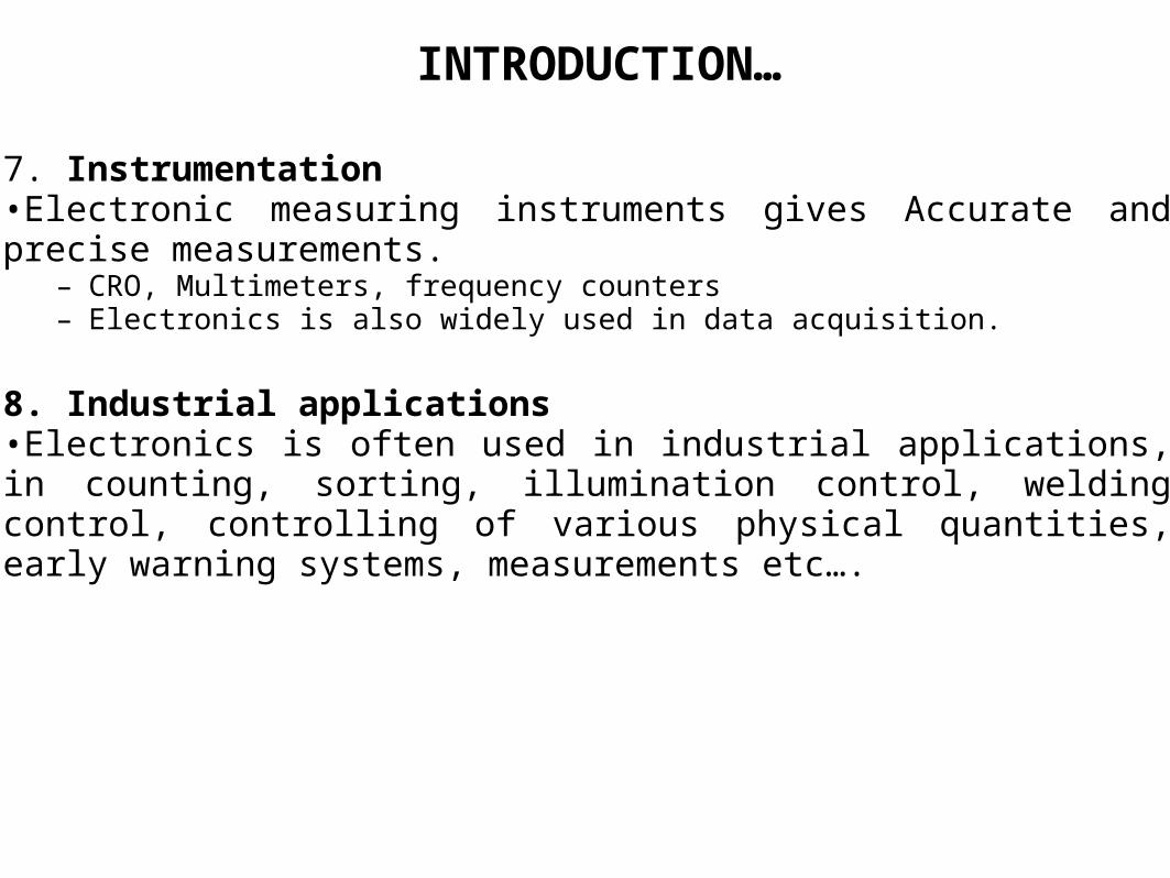
7. Instrumentation•Electronic measuring instruments gives Accurate and precise measurements.
– CRO, Multimeters, frequency counters – Electronics is also widely used in data acquisition.
8. Industrial applications•Electronics is often used in industrial applications, in counting, sorting, illumination control, welding control, controlling of various physical quantities, early warning systems, measurements etc….
INTRODUCTION…

Evolution of Electronics….• The age of electronics began with the birth of the vacuum diode of Sir
Ambrose Fleming in 1904.• In 1906 Lee De forest put a third electrode called grid, into the Flemings
valve and invented triode tube called audion. The audion was the first amplifier.
• 1912 First application of radio using diodes and triodes• First radio circuits from diodes triodes between 1907 and 1927• The superheterodyne receiver by Amstrong in 1920• Demonstration of television in 1925• 1930 Black and white TV introduced• FM modulation by Amstrong in 1933• RADAR in 1940
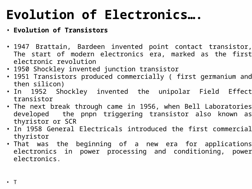
Evolution of Electronics….• Evolution of Transistors
• 1947 Brattain, Bardeen invented point contact transistor, The start of modern electronics era, marked as the first electronic revolution
• 1950 Shockley invented junction transistor• 1951 Transistors produced commercially ( first germanium and then silicon)• In 1952 Shockley invented the unipolar Field Effect transistor• The next break through came in 1956, when Bell Laboratories developed the
pnpn triggering transistor also known as thyristor or SCR• In 1958 General Electricals introduced the first commercial thyristor• That was the beginning of a new era for applications electronics in power
processing and conditioning, power electronics.
• T

Chap 1 - 9
The Start of the Modern Electronics Era
Bardeen, Shockley, and Brattain at Bell Labs - Brattain and Bardeen
invented the bipolar transistor in 1947.
The first germanium bipolar transistor. Roughly 50 years later,
electronics account for 10% (4 trillion dollars) of the world GDP.
Evolution of Electronics…
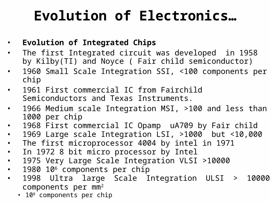
• Evolution of Integrated Chips• The first Integrated circuit was developed in 1958 by Kilby(TI) and Noyce
( Fair child semiconductor)• 1960 Small Scale Integration SSI, <100 components per chip• 1961 First commercial IC from Fairchild Semiconductors and Texas
Instruments. • 1966 Medium scale Integration MSI, >100 and less than 1000 per chip• 1968 First commercial IC Opamp uA709 by Fair child• 1969 Large scale Integration LSI, >1000 but <10,000• The first microprocessor 4004 by intel in 1971• In 1972 8 bit micro processor by Intel• 1975 Very Large Scale Integration VLSI >10000• 1980 106 components per chip• 1998 Ultra large Scale Integration ULSI > 10000 components per mm2
• 108 components per chip

Evolution of Electronics…
• Evolution of Computers • 1633 schiokherd in Germany invented mechanical computer.• 1833 First computing system analytical engine by Charles Babbage• 1933 Electro mechanical calculator – IBM, 17m long and 3 –m high• 1946 Electronic calculator introduced ( 18,000 vaccum tubes)• 1948 General purpose small electronic calculator• 1954 first generation computer (IBM 650 tube version)• 1959 Second generation computer ( IBM transistor version)• 1965 Third generation computer ( IBM IC version)• 1970 Computer with semiconductor memory• 1978 Entire computer on a single chip (6X6 mm2)• 1980 Micro computer general purpose digital processing and control
system.

Evolution of Electronic Devices
VacuumTubes
DiscreteTransistors
SSI and MSIIntegratedCircuits
VLSISurface-Mount
Circuits
Resistors
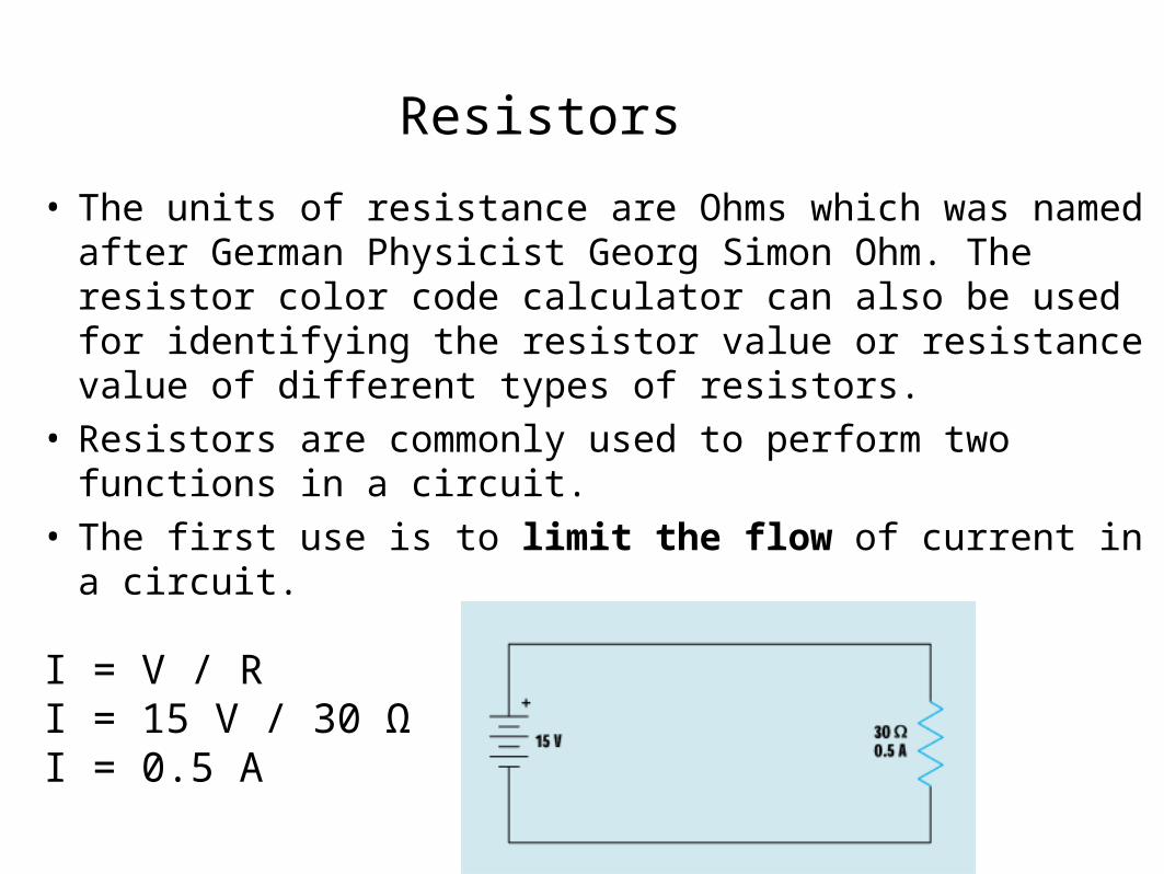
• The units of resistance are Ohms which was named after German Physicist Georg Simon Ohm. The resistor color code calculator can also be used for identifying the resistor value or resistance value of different types of resistors.
• Resistors are commonly used to perform two functions in a circuit.
• The first use is to limit the flow of current in a circuit.
I = V / RI = 15 V / 30 ΩI = 0.5 A

Resistors
• The second use is to produce a voltage divider.
A to B = 1.5 VA to C = 7.5 V A to D = 17.5 VB to C = 6 VB to D = 16 VC to D = 10 V

Resistors
Exceeding the power rating causes damage to a resistor.
Specifications.
Resistance is measured in units called ohms. The symbol for an ohm is Ω. Large values of resistance usually have prefixed. One thousand ohms is represented by one kilohm (kΩ) and one million ohms is the same as one megaohm (MΩ).
Resistors

Specifications. Tolerance
This always follows the value when describing a resistor
Definition: The maximum error in resistance value at room temperature
Units: Percent (%)
All processes have some degree of variation and there is a limit to how accurately resistance measurements can be made. This means the actual value may differ from the nominal value, and tolerance is a way of stating the limit on this.
In general, tighter tolerances (= lower % figures!) mean higher costs / prices. If the requested tolerance is unavailable, a tighter tolerance alternative can be used.
Specifications..
Thermal stability
TCR stands for Temperature Coefficient of Resistance
Definition: How much the resistance changes with temperature across a given temperature range
Units: Parts per million per degree C (ppm / °C) (1ppm = 0.0001% over a 100 °C change)
The resistive properties of all materials vary with temperature. Careful material selection and processing can minimize this.
This is generally more of an issue for precision resistors. These are often available in a range of TCR values - the lower the TCR, the higher the cost / price.

Specifications..
Power Rating
Any resistor functions such that it limits current flow while dropping voltage. It does this by changing some electrical energy into heat. The amount of energy the resistor is capable of safely changing into heat is called its power rating.
Definition: The maximum power which can be dissipated in the resistor at a certain ambient temperature is the resistor’s power rating.
Units: Watt (W) = 1 Joule / 1 second
If a resistor gets too hot it can a) change value, b) become unreliable or c) burn or damage the circuit board and surrounding product.
This sets a limit on how much electrical power can be allowed to turn into thermal energy in a given time.
The power rating relates to continuous dissipation for an indefinite time. Resistors can dissipate more power if the time is limited to a fraction of a second or a few seconds, known as pulse power.

Types of Resistors
• Resistors are basically of two types namely linear and non-linear resistors.
• Each type is further subdivided into many types as shown in figure.
• 1. Linear Resistors
• The resistors through which the current is directly proportional to the applied voltage, are called linear resistors.
• The resistance value do not change with the variation in applied voltage , temperature or light intensity.
• Linear resistors are of two types• Fixed resistors
• Variable resistors

• FIXED RESISTORS
– Fixed resistors have only one ohmic value, which cannot be changed or adjusted.
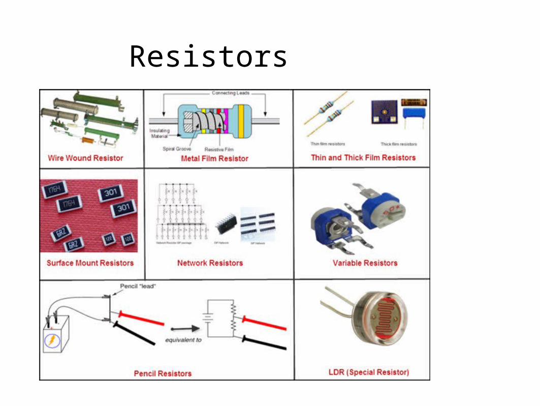
– Fixed resistors are of the following types– i) Carbon composition resistors– ii) Thin film resistors– iii)Thick film resistors– iv) Wire-wound resistors
Types of Resistors

i) CARBON COMPOSITION RESISTORS
• Carbon composition resistors are made by mixing carbon powder and insulating binders to produce desired resistance
• Usually the resistance element is a simple rod of carbon powder which is enclosed in plastic case
• The two ends of the carbon resistance element are joined to metal caps with leads of tinned wire.
• Available in resistance values ranging from 1Ω to 22MΩ• Power rating varies from 1/8,1/4,1/3,1/2,2/3,1and 2
watts.• The size of these resistors vary with power rating.
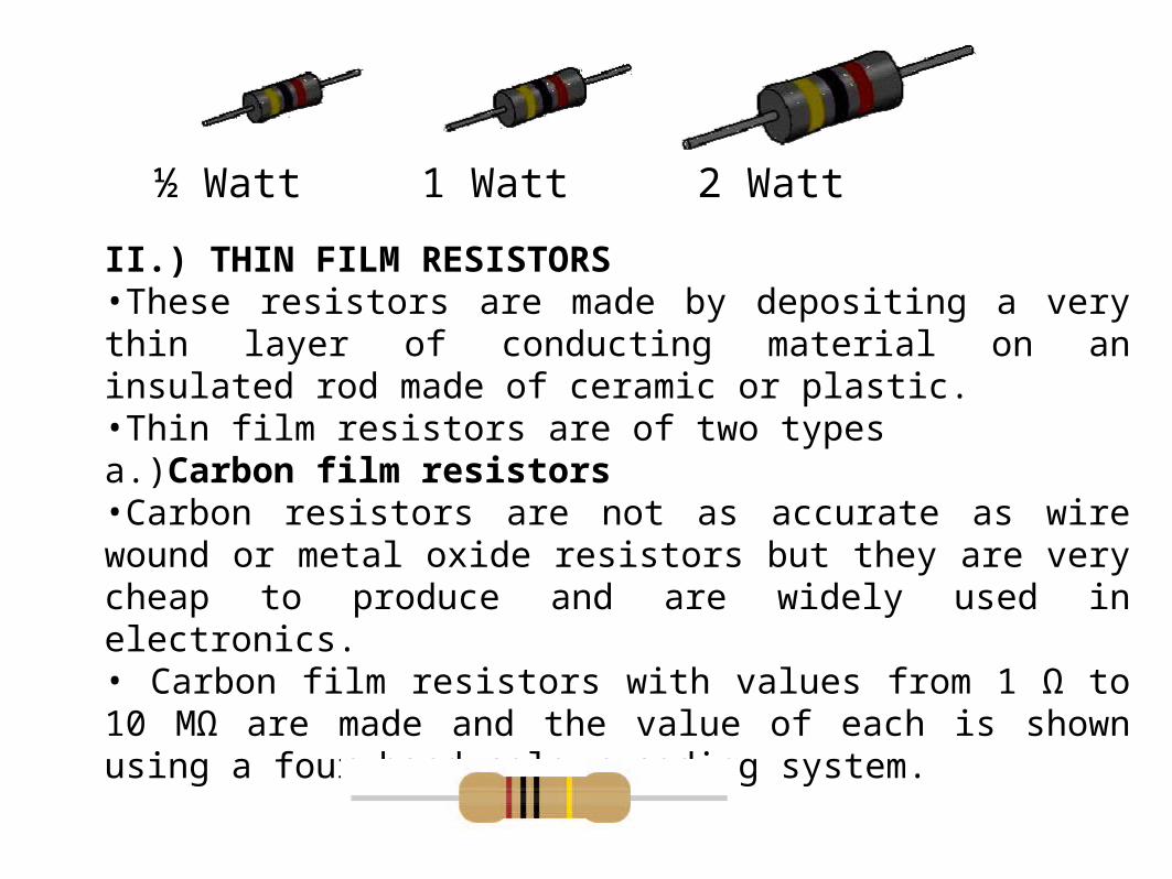
II.) THIN FILM RESISTORS•These resistors are made by depositing a very thin layer of conducting material on an insulated rod made of ceramic or plastic. •Thin film resistors are of two typesa.)Carbon film resistors •Carbon resistors are not as accurate as wire wound or metal oxide resistors but they are very cheap to produce and are widely used in electronics.• Carbon film resistors with values from 1 Ω to 10 MΩ are made and the value of each is shown using a four band colour coding system.
½ Watt 1 Watt 2 Watt
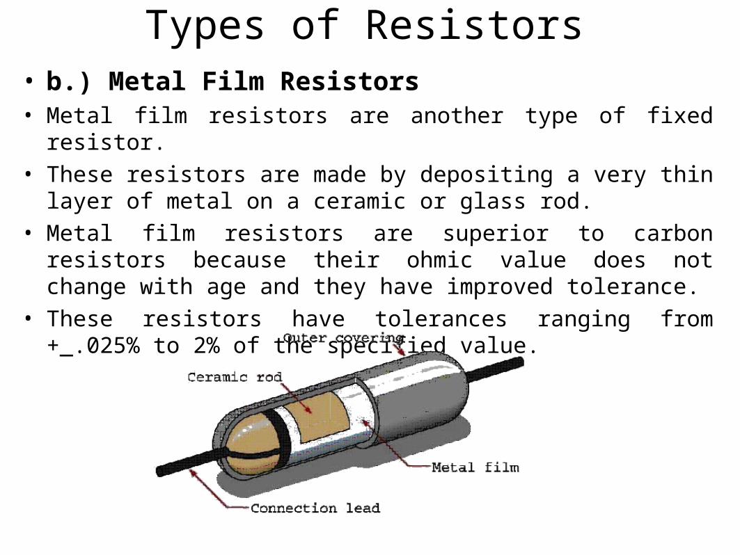
• b.) Metal Film Resistors• Metal film resistors are another type of fixed resistor.
• These resistors are made by depositing a very thin layer of metal on a ceramic or glass rod.
• Metal film resistors are superior to carbon resistors because their ohmic value does not change with age and they have improved tolerance.
• These resistors have tolerances ranging from +_.025% to 2% of the specified value.
Types of Resistors
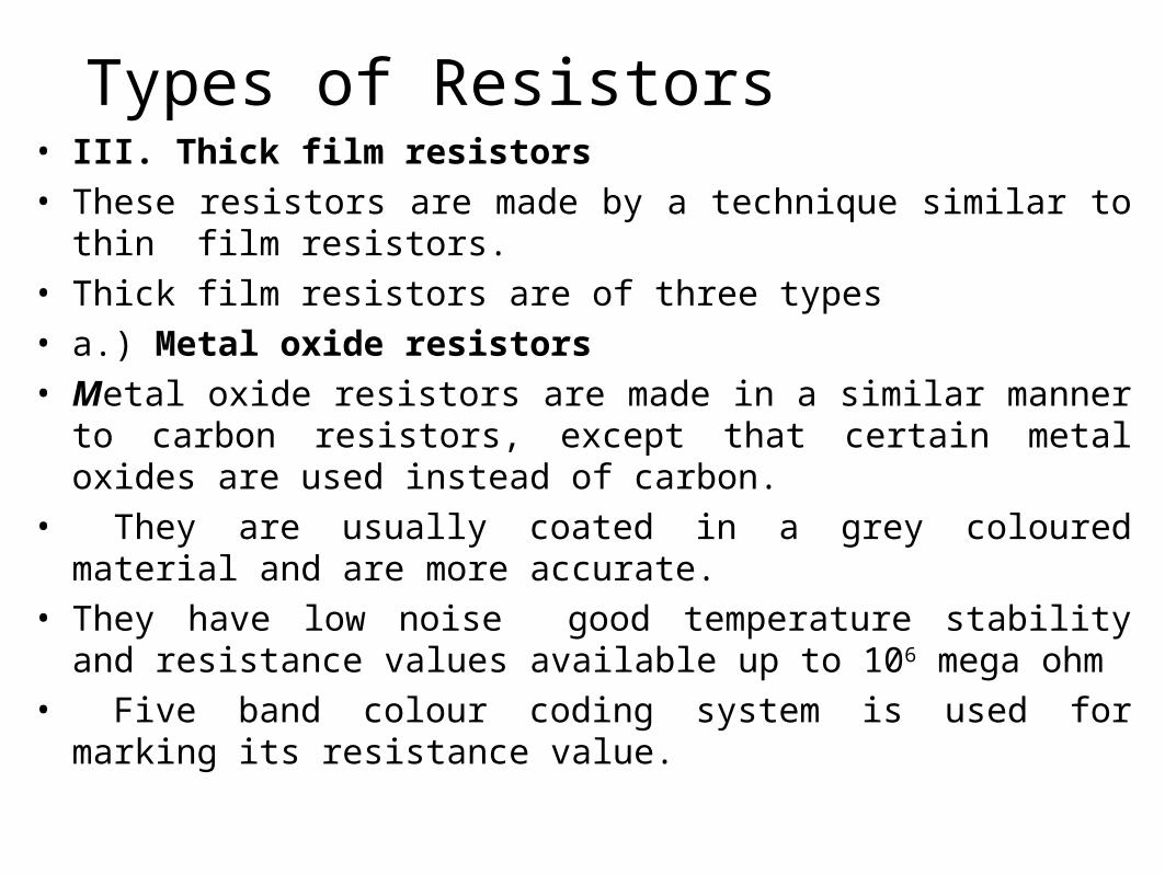
Types of Resistors • III. Thick film resistors• These resistors are made by a technique similar to thin film
resistors. • Thick film resistors are of three types• a.) Metal oxide resistors• Metal oxide resistors are made in a similar manner to carbon
resistors, except that certain metal oxides are used instead of carbon.
• They are usually coated in a grey coloured material and are more accurate.
• They have low noise good temperature stability and resistance values available up to 106 mega ohm
• Five band colour coding system is used for marking its resistance value.
Resistors
• B.)Bulk property film resistor• These are made of metal film which is photo etched to provide
close resistance tolerance values ranging from ±0.1% to 1%• These resistors have low noise, very low temperature
coefficient and can work at high frequency.• C.) Cermet film resistor• These are made by placing a coating of metal alloy along with
insulating material on a ceramic substrate. The combination is then fired into a ceramic metal called cermet.
• They provides the highest resistance values than any other resistive material.
• Resistance value can be up to up to 500Mohm and tolerances ranging from ±0.5% to 2 %
Types of Resistors…

TYPES OF RESISTORS…
IV. Wire-wound resistors
•Wire-wound resistors are fixed resistors that are made by winding a piece of resistive wire (nichrome) around a ceramic core. •The wire is then coated with an insulating material•The wire is connected to the two resistor leads and coated with an insulating plastic. •These are used when a high power rating is required.
• In this type of resistor, the value is usually written on the protective coating. •Wire wound resistors are used when extremely accurate and high wattage values are needed.

• The resistance values of Variable resistors can be varied from 0 to a specified value.
• It is used in electronic circuits to adjusts values of current and voltage.
• They find applications in changing the volume of sound, brightness of a television picture etc..
• Variable resistors are of the following three type.
• Wire wound variable resistor
• Potentiometer and
• Trimmer or preset
VARIABLE RESISTORS

• a.)Wire wound variable resistor• These resistors are made of nichrome wire wound on a
ceramic core and covered with an insulative coating, a window is left on the insulating cover.
• An adjustable tap is rides along the exposed wire . This act as the adjustable point.
• These are used in power supplies and low frequency circuits.
• It is not suitable for high frequency application
• Wire wound resistor are available with resistance values ranging from 1Ω to 150 K Ω with ±5% to ±10% tolerance and power rating from 3 watts to 200w
VARIABLE RESISTORS…

TYPES OF RESISTORS…
• b.) Potentiometers• The name potentiometer comes from the use of this device as
potential meter.• Potentiometers usually have three connecting points.• Two are connected to the ends of the resistance material and the third
is connected to the central sliding contact. • the outer terminal are fixed and the middle terminal is variable.
• The slider can either slide in a straight line or around a curve. This is shown in Figure.

• Thin resistance wire, or a strip of carbon material, is used in potentiometers where circuit current are small
• However, in potentiometers where large currents are flowing , such as in those used for light dimmers, very thick resistance wire is used.
TYPES OF RESISTORS…
c.) Trimmers (Preset resistors)
•These are used in electronic circuits to trim the circuit to the desired operating conditions.•The materiail used in the construction of trimmers are carbon composition, carbon film,cermet and wire. •Resistance values ranging from 50Ω to 5M Ω with a power rating of ¼ watt to ¾ watt•preset resistors operate on the same principle as potentiometers except the value is usually adjusted when a circuit is being tested and then left on that setting.• They are usually adjusted by using a small screwdriver.
TYPES OF RESISTORS…

NON –LINEAR RESISTORS
• These resistors are made from semiconducting materials.
• The non linear property of the resistors arises due to the breaking of covalent bonds in the semiconducting material.
• The source of energy for the creation of charge carriers in semiconducting materials may be voltage, temperature or incident light
• The non-linear resistors are of three types
• 1. Thermistors 2. Photo resistors 3. Varistors.

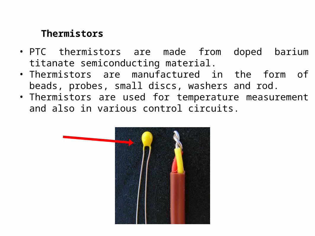
Thermistors•The word thermistor is an acronym for thermal resistor. ie; temperature sensitive resistors, the resistance varies with temperature.•The variation in temperature is reflected through an appreciable variation of the resistance of the device.•Hence It is able to detect even small changes in temperature. •Thermistors with both negative – temperature coefficient (NTC) and positive temperature coefficient (PTC) are available.• NTC means that the resistance decreases with increase in temperature, these are commonly used.•PTC means that the resistance increases with increase in temperature.
•The NTC thermistors are manufactured by sintering semiconductor ceramic materials prepared from mixtures of metallic oxides of cobalt, nickel, manganese etc.•These materials have high negative temperature coefficient of resistance
Thermistors
• PTC thermistors are made from doped barium titanate semiconducting material.
• Thermistors are manufactured in the form of beads, probes, small discs, washers and rod.
• Thermistors are used for temperature measurement and also in various control circuits.
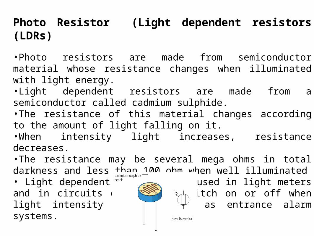
Photo Resistor (Light dependent resistors (LDRs)
•Photo resistors are made from semiconductor material whose resistance changes when illuminated with light energy.•Light dependent resistors are made from a semiconductor called cadmium sulphide.•The resistance of this material changes according to the amount of light falling on it.•When intensity light increases, resistance decreases.•The resistance may be several mega ohms in total darkness and less than 100 ohm when well illuminated• Light dependent resistors are used in light meters and in circuits designed to switch on or off when light intensity changes, such as entrance alarm systems.

Varistor ( Voltage Dependent Resistor)
•The word Varistor is an acronym for variable resistor•These are used to protect circuits from high voltage transients and surges.•When a transient occurs, the varistor resistance changes from a very high stand-by value to a very low conducting value.
•The transient is thus absorbed and clamped to a safe level, protecting sensitive circuit components.

Resistor Color Code
• As the carbon film and carbon composition resistors are very small in size to print the value of resistance, color bands are printed to calculate the resistor value.
• The resistor color code consists of different bands on the resistor with different colors (colors from resistor color code chart).

Resistor Color Code Chart•The resistor color code chart is shown in the figure•This consists of different colors, significant figures, multiplier values, tolerance values, and temperature coefficients that are used in resistor colour code calculator.
Color ValueBlack 0Brown 1Red 2Orange 3Yellow 4Green 5Blue 6Violet 7Gray 8White 9

Representation of Resistor Bands Where,
• Band 1 represents the first significant number of resistor values
• Band 2 represents the second significant number • Band 3 represents the third significant number can be
observed in five band resistors and six band resistors • Band 4 represents multiplier value (decimal) • Band 5 represents the percentage of tolerance value • Band 6 represents temperature coefficient value
Resistor Color Code…

• The resistor color code can be used to determine the resistor’s ohmic value and tolerance. 1500ohm with 10% tolerance
Resistor Color Code…

Resistor Color Coding

a. )Two digits plus multiplier
AB*10C
Yellow – Violet – Red47*102
4700 Ω ±20%
c.) Brown – Black-Black – Red - Silver100*102
10000 Ω ±10%. 10K Ω ±10%.
Tolerance
Gold +/-5%Silver +/-10%None +/-20%
b )Two digits plus multiplier and tolerance
Yellow – Violet – Red-Gold47*102
4700 Ω ±5%
Resistor Color Coding…

4-Band Resistor
5-Band Resistor 6-Band Resistor
State the colours of the bands for each of the following resistors.a. 18 Ω 5% carbon filmb. 270 Ω 10% carbon filmc. 8.2 kΩ 10% carbon filmd. 8.20 kΩ 1% metal oxidee. 470 kΩ 1% metal oxide

Resistors
Schematic symbols are used to represent various types of fixed resistors.

Standard Values Resistors
10 3311 3612 3913 4315 4716 5118 5620 6222 6824 7527 8230 91
10 3312 3915 4718 5622 6827 82
Available in +/-5%
Available in +/-10%
Range of values is from 0.10 ΩTo 22.0 x10⁶ Ω
Resistors
Review:
1. Resistors are used in two main applications: as voltage dividers and to limit the flow of current in a circuit.
2. The value of fixed resistors cannot be changed.3. There are several types of fixed resistors such as
composition carbon, metal film, and wire-wound.
4. Carbon resistors change their resistance with age or if overheated.
5. Metal film resistors never change their value, but are more expensive than carbon resistors.
6. The advantage of wire-wound resistors is their high power ratings.
Unit 5 Resistors
Review:
7. Resistors often have bands of color to indicate their resistance value and tolerance.
8. Resistors are produced in standard values. The number of values between 0 and 100 Ω is determined by the tolerance.
9. Variable resistors can change their value within the limit of their full value.
10. A potentiometer is a variable resistor used as a voltage divider.

Commonly used metric prefixes and their symbols
PREFIX+ UNIT METRIC SYMBOL MULTIPLIER LETTER
Teraohms T 1012 TGigohms G 109 GMegohms M 1,000,000 MKilohms k 1000 KOhms 1 RMilliohms m 0.001 R
1.5 is written 1.50.01 is written .01 10,500 (10.5k) is written 10.5K1,800,000 (1.8M) is written 1.8M0.005 (5m) is written .005 (for some manufacturers is written or marked as R005)