whole arm planning for a soft and highly compliant 2d...
TRANSCRIPT
Whole Arm Planning for a Soft and Highly Compliant 2D RoboticManipulator
Andrew D. Marchese, Robert K. Katzschmann, and Daniela Rus
Abstract— Soft continuum manipulators have the advantageof being more compliant and having more degrees of freedomthan rigid redundant manipulators. This attribute should allowsoft manipulators to autonomously execute highly dexteroustasks. However, current approaches to motion planning, inversekinematics, and even design limit the capacity of soft manipu-lators to take full advantage of their inherent compliance. Weprovide a computational approach to whole arm planning fora soft planar manipulator that advances the arm’s end effectorpose in task space while simultaneously considering the arm’sentire envelope in proximity to a confined environment. Thealgorithm solves a series of constrained optimization problemsto determine locally optimal inverse kinematics. Due to inherentlimitations in modeling the kinematics of a highly compliantsoft robot and the local optimality of the planner’s solutions,we also rely on the increased softness of our newly designed ma-nipulator to accomplish the whole arm task, namely the arm’sability to harmlessly collide with the environment. We detail thedesign and fabrication of the new modular manipulator as wellas the planner’s central algorithm. We experimentally validateour approach by showing that the robotic system is capableof autonomously advancing the soft arm through a pipe-likeenvironment in order to reach distinct goal states.
I. INTRODUCTION
Soft robots are predominantly made of soft materials andhave a continuously deformable structure, providing a rela-tively large number of degrees of freedom when comparedto their hard counterparts, as reviewed by Trivedi, Rahn,Kier, and Walker [1]. Furthermore, soft robots are oftencharacterized by distributed actuation and are fundamentallyunderactuated, that is they have many passive degrees offreedom. As a soft robot’s body becomes more compliant,its dexterity increases and this is a major advantage overtraditional hard bodied robots. For example, such a dexterousrobot can access confined areas and execute economicallydifficult tasks. However, to actually get this benefit from softrobots, we need both computational advances in kinematicsand control, as well as advanced designs and fabricationtechniques for soft manipulators. Traditional approaches tokinematics and control for soft robots do often not considerthe robot’s entire shape or envelope, preventing autonomousnavigation in confined environments.
In this work, we provide an approach for autonomouslymoving a soft and highly compliant planar robot arm througha confined environment. We provide a computational ap-proach to whole arm planning that finds a solution to the in-verse kinematics problem for this class of arms. The solution
Andrew D. Marchese, Robert K. Katzschmann, and Daniela Rus are withthe Computer Science and Artificial Intelligence Laboratory, MassachusettsInstitute of Technology, 32 Vassar St. Cambridge, MA 02139, USA,{andy, rkk, rus}@csail.mit.edu
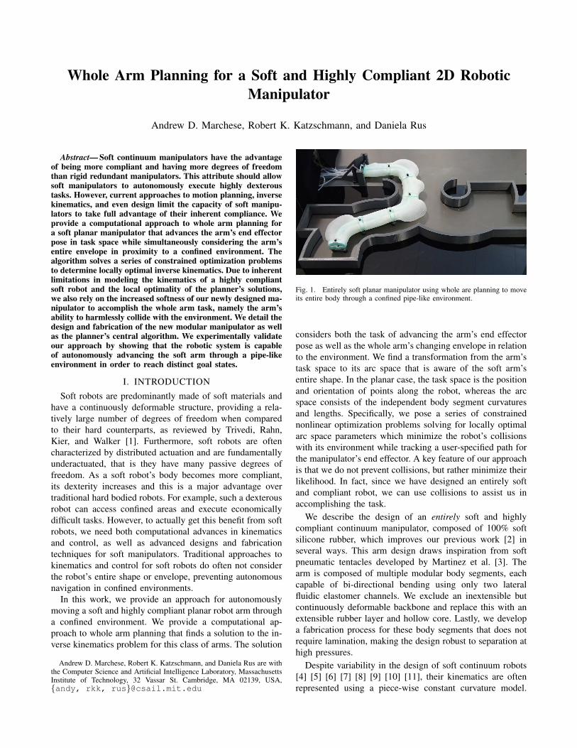
Fig. 1. Entirely soft planar manipulator using whole are planning to moveits entire body through a confined pipe-like environment.
considers both the task of advancing the arm’s end effectorpose as well as the whole arm’s changing envelope in relationto the environment. We find a transformation from the arm’stask space to its arc space that is aware of the soft arm’sentire shape. In the planar case, the task space is the positionand orientation of points along the robot, whereas the arcspace consists of the independent body segment curvaturesand lengths. Specifically, we pose a series of constrainednonlinear optimization problems solving for locally optimalarc space parameters which minimize the robot’s collisionswith its environment while tracking a user-specified path forthe manipulator’s end effector. A key feature of our approachis that we do not prevent collisions, but rather minimize theirlikelihood. In fact, since we have designed an entirely softand compliant robot, we can use collisions to assist us inaccomplishing the task.
We describe the design of an entirely soft and highlycompliant continuum manipulator, composed of 100% softsilicone rubber, which improves our previous work [2] inseveral ways. This arm design draws inspiration from softpneumatic tentacles developed by Martinez et al. [3]. Thearm is composed of multiple modular body segments, eachcapable of bi-directional bending using only two lateralfluidic elastomer channels. We exclude an inextensible butcontinuously deformable backbone and replace this with anextensible rubber layer and hollow core. Lastly, we developa fabrication process for these body segments that does notrequire lamination, making the design robust to separation athigh pressures.
Despite variability in the design of soft continuum robots[4] [5] [6] [7] [8] [9] [10] [11], their kinematics are oftenrepresented using a piece-wise constant curvature model.
The piece-wise constant curvature assumption means eachbody segment of a multi-segment arm is assumed to deformwith constant curvature. This representation for continuumrobots is reviewed by Webster and Jones [12]. Hannan andWalker [13] provide an early example of the piecewiseconstant curvature model. As Webster’s review discusses, thegenerality of this modeling assumption is due to the physicsbehind the deformation. Specifically, Gravagne, Rahn, andWalker [14] and Li and Rahn [15] show a moment appliedby a guided cable fixed to the end of a continuum backboneproduces constant curvature along the backbone. Jones andWalker [16] show that the constant curvature concept alsoapplies to pneumatic muscle actuators bending a continuumbackbone. Recently, Onal, Chen, Whitesides, and Rus showrectangular fluidic elastomer actuators with uniform channelsdeform along an arc of constant curvature [17]. Marchese,Komorowski, Onal and Rus [2] demonstrate autonomousclosed-loop positioning of a soft and highly compliant inex-tensible planar arm under the piecewise constant curvaturemodeling assumption. Both the forward kinematics and theclosed-loop curvature controller of that work are reused forthe new extensible soft planar arm presented in this paper.
A limitation of existing approaches to solving the inversekinematics problem for soft continuum arms is that currentlythe whole arm, in addition to the end effector’s pose, is notconsidered in the solution. Autonomous obstacle avoidanceand movement through a confined environment is difficultwithout a computational solution to the inverse kinematicsproblem that is aware of the robot’s whole arm in space.Buckingham [18] articulates as a distinguishing advantage ofa snake-like arm, that it can potentially achieve the primarytask of tip control, while meeting the secondary task of shap-ing the whole arm. Neppalli, Csencsits, Jones, and Walker[19] provide a closed-form IK solution for continuum arms,but the Jacobian-based solution only considers the endpointof the final body segment and obstacle avoidance requiresmanual planning. Jones and Walker [20] control Air-OCTORand OctArm using fast real-time Jacobian control over task-space, but rely on joystick control for whole arm taskslike manipulation and grasping [21]. Local optimization hasshown promising results for rigid-bodied redundant manipu-lators [22], but as far as we are aware such a technique hasnot been used to solve the whole body manipulation problemfor a soft robot. Furthermore, we are not aware of anyexisting soft-bodied fluidic robots with highly deformableexterior envelopes [23] [17] [24] [25] [2] [26] [27] [3] thatconsider whole body manipulation when moving in task-space. With fewer kinematic constraints, the envelop of thesesoft robots expand or radially bulge at locations along thebody under actuation. Accordingly, whole body planning forsoft and highly compliant robots must take into considerationthis dynamic envelope.
The main contributions of this paper to soft-bodiedrobotics are:
• A planner for whole body motion of a soft planarmanipulator that considers the tasks of both controllingend effector pose while minimizing collisions between
the whole arm’s changing envelop and a confiningenvironment.
• A modular design for a pneumatic highly compliantplanar manipulator that is composed entirely of softsilicone rubber, which improves on [2].
II. DESIGN
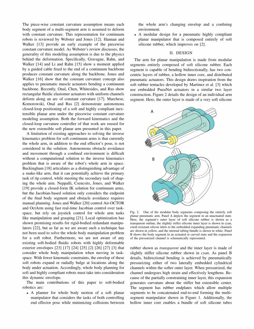
The arm for planar manipulation is made from modularsegments entirely composed of soft silicone rubber. Eachsegment is capable of bending bidirectionally, has two con-centric layers of rubber, a hollow inner core, and distributedpneumatic actuators. This design draws inspiration from thesoft rubber tentacles developed by Martinez et al. [3] whichuse embedded PneuNet actuators in a similar two layerconstruction. Figure 2 details the design of an individual armsegment. Here, the outer layer is made of a very soft silicone
B
A
Fig. 2. One of the modular body segments composing the entirely softplanar pneumatic arm. Panel A depicts the segment in an unactuated state.Here, the segment’s outer layer of soft silicone rubber is shown as atransparent outline, the slightly stiffer silicone inner layer is shown in cyan,crush resistant silicon inlets to the embedded expanding pneumatic channelsare shown in yellow, and the internal tubing bundle is shown in white. PanelB shows the body segment in an actuated or curved state and the expansionof the pressurized channel is schematically represented.
rubber shown as transparent and the inner layer is made ofslightly stiffer silicone rubber shown in cyan. As panel Bdetails, bidirectional bending is achieved by pneumaticallypressurizing either of two laterally embedded cylindricalchannels within the softer outer layer. When pressurized, thechannel undergoes high strain and effectively lengthens. Be-cause of the partially constraining inner layer, this expansiongenerates curvature about the stiffer but extensible center.The segment has rubber endplates which allow multiplesegments to be concatenated end-to-end forming the multi-segment manipulator shown in Figure 1. Additionally, thehollow inner core enables a bundle of soft silicone tubes

shown in white to pass through each segment. On one end,each tube individually connects to each actuated channelin the multi-segment arm by means of a crush resistantsilicone insert shown in yellow. On the other end, each tubeconnects to the outlet of a fluidic drive cylinder detailed in[2]. These cylinders allow each channel to be individuallypressurized. The relationship between neutral axis curvature,internal channel pressure, and delivered volume for a singlearm segment is characterized in Figure 3. In this experimentalcharacterization, one of the segment’s two channels wasincrementally filled under volume control and both internalchannel pressure and curvature were derived from measure-ments at each fill increment. Curvature is assumed to beconstant along the length of the segment and is uniquelydefined by measuring the starting pose and end point of thesegment.
0 10 20 30 40 50 600
5
10
15
20
25
Cur
vatu
re [m
−1 ]
0 10 20 30 40 50 600
10
20
30
40
50
Pre
ssur
e [k
Pa]
Volume [mL]
Fig. 3. Experimental characterization of a single soft arm segment. Volumeis incrementally delivered to one of the segment’s embedded channels andboth the resulting internal pressure and segment curvature are derived frommeasurements.
This design is an extension of the planar manipulator pre-sented in [2] in that we change both its kinematic constraintsand distributed actuators. We remove the inextensible con-straining backbone layer and replace this with an extensible,but partially constraining silicone layer. Also, we move awayfrom the multiple vertical channels characterizing fluidicelastomer actuators [23] and adopt two lateral cylindrically-shaped channels. The primary benefits of this new designcompared to the previous design are that (1) its entirely softconstruction, concentric layers, and hollow core make thisarm simpler to fabricate, (2) the modular design enablesscalability in the number of body segments, and (3) theactuators do not have the problem of delaminating underhigh pressures, because the embedded channels are not atthe interface between layers.
III. FABRICATION
In the following section we describe the fabrication pro-cess for this robot as well as the tools and equipment used,which are listed in Table I. We fabricate the arm through acasting process that uses pourable silicone rubber2,4 and 3Dprinted molds1.
Figure 4 details this process. First, each body segmentis independently fabricated in steps 1-3 and later thesesegments are joined serially to form the arm in steps 4 and 5.To start, a four piece mold was printed. The mold is pouredin two steps. In step 1, a low elastic modulus rubber2 ismixed, degassed in a vacuum3, and poured to form the bodysegment’s soft outer layer shown in white. The mold’s outerpiece, one half of it is shown in green, functions to form thesegment’s exterior. Metal rods shown in pink are insertedinto the mold and are held in place by the orange bottompiece of the mold. These rods will form the cavities for thesegment’s two lateral pneumatic actuation channels.
After the outer layer has cured, the red rigid sleeve isremoved in step 2 from the extruded feature of the orangebottom piece of the mold. This produces a cavity intowhich the slightly stiffer rubber4 is poured, forming thesegment’s partially constraining inner layer shown in cyan.The extruded feature of the orange bottom piece, shown byits orange end tip, functions to produce the segment’s hollowinterior core.
In step 3, the body segments are removed from their moldsand joined to soft rubber4 endplates shown in cyan usingadhesive5. The small yellow channel inlets were added onone side of the pink metal pins during step 1.
In step 4, soft silicone tubes6 are joined to each embeddedchannel’s inlet. The resulting bundle of tubes is passedthrough each segment’s hollow interior. Lastly, in step 5multiple body segments are attached at their endplates usingthe same adhesive5.
1 2
3 4 5
For (each segment)
1. Cast soft outer shell (white)
2. Cast adjoint stiffer inner
constraint
3. De-mold and join
with soft end plates
4. Add tubes to all inlets and
pass them through
5. Combine segments
Fig. 4. Each body segment is cast using a two step process where the outersoft layer (1) and inner stiffer layer (2) are poured. Once cured, the segmentsare joined to endplates using silicone adhesive (3). Next, silicone tubing isconnected to each embedded channel and the resulting tubing bundle is runinside each segment’s hollow interior (4). Lastly, the body segments areserially connected using adhesive to form the manipulator (5).
IV. CONTROL
The key operation for controlling the arm is closed-loopcurvature control. By controlling the curvatures of the armsegments, we can achieve forward and inverse kinematicsas shown in [2]. Here we extend on this work to derivea planning system for planar soft arms. The planning and
TABLE ICOMMERCIALLY AVAILABLE TOOLS AND EQUIPMENT
1 Fortus 400mc, Stratasys Ltd., Eden Prairie, MN2 Ecoflex 0030, Smooth-On, Easton, PA3 AL Cube, Abbess Instruments and Systems, Inc., Holliston, MA4 Mold Star 15, Smooth-On, Easton, PA5 Silicone Sealant 732, Dow Corning Corp, Midland, MI6 PN 51845K52, McMaster, Princeton, NJ
inverse kinematics problems are solved simultaneously usingconstrained nonlinear optimization as opposed to an iterativejacobian approach.
A. Kinematics
The orientation of any point s ∈ [0, Li] along the arc rep-resenting segment i within n arm segments can be expressedas:
θi(s) = kis+ θi(0) (1)
where ki is the given curvature of element i. The serialconnection of the segments leads to θi(0) = θi−1(Li−1).The forward kinematics at arc length s on segment i alongthe arm’s central axis can therefore be expressed as:
xi(s) = xi−1(Li−1) +
∫ s
0
cos (θi(s′)) ds′, (2)
yi(s) = yi−1(Li−1) +
∫ s
0
sin (θi(s′)) ds′. (3)
whereas xi(s) and yi(s) are cartesian coordinates, and Li isthe given length of segment i.
B. Curvature Control
The control of the new arm design is achieved by theuse of the previously developed system for closed-loopcurvature control of each segment [2]. In short, this closed-loop curvature controller periodically receives discrepanciesbetween the soft arm’s measured and requested curvatures kiand uses a two-staged cascaded control approach to adjustthe fluidic drive cylinders and resolve the error. An externaltracking system (Opti Track, NaturalPoint Inc., Corvallis,OR) detects markers positioned at the end of each armsegment and calculates the measured curvatures of eachsegment using the arm’s inverse kinematics. The measuredcurvatures minus the reference curvatures result in errors,which are passed on to PI controllers also running at 20 Hz.The outputs of the PI controllers are used as set points forthe embedded PID controllers of the linear actuators. Thesecontrollers run at 1 kHz and ensure that the actuated cylinderpistons provide the appropriate volumetric displacement inorder to attain the desired curvatures.
C. Whole Arm Planner
We are controlling the shape of a soft planar multi-segmentcontinuum arm to move into a bounded environment. We rep-resent the arm using a piecewise constant curvature model.That is, each of the arm’s n body segments have length liand are assumed to deform in an arc of constant curvature
κi, where i = 1 . . . n. The task space of the arm consists ofthe position and orientation of a point w = [x, y, θ] alongthe arm. The goal of this algorithm is to find a local optimumfor the transformation from the arm’s task space to the arm’sconfiguration space [12] described by curvature values whileconsidering the robot’s envelope points h ∈ H ⊆ R2 inrelation to its environment points e ∈ E ⊆ R2. The envelopeH is modeled by trapezoids scaled linearly according to themeasured curvature value. The environment E is representedas a set of points and is known a priori. We assume that thearm is initially always placed in a free space outside thebounded environment we want to enter. Also, a series oftask space waypoints is predefined by the user, where thefirst waypoint is placed at the inlet to the environment. Allfollowing waypoints describe a path that would lead to afinal goal position inside the environment.
The optimization approach to solve for whole arm controlis laid out in Algorithm 1, visually supported by Figure 5and explained in further detail in the following. At the starttime t = 1, we set the arm segments to a locally optimalκ, that places the tip according to the forward kinematicsFORWKIN(κ, l) at the first waypoint w1 while ensuring thatthe extreme curvatures κmin and κmax are not exceeded.The extreme curvatures are experimentally determined to beeither the maximum curvatures achievable given the fixedvolumetric displacements of the fluidic drive cylinders orcurvatures which damage the segments due to over inflation.
After the start, we enter a loop until the last waypointat time step N is reached. At the start of the loop, wefind the closest environment points left e1,t and right e1,tof the arm’s body shape. To define the two sides of thearm, we use the arm’s approach vector nt and the angleα = ∠(e−wt,nt). The origin of the end-effector’s approachvector nt is defined by the positions x and y and its directionby the angle θ. Positive values for α result in the closest pointe1,t left of wt and negative values result in e2,t to the rightof wt. Next, we calculate the arm hulls ARMHULL(κt, L)of both sides by modeling each segments bulging side witha trapezoid that is linearly scaled in height by the curvaturevalue. The concave side is not vacuumed during the actuationprocess, so the hull is described by a constant offset fromthe curved body centerline. For every stored environmentpoint ei,j , i = 1 . . . 2 and j = 1 . . . t, we find the closesthull points, calculate their connection vector and calculatethe normals of the environment ENVNORMAL(ei,j) at eachstored environment point. We then perform an optimizationto find the curvatures that best fit the hull into the environ-ment while achieving the current target waypoint. Finally,the time step is incremented and the loop repeats until thelast waypoint is calculated.
D. Implementation
The optimization algorithm was implemented using Mat-lab’s Optimization Toolbox with the function calls fmincon,which finds the minimum of a constrained nonlinear mul-tivariable function. Sequential Quadratic Programming wasused as the solver with a relative upper bound of 2× 10⁻³
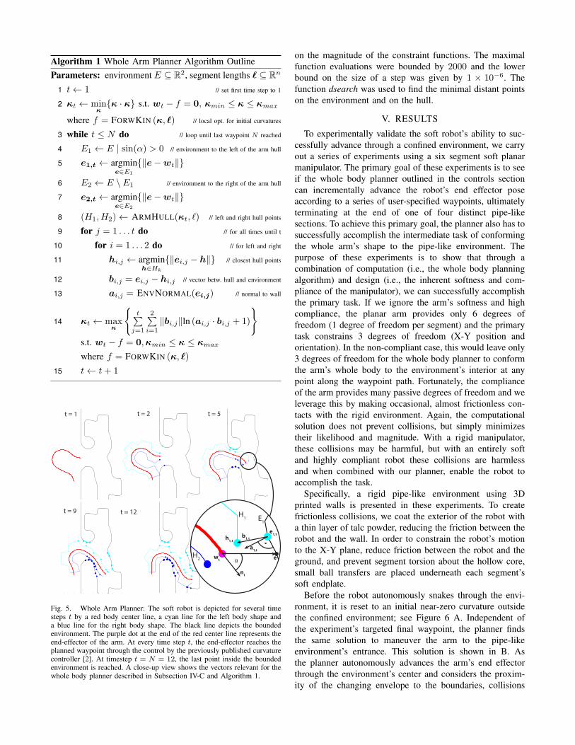
Algorithm 1 Whole Arm Planner Algorithm OutlineParameters: environment E ⊆ R2, segment lengths ℓ ⊆ Rn
1 t← 1 // set first time step to 1
2 κt ← minκ{κ · κ} s.t. wt − f = 0, κmin ≤ κ ≤ κmax
where f = FORWKIN (κ, ℓ) // local opt. for initial curvatures
3 while t ≤ N do // loop until last waypoint N reached
4 E1 ← E | sin(α) > 0 // environment to the left of the arm hull
5 e1,t ← argmine∈E1
{∥e−wt∥}
6 E2 ← E \ E1 // environment to the right of the arm hull
7 e2,t ← argmine∈E2
{∥e−wt∥}
8 (H1,H2)← ARMHULL(κt, ℓ) // left and right hull points
9 for j = 1 . . . t do // for all times until t
10 for i = 1 . . . 2 do // for left and right
11 hi,j ← argminh∈Hk
{∥ei,j − h∥} // closest hull points
12 bi,j = ei,j − hi,j // vector betw. hull and environment
13 ai,j = ENVNORMAL(ei,j) // normal to wall
14 κt ← maxκ
{t∑
j=1
2∑i=1
∥bi,j∥ln (ai,j · bi,j + 1)
}s.t. wt − f = 0,κmin ≤ κ ≤ κmax
where f = FORWKIN (κ, ℓ)
15 t← t+ 1
b1,t
a1,t
e1,t
E1
H1
wt
t = 1 t = 2 t = 5
t = 9 t = 12
α
nt
h1,t
eH2
Fig. 5. Whole Arm Planner: The soft robot is depicted for several timesteps t by a red body center line, a cyan line for the left body shape anda blue line for the right body shape. The black line depicts the boundedenvironment. The purple dot at the end of the red center line represents theend-effector of the arm. At every time step t, the end-effector reaches theplanned waypoint through the control by the previously published curvaturecontroller [2]. At timestep t = N = 12, the last point inside the boundedenvironment is reached. A close-up view shows the vectors relevant for thewhole body planner described in Subsection IV-C and Algorithm 1.
on the magnitude of the constraint functions. The maximalfunction evaluations were bounded by 2000 and the lowerbound on the size of a step was given by 1 × 10⁻⁶. Thefunction dsearch was used to find the minimal distant pointson the environment and on the hull.
V. RESULTS
To experimentally validate the soft robot’s ability to suc-cessfully advance through a confined environment, we carryout a series of experiments using a six segment soft planarmanipulator. The primary goal of these experiments is to seeif the whole body planner outlined in the controls sectioncan incrementally advance the robot’s end effector poseaccording to a series of user-specified waypoints, ultimatelyterminating at the end of one of four distinct pipe-likesections. To achieve this primary goal, the planner also has tosuccessfully accomplish the intermediate task of conformingthe whole arm’s shape to the pipe-like environment. Thepurpose of these experiments is to show that through acombination of computation (i.e., the whole body planningalgorithm) and design (i.e., the inherent softness and com-pliance of the manipulator), we can successfully accomplishthe primary task. If we ignore the arm’s softness and highcompliance, the planar arm provides only 6 degrees offreedom (1 degree of freedom per segment) and the primarytask constrains 3 degrees of freedom (X-Y position andorientation). In the non-compliant case, this would leave only3 degrees of freedom for the whole body planner to conformthe arm’s whole body to the environment’s interior at anypoint along the waypoint path. Fortunately, the complianceof the arm provides many passive degrees of freedom and weleverage this by making occasional, almost frictionless con-tacts with the rigid environment. Again, the computationalsolution does not prevent collisions, but simply minimizestheir likelihood and magnitude. With a rigid manipulator,these collisions may be harmful, but with an entirely softand highly compliant robot these collisions are harmlessand when combined with our planner, enable the robot toaccomplish the task.
Specifically, a rigid pipe-like environment using 3Dprinted walls is presented in these experiments. To createfrictionless collisions, we coat the exterior of the robot witha thin layer of talc powder, reducing the friction between therobot and the wall. In order to constrain the robot’s motionto the X-Y plane, reduce friction between the robot and theground, and prevent segment torsion about the hollow core,small ball transfers are placed underneath each segment’ssoft endplate.
Before the robot autonomously snakes through the envi-ronment, it is reset to an initial near-zero curvature outsidethe confined environment; see Figure 6 A. Independent ofthe experiment’s targeted final waypoint, the planner findsthe same solution to maneuver the arm to the pipe-likeenvironment’s entrance. This solution is shown in B. Asthe planner autonomously advances the arm’s end effectorthrough the environment’s center and considers the proxim-ity of the changing envelope to the boundaries, collisions

inevitably happen and are highlighted in red at C. The armsuccessfully reaches one of four goal states depicted in D-F.Table II contains data for several successful demonstrationsof the arm advancing through the environment to the endgoal poses. Approximately 12 waypoints were used alongeach path. Tsolve is the average time the planner took tocompute a solution at a given path waypoint in simulation.Perror and Oerror are the position and orientation errorsbetween the manipulator’s end effector and the goal pose.Ttask is the time the manipulator took to advance from thestarting location to the goal pose. We have also indicatedthe number of collisions between the manipulator and theenvironment for several of these trials. Of 30 path attempts24 resulted in successful advances to goal locations and6 were unsuccessful. The typical failure scenario was themanipulator becoming lodged in the environment due toexcessive contact friction.
The speed of the manipulator advancing along the path islimited by how quickly the target curvatures determined bythe algorithm are realized by the physical system. In the idealcase, the system would realize target curvatures as fast as thealgorithm computes them; however, because of the increasedcompliance of the manipulator and the control approachoutlined in [2], the algorithm must halt until the physicalsystem can catch up. In order to improve the speed of thegiven physical system, the control policy could be optimizedby also considering the arm’s dynamics as constraints.
TABLE IIEXPERIMENTAL VALIDATION
Goal Tsolve Trial Perror Oerror Ttask Collisions# (sec) # (cm) (deg) (sec) #
1 0.9 1 0.9 10.4 442 0.5 0.1 543 1.3 1.6 55 64 0.7 1.3 50 45 0.4 0.3 50 2
2 0.9 1 0.7 2.7 442 0.3 0.6 533 0.4 0.6 53 44 1.1 5.3 53 25 1.2 4.9 55 3
3 1.0 1 3.1 2.1 422 3.5 2.5 443 2.8 0.6 50 84 2.4 4.5 49 65 3.6 3.0 48 126 1.3 1.7 507 3.5 8.7 52 78 3.4 6.0 53 89 3.4 4.9 50 8
4 1.1 1 4.1 10.7 602 5.1 17.5 48 43 8.0 25.3 47 124 6.1 21.4 48 75 5.6 17.1 50 66 4.4 14.7 53 13
VI. CONCLUSION
We addressed the problem of maneuvering a soft planarmanipulator through a confined environment. To achieve this,
we presented an entirely soft and modular manipulator designcombined with a whole arm planar planning algorithm thatconsiders the robots changing envelope. We demonstratedthe ability of an entirely soft manipulator to autonomouslymaneuver through a pipe-like environment, which leads tomany potential applications. In a manufacturing setting, thiscould resemble a soft robot executing tasks requiring highdexterity when handling delicate objects. In a human-centricenvironment, whole arm manipulation may enable soft robotsto interact safely with humans. Furthermore, in a surgicalsetting, highly compliant soft robots under whole bodycontrol may assist with operations in sensitive environments.
ACKNOWLEDGMENT
The support by Mikhail Volkov is highly appreciated. Thiswork was done in the Distributed Robotics Laboratory atMIT with support from the National Science Foundation,grant numbers NSF IIS1226883 and NSF CCF1138967, andNational Science Foundation Graduate Research FellowshipProgram, primary award number 1122374. We are gratefulfor this support. The authors declare no competing financialinterests.
REFERENCES
[1] D. Trivedi, C. D. Rahn, W. M. Kier, and I. D. Walker, “Soft robotics:Biological inspiration, state of the art, and future research,” AppliedBionics and Biomechanics, vol. 5, no. 3, pp. 99–117, 2008.
[2] A. D. Marchese, K. Komorowski, C. D. Onal, and D. Rus, “Design andcontrol of a soft and continuously deformable 2d robotic manipulationsystem,” in Proceedings of IEEE International Conference on Roboticsand Automation, 2014.
[3] R. V. Martinez, J. L. Branch, C. R. Fish, L. Jin, R. F. Shepherd,R. Nunes, Z. Suo, and G. M. Whitesides, “Robotic tentacles withthree-dimensional mobility based on flexible elastomers,” AdvancedMaterials, vol. 25, no. 2, pp. 205–212, 2013.
[4] I. A. Gravagne and I. D. Walker, “Uniform regulation of a multi-section continuum manipulator,” in Robotics and Automation, 2002.Proceedings. ICRA’02. IEEE International Conference on, vol. 2.IEEE, 2002, pp. 1519–1524.
[5] M. B. Pritts and C. D. Rahn, “Design of an artificial muscle continuumrobot,” in Robotics and Automation, 2004. Proceedings. ICRA’04.2004 IEEE International Conference on, vol. 5. IEEE, 2004, pp.4742–4746.
[6] W. McMahan, B. A. Jones, and I. D. Walker, “Design and implemen-tation of a multi-section continuum robot: Air-octor,” in IntelligentRobots and Systems, 2005.(IROS 2005). 2005 IEEE/RSJ InternationalConference on. IEEE, 2005, pp. 2578–2585.
[7] W. McMahan, V. Chitrakaran, M. Csencsits, D. Dawson, I. D. Walker,B. A. Jones, M. Pritts, D. Dienno, M. Grissom, and C. D. Rahn,“Field trials and testing of the octarm continuum manipulator,” inRobotics and Automation, 2006. ICRA 2006. Proceedings 2006 IEEEInternational Conference on. IEEE, 2006, pp. 2336–2341.
[8] G. Chen, M. T. Pham, and T. Redarce, “Development and kinematicanalysis of a silicone-rubber bending tip for colonoscopy,” in Intel-ligent Robots and Systems, 2006 IEEE/RSJ International Conferenceon, 2006, pp. 168–173.
[9] D. B. Camarillo, C. R. Carlson, and J. K. Salisbury, “Configurationtracking for continuum manipulators with coupled tendon drive,”Robotics, IEEE Transactions on, vol. 25, no. 4, pp. 798–808, 2009.
[10] R. Kang, D. T. Branson, T. Zheng, E. Guglielmino, and D. G.Caldwell, “Design, modeling and control of a pneumatically actuatedmanipulator inspired by biological continuum structures,” Bioinspira-tion & biomimetics, vol. 8, no. 3, p. 036008, 2013.
[11] H. Wang, W. Chen, X. Yu, T. Deng, X. Wang, and R. Pfeifer, “Visualservo control of cable-driven soft robotic manipulator,” in IntelligentRobots and Systems (IROS), 2013 IEEE/RSJ International Conferenceon, Nov 2013, pp. 57–62.
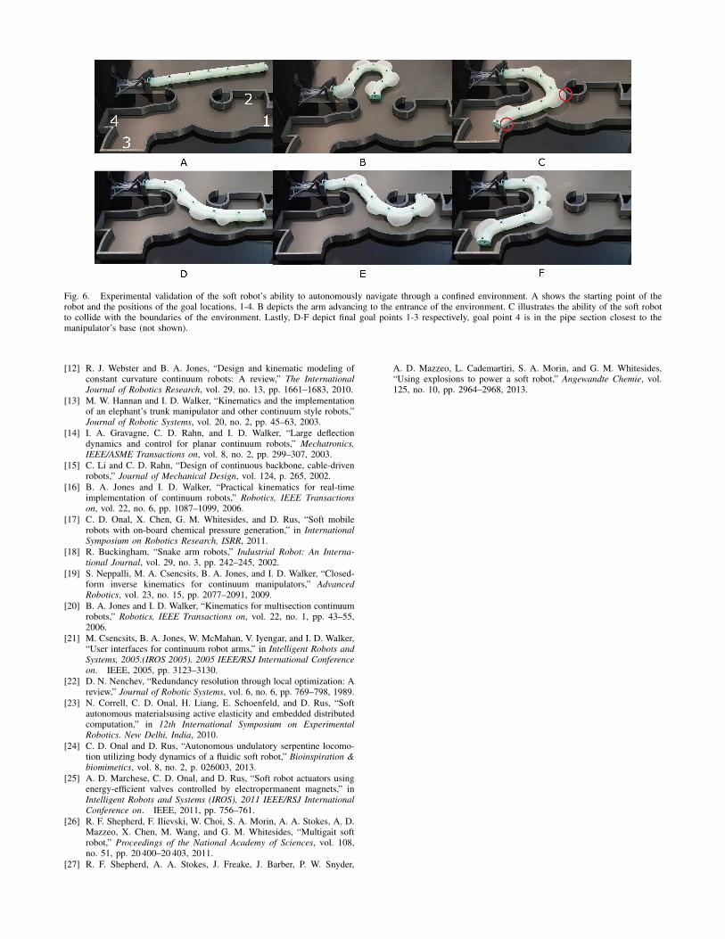
Fig. 6. Experimental validation of the soft robot’s ability to autonomously navigate through a confined environment. A shows the starting point of therobot and the positions of the goal locations, 1-4. B depicts the arm advancing to the entrance of the environment. C illustrates the ability of the soft robotto collide with the boundaries of the environment. Lastly, D-F depict final goal points 1-3 respectively, goal point 4 is in the pipe section closest to themanipulator’s base (not shown).
[12] R. J. Webster and B. A. Jones, “Design and kinematic modeling ofconstant curvature continuum robots: A review,” The InternationalJournal of Robotics Research, vol. 29, no. 13, pp. 1661–1683, 2010.
[13] M. W. Hannan and I. D. Walker, “Kinematics and the implementationof an elephant’s trunk manipulator and other continuum style robots,”Journal of Robotic Systems, vol. 20, no. 2, pp. 45–63, 2003.
[14] I. A. Gravagne, C. D. Rahn, and I. D. Walker, “Large deflectiondynamics and control for planar continuum robots,” Mechatronics,IEEE/ASME Transactions on, vol. 8, no. 2, pp. 299–307, 2003.
[15] C. Li and C. D. Rahn, “Design of continuous backbone, cable-drivenrobots,” Journal of Mechanical Design, vol. 124, p. 265, 2002.
[16] B. A. Jones and I. D. Walker, “Practical kinematics for real-timeimplementation of continuum robots,” Robotics, IEEE Transactionson, vol. 22, no. 6, pp. 1087–1099, 2006.
[17] C. D. Onal, X. Chen, G. M. Whitesides, and D. Rus, “Soft mobilerobots with on-board chemical pressure generation,” in InternationalSymposium on Robotics Research, ISRR, 2011.
[18] R. Buckingham, “Snake arm robots,” Industrial Robot: An Interna-tional Journal, vol. 29, no. 3, pp. 242–245, 2002.
[19] S. Neppalli, M. A. Csencsits, B. A. Jones, and I. D. Walker, “Closed-form inverse kinematics for continuum manipulators,” AdvancedRobotics, vol. 23, no. 15, pp. 2077–2091, 2009.
[20] B. A. Jones and I. D. Walker, “Kinematics for multisection continuumrobots,” Robotics, IEEE Transactions on, vol. 22, no. 1, pp. 43–55,2006.
[21] M. Csencsits, B. A. Jones, W. McMahan, V. Iyengar, and I. D. Walker,“User interfaces for continuum robot arms,” in Intelligent Robots andSystems, 2005.(IROS 2005). 2005 IEEE/RSJ International Conferenceon. IEEE, 2005, pp. 3123–3130.
[22] D. N. Nenchev, “Redundancy resolution through local optimization: Areview,” Journal of Robotic Systems, vol. 6, no. 6, pp. 769–798, 1989.
[23] N. Correll, C. D. Onal, H. Liang, E. Schoenfeld, and D. Rus, “Softautonomous materialsusing active elasticity and embedded distributedcomputation,” in 12th International Symposium on ExperimentalRobotics. New Delhi, India, 2010.
[24] C. D. Onal and D. Rus, “Autonomous undulatory serpentine locomo-tion utilizing body dynamics of a fluidic soft robot,” Bioinspiration &biomimetics, vol. 8, no. 2, p. 026003, 2013.
[25] A. D. Marchese, C. D. Onal, and D. Rus, “Soft robot actuators usingenergy-efficient valves controlled by electropermanent magnets,” inIntelligent Robots and Systems (IROS), 2011 IEEE/RSJ InternationalConference on. IEEE, 2011, pp. 756–761.
[26] R. F. Shepherd, F. Ilievski, W. Choi, S. A. Morin, A. A. Stokes, A. D.Mazzeo, X. Chen, M. Wang, and G. M. Whitesides, “Multigait softrobot,” Proceedings of the National Academy of Sciences, vol. 108,no. 51, pp. 20 400–20 403, 2011.
[27] R. F. Shepherd, A. A. Stokes, J. Freake, J. Barber, P. W. Snyder,
A. D. Mazzeo, L. Cademartiri, S. A. Morin, and G. M. Whitesides,“Using explosions to power a soft robot,” Angewandte Chemie, vol.125, no. 10, pp. 2964–2968, 2013.