wheels and castors catalogue - agint · today brauer wheels and castors are found ... over the...
TRANSCRIPT
WHEELS ANDCASTORS
www.brauer.co.uk
CALL US AT: 00 44 (0)1908 374022 OR FAX US AT: 00 44 (0)1908 641628CALL US AT: 00 44 (0)1908 374022 OR FAX US AT: 00 44 (0)1908 641628
INTRODUCTION
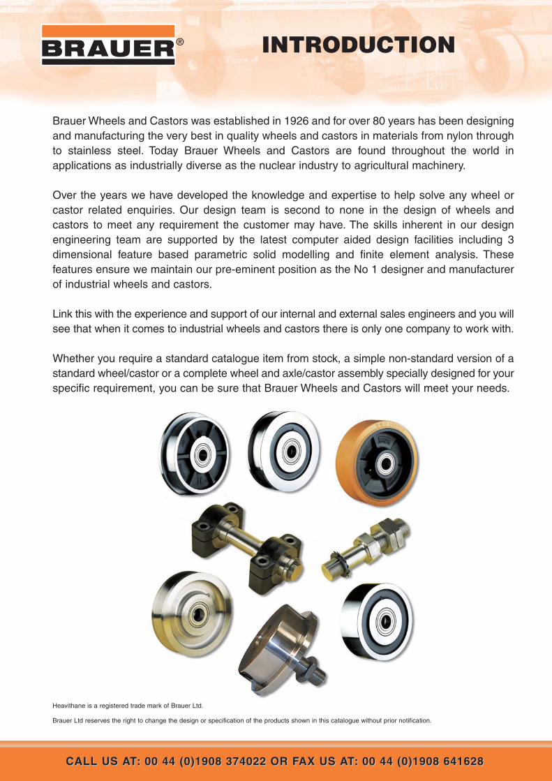
Brauer Wheels and Castors was established in 1926 and for over 80 years has been designingand manufacturing the very best in quality wheels and castors in materials from nylon throughto stainless steel. Today Brauer Wheels and Castors are found throughout the world inapplications as industrially diverse as the nuclear industry to agricultural machinery.
Over the years we have developed the knowledge and expertise to help solve any wheel orcastor related enquiries. Our design team is second to none in the design of wheels andcastors to meet any requirement the customer may have. The skills inherent in our designengineering team are supported by the latest computer aided design facilities including 3dimensional feature based parametric solid modelling and finite element analysis. Thesefeatures ensure we maintain our pre-eminent position as the No 1 designer and manufacturerof industrial wheels and castors.
Link this with the experience and support of our internal and external sales engineers and you willsee that when it comes to industrial wheels and castors there is only one company to work with.
Whether you require a standard catalogue item from stock, a simple non-standard version of astandard wheel/castor or a complete wheel and axle/castor assembly specially designed for yourspecific requirement, you can be sure that Brauer Wheels and Castors will meet your needs.
®
Heavithane is a registered trade mark of Brauer Ltd.
Brauer Ltd reserves the right to change the design or specification of the products shown in this catalogue without prior notification.

APPLICATION AND EXAMPLES 6 - 18
DESIGN SERVICE OUTLINE AND DATA 18 - 31
WHEELS & AXLE ASSEMBLIES 32 - 92
11WEB: www.brauer.co.uk EMAIL: [email protected]: www.brauer.co.uk EMAIL: [email protected]
IND
EX
IND
EX
®INDEX
Steel Single FlangedRail Wheels Page 33 - 35
Series . . . . . . . . . . . . . . . . . . . . . . . . . ‘SSF’
Wheel Dia . . . . . . . . . . . . . . . . . . . Ø75-600
Load Range . . . . . . . . . . . . . . 975-30900Kg
Cast Iron Single FlangedRail Wheels Page 36 - 38
Series . . . . . . . . . . . . . . . . . . . . . . . . . ‘CSF’
Wheel Dia . . . . . . . . . . . . . . . . . . . Ø63-300
Load Range . . . . . . . . . . . . . . . 200-2300Kg
Steel Double FlangedRail Wheels Page 39 - 42
Series . . . . . . . . . . . . . . . . . . . . . . . . . ‘SDF’
Wheel Dia . . . . . . . . . . . . . . . . . . . Ø75-600
Load Range . . . . . . . . . . . . . 1350-30900Kg
Cast Iron Double FlangedRail Wheels Page 43 - 44
Series . . . . . . . . . . . . . . . . . . . . . . . . . ‘CDF’
Wheel Dia . . . . . . . . . . . . . . . . . . Ø130-300
Load Range . . . . . . . . . . . . . . . 650-2300Kg
Steel Flat TreadRail Wheels Page 45 - 47
Series . . . . . . . . . . . . . . . . . . . . . . . . . ‘SFT’
Wheel Dia . . . . . . . . . . . . . . . . . . . Ø75-600
Load Range . . . . . . . . . . . . . 2300-46300Kg
Steel ‘V’ GroovedWheels Page 54 - 55
Series . . . . . . . . . . . . . . . . . . . . . . . . . ‘SVT’
Wheel Dia . . . . . . . . . . . . . . . . . . . Ø75-300
Load Range . . . . . . . . . . . . . . . 800-7100Kg
Polyurethane TyredSingle-flangedRail Wheels Page 56 - 57
Series . . . . . . . . . . . . . . . . . . . . . . . . . ‘SFH’
Wheel Dia . . . . . . . . . . . . . . . . . . Ø100-200
Load Range . . . . . . . . . . . . . . . 450-1400Kg
Cast Nylon Flat TreadWheels Page 50 - 51
Series . . . . . . . . . . . . . . . . . . . . . . . . . ‘NFT’
Wheel Dia . . . . . . . . . . . . . . . . . . Ø200-400
Load Range . . . . . . . . . . . . . . 2350-7850Kg
Nylon DoubleFlanged Wheels Page 52 - 53
Series . . . . . . . . . . . . . . . . . . . . . . . . . ‘NFT’
Wheel Dia . . . . . . . . . . . . . . . . . . Ø200-400
Load Range . . . . . . . . . . . . . . 1960-4770Kg
Cast Iron Flat TreadRail Wheels Page 48 - 49
Series . . . . . . . . . . . . . . . . . . . . . . . . . ‘CFT’
Wheel Dia . . . . . . . . . . . . . . . . . . Ø130-300
Load Range . . . . . . . . . . . . . . 1200-4000Kg
22 WEB: www.brauer.co.uk EMAIL: [email protected]: www.brauer.co.uk EMAIL: [email protected]
IND
EX
IND
EX
® INDEX
Polyurethane TyredWheels Page 68 - 73
Series . . . . . . . . . . . . . . . . . . . . . . . . . . . ‘H’
Wheel Dia . . . . . . . . . . . . . . . . . . . Ø75-460
Load Range . . . . . . . . . . . . . . . 300-5200Kg
Material HandlingTruck Wheels Page 74
Wheel Dia . . . . . . . . . . . . . . . . . . Ø150-350
Polyurethane ‘Press-On-BandTyred Wheels Page 81 - 84
Series . . . . . . . . . . . . . . . . . . . . . . . . . . ‘PH’
Wheel Dia . . . . . . . . . . . . . . . . . . Ø250-500
Load Range . . . . . . . . . . . . . . 2000-4800Kg
WHEELS & AXLE ASSEMBLIES (continued) 32 - 92
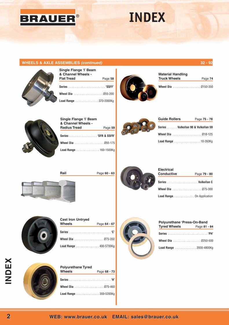
Cast Iron UntryedWheels Page 64 - 67
Series . . . . . . . . . . . . . . . . . . . . . . . . . . . ‘C’
Wheel Dia . . . . . . . . . . . . . . . . . . . Ø75-350
Load Range . . . . . . . . . . . . . . . 400-5700Kg
Single Flange ‘I’ Beam& Channel Wheels -Radius Tread Page 59
Series . . . . . . . . . . . . . . . . . . ‘SFR & SSFR’
Wheel Dia . . . . . . . . . . . . . . . . . . . Ø55-175
Load Range . . . . . . . . . . . . . . . 160-1500Kg
Rail Page 60 - 63
Single Flange ‘I’ Beam& Channel Wheels -Flat Tread Page 58
Series . . . . . . . . . . . . . . . . . . . . . . . . ‘SSFF’
Wheel Dia . . . . . . . . . . . . . . . . . . . Ø55-200
Load Range . . . . . . . . . . . . . . . 370-2000Kg
Guide Rollers Page 75 - 78
Series . . . . . . . Vulkollan 90 & Vulkollan 59
Wheel Dia . . . . . . . . . . . . . . . . . . . Ø18-125
Load Range . . . . . . . . . . . . . . . . . 10-260Kg
ElectricalConductive Page 79 - 80
Series . . . . . . . . . . . . . . . . . . . . Vulkollan C
Wheel Dia . . . . . . . . . . . . . . . . . . . Ø75-300
Load Range. . . . . . . . . . . . . . On Application

33WEB: www.brauer.co.uk EMAIL: [email protected]: www.brauer.co.uk EMAIL: [email protected]
IND
EX
IND
EX
®INDEX
Rubber TyredWheels Page 85 - 86
Series . . . . . . . . . . . . . . . . . . . . . . . . . . . ‘R’
Wheel Dia . . . . . . . . . . . . . . . . . . Ø100-200
Load Range . . . . . . . . . . . . . . . . 120-400Kg
Rubber Tyred‘Press-on Band’ Page 87
Series . . . . . . . . . . . . . . . . . . . . . . . . . . ‘PR’
Band Dia Range . . . . . . . . . . . . . . Ø380-460
Load Range . . . . . . . . . . . . . . 1240-1470Kg
Untyred NylonWheels Page 88
Series . . . . . . . . . . . . . . . . . . . . . . . . . . . ‘N’
Wheel Dia . . . . . . . . . . . . . . . . . . . Ø50-250
Load Range . . . . . . . . . . . . . . . . 80-2000Kg
WHEELS & AXLE ASSEMBLIES (continued) 32 - 92
H7 TOLERANCE
GRUB SCREWS
ANTI-HYDROLYSIS TO POLYURETHANE
FLAT TREAD OPTIONS
THROUGH AXLE GREASE (TAG)
CROWN TREAD ON POLY WHEELS
FLAME HARDENING
AVAILABLE ADDITIONS TO STANDARD SPECIFICATIONS
Axle Brackets Page 89
Series. . . . . . . . . . . . . . . . . . . . . . . . ‘B’
Load Range . . . . . . . . . . . . Up To 20000Kg
Twin Wheel Axle Assemblies Page 90
Series . . . . . . . . . . . . . . . . . . . . . . . . . . . ‘A’
Load Range . . . . . . . . . . . . Up To 12000Kg
Single Wheel Axle Assemblies Page 91
Series . . . . . . . . . . . . . . . . . . . . . . . . . . ‘BA’
Load Range . . . . . . . . . . . . Up To 40000Kg
Cantilevered StubAxle Assemblies Page 92
Series .....................................................‘CA’
Wheel Dia .............................Up To 1100Kg

44 CALL US AT: 00 44 (0)1908 374022 OR FAX US AT: 00 44 (0)1908 641628CALL US AT: 00 44 (0)1908 374022 OR FAX US AT: 00 44 (0)1908 641628
IND
EX
IND
EX
® INDEX
Pneumatic Tyred CastorTwin Wheel Page 96
Series . . . . . . . . . . . . . . . . . . . . . . . . . ‘TQZ’
Wheel Dia . . . . . . . . . . . . . . . . . . . . . . Ø535
Load Range . . . . . . . . . . . . . . Up to 4200Kg
Pneumatic Tyred CastorSingle Wheel Page 95
Series . . . . . . . . . . . . . . . . . . . . . . . . . . ‘WG’
Wheel Dia . . . . . . . . . . . . . . . . . . . . . . Ø535
Load Range . . . . . . . . . . . . . . Up to 2100Kg
INDUSTRIAL CASTORS 93 - 111
GG Series with Various WheelsSwivel load Rating 1500Kg Page 105
Series . . . . . . . . . . . . . . . . . . . . . . . . . . ‘GG’
Wheel Dia . . . . . . . . . . . . . . . . . . Ø100-250
Load Range . . . . . . . . . . . . . . . 450-1500Kg
Pivoting Castors Page 97
Designed to Order
Load Range Up to and exceeding 200 Tonne
TWG Series with Various WheelsSwivel load Rating 3000Kg Page 103
Series . . . . . . . . . . . . . . . . . . . . . ‘TWG’
Wheel Dia . . . . . . . . . . . . . . . . . . . . . . Ø150
Load Range . . . . . . . . . . . . . . 1200 -3000Kg
WG Series with Various WheelsSwivel load Rating 3000Kg Page 104
Series . . . . . . . . . . . . . . . . . . . . . . . . . . ‘WG’
Wheel Dia . . . . . . . . . . . . . . . . . . Ø150-300
Load Range . . . . . . . . . . . . . . . 900-3000Kg
UHQZ Series with VariousWheelsSwivel load Rating 12000Kg Page 99
Series . . . . . . . . . . . . . . . . . . . . . . . . ‘UHQZ’
Wheel Dia . . . . . . . . . . . . . . . . . . Ø350-500
Load Range . . . . . . . . . . . . . 6400-12000Kg
HQZ Series with Various WheelsSwivel load Rating 7300Kg Page 100
Series . . . . . . . . . . . . . . . . . . . . . . . . . ‘HQZ’
Wheel Dia . . . . . . . . . . . . . . . . . Ø200-3805
Load Range . . . . . . . . . . . . . . 6200-7300Kg
TQZ Series with Various WheelsSwivel load Rating 5100Kg Page 101
Series . . . . . . . . . . . . . . . . . . . . . . . . . ‘TQZ’
Wheel Dia . . . . . . . . . . . . . . . . . . Ø200-300
Load Range . . . . . . . . . . . . . . 4000-5100Kg
QZ Series with Various WheelsSwivel load Rating 4200Kg Page 102
Series . . . . . . . . . . . . . . . . . . . . . . . . . . ‘QZ’
Wheel Dia . . . . . . . . . . . . . . . . . . Ø200-380
Load Range . . . . . . . . . . . . . . 3100-4200Kg

55WEB: www.brauer.co.uk EMAIL: [email protected]: www.brauer.co.uk EMAIL: [email protected]
IND
EX
IND
EX
®INDEX
Floor Locks Page 111
Series . . . . . . . . . . . . . . . . . . . . . . . . . . . ‘FL’
Wheel Dia . . . . . . . . . . . . . . . . . . Ø100-150
F Series with Various WheelsFixed or Swivel Page 110
Series’. . . . . . . . . . . . . . . . . . . . . . . . . . . FS’
Wheel Dia . . . . . . . . . . . . . . . . . . . Ø63-150
Load Range . . . . . . . . . . . . . . . . 120-360Kg
LG Series with PolyurethaneTyred Wheel Page 106
Series . . . . . . . . . . . . . . . . . . . . . . . . . . ‘LG’
Wheel Dia . . . . . . . . . . . . . . . . . . Ø125-150
Load Range . . . . . . . . . . . . . . . . 400-600Kg
H Series with PolyurethaneTyred Wheel Swivel Page 109
Series . . . . . . . . . . . . . . . . . . . . . . . . . . ‘HS’
Wheel Dia . . . . . . . . . . . . . . . . . . Ø100-300
Load Range . . . . . . . . . . . . . . . 500-1500Kg
H Series with PolyurethaneTyred Wheel Fixed Page 109
Series . . . . . . . . . . . . . . . . . . . . . . . . . . ‘HF’
Wheel Dia . . . . . . . . . . . . . . . . . . Ø100-300
Load Range . . . . . . . . . . . . . . . 500-1500Kg
2500Kg Jacking Unit Page 107
Series . . . . . . . . . . . . . . . . . . . . . . ‘JU2500’
Wheel Dia . . . . . . . . . . . . . . . . . . Ø150-300
Load Range . . . . . . . . . . . . . . Up to 2500Kg
1000Kg Jacking Unit Page 108
Series . . . . . . . . . . . . . . . . . . . . . . ‘JU1000’
Wheel Dia . . . . . . . . . . . . . . . . . . Ø150-250
Load Range . . . . . . . . . . . . . . Up to 1000Kg
INDUSTRIAL CASTORS (continued) 93 - 111
66 CALL US AT: 00 44 (0)1908 374022 OR FAX US AT: 00 44 (0)1908 641628CALL US AT: 00 44 (0)1908 374022 OR FAX US AT: 00 44 (0)1908 64162866
® Applications and ExamplesA
PP
LIC
AT
ION
S A
ND
EX
AM
PL
ES
AP
PL
ICA
TIO
NS
AN
D E
XA
MP
LE
S

77CALL US AT: 00 44 (0)1908 374022 OR FAX US AT: 00 44 (0)1908 641628CALL US AT: 00 44 (0)1908 374022 OR FAX US AT: 00 44 (0)1908 641628
AP
PL
ICA
TIO
NS
AN
D E
XA
MP
LE
SA
PP
LIC
AT
ION
S A
ND
EX
AM
PL
ES
77WEB: www.brauer.co.uk EMAIL: [email protected]: www.brauer.co.uk EMAIL: [email protected]
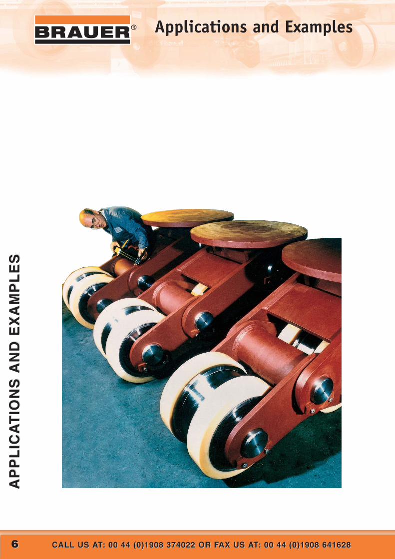
®Applications and Examples
Brauer Ltd manufactured according tothe design specification of J Murphyand Sons Limited, Gas pipe tunneltrollies for the gas ring mainimprovement to the west of Londonfrom Harefield to Southall for theNational Grid.
The gas pipe is required to bepush/pulled into position andstatically supported whilst empty(565kg/m), until the tunnel annulus isfilled, the trollies must also supportthe pipe when filled with water tosupport hydro testing (1735kg/m)
The 4 sections of the tunnel havelengths of 974m, 756m, 505m and207m respectively and the totalimprovement section is 27 kilometres
The bored tunnel of concrete sectionwas 2.2m diameter and the gas pipewithin this tunnel was 1.2m diameterleaving very limited space betweenthe two, so the gas pipe supportingtrollies had to be small enough toenter this gap between the pipe andthe tunnels walls but have very highloading capacity to take the gas pipeas it was pulled/pushed into the outertunnel. The rail system for the trollieswas laid on a bed of silicon sand.
Brauer Ltd provided a total solution of88 low height / high load capacitytrollies which ranged from 10,000Kgeach to 22,000Kg each.

88 CALL US AT: 00 44 (0)1908 374022 OR FAX US AT: 00 44 (0)1908 641628CALL US AT: 00 44 (0)1908 374022 OR FAX US AT: 00 44 (0)1908 641628
AP
PL
ICA
TIO
NS
AN
D E
XA
MP
LE
SA
PP
LIC
AT
ION
S A
ND
EX
AM
PL
ES
® Applications and Examples
7600 tonne, 32 meterdiameter, pipe laying turntablerunning on 330 steel doubleflange rail wheels fitted withself-lubricating bushes andstainless steel shafts. Tread diameter 450mm.Tread width 112mm wide with crown profile to assisttracking. Tread and inner flange flamehardened to ensure a servicewear life in excess of sevenyears.

99WEB: www.brauer.co.uk EMAIL: [email protected]: www.brauer.co.uk EMAIL: [email protected]
AP
PL
ICA
TIO
NS
AN
D E
XA
MP
LE
SA
PP
LIC
AT
ION
S A
ND
EX
AM
PL
ES
®Applications and Examples
This ship mounted pipe laying turntablewhich is running on three rings of taperedtread steel wheels mounted in a fixedframe. The wheels and frame are finished inmarine specification paint. Total weightwhen loaded is 600 tonnes with each wheeland bracket capable of carrying 50 tonnes.
Ship mounted cable and pipe carousels usedin the offshore wind farm, renewable energyand energy supply industries loaded capacitiesbetween 2,500 tonnes to 15,000 tonnes

1010 CALL US AT: 00 44 (0)1908 374022 OR FAX US AT: 00 44 (0)1908 641628CALL US AT: 00 44 (0)1908 374022 OR FAX US AT: 00 44 (0)1908 641628
AP
PL
ICA
TIO
NS
AN
D E
XA
MP
LE
SA
PP
LIC
AT
ION
S A
ND
EX
AM
PL
ES
® Applications and Examples
A ship lift and transfer dock system forremoving ships from the sea and thentransferring ships around the dock for repairand maintenance to take place. Three sizes ofwheels are used througout the dock.
Rated LoadSDF 450/95/TBM75FH + AXLE 25500 Kg
SDF 350/85/TBM75FH + AXLE 19500 Kg
SDF 250/80/TBM50FH + AXLE 13000 Kg
FH = Flame Hardened
The SDF 250 and 350 being primarily used onthe ship lift trolley with the SDF 450 mainly onthe transfer system. The wheels have beensimplified and redesigned to ensure longer life,easier installation and lower maintenance.

1111WEB: www.brauer.co.uk EMAIL: [email protected]: www.brauer.co.uk EMAIL: [email protected]
AP
PL
ICA
TIO
NS
AN
D E
XA
MP
LE
SA
PP
LIC
AT
ION
S A
ND
EX
AM
PL
ES
®Applications and Examples
Multi-pivoting, dual purpose castor with directionalswivel top plate. Fitted with 4 steel double flange railwheels, 450mm tread diameter and 90mm tread widthand 8 anti-hydrolysis polyurethane tyred wheels,505mm tread diameter and 150mm tread width.All axles are ground stainless steel running in selflubricating nylon bushes.
Load Ratinga) When mounted on rail and running on the double
flange wheels – 160 tonne per castor assembly.b) When running on polyurethane tyred wheels – 76.8
tonne per castor assembly.
Wheel and axle assemblies used in a rotating drumapplication. Given the extreme conditions and highloadings involved the wheels and axles have beenspecifically designed to the customers requirements thatdemand flat tread wheels with axles that are capable oftaking a load in excess of 75 tonnes.
The wheels shown are SFT600/250/KM150 with an axleØ150mm reducing to 100mm for the bearing housing.
1212 CALL US AT: 00 44 (0)1908 374022 OR FAX US AT: 00 44 (0)1908 641628CALL US AT: 00 44 (0)1908 374022 OR FAX US AT: 00 44 (0)1908 641628
AP
PL
ICA
TIO
NS
AN
D E
XA
MP
LE
SA
PP
LIC
AT
ION
S A
ND
EX
AM
PL
ES
® Applications and Examples
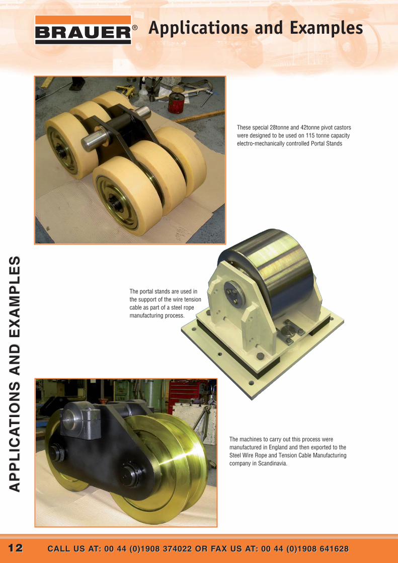
These special 28tonne and 42tonne pivot castorswere designed to be used on 115 tonne capacityelectro-mechanically controlled Portal Stands
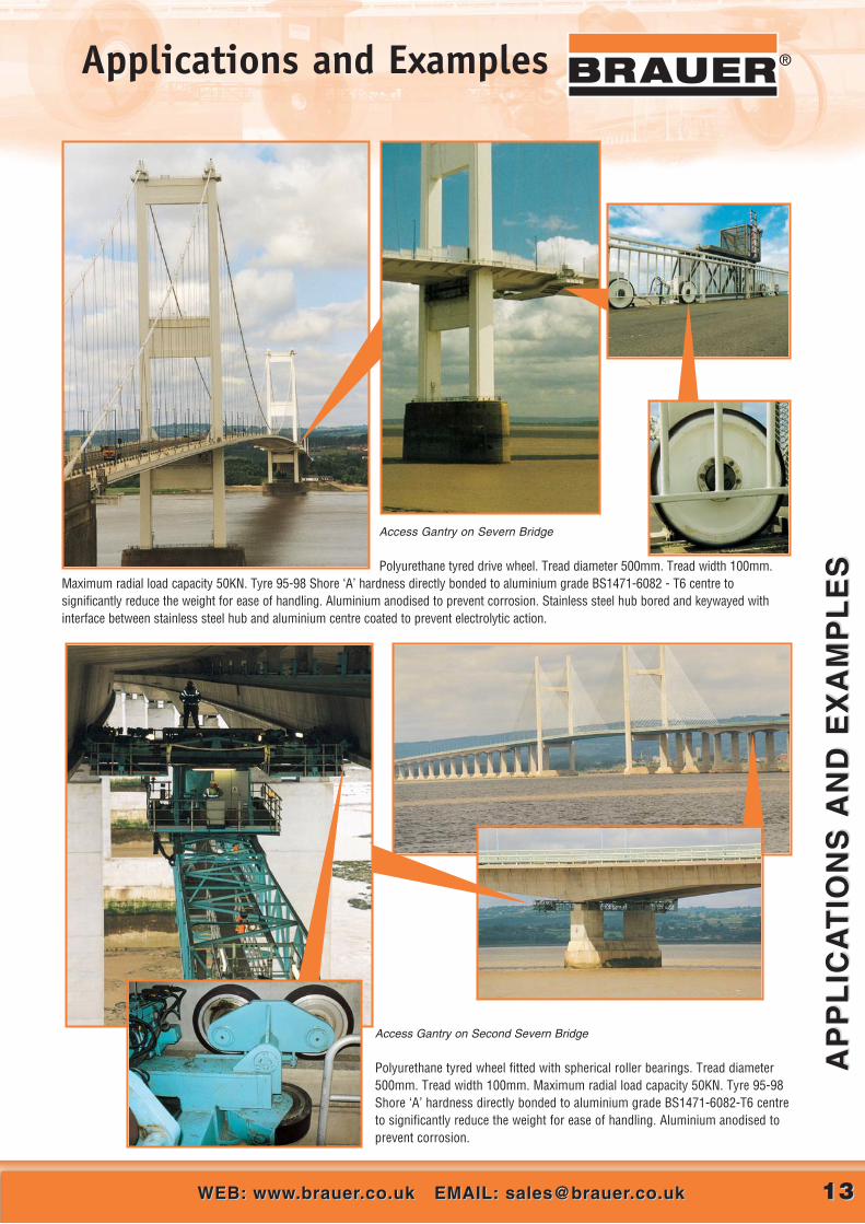
The portal stands are used inthe support of the wire tensioncable as part of a steel ropemanufacturing process.
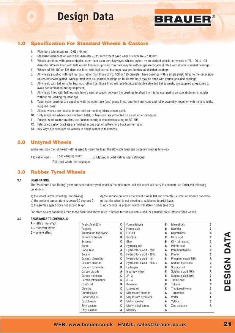
The machines to carry out this process weremanufactured in England and then exported to theSteel Wire Rope and Tension Cable Manufacturingcompany in Scandinavia.
1313WEB: www.brauer.co.uk EMAIL: [email protected]: www.brauer.co.uk EMAIL: [email protected]
AP
PL
ICA
TIO
NS
AN
D E
XA
MP
LE
SA
PP
LIC
AT
ION
S A
ND
EX
AM
PL
ES
®Applications and Examples
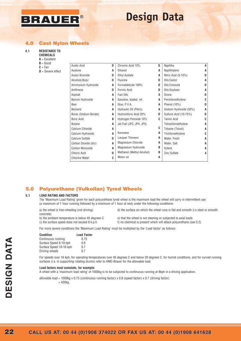
Access Gantry on Severn Bridge
Polyurethane tyred drive wheel. Tread diameter 500mm. Tread width 100mm.Maximum radial load capacity 50KN. Tyre 95-98 Shore ‘A’ hardness directly bonded to aluminium grade BS1471-6082 - T6 centre tosignificantly reduce the weight for ease of handling. Aluminium anodised to prevent corrosion. Stainless steel hub bored and keywayed withinterface between stainless steel hub and aluminium centre coated to prevent electrolytic action.
Access Gantry on Second Severn Bridge
Polyurethane tyred wheel fitted with spherical roller bearings. Tread diameter500mm. Tread width 100mm. Maximum radial load capacity 50KN. Tyre 95-98Shore ‘A’ hardness directly bonded to aluminium grade BS1471-6082-T6 centreto significantly reduce the weight for ease of handling. Aluminium anodised toprevent corrosion.

1414 CALL US AT: 00 44 (0)1908 374022 OR FAX US AT: 00 44 (0)1908 641628CALL US AT: 00 44 (0)1908 374022 OR FAX US AT: 00 44 (0)1908 641628
AP
PL
ICA
TIO
NS
AN
D E
XA
MP
LE
SA
PP
LIC
AT
ION
S A
ND
EX
AM
PL
ES
® Applications and Examples
Fixed castor fitted with 686mm diameter EN24T steel wheel with composite PTFE bush running on ground stainless steel axle. Castor loading capacity 200 tonne.
Pivoting castor with swivel head fitted with twoEN24T single flange rail wheels complete with
wheel brakes. Tread diameter 280mm.
Tread width 87.5mm. Tread flame hardened.
Maximum load rating per castor 45000Kg.
Swing bridge on Caledonian Canal
at Fort Augustus

1515WEB: www.brauer.co.uk EMAIL: [email protected]: www.brauer.co.uk EMAIL: [email protected]
AP
PL
ICA
TIO
NS
AN
D E
XA
MP
LE
SA
PP
LIC
AT
ION
S A
ND
EX
AM
PL
ES
®Applications and Examples
Bridge scraper forrectangularsettlement tank
Steel double flangerail wheels SDF450/80
Half Bridge scraper for
rotary settlement tank
Both drive and trailingwheels standardpolyurethane tyredwheels H300/75 boredand keywayed.

1616 CALL US AT: 00 44 (0)1908 374022 OR FAX US AT: 00 44 (0)1908 641628CALL US AT: 00 44 (0)1908 374022 OR FAX US AT: 00 44 (0)1908 641628
AP
PL
ICA
TIO
NS
AN
D E
XA
MP
LE
SA
PP
LIC
AT
ION
S A
ND
EX
AM
PL
ES
® Applications and Examples
Wheels and axles supplied forthe maintenace of dryertransfer cars for brickmanufacturing plant. Brauersupplied complete wheel andaxle assemblies thatcomprised Steel DoubleFlanged and Steel Flat TreadWheels.
In addition to the applicationshown Brauer have beeninstrumental in thereplacement of wheels andongoing maintenace of severalother key areas of the plant.The solutions provided havehelped to solve certainirritating problems andremoved unnecessarydowntime on the productionline resulting in considerablesavings to the company.
Drum supported onfour twin wheel axle
assemblies eachconsisting of two
polyurethane ‘Press-on-Band’ tyred wheels
PH460/75 fitted to amodified BA75 axle
assembly
Drum supportedon four pivoting
castors eachfitted with two
polyurethanetyred wheels
H200/60.
Aggregate Screening
Machine

1717WEB: www.brauer.co.uk EMAIL: [email protected]: www.brauer.co.uk EMAIL: [email protected]
AP
PL
ICA
TIO
NS
AN
D E
XA
MP
LE
SA
PP
LIC
AT
ION
S A
ND
EX
AM
PL
ES
®Applications and Examples
Wheel options of Cast Iron,Steel or AluminiumVulkollan superiorpolyurethane is used as thestandard tyre material.Tyrescan be produced withcrown/dome treads to suitspecific applications.Bore options available forall standard wheels fittedwith precisionbearings.Operatingtemperature range -20C° to+60C°.Hardness of tyre of92 ±3° shore ‘A’.

1818 CALL US AT: 00 44 (0)1908 374022 OR FAX US AT: 00 44 (0)1908 641628CALL US AT: 00 44 (0)1908 374022 OR FAX US AT: 00 44 (0)1908 641628
AP
PL
ICA
TIO
NS
AN
D E
XA
MP
LE
SA
PP
LIC
AT
ION
S A
ND
EX
AM
PL
ES
® Our Design Service
We offer a comprehensive design,engineering and manufacturing service toresolve your application problem eitherfrom our extensive range of standardproducts or products specifically designedfor the application
• Wheels and castors designed to suit any environment.
• Computer aided design facilities include 3 dimensional feature basedparametric solid modelling and finite element analysis.
• Life calculations for steel rail wheels.
• Non-standard wheels can often be designed from our extensive stock ofcastings, blanks, and part-machined and tyred wheels.
• Wheels, axle assemblies and castors can be designed andmanufactured to suit any loading and in most materials includingstainless steel, aluminium, titanium, nickel chromium alloys, etc.
• Polyurethane tyres can be bonded onto most metal centres includingaluminium, titanium, stainless steel and various ferrous andnon-ferrous alloys.
• Polyester/Polyether Polymeric tyre compounds can be produced inNapthalene Diisocyanate (N.D.I), Toluene Diisocyanate (T.D.I) andDiphenylmethane Diisocyanate (M.D.I).
• All types of bearing and bushes can be incorporated into the design.
• Steel wheels and fabrications can be plated in blue or gold zincpassivation, cadmium, electroless nickel, chrome, etc. or finished toany paint specification.
• Non-destructive testing such as ‘X’ Ray, ultrasonic or magneticparticle detection is available on request.
What We Offer...
EMAIL [email protected] OR COPY, COMPLETE AND SENDTO US THE APPLICATION DATA FORM OPPOSITE

1919WEB: www.brauer.co.uk EMAIL: [email protected]: www.brauer.co.uk EMAIL: [email protected]
OU
R D
ES
IGN
SE
RV
ICE
O
UR
DE
SIG
N S
ER
VIC
E
®®Application Data Form(use to get you started, or fill it in and send it back to us)
ApplicationDescription of applicationNo. of wheels per assemblyTotal weight of assembly KgIs the load evenly distributedRadial load per wheel KgAxial load per wheel KgFunction of wheel Driving Steering SupportingRunning Surface Concrete Tarmac Steel Plate
Rail Other (specify)Rail type Useable rail width mmSpeed of wheel rpm KphFrequency of use (hour per day) (cycles per day)Service life required hoursEnvironment Temperature deg C Dusty Humid %
(if over 110 deg C see below)Immersed in water Other (specify)
Rotating DrumDrum mass KgCharge mass KgDrum diameter mmDrum Speed rpm KphWheel angle from vert C/L deg
WheelStyle of wheel Tyred Flat tread Single flange
Double flangeWheel dimensions Tread dia mm Tread width mm Hub width
Axle diaWheel material Carbon or alloy steel Cast Iron Stainless Steel
Other (specify)Finish Steel (air dry oil) Cast Iron (black etch primer)
Other (specify)
BoreDiameter mm Brauer to defineBearing requirements Bearing Bush Plain boreBearing type Ball Taper roller Spherical roller
Sealed Other (specify)Bush type Plain bronze Self lub. Nylon
Other (specify)Greasing requirement Through wheel Through axle Sealed for life
None
AxleAre axle or axle brackets required?Axle type ‘A’ style ‘BA’ style ‘CA’ style
‘SFR’ style ‘Castor’ style Other (specify)Axle material Standard (En16 type) Other (specify)
CastorIs a castor assembly required?Castor type? (specify)Top plate flatnessFinish Fabrication (black etch primer)
High Temperature ApplicationWhere the working temperature is to exceed 110 deg C, the following data should be provided.Type of bearing required Plain bearing (bush) Flanged bush Ball bearingMaximum working temp deg CIs the wheel working (rotating) at this temperature under full load?Does the wheel work at a lower temperature, but remains static under load at max temperature?What period of time does the wheel remain under load at the maximum temperature?
Maintenance Free? Grease Free?
NAME: POSITION IN COMPANY:
COMPANY NAME AND ADDRESS:
TELEPHONE NO. FAX NO. EMAIL

2020 WEB: www.brauer.co.uk EMAIL: [email protected]: www.brauer.co.uk EMAIL: [email protected]
WH
EE
LS
AN
D C
AS
TO
RS
WH
EE
LS
AN
D C
AS
TO
RS
® Design Service Index
Contents
1.0 Specification For Standard Wheels & Castors..............................................................................21
2.0 Untyred Wheels ............................................................................................................................21
3.0 Rubber Tyred Wheels ...................................................................................................................213.1 Load Rating ...........................................................................................................................213.2 Resistance to Chemicals ............................................................................................................21
4.0 Cast Nylon Wheels .......................................................................................................................224.1 resistance to chemicals .............................................................................................................22
5.0 Polyurethane Tyred Wheels ..........................................................................................................225.1 Load Rating ...........................................................................................................................225.2 Resistance to Chemicals ............................................................................................................23
6.0 Rail Wheels ..................................................................................................................................236.1 Approximation of Allowable Load (catalogue items) ............................................................................236.2 Calculation of Allowable Load - Steel and S.G. Iron Rail Wheels ..........................................................24-256.3 Calculation of Allowable Load - Cast Iron Rail Wheels ..........................................................................266.4 Surface Hardening ...................................................................................................................266.5 Flange Strength.......................................................................................................................26
7.0 Bearing and Seal Arrangements - Non Standard..........................................................................267.1 Selection of Bearings ................................................................................................................267.2 Bearing Seals .........................................................................................................................27
8.0 Inertial and Rolling Resistance.....................................................................................................278.1 Rolling Friction .......................................................................................................................278.2 Bearing Friction.......................................................................................................................288.3 Inertial Resistance ...................................................................................................................28
9.0 Traction - Coefficients of Friction .................................................................................................28
10.0 Load Calculations for Wheels Supporting and/or Driving Drums.................................................28
11.0 Keyway Dimensions .....................................................................................................................29
12.0 Reference Tables and Conversion Factors....................................................................................2912.1 Steel Hardness / Tensile Strength..................................................................................................2912.2 Tensile Strength of Heat Treated Steels ...........................................................................................2912.3 Useful Conversion Factors ..........................................................................................................29
13.0 Castors .........................................................................................................................................3013.1 Castor Arrangement ............................................................................................................30-3113.2 Load Rating ...........................................................................................................................3113.3 Manual Propulsion ...................................................................................................................3113.4 Power Towing ........................................................................................................................31
Important Note Whilst due care has been taken in compiling the following information, Brauer cannot guarantee itsdetailed accuracy, and will not accept responsibility for the results of use of any data which issubsequently found to be inaccurate.
®Design Data
DE
SIG
N D
ATA
DE
SIG
N D
ATA
2121WEB: www.brauer.co.uk EMAIL: [email protected]: www.brauer.co.uk EMAIL: [email protected]
1.0 Specification For Standard Wheels & Castors
1. Plain bore tolerances are +0.05 / -0 mm.2. Standard tolerances on width and diameter ±0.25 mm except tyred wheels which are ± 1.00mm.3. Wheels are fitted with grease nipples, other than plain bore keywayed wheels, nylon, nylon centred wheels, or wheels of 75, 100 or 125
diameter. Wheels fitted with ball journal bearings up to 40 mm bore may be without grease nipples if fitted with double shielded bearings.4. Wheels of 75, 100 or 125 diameter fitted with ball journal bearings have pre-lubricated shielded bearings.5. All wheels supplied with ball journals, other than those of 75, 100 or 125 diameter, have bearings with a single shield fitted to the outer side
unless otherwise stated. Wheels fitted with ball journal bearings up to 40 mm bore may be fitted with double shielded bearings. 6. All wheels with ball or roller bearings, other than those fitted with pre-lubricated double shielded ball journals, are supplied un-greased to
avoid contamination during shipment.7. All wheels fitted with ball journals have a central spacer between the bearings to allow them to be clamped to an axle abutment shoulder
without pre-loading the bearings.8. Taper roller bearings are supplied with the outer race (cup) press fitted, and the inner cone and roller assembly, together with metal shields,
supplied loose.9. All cast wheels are finished in one coat self-etching black primer paint.10. Fully machined wheels or axles from billet, or barstock, are protected by a coat of air-drying oil.11. Pressed steel castor brackets are finished in bright zinc electroplating to BS1706.12. Fabricated castor brackets are finished in one coat of self-etching black primer paint.13. Key ways are produced to Wheels in house standard tolerances.
2.0 Untyred WheelsWhen less than the full tread width is used to carry the load, the allowable load can be determined as follows:-
Allowable load = Load carrying width x ‘Maximum Load Rating’ (per catalogue)Full tread width (per catalogue)
3.0 Rubber Tyred Wheels
3.1 LOAD RATING.The ‘Maximum Load Rating’ given for each rubber tyred wheel is the maximum load the wheel will carry in constant use under the followingconditions:
a) the wheel is free-wheeling (not driving) d) the surface on which the wheel runs is flat and smooth (i.e steel or smooth concrete)b) the ambient temperature is below 30 degrees C. e) that the wheel is not steering or subjected to axial loadsc) the surface speed does not exceed 6 kph f) no chemical is present which will attack rubber (see 3.2)
For more severe conditions than those described above refer to Brauer for the allowable load, or consider polyurethane tyred wheels.
3.2 RESISTANCE TO CHEMICALSA = little or no effectB = moderate effectC = severe effect
Acetic Acid 20% CAcetone CAmmonium hydroxide CBarium hydroxide BBenzene CBorax ABoric Acid AButane CCalcium bisulphite C Calcium chloride ACalcium hydroxide BCarbon dioxide ACarbon monoxide CCarbon tetrachloride CCastor oil BChlorine CChromic acid CCottonseed oil CCyclohexane CEthyl acetate CEthyl alcohol A
Formaldehyde CFormic acid BFuel oil CGasoline CGlue BHydraulic oils CHydrochloric acid - cold AHydrochloric acid - 10% AHydrochloric acid - hot CHydrochloric acid - 30% + CHydrogen BIsopropyl ether CJP- 3 CJP -4 CKerosene CLinseed oil CMagnesium chloride AMagnesium hydroxide AMethyl alcohol AMethyl ethyl ketone CMercury A
Mineral oils CNaphtha CNaphthalene CNitric acid COil - lubricating CPalmic acid CPerchlorethylene CPhenol CPhosphoric acid 85% ASodium hydroxide CSoybean oil CSulphuric acid 10% ASulphuric acid 50% CTannic acid AToluene CTrichloroethylene CTurpentine CWater AXylene CZinc sulphate A
2121
2222 CALL US AT: 00 44 (0)1908 374022 OR FAX US AT: 00 44 (0)1908 641628CALL US AT: 00 44 (0)1908 374022 OR FAX US AT: 00 44 (0)1908 641628
DE
SIG
N D
ATA
DE
SIG
N D
ATA
® Design Data
4.0 Cast Nylon Wheels4.1 RESISTANCE TO
CHEMICALSA = ExcellentB = GoodC = FairD = Severe effect
Acetic Acid D
Acetone A
Acetyl Bromide D
Alcohols:Butyl D
Ammonium Hydroxide A
Antifreeze D
Asphalt A
Barium Hydroxide A
Beer A
Benzene A
Borax (Sodium Borate) A
Boric Acid B
Butane A
Calcium Chloride A
Calcium Hydroxide A
Calcium Sulfate D
Carbon Dioxide (dry) A
Carbon Monoxide A
Chloric Acid D
Chlorine Water C
Chromic Acid 10% D
Ethanol A
Ethyl Acetate A
Fluorine D
Formaldehyde 100% D
Formic Acid D
Fuel Oils A
Gasoline, leaded, ref. A
Glue, P.V.A. A
Hydraulic Oil (Petro) A
Hydrochloric Acid 20% D
Hydrogen Peroxide 10% C
Jet Fuel (JP3, JP4, JP5)C
Kerosene A
Lacquer Thinners A
Magnesium Chloride A
Magnesium Hydroxide B
Methanol (Methyl Alcohol) B
Motor oil A
Naphtha A
Naphthalene A
Nitric Acid (5-10%) D
Oils:Castor A
Oils:Creosote D
Oils:Soybean A
Ozone D
Perchloroethylene C
Phenol (10%) D
Sodium Hydroxide (50%) A
Sulfuric Acid (10-75%) D
Tannic Acid C
Tetrachloroethylene A
Toluene (Toluol) A
Trichloroethylene C
Water, Fresh A
Water, Salt A
Xylene A
Zinc Sulfate A
5.0 Polyurethane (Vulkollan) Tyred Wheels5.1 LOAD RATING AND FACTORS
The ‘Maximum Load Rating’ given for each polyurethane tyred wheel is the maximum load the wheel will carry in intermittent use (a maximum of 1 hour running followed by a minimum of 1 hour at rest) under the following conditions:
a) the wheel is free-wheeling (not driving) d) the surface on which the wheel runs is flat and smooth (i.e steel or smoothconcrete)b) the ambient temperature is below 45 degrees C e) that the wheel is not steering or subjected to axial loadsc) the surface speed does not exceed 6 k.p.h. f) no chemical is present which will attack polyurethane (see 5.2)
For more severe conditions the ‘Maximum Load Rating’ must be multiplied by the ‘Load factor’ as follows:
Condition Load.FactorContinuous running 0.75Surface Speed 6-10 kph 0.8Surface Speed 10-16 kph 0.7Driving wheels 0.7
For speeds over 16 kph, for operating temperatures over 45 degrees C and below 20 degrees C, for humid conditions, and for curved runningsurfaces (i.e. in supporting rotating drums) refer to HMC-Brauer for the allowable load.
Load factors must cumulate, for example:A wheel with a ‘maximum load rating’ of 1000kg is to be subjected to continuous running at 8kph in a driving application,
allowable load = 1000kg x 0.75 (continuous running factor) x 0.8 (speed factor) x 0.7 (driving factor) = 420kg.
2323WEB: www.brauer.co.uk EMAIL: [email protected]: www.brauer.co.uk EMAIL: [email protected]
DE
SIG
N D
ATA
DE
SIG
N D
ATA
®Design Data
5.2 RESISTANCE TO CHEMICALSA = little or no effectB = moderate effectC = severe effect
6.0 Rail Wheels
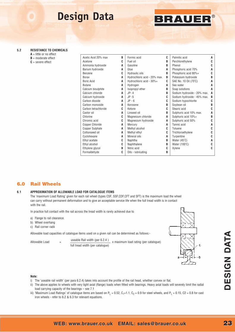
6.1 APPROXIMATION OF ALLOWABLE LOAD FOR CATALOGUE ITEMSThe ‘maximum Load Rating’ given for each rail wheel (types CSF, SSF,CDF,CFT and SFT) is the maximum load the wheelcan carry without permanent deformation and to give an acceptable service life when the full tread width is in contactwith the rail.
In practice full contact with the rail across the tread width is rarely achieved due to
a) Flange to rail clearance.b) Wheel overhangc) Rail corner radii
Allowable load capacities of catalogue items used on a given rail can be determined as follows:-
Allowable Load =useable Rail width (per 6.2.4 )
x maximum load rating (per catalogue)full tread width (per catalogue)
Note:i) The ‘useable rail width’ (per para 6.2.4) takes into account the profile of the rail head, whether convex or flat.ii) The above applies to wheels with very light axial (flange) loads when fitted with bearings. Heavy axial loads will severely limit the radial
load carrying capacity of the bearings – see 7.1iii) ‘Maximum Load Ratings’ of catalogue items are based on PL = 0.52, C1=1.1, C2 = 0.9 for steel wheels, and PL = 0.15, C2 = 0.8 for cast
iron wheels - refer to 6.2 & 6.3 for relevant equations.
Acetic Acid 20% max BAcetone CAmmonia hydroxide ABarium hydroxide ABenzene CBorax ABoric Acid AButane ACalcium bisulphite A Calcium chloride ACalcium hydroxide ACarbon dioxide ACarbon monoxide ACarbon tetrachloride CCastor oil AChlorine CChromic acid CCopper Chloride ACopper Sulphate ACottonseed oil ACyclohexane AEthyl acetate CEthyl alcohol CEthylene glycol BFormaldehyde C
Formic acid CFuel oil BGasoline BGlue AHydraulic oils BHydrochloric acid - 20% max. BHydrochloric acid - 30%+ CHydrogen AIsopropyl ether BJP- 4 BJP -5 CJP - 6 CKerosene BKetone CLinseed oil B Magnesium chloride AMagnesium hydroxide AMercury AMethyl alcohol CMethyl ethyl CMineral oils ANaphtha BNaphthalene BNitric acid COils - lubricating B
Palmitic acid APerchlorethylene CPhenol CPhosphoric acid 70% APhosphoric acid 80%+ CPotassium hydroxide BSAE No. 10 Oil (70˚C) ASea water ASoap solutions ASodium hydroxide - 20% max. ASodium hydroxide - 45% max. BSodium hypochlorite C Soybean oil BStearic acid CSulphuric acid 10% max. ASulphuric acid 10%+ BSulphuric acid 50% CTannic acid AToluene CTrichloroethylene CTurpentine CWater (45˚C) AWater (100˚C) CXylene C
6.2 CALCULATION OF ALLOWABLE LOAD - STEEL OR S.G IRON RAIL WHEELSThe following equations can be used for wheels of up to 1.25m diameter of cast, rolled or forged steel, or S.G cast iron, to determine therelationship between:
i) wheel diameter ii) ultimate strength of wheel materialiii) load capacityiv) service lifev) the useable width of the railvi) speed of rotation of the wheel.
a) for the wheel to withstand the maximum static load to which it is subjected:
PL ≥ PS mean = PS mean
b x D x C1 max. x C2 max. b x D x 1.38
and
b) For the wheel to perform its specified duty without abnormal wear:
PL ≥ Pd mean
b x D x C1 x C2
Where: D = wheel diameter (mm)b = useable rail width (mm) – see 6.2.4PL = limiting pressure (kgf/mm2) – see 6.2.1C1 = a coefficient determined by r.p.m. – see 6.2.2C1 max. = 1.2C2 = a coefficient determined by ‘machine life and utilisation’ – see 6.2.3C2 max. = 1.15PS mean = the mean static load to be withstood by the wheel (kg)
= 2Ps max. + Ps min.
3Pd mean = the mean dynamic load to be withstood by the wheel (kg)
= 2Pd max. + Pd min.
3
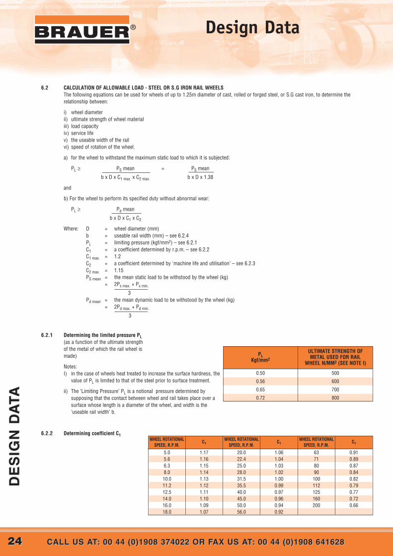
6.2.1 Determining the limited pressure PL(as a function of the ultimate strengthof the metal of which the rail wheel ismade)
Notes: I) in the case of wheels heat treated to increase the surface hardness, the
value of PL is limited to that of the steel prior to surface treatment.
ii) The ‘Limiting Pressure’ PL is a notional pressure determined bysupposing that the contact between wheel and rail takes place over asurface whose length is a diameter of the wheel, and width is the‘useable rail width’ b.
6.2.2 Determining coefficient C1
ULTIMATE STRENGTH OFMETAL USED FOR RAIL
WHEEL N/MM2 (SEE NOTE I)
PLKgf/mm2
0.50
0.56
0.65
0.72
500
600
700
800
5.05.66.38.0
10.011.212.514.016.018.0
WHEEL ROTATIONALSPEED, R.P.M.
C1WHEEL ROTATIONAL
SPEED, R.P.M.C1
WHEEL ROTATIONALSPEED, R.P.M.
C1
1.171.161.151.141.131.121.111.101.091.07
20.022.425.028.031.535.540.045.050.056.0
1.061.041.031.021.000.990.970.960.940.92
63718090
100112125160200
0.910.890.870.840.820.790.770.720.66
2424 CALL US AT: 00 44 (0)1908 374022 OR FAX US AT: 00 44 (0)1908 641628CALL US AT: 00 44 (0)1908 374022 OR FAX US AT: 00 44 (0)1908 641628
DE
SIG
N D
ATA
DE
SIG
N D
ATA
® Design Data

2525WEB: www.brauer.co.uk EMAIL: [email protected]: www.brauer.co.uk EMAIL: [email protected]
DE
SIG
N D
ATA
DE
SIG
N D
ATA
®Design Data
X BS 20 ’M’X BS 30 ’M’BS 35 ’M’BS 35 ’R’X BSC 40ACSE 40
X BS 50 ’O’BS 60 ‘R’
X BS 60 ’A’BS 70 ‘A’BS 75’R’BS 75’A’BS 80 ’O’BS 80 ‘R’BS 80 ’A’BS 90 ‘R’BS 90 ’A’BS 95 ‘A’BS 95 ’N’
BS 113 ‘A’
RAILSECTIONIDENTITY
RAIL TYPE
FLAT BOTTOM RAILS British
European
European
kg/m
SECTION WEIGHT
lb/yd HEIGHT A BASE BHEAD
WIDTH CWEB D RADIUS r
USABLEWIDTHb (mm)
PRINCIPAL DIMENSIONS (mm)
9.88114.78517.38717.36019.89020.09
24.83329.82230.61834.80737.04137.45539.78139.67439.76144.50645.09947.14246.95156.398
2030353540
40.550606070757580808090909595
113
65.0975.4180.9685.7388.1188.9
100.01114.30114.30123.82128.59128.59127.00133.35133.35142.88142.88147.64147.64158.75
55.5669.8576.2082.5580.5788.9
100.01109.54109.54111.12122.24114.30127.00127.00117.47136.53127.00141.29139.70139.70
30.9638.1042.8644.4545.6442.6052.3957.1557.1560.3261.9161.9163.5063.5063.5066.6766.6768.2669.8569.85
6.769.139.138.33
12.309.9
10.3211.1111.1112.3013.1012.7013.8913.4913.1013.8913.8914.2913.8920.00
6.357.927.927.929.137.948.739.539.539.53
11.1111.119.5311.1111.1112.7012.7012.7012.7012.70
22.4927.5432.3033.8933.4732.0240.7544.4444.4447.6147.1047.1050.7948.6948.6949.7449.7451.3352.9252.92
X BSC 13X BSC 16X BSC 20X BSC 28X BSC 35X BSC 50
S10S14S18S20S30
S41-10S49
UIC 54UIC 60
13.30616.02919.86128.62435.37550.179
26.7732.2539.9557.5871.16
100.00
48.054.055.567.076.076.0
92.0108.0127.0152.0160.0165.0
36.0044.5050.0050.0058.0058.50
––––––
11.0010.509.539.00
10.0010.00
14.0023.5030.9432.0038.0038.50
1014
18.319.8
30.0341.3849.3
54.4360.34
–––––––––
708093100108138149159172
58708282
108125125140150
32.0038.0043.0044.0060.3067.0067.0070.0072.00
69
1010
12.312.00
1416
16.5
6.008.008.009.008.00
–13.0013.00
–
24.0027.3332.3332.0049.63
–52.6754.67
–
BRIDGE RAILS British
X BSC 56X BSC 89
X BSC 101X BSC 164
58.80689.81
100.383166.83
114.27180.67201.94335.61
101.5114.0155.0150.0
171.0178.0165.0230.0
76.00102.00100.00140.00
––––
9.5310.0010.0010.00
56.9482.0080.00120.00
A45A55A65A75
A100A120A150
22.131.843.156.274.3100
150.3
–––––––
5565758595
105150
125150175200200220220
45.0055.00
6575100120150
24313845607280
4.005.00
68
1010–
37.0045.0053.0059.0080.00
100.00–
CRANE RAILS British
ITEMS SHOWN IN BOLD ARE NORMALLY AVAILABLE FOR NEW BUILD
6.2.3 Determining coefficient C2(machine life and utilisation)
Should a longer service life berequired for a given materialwhose load/life propertieshave been determined perparagraph 6.2 refer toparagraph 6.4 ‘SurfaceHardening’.
6.2.4 Determining the useable rail width, bThe useable rail width is determined by the following equations:
i) for convex topped rails b (mm) = C – 4 r ii) for flat topped rails b (mm) = C – 2r(these are generally flat bottom rails) 3 (these are generally bridge, crane and barstock rails)
Dimensions and Useable Widths of a selection of rails are given below. These are for illustration only and details may deviate. Brauerrecommend consulting the rail supplier for detailed cross section of rail selected before finalising the design of the wheel tread.
NOTE: Items with X are not manufactured by steel mills now.Items in bold are at time of printing still currently manufactured.
Mechanisms subjected very rarely to theirmaximum load and, normally, to very lightloads
1.12 1.12 1.12 1.12 1.12 1.00 0.90 0.80
Mechanisms occasionally subjected to theirmaximum load, but, normally, to ratherlighter loads
1.12 1.12 1.12 1.12 1.00 0.90 0.80 0.80
Mechanisms frequently subjected to theirmaximum load and, normally, to loads ofmedium magnitude
1.12 1.12 1.12 1.00 0.90 0.80 0.80 0.80
Mechanisms frequently or constantlysubjected to their maximum load 1.12 1.12 1.00 0.90 0.80 0.80 0.80 0.80
UTILISATIONSERVICE LIFE – HOURS
400 800 1600 3200 6300 12000 25000 50000

Where:tu = tensile strength of the wheel material (N/mm2)
tf = Flange thickness (mm)N = Flange safety factor (2.0 minimumrecommended)Km = load factor = 1.0 for gradually applied loads
= 1.5 for suddenly applied loadsKc = casting factor (for cast wheels only) = 1.5e = dimension (mm) from tread to point of
application of load P as shown;
2626 CALL US AT: 00 44 (0)1908 374022 OR FAX US AT: 00 44 (0)1908 641628CALL US AT: 00 44 (0)1908 374022 OR FAX US AT: 00 44 (0)1908 641628
DE
SIG
N D
ATA
DE
SIG
N D
ATA
® Design Data
6.3 CALCULATION OF ALLOWABLE LOAD - CAST IRON RAIL WHEELSWhile grey cast iron wheels are the most economic for light to medium duty, they are not suitable for high rotational speeds or where substantial shockloadings are to be withstood. Their performance is not as predictable as that of steel or S.G. iron wheels due principally to the presence of flake graphitewhich encourages ‘spalling’ of the surface.
6.3.1 Allowable Load - grey iron as castThe relationship between: Where:- D = wheel diameter (mm)
i) Wheel diameter b = useable rail width (mm) – see 6.2.4ii) Load capacity PL = 0.15 (a conservative value to provide an acceptable service life)iii) Useable rail width C2 max = 0.8
but not service life, can be approximated by the equation PL = Pmax Pmax = maximum load to be withstood by the wheel (kg)
b x D x C2 max
6.3.2 Allowable Load - chilled cast iron or surface hardened cast ironChilling or surface hardening of cast iron refines and hardens the surface to give an economic wheel capable of carrying moderate loads, with aservice life similar to that of comparable steel wheels. For cast iron wheels having a hardened surface, the equation for steels wheels applies (para6.2) with a value PL = 0.50
6.4 SURFACE HARDENINGSurface hardening can extend service life beyond that given in para 6.2.3. a guide to the relationship betweensurface hardness and service life being:
Note: The surface hardness of the wheel must be taken into account when selecting the rail.
6.5. FLANGE STRENGTHAn approximation of rail wheel flange strength sufficient for most purposes can be determined as follows:
Allowable flange bending moment M (Nmm) = tu x 1.5 x tf3
6 x N x Km x Kc
Allowable flange load due to bending P (kg) = M
9.81 x e
Note: Moments about bearings and axial loads on bearings due toflange loads must be taken into account when selecting bearingsand axle/bearing arrangements -see 7.1
7.0 Bearing and Seal Arrangements – Non Standard Wheels7.1 SELECTION OF BEARINGS
The main considerations in theselection of bearings are:
i) radial load
ii) axial load
iii) speed of rotation
iv) bearing friction
In selecting ball or roller bearings it isimportant that the static and/ordynamic radial load rating requirementfor each bearing should be determinedtaking into account a) the radial load.b) the radial equivalent or anyaxial load (as given in the bearingmanufacturer’s catalogue), and c) theradial load resulting from the momentof the axial load acting about thebearings.
It should be noted that in most bearingarrangements axial loads are taken byonly one bearing , and that loadscaused by condition c) above usuallyact positively on one bearing (beingadded to the radial load) and negativelyon the other bearing (being deductedfrom the radial load).
1. Plain bronze or self-lubricating bushing
Very High
Very Light Low Moderate/
High
DESCRIPTION GENERALARRANGEMENT
RADIAL LOAD AXIAL LOAD SPEED OFROTATION
BEARINGFRICTION
2. Flanged bronze or self-lubricating bushing
Very High High Low Moderate/
High
3. Ball bearings Light/Moderate Light High Low
4. Opposed taper rollerbearings Moderate Moderate High Low
5. Spherical roller bearings High Light/Moderate High Low
6. Spherical roller orcylindrical roller bearingsand thrust washers orthrust bearings
High Very High High Low
7. Needle roller bearings andthrust washers or thrustbearings
Very High
Very High High Low
240280320360400
1.01.72.02.22.3
SURFACEHARDNESS (Hv)
LIFE FACTOR(240 HV = 1)
2727WEB: www.brauer.co.uk EMAIL: [email protected]: www.brauer.co.uk EMAIL: [email protected]
DE
SIG
N D
ATA
DE
SIG
N D
ATA
®Design Data
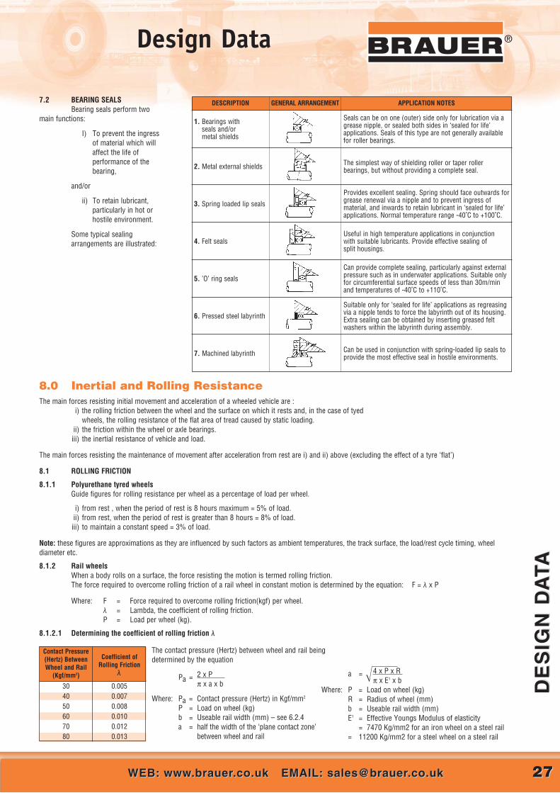
1. Bearings withseals and/ormetal shields
Seals can be on one (outer) side only for lubrication via agrease nipple, or sealed both sides in ‘sealed for life’applications. Seals of this type are not generally availablefor roller bearings.
The simplest way of shielding roller or taper rollerbearings, but without providing a complete seal.
Provides excellent sealing. Spring should face outwards forgrease renewal via a nipple and to prevent ingress ofmaterial, and inwards to retain lubricant in ‘sealed for life’applications. Normal temperature range -40˚C to +100˚C.
Useful in high temperature applications in conjunctionwith suitable lubricants. Provide effective sealing ofsplit housings.
Can provide complete sealing, particularly against externalpressure such as in underwater applications. Suitable onlyfor circumferential surface speeds of less than 30m/minand temperatures of -40˚C to +110˚C.
Suitable only for ‘sealed for life’ applications as regreasingvia a nipple tends to force the labyrinth out of its housing.Extra sealing can be obtained by inserting greased feltwashers within the labyrinth during assembly.
Can be used in conjunction with spring-loaded lip seals toprovide the most effective seal in hostile environments.
DESCRIPTION GENERAL ARRANGEMENT APPLICATION NOTES
2. Metal external shields
3. Spring loaded lip seals
4. Felt seals
5. ’O’ ring seals
6. Pressed steel labyrinth
7. Machined labyrinth
7.2 BEARING SEALSBearing seals perform two
main functions:
I) To prevent the ingressof material which willaffect the life ofperformance of thebearing,
and/or
ii) To retain lubricant,particularly in hot orhostile environment.
Some typical sealingarrangements are illustrated:
8.0 Inertial and Rolling ResistanceThe main forces resisting initial movement and acceleration of a wheeled vehicle are :
i) the rolling friction between the wheel and the surface on which it rests and, in the case of tyedwheels, the rolling resistance of the flat area of tread caused by static loading.
ii) the friction within the wheel or axle bearings.iii) the inertial resistance of vehicle and load.
The main forces resisting the maintenance of movement after acceleration from rest are i) and ii) above (excluding the effect of a tyre ‘flat’)
8.1 ROLLING FRICTION
8.1.1 Polyurethane tyred wheelsGuide figures for rolling resistance per wheel as a percentage of load per wheel.
i) from rest , when the period of rest is 8 hours maximum = 5% of load.ii) from rest, when the period of rest is greater than 8 hours = 8% of load.iii) to maintain a constant speed = 3% of load.
Note: these figures are approximations as they are influenced by such factors as ambient temperatures, the track surface, the load/rest cycle timing, wheeldiameter etc.
8.1.2 Rail wheels When a body rolls on a surface, the force resisting the motion is termed rolling friction.The force required to overcome rolling friction of a rail wheel in constant motion is determined by the equation: F = λ x P
Where: F = Force required to overcome rolling friction(kgf) per wheel.λ = Lambda, the coefficient of rolling friction.P = Load per wheel (kg).
8.1.2.1 Determining the coefficient of rolling friction λ
304050607080
Contact Pressure(Hertz) BetweenWheel and Rail
(Kgf/mm2)
Coefficient ofRolling Friction
λ
0.0050.0070.0080.0100.0120.013
a = ����4 x P x R π x E1 x b
Where: P = Load on wheel (kg)R = Radius of wheel (mm)b = Useable rail width (mm)E1 = Effective Youngs Modulus of elasticity
= 7470 Kg/mm2 for an iron wheel on a steel rail= 11200 Kg/mm2 for a steel wheel on a steel rail
The contact pressure (Hertz) between wheel and rail beingdetermined by the equation
Pa = 2 x P π x a x b
Where: Pa = Contact pressure (Hertz) in Kgf/mm2
P = Load on wheel (kg)b = Useable rail width (mm) – see 6.2.4a = half the width of the ‘plane contact zone’
between wheel and rail

2828 CALL US AT: 00 44 (0)1908 374022 OR FAX US AT: 00 44 (0)1908 641628CALL US AT: 00 44 (0)1908 374022 OR FAX US AT: 00 44 (0)1908 641628
DE
SIG
N D
ATA
DE
SIG
N D
ATA
® Design Data
8.2 BEARING FRICTIONFor the purpose of determining the force required to start or maintain a wheel in motion the frictional resistance of ball or roller bearings, with theircoefficient in the region of 0.002, can be disregarded.
The force required to overcome bearing friction for plain bearings is determined by the equation: F = µ x P x d
DWhere: F = force required to overcome bearing friction(kg)
µ = The coefficient of frictionP = load on wheel (kg)d = diameter of axle (mm)D = diameter of wheel (mm)
The table gives guide figures for the coefficient of friction µ for rolling bearingsand for various plain bearing materials running on a smooth steel axle.
The lubricated coefficient should be used for wheels in motion, and theunlubricated coefficient for wheels starting from a period of rest under staticload (which assumes the worst condition)
8.3 INERTIAL RESISTANCE
To calculate the force required to accelerate the mass of the vehicle and its load from rest with a uniform rate of acceleration on a level track:
i) when the time taken to achieve the final velocity is known F = M x Vf
t x g
or, ii) when the distance taken to achieve the final velocity is known F = M x Vf2
2 x s x g
Where: F = force required to overcome inertia (kg)M = total mass of vehicle and load (kg)Vf = final velocity (m/sec)t = time taken to achieve final velocity from rest (secs)s = distance taken to achieve final velocity from rest (m)g = force of gravity = 9.81 m/sec2
9.0 Traction – Coefficient of FrictionThe traction of a driving wheel = µ x P
Where: µ = the coefficient of friction for a givenwheel material and track surface.
p = the load of the wheel.
Guides values for coefficients of friction µ, for wheel andtyre materials in contact with various surfaces are given:
10.0 Load Calculations For Wheels Supporting and/or Driving Rotating Drums.
In installations where support wheels drive the drum we recommend that the driving wheels be positioned on the upwardly rotating side of thedrum (as shown below) which is the more heavily laden side.
To determine the required ‘Maximum Load Rating’ for wheels at each support position for the purpose of wheel selection:
Maximum Load Rating – Drive Wheel =(0.5P1) + P2
Cos � x L x LS x LC
Maximum Load Rating – Idler Wheel 1 =0.5 (P1 + P2)
Cos � LS x LC
Maximum Load Rating – Idler Wheel 2 =(0.5P1) + P2
Cos � x LS x LC
Where: P1 = weight of the drum at the support position under consideration (kg)P2 = weight of the contents at the support position under consideration (kg)L = 0.7 = Load factor for driving wheels (polyurethane tyred wheels only)LS = Load factor according to drum surface speed – see 5.1 (polyurethane tyred wheels only)Lc = 0.75 = Load factor for continuous running - see 5.1 (polyurethane tyred wheels only)
Cast ironBronze
Thin wall PTFE/Lead wrapped bushes
Bearing MaterialCoefficient of Friction µ
Lubricated Unlubricated0.210.16
0.02 - 0.20
0.400.35
0.02 - 0.20
Dry SteelWet Steel
Dry Smooth ConcreteWet Smooth ConcreteDry Rough ConcreteWet Rough Concrete
Ice
SurfaceWheel or Tyre Material
Rubber Polyurethane0.80.50.80.51.00.90.1
0.70.40.70.60.80.60.1
Steel Cast Iron Nylon0.60.4––––
0.02
0.40.3––––
0.02
0.40.15
–––––
2929WEB: www.brauer.co.uk EMAIL: [email protected]: www.brauer.co.uk EMAIL: [email protected]
DE
SIG
N D
ATA
DE
SIG
N D
ATA
®Design Data
11.0 Keyway Dimensions – Parallel Key
Generally - (to commercial
tolerances – keyways to BS46:
part 1: 1958 and BS4235: part 1:
1972 available to order)
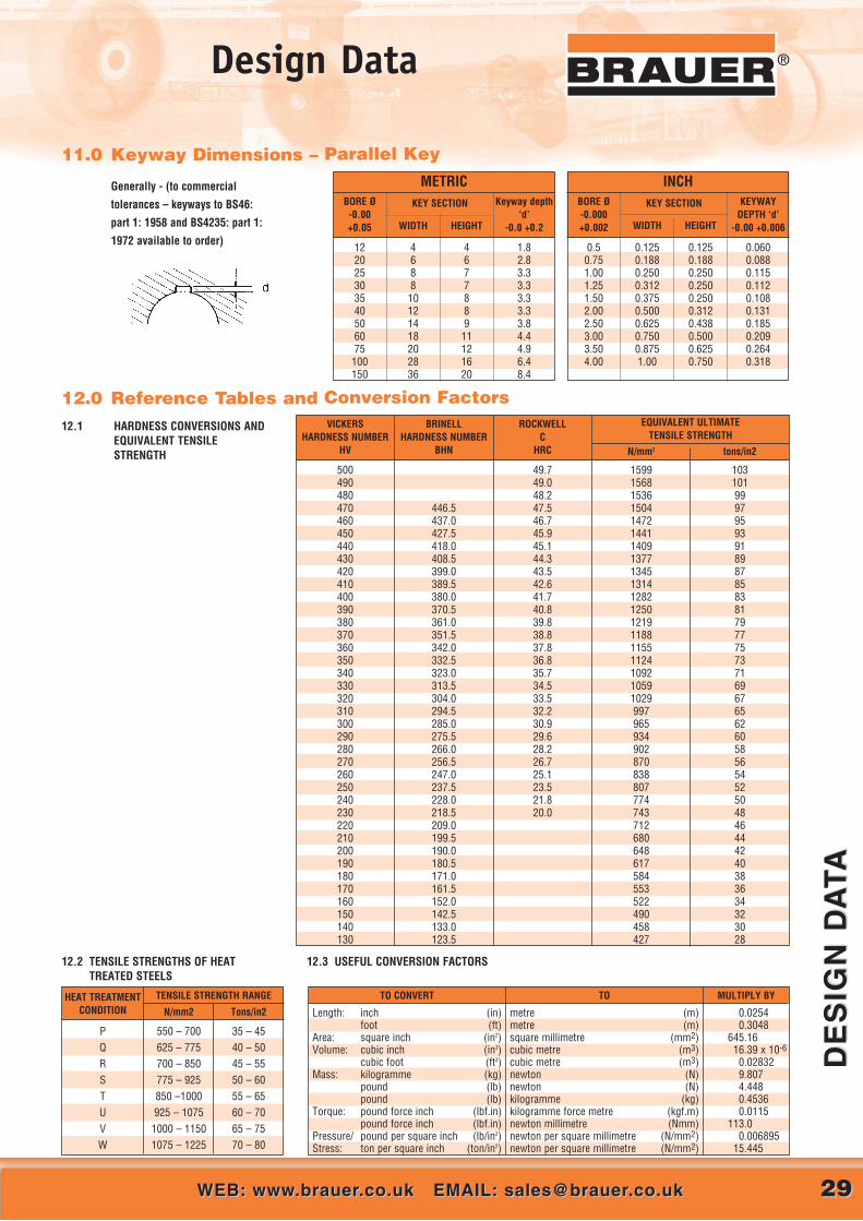
12.0 Reference Tables and Conversion Factors12.1 HARDNESS CONVERSIONS AND
EQUIVALENT TENSILESTRENGTH
12.2 TENSILE STRENGTHS OF HEAT 12.3 USEFUL CONVERSION FACTORSTREATED STEELS
PQRSTUVW
HEAT TREATMENTCONDITION
TENSILE STRENGTH RANGE
N/mm2 Tons/in2
550 – 700625 – 775700 – 850775 – 925850 –1000925 – 10751000 – 11501075 – 1225
35 – 4540 – 5045 – 5550 – 6055 – 6560 – 7065 – 7570 – 80
500490480470460450440430420410400390380370360350340330320310300290280270260250240230220210200190180170160150140130
VICKERSHARDNESS NUMBER
HV
BRINELLHARDNESS NUMBER
BHN
ROCKWELLC
HRC
EQUIVALENT ULTIMATE TENSILE STRENGTH
tons/in2N/mm2
446.5437.0427.5418.0408.5399.0389.5380.0370.5361.0351.5342.0332.5323.0313.5304.0294.5285.0275.5266.0256.5247.0237.5228.0218.5209.0199.5190.0180.5171.0161.5152.0142.5133.0123.5
49.749.048.247.546.745.945.144.343.542.641.740.839.838.837.836.835.734.533.532.230.929.628.226.725.123.521.820.0
1599156815361504147214411409137713451314128212501219118811551124109210591029997965934902870838807774743712680648617584553522490458427
103101999795939189878583817977757371696765626058565452504846444240383634323028
Length: inch (in)foot (ft)
Area: square inch (in2)Volume: cubic inch (in3)
cubic foot (ft3)Mass: kilogramme (kg)
pound (lb)pound (lb)
Torque: pound force inch (lbf.in)pound force inch (lbf.in)
Pressure/ pound per square inch (lb/in2)Stress: ton per square inch (ton/in2)
TO CONVERT TO MULTIPLY BY
metre (m)metre (m)square millimetre (mm2)cubic metre (m3)cubic metre (m3)newton (N)newton (N)kilogramme (kg)kilogramme force metre (kgf.m)newton millimetre (Nmm)newton per square millimetre (N/mm2)newton per square millimetre (N/mm2)
0.02540.3048
645.1616.39 x 10-6
0.028329.8074.4480.45360.0115
113.00.006895
15.445
0.50.751.001.251.502.002.503.003.504.00
0.1250.1880.2500.3120.3750.5000.6250.7500.8751.00
0.1250.1880.2500.2500.2500.3120.4380.5000.6250.750
0.0600.0880.1150.1120.1080.1310.1850.2090.2640.318
INCHBORE Ø-0.000+0.002 WIDTH
KEY SECTION
HEIGHT
KEYWAYDEPTH ‘d’
-0.00 +0.006
122025303540506075
100150
4688
10121418202836
4677889
11121620
1.82.83.33.33.33.33.84.44.96.48.4
BORE Ø-0.00+0.05
METRIC
WIDTH
KEY SECTION
HEIGHT
Keyway depth‘d’
-0.0 +0.2
3030 CALL US AT: 00 44 (0)1908 374022 OR FAX US AT: 00 44 (0)1908 641628CALL US AT: 00 44 (0)1908 374022 OR FAX US AT: 00 44 (0)1908 641628
DE
SIG
N D
ATA
DE
SIG
N D
ATA
® Design Data
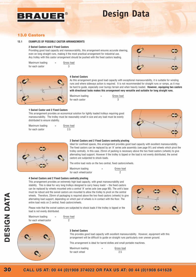
13.0 Castors13.1 EXAMPLES OF POSSIBLE CASTOR ARRANGEMENTS
2 Swivel Castors and 2 Fixed CastorsProviding good load capacity and manoeuvrability, this arrangement ensures accurate steering,even on long straight runs, making it the most practical arrangement for industrial use.Any trolley with this castor arrangement should be pushed with the fixed castors leading.
Maximum loading = Gross loadfor each castor 3
4 Swivel CastorsAs this arrangement gives good load capacity with exceptional manoeuvrability, it is suitable for windingruns and where sideways action is required. It is not recommended for straight runs or ramps, as it maybe hard to guide, especially over bumpy terrain and when heavily loaded. However, equipping two castorswith directional locks makes this arrangement very versatile and suitable for long straight runs.
Maximum loading = Gross loadfor each castor 3
1 Swivel Castor and 2 Fixed CastorsThis arrangement provides an economical solution for lightly loaded trolleys requiring goodmanoeuvrability. The trolley must be reasonably small in size and any load must be evenlydistributed to ensure stability.
Maximum loading = Gross loadfor each castor 2.5
2 Swivel Castors and 2 Fixed Castors centrally pivotingIdeal for confined spaces, this arrangement provides good load capacity with excellent manoeuvrability.The fixed castors can be replaced by an ‘A’ series axle assembly (see page 91) and wheels which pivot thetrolley centrally. In this case, 25mm of packing is necessary above the two fixed castors (wheels) to givealternating load support. However if the trolley is tipped or the load is not evenly distributed, the swivelcastors are subjected to shock loads.
The entire load rests on the two central, fixed castors/wheels.
Maximum loading = Gross loadfor each wheel/castor 2
4 Swivel Castors and 2 Fixed Castors centrally pivotingThis arrangement provides an extremely high load capacity, with great manoeuvrability andstability. This is ideal for very long trolleys designed to carry heavy loads’ – the fixed castorscan be replaced by wheels mounted onto a central ‘A’ series axle (see page 90). The unit’s basemust be robust and the swivel castors are mounted to allow the trolley to pivot on the centralwheels. Therefore, 25mm of packaging is required above the two fixed castors (wheels) to givealternating load support, depending on which pair of wheels is in contact with the floor. Theentire load rests on 2 central, fixed castors/wheels.
Please note that the swivel castors are subjected to shock loads if the trolley is tipped or theload is not evenly distributed.
Maximum loading = Gross loadfor each wheel/castor 2
3 Swivel CastorsThis provides good load capacity with excellent manoeuvrability. However, equipment with thisarrangement will be difficult to guide on straight runs particularly over uneven ground.
This arrangement is ideal for barrel dollies and small portable machines.
Maximum loading = Gross loadfor each wheel 2.5
RC
C1
R1
C2R2C
R
C
R R 1
CR
CR1 R

2 Fixed Castors and 2 Fixed Castorscentrally pivoting.Suitable for moderate loads and long, straightruns with occasional changes in direction.The two central fixed castors can be replacedby wheels mounted onto a central ‘A’ seriesaxle (see page 90). The two end castors aremounted as to pivot the trolley centrally.25mm of packing is necessary above the two central castors (wheels) to give alternating load support. However if the trolley is tipped or the loadis not evenly distributed, the end castors are subject to shock loads. The entire load rests on the 2 central, fixed castors/wheels.
Maximum loading for = Gross load each wheel/castor 2
13.1.2 Correct alignment of castorsi) Fixed and directional lock swivel castors - the mounting holes in the top plates are clearance holes and it is essential to align the castors
correctly before the bolts are finally tightened.ii) Swivel castors - it is essential they are mounted with the swivel axis vertical
13.1.3 Important Note The formulae above for the maximum loading for each castor is for an equally distributed load.
13.2 LOAD RATING
13.2.1 Limitations to stated maximum load rating for each model number:-a) Untyred wheels - refer to design data para 2.0b) rubber tyred wheels - refer to design data para 3.0c) Polyurethane tyred wheels - refer to design data para 5.0
13.2.2 Floor conditionsThe stated maximum load rating for each model assumes that the floor is reasonably level and free from cracks, obstructions, guide rails ,gullies etc.
If any of the above are present in the operating environment then a castor with a load rating several times grater than calculated must be used.In addition the wheel diameter must be large enough to easily pass over any cracks, ridges and other obstructions.
13.3 MANUAL PROPULSIONThe generally accepted effort an average human is capable of exerting is:-a) 18 Kgf for moving from a standing startb) 12 Kgf for a short distance once in motionc) 6 Kgf for longer distances on travel
For inertial and rolling resistance, refer to design data para 8.0 and for traction design data para 9.0
13.4 POWER TOWINGObstructions such as kerbs and gullies and even relatively small steps, can exert enormous impact loads which can damage a castor. Steps such aslift sills, drains covers and joints in concrete slabs, present a particular problem if they are not approached squarely and at low speeds. Approachingsuch obstacles obliquely makes the castor turn at right angles to the obstruction instead of turning in such a way that it can climb over it, thisdamages the castor.
Towing trailers in train increases the problem as only one castor may have to withstand the force generated by the mass of the whole trainincluding the tractor.
When towing trailers in train the diagram below illustrates the position of the pin couplings relative to the rear fixed castors to ensure theweight of the trailer and its contents are evenly distributed between the front swivel castors and rear fixed castors as well as ensuring goodtracking.
W W/ 2 W /2
3 / 4L 1 / 4L
Direction ofmovement
Front swivel castors Rear fixed castors
“ “
L
3131WEB: www.brauer.co.uk EMAIL: [email protected]: www.brauer.co.uk EMAIL: [email protected]
DE
SIG
N D
ATA
DE
SIG
N D
ATA
®Design Data
C
R

Wheel and Axle Assemblies
3232 CALL US AT: 00 44 (0)1908 374022 OR FAX US AT: 00 44 (0)1908 641628CALL US AT: 00 44 (0)1908 374022 OR FAX US AT: 00 44 (0)1908 641628
WH
EE
LS
AN
D A
XL
E A
SS
EM
BL
IES
WH
EE
LS
AN
D A
XL
E A
SS
EM
BL
IES
®®®
Wheel Type (Series)
Wheel Diameter (mm)
Tread Width (mm)
Bearing Type see opposite
Bore: M = Metric, I = Inch
Bore Diameter
SSF 400 / 70 / TB M 60 BEARING TYPESBJ = Ball Journal TB = Taper Roller CRB = Cylindrical Roller SPHBR = Spherical Roller PB = Plain bore K = Keyway SL = Self lubricating bush
Part Numbering Brauer wheels have descriptive part numbers as shown by the following example:
Non-catalogue items use the same descriptive part numbering system prefixed by the word specified, abbreviated as “spec”.

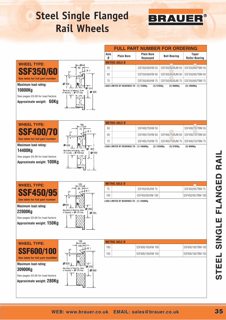
Steel Single FlangedRail Wheels
3333WEB: www.brauer.co.uk EMAIL: [email protected]: www.brauer.co.uk EMAIL: [email protected]
ST
EE
L S
ING
LE
FL
AN
GE
D R
AIL
ST
EE
L S
ING
LE
FL
AN
GE
D R
AIL
®®®
METRIC AXLE Ø
MATERIAL: Steel to BS970: Part I: 1983: 080M40
OPERATING TEMPERATURE RANGE:Plain bored or keywayed wheels – 30˚C to 350˚CBall or taper roller bearinged wheels – 40˚C to 120˚C
The ‘maximum load rating’ given for each wheel is based on the full treadwidth being in contact with the rail. Working loads must be calculated basedon the useable rail width and operating conditions – see ‘Design Data’ paras.6.1. and 6.2.
Standard wheel features a 3˚ tread angle to assist centering of pairs of wheelson common axles when used with convex crown rails. When single flangedwheels are to be used singly or on flat topped rails, ‘flat treads’, (which havethe tread parallel to the wheel axis and flanges at a 5˚angle) should bespecified by adding suffix ‘FT’ to the part number. (Tread diameter may bereduced)
Alternative bore/bearing diameters and alternative bearing types (i.e. bronzebushes, self-lubricating bushes, roller bearings, spherical roller bearings,etc.) are available to order – see pages 26-27.
Plain bore wheels are not drilled and tapped for greasing unless requestedat time of order.
For technical information covering load factors, inertial and rollingresistance, coefficients of friction between wheel and track, and keywaydimensions, see “Design Data” Index on page 20.
FULL PART NUMBER FOR ORDERING
WHEEL TYPE:
SSF75/25See table for full part number
AxleØ
Plain BorePlain Bore Keywayed
Ball BearingTaper
Roller Bearing
20
25
SSF75/25/KM 20
SSF75/25/KM 25
SSF75/25/BJM 20
SSF75/25/BJM 25
SSF75/25/TBM 20
SSF75/25/TBM 25
Maximum load rating:
975KgSee pages 23-26 for load factors
Approximate weight: 1.4Kg
Wheels fitted with ball journals are pre-lubricated, double shielded
LOAD LIMITED BY BEARINGS TO: (1) 900Kg
• TBM25 is actually Ø52mm recess, but considered acceptable
• Too small for grease nipples
(1)
METRIC AXLE ØWHEEL TYPE:
SSF100/25See table for full part number
20
25
SSF100/25/KM 20
SSF100/25/KM 25
SSF100/25/BJM 20
SSF100/25/BJM 25
SSF100/25/TBM 20
SSF100/25/TBM 25
Maximum load rating:
1300KgSee pages 23-26 for load factors
Approximate weight: 2.5Kg
Wheels fitted with ball journals are pre-lubricated, double shielded
LOAD LIMITED BY BEARINGS TO: (1) 900Kg (2) 1140Kg
• Too small for grease nipples
(2)
(1)

Steel Single FlangedRail Wheels
3434 CALL US AT: 00 44 (0)1908 374022 OR FAX US AT: 00 44 (0)1908 641628CALL US AT: 00 44 (0)1908 374022 OR FAX US AT: 00 44 (0)1908 641628
ST
EE
L S
ING
LE
FL
AN
GE
D R
AIL
ST
EE
L S
ING
LE
FL
AN
GE
D R
AIL
®®®
METRIC AXLE Ø
METRIC AXLE Ø
WHEEL TYPE:
SSF250/55See table for full part number
35
40
50
SSF250/55/KM 35
SSF250/55/KM 40
SSF250/55/KM 50
SSF250/55/BJM 35
SSF250/55/BJM 40
SSF250/55/BJM 50
SSF250/55/TBM 35
SSF250/55/TBM 40
SSF250/55/TBM 50Maximum load rating:
7100KgSee pages 23-26 for load factors
Approximate weight: 29Kg
LOAD LIMITED BY BEARINGS TO: (1) 2800Kg (2) 3384Kg (4) 6625Kg
METRIC AXLE Ø
(2)
(1) (4)
WHEEL TYPE:
SSF300/60See table for full part number
40
50
SSF300/60/KM 40
SSF300/60/KM 50
SSF300/60/BJM 40
SSF300/60/BJM 50
SSF300/60/TBM 40
SSF300/60/TBM 50
Maximum load rating:
9300kgSee pages 23-26 for load factors
Approximate weight: 45Kg
LOAD LIMITED BY BEARINGS TO: (1) 4400Kg (2) 7340Kg (3) 8155Kg
(2)
(1) (3)
FULL PART NUMBER FOR ORDERINGAxle
ØPlain Bore
Plain Bore Keywayed
Ball BearingTaper
Roller Bearing
METRIC AXLE ØWHEEL TYPE:
SSF200/55See table for full part number
Maximum load rating:
5700KgSee pages 23-26 for load factors
Approximate weight: 18Kg
LOAD LIMITED BY BEARINGS TO: (1) 2040Kg (2) 2800Kg (3) 3384Kg (4) 5200Kg
30
35
40
SSF200/55/KM 30
SSF200/55/KM 35
SSF200/55/KM 40
SSF200/55/BJM 30
SSF200/55/BJM 35
SSF200/55/BJM 40
SSF200/55/TBM 30
SSF200/55/TBM 35
SSF200/55/TBM 40
(1) (4)
(2)
(3)
METRIC AXLE ØWHEEL TYPE:
SSF150/40See table for full part number
25
30
35
SSF150/40/KM 25
SSF150/40/KM 30
SSF150/40/KM 35
SSF150/40/BJM 25
SSF150/40/BJM 30
SSF150/40/TBM 25
SSF150/40/TBM 30
Wheels fitted with ball journals are pre-lubricated, double shielded
Maximum load rating:
3100KgSee pages 23-26 for load factors
Approximate weight: 8.5Kg
LOAD LIMITED BY BEARINGS TO: (1) 1140Kg (2) 2040Kg
(1)
(2)
Steel Single FlangedRail Wheels
3535WEB: www.brauer.co.uk EMAIL: [email protected]: www.brauer.co.uk EMAIL: [email protected]
ST
EE
L S
ING
LE
FL
AN
GE
D R
AIL
ST
EE
L S
ING
LE
FL
AN
GE
D R
AIL
®®®
METRIC AXLE Ø
METRIC AXLE Ø
METRIC AXLE Ø
FULL PART NUMBER FOR ORDERINGAxle
ØPlain Bore
Plain Bore Keywayed
Ball BearingTaper
Roller Bearing
WHEEL TYPE:
SSF450/95See table for full part number
Maximum load rating:
22000KgSee pages 23-26 for load factors
Approximate weight: 150Kg
WHEEL TYPE:
SSF600/100See table for full part number
Maximum load rating:
30900KgSee pages 23-26 for load factors
Approximate weight: 280Kg
75
100
SSF450/95/KM 75
SSF450/95/KM 100
SSF450/95/TBM 75
SSF450/95/TBM 100
100
150
SSF600/100/KM 100
SSF600/100/KM 150
SSF600/100/TBM 100
SSF600/100/TBM 150
WHEEL TYPE:
SSF400/70See table for full part number
50
60
75
SSF400/70/KM 50
SSF400/70/KM 60
SSF400/70/KM 75
SSF400/70/BJM 60
SSF400/70/BJM 75
SSF400/70/TBM 50
SSF400/70/TBM 60
SSF400/70/TBM 75Maximum load rating:
14400KgSee pages 23-26 for load factors
Approximate weight: 100Kg
LOAD LIMITED BY BEARINGS TO: (1) 10600Kg (2) 13350Kg (3) 9785Kg (4) 9000Kg
(3)
(4)
(2)
(1)
(1)
METRIC AXLE ØWHEEL TYPE:
SSF350/60See table for full part number
50
60
75
SSF350/60/KM 50
SSF350/60/KM 60
SSF350/60/KM 75
SSF350/60/BJM 50
SSF350/60/BJM 60
SSF350/60/BJM 75
SSF350/60/TBM 50
SSF350/60/TBM 60
SSF350/60/TBM 75Maximum load rating:
10800KgSee pages 23-26 for load factors
Approximate weight: 60Kg
LOAD LIMITED BY BEARINGS TO: (1) 7340Kg (2) 9785Kg (3) 9000Kg (4) 10600Kg
(2)
(3)
(4) (1)
LOAD LIMITED BY BEARINGS TO: (1) 19400Kg

Cast Iron Single Flanged Rail Wheels
3636 CALL US AT: 00 44 (0)1908 374022 OR FAX US AT: 00 44 (0)1908 641628CALL US AT: 00 44 (0)1908 374022 OR FAX US AT: 00 44 (0)1908 641628
CA
ST
IR
ON
SIN
GL
E F
LA
NG
ED
RA
ILC
AS
T I
RO
N S
ING
LE
FL
AN
GE
D R
AIL
®®®
METRIC AXLE Ø
FULL PART NUMBER FOR ORDERINGAxle
ØPlain Bore
Plain Bore Keywayed
Ball BearingTaper
Roller Bearing
20
25
CSF63/25/PBM 20
CSF63/25/PBM 25
CSF63/25/KM 20
CSF63/25/KM 25
CSF63/25/BJM 20
Cast iron rail wheels are the most economic for light to medium duty, but theyhave a limited service life when compared to steel wheels, and are unsuitablefor high rotational speeds or where substantial shock loads are to bewithstood.
MATERIAL: Cast iron to BS1452: 1977: Grade 200
The ‘maximum load rating’ given for each wheel is based on the full treadwidth being in contact with the rail. Working loads must be calculated basedon the useable rail width and operating conditions – see ‘Design Data’ paras.5.1. and 5.3.
OPERATING TEMPERATURE RANGE:Plain bored or keywayed wheels – 30˚C to 250˚CBall or taper roller bearinged wheels – 30˚C to 120˚C
Standard wheel features a 3˚ tread angle to assist centering of pairs of wheelson common axles when used with convex crown rails. When single flangedwheels are to be used singly or on flat topped rails, ‘flat treads’, (which havethe tread parallel to the wheel axis and flanges at a 5˚ angle) should bespecified by adding suffix ‘FT’ to the part number. (Tread diameter may berequired)
Alternative bore/bearing diameters and alternative bearing types (i.e. bronzebushes, self-lubricating bushes, roller bearings, spherical roller bearings,etc.) are available to order – see pages 26-27.
For technical information covering load factors, inertial and rollingresistance, coefficients of friction between wheel and track, andkeyway dimensions, see “Design Data” Index on page 20.
METRIC AXLE ØWHEEL TYPE:
CSF75/25See table for full part number
20
25
30
CSF75/25/PBM 20
CSF75/25/PBM 25
CSF75/25/PBM 30
CSF75/25/KM 20
CSF75/25/KM 25
CSF75/25/KM 30
CSF75/25/BJM 20
CSF75/25/BJM 25
Maximum load rating:
250KgSee pages 23-26 for load factors
Approximate weight: 1.5Kg
Wheels fitted with ball journals are pre-lubricated, double shielded
WHEEL TYPE:
CSF63/25See table for full part number
Maximum load rating:
200KgSee pages 23-26 for load factors
Approximate weight: 1Kg
Wheels fitted with ball journals are pre-lubricated, double shielded
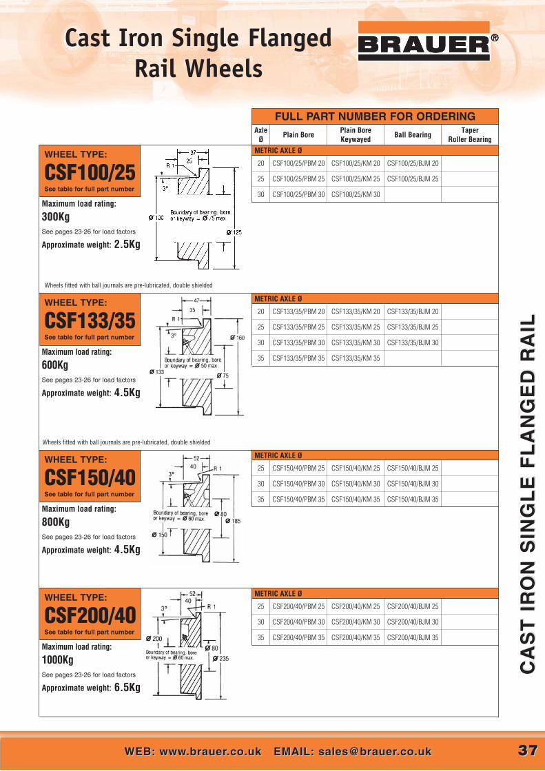
Cast Iron Single Flanged Rail Wheels
3737WEB: www.brauer.co.uk EMAIL: [email protected]: www.brauer.co.uk EMAIL: [email protected]
CA
ST
IR
ON
SIN
GL
E F
LA
NG
ED
RA
ILC
AS
T I
RO
N S
ING
LE
FL
AN
GE
D R
AIL
®®®
METRIC AXLE Ø
METRIC AXLE Ø
FULL PART NUMBER FOR ORDERING
WHEEL TYPE:
CSF150/40See table for full part number
WHEEL TYPE:
CSF200/40See table for full part number
AxleØ
Plain BorePlain Bore Keywayed
Ball BearingTaper
Roller Bearing
25
30
35
CSF150/40/PBM 25
CSF150/40/PBM 30
CSF150/40/PBM 35
CSF150/40/KM 25
CSF150/40/KM 30
CSF150/40/KM 35
CSF150/40/BJM 25
CSF150/40/BJM 30
CSF150/40/BJM 35
25
30
35
CSF200/40/PBM 25
CSF200/40/PBM 30
CSF200/40/PBM 35
CSF200/40/KM 25
CSF200/40/KM 30
CSF200/40/KM 35
CSF200/40/BJM 25
CSF200/40/BJM 30
CSF200/40/BJM 35
Maximum load rating:
800KgSee pages 23-26 for load factors
Approximate weight: 4.5Kg
Maximum load rating:
1000KgSee pages 23-26 for load factors
Approximate weight: 6.5Kg
METRIC AXLE ØWHEEL TYPE:
CSF133/35See table for full part number
20
25
30
35
CSF133/35/PBM 20
CSF133/35/PBM 25
CSF133/35/PBM 30
CSF133/35/PBM 35
CSF133/35/KM 20
CSF133/35/KM 25
CSF133/35/KM 30
CSF133/35/KM 35
CSF133/35/BJM 20
CSF133/35/BJM 25
CSF133/35/BJM 30Maximum load rating:
600KgSee pages 23-26 for load factors
Approximate weight: 4.5Kg
METRIC AXLE ØWHEEL TYPE:
CSF100/25See table for full part number
20
25
30
CSF100/25/PBM 20
CSF100/25/PBM 25
CSF100/25/PBM 30
CSF100/25/KM 20
CSF100/25/KM 25
CSF100/25/KM 30
CSF100/25/BJM 20
CSF100/25/BJM 25
Maximum load rating:
300KgSee pages 23-26 for load factors
Approximate weight: 2.5Kg
Wheels fitted with ball journals are pre-lubricated, double shielded
Wheels fitted with ball journals are pre-lubricated, double shielded
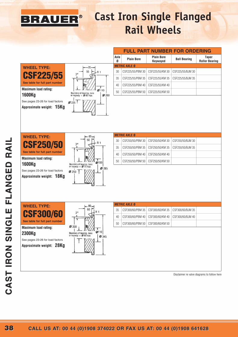
Cast Iron Single Flanged Rail Wheels
3838 CALL US AT: 00 44 (0)1908 374022 OR FAX US AT: 00 44 (0)1908 641628CALL US AT: 00 44 (0)1908 374022 OR FAX US AT: 00 44 (0)1908 641628
CA
ST
IR
ON
SIN
GL
E F
LA
NG
ED
RA
ILC
AS
T I
RO
N S
ING
LE
FL
AN
GE
D R
AIL
®®®
METRIC AXLE Ø
METRIC AXLE Ø
30
35
40
50
CSF250/50/PBM 30
CSF250/50/PBM 35
CSF250/50/PBM 40
CSF250/50/PBM 50
CSF250/50/KM 30
CSF250/50/KM 35
CSF250/50/KM 40
CSF250/50/KM 50
CSF250/50/BJM 30
CSF250/50/BJM 35
35
40
50
CSF300/60/PBM 35
CSF300/60/PBM 40
CSF300/60/PBM 50
CSF300/60/KM 35
CSF300/60/KM 40
CSF300/60/KM 50
CSF300/60/BJM 35
CSF300/60/BJM 40
WHEEL TYPE:
CSF250/50See table for full part number
Maximum load rating:
1600KgSee pages 23-26 for load factors
Approximate weight: 18Kg
WHEEL TYPE:
CSF300/60See table for full part number
Maximum load rating:
2300KgSee pages 23-26 for load factors
Approximate weight: 28Kg
FULL PART NUMBER FOR ORDERINGAxle
ØPlain Bore
Plain Bore Keywayed
Ball BearingTaper
Roller BearingMETRIC AXLE ØWHEEL TYPE:
CSF225/55See table for full part number
30
35
40
50
CSF225/55/PBM 30
CSF225/55/PBM 35
CSF225/55/PBM 40
CSF225/55/PBM 50
CSF225/55/KM 30
CSF225/55/KM 35
CSF225/55/KM 40
CSF225/55/KM 50
CSF225/55/BJM 30
CSF225/55/BJM 35
Maximum load rating:
1600KgSee pages 23-26 for load factors
Approximate weight: 15Kg
Disclaimer re valve diagrams to follow here
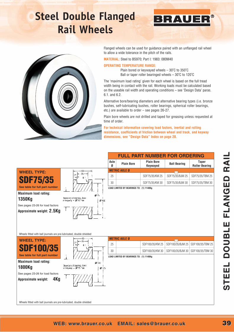
Steel Double Flanged Rail Wheels
3939WEB: www.brauer.co.uk EMAIL: [email protected]: www.brauer.co.uk EMAIL: [email protected]
ST
EE
L D
OU
BL
E F
LA
NG
ED
RA
ILS
TE
EL
DO
UB
LE
FL
AN
GE
D R
AIL
®®®
METRIC AXLE Ø
Flanged wheels can be used for guidance paired with an unflanged rail wheelto allow a wide tolerance in the pitch of the rails.
MATERIAL: Steel to BS970; Part I: 1983: 080M40
OPERATING TEMPERATURE RANGE:Plain bored or keywayed wheels – 30˚C to 350˚CBall or taper roller bearinged wheels – 30˚C to 120˚C
The ‘maximum load rating’ given for each wheel is based on the full treadwidth being in contact with the rail. Working loads must be calculated basedon the useable rail width and operating conditions – see ‘Design Data’ paras.6.1. and 6.2.
Alternative bore/bearing diameters and alternative bearing types (i.e. bronzebushes, self-lubricating bushes, roller bearings, spherical roller bearings,etc.) are available to order – see pages 26-27.
Plain bore wheels are not drilled and taped for greasing unless requested attime of order.
For technical information covering load factors, inertial and rollingresistance, coefficients of friction between wheel and track, and keywaydimensions, see “Design Data” Index on page 20.
FULL PART NUMBER FOR ORDERING
WHEEL TYPE:
SDF75/35See table for full part number
AxleØ
Plain BorePlain Bore Keywayed
Ball BearingTaper
Roller Bearing
Maximum load rating:
1350KgSee pages 23-26 for load factors
Approximate weight: 2.5Kg
25
30
SDF75/35/KM 25
SDF75/35/KM 30
SDF75/35/BJM 25
SDF75/35/BJM 30
SDF75/35/TBM 25
SDF75/35/TBM 30
LOAD LIMITED BY BEARINGS TO: (1) 1140Kg
Wheels fitted with ball journals are pre-lubricated, double shielded
(1)
METRIC AXLE ØWHEEL TYPE:
SDF100/35See table for full part number
Maximum load rating:
1800KgSee pages 23-26 for load factors
Approximate weight: 4Kg
25
30
SDF100/35/KM 25
SDF100/35/KM 30
SDF100/35/BJM 25
SDF100/35/BJM 30
SDF100/35/TBM 25
SDF100/35/TBM 30
LOAD LIMITED BY BEARINGS TO: (1) 1140Kg
Wheels fitted with ball journals are pre-lubricated, double shielded
(1)

Steel Double Flanged Rail Wheels
4040 CALL US AT: 00 44 (0)1908 374022 OR FAX US AT: 00 44 (0)1908 641628CALL US AT: 00 44 (0)1908 374022 OR FAX US AT: 00 44 (0)1908 641628
ST
EE
L D
OU
BL
E F
LA
NG
ED
RA
ILS
TE
EL
DO
UB
LE
FL
AN
GE
D R
AIL
®®®
METRIC AXLE Ø
METRIC AXLE Ø
WHEEL TYPE:
SDF225/50See table for full part number
FULL PART NUMBER FOR ORDERINGAxle
ØPlain Bore
Plain Bore Keywayed
Ball BearingTaper
Roller Bearing
Maximum load rating:
5800KgSee pages 23-26 for load factors
Approximate weight: 36Kg
50
60
SDF225/50/KM 50
SDF225/50/KM 60
SDF225/50/BJM 50
SDF225/50/BJM 60
SDF225/50/TBM 50
SDF225/50/TBM 60
WHEEL TYPE:
SDF225/60See table for full part number
Maximum load rating:
7000KgSee pages 23-26 for load factors
Approximate weight: 35Kg
50
60
SDF225/60/KM 50
SDF225/60/KM 60
SDF225/60/BJM 50
SDF225/60/BJM 60
SDF225/60/TBM 50
SDF225/60/TBM 60
METRIC AXLE ØWHEEL TYPE:
SDF200/50See table for full part number
Maximum load rating:
5100KgSee pages 23-26 for load factors
Approximate weight: 25kg
40
50
SDF200/50/KM 40
SDF200/50/KM 50
SDF200/50/BJM 40
SDF200/50/BJM 50
SDF200/50/TBM 40
SDF200/50/TBM 50
LOAD LIMITED BY BEARINGS TO: (1) 3384Kg
(1)
METRIC AXLE ØWHEEL TYPE:
SDF150/50See table for full part number
30
35
40
SDF150/50/KM 30
SDF150/50/KM 35
SDF150/50/KM 40
SDF150/50/BJM 30
SDF150/50/BJM 35
SDF150/50/BJM 40
SDF150/50/TBM 30
SDF150/50/TBM 35
SDF150/50/TBM 40Maximum load rating:
3900KgSee pages 23-26 for load factors
Approximate weight: 13Kg
(1)
(2)
(3)
LOAD LIMITED BY BEARINGS TO: (1) 2040Kg (2) 2800Kg (3) 3384Kg

Steel Double Flanged Rail Wheels
4141WEB: www.brauer.co.uk EMAIL: [email protected]: www.brauer.co.uk EMAIL: [email protected]
ST
EE
L D
OU
BL
E F
LA
NG
ED
RA
ILS
TE
EL
DO
UB
LE
FL
AN
GE
D R
AIL
®
METRIC AXLE Ø
FULL PART NUMBER FOR ORDERINGAxle
ØPlain Bore
Plain Bore Keywayed
Ball BearingTaper
Roller Bearing
WHEEL TYPE:
SDF350/60See table for full part number
Maximum load rating:
10800KgSee pages 23-26 for load factors
Approximate weight: 90Kg
50
60
75
SDF350/60/KM 50
SDF350/60/KM 60
SDF350/60/KM 75
SDF350/60/BJM 60
SDF350/60/BJM 75
SDF350/60/TBM 50
SDF350/60/TBM 60
SDF350/60/TBM 75
LOAD LIMITED BY BEARINGS TO: (1) 9785Kg (2) 9000Kg (3) 10600Kg
(3)
(1)
(2)
METRIC AXLE Ø
METRIC AXLE Ø
WHEEL TYPE:
SDF300/55See table for full part number
Maximum load rating:
8500KgSee pages 23-26 for load factors
Approximate weight: 60Kg
50
60
75
SDF300/55/KM 50
SDF300/55/KM 60
SDF300/55/KM 75
SDF300/55/BJM 50
SDF300/55/BJM 60
SDF300/55/BJM 75
SDF300/55/TBM 50
SDF300/55/TBM 60
SDF300/55/TBM 75
LOAD LIMITED BY BEARINGS TO: (1) 7340Kg
WHEEL TYPE:
SDF300/65See table for full part number
Maximum load rating:
10000KgSee pages 23-26 for load factors
Approximate weight: 59Kg
50
60
75
SDF300/65/KM 50
SDF300/65/KM 60
SDF300/65/KM 75
SDF300/65/BJM 60
SDF300/65/BJM 75
SDF300/65/TBM 50
SDF300/65/TBM 60
SDF300/55/TBM 75
LOAD LIMITED BY BEARINGS TO: (1) 9785Kg (2) 9000Kg
(1)
(1)
(2)
METRIC AXLE ØWHEEL TYPE:
SDF250/60See table for full part number
Maximum load rating:
7700KgSee pages 23-26 for load factors
Approximate weight: 44Kg
50
60
SDF250/60/KM 50
SDF250/60/KM 60
SDF250/60/BJM 50
SDF250/60/BJM 60
SDF250/60/TBM 50
SDF250/60/TBM 60
LOAD LIMITED BY BEARINGS TO: (1) 7340Kg
(1)

4242 CALL US AT: 00 44 (0)1908 374022 OR FAX US AT: 00 44 (0)1908 641628CALL US AT: 00 44 (0)1908 374022 OR FAX US AT: 00 44 (0)1908 641628
ST
EE
L D
OU
BL
E F
LA
NG
ED
RA
ILS
TE
EL
DO
UB
LE
FL
AN
GE
D R
AIL
® Steel Double Flanged Rail Wheels
FULL PART NUMBER FOR ORDERINGAxle
ØPlain Bore
Plain Bore Keywayed
Ball BearingTaper
Roller Bearing
METRIC AXLE ØWHEEL TYPE:
SDF600/100See table for full part number
Maximum load rating:
30900KgSee pages 23-26 for load factors
Approximate weight: 350Kg
100
150
SDF600/100/KM 100
SDF600/100/KM 150
SDF600/100/TBM 100
SDF600/100/TBM 150
METRIC AXLE ØWHEEL TYPE:
SDF450/80See table for full part number
Maximum load rating:
18500KgSee pages 23-26 for load factors
Approximate weight: 160Kg
75
100
SDF450/80/KM 75
SDF450/80/KM 100
SDF450/80/TBM 75
SDF450/80/TBM 100
METRIC AXLE ØWHEEL TYPE:
SDF450/70See table for full part number
Maximum load rating:
16200KgSee pages 23-26 for load factors
Approximate weight: 160Kg
75
100
SDF450/70/KM 75
SDF450/70/KM 100
SDF450/70/TBM 75
SDF450/70/TBM 100
METRIC AXLE ØWHEEL TYPE:
SDF350/75See table for full part number
Maximum load rating:
13500KgSee pages 23-26 for load factors
Approximate weight: 90Kg
60
75
100
SDF350/75/KM 60
SDF350/75/KM 75
SDF350/75/KM 100
SDF350/75/TBM 60
SDF350/75/TBM 75
SDF350/75/TBM 100
LOAD LIMITED BY BEARINGS TO: (1) 13350Kg
(1)

4343CALL US AT: 00 44 (0)1908 374022 OR FAX US AT: 00 44 (0)1908 641628CALL US AT: 00 44 (0)1908 374022 OR FAX US AT: 00 44 (0)1908 641628
CA
ST
IR
ON
DO
UB
LE
D F
LA
NG
ED
RA
ILC
AS
T I
RO
N D
OU
BL
ED
FL
AN
GE
D R
AIL
Cast Iron Double Flanged Rail Wheels
®
Cast iron rail wheels are the most economic for light to medium duty, but theyhave a limited service life when compared to steel wheels, and are unsuitablefor high rotational speeds or where substantial shock loads are to bewithstood.
Flanged wheels can be used for guidance paired with an unflanged rail wheelto allow a wide tolerance in the pitch of the rails.
MATERIAL: Cast iron to BS1452: 1977: Grade 200.
OPERATING TEMPERATURE RANGE:Plain bored or keywayed wheels – 30˚C to 250˚CBall or taper roller bearinged wheels – 30˚C to 120˚C
The ‘maximum load rating’ given for each wheel is based on the full treadwidth being in contact with the rail. Working loads must be calculated basedon the useable rail width and operating conditions – see ‘Design Data’ paras.6.1. and 6.3.
Alternative bore/bearing diameters and alternative bearing types (i.e. bronzebushes, self-lubricating bushes, roller bearings, spherical roller bearings,etc.) are available to order – see pages 26-27.
For technical information covering load factors, inertial and rollingresistance, coefficients of friction between wheel and track, and keywaydimensions, see “Design Data” Index on page 20.
FULL PART NUMBER FOR ORDERING
WHEEL TYPE:
CDF130/40See table for full part number
WHEEL TYPE:
CDF150/50See table for full part number
AxleØ
Plain BorePlain Bore Keywayed
Ball BearingTaper
Roller Bearing
25
30
35
CDF130/40/PBM 25
CDF130/40/PBM 30
CDF130/40/PBM 35
CDF130/40/KM 25
CDF130/40/KM 30
CDF130/40/KM 35
CDF130/40/BJM 25
CDF130/40/BJM 30
CDF130/40/BJM 35
30
35
40
CDF150/50/PBM 30
CDF150/50/PBM 35
CDF150/50/PBM 40
CDF150/50/KM 30
CDF150/50/KM 35
CDF150/50/KM 40
CDF150/50/BJM 30
CDF150/50/BJM 35
Maximum load rating:
650KgSee pages 23-26 for load factors
Approximate weight: 8Kg
Maximum load rating:
1000KgSee pages 23-26 for load factors
Approximate weight: 12Kg
METRIC AXLE Ø
METRIC AXLE Ø
4343WEB: www.brauer.co.uk EMAIL: [email protected]: www.brauer.co.uk EMAIL: [email protected]
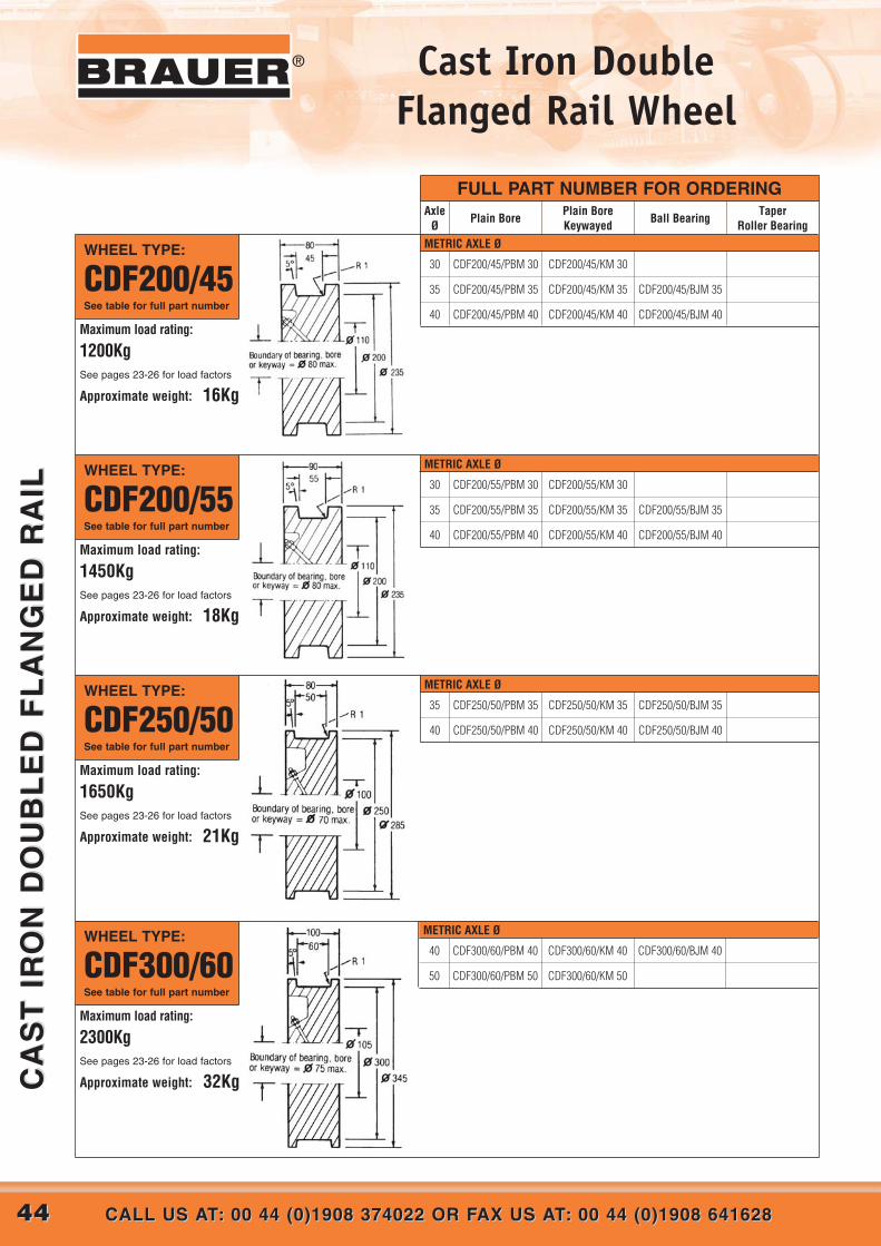
4444 CALL US AT: 00 44 (0)1908 374022 OR FAX US AT: 00 44 (0)1908 641628CALL US AT: 00 44 (0)1908 374022 OR FAX US AT: 00 44 (0)1908 641628
CA
ST
IR
ON
DO
UB
LE
D F
LA
NG
ED
RA
ILC
AS
T I
RO
N D
OU
BL
ED
FL
AN
GE
D R
AIL
® Cast Iron Double Flanged Rail Wheel
METRIC AXLE Ø
METRIC AXLE Ø
METRIC AXLE Ø
FULL PART NUMBER FOR ORDERING
WHEEL TYPE:
CDF200/55See table for full part number
WHEEL TYPE:
CDF250/50See table for full part number
WHEEL TYPE:
CDF300/60See table for full part number
AxleØ
Plain BorePlain Bore Keywayed
Ball BearingTaper
Roller Bearing
35
40
CDF250/50/PBM 35
CDF250/50/PBM 40
CDF250/50/KM 35
CDF250/50/KM 40
CDF250/50/BJM 35
CDF250/50/BJM 40
40
50
CDF300/60/PBM 40
CDF300/60/PBM 50
CDF300/60/KM 40
CDF300/60/KM 50
CDF300/60/BJM 40
30
35
40
CDF200/55/PBM 30
CDF200/55/PBM 35
CDF200/55/PBM 40
CDF200/55/KM 30
CDF200/55/KM 35
CDF200/55/KM 40
CDF200/55/BJM 35
CDF200/55/BJM 40Maximum load rating:
1450KgSee pages 23-26 for load factors
Approximate weight: 18Kg
Maximum load rating:
1650KgSee pages 23-26 for load factors
Approximate weight: 21Kg
Maximum load rating:
2300KgSee pages 23-26 for load factors
Approximate weight: 32Kg
WHEEL TYPE:
CDF200/45See table for full part number
30
35
40
CDF200/45/PBM 30
CDF200/45/PBM 35
CDF200/45/PBM 40
CDF200/45/KM 30
CDF200/45/KM 35
CDF200/45/KM 40
CDF200/45/BJM 35
CDF200/45/BJM 40Maximum load rating:
1200KgSee pages 23-26 for load factors
Approximate weight: 16Kg
METRIC AXLE Ø

Steel Flat TreadRail Wheels
4545WEB: www.brauer.co.uk EMAIL: [email protected]: www.brauer.co.uk EMAIL: [email protected]
ST
EE
L F
LA
T T
RE
AD
RA
ILS
TE
EL
FL
AT
TR
EA
D R
AIL
®
METRIC AXLE ØWHEEL TYPE:
SFT75/60See table for full part number
25
30
SFT75/60/KM 25
SFT75/60/KM 30
SFT75/60/BJM 25
SFT75/60/BJM 30
SFT75/60/TBM 25
SFT75/60/TBM 30
Maximum load rating:
2300KgSee pages 23-26 for load factors
Approximate weight: 2Kg
While unflanged wheels can be used to run on surfaces such as concrete orsteel plate, their most common application is paired with a double flangedwheel, the flanged wheel providing guidance and the unflanged wheel allowinga wide tolerance in the pitch of the rails.
MATERIAL: Steel to BS970: 1983: 080M40
OPERATING TEMPERATURE RANGE:Plain bored or keywayed wheels – 30˚C to 350˚CBall or taper roller bearinged wheels – 30˚C to 120˚C
The ‘maximum load rating’ given for each wheel is based on the full treadwidth being in contact with the rail. Working loads must be calculated basedon the useable rail width and operating conditions – see ‘Design Data’ paras.6.1. and 6.2.
Alternative bore/bearing diameters and alternative bearing types (i.e. bronzebushes, self-lubricating bushes, roller bearings, spherical roller bearings,etc.) are available to order – see pages 26-27.
Plain bore wheels are not drilled and tapped for greasing unless requested attime of order.
For technical information covering load factors, inertial and rollingresistance, coefficients of friction between wheel and track, and keywaydimensions, see “Design Data” Index on page 20.
LOAD LIMITED BY BEARINGS TO: (1) 1140Kg (2) 2040Kg
Wheels fitted with ball journals are pre-lubricated, double shielded
(1)
(2)
FULL PART NUMBER FOR ORDERINGAxle
ØPlain Bore
Plain Bore Keywayed
Ball BearingTaper
Roller Bearing
METRIC AXLE ØWHEEL TYPE:
SFT100/60See table for full part number
25
30
SFT100/60/KM 25
SFT100/60/KM 30
SFT100/60/BJM 25
SFT100/60/BJM 30
SFT100/60/TBM 25
SFT100/60/TBM 30
Maximum load rating:
3100KgSee pages 23-26 for load factors
Approximate weight: 3.5Kg
LOAD LIMITED BY BEARINGS TO: (1) 1140Kg (2) 2040Kg
Wheels fitted with ball journals are pre-lubricated, double shielded
(1)
(2)

4646 CALL US AT: 00 44 (0)1908 374022 OR FAX US AT: 00 44 (0)1908 641628CALL US AT: 00 44 (0)1908 374022 OR FAX US AT: 00 44 (0)1908 641628
ST
EE
L F
LA
T T
RE
AD
RA
ILS
TE
EL
FL
AT
TR
EA
D R
AIL
® Steel Flat TreadRail Wheels
METRIC AXLE Ø
METRIC AXLE Ø
WHEEL TYPE:
SFT150/80See table for full part number
WHEEL TYPE:
SFT200/90See table for full part number
30
35
40
SFT150/80/KM 30
SFT150/80/KM 35
SFT150/80/KM 40
SFT150/80/BJM 30
SFT150/80/BJM 35
SFT150/80/BJM 40
SFT150/80/TBM 30
SFT150/80/TBM 35
SFT150/80/TBM 40
40
50
SFT200/90/KM 40
SFT200/90/KM 50
SFT200/90/BJM 40
SFT200/90/BJM 50
SFT200/90/TBM 40
SFT200/90/TBM 50
Maximum load rating:
6200KgSee pages 23-26 for load factors
Approximate weight: 10Kg
Maximum load rating:
9300KgSee pages 23-26 for load factors
Approximate weight: 22Kg
LOAD LIMITED BY BEARINGS TO: (1) 2040Kg (2) 2800Kg (3) 3384Kg (4) 5200Kg
LOAD LIMITED BY BEARINGS TO: (1) 3384Kg (2) 7340Kg (3) 8155Kg
(1)
(2)
(4)
(2)
(3)
(1) (3)
FULL PART NUMBER FOR ORDERINGAxle
ØPlain Bore
Plain Bore Keywayed
Ball BearingTaper
Roller Bearing
METRIC AXLE ØWHEEL TYPE:
SFT225/100See table for full part number
Maximum load rating:
11600KgSee pages 23-26for load factors
Approximate weight: 30Kg
50
60
SFT225/100/KM 50
SFT225/100/KM 60
SFT225/100/BJM 50
SFT225/100/BJM 60
SFT225/100/TBM 50
SFT225/100/TBM 60
(1) (3)
(2)
LOAD LIMITED BY BEARINGS TO: (1) 7340Kg (2) 9785Kg (3) 10600Kg
METRIC AXLE ØWHEEL TYPE:
SFT250/100See table for full part number
Maximum load rating:
12900KgSee pages 23-26 for load factors
Approximate weight: 37Kg
50
60
75
SFT250/100/KM 50
SFT250/100/KM 60
SFT250/100/KM 75
SFT250/100/BJM 50
SFT250/100/BJM 60
SFT250/100/BJM 75
SFT250/100/TBM 50
SFT250/100/TBM 60
SFT250/100/TBM 75
(1) (4)
(2)
(3)
LOAD LIMITED BY BEARINGS TO: (1) 7340Kg (2) 9785Kg (3) 9000Kg (4) 10600Kg

4747CALL US AT: 00 44 (0)1908 374022 OR FAX US AT: 00 44 (0)1908 641628CALL US AT: 00 44 (0)1908 374022 OR FAX US AT: 00 44 (0)1908 641628
ST
EE
L F
LA
T T
RE
AD
RA
ILS
TE
EL
FL
AT
TR
EA
D R
AIL
®Steel Flat TreadRail Wheels
METRIC AXLE Ø
METRIC AXLE Ø
METRIC AXLE ØWHEEL TYPE:
SFT350/110See table for full part number
WHEEL TYPE:
SFT450/125See table for full part number
WHEEL TYPE:
SFT600/150See table for full part number
INCH AXLE Ø
Maximum load rating:
19900KgSee pages 23-26 for load factors
Approximate weight: 80Kg
Maximum load rating:
29000KgSee pages 23-26 for load factors
Approximate weight:150Kg
Maximum load rating:
46300KgSee pages 23-26 for load factors
Approximate weight: 325Kg
LOAD LIMITED BY BEARINGS TO: (1) 7340Kg (2) 9785Kg (3) 9000Kg (4) 10600Kg(5) 13350Kg (6) 19400Kg
50
60
75
SFT350/110/KM 50
SFT350/110/KM 60
SFT350/110/KM 75
SFT350/110/BJM 50
SFT350/110/BJM 60
SFT350/110/BJM 75
SFT350/110/TBM 50
SFT350/110/TBM 60
SFT350/110/TBM 75
(2) (5)
(6) (3)
75
100
SFT450/125/KM 75
SFT450/125/KM 100
SFT450/125/TBM 75
SFT450/125/TBM 100
LOAD LIMITED BY BEARINGS TO: (1) 19400Kg
100
150
SFT600/150/KM 100
SFT600/150/KM 150
SFT600/150/TBM 100
SFT600/150/TBM 150
LOAD LIMITED BY BEARINGS TO: (1) 31000Kg
(1) (4)
(1)
FULL PART NUMBER FOR ORDERINGAxle
ØPlain Bore
Plain Bore Keywayed
Ball BearingTaper
Roller Bearing
(1)
METRIC AXLE ØWHEEL TYPE:
SFT300/100See table for full part number
Maximum load rating:
15400KgSee pages 23-26 for load factors
Approximate weight: 54Kg
LOAD LIMITED BY BEARINGS TO: (1) 7340Kg (2) 9785Kg (3) 9000Kg (4) 10600Kg(5) 13350Kg
50
60
75
SFT300/100/KM 50
SFT300/100/KM 60
SFT300/100/KM 75
SFT300/100/BJM 50
SFT300/100/BJM 60
SFT300/100/BJM 75
SFT300/100/TBM 50
SFT300/100/TBM 60
SFT300/100/TBM 75
(1)
(2)
(4)
(5)
(3)

4848 CALL US AT: 00 44 (0)1908 374022 OR FAX US AT: 00 44 (0)1908 641628CALL US AT: 00 44 (0)1908 374022 OR FAX US AT: 00 44 (0)1908 641628
CA
ST
IR
ON
FL
AT
TR
EA
D R
AIL
CA
ST
IR
ON
FL
AT
TR
EA
D R
AIL
® Cast Iron Flat Tread Rail Wheels
®
METRIC AXLE Ø
METRIC AXLE Ø
While unflanged wheels can be used to run on surfaces such as concrete orsteel plate, their most common application is paired with a double flangedwheel.
Cast iron rail wheels are the most economic for light to medium duty, butthey have a limited service life when compared to steel wheels, and areunsuitable for high rotational speeds or where substantial shock loads are tobe withstood.
MATERIAL: Cast iron to BS1452: 1977: Grade 200.
OPERATING TEMPERATURE RANGE:Plain bored or keywayed wheels – 30˚C to 250˚CBall or taper roller bearinged wheels – 30˚C to 120˚C
The ‘maximum load rating’ given for each wheel is based on the full treadwidth being in contact with the rail. Working loads must be calculated basedon the useable rail width and operating conditions – see ‘Design Data’ paras.6.1. and 6.3.
Alternative bore/bearing diameters and alternative bearing types (i.e. bronzebushes, self-lubricating bushes, roller bearings, spherical roller bearings,etc.) are available to order – see page 26-27.
For technical information covering load factors, inertial and rollingresistance, coefficients of friction between wheel and track, and keywaydimensions, see “Design Data” Index on page 20.
FULL PART NUMBER FOR ORDERING
WHEEL TYPE:
CFT130/70See table for full part number
WHEEL TYPE:
CFT150/80See table for full part number
AxleØ
Plain BorePlain Bore Keywayed
Ball BearingTaper
Roller Bearing
30
35
40
CFT150/80/PBM 30
CFT150/80/PBM 35
CFT150/80/PBM 40
CFT150/80/KM 30
CFT150/80/KM 35
CFT150/80/KM 40
CFT150/80/BJM 30
CFT150/80/BJM 35
CFT150/80/BJM 40
25
30
35
CFT130/70/PBM 25
CFT130/70/PBM 30
CFT130/70/PBM 35
CFT130/70/KM 25
CFT130/70/KM 30
CFT130/70/KM 35
CFT130/70/BJM 25
CFT130/70/BJM 30
CFT130/70/BJM 35Maximum load rating:
1200KgSee pages 23-26 for load factors
Approximate weight: 7Kg
Maximum load rating:
1500KgSee pages 23-26 for load factors
Approximate weight: 10Kg
Wheels fitted with 35mm ball journals are pre-lubricated, double shielded
LOAD LIMITED BY BEARINGS TO: (1) 1140Kg
(1)
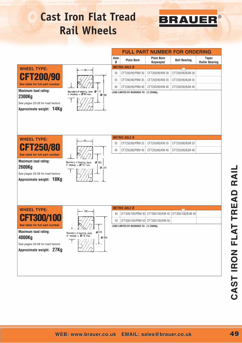
4949WEB: www.brauer.co.uk EMAIL: [email protected]: www.brauer.co.uk EMAIL: [email protected]
CA
ST
IR
ON
FL
AT
TR
EA
D R
AIL
CA
ST
IR
ON
FL
AT
TR
EA
D R
AIL
®Cast Iron Flat Tread Rail Wheels
®
METRIC AXLE Ø
METRIC AXLE Ø
WHEEL TYPE:
CFT250/80See table for full part number
WHEEL TYPE:
CFT300/100See table for full part number
FULL PART NUMBER FOR ORDERINGAxle
ØPlain Bore
Plain Bore Keywayed
Ball BearingTaper
Roller Bearing
Maximum load rating:
4000KgSee pages 23-26 for load factors
Approximate weight: 27Kg
Maximum load rating:
2600KgSee pages 23-26 for load factors
Approximate weight: 18Kg
35
40
CFT250/80/PBM 35
CFT250/80/PBM 40
CFT250/80/KM 35
CFT250/80/KM 40
CFT250/80/BJM 35
CFT250/80/BJM 40
40
50
CFT300/100/PBM 40
CFT300/100/PBM 50
CFT300/100/KM 40
CFT300/100/KM 50
CFT300/100/BJM 40
METRIC AXLE ØWHEEL TYPE:
CFT200/90See table for full part number
30
35
40
CFT200/90/PBM 30
CFT200/90/PBM 35
CFT200/90/PBM 40
CFT200/90/KM 30
CFT200/90/KM 35
CFT200/90/KM 40
CFT200/90/BJM 30
CFT200/90/BJM 35
CFT200/90/BJM 40Maximum load rating:
2300KgSee pages 23-26 for load factors
Approximate weight: 14Kg
LOAD LIMITED BY BEARINGS TO: (1) 3384Kg
(1)
(1)
LOAD LIMITED BY BEARINGS TO: (1) 2040Kg

NFT250/60/BJM40
NFT250/60/PBM35
NFT250/60/PBM40
NFT250/60/PBM50
5050 CALL US AT: 00 44 (0)1908 374022 OR FAX US AT: 00 44 (0)1908 641628CALL US AT: 00 44 (0)1908 374022 OR FAX US AT: 00 44 (0)1908 641628
CA
ST
NY
LO
N R
AN
GE
CA
ST
NY
LO
N R
AN
GE
® Cast Nylon Flat Tread Rail Wheels
METRIC AXLE Ø
WHEEL TYPE:
NFT200/60See table for full part number
30
35
NFT200/60/PBM30
NFT200/60/PBM35
NFT200/60/BJM30
LOAD LIMITED BY BEARINGS TO: (1) 2040Kg
(1)
FULL PART NUMBER FOR ORDERINGAxle
ØPlain Bore Ball Bearing
METRIC AXLE ØWHEEL TYPE:
NFT250/60See table for full part number
Maximum load rating:
2950KgSee page 21 for load factors
Approximate weight: 3.2Kg
35
40
50
LOAD LIMITED BY BEARINGS TO: (1) 3384Kg
®
METRIC AXLE ØWHEEL TYPE:
NFT250/75See table for full part number
Maximum load rating:
3680KgSee page 21 for load factors
Approximate weight: 4Kg
35
40
50
NFT250/75/PBM35
NFT250/75/PBM40
NFT250/75/PBM50
NFT250/75/BJM40
Maximum load rating:
2350KgSee page 21 for load factors
Approximate weight: 2Kg
Nylon wheels are light in weight and are resistant to impact, abrasion,corrosion and the effect of many chemicals.
While unflanged wheels can be used to run on surfaces such as concreteor steel plate, their most common application is paired with a doubleflanged wheel, the flanged wheel providing guidance and the unflangedwheel allowing a wide tolerance in the pitch of the rails.
MATERIAL: Cast Nylon 6
OPERATING TEMPERATURE RANGE:Plain bored or keywayed wheels – 30˚C to 80˚CBall or taper roller bearinged wheels – 30˚C to 80˚C
The ‘maximum load rating’ given for each wheel is based on the full treadwidth being in contact with the rail. Working loads must be calculatedbased on the useable rail width and operating conditions – see ‘DesignData’ paras. 6.1. and 6.2.
Alternative bore/bearing diameters and alternative bearing types(i.e. bronze bushes, self-lubricating bushes, roller bearings, sphericalroller bearings, etc.) are available to order – see pages 23-28.
Plain bore wheels are not drilled and tapped for greasing unlessrequested at time of order.
For technical information covering load factors, inertial and rollingresistance, coefficients of friction between wheel and track, andkeyway dimensions, see “Design Data” Index on page 20.
LOAD LIMITED BY BEARINGS TO: (1) 3384Kg
(1)
(1)
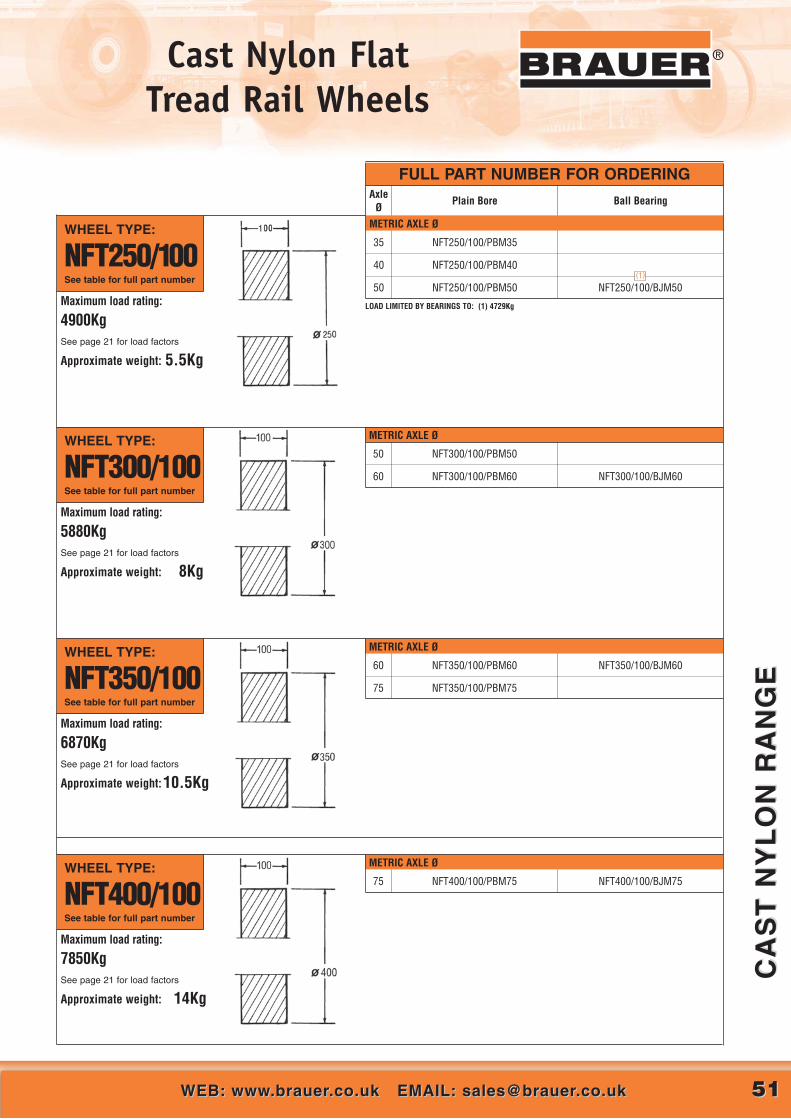
METRIC AXLE Ø
60
75
NFT350/100/PBM60
NFT350/100/PBM75
NFT350/100/BJM60
5151WEB: www.brauer.co.uk EMAIL: [email protected]: www.brauer.co.uk EMAIL: [email protected]
CA
ST
NY
LO
N R
AN
GE
CA
ST
NY
LO
N R
AN
GE
®Cast Nylon Flat Tread Rail Wheels
Maximum load rating:
4900KgSee page 21 for load factors
Approximate weight: 5.5Kg
®
METRIC AXLE Ø
WHEEL TYPE:
NFT250/100See table for full part number
WHEEL TYPE:
NFT300/100See table for full part number
WHEEL TYPE:
NFT350/100See table for full part number
INCH AXLE Ø
Maximum load rating:
5880KgSee page 21 for load factors
Approximate weight: 8Kg
LOAD LIMITED BY BEARINGS TO: (1) 4729Kg
50
60
NFT300/100/PBM50
NFT300/100/PBM60 NFT300/100/BJM60
Maximum load rating:
6870KgSee page 21 for load factors
Approximate weight:10.5Kg
METRIC AXLE Ø
75 NFT400/100/PBM75 NFT400/100/BJM75WHEEL TYPE:
NFT400/100See table for full part number
Maximum load rating:
7850KgSee page 21 for load factors
Approximate weight: 14Kg
METRIC AXLE Ø
35
40
50
NFT250/100/PBM35
NFT250/100/PBM40
NFT250/100/PBM50 NFT250/100/BJM50
FULL PART NUMBER FOR ORDERINGAxle
ØPlain Bore Ball Bearing
(1)

5252 CALL US AT: 00 44 (0)1908 374022 OR FAX US AT: 00 44 (0)1908 641628CALL US AT: 00 44 (0)1908 374022 OR FAX US AT: 00 44 (0)1908 641628
CA
ST
NY
LO
N R
AN
GE
CA
ST
NY
LO
N R
AN
GE
® Cast Nylon Double Flanged Rail Wheels
NDF250/60/BJM30NDF250/60/PBM30
NDF250/60/PBM35
METRIC AXLE ØWHEEL TYPE:
NDF200/60See table for full part number
25
30
NDF200/60/PBM25
NDF200/60/PBM30
NDF200/60/BJM25
LOAD LIMITED BY BEARINGS TO: (1) 1140Kg
(1)
FULL PART NUMBER FOR ORDERINGAxle
ØPlain Bore Ball Bearing
METRIC AXLE ØWHEEL TYPE:
NDF250/60See table for full part number
Maximum load rating:
2453KgSee page 21 for load factors
Approximate weight: 5.5Kg
30
35
Maximum load rating:
1960KgSee page 21 for load factors
Approximate weight: 4Kg
LOAD LIMITED BY BEARINGS TO: (1) 2040Kg
(1)
Nylon wheels are light in weight and are resistant to impact, abrasion,corrosion and the effect of many chemicals.
Flanged wheels can be used for guidance paired with an unflanged rail wheelto allow a wide tolerance in the pitch of the rails.
MATERIAL: Cast Nylon 6
OPERATING TEMPERATURE RANGE:Plain bored or keywayed wheels – 30˚C to 80˚CBall or taper roller bearinged wheels – 30˚C to 80˚C
The ‘maximum load rating’ given for each wheel is based on the full treadwidth being in contact with the rail. Working loads must be calculated basedon the useable rail width and operating conditions – see ‘Design Data’ paras.6.1. and 6.2.
Alternative bore/bearing diameters and alternative bearing types (i.e. bronzebushes, self-lubricating bushes, roller bearings, spherical roller bearings,etc.) are available to order – see pages 23-28.
Plain bore wheels are not drilled and taped for greasing unless requested attime of order.
For technical information covering load factors, inertial and rollingresistance, coefficients of friction between wheel and track, and keywaydimensions, see “Design Data” Index on page 20.

5353WEB: www.brauer.co.uk EMAIL: [email protected]: www.brauer.co.uk EMAIL: [email protected]
CA
ST
NY
LO
N R
AN
GE
CA
ST
NY
LO
N R
AN
GE
®®®Cast Nylon Double Flanged Rail Wheels
NDF350/60/BJM50NDF350/60/PBM50
NDF350/60/PBM60
METRIC AXLE ØWHEEL TYPE:
NDF300/60See table for full part number
40
50
NDF300/60/PBM40
NDF300/60/PBM50
NDF300/60/BJM40
LOAD LIMITED BY BEARINGS TO: (1) 3384Kg
FULL PART NUMBER FOR ORDERINGAxle
ØPlain Bore Ball Bearing
METRIC AXLE ØWHEEL TYPE:
NDF350/60See table for full part number
Maximum load rating:
4120KgSee page 21 for load factors
Approximate weight: 11Kg
50
60
METRIC AXLE ØWHEEL TYPE:
NDF400/60See table for full part number
Maximum load rating:
4770KgSee page 21 for load factors
Approximate weight: 14Kg
LOAD LIMITED BY BEARINGS TO: (1) 4729Kg
50
60
NDF400/60/PBM50
NDF400/60/PBM60
NDF400/60/BJM50
Maximum load rating:
3530KgSee page 21 for load factors
Approximate weight: 8Kg
(1)
(1)

5454 CALL US AT: 00 44 (0)1908 374022 OR FAX US AT: 00 44 (0)1908 641628CALL US AT: 00 44 (0)1908 374022 OR FAX US AT: 00 44 (0)1908 641628
ST
EE
L ‘
V’
GR
OO
VE
DS
TE
EL
‘V
’ G
RO
OV
ED
® Steel ‘V’ Grooved Wheels®
METRIC AXLE Ø
METRIC AXLE Ø
Steel 90˚ ‘V’ grooved wheels offer an economic form of rail guidance beingsuitable for running on inverted angle iron rail.
MATERIAL: Steel to BS970: Part 1: 1983: 080 M40
Alternative bore/bearing diameters and alternative bearing types (i.e. bronzebushers, self-lubricating bushes, high temperature bearings, spherical rollerbearings, etc.) are available to order. See page 26-27.
For technical information covering load factors, inertial and rollingresistance, coefficients of friction between wheel and track and keywaydimensions, see “Design Data” Index on page 20.
FULL PART NUMBER FOR ORDERING
WHEEL TYPE:
SVT75/35See table for full part number
WHEEL TYPE:
SVT100/40See table for full part number
AxleØ
Plain BorePlain Bore Keywayed
Ball BearingTaper
Roller Bearing
12
20
SVT75/35/KM 12
SVT75/35/KM 20
SVT75/35/BJM 12
SVT75/35/BJM 20
Maximum load rating:
800KgSee pages 23-26 for load factors
Approximate weight: 1Kg
Maximum load rating:
1100KgSee pages 23-26 for load factors
Approximate weight: 2Kg
20
25
SVT100/40/KM 20
SVT100/40/KM 25
SVT100/40/BJM 20
SVT100/40/BJM 25
Wheels fitted with ball journals are pre-lubricated, double shielded
Wheels fitted with ball journals are pre-lubricated, double shielded
(1)
(1)
LOAD LIMITED BY BEARINGS TO: (1) 570Kg
LOAD LIMITED BY BEARINGS TO: (1) 900Kg
METRIC AXLE ØWHEEL TYPE:
SVT125/40See table for full part number
Maximum load rating:
1500KgSee pages 23-26 for load factors
Approximate weight: 3.4Kg
20
25
30
SVT125/40/KM 20
SVT125/40/KM 25
SVT125/40/KM 30
SVT125/40/BJM 20
SVT125/40/BJM 25
SVT125/40/BJM 30
Wheels fitted with ball journals are pre-lubricated, double shielded
(1)
(2)
LOAD LIMITED BY BEARINGS TO: (1) 900Kg (2) 1140Kg

5555WEB: www.brauer.co.uk EMAIL: [email protected]: www.brauer.co.uk EMAIL: [email protected]
ST
EE
L ‘
V’
GR
OO
VE
DS
TE
EL
‘V
’ G
RO
OV
ED
®Steel ‘V’ Grooved Wheels ®
METRIC AXLE Ø
METRIC AXLE Ø
FULL PART NUMBER FOR ORDERING
WHEEL TYPE:
SVT150/45See table for full part number
AxleØ
Plain BorePlain Bore Keywayed
Ball BearingTaper
Roller Bearing
Maximum load rating:
2200KgSee pages 23-26 for load factors
Approximate weight: 5.2kg
25
30
35
SVT150/45/KM 25
SVT150/45/KM 30
SVT150/45/KM 35
SVT150/45/BJM 25
SVT150/45/BJM 30
SVT150/45/BJM 35
(1)
(2)
LOAD LIMITED BY BEARINGS TO: (1) 1140Kg (2) 2040Kg
WHEEL TYPE:
SVT200/50See table for full part number
Maximum load rating:
3000KgSee pages 23-26 for load factors
Approximate weight: 11Kg
30
35
40
SVT200/50/KM 30
SVT200/50/KM 35
SVT200/50/KM 40
SVT200/50/BJM 30
SVT200/50/BJM 35
SVT200/50/BJM 40
(1)
(2)
LOAD LIMITED BY BEARINGS TO: (1) 2040Kg (2) 2800Kg
METRIC AXLE ØWHEEL TYPE:
SVT250/60See table for full part number
Maximum load rating:
4750KgSee pages 23-26 for load factors
Approximate weight: 23Kg
35
40
50
SVT250/60/KM 35
SVT250/60/KM 40
SVT250/60/KM 50
SVT250/60/BJM 35
SVT250/60/BJM 40
SVT250/60/BJM 50
(1)
(2)
LOAD LIMITED BY BEARINGS TO: (1) 2800Kg (2) 3384Kg
METRIC AXLE ØWHEEL TYPE:
SVT300/70See table for full part number
Maximum load rating:
7100KgSee pages 23-26 for load factors
Approximate weight: 38Kg
40
50
60
SVT300/70/KM 40
SVT300/70/KM 50
SVT300/70/KM 60
SVT300/70/BJM 40
SVT300/70/BJM 50
SVT300/70/BJM 60
(1)
LOAD LIMITED BY BEARINGS TO: (1) 3384Kg
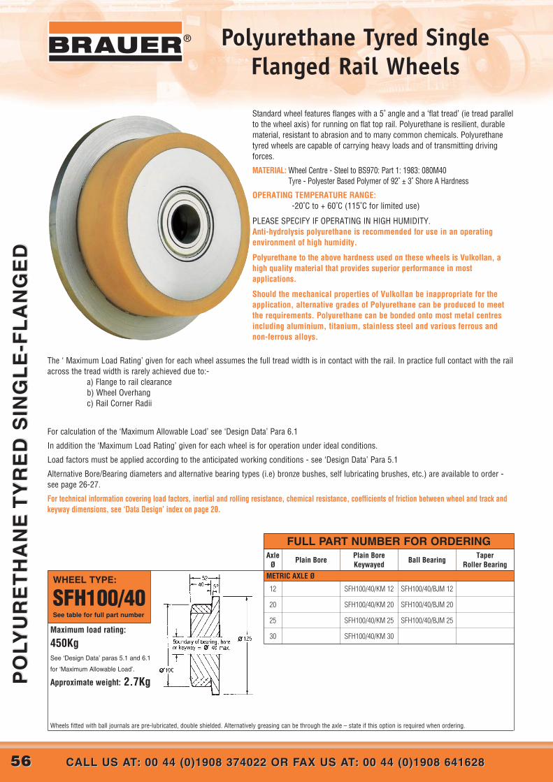
5656 CALL US AT: 00 44 (0)1908 374022 OR FAX US AT: 00 44 (0)1908 641628CALL US AT: 00 44 (0)1908 374022 OR FAX US AT: 00 44 (0)1908 641628
PO
LYU
RE
TH
AN
E T
YR
ED
SIN
GL
E-F
LA
NG
ED
PO
LYU
RE
TH
AN
E T
YR
ED
SIN
GL
E-F
LA
NG
ED
® Polyurethane Tyred SingleFlanged Rail Wheels
METRIC AXLE Ø
Standard wheel features flanges with a 5˚ angle and a ‘flat tread’ (ie tread parallelto the wheel axis) for running on flat top rail. Polyurethane is resilient, durablematerial, resistant to abrasion and to many common chemicals. Polyurethanetyred wheels are capable of carrying heavy loads and of transmitting drivingforces.
MATERIAL: Wheel Centre - Steel to BS970: Part 1: 1983: 080M40Tyre - Polyester Based Polymer of 92˚ ± 3˚ Shore A Hardness
OPERATING TEMPERATURE RANGE: -20˚C to + 60˚C (115˚C for limited use)
PLEASE SPECIFY IF OPERATING IN HIGH HUMIDITY.Anti-hydrolysis polyurethane is recommended for use in an operatingenvironment of high humidity.
Polyurethane to the above hardness used on these wheels is Vulkollan, ahigh quality material that provides superior performance in mostapplications.
Should the mechanical properties of Vulkollan be inappropriate for theapplication, alternative grades of Polyurethane can be produced to meetthe requirements. Polyurethane can be bonded onto most metal centresincluding aluminium, titanium, stainless steel and various ferrous andnon-ferrous alloys.
The ‘ Maximum Load Rating’ given for each wheel assumes the full tread width is in contact with the rail. In practice full contact with the railacross the tread width is rarely achieved due to:-
a) Flange to rail clearanceb) Wheel Overhangc) Rail Corner Radii
For calculation of the ‘Maximum Allowable Load’ see ‘Design Data’ Para 6.1
In addition the ‘Maximum Load Rating’ given for each wheel is for operation under ideal conditions.
Load factors must be applied according to the anticipated working conditions - see ‘Design Data’ Para 5.1
Alternative Bore/Bearing diameters and alternative bearing types (i.e) bronze bushes, self lubricating brushes, etc.) are available to order -see page 26-27.
For technical information covering load factors, inertial and rolling resistance, chemical resistance, coefficients of friction between wheel and track andkeyway dimensions, see ‘Data Design’ index on page 20.
FULL PART NUMBER FOR ORDERING
WHEEL TYPE:
SFH100/40See table for full part number
AxleØ
Plain BorePlain Bore Keywayed
Ball BearingTaper
Roller Bearing
12
20
25
30
SFH100/40/KM 12
SFH100/40/KM 20
SFH100/40/KM 25
SFH100/40/KM 30
SFH100/40/BJM 12
SFH100/40/BJM 20
SFH100/40/BJM 25Maximum load rating:
450KgSee ‘Design Data’ paras 5.1 and 6.1
for ‘Maximum Allowable Load’.
Approximate weight: 2.7Kg
Wheels fitted with ball journals are pre-lubricated, double shielded. Alternatively greasing can be through the axle – state if this option is required when ordering.

5757WEB: www.brauer.co.uk EMAIL: [email protected]: www.brauer.co.uk EMAIL: [email protected]
PO
LYU
RE
TH
AN
E T
YR
ED
SIN
GL
E-F
LA
NG
ED
PO
LYU
RE
TH
AN
E T
YR
ED
SIN
GL
E-F
LA
NG
ED
®Polyurethane Tyred SingleFlanged Rail Wheels
METRIC AXLE Ø
METRIC AXLE Ø
20
25
30
35
SFH150/50/KM 20
SFH150/50/KM 25
SFH150/50/KM 30
SFH150/50/KM 35
SFH150/50/BJM 20
SFH150/50/BJM 25
SFH150/50/BJM 30
SFH150/50/BJM 35
25
30
35
40
SFH200/60/KM 25
SFH200/60/KM 30
SFH200/60/KM 35
SFH200/60/KM 40
SFH200/60/BJM 25
SFH200/60/BJM 30
SFH200/60/BJM 35
SFH200/60/BJM 40
WHEEL TYPE:
SFH150/50See table for full part number
Maximum load rating:
850KgSee ‘Design Data’ paras 5.1 and 6.1
for ‘Maximum Allowable Load’.
Approximate weight: 7.6Kg
WHEEL TYPE:
SFH200/60See table for full part number
Maximum load rating:
1400KgSee ‘Design Data’ paras 5.1 and 6.1
for ‘Maximum Allowable Load’.
Approximate weight: 17Kg
FULL PART NUMBER FOR ORDERINGAxle
ØPlain Bore
Plain Bore Keywayed
Ball BearingTaper
Roller BearingMETRIC AXLE ØWHEEL TYPE:
SFH125/45See table for full part number
12
20
25
30
SFH125/45/KM 12
SFH125/45/KM 20
SFH125/45/KM 25
SFH125/45/KM 30
SFH125/45/BJM 12
SFH125/45/BJM 20
SFH125/45/BJM 25
SFH125/45/BJM 30
Wheels fitted with ball journals are pre-lubricated, double shielded. Alternatively greasing can be through the axle – state if this option is required when ordering.
Wheels fitted with ball journals are pre-lubricated, double shielded. Alternatively greasing can be through the axle – state if this option is required when ordering.
Wheels fitted with ball journals are pre-lubricated, double shielded. Alternatively greasing can be through the axle – state if this option is required when ordering.
Maximum load rating:
650KgSee ‘Design Data’ paras 5.1 and 6.1
for ‘Maximum Allowable Load’.
Approximate weight: 4.7Kg
(1)
LOAD LIMITED BY BEARINGS TO: (1) 570Kg
(1)
LOAD LIMITED BY BEARINGS TO: (1) 1140Kg

5858 CALL US AT: 00 44 (0)1908 374022 OR FAX US AT: 00 44 (0)1908 641628CALL US AT: 00 44 (0)1908 374022 OR FAX US AT: 00 44 (0)1908 641628
SIN
GL
E F
LA
NG
ED
‘I’
BE
AM
& C
HA
NN
EL
SIN
GL
E F
LA
NG
ED
‘I’
BE
AM
& C
HA
NN
EL
® Single Flanged ‘I’ Beam &Channel Wheels - Flat Tread
PART NUMBER:
SSFF150/35/BJA
5˚Ø30
Ø150
Ø180
R135
502072
R2
M36 x 3
46 A/F HEX
Maximum load rating:
1500KgSee pages 23-26 for load factors
Approximate weight:7.5Kg
PART NUMBER:
SSFF200/35/BJA
5˚Ø40
Ø200
Ø230
R135
502072
R3
M42 x 3
50 A/F HEX
Maximum load rating:
2000KgSee pages 23-26 for load factors
Approximate weight: 12Kg
PART NUMBER:
SSFF55/25/BJA
5˚Ø20
Ø55 Ø70
R125
351552
R2
M24 x 2
30 A/F HEX
Maximum load rating:
370KgSee pages 23-26 for load factors
Approximate weight:1.1Kg
PART NUMBER:
SSFF80/25/BJA
5˚Ø25
Ø80 Ø95
R125
351562
R2
M24 x�232 A/F HEX
Maximum load rating:
700KgSee pages 23-26 for load factors
Approximate weight: 2Kg
PART NUMBER:
SSFF100/25/BJA
5˚Ø25
Ø100
Ø115
R125
351962
R2
M30 x 2
36 A/F HEX
Maximum load rating:
1000KgSee pages 23-26 for load factors
Approximate weight: 4Kg
Brauer has added a flat version to its popular “I’ beam and channel radiusedtread and wheel range. The new steel, flat tread, single flanged range isdesigned to suit parallel flanged channels and universal beams (to BS4,Part I 1993). The axles have been significantly upgraded to increase the loadcarrying capacity of the assembly.
MATERIAL: Steel to BS970: Part 1: 1983: 080M40
OPERATING TEMPERATURE RANGE:-30˚C to 120˚C.
When shock loadings are to be withstood the ‘maximum load rating’ shouldbe reduced by multiplying by a shock loading factor of 0.65.

5959WEB: www.brauer.co.uk EMAIL: [email protected]: www.brauer.co.uk EMAIL: [email protected]
SIN
GL
E F
LA
NG
ED
‘I’
BE
AM
& C
HA
NN
EL
SIN
GL
E F
LA
NG
ED
‘I’
BE
AM
& C
HA
NN
EL
®Single Flanged ‘I’ Beam &Channel Wheels - Radius Tread
The SFR (cast iron) and SSFR (Steel) ranges of wheel assemblies have beendesigned to fit within standard sections of channel and ‘I’ beams. Theradiused tread accommodates the angle of the section and improves the wearand tracking characteristics.
MATERIAL: SFR series – Cast iron to BS1452: 1977: Grade 200SSFR series – Steel to BS970: Part 1: 1983: 080M40Axles – Steel to BS970: Part 1: 1983: 606M36 or 605M36
OPERATING TEMPERATURE RANGE:-30˚C to 120˚C.
SFR (cast iron) wheels are not suitable where substantial shock loads are tobe withstood, and they have a limited service life in comparison with theequivalent SSFR wheel.
When shock loadings are to be withstood by either the SFR or SSFR rangesthe ‘maximum load rating’ should be reduced by multiplying by a shockloading factor of 0.65.
PART NUMBER:
SSFR55/25/BJA
Maximum load rating:
160KgSee pages 23-26 for load factors
Approximate weight: 1Kg
PART NUMBER:
SSFR85/25/BJA
Maximum load rating:
370KgSee pages 23-26 for load factors
Approximate weight:2.5Kg
PART NUMBER:
SSFR105/25/BJA
Maximum load rating:
700KgSee pages 23-26 for load factors
Approximate weight: 4kg
PART NUMBER:
SSFR133/35/BJA
Maximum load rating:
1000KgSee pages 23-26 for load factors
Approximate weight: 7Kg
PART NUMBER:
SSFR175/35/BJA
Maximum load rating: 1500KgSee pages 23-26 for load factors
Approximate weight: 11.5Kg
PART NUMBER:
SFR133/35/BJA
Maximum load rating:
600KgSee pages 23-26 for load factors
Approximate weight: 5Kg
PART NUMBER:
SFR175/35/BJA
Maximum load rating:
800KgSee pages 23-26 for load factors
Approximate weight: 8Kg
SSFR STEEL SERIES
SFR CAST-IRON SERIES

6060 CALL US AT: 00 44 (0)1908 374022 OR FAX US AT: 00 44 (0)1908 641628CALL US AT: 00 44 (0)1908 374022 OR FAX US AT: 00 44 (0)1908 641628
RA
ILR
AIL
®
RAIL SECTION
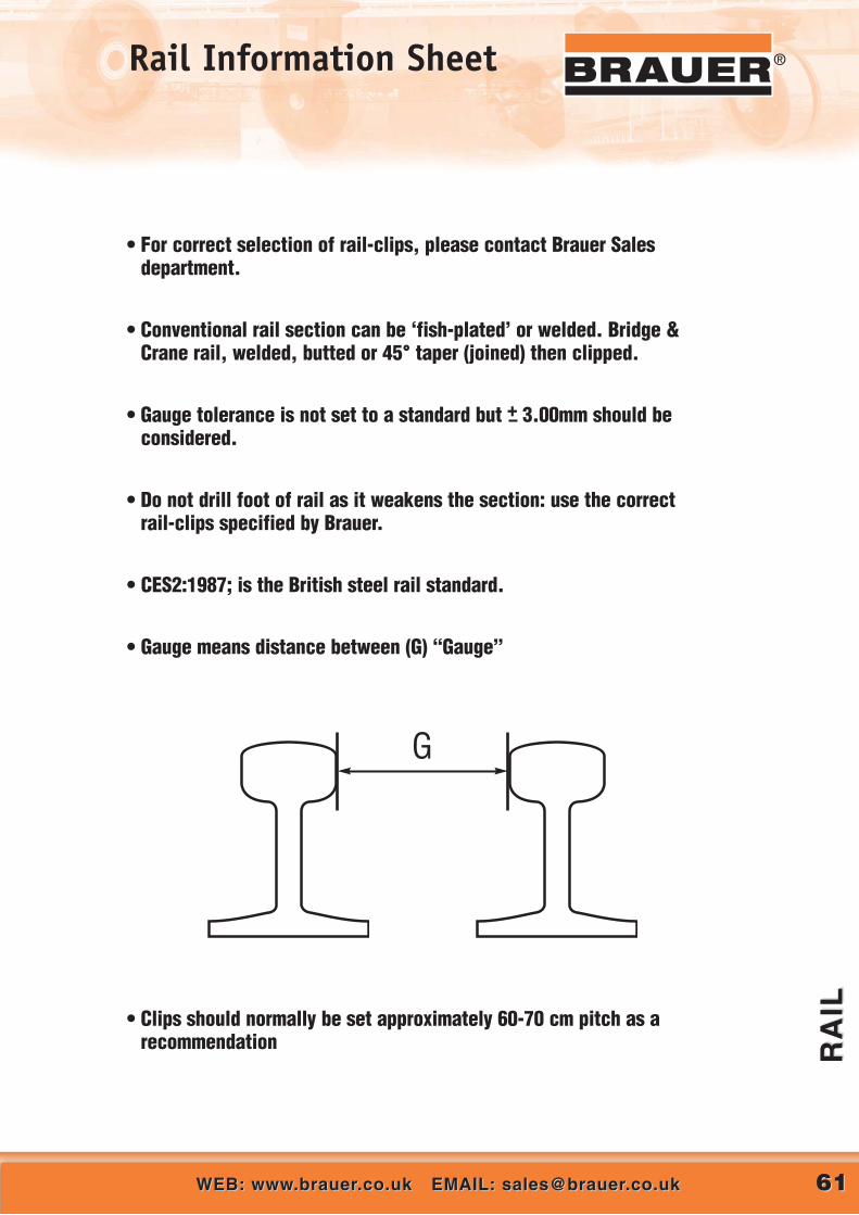
6161WEB: www.brauer.co.uk EMAIL: [email protected]: www.brauer.co.uk EMAIL: [email protected]
RA
ILR
AIL
®Rail Information Sheet
• For correct selection of rail-clips, please contact Brauer Salesdepartment.
• Conventional rail section can be ‘fish-plated’ or welded. Bridge &Crane rail, welded, butted or 45° taper (joined) then clipped.
• Gauge tolerance is not set to a standard but + 3.00mm should beconsidered.
• Do not drill foot of rail as it weakens the section: use the correct rail-clips specified by Brauer .
• CES2:1987; is the British steel rail standard.
• Gauge means distance between (G) “Gauge”
• Clips should normally be set approximately 60-70 cm pitch as arecommendation
G
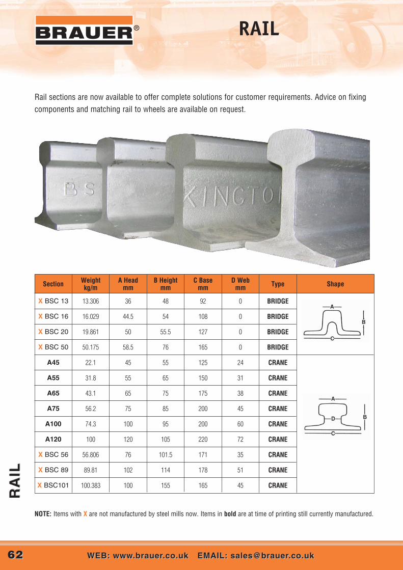
RA
ILR
AIL
6262 WEB: www.brauer.co.uk EMAIL: [email protected]: www.brauer.co.uk EMAIL: [email protected]
® RAIL
Section
X BSC 13 13.306 36 48 92 0 BRIDGE
X BSC 16 16.029 44.5 54 108 0 BRIDGE
X BSC 20 19.861 50 55.5 127 0 BRIDGE
X BSC 50 50.175 58.5 76 165 0 BRIDGE
A45 22.1 45 55 125 24 CRANE
A55 31.8 55 65 150 31 CRANE
A65 43.1 65 75 175 38 CRANE
A75 56.2 75 85 200 45 CRANE
A100 74.3 100 95 200 60 CRANE
A120 100 120 105 220 72 CRANE
X BSC 56 56.806 76 101.5 171 35 CRANE
X BSC 89 89.81 102 114 178 51 CRANE
Weight kg/m
A Head mm
B Heightmm
C Basemm
D Webmm Type Shape
Rail sections are now available to offer complete solutions for customer requirements. Advice on fixingcomponents and matching rail to wheels are available on request.
X BSC101 100.383 100 155 165 45 CRANE
NOTE: Items with X are not manufactured by steel mills now. Items in bold are at time of printing still currently manufactured.
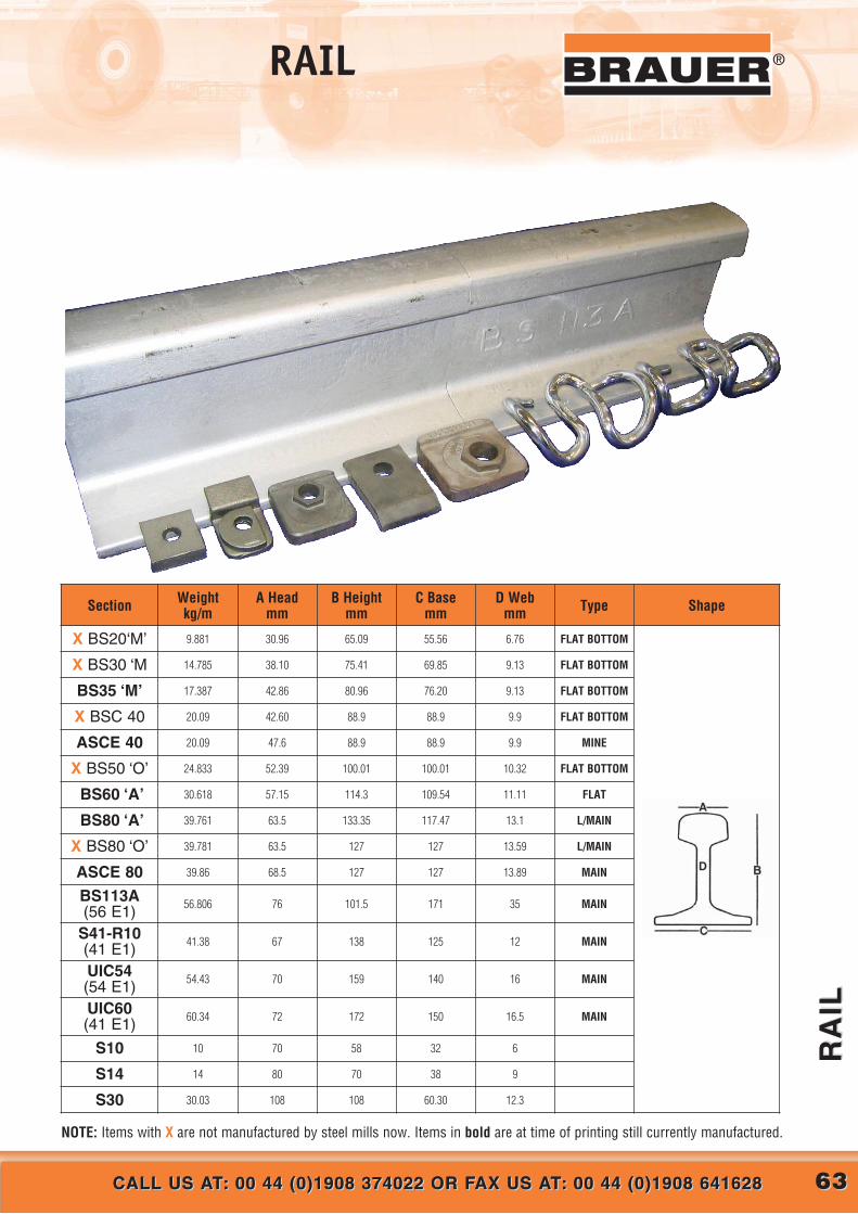
RA
ILR
AIL
CALL US AT: 00 44 (0)1908 374022 OR FAX US AT: 00 44 (0)1908 641628CALL US AT: 00 44 (0)1908 374022 OR FAX US AT: 00 44 (0)1908 641628
®RAIL
NOTE: Items with X are not manufactured by steel mills now. Items in bold are at time of printing still currently manufactured.
Section Weight kg/m
A Head mm
B Heightmm
C Basemm
D Webmm Type Shape
X BS20‘M’ 9.881 30.96 65.09 55.56 6.76 FLAT BOTTOM
X BS30 ‘M 14.785 38.10 75.41 69.85 9.13 FLAT BOTTOM
BS35 ‘M’ 17.387 42.86 80.96 76.20 9.13 FLAT BOTTOM
X BSC 40 20.09 42.60 88.9 88.9 9.9 FLAT BOTTOM
ASCE 40 20.09 47.6 88.9 88.9 9.9 MINE
X BS50 ‘O’ 24.833 52.39 100.01 100.01 10.32 FLAT BOTTOM
BS60 ‘A’ 30.618 57.15 114.3 109.54 11.11 FLAT
BS80 ‘A’ 39.761 63.5 133.35 117.47 13.1 L/MAIN
X BS80 ‘O’ 39.781 63.5 127 127 13.59 L/MAIN
ASCE 80 39.86 68.5 127 127 13.89 MAIN
BS113A(56 E1) 56.806 76 101.5 171 35 MAIN
S41-R10(41 E1) 41.38 67 138 125 12 MAIN
UIC54(54 E1) 54.43 70 159 140 16 MAIN
UIC60(41 E1) 60.34 72 172 150 16.5 MAIN
S10 10 70 58 32 6
S14 14 80 70 38 9
S30 30.03 108 108 60.30 12.3
6363CALL US AT: 00 44 (0)1908 374022 OR FAX US AT: 00 44 (0)1908 641628CALL US AT: 00 44 (0)1908 374022 OR FAX US AT: 00 44 (0)1908 641628

6464 CALL US AT: 00 44 (0)1908 374022 OR FAX US AT: 00 44 (0)1908 641628CALL US AT: 00 44 (0)1908 374022 OR FAX US AT: 00 44 (0)1908 641628
CA
ST
IR
ON
UN
TY
RE
DC
AS
T I
RO
N U
NT
YR
ED
® Cast Iron Untyred Wheels
METRIC AXLE Ø
METRIC AXLE Ø
Untyred wheels can carry high loads with low rolling resistance when used ona hard surface such as flat steel. On softer surfaces, such as concrete ortarmac, the surface is likely to be worn or indented by the use of an untyredwheel. Untyred wheels are noisier in operation than tyred wheels, but noise isunlikely to be a problem at walking speeds.
MATERIAL: Cast iron to BS1452: 1977: Grade 200.
OPERATING TEMPERATURE RANGE:Plain bored or keywayed wheels – 30˚C to 250˚CBall or taper roller bearinged wheels – 30˚C to 120˚C
Alternative bore/bearing diameters and alternative bearing types (i.e. bronzebushes, self-lubricating bushes, roller bearings, spherical roller bearings,etc.) are available to order – see page 26-27.
For wheels of larger diameter or greater load capacity see the CFT series(pages 48 & 49) and SFT series (pages 45-47).
For technical information covering load factors, inertial and rollingresistance, coefficients of friction between wheel and track, and keywaydimensions, see “Design Data” Index on page 20.
Drawings show grease nipple but standard wheels do not come with greasenipple unless specifically requested.
FULL PART NUMBER FOR ORDERING
WHEEL TYPE:
C75/40See table for full part number
AxleØ
Plain BorePlain Bore Keywayed
Ball BearingTaper
Roller Bearing
Maximum load rating:
400KgSee page 23-26 for load factors
Approximate weight: 0.75Kg
WHEEL TYPE:
C100/30See table for full part number
Maximum load rating:
400KgSee page 23-26 for load factors
Approximate weight: 1Kg
12
20
25
C75/40/PBM 12
C75/40/PBM 20
C75/40/PBM 25
C75/40/KM 12
C75/40/KM 20
C75/40/KM 25
C75/40/BJM 12
20
25
30
C100/30/PBM 20
C100/30/PBM 25
C100/30/PBM 30
C100/30/KM 20
C100/30/KM 25
C100/30/KM 30
C100/30/BJM 20
Wheels fitted with ball journals are pre-lubricated, double shielded

6565WEB: www.brauer.co.uk EMAIL: [email protected]: www.brauer.co.uk EMAIL: [email protected]
CA
ST
IR
ON
UN
TY
RE
DC
AS
T I
RO
N U
NT
YR
ED
®Cast Iron Untyred Wheels
METRIC AXLE Ø
METRIC AXLE Ø
METRIC AXLE Ø
METRIC AXLE Ø
WHEEL TYPE:
C125/35See table for full part number
Maximum load rating:
550KgSee page 23-26 for load factors
Approximate weight: 1.5Kg
WHEEL TYPE:
C125/50See table for full part number
Maximum load rating:
800KgSee page 23-26 for load factors
Approximate weight: 2.5Kg
WHEEL TYPE:
C150/40See table for full part number
Maximum load rating:
800KgSee page 23-26 for load factors
Approximate weight: 2.5Kg
25
30
C125/50/PBM 25
C125/50/PBM 30
C125/50/KM 25
C125/50/KM 30
C125/50/BJM 25
20
25
30
C125/35/PBM 20
C125/35/PBM 25
C125/35/PBM 30
C125/35/KM 20
C125/35/KM 25
C125/35/KM 30
C125/35/BJM 20
25
30
C150/40/PBM 25
C150/40/PBM 30
C150/40/KM 25
C150/40/KM 30
C150/40/BJM 25
FULL PART NUMBER FOR ORDERINGAxle
ØPlain Bore
Plain Bore Keywayed
Ball BearingTaper
Roller Bearing
WHEEL TYPE:
C100/45See table for full part number
Maximum load rating:
600KgSee page 23-26 for load factors
Approximate weight: 1.5Kg
25
30
C100/45/PBM 25
C100/45/PBM 30
C100/45/KM 25
C100/45/KM 30
C100/45/BJM 25
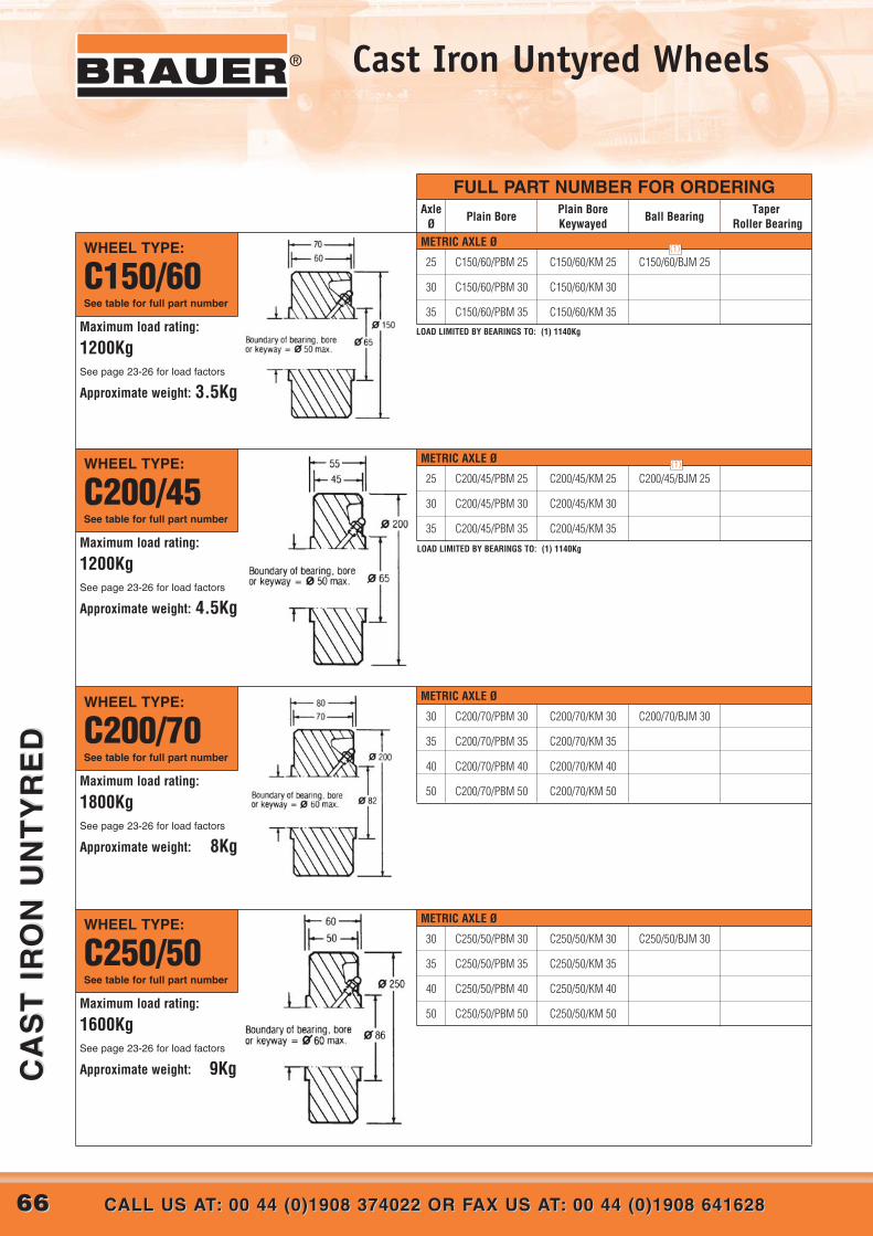
6666 CALL US AT: 00 44 (0)1908 374022 OR FAX US AT: 00 44 (0)1908 641628CALL US AT: 00 44 (0)1908 374022 OR FAX US AT: 00 44 (0)1908 641628
CA
ST
IR
ON
UN
TY
RE
DC
AS
T I
RO
N U
NT
YR
ED
® Cast Iron Untyred Wheels
METRIC AXLE Ø
METRIC AXLE Ø
METRIC AXLE Ø
FULL PART NUMBER FOR ORDERINGAxle
ØPlain Bore
Plain Bore Keywayed
Ball BearingTaper
Roller Bearing
WHEEL TYPE:
C150/60See table for full part number
Maximum load rating:
1200KgSee page 23-26 for load factors
Approximate weight: 3.5Kg
WHEEL TYPE:
C200/45See table for full part number
Maximum load rating:
1200KgSee page 23-26 for load factors
Approximate weight: 4.5Kg
25
30
35
C150/60/PBM 25
C150/60/PBM 30
C150/60/PBM 35
C150/60/KM 25
C150/60/KM 30
C150/60/KM 35
C150/60/BJM 25
25
30
35
C200/45/PBM 25
C200/45/PBM 30
C200/45/PBM 35
C200/45/KM 25
C200/45/KM 30
C200/45/KM 35
C200/45/BJM 25
WHEEL TYPE:
C200/70See table for full part number
Maximum load rating:
1800KgSee page 23-26 for load factors
Approximate weight: 8Kg
30
35
40
50
C200/70/PBM 30
C200/70/PBM 35
C200/70/PBM 40
C200/70/PBM 50
C200/70/KM 30
C200/70/KM 35
C200/70/KM 40
C200/70/KM 50
C200/70/BJM 30
WHEEL TYPE:
C250/50See table for full part number
Maximum load rating:
1600KgSee page 23-26 for load factors
Approximate weight: 9Kg
30
35
40
50
C250/50/PBM 30
C250/50/PBM 35
C250/50/PBM 40
C250/50/PBM 50
C250/50/KM 30
C250/50/KM 35
C250/50/KM 40
C250/50/KM 50
C250/50/BJM 30
METRIC AXLE Ø
(1)
(1)
LOAD LIMITED BY BEARINGS TO: (1) 1140Kg
LOAD LIMITED BY BEARINGS TO: (1) 1140Kg
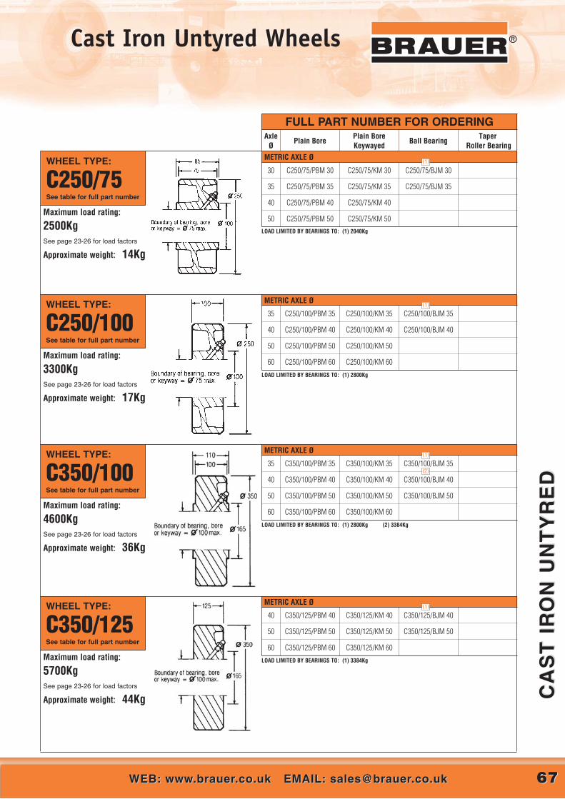
6767WEB: www.brauer.co.uk EMAIL: [email protected]: www.brauer.co.uk EMAIL: [email protected]
CA
ST
IR
ON
UN
TY
RE
DC
AS
T I
RO
N U
NT
YR
ED
®Cast Iron Untyred Wheels
WHEEL TYPE:
C250/75See table for full part number
Maximum load rating:
2500KgSee page 23-26 for load factors
Approximate weight: 14Kg
30
35
40
50
C250/75/PBM 30
C250/75/PBM 35
C250/75/PBM 40
C250/75/PBM 50
C250/75/KM 30
C250/75/KM 35
C250/75/KM 40
C250/75/KM 50
C250/75/BJM 30
C250/75/BJM 35
WHEEL TYPE:
C250/100See table for full part number
Maximum load rating:
3300KgSee page 23-26 for load factors
Approximate weight: 17Kg
35
40
50
60
C250/100/PBM 35
C250/100/PBM 40
C250/100/PBM 50
C250/100/PBM 60
C250/100/KM 35
C250/100/KM 40
C250/100/KM 50
C250/100/KM 60
C250/100/BJM 35
C250/100/BJM 40
WHEEL TYPE:
C350/100See table for full part number
Maximum load rating:
4600KgSee page 23-26 for load factors
Approximate weight: 36Kg
35
40
50
60
C350/100/PBM 35
C350/100/PBM 40
C350/100/PBM 50
C350/100/PBM 60
C350/100/KM 35
C350/100/KM 40
C350/100/KM 50
C350/100/KM 60
C350/100/BJM 35
C350/100/BJM 40
C350/100/BJM 50
WHEEL TYPE:
C350/125See table for full part number
Maximum load rating:
5700KgSee page 23-26 for load factors
Approximate weight: 44Kg
40
50
60
C350/125/PBM 40
C350/125/PBM 50
C350/125/PBM 60
C350/125/KM 40
C350/125/KM 50
C350/125/KM 60
C350/125/BJM 40
C350/125/BJM 50
(2)
LOAD LIMITED BY BEARINGS TO: (1) 2800Kg
LOAD LIMITED BY BEARINGS TO: (1) 2800Kg (2) 3384Kg
LOAD LIMITED BY BEARINGS TO: (1) 3384Kg
METRIC AXLE Ø
METRIC AXLE Ø
METRIC AXLE Ø
METRIC AXLE Ø
(1)
(1)
(1)
FULL PART NUMBER FOR ORDERINGAxle
ØPlain Bore
Plain Bore Keywayed
Ball BearingTaper
Roller Bearing
(1)
LOAD LIMITED BY BEARINGS TO: (1) 2040Kg

For technical information covering load factors, chemicalresistance, inertial and rolling resistance, coefficients offriction between wheel and surface, and keywaydimensions, see “Design Data” Index on page 20.
Drawings show grease nipple but standard wheels do notcome with grease nipple unless specifically requested.
Tyres can be produced with crown/dome treads to suit specific applications.
ALLOWABLE LOADS @ 6KPH
Brauer HEAVITHANE™ Polyurethane is resilient, durable material, resistant toabrasion and to many common chemicals. Polyurethane tyred wheels arecapable of carrying heavy loads and of transmitting driving forces.
MATERIAL: Wheel centre – cast iron to BS1452: 1977: Grade 200 or steel toBS970: Part 1: 1983: 080M4O. Tyre – Polyester based polymer of 92˚± 3˚ A Shore hardness.
OPERATING TEMPERATURE RANGE:-20˚C to +60˚C (115˚C for limited use)
PLEASE SPECIFY IF OPERATING IN HIGH HUMIDITY.Anti-hydrolysis polyurethane is recommended for use in an operatingenvironment of high humidity.
Polyurethane to the above hardness used on these wheels is Vulkollan, ahigh quality material that provides superior performance in mostapplications.
Should the mechanical properties of standard Vulkollan be inappropriatefor the application, alternative grades of Polyurethane can be producedto meet the requirements. Polyurethane can be bonded onto most metalcentres including aluminium, titanium, stainless steel and various ferrousand non-ferrous alloys.
The ‘maximum load rating’ given for each wheel is for operation underideal conditions. Load factors must be applied according to theanticipated working conditions – see ‘Design Data’ para. 5.1.
For wheels of larger diameter or greater load capacity see the PH series onpages 81-84. Alternative bore/bearing diameters and alternative bearingtypes (i.e. bronze bushes, self-lubricating bushes, roller bearings, sphericalroller bearings, etc.) are available to order – see page 26-27.
METRIC AXLE Ø
METRIC AXLE Ø
FULL PART NUMBER FOR ORDERING
WHEEL TYPE:
H75/35See table for full part number
AxleØ
Plain BorePlain Bore Keywayed
Ball BearingTaper
Roller Bearing
12
20
25
30
H75/35/PBM 12
H75/35/PBM 20
H75/35/PBM 25
H75/35/PBM 30
H75/35/KM 12
H75/35/KM 20
H75/35/KM 25
H75/35/KM 30
H75/35/BJM 12
H75/35/BJM 20
Maximum load rating:
300KgSee page 22 for load factors
Approximate weight: 0.5Kg
WHEEL TYPE:
H85/75See table for full part number
20 N/A H85/75/BJM 20
Maximum load rating:
700KgSee page 22 for load factors
Approximate weight: 0.6KgWheels fitted with ball journals are pre-lubricated, double shielded
Wheels fitted with ball journals are pre-lubricated, double shielded
®
PO
LYU
RE
TH
AN
E T
YR
ED
PO
LYU
RE
TH
AN
E T
YR
ED
CALL US AT: 00 44 (0)1908 374022 OR FAX US AT: 00 44 (0)1908 641628CALL US AT: 00 44 (0)1908 374022 OR FAX US AT: 00 44 (0)1908 6416286868
Polyurethane Tyred Wheels
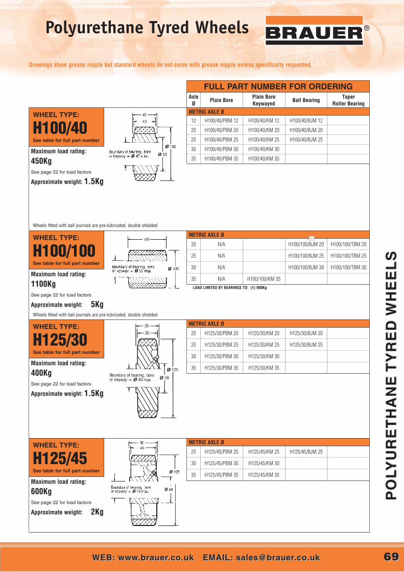
6969WEB: www.brauer.co.uk EMAIL: [email protected]: www.brauer.co.uk EMAIL: [email protected]
PO
LYU
RE
TH
AN
E T
YR
ED
WH
EE
LS
PO
LYU
RE
TH
AN
E T
YR
ED
WH
EE
LS
®Polyurethane Tyred Wheels
FULL PART NUMBER FOR ORDERINGAxle
ØPlain Bore
Plain Bore Keywayed
Ball BearingTaper
Roller BearingMETRIC AXLE Ø
METRIC AXLE Ø
METRIC AXLE Ø
METRIC AXLE Ø
WHEEL TYPE:
H100/100See table for full part number
20
25
30
35
N/A
N/A
N/A
N/A H100/100/KM 35
H100/100/BJM 20
H100/100/BJM 25
H100/100/BJM 30
H100/100/TBM 20
H100/100/TBM 25
H100/100/TBM 30
20
25
30
35
H125/30/PBM 20
H125/30/PBM 25
H125/30/PBM 30
H125/30/PBM 35
H125/30/KM 20
H125/30/KM 25
H125/30/KM 30
H125/30/KM 35
H125/30/BJM 20
H125/30/BJM 25
25
30
35
H125/45/PBM 25
H125/45/PBM 30
H125/45/PBM 35
H125/45/KM 25
H125/45/KM 30
H125/45/KM 35
H125/45/BJM 25
Maximum load rating:
1100KgSee page 22 for load factors
Approximate weight: 5Kg
WHEEL TYPE:
H125/30See table for full part number
Maximum load rating:
400KgSee page 22 for load factors
Approximate weight: 1.5Kg
WHEEL TYPE:
H125/45See table for full part number
Maximum load rating:
600KgSee page 22 for load factors
Approximate weight: 2Kg
Wheels fitted with ball journals are pre-lubricated, double shielded
WHEEL TYPE:
H100/40See table for full part number
12
20
25
30
35
H100/40/PBM 12
H100/40/PBM 20
H100/40/PBM 25
H100/40/PBM 30
H100/40/PBM 35
H100/40/KM 12
H100/40/KM 20
H100/40/KM 25
H100/40/KM 30
H100/40/KM 35
H100/40/BJM 12
H100/40/BJM 20
H100/40/BJM 25
Maximum load rating:
450KgSee page 22 for load factors
Approximate weight: 1.5Kg
Wheels fitted with ball journals are pre-lubricated, double shielded
(1)
LOAD LIMITED BY BEARINGS TO: (1) 900Kg
Drawings show grease nipple but standard wheels do not come with grease nipple unless specifically requested.

7070 CALL US AT: 00 44 (0)1908 374022 OR FAX US AT: 00 44 (0)1908 641628CALL US AT: 00 44 (0)1908 374022 OR FAX US AT: 00 44 (0)1908 641628
PO
LYU
RE
TH
AN
E T
YR
ED
WH
EE
LS
PO
LYU
RE
TH
AN
E T
YR
ED
WH
EE
LS
® Polyurethane Tyred Wheels
METRIC AXLE Ø
FULL PART NUMBER FOR ORDERINGAxle
ØPlain Bore
Plain Bore Keywayed
Ball BearingTaper
Roller Bearing
20
25
30
H150/35/PBM 20
H150/35/PBM 25
H150/35/PBM 30
H150/35/KM 20
H150/35/KM 25
H150/35/KM 30
H150/35/BJM 20
H150/35/BJM 25
WHEEL TYPE:
H150/35See table for full part number
Maximum load rating:
600KgSee page 22 for load factors
Approximate weight: 2Kg
WHEEL TYPE:
H150/150See table for full part number
25
30
35
40
H200/40/PBM 25
H200/40/PBM 30
H200/40/PBM 35
H200/40/PBM 40
H200/40/KM 25
H200/40/KM 30
H200/40/KM 35
H200/40/KM 40
H200/40/BJM 25
H200/40/BJM 30
H200/40/TBM 25
H200/40/TBM 30
25
30
35
N/A
N/A
N/A H150/150/KM 35
H150/150/BJM 25
H150/150/BJM 30
H150/150/BJM 35
H150/150/TBM 25
H150/150/TBM 30
H150/150/TBM 35Maximum load rating:
2300KgSee page 22 for load factors
Approximate weight: 7Kg
WHEEL TYPE:
H200/40See table for full part number
Maximum load rating:
900KgSee page 22 for load factors
Approximate weight: 4Kg
Wheels fitted with ball journals are pre-lubricated, double shielded
25
30
35
H150/50/PBM 25
H150/50/PBM 30
H150/50/PBM 35
H150/50/KM 25
H150/50/KM 30
H150/50/KM 35
H150/50/BJM 25 H150/50/TBM 25WHEEL TYPE:
H150/50See table for full part number
Maximum load rating:
900KgSee page 22 for load factors
Approximate weight: 3Kg
METRIC AXLE Ø
METRIC AXLE Ø
METRIC AXLE Ø
LOAD LIMITED BY BEARINGS TO: (1) 1140kg (2) 2040Kg
(1)
(2)

7171WEB: www.brauer.co.uk EMAIL: [email protected]: www.brauer.co.uk EMAIL: [email protected]
PO
LYU
RE
TH
AN
E T
YR
ED
WH
EE
LS
PO
LYU
RE
TH
AN
E T
YR
ED
WH
EE
LS
®Polyurethane Tyred Wheels
FULL PART NUMBER FOR ORDERINGAxle
ØPlain Bore
Plain Bore Keywayed
Ball BearingTaper
Roller Bearing
30
35
40
H200/60/PBM 30
H200/60/PBM 35
H200/60/PBM 40
H200/60/KM 30
H200/60/KM 35
H200/60/KM 40
H200/60/BJM 30 H200/60/TBM 30
H200/60/TBM 35
30
35
40
H250/45/PBM 30
H250/45/PBM 35
H250/45/PBM 40
H250/45/KM 30
H250/45/KM 35
H250/45/KM 40
H250/45/BJM 30 H250/45/TBM 30
H250/45/TBM 35
WHEEL TYPE:
H200/60See table for full part number
Maximum load rating:
1400KgSee page 22 for load factors
Approximate weight: 7Kg
WHEEL TYPE:
H250/45See table for full part number
Maximum load rating:
1300KgSee page 22 for load factors
Approximate weight: 7Kg
WHEEL TYPE:
H250/70See table for full part number
Maximum load rating:
2000KgSee page 22 for load factors
Approximate weight: 12Kg
30
35
40
50
H250/70/PBM 30
H250/70/PBM 35
H250/70/PBM 40
H250/70/PBM 50
H250/70/KM 30
H250/70/KM 35
H250/70/KM 40
H250/70/KM 50
H250/70/BJM 30
H250/70/BJM 35
H250/70/TBM 30
H250/70/TBM 35
25
30
35
40
H200/75/KM 25
H200/75/KM 30
H200/75/KM 35
H200/75/KM 40
H200/75/BJM 25
H200/75/BJM 30
H200/75/TBM 25
H200/75/TBM 30
WHEEL TYPE:
H200/75See table for full part number
Maximum load rating:
1750KgSee page 22 for load factors
Approximate weight:14.4Kg
LOAD LIMITED BY BEARINGS TO: (1) 1140Kg
METRIC AXLE Ø
METRIC AXLE Ø
METRIC AXLE Ø
METRIC AXLE Ø (1)

7272 CALL US AT: 00 44 (0)1908 374022 OR FAX US AT: 00 44 (0)1908 641628CALL US AT: 00 44 (0)1908 374022 OR FAX US AT: 00 44 (0)1908 641628
PO
LYU
RE
TH
AN
E T
YR
ED
WH
EE
LS
PO
LYU
RE
TH
AN
E T
YR
ED
WH
EE
LS
® Polyurethane Tyred Wheels
FULL PART NUMBER FOR ORDERING
WHEEL TYPE:
H300/50See table for full part number
AxleØ
Plain BorePlain Bore Keywayed
Ball BearingTaper
Roller Bearing
30
35
40
50
H300/50/PBM 30
H300/50/PBM 35
H300/50/PBM 40
H300/50/PBM 50
H300/50/KM 30
H300/50/KM 35
H300/50/KM 40
H300/50/KM 50
H300/50/BJM 30
H300/50/BJM 35
H300/50/TBM 30
H300/50/TBM 35
35
40
50
60
H300/75/PBM 35
H300/75/PBM 40
H300/75/PBM 50
H300/75/PBM 60
H300/75/KM 35
H300/75/KM 40
H300/75/KM 50
H300/75/KM 60
H300/75/BJM 35
H300/75/BJM 40
H300/75/TBM 35
H300/75/TBM 40
40
50
60
H300/100/PBM 40
H300/100/PBM 50
H300/100/PBM 60
H300/100/KM 40
H300/100/KM 50
H300/100/KM 60
H300/100/BJM 40
H300/100/BJM 50
H300/100/TBM 40
H300/100/TBM 50
Maximum load rating:
1500KgSee page 22 for load factors
Approximate weight: 10Kg
WHEEL TYPE:
H300/75See table for full part number
Maximum load rating:
2300KgSee page 22 for load factors
Approximate weight: 16Kg
WHEEL TYPE:
H300/100See table for full part number
Maximum load rating:
3100KgSee page 22 for load factors
Approximate weight: 18Kg
METRIC AXLE Ø
METRIC AXLE Ø
METRIC AXLE Ø
WHEEL TYPE:
H250/97.5See table for full part number
40
50
H250/97.5/PBM 40
H250/97.5/PBM 50
H250/97.5/KM 40
H250/97.5/KM 50
H250/97.5/BJM 40
H250/97.5/BJM 50
H250/97.5/TBM 40
H2500/97.5/TBM 50
Maximum load rating:
2700KgSee page 22 for load factors
Approximate weight: 19.5Kg
METRIC AXLE Ø
Wheels fitted with ball journals are pre-lubricated, double shielded

7373WEB: www.brauer.co.uk EMAIL: [email protected]: www.brauer.co.uk EMAIL: [email protected]
PO
LYU
RE
TH
AN
E T
YR
ED
WH
EE
LS
PO
LYU
RE
TH
AN
E T
YR
ED
WH
EE
LS
®Polyurethane Tyred Wheels
FULL PART NUMBER FOR ORDERINGAxle
ØPlain Bore
Plain Bore Keywayed
Ball BearingTaper
Roller Bearing
50
60
75
H400/100/PBM 50
H400/100/PBM 60
H400/100/PBM 75
H400/100/KM 50
H400/100/KM 60
H400/100/KM 75
H400/100/BJM 50
H400/100/BJM 60
H400/100/BJM 75
H400/100/TBM 50
H400/100/TBM 60
H400/100/TBM 75
WHEEL TYPE:
H400/100See table for full part number
Maximum load rating:
4200KgSee page 22 for load factors
Approximate weight: 39.5Kg
50
60
75
H400/125/PBM 50
H400/125/PBM 60
H400/125/PBM 75
H400/125/KM 50
H400/125/KM 60
H400/125/KM 75
H400/125/BJM 50
H400/125/BJM 60
H400/125/BJM 75
H400/125/TBM 50
H400/125/TBM 60
H400/125/TBM 75
WHEEL TYPE:
H400/125See table for full part number
Maximum load rating:
5200KgSee page 22 for load factors
Approximate weight: 48.5Kg
METRIC AXLE Ø
METRIC AXLE Ø
50
60
75
H460/75/PBM 50
H460/75/PBM 60
H460/75/KM 50
H460/75/KM 60
H460/75/BJM 50
H460/75/BJM 60
H460/75/BJM 75
H460/75/TBM 60
H460/75/TBM 75
WHEEL TYPE:
H460/75See table for full part number
Maximum load rating:
3500KgSee page 22 for load factors
Approximate weight: 40Kg
METRIC AXLE Ø
40
50
60
H350/100/KM 40
H350/100/KM 50
H350/100/KM 60
H350/100/BJM 40
H350/100/BJM 50
H350/100/BJM 60
H350/100/TBM 40
H350/100/TBM 50
H350/100/TBM 60
WHEEL TYPE:
H350/100See table for full part number
Maximum load rating:
3600KgSee page 22 for load factors
Approximate weight: 52Kg
METRIC AXLE Ø
LOAD LIMITED BY BEARINGS TO: (1) 3384Kg
(1)

MANUFACTURER MODEL NUMBER WHEEL SIZE
ATLET
75133 150 X 55
78120 250 x 75
72711 350 x 40
BT (Rola Truck)
134698 125 x 40
171999 125 x 50
156259 125 x 50
46106 140 x 60
171029 150 x 50
129920 215 x 70
135161 250 x 105
137586 300 x 100
143163 300 x 100
151991 310 x 120
162602 350 x 127
7474 CALL US AT: 00 44 (0)1908 374022 OR FAX US AT: 00 44 (0)1908 641628CALL US AT: 00 44 (0)1908 374022 OR FAX US AT: 00 44 (0)1908 641628
MA
TE
RIA
L H
AN
DL
ING
TR
UC
K W
HE
EL
SM
AT
ER
IAL
HA
ND
LIN
G T
RU
CK
WH
EE
LS
® Material Handling TruckWheels
MANUFACTURER MODEL NUMBER WHEEL SIZE
JUNGHEINRICH
50019777 140 X 54
27634500 150 x 54
63210590 230 x 65
63215600 230 x 78
50052398 285 x 100
50030509 343 x 114
63145890 343 x 140
STILL WAGNER
426413 125 x 50
412343 150 x 50
359920 230 x 75
365234 343 x 136
422980 400 x 160
LANSING-LINDE
0009933803 125 x 60
0029903807 285 x 100
9815000599 330 x 135

7575WEB: www.brauer.co.uk EMAIL: [email protected]: www.brauer.co.uk EMAIL: [email protected]
VU
LK
OL
LA
N 9
0 G
UID
E R
OL
LE
RS
VU
LK
OL
LA
N 9
0 G
UID
E R
OL
LE
RS
®Vulkollan 90 Guide Rollers
NAME VULKOLLAN 90ABBREVIATION VK90COLOUR NATURALHARDNESS 92/37 DIN 53505STRESS AT 100% STRAIN 8.6 DIN 53504STRESS AT 300% STRAIN 18.8 DIN 53504TENSILE STRENGTH 42 DIN 53504ELONGATION AT BREAK 650 DIN 53504TEAR PROPAGATION RESISTANCE 58 DIN 53515REBOUND 55 DIN 53512ABRASION RESISTANCE 42 DIN 53516DENSITY 1.26 DIN 53479
COMPRESSION SET %12
20
DIN 53517
Temperature range of operation -40° to +85°C. The polyuret hane is non-marking, with highresistance to axial loading, and runs quietly. Used in conveyor applications, systems of transporting products along material handling systems or in areas of support for hanging structures or components, as found in;
• escalators• sorting• overhead conveyors• conveyors for letter & mail• baggage handling airport equipment
Higher load capacity than Vulkopan, due to the chemical bonding and therefore far more resistant toaxial forces. 92º shore hardness guarantees higher levels of elasticity and damping & improvedtraction. Finally, Vulkollan unlike Vulkopan can be machined after setting for specific tolerancing.
SHORE A/DMPaMPaMPa%kN/m%mm3
g/cm3
70 h / 23ºC70 h / 73.5ºF
24 h / 70ºC24 h / 158ºF

7676 CALL US AT: 00 44 (0)1908 374022 OR FAX US AT: 00 44 (0)1908 641628CALL US AT: 00 44 (0)1908 374022 OR FAX US AT: 00 44 (0)1908 641628
VU
LK
OL
LA
N 9
0 G
UID
E R
OL
LE
RS
VU
LK
OL
LA
N 9
0 G
UID
E R
OL
LE
RS
® Vulkollan 90 Guide Rollers
VK RK 035 011 008 S 35 11 8 608-2RS 50
VK RK 040 012 010 ZVK RK 040 015 010 SVK RK 040 015 010 ZVK RK 040 016 012 ZVK RK 040 025 010 Z
4040404040
1215151625
1010101210
6000-ZZ6000-2RS6000-ZZ6001-ZZ6000-ZZ
6060606060
VK RK 045 015 015VK RK 045 038 010 S
4545
1538
1510
61902-ZZ6200-2RS
7070
VK RK 050 015 010 SVK RK 050 015 012 SAVK RK 050 015 012 ZVK RK 050 015 015 ZVK RK 050 018 012 ZVK RK 050 018 017 SVK RK 050 018 020 ZVK RK 050 020 010 SBVK RK 050 020 012 SVK RK 050 020 012 ZBVK RK 050 020 017 ZVK RK 050 025 010 ZVK RK 050 025 012 S
50505050505050505050505050
15151515181818202020202525
10121215121720101212171012
6000-2RS6001-2RS6001-ZZ6001-ZZ6201-ZZ
6003-2RS61804-ZZ6200-2RS6201-2RS6201-ZZ6003-ZZ6200-ZZ
6201-2RS
85858585959595
100100100100105105
VK RK 055 020 012 SVK RK 055 020 015 S
5555
2020
1215
6201-2RS6002-2RS
105105
VK RK 060 014 010 ZBVK RK 060 016 015 ZBVK RK 060 017 012 SBVK RK 060 018 017 SAVK RK 060 018 017 ZAVK RK 060 020 017 SAVK RK 060 020 017 SBVK RK 060 020 017 SKVK RK 060 020 017 ZBVK RK 060 020 020 SAVK RK 060 020 017 ZAVK RK 060 025 015 ZDVK RK 060 025 017 ZVK RK 060 025 020
6060606060606060606060606060
1416171818202020202020252525
1015121717171717172020151720
6200-ZZ6202-ZZ
6201-2RS6003-2RS6003-ZZ
6003-2RS6203-2RS6203-2RS6203-ZZ
6004-2RS6004-ZZ6002-ZZ6003-ZZ6004-ZZ
110110110110110120120120120120120125125125
6
VK RK 065 016 020 S 65 16 20 6004-2RS 125
VK RK 070 020 020 SBVK RK 070 020 020 ZBVK RK 070 020 020 ZCVK RK 070 025 020 SVK RK 070 025 020 ZVK RK 070 025 020 ZCVK RK 070 025 025 SVK RK 070 025 025 Z
7070707070707070
2020252525252525
2020172020202525
6204-2RS6204-ZZ6303-ZZ
6204-2RS6204-ZZ6304-ZZ
6205-2RS6005-ZZ
130130150150150150150150
VK RK 080 020 017 ZVK RK 080 020 020 ZVK RK 080 020 025 ZBVK RK 080 025 020 SAVK RK 080 025 025 SVK RK 080 025 025 ZVK RK 080 030 020 SVK RK 080 030 020 Z
8080808080808080
2020202525253030
1720252025252020
6303-ZZ6304-ZZ6205-ZZ
6004-2RS6205-2RS6205-ZZ
6204-2RS6204-ZZ
150150150170170170180180
VK RK 090 020 025 SBVK RK 090 025 025 ZVK RK 090 035 020 Z
909090
202535
252520
6205-2RS6005-ZZ6304-ZZ
170190200
VK RK 100 020 025 SVK RK 100 020 025 ZBVK RK 100 025 020 ZVK RK 100 025 025 ZBVK RK 100 028 020 SVK RK 100 030 020 ZCVK RK 100 030 025 SVK RK 100 030 025 ZB
100100100100100100100100
2020202528303030
2525202520202525
6205-2RS6205-ZZ6204-ZZ6205-ZZ
6204-2RS6304-ZZ
6205-2RS6205-ZZ
190190210210215220220220
VK RK 120 025 025 ZVK RK 120 030 030 S
120120
2530
2530
6205-ZZ6206-2RS
250260
VK RK 125 025 025 ZVK RK 125 030 025 SVK RK 125 030 025 ZBVK RK 125 030 030 RVK RK 125 030 030 Z
125125125125125
2530303030
2525253030
6205-ZZ6205-2RS6205-ZZ
6206-2RS6306-ZZ
260260260260260
6
‘VK’ GUIDE ROLLER TECHNICAL INFORMATIONPolyuret hane 92° Shore A: Hardness
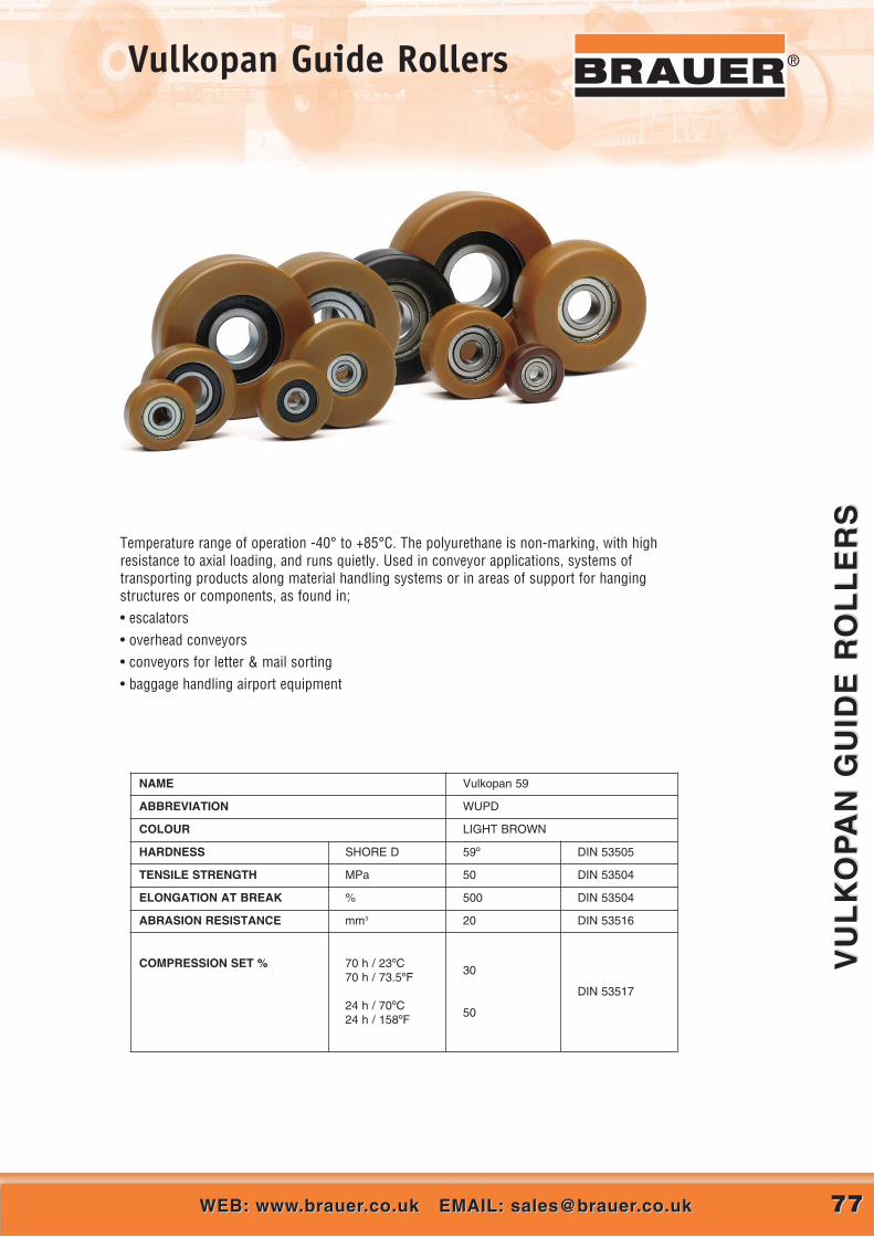
7777WEB: www.brauer.co.uk EMAIL: [email protected]: www.brauer.co.uk EMAIL: [email protected]
VU
LK
OP
AN
GU
IDE
RO
LL
ER
SV
UL
KO
PA
N G
UID
E R
OL
LE
RS
®Vulkopan Guide Rollers
Temperature range of operation -40° to +85°C. The polyuret hane is non-marking, with highresistance to axial loading, and runs quietly. Used in conveyor applications, systems of transporting products along material handling systems or in areas of support for hanging structures or components, as found in;• escalators• overhead conveyors• conveyors for letter & mail sorting• baggage handling airport equipment
NAME Vulkopan 59
ABBREVIATION WUPD
COLOUR LIGHT BROWN
HARDNESS SHORE D 59º DIN 53505
TENSILE STRENGTH MPa 50 DIN 53504
ELONGATION AT BREAK % 500 DIN 53504
ABRASION RESISTANCE mm3 20 DIN 53516
COMPRESSION SET % 70 h / 23ºC70 h / 73.5ºF
24 h / 70ºC24 h / 158ºF
30
50
DIN 53517

7878 CALL US AT: 00 44 (0)1908 374022 OR FAX US AT: 00 44 (0)1908 641628CALL US AT: 00 44 (0)1908 374022 OR FAX US AT: 00 44 (0)1908 641628
VU
LK
OP
AN
GU
IDE
RO
LL
ER
SV
UL
KO
PA
N G
UID
E R
OL
LE
RS
® Vulkopan Guide Rollers
WU DP 018 006 004 18 6 4 684 ZZ 10
WU DP 022 010 004 22 10 4 684 ZZ 20WU DP 025 010 006 SWU DP 025 010 006 Z
2525
1010
66
626 2RS626 ZZ
2020
WU DP 026 012 006 Z 26 12 6 626 ZZ 25
WU DP 030 011 008 SWU DP 030 011 008 ZWU DP 030 011 009 SWU DP 030 011 009 Z
30303030
11111111
8899
608 2RS608 ZZ
609 2RS609 ZZ
30302020
WU DP 032 016 008 SWU DP 032 016 008 Z
3232
1616
88
608 2RS608 ZZ
4545
WU DP 035 009 006 SWU DP 035 011 008 SWU DP 035 011 008 ZWU DP 035 015 010 Z
35353535
9111115
688
10
626 2RS608 2RS608 ZZ
6000 ZZ
40404060
WU DP 040 014 010 SWU DP 040 014 010 ZWU DP 040 014 012 ZWU DP 040 020 010 SWU DP 040 020 010 ZWU DP 040 025 010 Z
404040404040
141414202025
101012101010
6200 2RS6200 ZZ6001 ZZ
6200 2RS6200 ZZ
2X6000 ZZ
7070709090
110WU DP 042 014 015 S 42 14 15 6002 2RS 80WU DP 044 012 012 ZWU DP 044 016 012 Z
4444
1216
1212
6001 ZZ6001 ZZ
6080
WU DP 045 013 012 ZWU DP 045 012 012 Z
4545
1315
1212
6001 ZZ6001 ZZ
8080
WU DP 047 013 012 Z 48 13 12 6001 ZZ 80
WU DP 049 015 010 Z 49 15 10 6200 ZZ 80WU DP 050 012 015 ZWU DP 050 015 008 SWU DP 050 015 008 ZWU DP 050 015 010 SWU DP 050 015 010 ZWU DP 050 015 012 SWU DP 050 015 012 ZWU DP 050 018 010 ZWU DP 050 018 012 SWU DP 050 018 012 ZWU DP 050 018 015 SWU DP 050 018 015 ZWU DP 050 018 017 SWU DP 050 018 017 ZWU DP 050 025 012 SWU DP 050 025 012 ZWU DP 050 025 015 Z
5050505050505050505050505050505050
1215151515151518181818181818252525
1588
1010121210121215151717121215
6002 ZZ608 2RS608 ZZ
6200 2RS6200 ZZ
6201 2RS6201 ZZ6200 ZZ
6201 2RS6201 ZZ
6202 2RS6202 ZZ
6003 2RS6003 ZZ
6201 2RS6201 ZZ6202 ZZ
708080
100100100100100100100110110110110125125115
6
WU DP 053 020 017 S 53 20 17 6203 2RS 75
WU DP 055 020 012 ZWU DP 055 024 020 SWU DP 055 024 020 Z
555555
202424
122020
6201 ZZ6204 2RS6204 ZZ
1158O80
WU DP 057 020 017 SWU DP 057 020 017 Z
5757
2020
1717
6203 2RS6203 ZZ
135135
WU DP 060 020 017 SWU DP 060 020 017 ZWU DP 060 020 020 SWU DP 060 020 020 ZWU DP 060 025 015 SWU DP 060 025 015 ZWU DP 060 025 020 Z
60606060606060
20202020252525
17172020151520
6203 2RS6203 ZZ
6004 2RS6004 ZZ
6202 SRS6202 ZZ6004 ZZ
150150150150150150150
WU DP 062 020 017 ZWU DP 062 021 025 Z
6262
2021
1725
6203 ZZ6205 ZZ
160180
WU DP 063 020 017 Z 63 20 17 6203 ZZ 160
WU DP 064 018 017 ZWU DP 064 020 017 Z
6464
1820
1717
6203 ZZ6203 ZZ
150150
WU DP 065 025 020 SWU DP 065 025 020 Z
6565
2525
2020
6204 2RS6204 ZZ
150150
WU DP 070 017 017 ZWU DP 070 025 020 SWU DP 070 025 020 ZWU DP 070 035 020 Z
70707070
17252535
17202020
6203 ZZ6204 2RS6204 ZZ6204 ZZ
100200200220
WU DP 073 025 020 SWU DP 073 025 020 Z
7373
2525
2020
6204 2RS6204 ZZ
210210
WU DP 075 020 017 SWU DP 075 020 017 ZWU DP 075 021 020 SWU DP 075 021 020 Z
75757575
20202121
17172020
6303 2RS6303 ZZ
6204 2RS6204 ZZ
160160160160
WU DP 080 020 017 ZWU DP 080 025 025 SWU DP 080 025 025 Z
808080
202525
172525
6303 ZZ6205 2RS6205 ZZ
175215215
WU DP 085 025 020 Z 85 25 20 6304 ZZ 175
WU DP 090 020 017 ZWU DP 090 020 025 Z
9090
2020
1725
6303 ZZ6205 ZZ
195190
WU DP 095 020 017 Z 95 20 17 6303 ZZ 170
WU DP 100 025 025 Z 100 25 25 6205 ZZ 260
6
‘WU’ GUIDE ROLLER TECHNICAL INFORMATIONPolyuret hane 59° Shore D: Hardness

7979WEB: www.brauer.co.uk EMAIL: [email protected]: www.brauer.co.uk EMAIL: [email protected]
VU
LK
OL
LA
N C
VU
LK
OL
LA
N C
®Vulkollan CElectrical Conductive Wheels
NAME VULKOLLAN C
ABBREVIATION VKC
COLOUR Black
HARDNESS SHORE A/D 92/37 DIN 53505
STRESS AT 100% STRAIN MPa 8.6 DIN 53504
STRESS AT 300% STRAIN MPa 18.8 DIN 53504
TENSILE STRENGTH MPa 42 DIN 53504
ELONGATION AT BREAK % 650 DIN 53504
TEAR PROPAGATION RESISTANCE kN/m 58 DIN 53515
REBOUND % 55 DIN 53512
ABRASION RESISTANCE mm3 42 DIN 53516
DENSITY g/cm3 1.27 DIN 53479
COMPRESSION SET % 70 h / 23ºC70 h / 73.5ºF
24 h / 70ºC24 h / 158ºF
12
20
DIN 53517
Brauer (conductive) is a new product in the Brauer range ofwheels which are electrically conductive. This materialcorresponds to all the qualifications of the standards EN12527 toEN12533 and ISO 2878.
Regarding industrial wheels these standards indicate that an‘antistatic’ wheel has a resistance between 10^5 and 10^7 Ohm.When the electrical resistance is smaller than or equal to 10^4Ohm it may be called ‘electrically conductive’.
Brauer Conductive wheels have a resistance which isconsiderably lower than 10^4 Ohm, so these wheels may benamed electrically conductive.
They have the same advantages as the standard Vulkollan: veryhigh load capacity, high resistance to wear and tear, resistant tooil and grease etc.
The only available colour of the tread is black and the hardness isaround 92-95° shore A.
Vulkollan C is non-marking and the electrical characteristics donot change during the lifetime of the wheel.
As usual in the wheel industry for antistatic or electricallyconductive wheels all Vulkollan Conductive wheel centres will bepainted in black. The wheels are supplied with a yellow dot,which indicates that these wheels are electrically conductive.
Small series up to 15-20 pieces will be available in a shortdelivery time, bigger series are on request.
APPLICATION:
Environments with a higher danger of fire or explosion (eggas/dust)

CALL US AT: 00 44 (0)1908 374022 OR FAX US AT: 00 44 (0)1908 641628CALL US AT: 00 44 (0)1908 374022 OR FAX US AT: 00 44 (0)1908 6416288080
VU
LK
OL
LA
N C
VU
LK
OL
LA
N C
® Vulkollan CElectrical Conductive Wheels
APPLICATION INFORMATION FOR VULKOLLAN® C
Companies that stock, produce or distribute explosive or inflammable materials are very apprehensive of the dangers involved. Theconsequences of an ignition can be disastrous and could lead to the destruction of production facilities or even worse, the loss ofhuman life.These materials can be inflammable gas, fume, powder or dust. Mixed with oxygen they can cause an explosiveatmosphere.
This explosive atmosphere can be subdivided into 3 different zones:
• Zone 0: where the explosive atmosphere is continually present or for longer periods of time
• Zone 1: where the explosive atmosphere is present continuously or for longer periods of time
• Zone 3: where under normal circumstances there is no danger or only for a very short period
When the dangerous substances exist of powder or dust the zones are respectively called zone 20, 21, 22.
Possible sources of ignition:
1. For electrically driven vehicles:• sparks deriving from unprotected electrical components• hot surfaces such as braking discs• sparks deriving from static electricity or friction
2. For diesel driven vehicles:• flames or sparks from exhaust valves or pipes• flames or sparks from air inlets or vents• excessive speed or overloading• surface temperature of exhausts or other component such as brakes• sparks deriving from unprotected electrical components• sparks caused by discharge of static electricity or friction
European law has enacted some directives towards users and suppliers:
1. Companies using or manufacturing inflammable materials:This type of companies follow the Atex 1999/92/EC regulations also known as ATEX 137. These regulations premise theminimum requirements for safety and health protection for employees working in hazardous explosive environments.One of the obligations the employer has, is to provide the necessary equipment that comes under the exact category for thisrespective zone.• Zone 0 and 20: only equipment following Category 1• Zone 1 and 21: only equipment following Category 1 and 2• Zone 2 and 22: only equipment following Category 1, 2 and 3
2. Companies supplying equipment in explosive environments:This type of companies follow the Atex 94/9/EC regulations also known as ATEX 100a or 95.• Category 1: very high level of security• Category 2: high level of security• Category 3: standard level of securityThe category will be followed by a G (for gas, fume) or a D (for powder, dust) ex Cat 1 G: very high level of security forenvironments with gasificationSecured vehicles (category 1, 2 and 3) going faster than 6 km/h will be equipped with electrical conductive wheels.For slower vehicles a wire in contact with the floor will be sufficient.
Fields of application:
Oil and gas, refineries, aerosol, powders, plastics, chemicals, paint industry, glue, explosives, varnish, lacquer, pharmaceuticals,aircraft fuel, coatings & ink, food, aromatic compounds, alcohol, cosmetics, distilleries.
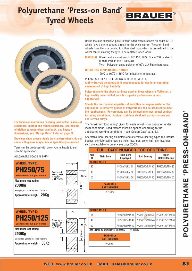
8181WEB: www.brauer.co.uk EMAIL: [email protected]: www.brauer.co.uk EMAIL: [email protected]
PO
LYU
RE
TH
AN
E ‘
PR
ES
S-O
N-B
AN
D’
PO
LYU
RE
TH
AN
E ‘
PR
ES
S-O
N-B
AN
D’
®Polyurethane ‘Press-on Band’Tyred Wheels
BAND ONLYPART NUMBER
PH250/5
BAND ONLYPART NUMBER
PH250/3
METRIC AXLE Ø
Unlike the less expensive polyurethane tyred wheels shown on pages 68-73which have the tyre bonded directly to the wheel centre, ‘Press-on Band’wheels have the tyre bonded to a thin steel band which is press-fitted to thewheel centre allowing the tyre to be replaced when worn.
MATERIAL: Wheel centre – cast iron to BS1452: 1977: Grade 200 or steel toBS970: Part 1: 1983: 080M4OTyre – Polyester based polymer of 92˚± 3˚A Shore hardness.
OPERATING TEMPERATURE RANGE:-20˚C to +60˚C (115˚C for limited intermittent use).
PLEASE SPECIFY IF OPERATING IN HIGH HUMIDITY.Anti-hydrolysis polyurethane is recommended for use in an operatingenvironment of high humidity.
Polyurethane to the above hardness used on these wheels is Vulkollan, ahigh quality material that provides superior performance in mostapplications.
Should the mechanical properties of Vulkollan be inappropriate for theapplication, alternative grades of Polyurethane can be produced to meetthe requirements. Polyurethane can be bonded onto most metal centresincluding aluminium, titanium, stainless steel and various ferrous andnon-ferrous alloys.
The ‘maximum load rating’ given for each wheel is for operation underideal conditions. Load factors must be applied according to theanticipated working conditions – see ‘Design Data’ para. 5.1.
Alternative bore/bearing diameters and alternative bearing types (i.e. bronzebushes, self-lubricating bushes, roller bearings, spherical roller bearings,etc.) are available to order – see page 26-27.
FULL PART NUMBER FOR ORDERING
WHEEL TYPE:
PH250/75See table for full part number
AxleØ
Plain BorePlain Bore Keywayed
Ball BearingTaper
Roller Bearing
35
40
50
PH250/75/KM 35
PH250/75/KM 40
PH250/75/KM 50
PH250/75/BJM 35
PH250/75/BJM 40
PH250/75/BJM 50
PH250/75/TBM 35
PH250/75/TBM 40
PH250/75/TBM 50Maximum load rating:
2000KgSee page 22-23 for load factors
Approximate weight: 20Kg
METRIC AXLE ØWHEEL TYPE:
PH250/125See table for full part number
35
40
50
PH250/125/KM 35
PH250/125/KM 40
PH250/125/KM 50
PH250/125/BJM 35
PH250/125/BJM 40
PH250/125/BJM 50
PH250/125/TBM 35
PH250/125/TBM 40
PH250/125/TBM 50Maximum load rating:
3400KgSee page 22-23 for load factors
Approximate weight: 33Kg
LOAD LIMITED BY BEARINGS TO: (1) 2800Kg (2) 3384Kg
(1)
(2)
For technical information covering load factors, chemicalresistance, inertial and rolling resistance, coefficientsof friction between wheel and track, and keywaydimensions, see “Design Data” Index on page 20.
Drawings show grease nipple but standard wheels do notcome with grease nipple unless specifically requested.
Tyres can be produced with crown/dome treads to suit specific applications.
ALLOWABLE LOADS @ 6KPH

8282 CALL US AT: 00 44 (0)1908 374022 OR FAX US AT: 00 44 (0)1908 641628CALL US AT: 00 44 (0)1908 374022 OR FAX US AT: 00 44 (0)1908 641628
PO
LYU
RE
TH
AN
E ‘
PR
ES
S-O
N-B
AN
D’
PO
LYU
RE
TH
AN
E ‘
PR
ES
S-O
N-B
AN
D’
® Polyurethane ‘Press-on Band’Tyred Wheels
PH380/4
BAND ONLYPART NUMBER
PH380/3
BAND ONLYPART NUMBER
PH300/4
BAND ONLYPART NUMBER
PH300/3
METRIC AXLE Ø
METRIC AXLE Ø
METRIC AXLE Ø
WHEEL TYPE:
PH300/75See table for full part number
WHEEL TYPE:
PH380/75See table for full part number
FULL PART NUMBER FOR ORDERINGAxle
ØPlain Bore
Plain Bore Keywayed
Ball BearingTaper
Roller Bearing
WHEEL TYPE:
PH380/100See table for full part number
60
75
PH380/100/KM 60
PH380/100/KM 75
PH380/100/BJM 60
PH380/100/BJM 75
PH380/100/TBM 60
PH380/100/TBM 75
Maximum load rating:
3600KgSee page 22-23 for load factors
Approximate weight: 45Kg
40
50
60
PH300/75/KM 40
PH300/75/KM 50
PH300/75/KM 60
PH300/75/BJM 40
PH300/75/BJM 50
PH300/75/BJM 60
PH300/75/TBM 40
PH300/75/TBM 50
PH300/75/TBM 60Maximum load rating:
2550kgSee page 22-23 for load factors
Approximate weight: 28kg
50
60
75
PH380/75/KM 50
PH380/75/KM 60
PH380/75/KM 75
PH380/75/BJM 50
PH380/75/BJM 60
PH380/75/BJM 75
PH380/75/TBM 50
PH380/75/TBM 60
PH380/75/TBM 75Maximum load rating:
2700KgSee page 22-23 for load factors
Approximate weight: 36Kg
METRIC AXLE Ø
50
60
PH350/100/KM 50
PH350/100/KM 60
PH350/100/BJM 50
PH350/100/BJM 60
PH350/100/TBM 50
PH350/100/TBM 60
WHEEL TYPE:
PH350/100See table for full part number
Maximum load rating:
3600KgSee page 22-23 for load factors
Approximate weight: 40Kg
BAND ONLYPART NUMBER

8383WEB: www.brauer.co.uk EMAIL: [email protected]: www.brauer.co.uk EMAIL: [email protected]
PO
LYU
RE
TH
AN
E ‘
PR
ES
S-O
N-B
AN
D’
PO
LYU
RE
TH
AN
E ‘
PR
ES
S-O
N-B
AN
D’
®Polyurethane ‘Press-on Band’Tyred Wheels
PH460/3
BAND ONLYPART NUMBER
PH400/5
BAND ONLYPART NUMBER
PH400/4
PH380/5
BAND ONLYPART NUMBER
FULL PART NUMBER FOR ORDERINGAxle
ØPlain Bore
Plain Bore Keywayed
Ball BearingTaper
Roller Bearing
METRIC AXLE ØWHEEL TYPE:
PH460/75See table for full part number
60
75
PH460/75/KM 60
PH460/75/KM 75
PH460/75/BJM 60
PH460/75/BJM 75
PH460/75/TBM 60
PH460/75/TBM 75
Maximum load rating:
3200KgSee page 22-23 for load factors
Approximate weight: 45Kg
METRIC AXLE ØWHEEL TYPE:
PH380/125See table for full part number
60
75
PH380/125/KM 60
PH380/125/KM 75
PH380/125/BJM 60
PH380/125/BJM 75
PH380/125/TBM 60
PH380/125/TBM 75
Maximum load rating:
4500KgSee page 22-23 for load factors
Approximate weight: 53Kg
METRIC AXLE ØWHEEL TYPE:
PH400/100See table for full part number
60
75
PH400/100/KM 60
PH400/100/KM 75
PH400/100/BJM 60
PH400/100/BJM 75
PH400/100/TBM 60
PH400/100/TBM 75
Maximum load rating:
3800KgSee page 22-23 for load factors
Approximate weight: 65Kg
METRIC AXLE ØWHEEL TYPE:
PH400/125See table for full part number
60
75
PH400/125/KM 60
PH400/125/KM 75
PH400/125/BJM 60
PH400/125/BJM 75
PH400/125/TBM 60
PH400/125/TBM 75
Maximum load rating:
4800KgSee page 22-23 for load factors
Approximate weight: 80Kg
BAND ONLYPART NUMBER

8484 CALL US AT: 00 44 (0)1908 374022 OR FAX US AT: 00 44 (0)1908 641628CALL US AT: 00 44 (0)1908 374022 OR FAX US AT: 00 44 (0)1908 641628
PO
LYU
RE
TH
AN
E ‘
PR
ES
S-O
N-B
AN
D’
PO
LYU
RE
TH
AN
E ‘
PR
ES
S-O
N-B
AN
D’
® Polyurethane ‘Press-on Band’Tyred Wheels
PH460/4
BAND ONLYPART NUMBER
PH500/3
BAND ONLYPART NUMBER
PH500/4
BAND ONLYPART NUMBER
METRIC AXLE Ø
METRIC AXLE Ø
METRIC AXLE ØWHEEL TYPE:
PH460/100See table for full part number
60
75
PH460/100/KM 60
PH460/100/KM 75
PH460/100/BJM 60
PH460/100/BJM 75
PH460/100/TBM 60
PH460/100/TBM 75
Maximum load rating:
4200KgSee page 22-23 for load factors
Approximate weight: 52Kg
WHEEL TYPE:
PH500/75See table for full part number
75
100
PH500/75/KM 75
PH500/75/KM 100
PH500/75/BJM 75
PH500/75/BJM 100
PH500/75/TBM 75
PH500/75/TBM 100
Maximum load rating:
3600KgSee page 22-23 for load factors
Approximate weight: 65Kg
WHEEL TYPE:
PH500/100See table for full part number
75
100
PH500/100/KM 75
PH500/100/KM 100
PH500/100/BJM 75
PH500/100/BJM 100
PH500/100/TBM 75
PH500/100/TBM 100
Maximum load rating:
4800KgSee page 22-23 for load factors
Approximate weight: 70Kg
FULL PART NUMBER FOR ORDERINGAxle
ØPlain Bore
Plain Bore Keywayed
Ball BearingTaper
Roller Bearing

8585WEB: www.brauer.co.uk EMAIL: [email protected]: www.brauer.co.uk EMAIL: [email protected]
RU
BB
ER
TY
RE
D W
HE
EL
SR
UB
BE
R T
YR
ED
WH
EE
LS
®Rubber Tyred Wheels
Rubber tyred wheels are the least expensive type of tyred wheel and aresuitable for moderate loads. They are quiet in operation and protect thesurface on which they run, although they can cause marking. Rubber tyrescan generate static electricity, and where this is undesirable, ‘anti-static’ tyrescan be specified.
MATERIAL: Wheel centre-cast iron to BS1452: 1977: Grade 200.Tyre-carbon black reinforced natural rubber compound of 85˚±5˚A Shore hardness.
OPERATING TEMPERATURE RANGE:0˚C to 50˚C.
The ‘maximum load rating’ given for each wheel is for operation under idealconditions. Load factors must be applied according to the anticipated workingconditions – see ‘Design Data’ para. 3.1.
Alternative bore/bearing diameters and alternative bearing types (i.e. bronzebushes, self-lubricating bushes, roller bearings, spherical roller bearings,etc.) are available to order – see page 26-27.
For technical information covering load factors, inertial and rollingresistance, coefficients of friction between wheel and surface, and keywaydimensions, see “Design Data” Index on page 20.
Drawings show grease nipple but standard wheels do not come with greasenipple unless specifically requested.
FULL PART NUMBER FOR ORDERINGAxle
ØPlain Bore
Plain Bore Keywayed
Ball BearingTaper
Roller Bearing
WHEEL TYPE:
R100/40See table for full part number
Maximum load rating:
120KgSee page 21 for load factors
Approximate weight: 1.5Kg
12
20
25
R100/40/PBM 12
R100/40/PBM 20
R100/40/PBM 25
R100/40/KM 12
R100/40/KM 20
R100/40/KM 25
R100/40/BJM 12
R100/40/BJM 20
METRIC AXLE Ø
Wheels fitted with ball journals are pre-lubricated, double shielded
WHEEL TYPE:
R125/30See table for full part number
Maximum load rating:
150KgSee page 21 for load factors
Approximate weight: 1.5Kg
20
25
30
R125/30/PBM 20
R125/30/PBM 25
R125/30/PBM 30
R125/30/KM 20
R125/30/KM 25
R125/30/KM 30
R125/30/BJM 20
METRIC AXLE Ø

8686 WEB: www.brauer.co.uk EMAIL: [email protected]: www.brauer.co.uk EMAIL: [email protected]
RU
BB
ER
TY
RE
D W
HE
EL
SR
UB
BE
R T
YR
ED
WH
EE
LS
® Rubber Tyred Wheels
METRIC AXLE Ø
FULL PART NUMBER FOR ORDERINGAxle
ØPlain Bore
Plain Bore Keywayed
Ball BearingTaper
Roller Bearing
WHEEL TYPE:
R150/50See table for full part number
Maximum load rating:
400KgSee page 21 for load factors
Approximate weight: 3Kg
20
25
30
R150/50/PBM 25
R150/50/PBM 30
R150/50/KM 25
R150/50/KM 30
R150/50/BJM 20
R150/50/BJM 25
METRIC AXLE ØWHEEL TYPE:
R200/40See table for full part number
Maximum load rating:
400KgSee page 21 for load factors
Approximate weight: 4Kg
20
25
30
R200/40/PBM 25
R200/40/PBM 30
R200/40/KM 25
R200/40/KM 30
R200/40/BJM 20
R200/40/BJM 25

8787WEB: www.brauer.co.uk EMAIL: [email protected]: www.brauer.co.uk EMAIL: [email protected]
RU
BB
ER
TY
RE
D W
HE
EL
SR
UB
BE
R T
YR
ED
WH
EE
LS
®®®Rubber Tyred ‘Press-on Band’
Band Diameter Band Width Inner Diameter Band Only Complete wheel
PR380/125/BJM40
PART NUMBER
PR412/125/BJM40
PR460/125/BJM50 PR460/125/308POB147012.125” 307.975
5” 125
5” 12518” 460
16.25” 412
15” 380
● Cushion rubber ideal for use indoor and out
● Option of plain or treaded tyre
● Available with or without centre
● Centres supplied with a variety of bore sizes and types
● Standard sizes shown with others available on request
5” 125 11.25” 285.75 1240
Max Load (Kg)
PR380/125/286POB
PART NUMBER
11.25” 285.75 1360 PR412/125/286POB

8888 CALL US AT: 00 44 (0)1908 374022 OR FAX US AT: 00 44 (0)1908 641628CALL US AT: 00 44 (0)1908 374022 OR FAX US AT: 00 44 (0)1908 641628
UN
TY
RE
D N
YL
ON
UN
TY
RE
D N
YL
ON
® Nylon Wheels®®
Plain untyred nylon wheels are the least expensive type of wheel.They are light in weight, and are resistant to impact, abrasion, corrosion,and the effect of many chemicals. They can be fitted with bearings butare most often used with their nylon bores running on a smooth steelaxle. No lubrication is necessary, but they will benefit from being oiled.Having little resilience they tend to be noisiest when moving quickly overrough surfaces, and they can mark floors if highly loaded.
OPERATING TEMPERATURE RANGE: 5˚C to 40˚C(-20˚C to 80˚C for limited use).
Nylon wheels are resistant to oils fats, alkalis in general, soaps anddetergents but should not be used in contact with acids.
PART NUMBER:
N75/25/PBM12PLAIN BORE
Maximum load rating:
120KgSee page 21 for load factors
Approximate weight: 0.07Kg
PART NUMBER:
N100/32/PBM15PLAIN BORE
Maximum load rating:
225KgSee page 21 for load factors
Approximate weight: 0.15Kg
PART NUMBER:
N50/14/PBM12PLAIN BORE
Maximum load rating:
80KgSee page 21 for load factors
Approximate weight: 0.03Kg
PART NUMBER:
N63/23/PBM11PLAIN BORE
Maximum load rating:
85KgSee page 21 for load factors
Approximate weight: 0.05Kg
PART NUMBER:
N150/40/RBM20ROLLER BEARING
Maximum load rating:
500KgSee page 21 for load factors
Approximate weight: 0.5Kg
PART NUMBER:
N250/60/BJM25BALL JOURNAL
Maximum load rating:
2000KgSee page 21 for load factors
Approximate weight: 2.3Kg
Fitted with pre-lubricated, double shielded bearings. ENVELOPE DRAWING ONLY
ENVELOPE DRAWING ONLY
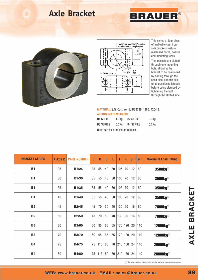
8989WEB: www.brauer.co.uk EMAIL: [email protected]: www.brauer.co.uk EMAIL: [email protected]
AX
LE
BR
AC
KE
TA
XL
E B
RA
CK
ET
®Axle Bracket
This series of four sizesof malleable cast ironaxle brackets featuremachined bores, bossesand mounting faces.
The brackets are slottedthrough one mountinghole, allowing thebracket to be positionedby bolting through thesolid side, and the axleto be positioned laterallybefore being clamped bytightening the boltthrough the slotted side.
MATERIAL: S.G. Cast Iron to BS2789: 1985: 420/12.
APPROXIMATE WEIGHTS:
B1 SERIES 1.3Kg B2 SERIES 2.3Kg
B3 SERIES 5.5Kg B4 SERIES 10.2Kg
Bolts can be supplied on request.
(1) The ‘maximum load rating’ applies with the bracket in compression as shown.
BRACKET SERIES A Axle Ø PART NUMBER B C D E F G Ø H Ø I Maximum Load Rating
B1 25 B1/25 35 55 40 30 105 70 12 60 3500kg(1)
3500kg(1)
3500kg(1)
3500kg(1)
7000kg(1)
7000kg(1)
12000kg(1)
12000kg(1)
20000kg(1)
20000kg(1)
35 55 40 30 105 70 12 60
35 55 40 30 105 70 12 60
35 55 40 30 105 70 12 60
45 70 50 40 130 90 16 80
45 70 50 40 130 90 16 80
60 95 65 55 170 120 20 110
60 95 65 55 170 120 20 110
75 115 80 70 210 150 24 140
75 115 80 70 210 150 24 140
B1/30
B1/35
B1/40
B2/45
B2/50
B3/60
B3/70
B4/75
B4/80
30
35
40
45
50
60
70
75
80
B1
B1
B1
B2
B2
B3
B3
B4
B4

9090 CALL US AT: 00 44 (0)1908 374022 OR FAX US AT: 00 44 (0)1908 641628CALL US AT: 00 44 (0)1908 374022 OR FAX US AT: 00 44 (0)1908 641628
‘A’
SE
RIE
S A
XL
E A
SS
EM
BL
IES
‘A’
SE
RIE
S A
XL
E A
SS
EM
BL
IES
® ‘A’ Series Axle Assemblies®
(2) Axle brackets - see tabulation block for model number and page 30 for full dimensions
These axle assemblies are formounting pairs of wheels fittedwith ball or roller bearings, thelock nuts and washers, or selflocking nuts providingadjustment for opposed taperroller bearings.
Axle diameter ‘A’ and dimension‘D’ should be selected to matchthe bearing bore and hub widthof the wheels to be fitted.
The slotted axle brackets allowlateral positioning of the axle andwheels for alignment oninstallation – see “Axle Brackets”on page 89.
The assembly is suppliedcomplete with axle brackets,bearing retaining/adjustmentnuts, and locking washers.
AXLE MATERIAL:Steel to BS970: Part 1:
1983:606M36 or 605M36.
**** Denotes dimension between bearing abutment shoulders in mm to be specified by the customer.
* The ‘Maximum Load Rating’ applies per wheel: i) to gradually applied loads. For shock loads multiply by a ‘shock loading factor’ of 0.65. ii) to radial loads only. Where axial loads are to be applied in conjunction with radial loads, refer to HMC-Brauer for allowable loads.iii) with axle brackets positioned within ‘dimension E’.
A Axle Ø PART NUMBER Max load
rating kg* Ø B CD
maxminE F G H J Ø K AXLE BRACKET
25 A25/**** 1500 30 62 40 52 75 35 105 70 40 12 B1/3030 A30/**** 2500 35 75 50 65 75 35 105 70 40 12 B1/3535 A35/**** 3000 40 97 60 85 100 35 105 70 40 12 B1/4040 A40/**** 4000 50 113 85 100 100 45 130 90 50 16 B2/5050
60
75
A50/****A60/****A75/****
6300
8500
12000
60
70
85
128
130
150
85
85
85
110
110
110
120
120
150
60
60
75
170
170
210
120
120
150
65
65
80
20
20
24
B3/60B3/70B4/85
(2) Axle brackets - see tabulation block for modelnumber and page 90 for full dimensions.

WEB: www.brauer.co.uk EMAIL: [email protected]: www.brauer.co.uk EMAIL: [email protected]
‘BA
’ S
ER
IES
AX
LE
AS
SE
MB
LIE
S‘B
A’
SE
RIE
S A
XL
E A
SS
EM
BL
IES
9191
®Applications and Examples‘BA’ Series Axle Assemblies
9191
(2) Axle brackets - see tabulationblock for model number and page 30for full dimensions.
The ‘BA’ series axle assemblies are formounting single wheels fitted with ball orroller bearings, the lock nut, lock washer,or self locking nuts and sleeve providingadjustment for opposed taper rollerbearings.
Axle diameter ‘A’ and dimension ‘D’ shouldbe selected to match the bearing bore andhub width of the wheels to be fitted.
The slotted axle brackets, in conjunctionwith the extended major axle diameter andsleeve (dimension ‘C’) allow a widetolerance in the positioning of the brackets,and also allows the wheel to be positionedlaterally between the brackets –see “Axle Brackets” on page 89.
The assembly is supplied complete withaxle brackets, bearing retaining/adjustmentnut and locking washer.
AXLE MATERIAL:Steel to BS970: Part 1: 1983: 606M36or 605M36.
A Axle Ø PART NUMBER Max load
rating kg* B CD
maxminE Ø F G H J K Ø L AXLE
BRACKETWeight
kg30 BA30 3300 225 65 51 80 25 35 35 105 70 40 12 B1/35 4.0
35 BA35 7000 225 65 51 80 25 40 35 105 70 40 12 B1/40 4.7
40 BA40 9000 265 80 70 90 30 50 45 130 90 50 16 B2/50 8.9
50 BA50 14000 340 105 80 110 40 60 60 170 120 65 20 B3/60 19.0
60 BA60 24000 340 105 80 110 40 70 60 170 120 65 20 B3/70 21.3
75 BA75 40000 390 120 80 125 40 85 75 210 150 80 24 B4/85 38.1
* The ‘Maximum Load Rating’ applies: i) to gradually applied loads. For shock loads multiply by a ‘shock loading factor’ of 0.65. ii) to radial loads only. Where axial loads are to be applied in conjunction with radial loads, refer to HMC-Brauer for allowable loads.iii) with axle brackets positioned within ‘dimension E’.
(2) Axle brackets - see tabulation blockfor model number and page 90 forfull dimensions.
®

9292 CALL US AT: 00 44 (0)1908 374022 OR FAX US AT: 00 44 (0)1908 641628CALL US AT: 00 44 (0)1908 374022 OR FAX US AT: 00 44 (0)1908 641628
‘CA
’ S
ER
IES
AX
LE
AS
SE
MB
LIE
S‘C
A’
SE
RIE
S A
XL
E A
SS
EM
BL
IES
® ‘CA’ Series Axle Assemblies
This range of cantilevered stub axles isdesigned to mount single wheels with ballor roller bearings, the lock nut and lockwasher, or self locking nuts providingadjustment for opposed taper rollerbearings.
Axle diameter ‘A’ and dimension ‘D’ shouldbe selected to match the bearing bore andhub width of the wheel to be fitted.
The assembly is supplied complete withbearing retaining/adjustment nut andlocking washer, and a pair of half nuts formounting.
AXLE MATERIAL:Steel to BS970: Part 1: 1983: 606M36 or605M36.
A Axle Ø PART NUMBER Max load
rating kg* B CD
maxminE Thread F Hex G
A/FRecommended minimummounting plate thickness
Weightkg
20 CA20 350 119 50 35 45 15 M27 x 2.0 32 12 0.725 CA25 600 137 60 40 52 15 M30 x 2.0 36 16 1.030 CA30 825 170 75 50 65 20 M36 x 3.0 46 18 1.735 CA35 1100 207 90 60 85 20 M42 x 3.0 50 22 2.5
* The ‘Maximum Load Rating’ applies: i) to gradually applied loads. For shock loads multiply by a ‘shock loading factor’ of 0.65. ii) to radial loads only. Where axial loads are to be applied in conjunction with radial loads, refer to HMC-Brauer for allowable loads.

Non-catalogue items use the same descriptive part numbering system prefixed by the word specified, abbreviated as “spec”.
Castor Type (Series)
Top Plate S = Swivel F = Fixed
Wheel Type (Series)
Wheel Diameter (mm)
Tread Width (mm)
Wheel Bearing Type see opposite
Optional Features see opposite
P S / H 300 / 50 TB / D BEARING TYPESBJ = Ball Journal TB = Taper Roller CRB = Cylindrical Roller PB = Plain Bore SL = Self Lubricating Bush
OPTIONAL FEATURESD = Directional Lock W = Wheel Lock T = Thread Guard B = Footbrake F = Swivel & Wheel Lock X = Wheel Brake S = Head Seal
PART NUMBERING Castors have descriptive part numbers as shown by the following example:
WEB: www.brauer.co.uk EMAIL: [email protected]: www.brauer.co.uk EMAIL: [email protected]
IND
US
TR
IAL
CA
ST
OR
SIN
DU
ST
RIA
L C
AS
TO
RS
9393
®Applications and ExamplesCASTORS SECTION
9393
®

9494 CALL US AT: 00 44 (0)1908 374022 OR FAX US AT: 00 44 (0)1908 641628CALL US AT: 00 44 (0)1908 374022 OR FAX US AT: 00 44 (0)1908 641628
IND
US
TR
IAL
CA
ST
OR
SIN
DU
ST
RIA
L C
AS
TO
RS
® Industrial CastorsTypical Examples of What We Can Offer

9595WEB: www.brauer.co.uk EMAIL: [email protected]: www.brauer.co.uk EMAIL: [email protected]
PN
EU
MA
TIC
TY
RE
D S
ING
LE
WH
EE
LP
NE
UM
AT
IC T
YR
ED
SIN
GL
E W
HE
EL
®Pneumatic Tyred CastorSingle Wheel
ApproxWeight
kg
30
ApproxWeight
kg
35
A B C D Swivel Fixed
535
Wheel Diameter
612
Overall Height
373
Swivel Radius
165
Tread Width
2100
Max Load Rating
Ball Journal
WheelBearing
Type
WGS/PN535/165BJ
PART NUMBER
WGF/PN535/165BJ
PART NUMBER
26
612
Ø535
100
140
105Ø
15
142
175
165
264
R373
WHEEL FACE BRAKE OPTION- SUFFIX ‘WFB’
● High speed applications (up to 10Kph)
● Multi-terrain operation capability
● Option for bespoke applications
● Incorporates reliability of WG swivel mechanism
● Brauer build quality assured
● Often adapted for towing applications
This new product further enhances the range of castors offered by Brauer designed tomeet applications which have high load and speed requirements, such as freight handlingand cargo dollies. The swivel and horn plates utilise our tried and tested WG castor rangeto give a reliable product with durability and strength.
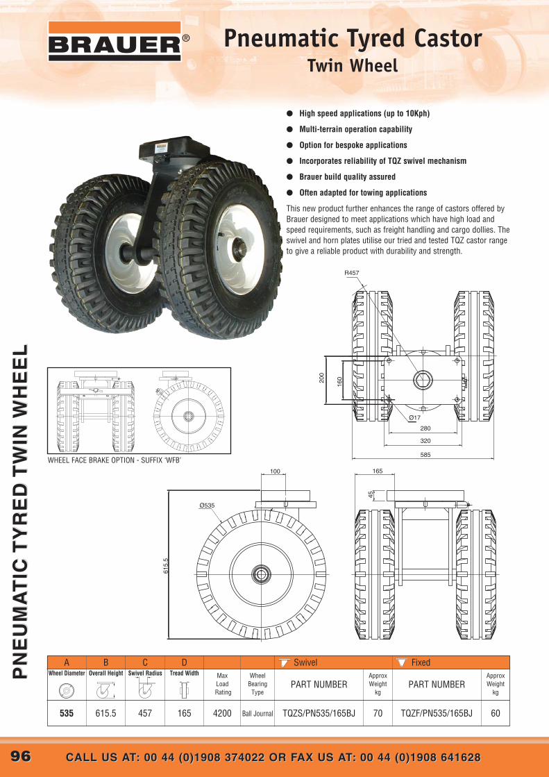
9696 CALL US AT: 00 44 (0)1908 374022 OR FAX US AT: 00 44 (0)1908 641628CALL US AT: 00 44 (0)1908 374022 OR FAX US AT: 00 44 (0)1908 641628
PN
EU
MA
TIC
TY
RE
D T
WIN
WH
EE
LP
NE
UM
AT
IC T
YR
ED
TW
IN W
HE
EL
® Pneumatic Tyred CastorTwin Wheel
● High speed applications (up to 10Kph)
● Multi-terrain operation capability
● Option for bespoke applications
● Incorporates reliability of TQZ swivel mechanism
● Brauer build quality assured
● Often adapted for towing applications
This new product further enhances the range of castors offered byBrauer designed to meet applications which have high load andspeed requirements, such as freight handling and cargo dollies. Theswivel and horn plates utilise our tried and tested TQZ castor rangeto give a reliable product with durability and strength.
ApproxWeight
kg
60
ApproxWeight
kg
70
A B C D Swivel Fixed
535
Wheel Diameter
615.5
Overall Height
457
Swivel Radius
165
Tread Width
4200
Max Load Rating
Ball Journal
WheelBearing
Type
TQZS/PN535/165BJ
PART NUMBER
TQZF/PN535/165BJ
PART NUMBER
165100
45
Ø535
615.
5
280
320
16020
0
585
Ø17
R457
WHEEL FACE BRAKE OPTION - SUFFIX ‘WFB’

9797WEB: www.brauer.co.uk EMAIL: [email protected]: www.brauer.co.uk EMAIL: [email protected]
PIV
OT
ING
CA
ST
OR
SP
IVO
TIN
G C
AS
TO
RS
®Pivoting CastorsLoad rating exceeding 200 Tonne
Pivoting Castors generally consist of a pair of wheels rotating about a central axis.
A pair of wheels on a castor enable a lower overall height to be achieved compared to a single wheel castor of identical loadcapacity. The pivoting design ensures that the load is equally distributed over both wheels should the running surface beslightly uneven. This prevents overload on the wheels, a common problem with conventional twin wheel castor assemblies.
For high loads, the overall height can be further reduced by a multi - pivoting arrangement.
These castors are designed to suit individual applications and can be supplied with stress analysis graphs using finiteelement analysis for the castor frame.
Brauer has many years experience in the design andmanufacture of such assemblies with load ratings up toand exceeding 200 tonne

9898 CALL US AT: 00 44 (0)1908 374022 OR FAX US AT: 00 44 (0)1908 641628CALL US AT: 00 44 (0)1908 374022 OR FAX US AT: 00 44 (0)1908 641628
HE
AV
Y D
UT
Y C
AS
TO
RS
HE
AV
Y D
UT
Y C
AS
TO
RS
® Heavy Duty Castors
The UHQZ, HQZ, TQZ, QZ, WG,TWG, GG and LG are made from precision machinedcomponents to ensure a long and trouble-free life, even underthe most severe operating conditions.
DESIGN FEATURES

9999WEB: www.brauer.co.uk EMAIL: [email protected]: www.brauer.co.uk EMAIL: [email protected]
UH
QZ
SE
RIE
S C
AS
TO
RS
UH
QZ
SE
RIE
S C
AS
TO
RS
®UHQZ Series Swivel load rating 12000kg
FOR TECHNICAL INFORMATION COVERING LOAD FACTORS, ETC., SEE ‘DESIGN DATA’ INDEX ON PAGE 20
ApproxWeight
kg
130
ApproxWeight
kg
178
192240
WITH A VARIETY OF WHEEL OPTIONS (SEE TABLE BELOW)
A B C D Swivel Fixed
460
500
WheelDiameter
595
635
OverallHeight
75
100
TreadWidth
240
240
Dim.between
HornPlates
6400
9600
Max Load Rating
Tapered
Roller
Tapered
Roller
WheelBearing
Type
UHQZS/H460/75TB
UHQZS/PH500/100TB
PART NUMBER
UHQZF/H460/75TB
UHQZF/PH500/100TB
PART NUMBER
E
150
150
WheelCentreOff-set
F
390
412
SwivelRadius
SWIVELNote: Steel Wheel option shown
240
400
300
3404 X HOLES Ø17
VIEW ON ‘Z’
Top plates have fixing holes to suit 16mm diameter bolts
Swivel top plate thickness 50mm (G)
Fixed top plate thickness 25mm (H)
B
H
C C
D
'Z'
G
E
A
A
E
C
C F
Directional locks are standard on UHQZS series castors.
132180350 465 110 130 12000Tapered
RollerUHQZS/SFT350/110TB UHQZF/SFT350/110TB150 330
STEEL WHEEL
POLYURETHANE TYRED ‘PRESS-ON BAND’ WHEEL
DIRECT BOND POLYURETHANE TYRED WHEEL
Note: Steel wheel is a single wheel
NOTE: Also available with other wheel types.

100100 CALL US AT: 00 44 (0)1908 374022 OR FAX US AT: 00 44 (0)1908 641628CALL US AT: 00 44 (0)1908 374022 OR FAX US AT: 00 44 (0)1908 641628
HQ
Z S
ER
IES
CA
ST
OR
SH
QZ
SE
RIE
S C
AS
TO
RS
® HQZ Series Swivel load rating 7300kg
5795385 90 110 7300Tapered
RollerHQZS/SFT200/90TB HQZF/SFT200/90TB100 205
FOR TECHNICAL INFORMATION COVERING LOAD FACTORS, ETC., SEE ‘DESIGN DATA’ INDEX ON PAGE 20
ApproxWeight
kg
71
ApproxWeight
kg
109
127168
A B C D Swivel Fixed
300
380
WheelDiameter
435
515
OverallHeight
100
100
TreadWidth
240
240
Dim.between
HornPlates
6200
7200
Max Load Rating
Tapered
Roller
Tapered
Roller
WheelBearing
Type
HQZS/H300/100TB
HQZS/PH380/100TB
PART NUMBER
HQZF/H300/100TB
HQZF/PH380/100TB
PART NUMBER
E
100
125
WheelCentreOff-set
F
270
331
SwivelRadius
190
400
230
3604 X HOLES Ø17
VIEW ON ‘Z’
Top plates have fixing holes to suit 16mm diameter bolts
Swivel top plate thickness 50mm (G)
Fixed top plate thickness 20mm (H)
'Z'
B
H
C C
D
G
E
A
A
E
C
C F
200
Directional locks are standard on HQZS series castors.
WITH A VARIETY OF WHEEL OPTIONS (SEE TABLE BELOW)
TWIN WHEEL FIXEDNote: Direct Bond Polyurethane Wheel shown
STEEL WHEEL
POLYURETHANE TYRED ‘PRESS-ON BAND’ WHEEL
DIRECT BOND POLYURETHANE TYRED WHEEL
Note: Steel wheel is a single wheel
NOTE: Also available with other wheel types.

101101WEB: www.brauer.co.uk EMAIL: [email protected]: www.brauer.co.uk EMAIL: [email protected]
TQ
Z S
ER
IES
CA
ST
OR
ST
QZ
SE
RIE
S C
AS
TO
RS
®TQZ Series Swivel load rating 5100kg
WITH A VARIETY OF WHEEL OPTIONS (SEE TABLE BELOW)
FOR TECHNICAL INFORMATION COVERING LOAD FACTORS, ETC., SEE ‘DESIGN DATA’ INDEX ON PAGE 20
ApproxWeight
kg
46
ApproxWeight
kg
67
6283
A B C D Swivel Fixed
250
250
WheelDiameter
355
355
OverallHeight
70
75
TreadWidth
190
190
Dim.between
HornPlates
4000
4000
Max Load Rating
Tapered
Roller
Tapered
Roller
WheelBearing
Type
TQZS/H250/70TB
TQZS/PH250/75TB
PART NUMBER
TQZF/H250/70TB
TQZF/PH250/75TB
PART NUMBER
E
85
85
WheelCentreOff-set
F
222
5576300 405 75 190 4600Tapered
RollerTQZS/H300/75TB TQZF/H300/75TB100 262
224
79100300 405 75 190 5000Tapered
RollerTQZS/PH300/75TB TQZF/PH300/75TB100 260
5566200 330 90 110 5100Tapered
RollerTQZS/SFT200/90TB TQZF/SFT200/90TB85 195
SwivelRadius
160
320
200
2804 X HOLES Ø17
VIEW ON ‘Z’
Top plates have fixing holes to suit 16mm diameter bolts
Swivel top plate thickness 45mm (G)
Fixed top plate thickness 20mm (H)
'Z'
B
H
C C
D
E
A
G
A
E
C
C F
Directional locks are standard on TQZS series castors.
TWIN WHEEL SWIVELNote: Direct Bond Polyurethane Wheel shown
DIRECT BOND POLYURETHANE TYRED TWIN WHEEL
POLYURETHANE TYRED ‘PRESS-ON BAND’ TWIN WHEEL
STEEL WHEEL
NOTE: Also available with other wheel types.

102102 CALL US AT: 00 44 (0)1908 374022 OR FAX US AT: 00 44 (0)1908 641628CALL US AT: 00 44 (0)1908 374022 OR FAX US AT: 00 44 (0)1908 641628
QZ
SE
RIE
S C
AS
TO
RS
QZ
SE
RIE
S C
AS
TO
RS
® QZ Series Swivel load rating 4200kg
FOR TECHNICAL INFORMATION COVERING LOAD FACTORS, ETC., SEE ‘DESIGN DATA’ INDEX ON PAGE 20
ApproxWeight
kg
43
ApproxWeight
kg
43
7070
A B C D Swivel Fixed
12" 300
15" 380
Wheel Diameter
375
450
Overall Height
250
315
Swivel Radius
100
100
Tread Width
3100
3600
Max Load Rating
Taper Roller
Taper Roller
WheelBearing
Type
QZS/H300/100TB
QZS/PH380/100TB
PART NUMBER
QZF/H300/100TB
QZF/PH380/100TB
47478" 200 325 200 90 4200 Taper Roller QZS/SFT200/90TB QZF/SFT200/90TB
PART NUMBER
POLYURETHANE TYRED WHEEL
POLYURETHANE ‘PRESS-ON BAND’ TYRED WHEEL
STEEL WHEEL
WITH A VARIETY OF WHEEL OPTIONS (SEE TABLE BELOW)
Wheel locks and directional locks are available on QZ series swivel castors. To order, add the appropriate suffix(es) to the castor part number: W = wheel lock D = directional lock.
SWIVELNote: Press-on band polyurethane wheel shown
Top plates have fixing holes to suit 16mm diameter bolts
(E) Swivel top plate thickness 32mm
(H) Fixed top plate thickness 16mm
D
E or H
NOTE: Also available with other wheel types.

103103WEB: www.brauer.co.uk EMAIL: [email protected]: www.brauer.co.uk EMAIL: [email protected]
QZ
SE
RIE
S C
AS
TO
RS
QZ
SE
RIE
S C
AS
TO
RS
®TWG Series Swivel load rating 3000kg
TWIN WHEEL SWIVEL
WITH A VARIETY OF WHEEL OPTIONS (SEE TABLE BELOW)
Directional locks are standard on TWG series castors.
105
175
142
1404 X HOLES Ø15
'Z'
B
12
C C
D
E
A
26
A
E
C
C F
FOR TECHNICAL INFORMATION COVERING LOAD FACTORS, ETC., SEE ‘DESIGN DATA’ INDEX ON PAGE 20
ApproxWeight
kg
15
ApproxWeight
kg
15
A B C D Swivel Fixed
150
WheelDiameter
220
OverallHeight
35
TreadWidth
90
Dim.between
HornPlates
1200
Max Load Rating
Tapered
Roller
WheelBearing
Type
TWGS/H150/35TB
PART NUMBER
TWGF/H150/35TB
PART NUMBER
E
50
WheelCentreOff-set
F
131
SwivelRadius
POLYURETHANE TYRED WHEEL
NOTE: Also available with other wheel types.
Top plates have fixing holes to suit 14mm diameter bolts
(E) Swivel top plate thickness 26mm
(H) Fixed top plate thickness 12mm

104104 CALL US AT: 00 44 (0)1908 374022 OR FAX US AT: 00 44 (0)1908 641628CALL US AT: 00 44 (0)1908 374022 OR FAX US AT: 00 44 (0)1908 641628
WG
SE
RIE
S C
AS
TO
RS
WG
SE
RIE
S C
AS
TO
RS
® WG Series Swivel load rating 3000kg
WITH A VARIETY OF WHEEL OPTIONS (SEE TABLE BELOW)
ApproxWeight
kg
ApproxWeight
kg
A B C D Swivel FixedWheel Diameter Overall Height Swivel Radius Tread Width Max
Load Rating
WheelBearing
TypePART NUMBER
13136" 150 220 125 50 900 Taper Roller WGS/H150/50TB WGF/H150/50TB
24.424.48" 200 265 160 75 1750 Taper Roller WGS/H200/75TB WGF/H200/75TB
222210" 250 310 200 70 2000 Taper Roller WGS/H250/70TB WGF/H250/70TB
262612" 300 375 250 75 2300 Taper Roller WGS/H300/75TB WGF/H300/75TB
303010" 250 310 200 75 2000 Taper Roller WGS/PH250/75TB WGF/PH250/75TB
383812" 300 375 250 75 2500 Taper Roller WGS/PH300/75TB WGF/PH300/75TB
22226" 150 220 125 40 3000 Taper Roller WGS/SFT150/40TB WGF/SFT150/40TB
PART NUMBER
POLYURETHANE TYRED WHEEL
Top plates have fixing holes to suit 14mm diameter bolts
(E) Swivel top plate thickness 26mm
(H) Fixed top plate thickness 12mm
Wheel locks and directional locks are available on WG series swivel castors. To order, add the appropriate suffix(es) to the castor part number: W = wheel lock D = directional lock.
SWIVELNote: Direct Bond Polyurethane Wheel shown
POLYURETHANE ‘PRESS-ON-BAND’ TYRED WHEEL
STEEL WHEEL
D
E or H
FOR TECHNICAL INFORMATION COVERING LOAD FACTORS, ETC., SEE ‘DESIGN DATA’ INDEX ON PAGE 20
NOTE: Also available with other wheel types.

105105WEB: www.brauer.co.uk EMAIL: [email protected]: www.brauer.co.uk EMAIL: [email protected]
GG
SE
RIE
S C
AS
TO
RS
GG
SE
RIE
S C
AS
TO
RS
®GG Series Swivel load rating 1500kg
WITH A VARIETY OF WHEEL OPTIONS (SEE TABLE BELOW)
ApproxWeight
kg
ApproxWeight
kg
A B C D Swivel FixedWheel Diameter Overall Height Swivel Radius Tread Width Max
Load Rating
WheelBearing
TypePART NUMBER
884" 100 165 90 40 450 Ball Journal GGS/H100/40BJ GGF/H100/40BJ
996" 150 216 125 50 900 Ball Journal GGS/H150/50BJ GGF/H150/50BJ
11118" 200 267 160 40 900 Ball Journal GGS/H200/40BJ GGF/H200/40BJ
161610" 250 318 195 45 1300 Ball Journal GGS/H250/45BJ GGF/H250/45BJ
PART NUMBER
FOR TECHNICAL INFORMATION COVERING LOAD FACTORS, ETC., SEE ‘DESIGN DATA’ INDEX ON PAGE 20
POLYURETHANE TYRED WHEEL
Top plates have fixing holes to suit 12mm diameter bolts
(E) Swivel top plate thickness 24mm
(H) Fixed top plate thickness 12mm
Wheel locks and directional locks are available on WG series swivel castors. To order, add the appropriate suffix(es) to the castor part number: W = wheel lock D = directional lock.
NOTE: Also available with other wheel types.
SWIVELNote: Direct Bond Polyurethane Wheel shown

106106 CALL US AT: 00 44 (0)1908 374022 OR FAX US AT: 00 44 (0)1908 641628CALL US AT: 00 44 (0)1908 374022 OR FAX US AT: 00 44 (0)1908 641628
ME
DIU
M-H
EA
VY
DU
TY
CA
ST
OR
SM
ED
IUM
-HE
AV
Y D
UT
Y C
AS
TO
RS
® Medium-Light CastorsLG Series
SwivelRadius
FOR TECHNICAL INFORMATION COVERING LOAD FACTORS, ETC., SEE ‘DESIGN DATA’ INDEX ON PAGE 20
ApproxWeight
kg
8
ApproxWeight
kg
8
A B C D Swivel Fixed
150
WheelDiameter
200
OverallHeight
122 55
Dim.between
HornPlates
600
Max Load Rating
kg
BallJournal
WheelBearing
Type
LGS/H150/35BJ
PART NUMBER
LGF/H150/35BJ
PART NUMBER
E
35
77125 187.5 110 55 600 BallJournal LGS/H125/45BJ LGF/H125/45BJ45
77125 187.5 110 55 400 BallJournal LGS/H125/30BJ LGF/H125/30BJ30
POLYURETHANE TYRED WHEEL
TreadWidth
Top plates have fixing holes to suit 10mm diameter bolts
(G) Swivel top plate thickness 6mm
(H) Fixed top plate thickness 6mm
Wheel locks and directional locks are available on WG series swivel castors. To order, add the appropriate suffix(es) to the castor part number: W = wheel lock D = directional lock.
FIXED
NOTE: Also available with other wheel types.
SWIVEL

107107WEB: www.brauer.co.uk EMAIL: [email protected]: www.brauer.co.uk EMAIL: [email protected]
25
00
KG
JA
CK
ING
UN
IT2
50
0K
G J
AC
KIN
G U
NIT
®2500kg Jacking UnitJU2500
Brauer have developed a Jacking Unit, which is now available forgeneral purchase. The Jacking unit is adaptable to manyenvironments and applications due to our in house design team andmanufacturing capability.
Many options are available due to the integration of our WG SeriesCastor into the design, giving unsurpassed flexibility to the marketplace.
Availability and delivery are enhanced because we are a leading UKmanufacturer and control all aspects of the Jacking Unit.
Load rating up to 2500kg per unit.
Bespoke design which is now incorporated into our full range ofwheels and castors
Robust design.
Designed to suit our WG castor range.
Wheel options from 150mm to 300mm diameter.
Swivel and fixed castor options.
Flat foot option for non castor applications.
Approximate weight 35Kg.
NOTE: Also available with other wheel types.

®
108108 CALL US AT: 00 44 (0)1908 374022 OR FAX US AT: 00 44 (0)1908 641628CALL US AT: 00 44 (0)1908 374022 OR FAX US AT: 00 44 (0)1908 641628
10
00
KG
JA
CK
ING
UN
IT1
00
0K
G J
AC
KIN
G U
NIT
1000kg Jacking UnitJU1000
108108
Brauer have developed a range of jacking units expandingfurther our comprehensive range of heavy duty castorsand wheels. The jacking units are highly adaptable acrossa broad range of environments and applications. Manyoptions are available giving this new product unsurpassedflexibility for the worlwide market place. Availability anddelivery is enhanced due to products being totallymanufactured within the wheels and castors divisionbased in the UK. Robust design. Load rating up to1000kg per unit. Integral swivel mechanism incorporatedinto jacking castor. Designed to suit our GG fixed castor.Wheel options from 100mm to 250mm diameter. Wheeloptions include steel, polyurethane and nylon. Jackingunits now form part of Brauer comprehensive range ofwheels and castors.Approximate weight: 25Kg
B
D
A
12
Ø12.2
76
108
134
162
C
ApproxWeight
kg
A B C DWheel Diameter Overall Height
OverallLength
WheelWidth
Max Load Rating
WheelBearing
TypePART NUMBER
8100 133 171 40 450 Ball Journal JGG/H100/40BJ
9150 184 206 50 900 Ball Journal JGG/H150/50BJ
11200 235 241 40 900 Ball Journal JGG/H200/40BJ
16250 286 276 45 1300 Ball Journal JGG/H250/45BJ
FOR TECHNICAL INFORMATION COVERING LOAD FACTORS, ETC., SEE ‘DESIGN DATA’ INDEX ON PAGE 20
NOTE: Also available with otherwheel types.

®
109109WEB: www.brauer.co.uk EMAIL: [email protected]: www.brauer.co.uk EMAIL: [email protected]
H S
ER
IES
CA
ST
OR
SH
SE
RIE
S C
AS
TO
RS
H Series Swivel load rating 1500kg
POLYURETHANE TYRED WHEEL WITH C.I. CENTRE
FOR TECHNICAL INFORMATION COVERING LOAD FACTORS, ETC., SEE ‘DESIGN DATA’ INDEX ON PAGE 12
ApproxWeight
kg
3
ApproxWeight
kg
3.9
3.13.6
44.5
3.74.7
4.65.6
5.86.7
8.99.8
1212.9
NOTE 1) 100mm diameter wheel fitted with pre-lubricated, double shielded bearings2) Options (F) & (X) – swivel radius of brake pedal 178mm
DIRECTIONAL LOCK (D)Swivel castors onlyA four-stationplunger lockconverting swivelcastors into fixed forstraight line travel
Add suffix D to partnumber
WHEEL LOCK (W)Swivel castors only, notavailable for100mm dia. wheelA simple handoperated parkinglock
Add suffix Wto part number
SWIVEL AND WHEEL LOCK (F)WHEEL BRAKE (X)Swivel castors only125-300mm onlyThe foot pedal clamps a springacross the wheel & swivel,locking them both (F), or thewheel only is braked (X)Add suffix F or X to part number
OPTIONS AVAILABLE
A B C D Swivel Fixed
4" 100
Wheel Diameter
152
Overall Height
102
Swivel Radius
40
Tread Width
500
Max Load Rating
Ball Journal
WheelBearing
Type
HS/H100/40BJ
PART NUMBER
HF/H100/40BJ
5" 125 177 1183045
500600
Ball Journal
Ball Journal
HS/H125/30BJHS/H125/45BJ
HF/H125/30BJHF/H125/45BJ
6" 150 202 1343550
700900
Ball Journal
Ball Journal
HS/H150/35BJHS/H150/50BJ
HF/H150/35BJHF/H150/50BJ
8" 200 252 166 40 1000 Ball Journal HS/H200/40BJ HF/H200/40BJ
10" 250 303 207 45 1200 Ball Journal HS/H250/45BJ HF/H250/45BJ
12" 300 353 245 50 1500 Ball Journal HS/H300/50BJ HF/H300/50BJ
PART NUMBER
SWIVEL FIXED
D
BA
C
When fitting at 120 x 60mm holecentres use 12mm diameter bolts
When fitting at 105 x 80/75mm holecentres use 10mm diameter bolts
Swivel top plate thickness 7mm
Fixed top plate thickness 6.5mm
NOTE: Also available with other wheel types.

110110 CALL US AT: 00 44 (0)1908 374022 OR FAX US AT: 00 44 (0)1908 641628CALL US AT: 00 44 (0)1908 374022 OR FAX US AT: 00 44 (0)1908 641628
F S
ER
IES
UK
STA
ND
AR
DF
SE
RIE
S U
K S
TAN
DA
RD
®
SWIVEL (NOTE: foot brake not fitted as standard) FIXED
F Series Swivel load rating 360kg†
FOR TECHNICAL INFORMATION COVERING LOAD FACTORS, ETC., SEE ‘DESIGN DATA’ INDEX ON PAGE 14
ApproxWeight
kg
ApproxWeight
kg
A B C D Swivel FixedWheel Diameter Overall Height Swivel Radius Tread Width Max
Load Rating
WheelBearing
TypePART NUMBER
3" 75 94 60 35 120 Ball Journal FS/H75/35BJ FF/H75/35BJ2.9 1.93.0 2.0
4" 100 125 75 40 250 Ball Journal FS/H100/40BJ FF/H100/40BJ1.8 0.8
5" 125 154 98 30 295 Ball Journal FS/H125/30BJ FF/H125/30BJ3.6 2.66" 150 182 117 35 360 Ball Journal FS/H150/35BJ FF/H150/35BJ
PART NUMBER
CAST IRON CENTRED WHEEL WITH POLYURETHANE TYRE
NOTE Part Numbers FS/H75/35BJ and FS/H100/40BJ are fitted with pre-lubricated, double-shielded bearings
BA
D
C
Wheel Dia. Plate Size Hole Centres Fixing BoltDia.
80/86 x 60100/105 x 76/80
120/140 x 95/105120/140 x 95/105
105 x 80128 x 102162 x 132162 x 132
75100125150
8101010
SWIVEL CASTORS TOP PLATE DIMENSIONSWheel Dia. Plate Size Hole Centres Fixing Bolt
Dia.
80/83 x 3597/100 x 4897/100 x 48
130 x 67
101 x 63120 x 80120 x 80171 x 108
75100125150
8101010
FIXED CASTORS TOP PLATE DIMENSIONS
†The swivel load rating is dependent on the wheel sizeUK STANDARD
FOOTBRAKE (B)✱
75, 100mm swivelcastors onlyThe foot operated leverlocks wheel
Add suffix B to partnumber
OPTIONS AVAILABLE NOTE: Also available with other wheel types.

111111WEB: www.brauer.co.uk EMAIL: [email protected]: www.brauer.co.uk EMAIL: [email protected]
FL
OO
R L
OC
KS
FL
OO
R L
OC
KS
®Floor Locks
†The swivel load rating is dependent on the wheel sizeUK STANDARD
A POSITIVE MEANS OF SECURING MOBILE EQUIPMENT
13792
9467 FL-0101
FL-0206FL-0207
85100 120
120
85100
11492
10166FL-0209FL-0210
B1B 2
E
CD
A
Floor lock top plateshave fixing holes to suit
10mm diameter bolts
A
4" 100
6" 150
B1
143150143210197
B2
119125128170171
Retracted Height
C
7214092
14592
D
205
528
52
E
10380808080
FL-0101FL-0206FL-0209FL-0207FL-0210
MODEL NUMBER
Designed to steady the equipment to which they are fitted and stop horizontal movement, floor locks are never intended to act as ajack. Any attempt to vary the fitting height from the catalogue specification will give failure and/or damage. There is some built-inresilience in the foot pad, which will allow some variations in floor level. Nonetheless it is essential that the floor lock is fitted asclosely as possible to one of the swivel castors. Please note that the floor lock can be severely damaged if the linkage is operatedwhilst the truck is moving.
For Castors WithWheel Diameter
Mounting Height

CALL US AT: 00 44 (0)1908 374022 OR FAX US AT: 00 44 (0)1908 641628CALL US AT: 00 44 (0)1908 374022 OR FAX US AT: 00 44 (0)1908 641628112112
® WHATEVER YOUR CLAMPING NEEDSCHOOSE THE MARKET LEADER
POSITIVE LOCKINGCLAMPS
Unique mechanical locking lever forpositive safety locking in clampedand open position. Holding force 250daN to 350 daN.
Hydraulic forces with manualoperation.
HEAVY DUTY CAMCLAMPS
Mounted directly into a threaded orplain hole in a fixture. Can also bemounted in a bracket. Holding force50 daN to 400 daN.
PUSH-PULL CLAMPS
Exceptionally robust construction.Holding forces to 5000 daN.
With holding forces from 70 daN to550 daN. Supplied complete with allhardware.
HEAVY DUTYPUSH-PULL CLAMPS
With holding forces from 300 daN to2400 daN. Supplied complete withrelevant hardware.
HEAVY DUTY VERTICALCLAMPSVERTICAL CLAMPS
With holding forces from 50 daN to700 daN. Supplied complete with allhardware.
HORIZONTAL CLAMPS
PNEUMATIC POWERCLAMPS
Mounting adaption to suit customerrequirement.
Also
avail
able
in
Stainl
ess S
teel
Also
avail
able
in
Stainl
ess S
teel
Also
avail
able
in
Stainl
ess S
teel
AIRMOVER PRODUCTSSTRIP AIRMOVERS
Lengths from 75mmn to 900mmFor “Air Sheet” applications*
COLD AIR GUNMODEL Nos. AG32, CG22
TRIGGER ACTIONBLOW GUN
The new Brauer cold air gun air coolant system.MODEL Nos. CG4, CG4A, CG4ANF, CG4N,
CG4AN, GC4NF*
FIXED GAP AIRMOVER
“AM” series airmovers used for conveyingcooling and extraction
*AVAILABLE IN STAINLESS STEEL
FOR COOLING, CONVEYING & DRYING

®OTHER BRAUER CATALOGUES
WEB: www.brauer.co.uk EMAIL: [email protected]: www.brauer.co.uk EMAIL: [email protected]

TEL: 00 44 (0)1908 374022 FAX: 00 44 (0)1908 641628E-mail: [email protected] Web: www.brauer.co.uk
For further details contact Authorised Dealer stamp
02/0