what about the easy-nlc system (nanoflow liquid we ... · for more information about the easy-nlc...
TRANSCRIPT

For more information about the EASY-nLC 1000 model, please check the following document.
What about the EASY-nLC 1000 system (nanoflow liquid chromatograph) ? We have great news… IonBench has now a new innovative movable bench for this product of Thermo Scientific!
IonBenchTM is supplying pharmaceutical, environmental, clinical and university laboratories.
IonBenchTM products are designed to ease the day to day use of your LC/GC/MS, by providing a significant
number of features that makes your working conditions better:
Quieter environment with an integrated noise reduction enclosure, including cooling. system
based on silent fan technology and with an overheating temperature alarm (audible & visual, on a
battery back-up).
Increased accessibility with a fully movable Mass Spectrometer bench.
Vacuum pumps stored on a specific patented absorbing vibration rack
Better ergonomics and security in labs, by using a bench designed for your application taking into
consideration your specific requirements (Electricity, monitor arm, solvent storage…).
Ion Benches are compatible with all major Mass Spectrometry brands, such as Agilent, AB Sciex, Bruker,
Jeol, Leco, Perkin Elmer, Shimadzu, Thermo Scientific, Waters…

Thermo
EASY-nLC SeriesGetting Started Guide(Software version 3.1)
60053-97229 Revision C January 2013

© 2013 Thermo Fisher Scientific Inc. All rights reserved.
AFC, EASY-nLC, EASY-Spray, EASY-column, IFC, Nanospray Flex, nanoViper, and PepMap are trademarks, and Acclaim, Dionex, LCQ Fleet, LXQ, LTQ, TSQ, and Xcalibur are registered trademarks of Thermo Fisher Scientific Inc.
PEEK is a trademark of Victrex PLC. PEEKsil is a trademark of SGE International Pty Ltd Corp.
The following are registered trademarks in the United States: Advion and RePlay are registered trademarks of Advion Biosystems, Inc. Agilent and Varian are registered trademarks of Agilent Technologies Inc. Bruker is a registered trademark of Bruker Corporation. CMOSens is a registered trademark of Sensirion AG Corp. Duran is a registered trademark of Schott AG. Linux is a registered trademark of Linus Torvald. Micromass and Waters are registered trademarks of Waters Corporation. PhotoMOS is a registered trademark of Panasonic Electric Works, Co., Ltd. Sciex is a registered trademark of Applied Biosystems Life Technologies. SSH is a registered trademark of Tectia Corporation. Teflon is a registered trademark of E.I. du Pont de Nemours and Company. VICI and Valco are registered trademarks of Valco Instruments Co. Inc.
Microsoft and Windows are registered trademarks of the Microsoft Corporation in the United States and other countries.
All other trademarks are the property of Thermo Fisher Scientific and its subsidiaries.
Thermo Fisher Scientific Inc. provides this document to its customers with a product purchase to use in the product operation. This document is copyright protected and any reproduction of the whole or any part of this document is strictly prohibited, except with the written authorization of Thermo Fisher Scientific Inc.
The contents of this document are subject to change without notice. All technical information in this document is for reference purposes only. System configurations and specifications in this document supersede all previous information received by the purchaser.
Thermo Fisher Scientific Inc. makes no representations that this document is complete, accurate or error-free and assumes no responsibility and will not be liable for any errors, omissions, damage or loss that might result from any use of this document, even if the information in the document is followed properly.
This document is not part of any sales contract between Thermo Fisher Scientific Inc. and a purchaser. This document shall in no way govern or modify any Terms and Conditions of Sale, which Terms and Conditions of Sale shall govern all conflicting information between the two documents.
Release history: Revision A, March 2012; Revision B, July 2012, Revision C, January 2013. This revision includes information about software downloads from the EASY-nLC Customer User Zone Web site.
Hardware versions: EASY-nLC II and EASY-nLC 1000 instruments
Software version: Touch-screen software version 3.1
For Research Use Only. Not for use in diagnostic procedures.

Thermo Scientific EASY-nLC Series Getting Started Guide iii
C
Preface . . . . . . . . . . . . . . . . . . . . . . . . . . . . . . . . . . . . . . . . . . . . . . . . . . . . . . . . . . . . . viiRelated Documentation . . . . . . . . . . . . . . . . . . . . . . . . . . . . . . . . . . . . . . . . . . viiDownloading Manuals from the Customer Manuals Web Site . . . . . . . . . . . . .viiiSafety and Special Notices . . . . . . . . . . . . . . . . . . . . . . . . . . . . . . . . . . . . . . . . .ixContacting Us . . . . . . . . . . . . . . . . . . . . . . . . . . . . . . . . . . . . . . . . . . . . . . . . . .xiRegulatory Compliance . . . . . . . . . . . . . . . . . . . . . . . . . . . . . . . . . . . . . . . . . . xiiDeclaration of Conformity for the EASY-nLC II System . . . . . . . . . . . . . . . . .xivDeclaration of Conformity for the EASY-nLC 1000 System. . . . . . . . . . . . . . .xvi
Chapter 1 Introduction . . . . . . . . . . . . . . . . . . . . . . . . . . . . . . . . . . . . . . . . . . . . . . . . . . . . . . . . . . .1Instrument Hardware and Software Components and Connections . . . . . . . . . . 2Autosampler Tray Compartment. . . . . . . . . . . . . . . . . . . . . . . . . . . . . . . . . . . . . 4External Solvent Lines . . . . . . . . . . . . . . . . . . . . . . . . . . . . . . . . . . . . . . . . . . . . . 5Back Panel. . . . . . . . . . . . . . . . . . . . . . . . . . . . . . . . . . . . . . . . . . . . . . . . . . . . . . 6Column Setup Options . . . . . . . . . . . . . . . . . . . . . . . . . . . . . . . . . . . . . . . . . . . . 8
Two-Column Setup . . . . . . . . . . . . . . . . . . . . . . . . . . . . . . . . . . . . . . . . . . . . 8One-Column Setup. . . . . . . . . . . . . . . . . . . . . . . . . . . . . . . . . . . . . . . . . . . . . 9
Solvent System Components . . . . . . . . . . . . . . . . . . . . . . . . . . . . . . . . . . . . . . . 11Syringe Pumps. . . . . . . . . . . . . . . . . . . . . . . . . . . . . . . . . . . . . . . . . . . . . . . . 11Pressure Sensors. . . . . . . . . . . . . . . . . . . . . . . . . . . . . . . . . . . . . . . . . . . . . . . 11Flow Sensors . . . . . . . . . . . . . . . . . . . . . . . . . . . . . . . . . . . . . . . . . . . . . . . . . 12Six-Port Rotary Valves. . . . . . . . . . . . . . . . . . . . . . . . . . . . . . . . . . . . . . . . . . 13Check Valve Assemblies. . . . . . . . . . . . . . . . . . . . . . . . . . . . . . . . . . . . . . . . . 14Mixing Tee . . . . . . . . . . . . . . . . . . . . . . . . . . . . . . . . . . . . . . . . . . . . . . . . . . 14
Predefined Steps for Sample Runs . . . . . . . . . . . . . . . . . . . . . . . . . . . . . . . . . . . 15Overview of a Sample Run . . . . . . . . . . . . . . . . . . . . . . . . . . . . . . . . . . . . . . 15Sequence of Events for Each Step of a Sample Run . . . . . . . . . . . . . . . . . . . . 18
Pump Flow Control . . . . . . . . . . . . . . . . . . . . . . . . . . . . . . . . . . . . . . . . . . . . . 31Automatic Flow Control System . . . . . . . . . . . . . . . . . . . . . . . . . . . . . . . . . . 31Intelligent Flow Control . . . . . . . . . . . . . . . . . . . . . . . . . . . . . . . . . . . . . . . . 32Load Speed Protection. . . . . . . . . . . . . . . . . . . . . . . . . . . . . . . . . . . . . . . . . . 33
Contents

Contents
iv EASY-nLC Series Getting Started Guide Thermo Scientific
Chapter 2 Installing the EASY-nLC Instrument. . . . . . . . . . . . . . . . . . . . . . . . . . . . . . . . . . . . . .35Lifting Instructions . . . . . . . . . . . . . . . . . . . . . . . . . . . . . . . . . . . . . . . . . . . . . . 36Laboratory Requirements . . . . . . . . . . . . . . . . . . . . . . . . . . . . . . . . . . . . . . . . . 37
Benchtop Requirements . . . . . . . . . . . . . . . . . . . . . . . . . . . . . . . . . . . . . . . . 37Internet Access . . . . . . . . . . . . . . . . . . . . . . . . . . . . . . . . . . . . . . . . . . . . . . . 39Power and Fuse Requirements. . . . . . . . . . . . . . . . . . . . . . . . . . . . . . . . . . . . 39Temperature and Humidity Requirements . . . . . . . . . . . . . . . . . . . . . . . . . . 39
Back Panel Connections . . . . . . . . . . . . . . . . . . . . . . . . . . . . . . . . . . . . . . . . . . 40Connecting to Line Power. . . . . . . . . . . . . . . . . . . . . . . . . . . . . . . . . . . . . . . 41Connecting to the Mass Spectrometer through Contact Closure . . . . . . . . . . 42Connecting the Ethernet Communication Cables . . . . . . . . . . . . . . . . . . . . . 43Attaching a Mouse and Keyboard to the USB Connections. . . . . . . . . . . . . . 47Attaching Add-on Devices through the P-Bus and RS-232 . . . . . . . . . . . . . . 47
Chapter 3 Integrated Instrument Control Software . . . . . . . . . . . . . . . . . . . . . . . . . . . . . . . . . .49Turning On the EASY-nLC Instrument . . . . . . . . . . . . . . . . . . . . . . . . . . . . . . 50Using the Touch-Sensitive Screen . . . . . . . . . . . . . . . . . . . . . . . . . . . . . . . . . . . 51
Using the Buttons . . . . . . . . . . . . . . . . . . . . . . . . . . . . . . . . . . . . . . . . . . . . . 52Inputting Alphanumeric Text . . . . . . . . . . . . . . . . . . . . . . . . . . . . . . . . . . . . 52Using Tables and Input Fields . . . . . . . . . . . . . . . . . . . . . . . . . . . . . . . . . . . . 52Interactive Graphical Controls. . . . . . . . . . . . . . . . . . . . . . . . . . . . . . . . . . . . 53
Viewing the System Status. . . . . . . . . . . . . . . . . . . . . . . . . . . . . . . . . . . . . . . . . 53User Interface Layout and Application Menu Structure. . . . . . . . . . . . . . . . . . . 55
Home Menu . . . . . . . . . . . . . . . . . . . . . . . . . . . . . . . . . . . . . . . . . . . . . . . . . 57Batch Setup Menu. . . . . . . . . . . . . . . . . . . . . . . . . . . . . . . . . . . . . . . . . . . . . 58Method Editor Menu . . . . . . . . . . . . . . . . . . . . . . . . . . . . . . . . . . . . . . . . . . 59Maintenance Menu . . . . . . . . . . . . . . . . . . . . . . . . . . . . . . . . . . . . . . . . . . . . 60Configuration Menu . . . . . . . . . . . . . . . . . . . . . . . . . . . . . . . . . . . . . . . . . . . 61
Logging In to the EASY-nLC Instrument . . . . . . . . . . . . . . . . . . . . . . . . . . . . . 62Closing Down the EASY-nLC Instrument . . . . . . . . . . . . . . . . . . . . . . . . . . . . 64
Chapter 4 Configuring the EASY-nLC System. . . . . . . . . . . . . . . . . . . . . . . . . . . . . . . . . . . . . . .65Setting Up Communication with the Mass Spectrometer . . . . . . . . . . . . . . . . . 66Setting Up the Local Area Network Connection . . . . . . . . . . . . . . . . . . . . . . . . 68Modifying User Permissions . . . . . . . . . . . . . . . . . . . . . . . . . . . . . . . . . . . . . . . 70
Changing the Administrator Password. . . . . . . . . . . . . . . . . . . . . . . . . . . . . . 71Creating New User Accounts. . . . . . . . . . . . . . . . . . . . . . . . . . . . . . . . . . . . . 72Changing Your Password from the Exit Menu . . . . . . . . . . . . . . . . . . . . . . . 73
Modifying the Time Settings. . . . . . . . . . . . . . . . . . . . . . . . . . . . . . . . . . . . . . . 74Purging the Computer Hard Drive . . . . . . . . . . . . . . . . . . . . . . . . . . . . . . . . . . 75Setting Up the Properties for the HPLC Device . . . . . . . . . . . . . . . . . . . . . . . . 76

Contents
Thermo Scientific EASY-nLC Series Getting Started Guide v
Chapter 5 Preparing the EASY-nLC Instrument for Use . . . . . . . . . . . . . . . . . . . . . . . . . . . . . .79Daily and Weekly Maintenance Tasks . . . . . . . . . . . . . . . . . . . . . . . . . . . . . . . . 79Preparing Solvent Bottles and Waste Containers . . . . . . . . . . . . . . . . . . . . . . . . 80
Solvent Requirements . . . . . . . . . . . . . . . . . . . . . . . . . . . . . . . . . . . . . . . . . . 81Solvent A and B Bottles . . . . . . . . . . . . . . . . . . . . . . . . . . . . . . . . . . . . . . . . . 82Autosampler Wash Bottles and Waste Beaker . . . . . . . . . . . . . . . . . . . . . . . . 83
Executing Maintenance Scripts . . . . . . . . . . . . . . . . . . . . . . . . . . . . . . . . . . . . . 85Purging and Flushing the Pumps. . . . . . . . . . . . . . . . . . . . . . . . . . . . . . . . . . . . 86Setting Up the Column Assembly . . . . . . . . . . . . . . . . . . . . . . . . . . . . . . . . . . . 90
Setting Up the Column Assembly for the NanoFlex Source . . . . . . . . . . . . . 90Setting Up the Column Assembly for the EASY-Spray Source. . . . . . . . . . . . 95
Using nanoViper Fittings . . . . . . . . . . . . . . . . . . . . . . . . . . . . . . . . . . . . . . . . 102Equilibrating Columns . . . . . . . . . . . . . . . . . . . . . . . . . . . . . . . . . . . . . . . . . . 103
Equilibrating the Precolumn . . . . . . . . . . . . . . . . . . . . . . . . . . . . . . . . . . . . 103Equilibrating the Analytical Column . . . . . . . . . . . . . . . . . . . . . . . . . . . . . . 105
Chapter 6 Running Samples Using the Integrated Software. . . . . . . . . . . . . . . . . . . . . . . . .107Preparing a Sample Plate . . . . . . . . . . . . . . . . . . . . . . . . . . . . . . . . . . . . . . . . . 107Creating a Method . . . . . . . . . . . . . . . . . . . . . . . . . . . . . . . . . . . . . . . . . . . . . 108
Browsing for a Stored Method or Creating a New Method File. . . . . . . . . . 108Starting the Method Editor Wizard and Selecting the Method to be
Edited . . . . . . . . . . . . . . . . . . . . . . . . . . . . . . . . . . . . . . . . . . . . . . . . . . . 109Setting Up the Sample Pickup and Loading Steps . . . . . . . . . . . . . . . . . . . . 110Building the Gradient . . . . . . . . . . . . . . . . . . . . . . . . . . . . . . . . . . . . . . . . . 112Setting Up the Column Equilibration Steps . . . . . . . . . . . . . . . . . . . . . . . . 114Setting Up the Autosampler Wash Step. . . . . . . . . . . . . . . . . . . . . . . . . . . . 116Saving the Method Settings . . . . . . . . . . . . . . . . . . . . . . . . . . . . . . . . . . . . . 118
Creating a Batch . . . . . . . . . . . . . . . . . . . . . . . . . . . . . . . . . . . . . . . . . . . . . . . 119Viewing the Batch List and Setting Up a Batch Record . . . . . . . . . . . . . . . . 119Specifying the Method, Sample Positions, and Number of Injections
Per Sample . . . . . . . . . . . . . . . . . . . . . . . . . . . . . . . . . . . . . . . . . . . . . . . . 120Starting Sample Acquisition . . . . . . . . . . . . . . . . . . . . . . . . . . . . . . . . . . . . . . 125Monitoring the Run . . . . . . . . . . . . . . . . . . . . . . . . . . . . . . . . . . . . . . . . . . . . 126
Using the Overview Page in the Home Menu . . . . . . . . . . . . . . . . . . . . . . . 126Using the Graphs Page in the Home Menu . . . . . . . . . . . . . . . . . . . . . . . . . 128
Stopping Sample Acquisition. . . . . . . . . . . . . . . . . . . . . . . . . . . . . . . . . . . . . . 130Editing the Running Batch . . . . . . . . . . . . . . . . . . . . . . . . . . . . . . . . . . . . . . . 130Troubleshooting a Sample Run . . . . . . . . . . . . . . . . . . . . . . . . . . . . . . . . . . . . 133
Appendix A External Devices . . . . . . . . . . . . . . . . . . . . . . . . . . . . . . . . . . . . . . . . . . . . . . . . . . . . .135Connecting the RePlay Device to the EASY-nLC Instrument . . . . . . . . . . . . . 136Adding the RePlay Device to the EASY-nLC Device List . . . . . . . . . . . . . . . . 138Setting Up a Method with the RePlay Device . . . . . . . . . . . . . . . . . . . . . . . . . 139Monitoring the Run of a RePlay Method . . . . . . . . . . . . . . . . . . . . . . . . . . . . 142Additional Run Time for a RePlay Experiment . . . . . . . . . . . . . . . . . . . . . . . . 143

Contents
vi EASY-nLC Series Getting Started Guide Thermo Scientific
Appendix B Downloading the Touch-Screen Software. . . . . . . . . . . . . . . . . . . . . . . . . . . . . . .145Downloading Software Files from the EASY-nLC User Support Zone . . . . . . 145Installing Firmware Files . . . . . . . . . . . . . . . . . . . . . . . . . . . . . . . . . . . . . . . . . 150Resetting the Mass Spectrometer Selection . . . . . . . . . . . . . . . . . . . . . . . . . . . 151
Index . . . . . . . . . . . . . . . . . . . . . . . . . . . . . . . . . . . . . . . . . . . . . . . . . . . . . . . . . . . . . . .153

Thermo Scientific EASY-nLC Series Getting Started Guide vii
P
Preface
This guide describes how to operate and maintain the EASY-nLC™ nanoflow liquid chromatography (LC) instrument by using the integrated touch-screen software.
Before you turn on the instrument for the first time, read the first three chapters in this guide. Before you run your first sample, review the chapters that describe how to configure the software, prepare the system for operation, and submit your first sample set (batch).
To suggest changes to documentation or to Help
Complete a brief survey about this document by clicking the button below.Thank you in advance for your help.
Related Documentation In addition to this guide, Thermo Fisher Scientific provides the following documents for the EASY-nLC system:
• EASY-nLC Series User Guide for the Xcalibur Data System (version 2.1 or later)
• EASY-nLC Series Preinstallation Requirements Guide
• EASY-nLC Series Troubleshooting and Maintenance Guide
Contents
• Related Documentation
• Downloading Manuals from the Customer Manuals Web Site
• Safety and Special Notices
• Contacting Us
• Regulatory Compliance
• Declaration of Conformity for the EASY-nLC II System
• Declaration of Conformity for the EASY-nLC 1000 System

Preface
viii EASY-nLC Series Getting Started Guide Thermo Scientific
You can find the EASY-nLC Series manuals in the following locations:
• On the USB flash drive provided in the EASY-nLC accessory kit (with instruments shipped from the Thermo Fisher Scientific factory in San Jose, California, U.S.A.)
• On the Thermo Scientific Customer Manuals Web Site
• On the computer where the Xcalibur data system (or equivalent Thermo Scientific application) is installed
Downloading Manuals from the Customer Manuals Web SiteFor Thermo Scientific software and hardware products, Thermo Fisher Scientific provides instructional guides as PDF files on its Customer Manuals Web site.
To download the EASY-nLC manuals from the Customer Manuals Web site
1. Go to mssupport.thermo.com.
2. On the Terms and Conditions page, click I Agree.
3. Click Customer Manuals in the left margin of the window.
4. On the right side of the window, click Search.
The Documents - Advanced Search page opens.
5. Open a list of linked PDF documents for the EASY-nLC as follows:
a. In the Model list, select EASY-nLC.
b. In the Document Type list, select Manual.
c. Click Submit Search.
Note If you are using a Thermo Scientific software application such as the Xcalibur™ data system (with LC Devices 2.5 or later) to control the EASY-nLC instrument, the EASY-nLC manuals are also available from the data system computer’s Start menu.

Preface
Thermo Scientific EASY-nLC Series Getting Started Guide ix
6. On the Documents page, click the link to the right of Download to view the PDF.
7. Click the Save a Copy icon, , browse to an appropriate folder, and then click Save to save a copy of the document.
Safety and Special NoticesMake sure to follow the safety practices presented in this guide, and observe the safety and special notices that appear in boxes.
Observe all written safety precautions during all phases of operation, service, and repair of this instrument. Failure to comply with these precautions or with specific warnings elsewhere in this manual violates safety standards of design, manufacture, and intended use of the instrument and might result in damage to the instrument, personal injury, or loss of life.
Special Notices
The following two stickers appear on the EASY-nLC instrument:
This sticker warns you that the instrument includes a sharp needle and moving parts that are accessible to the operator. To prevent personal injury or damage to parts of the EASY-nLC instrument, take care when loading samples into the instrument’s tray compartment.
This sticker alerts you to consult this manual for instructions on how to operate the instrument.
The safety and special notices in the documentation include the following:
WARNING: SHARP NEEDLE AND MOVING PARTS.KEEP HANDS CLEAR.AIGUILLE POINTURE ET PARTIES MOUVANTES.TENIR LES MAINS A L’ECART
AVERTISSEMENT: ` ´
CAUTION Highlights hazards to humans, property, or the environment. Each CAUTION notice is accompanied by an appropriate CAUTION symbol.
CAUTION Highlights electrical hazards to humans or property.

Preface
x EASY-nLC Series Getting Started Guide Thermo Scientific
CAUTION Highlights a sharp object hazard to humans.
CAUTION Highlights an eye hazard to humans.
CAUTION Highlights a chemical hazard to humans, property, or the environment.
CAUTION Highlights lifting hazards.
IMPORTANT Highlights information necessary to prevent damage to software, loss of data, or invalid test results; or might contain information that is critical for optimal performance of the system.
Note Highlights information of general interest.
Tip Highlights helpful information that can make a task easier.

Preface
Thermo Scientific EASY-nLC Series Getting Started Guide xi
Contacting UsThere are several ways to contact Thermo Fisher Scientific for the information you need.
To contact Technical Support for the EASY-nLC instrument
Find software updates and utilities to download at mssupport.thermo.com.
To order consumable and spare parts for the EASY-nLC instrument
Go to these Web sites:
• EASY-nLC 1000 instrumentwww.proxeon.com/productrange/nano_lc_easy-nlc_1000/accessories_spares/index.html
–or–
• EASY-nLC II instrumentwww.proxeon.com/productrange/nano_lc/accessories-spares/index.html
Phone 800-532-4752
Fax 561-688-8736
Web site www.proxeon.com
E-mail (North and South America) [email protected](Other continents)[email protected]
Address Thermo Fisher ScientificEdisonvej 4DK-5000 Odense C

Preface
xii EASY-nLC Series Getting Started Guide Thermo Scientific
Regulatory ComplianceThermo Fisher Scientific performs complete testing and evaluation of its products to ensure full compliance with applicable domestic and international regulations. When the instrument is delivered to you, it meets all pertinent electromagnetic compatibility (EMC) and safety standards as described in the Declaration of Conformity.
Changes that you make to the instrument might void compliance with one or more of these EMC and safety standards. Changes to the instrument include replacing a part or adding components, options, or peripherals not specifically authorized and qualified by Thermo Fisher Scientific. To ensure continued compliance with EMC and safety standards, replacement parts and additional components, options, and peripherals must be ordered from Thermo Fisher Scientific or one of its authorized representatives.
FCC Compliance Statement
Notice on Lifting and Handling of Thermo Scientific Instruments
For your safety, and in compliance with international regulations, the physical handling of this Thermo Fisher Scientific instrument requires a team effort to lift and/or move the instrument. This instrument is too heavy and/or bulky for one person alone to handle safely.
THIS DEVICE COMPLIES WITH PART 15 OF THE FCC RULES. OPERATION IS SUBJECT TO THE FOLLOWING TWO CONDITIONS: (1) THIS DEVICE MAY NOT CAUSE HARMFUL INTERFERENCE, AND (2) THIS DEVICE MUST ACCEPT ANY INTERFERENCE RECEIVED, INCLUDING INTERFERENCE THAT MAY CAUSE UNDESIRED OPERATION.
CAUTION Read and understand the various precautionary notes, signs, and symbols contained inside this manual pertaining to the safe use and operation of this product before using the device.

Preface
Thermo Scientific EASY-nLC Series Getting Started Guide xiii
Notice on the Proper Use of Thermo Scientific Instruments
In compliance with international regulations, you must operate this instrument according to the instructions provided by Thermo Fisher Scientific. Deviating from the procedures that come with the instrument or making changes to the instrument might void compliance with EMC testing, safety testing, or both.
Changes to the instrument include replacing parts. Accordingly, to ensure continued compliance with EMC and safety standards, order replacement parts from Thermo Fisher Scientific or one of its authorized representatives.
Notice on the Susceptibility to Electromagnetic Transmissions
Your instrument is designed to work in a controlled electromagnetic environment. Do not use radio frequency transmitters, such as mobile phones, in close proximity to the instrument.
For manufacturing location, see the label on the instrument.

Preface
xiv EASY-nLC Series Getting Started Guide Thermo Scientific
Declaration of Conformity for the EASY-nLC II System
U.S. Safety and EMC (Electromagnetic Compliance) Standards
Safety
This instrument has been reviewed for compliance with standard ANSI/UL 3101-1, “Electrical Equipment for Laboratory Use; Part 1: General Requirements,” 1st Edition.
EMC
This device complies with Part 15 of the FCC Rules. Operation is subject to the following two conditions:
1. This device may not cause harmful interference, and
2. This device must accept any interference received, including interference that may cause undesired operation.
Canadian Safety and EMC (Electromagnetic Compliance) Standards
Safety
This instrument has been reviewed for compliance with standard CAN/CSA-C22.2 No. 61010-1, Second edition - “Safety Requirements for Electrical Equipment for Measurement, Control, and Laboratory Use; Part 1: General Requirements.”
WARNING Changes or modification to this unit not expressly approved by the party responsible for compliance could void the user’s authority to operate the equipment.
Note This equipment has been tested and found to comply with the limits for a Class A digital device, pursuant to Part 15 of the FCC Rules. These limits are designed to provide reasonable protection against harmful interference when the equipment is operated in a commercial environment. This equipment generates, uses, and can radiate radio frequency energy and, if not installed and used in accordance with the instruction manual, may cause harmful interference to radio communications. Operation of this equipment in a residential area is likely to cause harmful interference in which case users will be required to correct the interference at their own expense.
You must use shielded cables with this unit to ensure compliance with the Class A FCC limits.

Preface
Thermo Scientific EASY-nLC Series Getting Started Guide xv
EMC
This Class A digital apparatus meets all requirements of the Canadian Interference-Causing Equipment Regulations.
European Safety and EMC (Electromagnetic Compliance) Standards
I, the undersigned hereby declare that the equipment specified above conforms to the above Directive(s) and Standard(s).
Ole Vorm, Site Manager August 31, 2010
Application of Council Directive(s)
2006/95/EEC “Low Voltage”: Intertek Group plc
89/336/EEC “Electromagnetic Compatibility”: DELTA Denmark
Standard(s) to which conformity is declared
EN61010-1:2001, Second edition - “Safety Requirements for Electrical Equipment for Measurement, Control and Laboratory Use”
EN61010-2-81 “Part 2-081: Particular requirements for automatic and semi-automatic laboratory equipment for analysis and other purposes”
EN/(IEC) 61326-1:2006, A1(1998), A2(2001) and A3(2003) “EMC requirements for electrical equipment for measurement, control and laboratory use”
Manufacturer’s Name Proxeon Biosystems A/S
Manufacturer’s Address Edisonsvej 4, DK-5000 Odense, Denmark
Type of Equipment Laboratory Instrumentation
Model Name EASY-nLC™ II
Model Numbers LC110/LC111
Serial Number LC-000100 and later
Year of Manufacture 2010–

Preface
xvi EASY-nLC Series Getting Started Guide Thermo Scientific
Declaration of Conformity for the EASY-nLC 1000 System
U.S. Safety and EMC (Electromagnetic Compliance) Standards
Safety
This instrument has been reviewed for compliance with standard UL 61010-1, “Electrical Equipment for Measurement, Control, and Laboratory Use; Part 1: General Requirements.”
EMC
This device complies with Part 15 of the FCC Rules. Operation is subject to the following two conditions:
1. This device may not cause harmful interference, and
2. This device must accept any interference received, including interference that may cause undesired operation.
Canadian Safety and EMC (Electromagnetic Compliance) Standards
Safety
This instrument has been reviewed for compliance with standard CAN/CSA-C22.2 No. 61010-1, Second edition - “Safety Requirements for Electrical Equipment for Measurement, Control, and Laboratory Use; Part 1: General Requirements.”
WARNING Changes or modification to this unit not expressly approved by the party responsible for compliance could void the user’s authority to operate the equipment.
Note This equipment has been tested and found to comply with the limits for a Class A digital device, pursuant to Part 15 of the FCC Rules. These limits are designed to provide reasonable protection against harmful interference when the equipment is operated in a commercial environment. This equipment generates, uses, and can radiate radio frequency energy and, if not installed and used in accordance with the instruction manual, may cause harmful interference to radio communications. Operation of this equipment in a residential area is likely to cause harmful interference in which case users will be required to correct the interference at their own expense.
You must use shielded cables with this unit to ensure compliance with the Class A FCC limits.

Preface
Thermo Scientific EASY-nLC Series Getting Started Guide xvii
EMC
This Class A digital apparatus meets all requirements of the Canadian Interference-Causing Equipment Regulations.
European Safety and EMC (Electromagnetic Compliance) Standards
I, the undersigned hereby declare that the equipment specified above conforms to the above Directive(s) and Standard(s).
Ole Vorm, Site Manager July 19, 2011
Application of Council Directive(s)
2004/108/EC “Electromagnetic Compatibility”2006/95/EC “Low Voltage Directive (LVD)”
Standard(s) to which conformity is declared
IEC 61010-1: Second edition, 2001. Safety Requirements for Electrical Equipment for Measurement, Control and Laboratory Use. Also conformity with
• EN 61010-1:2001• UL 61010-1, second edition • CAN/CSA-C22.2 No. 61010-1, Second Edition
EN/(IEC) 61326-1:2006. Electrical equipment for measurement, control and laboratory use - EMC requirements - Part 1: General requirements
EN/(IEC) 61000-3-2:2006+A1+A2. Electromagnetic compatibility (EMC) - Part 3-2: Limits - Limits for harmonic current emissions (equipment input current 16 A per phase)
EN/(IEC) 61000-3-3:2008. Electromagnetic compatibility (EMC) - Part 3-3: Limits - Limitation of voltage changes, voltage fluctuations and flicker in public low-voltage supply systems, for equipment with rated current 16 A per phase and not subject to conditional connection
FCC CFR 47 Part 15, Class A. Radiated Emissions and Conducted Emissions
Manufacturer’s Name Proxeon Biosystems A/S
Manufacturer’s Address Edisonsvej 4, DK-5000 Odense, Denmark
Type of Equipment Laboratory Instrumentation
Model Name EASY-nLC™ 1000
Model Numbers LC120
Serial Number LC-010000 and higher
Year of Manufacture 2011–


Thermo Scientific EASY-nLC Series Getting Started Guide 1
1
Introduction
The EASY-nLC instrument consists of a compact binary liquid chromatography instrument that provides split-free flows down to the low nanoLiter/min range, an autosampler that can hold standard sample vials and microtiter plates, and a built-in instrument control application with a touch-screen interface (see Figure 1).
The EASY-nLC II instrument operates in the high-performance pressure range of 0 to 300 bar and the EASY-nLC 1000 instrument operates in the ultra-high-performance pressure range of 0 to 1000 bar.
Figure 1. EASY-nLC II and 1000 instruments
To familiarize yourself with the EASY-nLC instrument, review these topics.
Contents
• Instrument Hardware and Software Components and Connections
• Autosampler Tray Compartment
• External Solvent Lines
• Back Panel
• Column Setup Options
• Solvent System Components
• Predefined Steps for Sample Runs
• Pump Flow Control
1 IntroductionInstrument Hardware and Software Components and Connections
2 EASY-nLC Series Getting Started Guide Thermo Scientific
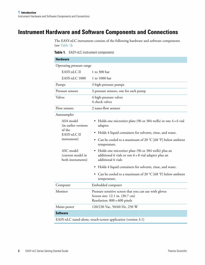
Instrument Hardware and Software Components and ConnectionsThe EASY-nLC instrument consists of the following hardware and software components (see Table 1).
Table 1. EASY-nLC instrument components
Hardware
Operating pressure range
EASY-nLC II 1 to 300 bar
EASY-nLC 1000 1 to 1000 bar
Pumps 3 high-pressure pumps
Pressure sensors 3 pressure sensors, one for each pump
Valves 4 high-pressure valves 4 check valves
Flow sensors 2 nano-flow sensors
Autosampler
ASA model (in earlier versions of the EASY-nLC II instrument)
• Holds one microtiter plate (96 or 384 wells) or one 4 × 6 vial adapter.
• Holds 4 liquid containers for solvents, rinse, and waste.
• Can be cooled to a maximum of 20 °C [68 °F] below ambient temperature.
ASC model (current model in both instruments)
• Holds one microtiter plate (96 or 384 wells) plus an additional 6 vials or one 6 × 8 vial adapter plus an additional 6 vials
• Holds 4 liquid containers for solvents, rinse, and waste.
• Can be cooled to a maximum of 20 °C [68 °F] below ambient temperature.
Computer Embedded computer
Monitor Pressure sensitive screen that you can use with glovesScreen size: 12.1 in. (30.7 cm) Resolution: 800 × 600 pixels
Mains power 120/230 Vac, 50/60 Hz, 250 W
Software
EASY-nLC stand-alone, touch-screen application (version 3.1)

1 IntroductionInstrument Hardware and Software Components and Connections
Thermo Scientific EASY-nLC Series Getting Started Guide 3
Installing the EASY-nLC instrument as part of an LC/MS system requires only four connections:
• Solvent outlet connection to the mass spectrometer’s ion source
• Power cable connection to a grounded line power source
• Contact closure connection between the EASY-nLC instrument and the mass spectrometer (see “Connecting to the Mass Spectrometer through Contact Closure” on page 42)
• Ethernet connection between the EASY-nLC instrument’s built-in computer and an Internet access port (see “Setting Up the Ethernet Connection to the Support Server” on page 46)
To control the EASY-nLC instrument with the Thermo Xcalibur data system, you must also connect the EASY-nLC instrument to the data system computer.

1 IntroductionAutosampler Tray Compartment
4 EASY-nLC Series Getting Started Guide Thermo Scientific
Autosampler Tray CompartmentFigure 2 shows the tray compartment and the waste beaker for the ASC autosampler model. You can open the tray compartment door manually or by using the touch-screen controls.
Figure 2. Tray compartment for the current ASC model (viewed from above)
The tray compartment holds the sample tray and the wash bottles. The tray compartment for the ASC model holds an additional six vials. The compartment to the right of the tray compartment holds the waste beaker.
The autosampler draws solvent from wash bottle W3 to perform a standard wash and ejects the solvent into wash bottle W4, which contains the needle wash insert. The autosampler can also perform a custom wash using the solvents from wash bottles W1–W3.
Figure 3 shows the tray compartment for the ASA model autosampler.
Figure 3. Tray compartment for the earlier version of the EASY-nLC II instrument with an ASA model autosampler (viewed from above)
Six (6) extra vial positions for standards or regular samples
Waste bottle with wash insert for cleaning of the outside of the needle
Well plate (96 or 384) or vial (6 × 8) adapter
Three (3) positions for wash solvents
Waste beaker

1 IntroductionExternal Solvent Lines
Thermo Scientific EASY-nLC Series Getting Started Guide 5
External Solvent LinesTwo PEEKsil™ or nanoViper™ solvent lines exit from the slot in the right side instrument panel, and two low-pressure Teflon solvent lines exit through the solvent bottle holder on the top of the instrument. The Column Out line connects to the column assembly’s inlet, and the Waste In line connects to the column assembly’s venting Tee. The low-pressure solvent lines connect to the solvent A and solvent B reservoir bottles.
Figure 4 shows the right side panel of the EASY-nLC 1000 instrument.
Figure 4. Column Out and Waste In solvent lines and low-pressure, Teflon solvent lines
Column Out Waste In
Low-pressure, Teflon solvent lines
nanoViper solvent lines

1 IntroductionBack Panel
6 EASY-nLC Series Getting Started Guide Thermo Scientific
Back PanelThe system communication (as part of an LC/MS system), contact closure, and line power connections are on the instrument’s back panel (see Figure 5).
Figure 5. Back panel of the EASY-nLC 1000 instrument shipped from the factory in San Jose, California, U.S.A.
2012
IO
110-120V▼
220-240▼
LAN MONITOR
HARDDRIVE
LAN MAC ADDRESS: 00-6--E0-45-4E-28
P-BUS
IN3 OUT3 IN2 OUT2 IN1 OUT1
120/230 V : 50/60 Hz: 250 WFuse at 120 V– : T5 AL 250 VFuse at 230 V– : T2.5 AL 250 V
USB RS-232
Ethernet connection
Contact closure pins
Power entry module
Serial number and part number

1 IntroductionBack Panel
Thermo Scientific EASY-nLC Series Getting Started Guide 7
Table 2 lists the function of each back panel element.
Table 2. Back panel elements from top to bottom and left to right
Element Description
USB Port for keyboard or mouse or removable USB storage device, two (2) provided
LAN For 10/100 MB/sec Ethernet connection
RS-232 For communication with add-on devices, for example a syringe drive
MONITOR Output for connection of external display
P-BUS For communication with add-on devices
IN/OUT pins Contact closure (primarily for communication with the mass spectrometer)
LAN MAC ADDRESS MAC address of the embedded computer (Gives the EASY-nLC instrument a unique network identifier on your local network.)
I|O Power switch
Fuse holder below I|O switch
Replaceable fuse ratings:• For 120 V, T 5 AL, 250 V• For 230 V, T 2.5 AL, 250 V
S/N Instrument serial number
P/N Product order code

1 IntroductionColumn Setup Options
8 EASY-nLC Series Getting Started Guide Thermo Scientific
Column Setup OptionsTwo solvent lines exit from the right side of the instrument. Behind the instrument’s right panel, the solvent line labeled Column Out connects to port 4 of valve S and the solvent line labeled Waste In connects to port 2 of valve W.
The fittings and columns that ship with the EASY-nLC instruments are suitable for the NanoFlex™ ion source. If your LC/MS system has an EASY-Spray™ ion source, use an EASY-Spray column and a precolumn with nanoViper fittings to create a two-column assembly (see Figure 66 on page 101). For information about setting up the column assemblies for the NanoFlex and EASY-Spray ion sources, see “Setting Up the Column Assembly” on page 90.
Because the pressure ranges differ between the EASY-nLC II and the EASY-nLC 1000 instrument model, the fittings used to make the plumbing connections and the columns depend on the instrument model.
You can connect the EASY-nLC instrument and enable the EASY-nLC software for these column configurations:
• “Two-Column Setup,” on this page
• “One-Column Setup” on page 9
Two-Column Setup
A two-column setup consists of a precolumn and an analytical column.
Figure 6 and Figure 7 show the two-column assemblies for the Nanospray Flex™ ion source and the EASY-nLC 1000 and EASY-nLC II instruments, respectively.
Tip When you install the two-column assembly, make sure that the One Column Setup check box is clear in the EASY-nLC device section on the Devices page of the Maintenance menu (see “Setting Up the Properties for the HPLC Device” on page 76).
When the One Column Setup check box is clear (not selected), valve W moves to position 1–6 during the sample loading step. Excess solvent A exits the venting Tee and passes through valve W to the waste beaker.
Note The EASY-nLC instruments ship with nanoflow LC columns for both ion sources. When installing the EASY-nLC instrument, a Thermo Fisher Scientific field service engineer uses the appropriate column to test the instrument performance.

1 IntroductionColumn Setup Options
Thermo Scientific EASY-nLC Series Getting Started Guide 9
Figure 6. Two-column assembly for the EASY-nLC 1000 instrument with a Nanospray Flex ion source
Figure 7. Two-column components for the EASY-nLC II instrument with a Nanospray Flex ion source
One-Column Setup
A one-column setup consists of an analytical column, the venting Tee, and a union and sleeve connection to an emitter. The Column Out solvent line and the analytical column connect to parallel legs of the venting Tee. The Waste In solvent line connects to the perpendicular leg of the Tee.
FlowFlow
VICI
Precolumn
Venting Tee PEEK™ union
Analytical column
Stainless steel union
EA
SY-C
olumn
Analytical
EA
SY-C
olumn
Pre-colum
n
Precolumn
Venting Tee
Analytical column
Tip When you install a one-column setup, select the One Column Setup check box in the EASY-nLC device section on the Devices page of the Maintenance menu (see “Setting Up the Properties for the HPLC Device” on page 76).
When the One Column Setup check box is selected, valve W remains in the 1–2 position during the sample loading step. Excess solvent A exits through the emitter tip.

1 IntroductionColumn Setup Options
10 EASY-nLC Series Getting Started Guide Thermo Scientific
Figure 8 and Figure 9 show the one-column assembly for the NanoFlex source and the EASY-nLC 1000 instrument and the EASY-nLC II instrument, respectively.
Figure 8. One-column setup for the EASY-nLC 1000 instrument and the Nano Flex source
Figure 9. One-column setup for the EASY-nLC II instrument and the Nano Flex source
IMPORTANT Make sure that you use the venting Tee for the one-column setup as well as for the two-column setup. Inside the instrument housing, the other end of the Waste In line connects to port 2 of valve W. During the Prepare Gradient step of a sample run, valve W provides pressurized venting to the solvent system through the venting Tee. When the Waste In line is not connected to the venting Tee, the system pressure can only vent through the analytical column. Because venting through the column takes longer than venting through the Tee, the total run time is significantly longer than if you used the venting Tee for a one-column setup.
Flow
VICI
Venting Tee
Waste In line
Column Out line
Analytical column
EmitterUnion
Sleeves
EA
SY-C
olumn
Analytical
Venting Tee
Waste In line
Column Out line
Analytical column
EmitterUnion
Sleeves

1 IntroductionSolvent System Components
Thermo Scientific EASY-nLC Series Getting Started Guide 11
Solvent System ComponentsThe EASY-nLC solvent system has three syringe pumps (A, B, and S); three pressure sensors, one for each pump; two flow sensors, one for pump A and one for pump B; four rotary valves (A, B, S, and W); two check valve assemblies, one for solvent A and one for solvent B; and a mixing Tee where solvents A and B are mixed under high pressure.
These topics describe the hardware components of the solvent system:
• “Syringe Pumps,” on this page
• “Pressure Sensors,” on this page
• “Flow Sensors” on page 12
• “Six-Port Rotary Valves” on page 13
• “Check Valve Assemblies” on page 14
• “Mixing Tee” on page 14
Syringe Pumps
The syringe pumps perform these functions (see Table 3).
For maintenance purposes, the built-in instrument control software tracks the volume pumped by each pump. For information about recording maintenance for the pumps, refer to the EASY-nLC Series Troubleshooting and Maintenance Guide.
Pressure Sensors
The three pressure sensors are connected to the solvent path between the syringe pump outlets and the six-port, three-position valves.
Using the strain gauge principle to measure pressure accurately, the pressure sensors are flow-through, zero dead volume devices with a wetted path that contains 12 μL of swept volume. The pressure sensors for the EASY-nLC II instrument have an operating range of 0 to 5000 psi (345 bar), and the pressure sensors for the EASY-nLC 1000 instrument have an operating range of 0 to 15 000 psi (1034 bar).
Table 3. Syringe pump functions
Component Function
Pumps A and B Draw solvent from the solvent bottles on top of the instrument, empty solvent to the waste beaker in the compartment to the right of the autosampler tray compartment, and deliver solvent to the mixing Tee.
Pump S Draws solvent from the W3 bottle, draws sample from the specified sample location into the needle, and empties solvent to the W4 bottle in the autosampler tray compartment.

1 IntroductionSolvent System Components
12 EASY-nLC Series Getting Started Guide Thermo Scientific
Flow Sensors
Two flow sensors provide feedback control for pumps A and B. The two flow sensors are liquid mass flow meters with a patented technology. Each flow meter consists of a length of fused silica capillary, a sensor chip, a heating resistor, and two temperature sensors (see Figure 10).
Figure 10. Flow sensor schematic
The flow sensors determine the flow rate of solvents passing through the solvent system by measuring the heat transfer through the fused silica capillary. Outside the capillary, a heating resistor on a thermally optimized membrane is maintained above ambient temperature. When liquid flows through the capillary, the temperature distribution upstream and downstream of the heating resistor is disturbed. The two temperature sensors measure this temperature asymmetry.
Because the temperature distribution depends on both the solvent flow rate and the solvent mixture, you must recalibrate the flow sensors whenever you change the solvent types for solvents A and B. For example, if you use methanol instead of acetonitrile for the solvent B mixture, recalibrate the flow sensors as described in the EASY-nLC Series Troubleshooting and Maintenance Guide.
The EASY-nLC 1000 instrument uses two flow sensors with a maximum measuring range of 5 μL/min. The EASY-nLC II instrument uses two different flow sensors. The maximum measuring range is approximately 2.9 μL/min for flow sensor A and 4.5 μL/min for flow sensor B.
Tip When the flow rate produced by pump A or B exceeds the maximum measuring range of the respective flow sensor, use the pump position readback (x.x /140 μL) above the pump graphic to monitor the flow rate.
Flow
Sensor chip
Heater
Temperature sensors
Tubing
Based on CMOSens™ TechnologyPrinciple patented: US Pat. 6 813 944

1 IntroductionSolvent System Components
Thermo Scientific EASY-nLC Series Getting Started Guide 13
Six-Port Rotary Valves
The six-port rotary valves can be in three different positions: 1–2 position, 1–6 position, and centered (see Figure 11).
Figure 11. Valve positions
For maintenance purposes, the built-in instrument control software tracks the number of valve shifts for each valve. For information about checking and resetting the devices usage counters, refer to the EASY-nLC Series Troubleshooting and Maintenance Guide.
Depending on the valve position, the rotary valves perform these functions (see Table 4).
1–2 position 1–6 position Centered
1
4
2 6
3 5
1
4
2 6
3 5
1
4
2 6
3 5
Table 4. Rotary valve functions (Sheet 1 of 2)
Valve Function
A and B Direct the solvent flow from syringe pump A and B, respectively.
1–2 position Directs the solvent flow toward the check valve. When the rotary valve is in the 1–2 position, the pump draws solvent from the solvent bottle on top of the instrument or empties solvent to the waste beaker.
1–6 position Directs the solvent flow toward the mixing Tee.
Centered • Prevents backflow into the solvent line upstream of the mixing Tee.
• Allows the back pressure for the solvent A and B lines to equalize before the gradient step of a sample run.
• Provides back pressure for several maintenance scripts.
S Directs the solvent flow from syringe pump S and the solvent flow from the mixing Tee.
1–2 position The solvent flow bypasses the sample loop.
1–6 position The solvent flow passes through the sample loop.
Centered • Provides back pressure for the Flush Air script for pump S.
• Provides back pressure for the system leak test.
• Shuts off the flow to the Column Out line and provides back pressure during the Flow Sensor Calibration script.
1 IntroductionSolvent System Components
14 EASY-nLC Series Getting Started Guide Thermo Scientific
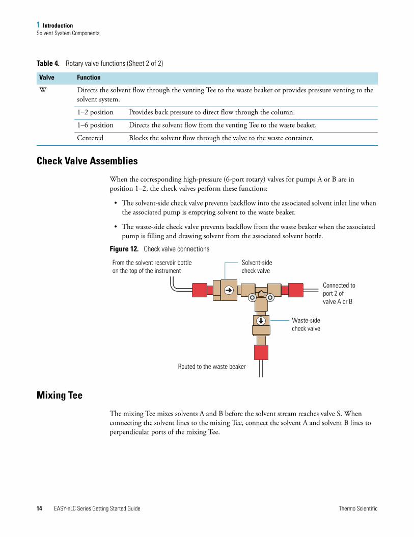
Check Valve Assemblies
When the corresponding high-pressure (6-port rotary) valves for pumps A or B are in position 1–2, the check valves perform these functions:
• The solvent-side check valve prevents backflow into the associated solvent inlet line when the associated pump is emptying solvent to the waste beaker.
• The waste-side check valve prevents backflow from the waste beaker when the associated pump is filling and drawing solvent from the associated solvent bottle.
Figure 12. Check valve connections
Mixing Tee
The mixing Tee mixes solvents A and B before the solvent stream reaches valve S. When connecting the solvent lines to the mixing Tee, connect the solvent A and solvent B lines to perpendicular ports of the mixing Tee.
W Directs the solvent flow through the venting Tee to the waste beaker or provides pressure venting to the solvent system.
1–2 position Provides back pressure to direct flow through the column.
1–6 position Directs the solvent flow from the venting Tee to the waste beaker.
Centered Blocks the solvent flow through the valve to the waste container.
Table 4. Rotary valve functions (Sheet 2 of 2)
Valve Function
From the solvent reservoir bottle on the top of the instrument
Routed to the waste beaker
Waste-sidecheck valve
Solvent-sidecheck valve
Connected to port 2 ofvalve A or B

1 IntroductionPredefined Steps for Sample Runs
Thermo Scientific EASY-nLC Series Getting Started Guide 15
Predefined Steps for Sample RunsDuring sample runs, the EASY-nLC instrument goes through a series of predefined steps. These topics describe the sequence of events that occur during a sample run. The first topic provides a brief overview of the sample steps and the second topic provides a more illustrative explanation of each step.
• “Overview of a Sample Run,” on this page
• “Sequence of Events for Each Step of a Sample Run” on page 18
Overview of a Sample Run
During sample runs, the active steps are highlighted in bold on the Home > Overview page (see Figure 13).
Figure 13. Current step area of the Home > Overview page
To minimize the cycle time, the instrument runs these steps in parallel:
• Refill A and B and Pickup Sample
• Column Equilibration and Pickup Sample
• Gradient and Autosampler Wash + Refill S
Load sample Equilibrate precolumnPrealign A + B Equilibrate analytical columnGradient Autosampler wash + refill S
Pickup sample Initialize system Refill AB

1 IntroductionPredefined Steps for Sample Runs
16 EASY-nLC Series Getting Started Guide Thermo Scientific
Table 5 summarizes the steps of a sample run.
Table 5. Sample run steps
Step Action
Refill A B Pumps A and B draw solvent from the solvent bottles on top of the instrument.
Precolumn and analytical column equilibration
Pump A delivers solvent to the system. For a two-column system, solvent A passes through the precolumn and then out to the waste beaker. After the precolumn equilibration finishes, valve W switches to position 1–2 to direct the solvent flow through the analytical column.
Pickup sample The autosampler moves the needle to the sample position specified in the batch table (injection sequence). Then pump S aspirates sample from the specified vial or well position into the sample loop attached to valve S.
Load sample With valve S in position 1–6, pump A delivers solvent to the system, flushing sample out of the sample loop and onto the precolumn or the analytical column. Valve W is in position 1–6 for a two-column system and position 1–2 for a one-column system.
Prealign A + B (Prepare Gradient)
The system vents through the Waste In line or builds up pressure to a precalculated pressure. Pump B builds up pressure to match the precalculated pressure of pump A. Pump B pumps a fixed volume of solvent B into the loop to ensure the alignment of solvents at the mixing Tee. Then valves S and W switch to position 1–2. With valves S and W in position 1–2, the solvent flow bypasses the sample loop and is directed through the column.
Gradient Pumps A and B deliver solvent to the system. As the percent composition of solvent B increases, analytes elute off the column or columns.
Autosampler wash + refill S
Pump S draws solvent from one or more wash bottles, washes the autosampler needle and the sample loop, and then refills.

1 IntroductionPredefined Steps for Sample Runs
Thermo Scientific EASY-nLC Series Getting Started Guide 17
Figure 14 shows a flow chart of the sample run steps.
Figure 14. Flow chart of the sample run steps
Initialize system—check that the hardware is ready.
Refill pump A. Refill pump B. Pick up sample.
Equilibrate precolumn
(for a two-column setup).
Equilibrate analytical column.
Load sample.
Prepare gradient.
Run gradient.Autosampler wash and refill pump S.
1 IntroductionPredefined Steps for Sample Runs
18 EASY-nLC Series Getting Started Guide Thermo Scientific
Sequence of Events for Each Step of a Sample Run
These topics explain and illustrate each step in a sample run:
• “Refill Pumps A and B,” on this page
• “Pickup Sample Step” on page 20
• “Column Equilibration Steps” on page 22
• “Load Sample Step” on page 24
• “Prepare Gradient Step” on page 26
• “Gradient Step” on page 29
• “Autosampler Wash Step” on page 30
Refill Pumps A and B
The instrument refills pumps A and B. With valves A and B in the 1–2 position, the corresponding check valves control the direction of the solvent flow (see Figure 15). When the pump begins to draw solvent from the solvent bottle, the corresponding check valve assembly opens to the solvent bottle and closes to the waste beaker.
As pumps A and B are refilling, the autosampler needle moves to the sample location specified in the acquisition sequence. Pump S draws sample from the sample vial or microplate well and pulls the sample into the sample loop attached to valve S.

1 IntroductionPredefined Steps for Sample Runs
Thermo Scientific EASY-nLC Series Getting Started Guide 19
Figure 15. Valves A and B in position 1–2 and pumps A and B in fully retracted position
1
4
2 63 5W
1
4
2 63 5A
1
4
2 63 5B
1
4
2 63 5S
↓ ↓
Waste beaker
Pump S Pump A Pump B
Check valve assembly A
Check valve assembly B
Solvent A Solvent B
Waste In line
ColumnOut line
Flow sensor A Flow sensor B
Mixing Tee
Autosampler needle

1 IntroductionPredefined Steps for Sample Runs
20 EASY-nLC Series Getting Started Guide Thermo Scientific
Pickup Sample Step
The Pickup Sample step includes this sequence of actions.
Figure 16 through Figure 18 show pump S drawing the first air segment, the requested sample pickup volume of 10 μL, and the second air segment. At the end of the Pickup Sample step, the sample loop holds the requested sample volume of 10 μL, two 1 μL air segments, and approximately 8 μL of solvent A.
Action
1 Pump S moves to a fixed position (filled with approximately 100 μL of solvent for an instrument with a 20 μL sample loop) by either dispensing excess solvent to the W4 bottle or drawing solvent from the W3 bottle.
2 Pump S draws 1 μL of air into the needle.
3 The XYZ robot moves the needle holder to the specified sample vial or microplate well location.
4 The needle descends into the sample solution.
5 Pump S draws the requested sample pickup volume into the needle.
Note The EASY-nLC instrument performs only partial loop injections. To avoid drawing sample into pump S, the application prevents you from entering a sample pickup volume larger than the sample loop size minus two microliters. The extra two microliters are required for the two air segments that bracket the sample.
6 The XYZ robot raises the needle out of the sample solution.
7 To transfer the sample into the loop, pump S draws a fixed volume of air into the needle. This fixed volume of air (~10.25 μL) is equal to the needle volume plus the valve port-to-port volume plus an additional 1 μL of air to bracket the sample solution inside the loop.

1 IntroductionPredefined Steps for Sample Runs
Thermo Scientific EASY-nLC Series Getting Started Guide 21
Figure 16. Pickup Sample step—with pump S drawing the front air segment into the needle
Figure 17. Pickup Sample step—with pump S drawing 10 μL of sample from a sample vial
Figure 18. Pickup Sample step—with the requested sample volume loaded into the loop and bracketed by two air segments
1
4
2 63 5S
80 40 0120
W3 bottle W4 bottle Samplevial
Pressure sensor
Pump S
From the mixing TeeColumn Out line
Air segment
1
4
2 63 5S
80 40 0120
W3 bottle W4 bottle Samplevial
Pump S
Pressure sensor
From the mixing TeeColumn Out line
1 μL front air segment
1
4
2 63 5S
80 40 0120
W3 bottle W4 bottle Samplevial
Pressure sensor
Pump S
From the mixing TeeColumn Out line
1 μL rear air segment
1 μL front air segment

1 IntroductionPredefined Steps for Sample Runs
22 EASY-nLC Series Getting Started Guide Thermo Scientific
Column Equilibration Steps
For a one-column setup, the sample run includes the analytical column equilibration step. For a two-column setup, the sample run includes both a precolumn equilibration step and an analytical column equilibration step.
The Equilibrate Precolumn step (see Figure 19) includes this sequence of actions.
The analytical column equilibration step includes this sequence of actions.
Action
1 Valve A and valve W switch to position 1–6. Valve B switches to the centered position. Valve S switches to position 1–2.
2 Pump A pushes the specified solvent volume through the precolumn at the specified pressure or flow rate. Excess solvent A exits the venting Tee and passes through valve W to the waste beaker.
Action
1 For a two-column setup, valve A remains in position 1–6, valve B remains in the centered position, and valve S remains in position 1–2. Valve W switches to position 1–2.
For a one-column setup, valve A switches to position 1–6. Valve B switches to the centered position. Valve S switches to position 1–2. Valve W switches to position 1–2.
2 Pump A pushes the specified solvent volume through the analytical column at the specified pressure or specified flow rate.

1 IntroductionPredefined Steps for Sample Runs
Thermo Scientific EASY-nLC Series Getting Started Guide 23
Figure 19. Equilibrate Precolumn step
1
4
2 63 5W
1
4
2 63 5A
1
4
2 63 5B
1
4
2 63 5S
Pump B
Pump A
FlowFlow
Pressure sensor
Waste beaker
Pressure sensor
Flowsensor
Flowsensor
Column Out line
Pump A
Pump B
To the autosampler needle
Mixing Tee
Waste In lineVenting Tee
Precolumn
Analyticalcolumn
1 IntroductionPredefined Steps for Sample Runs
24 EASY-nLC Series Getting Started Guide Thermo Scientific
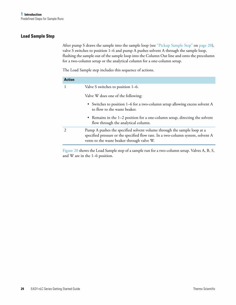
Load Sample Step
After pump S draws the sample into the sample loop (see “Pickup Sample Step” on page 20), valve S switches to position 1–6 and pump A pushes solvent A through the sample loop, flushing the sample out of the sample loop into the Column Out line and onto the precolumn for a two-column setup or the analytical column for a one-column setup.
The Load Sample step includes this sequence of actions.
Figure 20 shows the Load Sample step of a sample run for a two-column setup. Valves A, B, S, and W are in the 1–6 position.
Action
1 Valve S switches to position 1–6.
Valve W does one of the following:
• Switches to position 1–6 for a two-column setup allowing excess solvent A to flow to the waste beaker.
• Remains in the 1–2 position for a one-column setup, directing the solvent flow through the analytical column.
2 Pump A pushes the specified solvent volume through the sample loop at a specified pressure or the specified flow rate. In a two-column system, solvent A vents to the waste beaker through valve W.

1 IntroductionPredefined Steps for Sample Runs
Thermo Scientific EASY-nLC Series Getting Started Guide 25
Figure 20. Load Sample step (two-column setup)
1
4
2 63 5W
1
4
2 63 5A
1
4
2 63 5B
1
4
2 63 5S
Pump B
Pump AFlow
Flow
Pressure sensor
Waste beaker
Pressure sensor
Flowsensor
Flowsensor
Column Out line
Pump A
Pump B
Mixing Tee
Waste In line Venting Tee
Precolumn
Analyticalcolumn
Centered
Rear air segment
Solvent B
Solvent A
Sample
Sample

1 IntroductionPredefined Steps for Sample Runs
26 EASY-nLC Series Getting Started Guide Thermo Scientific
Prepare Gradient Step
Before the gradient begins, this sequence of actions occurs.
Figure 21 shows 0.5 μL of solvent B being pumped toward valve S during the Prepare Gradient step. Figure 22 shows 0.4 μL of solvent A being pumped toward valve S during the Prepare Gradient step.
Action
1 The built-in instrument control software calculates the volume of solvent A required to complete the gradient program. Pump A refills if it does not contain a sufficient volume of solvent to complete the gradient program.
2 With valves A, W, and S in position 1–6 and valve B in the centered position, the system vents through the Waste In line to a precalculated pressure, or increases the pressure to the precalculated pressure with valve W in position 1–2.
Pump B builds up pressure to match the precalculated pressure of pump A.
3 Valve B switches to position 1–6. If valve W was in position 1–2 in the previous step, it also switches to position 1–6. The Intelligent Flow Control (IFC™) system now controls pumps A and B at the precalculated pressure.
With all of the valves in position 1–6, pump B pumps a fixed volume of 0.5 μL of solvent B toward valve S to ensure correct alignment of solvents A and B up to valve S. See Figure 21.
4 Valve W switches to position 1–2. The Automated Flow Control (AFC™) system now controls pumps A and B.
To align solvents A and B up to valve S, the system delivers a gradient consisting of a minimum of 2% solvent B or the gradient start solvent B%, whichever is higher, until it pumps 0.4 μL of solvent A into the sample loop (see Figure 22).
5 Valve S moves to position 1–2, which allows the mobile phase to bypass the sample loop, and the instrument sends the closure signal to the mass spectrometer.
Note During the Prepare Gradient step, a slight amount of solvent B enters the sample loop. This does not affect the next run because the Autosampler Wash step flushes the sample loop before the next run starts.

1 IntroductionPredefined Steps for Sample Runs
Thermo Scientific EASY-nLC Series Getting Started Guide 27
Figure 21. Excess 0.5 μL of solvent B pumped toward valve S during the Prealign Gradient step
1
4
2 63 5W
1
4
2 63 5A
1
4
2 63 5S
1
4
2 63 5B Flow
Flow
Pressure sensor
Waste beaker
Pressure sensor
Flowsensor
Flowsensor
Pump A
Pump B
Mixing Tee
Solvent B
Solvent A

1 IntroductionPredefined Steps for Sample Runs
28 EASY-nLC Series Getting Started Guide Thermo Scientific
Figure 22. The system pumps a mixture of 2% solvent B or higher until it pumps 0.4 μL of solvent A.
1
4
2 63 5A
1
4
2 63 5S
1
4
2 63 5B
1
4
2 63 5W
FlowFlow
Pressure sensor
Waste beaker
Pressure sensor
Flowsensor
Flowsensor
Pump A
Pump B
Mixing Tee
Solvent B
Solvent A

1 IntroductionPredefined Steps for Sample Runs
Thermo Scientific EASY-nLC Series Getting Started Guide 29
Gradient Step
The gradient step includes this sequence of actions.
Figure 23 shows the gradient step of a sample run. Mobile phase from the mixing Tee bypasses the sample loop as it enters and exits valve S through ports 4 and 3, respectively.
Figure 23. Gradient step with valve A and valve B in position 1–6 and autosampler wash step with valve S in position 1–2
Action
1 The instrument runs the gradient program.
Note With valve S in position 1–2, the mobile phase bypasses the sample loop during the gradient program. Therefore, the sample loop does not add any gradient delay volume to the system.
2 If either pump runs out of solvent during the gradient run, both pumps refill. The refilling process takes approximately 2 minutes.
1
4
2 63 5W
1
4
2 63 5A
1
4
2 63 5S
1
4
2 63 5B
FlowFlow
Flowsensor
Pressure sensor
Pressure sensor
Flowsensor
Column Out line
Pump A
Pump B
Sample loop
Mixing Tee
Waste In line
Solvent B
Solvent A

1 IntroductionPredefined Steps for Sample Runs
30 EASY-nLC Series Getting Started Guide Thermo Scientific
Autosampler Wash Step
The standard autosampler wash step includes this sequence of actions.
The Autosampler Wash and Refill S step occurs in parallel with the Gradient step.
Figure 24. Autosampler wash step with valve S in position 1–2
Action
1 The autosampler needle moves to the W4 bottle.
2 Pump S pushes the specified volume of solvent through the sample loop and needle. As the wash solvent exits the needle, it overfills the needle insert and washes the exterior surface of the needle. See Figure 24.
3 Pump S refills with solvent A from the W3 bottle.
1
4
2 63 5S
Pressure sensor
Column Out line
Pump S
Autosampler needle
Sample loop
W3 bottle W4 bottle
Mixing Tee
Solvent B
Solvent A

1 IntroductionPump Flow Control
Thermo Scientific EASY-nLC Series Getting Started Guide 31
Pump Flow ControlThe EASY-nLC instrument contains split-free, high-pressure syringe pumps capable of delivering flows from 1 nL/min to 300 μL/min.
These flow control systems optimize the instrument performance:
• “Automatic Flow Control System,” on this page
• “Intelligent Flow Control” on page 32
• “Load Speed Protection” on page 33
Automatic Flow Control System
The Automatic Flow Control (AFC) system (see Figure 25) is active during these processes:
• The gradient step of a sample run
• The execution of the isocratic flow maintenance script
The AFC system uses the output of the flow sensors to regulate the flow and accurately maintain the programmed flow from each channel, even during sudden pressure changes caused by solvent composition changes. For accuracy, the AFC system requires a minimum pressure of 20 bar.
Figure 25. Schematic diagram of the AFC system
1
4
2 63 5B
1
4
2 63 5A
AFCTM
Pump A
Flow sensor A
Pump B
Pressuresensor A
Flow sensor B
A/B mixing Tee
Pressuresensor B

1 IntroductionPump Flow Control
32 EASY-nLC Series Getting Started Guide Thermo Scientific
Intelligent Flow Control
The Intelligent Flow Control (IFC™) system (see Figure 26) is active during these processes:
• The column equilibration and sample loading steps of a sample run
• The first part of the prepare gradient step for pumps A and B
• The execution of the precolumn equilibration, analytical column equilibration, leak, and back pressure scripts
The IFC system uses output from both the flow sensors and pressure sensors A and B to regulate the flow from pumps A and B. By controlling the flow rate with both a flow and pressure feedback system, the IFC system enhances system performance as follows:
• Reduces the loss of productivity caused by instrument stoppage related to overpressure (for instance, stoppage caused by viscous samples during the sample loading step).
• Uses the pressure range of the instrument more effectively. For example, when you set a maximum pressure for the sample loading and column equilibration steps instead of a flow rate, the system automatically adjusts the flow rate to the maximum acceptable value.
• Builds the pressure rapidly during the prepare gradient step.
Figure 26. Schematic diagram of the IFC system
1
4
2 63 5A
1
4
2 63 5B
IFCTM
Pump A
Flow sensor A
Pump B
Pressuresensor A
Flow sensor B
A/B mixing Tee
Pressuresensor B

1 IntroductionPump Flow Control
Thermo Scientific EASY-nLC Series Getting Started Guide 33
You can program the column equilibration and sample loading steps as follows:
• Specify both a set flow and a maximum pressure. The setting reached first (which becomes the limiting parameter) depends on the dimensions of the attached column or columns. If the system reaches the set pressure before it reaches the set flow rate, the IFC system reduces the flow rate to maintain the pressure. If the system reaches the set flow rate before the pressure limit, the pump maintains the set flow rate.
• Specify only a set flow. The IFC system maintains the set flow rate unless the pressure exceeds the maximum system pressure.
• Specify only a maximum pressure. The IFC system adjusts the flow rate to maintain the set pressure.
The duration of both the equilibration and loading steps depends on the total volume of solvent specified and the actual flow rate. When the set pressure is the limiting factor, the system adjusts the actual flow rate, which varies the duration of these steps.
Load Speed Protection
When the Load Speed Protection system (LSP) is on, the batch run stops if the system reaches the set max pressure before it reaches the set flow during the sample loading step. Stopping the batch run when the system pressure rises above an acceptable level prevents the system from running the remaining samples when the column or tubing has become clogged.
For instructions about how to turn on the Load Speed Protection system, see “Setting Up the Properties for the HPLC Device” on page 76.
Tip If the duration of the equilibration and loading steps must be fixed, limit these steps by flow rather than by pressure. Use the appropriate precolumn and analytical column maintenance scripts to determine the appropriate flow rates for your LC columns.


Thermo Scientific EASY-nLC Series Getting Started Guide 35
2
Installing the EASY-nLC Instrument
To install the EASY-nLC instrument or move the instrument from one laboratory benchtop to another, follow the installation instructions in this chapter after reviewing the “Safety and Special Notices” on page ix.
Note This chapter describes the laboratory requirements and the back panel connections for the EASY-nLC instrument as a stand alone LC system or as an inlet to a mass spectrometer.
• For information about installing the LC columns, the sample plates, the solvent bottles, and the wash bottles, see Chapter 5, “Preparing the EASY-nLC Instrument for Use.”
• For information about connecting the column assembly to the mass spectrometer’s ion source, refer to the manual provided with the ion source.
• For information about the internal solvent lines, refer to the EASY-nLC Series Troubleshooting and Maintenance Guide.
Contents
• Lifting Instructions
• Laboratory Requirements
• Back Panel Connections

2 Installing the EASY-nLC InstrumentLifting Instructions
36 EASY-nLC Series Getting Started Guide Thermo Scientific
Lifting InstructionsThe instrument weighs 32 kg (71 lb)35 kg (77.2 lb). For safety reasons, use two people to move the instrument to a table cart for transport and wear gloves.
Figure 27 shows the lift points for the EASY-nLC instrument. With one person on each side of the instrument, lift the instrument from the bottom with one hand while stabilizing the top portion of the instrument with the other hand.
Figure 27. Lifting the EASY-nLC II instrument by hand
CAUTION At 32 kg (71 lbs)35 kg (77.2 lb), the EASY-nLC instrument is too heavy for one person alone to lift. When moving the instrument, use two people to place it on a table cart for transport.
CAUTION Before you move the EASY-nLC instrument from one benchtop to another, close down the EASY-nLC instrument (see “Closing Down the EASY-nLC Instrument” on page 64), disconnect the EASY-nLC instrument from line power, the detector, and the data system computer (if applicable). For information about installing or removing the column assembly from the mass spectrometer’s ion source, refer to the manual provided with the ion source.
EASY - nLC II

2 Installing the EASY-nLC InstrumentLaboratory Requirements
Thermo Scientific EASY-nLC Series Getting Started Guide 37
Laboratory RequirementsThe following topics describe the laboratory requirements for the EASY-nLC instrument. For more information about the requirements for the EASY-nLC instrument, refer to the EASY-nLC Series Preinstallation Requirements Guide. For information about the preinstallation requirements for a Thermo Scientific mass spectrometer, refer to its preinstallation requirements guide.
• “Benchtop Requirements,” on this page
• “Internet Access” on page 39
• “Power and Fuse Requirements” on page 39
• “Temperature and Humidity Requirements” on page 39
Benchtop Requirements
Place the EASY-nLC instrument on a benchtop or movable table that can support a minimum of two times the instrument weight. For the EASY-nLC instrument, make sure that the table can support a minimum of 70 kg (154 lb).
Table 6 lists the dimensions of the EASY-nLC II and EASY-nLC 1000 instruments. Allow for at least 15 cm (6 in.) of free space at the back of the instrument for proper air circulation.
To minimize extra column volume between the LC column outlet and the detector inlet, place the EASY-nLC instrument as close as possible to the high-performance liquid chromatography (HPLC) detector, mass spectrometer, or both. However, to avoid exposure to direct heat, place the EASY-nLC instrument away from any detector or mass spectrometer vents.
Figure 28 shows a typical benchtop setup for an EASY-nLC instrument connected to a Thermo Scientific mass spectrometer. Connecting the data system computer to your local area network (intranet) requires an additional network card.
Using the setup shown in Figure 28, you can control the EASY-nLC instrument from the local data system computer or from another data system computer on the intranet; however, the EASY-nLC instrument might not be able to communicate with the remote support server. For information about connecting the EASY-nLC instrument to the remote support server, see “Setting Up the Ethernet Connection to the Support Server” on page 46.
Table 6. EASY-nLC instrument dimensions
Dimension EASY-nLC II EASY-nLC 1000
Width 35 cm (13.8 in.) 36 cm (14.2 in.)
Depth 38 cm (15.1 in.) 38 cm (15.1 in.)
Height 45 cm (17.7 in.) 45 cm (17.7 in.)

2 Installing the EASY-nLC InstrumentLaboratory Requirements
38 EASY-nLC Series Getting Started Guide Thermo Scientific
Figure 28. EASY-nLC instrument and LTQ™ Series MS detector setup
CAUTION Before you move the EASY-nLC instrument from one benchtop to another, close down the EASY-nLC instrument (see “Closing Down the EASY-nLC Instrument” on page 64), disconnect the EASY-nLC instrument from line power, the detector, and the data system computer (if applicable). For information about installing or removing the column assembly from the mass spectrometer’s ion source, refer to the manual provided with the ion source.
Note Figure 28 shows the EASY-Spray source, which requires an additional power outlet.
Inject
Load
Waste
Detector
Vacuum Communication System ScanningPower
Pump On
EASY - nLC IIEASY - nLC 1000
Solvent lines
Intranet connection(Ethernet jack)
Ethernet cable from the MS detector to the Ethernet switch
Ethernet cable from the EASY-nLC instrumentto the Ethernet switch
Ethernet cable from the Ethernet switchto the data system computer
Contact closure cable from the EASY-nLC instrument to the MS detector
Data system computer
EASY-nLC 1000instrument
Ion sourcemonitor
LTQ SeriesMS detector
Ethernetswitch
Power lineconnection

2 Installing the EASY-nLC InstrumentLaboratory Requirements
Thermo Scientific EASY-nLC Series Getting Started Guide 39
Internet Access
For online support and monitoring (remote support), provide Internet access for the EASY-nLC instrument within reach of the laboratory benchtop.
Power and Fuse Requirements
Use the EASY-nLC instrument only with properly grounded appliances and power sources.
You can plug the EASY-nLC instrument into these grounded line power sources:
• 120 Vac, 50/60 Hz, 250 W
• 230 Vac, 50/60 Hz, 250 W
The fuse requirements for the EASY-nLC instrument are as follows:
• For 120 Vac, one T 5 AL 250 V fuse (5 × 20 mm, IEC 60127)
• For 230 Vac, one T 2.5 AL 250 V fuse
All fuses supplied with the instrument are UL Listed and CSA certified.
Temperature and Humidity Requirements
Avoid locations with high air humidity or extreme changes in temperature (such as direct sunlight, drafts, directly below an air conditioning or heating vent, or directly next to the mass spectrometer or HPLC detector vent).
For optimal autosampler plate cooling, place the unit in an area where the working temperature is within 5 to 30 °C (41 to 86 °F).
The optimal humidity range is between 20 to 80% RH. Avoid condensing humidity.
IMPORTANT The EASY-nLC instrument uses Secure Shell (SSH™), a network protocol for secure data communication, to connect to the support server, which uses the Linux™ operating system. Port 22 is the standard TCP port for SSH programs.
To use the remote support feature, the firewalls for your local network must allow outgoing TCP/IP traffic from the EASY-nLC instrument to the support server at IP address 195.41.108.93, port 22.
Note To determine the appropriate rating for an uninterruptible power supply (UPS), assume 250 W.
Note Depending on the nanospray ion source, your nanospray system might need an additional power receptacle. The EASY-Spray ion source requires an additional power receptacle, whereas the NanoFlex ion source draws its line power from the mass spectrometer.

2 Installing the EASY-nLC InstrumentBack Panel Connections
40 EASY-nLC Series Getting Started Guide Thermo Scientific
Back Panel ConnectionsTo connect the EASY-nLC instrument to a mass spectrometer, the intranet within your facility, the Internet for remote support, and other peripheral hardware, follow these procedures:
• “Connecting to Line Power” on page 41
• “Connecting to the Mass Spectrometer through Contact Closure” on page 42
• “Connecting the Ethernet Communication Cables” on page 43
• “Attaching a Mouse and Keyboard to the USB Connections” on page 47
• “Attaching Add-on Devices through the P-Bus and RS-232” on page 47
Figure 29 shows an LC/MS system with an EASY-nLC instrument, an LTQ Series mass spectrometer, and a data system computer. The LC system, mass spectrometer, and data system hardware are connected to three separate fourplex outlets that are hardwired to a common protective earth ground. This figure does not show the monitoring system for the nanoflow ion source or the external rotary pumps for the mass spectrometer.
Figure 29. LC/MS system with an EASY-nLC instrument, an LTQ Series mass spectrometer, and a data system computer
IO
110-120V▼
220-240▼
This device complies with Part 15 of the FCC Rules.Operation is subject to the following two conditions:(1) This device may not cause harmful interference, and (2) This device must accept any interference received, including interference that may cause undersired operation.
This instrument is for research use only.
LAN MONITORPS/2
HARDDRIVE
DEVICE: EASY-NLC
P/N LC100LAN MAC ADDRESS: 00-6--E0-45-4E-28
Proxeon Biosystems A/SWeb: www.proxeon.comPhone +45 6557 2300 Fax +45 6557 2301
P-BUS
IN3 OUT3 IN2 OUT2 IN1 OUT1
PRO EON
120/230 V : 50/60 Hz: 250 WFuse at 120 V– : T5AL 250 VFuse at 230 V– : T2.5 AL 250 V
IO
110-120V▼
220-240▼
This device complies with Part 15 of the FCC Rules.Operation is subject to the following two conditions:(1) This device may not cause harmful interference, and (2) This device must accept any interference received, including interference that may cause undersired operation.
This instrument is for research use only.
LAN MONITOR
HARDDRIVE
DEVICE: EASY-NLC
P/N LC100LAN MAC ADDRESS: 00-6--E0-45-4E-28
Thermo Fisher Scientific A/SWeb: www.proxeon.comPhone +45 6557 2300 Fax +45 6557 2301
P-BUS
IN3 OUT3 IN2 OUT2 IN1 OUT1
120/230 V : 50/60 Hz: 250 WFuse at 120 V– : T5 AL 250 VFuse at 230 V– : T2.5 AL 250 V
USB RS-232
Power In
Mech. Pumps/Accessory
Main Power
Peripheral Control
Ethernet
Electronics Normal
Service Mode
Reset
Analog Input
StartIn
100 Base T
ReadyOut
1V MAX 10V MAX
StartOut
On230 V AC
15 A
A 5.5 MAX
A 5.5 MAX
Off
Data system computer and Ethernet switch
EASY-nLC instrument(back panel)
LTQ Series mass spectrometer(right panel)
Ethernet cablesFourplex outlet for the mass spectrometer
Contact closure cable
Laboratory LAN port
Fourplex outlet for the data system hardware
Fourplex outlet for the EASY-nLC system

2 Installing the EASY-nLC InstrumentBack Panel Connections
Thermo Scientific EASY-nLC Series Getting Started Guide 41
Connecting to Line Power
Each EASY-nLC instrument comes with a 2.5 m (8.2 ft) long power cord.
Installing an EASY-nLC instrument requires a minimum of one outlet. The electrical outlet must be earth ground hard-wired to the main panel.
If you are using the EASY-nLC instrument as an inlet to an MS detector, the LC/MS system might require two or more fourplex outlets. The interconnected electrical outlets for the LC/MS system and the data system computer must have a common point to one ground connector (see Figure 29 on page 40).
To connect the EASY-nLC instrument to line power
1. If you are moving an existing instrument from one benchtop to another, make sure that the fuse is installed correctly.
For information about installing the fuse, refer to the EASY-nLC Series Troubleshooting and Maintenance Guide.
2. Connect the supplied power cord to the power entry module on the back panel of the EASY-nLC instrument and to a properly grounded electrical outlet.
CAUTION Power cords can become frayed and damaged with use. If the power cord is frayed or damaged, replace it with an equivalent power cord.
To meet compliance and safety requirements, the replacement power cord must be no longer than 2.5 m (8.2 ft) and be certified by recognized organizations for your country (for example, UL, CSA, SEMKO, VDE, or TÜV).
CAUTION When using the EASY-nLC instrument as an inlet to an LC/MS system, the EASY-nLC instrument, the mass spectrometer, the nanospray ion source (if it connects to line power) and the (optional) data system hardware must have a common ground.
Connecting the hardware to external grounds at different potentials can do the following:
• Create a ground loop that causes noise and interference.
• Damage the EASY-nLC instrument’s built-in computer.
CAUTION Improper grounding of the instrument creates an electrical safety hazard.

2 Installing the EASY-nLC InstrumentBack Panel Connections
42 EASY-nLC Series Getting Started Guide Thermo Scientific
Connecting to the Mass Spectrometer through Contact Closure
The EASY-nLC stand-alone application (touch-screen software) contains preconfigured values for most of the standard mass spectrometers used in proteomics. For instructions about setting up the software configuration for the mass spectrometer connection, see “Setting Up Communication with the Mass Spectrometer” on page 66.
Figure 30 shows the hardwire connections between the EASY-nLC instrument and an LTQ Series mass spectrometer.
Figure 30. Two-way contact closure connection for an LTQ Series mass spectrometer
To connect the contact closure cable
Using a contact closure cable provided by Thermo Fisher Scientific (see Table 7), connect the cable to the mass spectrometer and the EASY-nLC instrument.
For more information, refer to the graphic for the selected mass spectrometer in the Contact Closure area of the Configuration > Connections page.
IMPORTANT Occasionally, Thermo Fisher Scientific releases new software for the EASY-nLC instrument. Downloading new software files to the EASY-nLC computer erases the mass spectrometer selection.
Table 7. Contact closure cables
Description Part number
Thermo Fisher contact closure cable LC160
ABI/MDS Sciex™ contact closure cable LC161
Bruker™/Agilent™ contact closure cable LC162
Waters™/Micromass™ contact closure cable LC163
Varian™ contact closure cable (Varian is now a part of Agilent Technologies Inc.)
LC164
OUT1
IN1
OUT2
IN2
OUT3TTLGND
+_ +_ Start In+_ Ready Out
+_+_+_+_+_
Peripheral Control
+_ Start Out
EASY-nLC 12-pin connector Mass spectrometer input and output pins

2 Installing the EASY-nLC InstrumentBack Panel Connections
Thermo Scientific EASY-nLC Series Getting Started Guide 43
Connecting the Ethernet Communication Cables
How you set up the Ethernet communication cables depends on the type of communication you are trying to establish.
Follow the appropriate procedure to set up communication between the EASY-nLC computer and the data system computer, the intranet for data exchange, or the remote support server.
• Setting Up the Ethernet Connections to the Data System Computer
• Setting Up the Ethernet Connection to a Local Network for Data Exchange
• Setting Up the Ethernet Connection to the Support Server
Setting Up the Ethernet Connections to the Data System Computer
For an LC/MS system with an EASY-nLC instrument and a Thermo Scientific mass spectrometer, you operate the system from a data system computer with the Xcalibur data system and the device drivers for the EASY-nLC instrument and a Thermo Scientific mass spectrometer.
Figure 28 on page 38 and Figure 29 on page 40 show a typical benchtop setup for an LC/MS system with an EASY-nLC instrument, a Thermo Scientific mass spectrometer, a data system computer, and an Ethernet switch.
The EASY-nLC computer and the Thermo Scientific mass spectrometer communicate with the data system computer through an Ethernet connection routed through an Ethernet switch connected to the data system computer. To make the Ethernet connections, use the shielded Ethernet cables supplied in the instrument accessory kits.
When you order the EASY-nLC instrument with a Thermo Scientific mass spectrometer, the Ethernet card for the LC/MS system is preset at the factory to this IP address: 172.16.0.101. While installing the LC or LC/MS system, your local Thermo Fisher Scientific field service engineer checks the IP address setting.
If the data system computer has a second network card, you can connect the data system computer to the intranet. After you connect the data system computer to the intranet, you can view the files EASY-nLC instrument’s computer hard drive from other computers on the intranet. When you also set up a remote desktop connection, you can monitor and control the LC/MS system from other computers on the intranet.
For information about setting up a remote desktop connection, refer to the Microsoft Windows™ operating system Help.
Note You can create instrument methods and injection sequences, submit and process injection sequences, and monitor the instrument status and injection progress with the external data system. The external data system does not include maintenance scripts or direct controls for the EASY-nLC instrument. To perform tasks such as flushing air from the LC system, you must use the built-in touch-screen software.

2 Installing the EASY-nLC InstrumentBack Panel Connections
44 EASY-nLC Series Getting Started Guide Thermo Scientific
To connect the Ethernet cables for an LC/MS system controlled from a data system computer
1. Connect the EASY-nLC instrument and the Thermo Scientific mass spectrometer to the Ethernet switch as follows:
a. Plug a shielded Ethernet cable into the LAN port on the instrument’s back panel.
b. Plug the other end of the cable into the Ethernet switch.
2. Connect the Ethernet switch to the data system computer as follows:
a. Verify that the IP address for the dedicated Ethernet card is set to 172.16.0.101.
b. Plug a shielded Ethernet cable into the appropriate Ethernet port in the data system computer.
c. Plug the other end of the cable into the Ethernet switch.
3. If the Ethernet switch has a power save button, make sure that the button is in the Off position.
The current model of the Ethernet switch that ships (at the end of 2011 or later) with Thermo Scientific mass spectrometers has a power save button labeled ECO friendly.
4. To connect the data system computer to the intranet, go to the next procedure, “To connect the data system computer to the intranet.”
To connect the data system computer to the intranet
1. If the data system computer does not already have a second network card, install one.
2. Using a shielded Ethernet cable, connect the network card’s LAN port to a laboratory LAN port with intranet access.
When the data system computer is connected to a laboratory LAN port, you can access the admin folder on the EASY-nLC instrument’s computer hard drive.
To control the LC/MS system remotely from another computer on the intranet
1. Connect the hardware as described in these procedures:
• To connect the Ethernet cables for an LC/MS system controlled from a data system computer
• To connect the data system computer to the intranet
2. Set up a remote desktop connection between the data system computer and the remote local area computer.
For information about setting up a remote desktop connection, refer to the Windows operating system Help.
IMPORTANT When the power-save feature is on, the instrument can lose communication with the data system computer.

2 Installing the EASY-nLC InstrumentBack Panel Connections
Thermo Scientific EASY-nLC Series Getting Started Guide 45
Setting Up the Ethernet Connection to a Local Network for Data Exchange
You can access the chromatographic methods and injection batches stored on the EASY-nLC instrument’s computer hard drive after you make the following connections:
• When you connect a stand-alone EASY-nLC instrument to a laboratory LAN port with intranet access, you can access these files from other computers on the intranet.
• When you connect the EASY-nLC instrument to a data system computer through an Ethernet switch, you can access these files from the data system computer.
• When you connect the EASY-nLC instrument to a data system computer through an Ethernet switch and connect the data system computer to a laboratory LAN port with intranet access, you can access these files from other computers on the intranet.
To access the files on the EASY-nLC instrument’s computer hard drive from another computer on the intranet
1. Do one of the following:
• For a stand-alone EASY-nLC instrument, use a shielded Ethernet cable to connect the LAN port on the back panel of the EASY-nLC instrument to a laboratory LAN port with intranet access.
• For an EASY-nLC instrument that is part of a Thermo Scientific LC/MS system, connect the Ethernet cables as described in “Setting Up the Ethernet Connections to the Data System Computer” on page 43.
2. Set up the software connection for the EASY-nLC instrument as described in “Setting Up the Local Area Network Connection” on page 68.
With a Thermo Scientific LC/MS system, you can access the files on the EASY-nLC system from the data system computer. If you are already logged in to the EASY-nLC instrument’s computer, you do not need to reenter the user login and password.
To access the files on the EASY-nLC instrument’s computer hard drive from a computer on the intranet (other than the local data system computer for an LC/MS system), you must know the IP address and the user login and password for the EASY-nLC instrument.
Note When you control the EASY-nLC instrument in the stand-alone mode, the chromatographic methods and batches reside on the integrated computer hard drive.
When you control the EASY-nLC instrument from a data system computer, your instrument methods and sequences created with the data system reside on the data system computer.

2 Installing the EASY-nLC InstrumentBack Panel Connections
46 EASY-nLC Series Getting Started Guide Thermo Scientific
Setting Up the Ethernet Connection to the Support Server
You can have Thermo Fisher Scientific Technical Support remotely diagnose problems with your EASY-nLC instrument.
Thermo Fisher Scientific recommends the following hardware setup when you want to establish a communication link between the EASY-nLC instrument and the remote support server.
For information about initiating the communication link with the support server, refer to the Remote Support chapter in the EASY-nLC Series Troubleshooting and Maintenance Guide.
To connect the EASY-nLC to the local network that has Internet capability
1. If the EASY-nLC instrument is connected to a data system computer or an Ethernet switch as shown in Figure 28 on page 38, disconnect the Ethernet cable from the LAN port of the EASY-nLC instrument.
2. Using a Category 6 network cable, connect the EASY-nLC instrument directly to the local network that has Internet capability to access the support server (see Figure 31).
Figure 31. EASY-nLC instrument connected to a local network port with Internet capability
IMPORTANT For remote diagnostics, connect the EASY-nLC instrument directly to the Internet access port using the supplied Category 6 network cable.
To use the remote support feature, the firewalls for your local network must allow outgoing TCP/IP traffic from the EASY-nLC instrument’s computer to the support server at IP address 195.41.108.93, port 22.
EASY - nLC 1000
Network port withInternet capabilitythat allows outgoing traffic to port 22
Supplied Ethernet cable

2 Installing the EASY-nLC InstrumentBack Panel Connections
Thermo Scientific EASY-nLC Series Getting Started Guide 47
Attaching a Mouse and Keyboard to the USB Connections
You can use a mouse and keyboard instead of the built-in touch screen, but Thermo Fisher Scientific recommends using the touch-screen interface. For more information, see “Using the Touch-Sensitive Screen” on page 51.
Connect the USB mouse or keyboard by using the USB connectors on the back panel (see Figure 5 on page 6) of the instrument. The EASY-nLC application detects the mouse or keyboard within 30 seconds. The application does not recognize all USB-based keyboards or mice.
Attaching Add-on Devices through the P-Bus and RS-232
The EASY-nLC instrument can control and power add-on devices through the P-bus, the RS-232 interface, or both. These ports are on the back panel of the instrument (see Figure 5 on page 6).


Thermo Scientific EASY-nLC Series Getting Started Guide 49
3
Integrated Instrument Control Software
The EASY-nLC instrument is controlled by software that runs on an integrated computer; this means you can operate the instrument without the aid of a data system computer.
You can use the built-in instrument control application for the EASY-nLC instrument to set up instrument methods (sample processing protocols), schedule batches (injection sequences), view the run progress and instrument status, manage users, and carry out maintenance and repair work.
To familiarize yourself with the touch-screen application, review this chapter.
Note When you are using the EASY-nLC instrument as part of a Thermo Scientific LC/MS system, you can use the Xcalibur data system to create chromatographic methods and batches and to acquire and process mass spectral data from the mass spectrometer.
For information about controlling the EASY-nLC instrument from the Xcalibur data system, refer to the data system Help. You can access Help from most of the user-interface pages by pressing the F1 key on the keyboard connected to the data system computer.
Contents
• Turning On the EASY-nLC Instrument
• Using the Touch-Sensitive Screen
• Viewing the System Status
• User Interface Layout and Application Menu Structure
• Logging In to the EASY-nLC Instrument
• Closing Down the EASY-nLC Instrument

3 Integrated Instrument Control SoftwareTurning On the EASY-nLC Instrument
50 EASY-nLC Series Getting Started Guide Thermo Scientific
Turning On the EASY-nLC Instrument To turn on the instrument
Press the On/Off (I/O) switch on the back panel of the instrument.
Figure 32. On/Off switch on the back panel
The startup procedure takes approximately 5 to 10 minutes while the instrument does the following:
1. Boots the internal computer.
2. Initializes the software components.
3. Checks the hardware components (pumps, valves, autosampler, plate-cooler, flow sensor, and so on).
4. Starts the Linux application.
During this process, a status bar indicates progress on the startup screen.

3 Integrated Instrument Control SoftwareUsing the Touch-Sensitive Screen
Thermo Scientific EASY-nLC Series Getting Started Guide 51
Using the Touch-Sensitive ScreenYou control the EASY-nLC instrument through the touch-sensitive screen.
The instrument monitor is a transparent layer of glass (Figure 33) that detects finger pressure (even while wearing gloves) and sends the corresponding commands to the computer.
Figure 33. Touch-screen control for the EASY-nLC instrument
The touch-screen controls consist of buttons, tables, input fields, and interactive graphical instrument components as described in these topics:
• Using the Buttons
• Inputting Alphanumeric Text
• Using Tables and Input Fields
• Interactive Graphical Controls
Note You can attach a USB-based mouse and keyboard to the instrument’s back panel (see “Attaching a Mouse and Keyboard to the USB Connections” on page 47), but the user interface has been optimized for touch-screen interaction.
Home > Overview page

3 Integrated Instrument Control SoftwareUsing the Touch-Sensitive Screen
52 EASY-nLC Series Getting Started Guide Thermo Scientific
Using the Buttons
Press buttons only one time for a specific action. If the action is irreversible or could cause a system error if the instrument is not prepared for the action, the EASY-nLC application displays a confirmation dialog box where you can cancel or accept the action. For example, when you press Eject Plate on the Home > Overview page, a confirmation dialog box appears to remind you to remove obstacles from the area in front of the tray compartment before opening the tray compartment door. To continue the action, you must press Accept.
Inputting Alphanumeric Text
In most cases, pressing a button on the touch-screen causes the instrument to carry out a certain operation. However, when the application requires text or numeric input, the application displays a keyboard or numeric keypad (Figure 34) in front of the main window so that you can enter values by pressing the appropriate keys. When you press a key, it is highlighted in blue until you press another key.
Figure 34. Touch-screen keyboard and numeric keypad
Using Tables and Input Fields
You can edit many tables (usually when you have entered the data yourself ). You can also access single cells by touching the cell twice to open a keyboard/keypad display for changing the entry.
Long tables have vertical scroll bars that you move either by pressing the up or down arrow symbols, or by dragging the scroll bar and moving it explicitly.
In some tables you can select multiple rows by pressing check boxes on several rows or complete columns by pressing the table headings.
If a screen has blank input fields, press inside the field to enter data. The application displays a keyboard/keypad.

3 Integrated Instrument Control SoftwareViewing the System Status
Thermo Scientific EASY-nLC Series Getting Started Guide 53
Interactive Graphical Controls
The four valves, the three pumps, and the autosampler appear as interactive graphical components on the Home > Overview page. When you press a graphical component, a dialog box with direct controls for that component opens.
For information about using these manual controls, refer to the EASY-nLC Series Troubleshooting and Maintenance Guide.
Viewing the System StatusYou can view the system status of the system hardware components and the run status on the Home > Overview page (Figure 35).
Figure 35. Overview page of the Home menu
Pump A status Current sample and status
Valve A icon
Flow sensor A readback
Mixing Tee readbackPump B icon
Autosampler icon

3 Integrated Instrument Control SoftwareViewing the System Status
54 EASY-nLC Series Getting Started Guide Thermo Scientific
The system readbacks display the following information.
The valve icon shows the position of the associated valve (see “Six-Port Rotary Valves” on page 13).
For more information about viewing the system status, see “Monitoring the Run” on page 126.
Readback Information
Pump Displays the back pressure, flow rate, and position for the associated pump. The flow rate readback is negative when the pump is refilling.
Flow sensor Displays the measured flow rate from the associated pump (see “Flow Sensors” on page 12.
Mixing Tee Displays the %B solvent composition.
Autosampler Displays the active, pending, and finished samples for a batch run and the temperature of the cooling unit.

3 Integrated Instrument Control SoftwareUser Interface Layout and Application Menu Structure
Thermo Scientific EASY-nLC Series Getting Started Guide 55
User Interface Layout and Application Menu StructureThe application has five menu tabs at the top of the screen (see Figure 36) and each menu has two or more pages (tabs along the left side of the screen).
Figure 36. EASY-nLC user interface layout with menus
In this guide, the term menus refers to the tabs at the top of the touch screen and the term page refers to the screens opened by pressing the tabs on the left side of the touch screen.
During a session, the application tracks which page (side tab) you selected inside each menu (top tab) and shows that page when you next choose that menu.
The Thermo Scientific logo icon in the upper left corner and the Login button in the lower left corner are always available.
To log in or log off, press Login (see “Logging In to the EASY-nLC Instrument” on page 62 and “Closing Down the EASY-nLC Instrument” on page 64).
To view version information for the application, press the Logo icon.
Top menu tabs
Current user
Login and Exit button
Side tabs
Logo icon

3 Integrated Instrument Control SoftwareUser Interface Layout and Application Menu Structure
56 EASY-nLC Series Getting Started Guide Thermo Scientific
To access a specific page of the application, you first press the appropriate menu tab and then press the appropriate page tab. In this guide, the following nomenclature describes the navigation to a specific page of the user interface: Menu > Page.
Some of the pages have two or more views. For example, the Batch Setup > Edit page has two views: View Rack and View List. You access these views by pressing View Rack or View List on the page.
The Method Editor > Edit page contains a five-page wizard. You access the wizard pages by pressing the left and right arrows at the bottom of the touch screen.
Figure 37 shows a schematic of the user-interface structure. When you navigate to a Menu > Page, the menu and page tabs are highlighted in light blue.
Figure 37. Menu and page structure
Queue
Home
Graphs
Overview
File
Edit
File
Edit
Batch Setup Method Editor Maintenance Configuration
User
Connection
Network
Time
Devices
Log Book
Support
Scripts
Data

3 Integrated Instrument Control SoftwareUser Interface Layout and Application Menu Structure
Thermo Scientific EASY-nLC Series Getting Started Guide 57
These topics describe the menus and their associated pages:
• Home Menu
• Batch Setup Menu
• Method Editor Menu
• Maintenance Menu
• Configuration Menu
Home Menu
Use the three pages of the Home menu to view the status of your sample runs and the instrument components, edit batch jobs in the queue, and take direct control of the valves, the pumps, the autosampler’s XYZ robot, and the cooler temperature.
Page Function Reference
Overview Manually control the valves, the pumps, and the autosampler components.
Refer to the EASY-nLC Series Troubleshooting and Maintenance Guide.
Monitor the system status. “Viewing the System Status” on page 53 and “Monitoring the Run” on page 126.
Graphs Display up to four graphs, each selectable from a list, with time-dependent data for the active run. The selection list includes Pump A, Pump B, Pump S, Valve A, Valve B, Valve S, Valve W, Sample Cooling, and Gradient.
“Using the Graphs Page in the Home Menu” on page 128.
Queue View a list of the batch jobs, currently running or waiting.
“Editing the Running Batch” on page 117.

3 Integrated Instrument Control SoftwareUser Interface Layout and Application Menu Structure
58 EASY-nLC Series Getting Started Guide Thermo Scientific
Batch Setup Menu
Use the two pages of the Batch Setup menu to set up sample processing jobs. For information about setting up and submitting a batch run, see these procedures: “Creating a Batch” on page 119 and “Starting Sample Acquisition” on page 125.
Page Function Reference
File View or change a directory tree of saved batch jobs. You can create or import new jobs and create or delete directories on this page.
“Viewing the Batch List and Setting Up a Batch Record” on page 119.
Edit Set up new batch jobs.
View Racks view Select the vial or well positions for the batch job from a graphical view of the configured plate format.
“Specifying the Method, Sample Positions, and Number of Injections Per Sample” on page 120.
View List view View the batch job as a list of samples in the order of processing. Each row in the table holds information about the position, name, and method for that position.
“Editing the Running Batch” on page 117.

3 Integrated Instrument Control SoftwareUser Interface Layout and Application Menu Structure
Thermo Scientific EASY-nLC Series Getting Started Guide 59
Method Editor Menu
Use the pages of the Method Editor menu to set up the chromatographic methods for your samples (see “Creating a Method” on page 100).
Note If the method controls the Advion™ RePlay™ external device, the Method Editor wizard includes six pages. For information about setting up a method that includes the RePlay device, see Appendix A, “External Devices.”
Page Function Reference
File View a directory tree of saved methods. You can create or import new methods and create or delete directories from this page.
“Browsing for a Stored Method or Creating a New Method File” on page 108.
Edit Method Editor wizard with five pages—
1/5 Use page 1/5 of the Method Editor wizard to select the method that you want to edit and to enter a description of the method.
“Starting the Method Editor Wizard and Selecting the Method to be Edited” on page 109.
2/5 Set up the sample pickup and sample loading steps of the method.
“Setting Up the Sample Pickup and Loading Steps” on page 110.
3/5 Control the liquid chromatography gradient. “Building the Gradient” on page 112.
4/5 Control the equilibration of the precolumn, the analytical column, or both.
“Setting Up the Column Equilibration Steps” on page 114.
5/5 Control the autosampler wash step. “Setting Up the Autosampler Wash Step” on page 116.

3 Integrated Instrument Control SoftwareUser Interface Layout and Application Menu Structure
60 EASY-nLC Series Getting Started Guide Thermo Scientific
Maintenance Menu
Use the pages of the Maintenance menu to perform a number of functions designed to provide and improve system status.
Page Function Reference
Scripts View a collection of useful maintenance procedures for keeping the instrument functioning properly and to help diagnose and resolve possible problems.
For information about purging and flushing the pump, see “Purging and Flushing the Pumps” on page 86.
For information about equilibrating the columns and determining the appropriate flow rate for your chromatographic method, see “Equilibrating Columns” on page 103.
For information about other maintenance scripts, refer to the EASY-nLC Series Troubleshooting and Maintenance Guide.
Log Book Electronically enter all the service actions that you perform on the instrument.
For information about the log book, refer to the EASY-nLC Series Troubleshooting and Maintenance Guide.
Support Set up support from Thermo Fisher Scientific.
Refer to the EASY-nLC Series Troubleshooting and Maintenance Guide.
Devices Add an external device to the system. Appendix A, “External Devices.”
Check and reset the device usage counters. For information about the device usage counters, refer to the EASY-nLC Series Troubleshooting and Maintenance Guide.
Set up the global configuration for the HPLC.
“Setting Up the Properties for the HPLC Device” on page 76.
Calibrate the autosampler. Refer to the EASY-nLC Series Troubleshooting and Maintenance Guide.
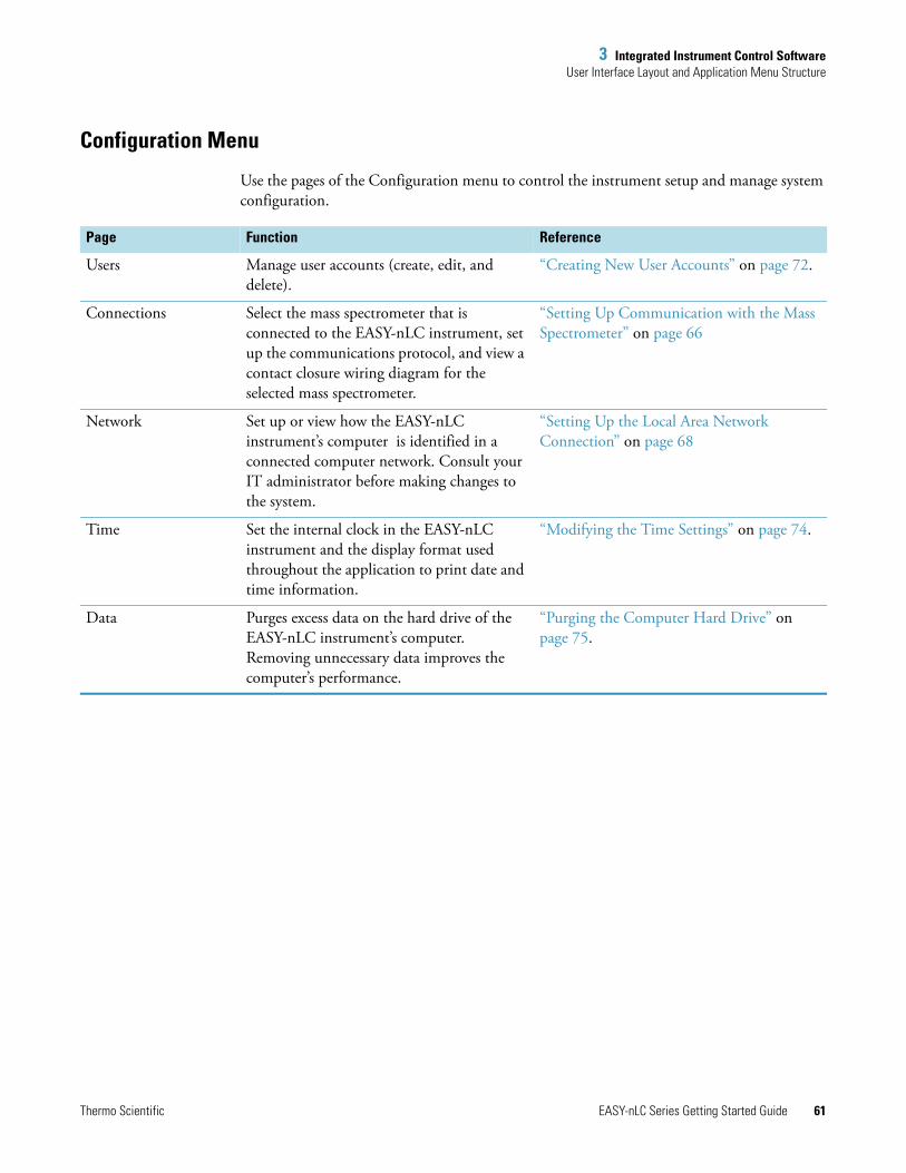
3 Integrated Instrument Control SoftwareUser Interface Layout and Application Menu Structure
Thermo Scientific EASY-nLC Series Getting Started Guide 61
Configuration Menu
Use the pages of the Configuration menu to control the instrument setup and manage system configuration.
Page Function Reference
Users Manage user accounts (create, edit, and delete).
“Creating New User Accounts” on page 72.
Connections Select the mass spectrometer that is connected to the EASY-nLC instrument, set up the communications protocol, and view a contact closure wiring diagram for the selected mass spectrometer.
“Setting Up Communication with the Mass Spectrometer” on page 66
Network Set up or view how the EASY-nLC instrument’s computer is identified in a connected computer network. Consult your IT administrator before making changes to the system.
“Setting Up the Local Area Network Connection” on page 68
Time Set the internal clock in the EASY-nLC instrument and the display format used throughout the application to print date and time information.
“Modifying the Time Settings” on page 74.
Data Purges excess data on the hard drive of the EASY-nLC instrument’s computer. Removing unnecessary data improves the computer’s performance.
“Purging the Computer Hard Drive” on page 75.
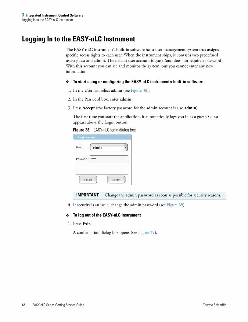
3 Integrated Instrument Control SoftwareLogging In to the EASY-nLC Instrument
62 EASY-nLC Series Getting Started Guide Thermo Scientific
Logging In to the EASY-nLC InstrumentThe EASY-nLC instrument’s built-in software has a user management system that assigns specific access rights to each user. When the instrument ships, it contains two predefined users: guest and admin. The default user account is guest (and does not require a password). With this account you can see and monitor the system, but you cannot enter any new information.
To start using or configuring the EASY-nLC instrument’s built-in software
1. In the User list, select admin (see Figure 38).
2. In the Password box, enter admin.
3. Press Accept (the factory password for the admin account is also admin).
The first time you start the application, it automatically logs you in as a guest. Guest appears above the Login button.
Figure 38. EASY-nLC login dialog box
4. If security is an issue, change the admin password (see Figure 39).
To log out of the EASY-nLC instrument
1. Press Exit.
A confirmation dialog box opens (see Figure 39).
IMPORTANT Change the admin password as soon as possible for security reasons.
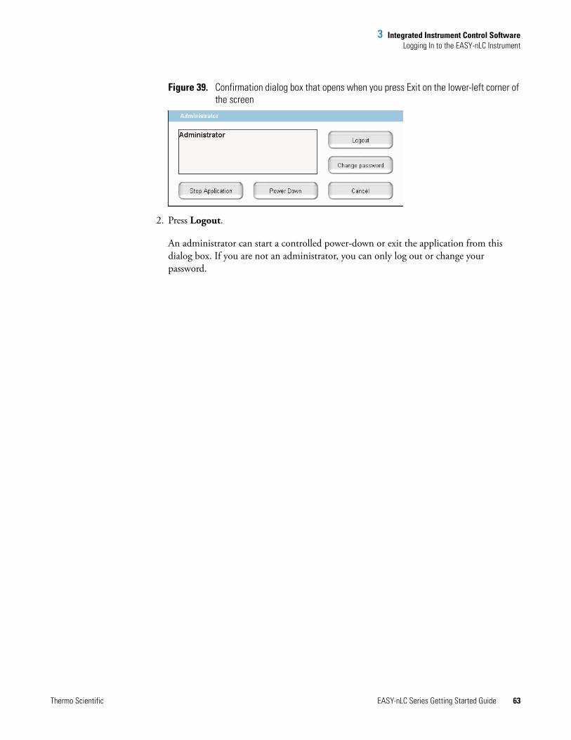
3 Integrated Instrument Control SoftwareLogging In to the EASY-nLC Instrument
Thermo Scientific EASY-nLC Series Getting Started Guide 63
Figure 39. Confirmation dialog box that opens when you press Exit on the lower-left corner of the screen
2. Press Logout.
An administrator can start a controlled power-down or exit the application from this dialog box. If you are not an administrator, you can only log out or change your password.

3 Integrated Instrument Control SoftwareClosing Down the EASY-nLC Instrument
64 EASY-nLC Series Getting Started Guide Thermo Scientific
Closing Down the EASY-nLC InstrumentClosing down the instrument in a controlled manner is important to allow all the components to shut down in an orderly sequence. Using this controlled method saves important data so that the instrument starts with the correct information the next time you use it.
To turn off the EASY-nLC instrument
1. Press Exit (lower-left corner of the screen).
A confirmation dialog box opens (see Figure 39 on page 63).
2. Press Power Down.
The EASY-nLC application displays a white screen with a small progress bar. When the progress bar is filled out and the message appears indicating you can safely turn off the instrument, go to the next step.
3. After receiving the message that you can safely turn off the instrument, turn off the power switch on the back panel of the instrument.
WARNING If you turn off the power switch during normal operation, you risk damaging essential system components. Follow the procedure outlined here whenever possible.

Thermo Scientific EASY-nLC Series Getting Started Guide 65
4
Configuring the EASY-nLC System
After turning on the instrument and logging in as a system administrator, you must configure the instrument’s integrated software application for use and define the network connection for the instrument.
To set up the application configuration, follow the configuration instructions in this chapter.
Contents
• Setting Up Communication with the Mass Spectrometer
• Setting Up the Local Area Network Connection
• Modifying User Permissions
• Modifying the Time Settings
• Purging the Computer Hard Drive
• Setting Up the Properties for the HPLC Device
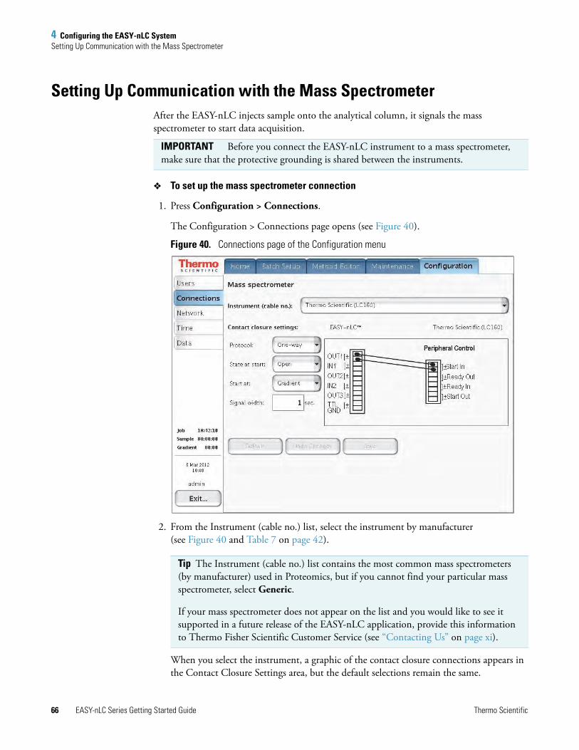
4 Configuring the EASY-nLC SystemSetting Up Communication with the Mass Spectrometer
66 EASY-nLC Series Getting Started Guide Thermo Scientific
Setting Up Communication with the Mass SpectrometerAfter the EASY-nLC injects sample onto the analytical column, it signals the mass spectrometer to start data acquisition.
To set up the mass spectrometer connection
1. Press Configuration > Connections.
The Configuration > Connections page opens (see Figure 40).
Figure 40. Connections page of the Configuration menu
2. From the Instrument (cable no.) list, select the instrument by manufacturer (see Figure 40 and Table 7 on page 42).
When you select the instrument, a graphic of the contact closure connections appears in the Contact Closure Settings area, but the default selections remain the same.
IMPORTANT Before you connect the EASY-nLC instrument to a mass spectrometer, make sure that the protective grounding is shared between the instruments.
Tip The Instrument (cable no.) list contains the most common mass spectrometers (by manufacturer) used in Proteomics, but if you cannot find your particular mass spectrometer, select Generic.
If your mass spectrometer does not appear on the list and you would like to see it supported in a future release of the EASY-nLC application, provide this information to Thermo Fisher Scientific Customer Service (see “Contacting Us” on page xi).

4 Configuring the EASY-nLC SystemSetting Up Communication with the Mass Spectrometer
Thermo Scientific EASY-nLC Series Getting Started Guide 67
3. In the Contact Closure Settings area, do the following:
a. Check the connections on the graphic for the selected mass spectrometer.
b. From the Protocol list select One-way or Two-way synchronization (see Figure 40).
• If the graphic for the selected mass spectrometer (contact closure cable) shows only Start In signals, select One-way synchronization. With a one-way connection, the EASY-nLC instrument sends a start signal to the mass spectrometer.
• If the graphic for the selected mass spectrometer shows two-way communication between the mass spectrometer and the EASY-nLC instrument, select Two-way synchronization. With a two-way connection, the EASY-nLC instrument waits for a ready signal from the mass spectrometer.
c. In the State at Start list, select Open or Closed.
For a Thermo Scientific mass spectrometer, select Open. For other mass spectrometers, refer to the documentation provided with the mass spectrometer or contact Thermo Fisher Scientific Customer Service.
d. In the Start At list, select Gradient or Sample Loading.
• If you want data acquisition to start when the mobile phase gradient starts, select Gradient.
• If you are running the instrument in the one-column mode and you want data acquisition to start when the instrument loads the sample onto the analytical column, select Sample Loading.
e. In the Signal Width box, enter an appropriate signal width.
The default signal width is 1 second. This signal width is sufficient for a Thermo Scientific mass spectrometer. For other mass spectrometers, refer to the documentation provided with the mass spectrometer or contact Thermo Fisher Scientific Customer Service.
Note By setting the Start At value to be the sample loading start, you might be able to acquire data for early-eluting peptides that would not ordinarily bind to the column material and thus be missed from the actual gradient.
Moving the Start At point to the start of the sample loading step can lead to small retention time variations, due to possible differences in pressure buildup before the A/B mixing starts in the actual gradient.

4 Configuring the EASY-nLC SystemSetting Up the Local Area Network Connection
68 EASY-nLC Series Getting Started Guide Thermo Scientific
Setting Up the Local Area Network ConnectionIf you connect the EASY-nLC instrument to the local network (see “Setting Up the Ethernet Connection to a Local Network for Data Exchange” on page 45) and set up the network configuration for the application, you can access the EASY-nLC instrument’s computer from other computers on the network.
To connect the EASY-nLC instrument to a local network
1. Connect the Ethernet cables as described in (see “Setting Up the Ethernet Connection to a Local Network for Data Exchange” on page 45).
2. Press Configuration > Network.
The Network page (Figure 41) contains the configuration address information.
Figure 41. Network page of the Configuration menu
3. In the Profile list, select one of the following:
• To connect to local area network, select MS LAN.
• To connect to the remote support server, select Internet.
IMPORTANT Ask your local IT administrator to help you configure the EASY-nLC instrument on the local network. The following information will help you through the process.

4 Configuring the EASY-nLC SystemSetting Up the Local Area Network Connection
Thermo Scientific EASY-nLC Series Getting Started Guide 69
4. For Configuration, select the Dynamic (addressing DHCP) option or the Fixed (IP address) option.
Your IT administrator knows which option to select.
If IT asks about a MAC address for the instrument—that is, the instrument’s unique network identifier—it is labeled on the connector panel on the back of the instrument. The identifier is a series of numbers and letters and might look like this:
MAC address: 00:E0:4B:07:89:65
External users can now access the file server in the EASY-nLC instrument’s computer to look at log files, for example. Microsoft Windows Explorer might display the file server as shown in Figure 42.
Figure 42. File server access through Windows Explorer
To access the admin folder on the EASY-nLC instrument’s computer hard drive from another computer on the network
1. Type the IP address of the instrument (in the Address list for Windows Explorer), for example, file:\\172.22.50.18, and then press ENTER.
A login dialog box appears.
You need a valid user name and password to enter the file space. The user name and password are the same as those on the EASY-nLC instrument. For example, if you have not changed the default user name and password, the user name is admin and the password is admin.
2. Enter the same user name and password that you use to log in locally to the EASY-nLC instrument.
Type IP address here.

4 Configuring the EASY-nLC SystemModifying User Permissions
70 EASY-nLC Series Getting Started Guide Thermo Scientific
Modifying User PermissionsThe four types of users are Guest (default), Normal, Super User, and Administrator.
Each user type has access to different levels of functionality in the EASY-nLC application.
Having a Guest user account means you can access the top menu but not enter data or issue commands to the instrument.
If a feature is not available, the application grays (blanks) it out, so the user cannot access that function.
Follow these procedures to change passwords and create new user accounts:
• “Changing the Administrator Password” on page 71
• “Creating New User Accounts” on page 72
• “Changing Your Password from the Exit Menu” on page 73
Table 8. User types and permission levels for each menu
Menu User type
Guest Normal Super User Administrator
Home Read onlya
a User has read-only access.
Read/Writeb
b User has read-write access.
Read/Write Read/ Write
Batch Setup Read only Read/Write Read/Write Read/Write
Method Editor Read only Read/Write Read/Write Read/Write
Maintenance N/A N/A Read/Write Read/Write
Configuration N/A N/A N/A Read/Write

4 Configuring the EASY-nLC SystemModifying User Permissions
Thermo Scientific EASY-nLC Series Getting Started Guide 71
Changing the Administrator Password
The EASY-nLC application supplies a simple administrator password. Consider changing it to a more secure password as soon as possible.
To change the administrator password
1. Log in as admin (otherwise, see “Logging In to the EASY-nLC Instrument” on page 62).
2. Press Configuration > Users.
The Configuration > Users page opens (Figure 43).
Figure 43. Users page of the Configuration menu
3. Press Open.
The Select User dialog box opens.
4. In the User list, select Admin.
5. Enter the new password as follows:
a. Press the Password box.
The Enter Password dialog box opens.
b. Type a new password, and then press OK.
c. Press the Re enter box.
The Enter Password dialog box opens.
d. Type the password a second time to confirm it, and then press OK.
6. Press Save to save the user account information.

4 Configuring the EASY-nLC SystemModifying User Permissions
72 EASY-nLC Series Getting Started Guide Thermo Scientific
Creating New User Accounts
Use the Users page to create new user accounts for all the people or groups that will use the instrument. Each user has a private file space for batch jobs and methods that other users (apart from system administrators) cannot see.
In addition, there is a public file space for methods and batch jobs that all users can see and use. Only Super Users and Administrators can copy files into the public spaces and only Administrators can delete files and directories from the public space.
To create a new user account
1. Log in as admin (otherwise, see “Logging In to the EASY-nLC Instrument” on page 62).
2. Press Configuration > Users.
The Configuration > Users page opens (see Figure 43 on page 71).
3. Press New.
The User box changes to the User Login box and becomes available for data input. The Name, Password, and Re enter boxes also become available for data input.
4. Make entries in the User Login and Name boxes.
5. Select the privileges for the user by level: Normal, Super, or Admin. For user privileges by user type, see Table 8 on page 70.
If you want the user to carry out instrument maintenance, you must select Super User as the user type. If you want the user to restore data to the instrument’s computer hard drive, select Admin as the user type.
6. Create an initial password for the defined user by using the Password and Re enter boxes.
Users can change their passwords from the Login/Exit menu.
7. Press Save.

4 Configuring the EASY-nLC SystemModifying User Permissions
Thermo Scientific EASY-nLC Series Getting Started Guide 73
Changing Your Password from the Exit Menu
After logging in, all users can change their password from the Exit menu.
To change your password
1. Press Exit in the lower-right corner of the touch screen.
The Exit dialog box for the current user opens (see Figure 44).
Figure 44. Exit dialog box for the current user
2. Press Change Password.
The Change password for: current user dialog box opens.
3. Make the appropriate entries.
4. Press Accept to accept the new password and close the dialog box.

4 Configuring the EASY-nLC SystemModifying the Time Settings
74 EASY-nLC Series Getting Started Guide Thermo Scientific
Modifying the Time SettingsUse the Configuration > Time page (Figure 45) to set the internal clock in the EASY-nLC instrument and the display format used throughout the application for date and time information.
To set the time zone
1. Press Configuration > Time.
The Configuration > Time page opens (see Figure 45).
Figure 45. Time page of the Configuration menu
2. Select a time zone from the continent/city list.
The Set Time Zone button becomes available.
3. Press Set Time Zone.
To change the display format for the time and date
1. Select a format from the Presets list.
2. Press Set Format.
The time and date format changes immediately on the Maintenance > Log Book page.
Continent/city list
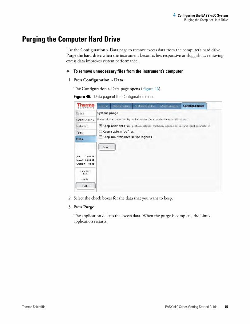
4 Configuring the EASY-nLC SystemPurging the Computer Hard Drive
Thermo Scientific EASY-nLC Series Getting Started Guide 75
Purging the Computer Hard DriveUse the Configuration > Data page to remove excess data from the computer’s hard drive. Purge the hard drive when the instrument becomes less responsive or sluggish, as removing excess data improves system performance.
To remove unnecessary files from the instrument’s computer
1. Press Configuration > Data.
The Configuration > Data page opens (Figure 46).
Figure 46. Data page of the Configuration menu
2. Select the check boxes for the data that you want to keep.
3. Press Purge.
The application deletes the excess data. When the purge is complete, the Linux application restarts.
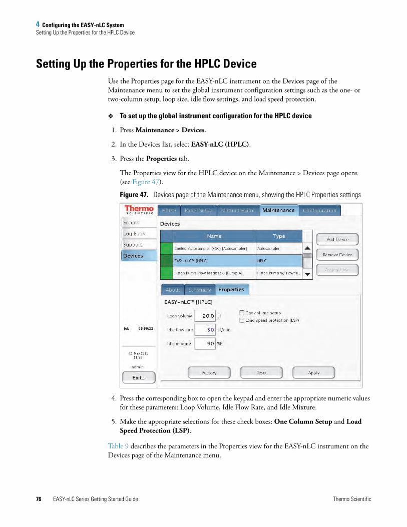
4 Configuring the EASY-nLC SystemSetting Up the Properties for the HPLC Device
76 EASY-nLC Series Getting Started Guide Thermo Scientific
Setting Up the Properties for the HPLC DeviceUse the Properties page for the EASY-nLC instrument on the Devices page of the Maintenance menu to set the global instrument configuration settings such as the one- or two-column setup, loop size, idle flow settings, and load speed protection.
To set up the global instrument configuration for the HPLC device
1. Press Maintenance > Devices.
2. In the Devices list, select EASY-nLC (HPLC).
3. Press the Properties tab.
The Properties view for the HPLC device on the Maintenance > Devices page opens (see Figure 47).
Figure 47. Devices page of the Maintenance menu, showing the HPLC Properties settings
4. Press the corresponding box to open the keypad and enter the appropriate numeric values for these parameters: Loop Volume, Idle Flow Rate, and Idle Mixture.
5. Make the appropriate selections for these check boxes: One Column Setup and Load Speed Protection (LSP).
Table 9 describes the parameters in the Properties view for the EASY-nLC instrument on the Devices page of the Maintenance menu.

4 Configuring the EASY-nLC SystemSetting Up the Properties for the HPLC Device
Thermo Scientific EASY-nLC Series Getting Started Guide 77
Table 9. HPLC parameter descriptions
Parameter Description
Loop Volume Specifies the nominal size of the installed sample loop.
Take care to specify the correct loop size. If you specify a smaller loop size than the installed loop size, the instrument might draw sample into the sample pump.
Idle Flow Rate Specifies the solvent flow rate when the instrument is idle. This feature activates when the last sample in a batch is done.
If you do not want a solvent flow through the instrument when it is idle, type 0 in the Idle Flow Rate box.
Maintaining long-term emitter stability (with glass emitters) might require constant flow through the system.
One Column Setup Specifies the one-column setup.
The diagram on the Overview page of the Home menu displays the column setup.
Load Speed Protection When this check box is selected, the instrument uses the flow rate entered in Sample Loading area on page 2/5 of the Method Editor wizard (see “Setting Up the Sample Pickup and Loading Steps” on page 110) to load the sample onto the precolumn (or the analytical column for a one-column setup). During a batch run, the sequence stops immediately if the system reaches the maximum pressure limit entered in the Sample Loading area.
The LSP feature ensures that the solvent delivery system loads each sample onto the column at the same flow rate. Because the flow rate used to load the sample onto the column can affect sample-to-sample reproducibility for quantitation experiments, use the LSP feature to maximize sample-to-sample reproducibility for quantitation experiments.
LSP is only active during the sample loading step of a run.
To use the LSP feature correctly, you must enter both a flow and a maximum pressure limit for sample loading in the method file. To determine an appropriate flow rate for your LC columns, use the precolumn and analytical column equilibration scripts.


Thermo Scientific EASY-nLC Series Getting Started Guide 79
5
Preparing the EASY-nLC Instrument for Use
To prepare the EASY-nLC instrument for use, log in to the instrument with either Super User or Administrator privileges (see “Logging In to the EASY-nLC Instrument” on page 62), and then follow these procedures.
Daily and Weekly Maintenance TasksFor optimal system performance, check the solvent levels, draw fresh solvent through the solvent system, and flush air out of the system on a daily basis.
Because the vapor pressures of formic acid, water, and acetonitrile differ, the solvent composition changes over time. Refill the solvent bottles to maintain a consistent solvent composition on a weekly basis.
To check the solvent levels
1. Visually inspect solvent bottle A, solvent bottle B, and the autosampler bottle in position W3 (and the bottles in position W1 and W2 if used). Refill if necessary.
2. Visually inspect the autosampler wash bottle in position W4 and the waste container in the pump compartment, and empty if necessary.
Contents
• Daily and Weekly Maintenance Tasks
• Preparing Solvent Bottles and Waste Containers
• Executing Maintenance Scripts
• Purging and Flushing the Pumps
• Setting Up the Column Assembly
• Using nanoViper Fittings
• Equilibrating Columns
Tip You can also inspect the purity of the solvent to ensure no visible precipitates have formed that might lead to blockages in the pump line.

5 Preparing the EASY-nLC Instrument for UsePreparing Solvent Bottles and Waste Containers
80 EASY-nLC Series Getting Started Guide Thermo Scientific
To draw fresh solvent into the system and to flush air out of the system
Run the Purge Solvent and Flush Air scripts with two purge iterations or until flush volumes fall below 10 μL for the EASY-nLC II instrument or 12 μL for the EASY-nLC 1000 instrument.
For more information, see “Purging and Flushing the Pumps” on page 86.
Preparing Solvent Bottles and Waste ContainersAs you prepare the solvent bottles and empty the waste containers, you work with hazardous solvents and chemicals such as methanol, acetonitrile, formic acid, and so on. Before working with hazardous solvents and chemicals, review the specific hazards for each substance by reading the MSDSs provided by the manufacturer. When working with solvents and chemicals, wear the appropriate safety gear.
Before shipment, the EASY-nLC instrument’s solvent system is flushed with methanol.
To set up the two bottles that contain the mobile phase solvents, the four autosampler bottles, and the waste beaker, follow these topics:
• “Solvent Requirements” on page 81
• “Solvent A and B Bottles” on page 82
• “Autosampler Wash Bottles and Waste Beaker” on page 83
CAUTION When working with solvents, wear safety glasses and safety gloves. Make sure that the gloves are compatible with the solvents you are using.
CAUTION Methanol (CAS number: 67-56-1) is highly flammable and toxic by inhalation, ingestion, or skin absorption. Take appropriate measures to protect yourself and your equipment. Make sure that the mobile phases are miscible with methanol or flush the A and B solvent lines with an intermediate solvent.

5 Preparing the EASY-nLC Instrument for UsePreparing Solvent Bottles and Waste Containers
Thermo Scientific EASY-nLC Series Getting Started Guide 81
Solvent Requirements
The installation solvents for the EASY-nLC 1000 instrument are as follows:
To prepare these solutions, order the appropriate LC/MS-grade solvents or the pre-blended solutions. Table 10 lists the solvents that you can order from Thermo Fisher Scientific.
To order LC/MS-grade solvents from Thermo Fisher Scientific
Click this icon, .
–or –
Go to: www.FisherLCMS.com, and click the Solvents tab.
Solvent A: 0.1% formic acid in waterSolvent B: 0.1% formic acid in acetonitrileWash solvent 3: 0.1% formic acid in water
Table 10. Solvents
Solvent/reagent Specification
Water LC/MS grade
Acetonitrile LC/MS grade
Formic acid (99.5%) LC/MS grade
0.1% formic acid in water LC/MS grade
0.1% formic acid in acetonitrile LC/MS grade
IMPORTANT Use only LC/MS-grade solvent. Do not filter solvents. Filtering solvents can introduce contamination.
CAUTION Store and handle all chemicals in accordance with standard safety procedures.

5 Preparing the EASY-nLC Instrument for UsePreparing Solvent Bottles and Waste Containers
82 EASY-nLC Series Getting Started Guide Thermo Scientific
Solvent A and B Bottles
Follow these recommended steps to prepare the two solvent bottles.
To prepare the solvent A and B bottles
1. Fill the 25 ml Schott Duran™ blue cap bottles with the mobile phase solvents.
2. Degas the solvents by sonicating the solvent bottles in a sonication bath or by sparging the solvents with helium gas.
3. Place the bottles in the holder on top of the instrument: solvent A bottle in the front and solvent B bottle in the back position.
4. Mount the inline filter assembly on the blue cap lids as shown in Figure 48 and Figure 49.
Figure 48. Inline filter assembly (exploded view)
Figure 49. Assembled inline filter
IMPORTANT To establish proper surface wetting, prime the filters with methanol or acetonitrile.

5 Preparing the EASY-nLC Instrument for UsePreparing Solvent Bottles and Waste Containers
Thermo Scientific EASY-nLC Series Getting Started Guide 83
Autosampler Wash Bottles and Waste Beaker
The autosampler compartment holds the sample trays, up to four wash bottles, and a waste beaker (see Figure 50). You can operate the instrument after installing the wash bottle that the autosampler uses for needle cleaning (position W4), the wash bottle that contains solvent A for pump S (position W3), and the waste beaker that collects the waste from pumps A and B and from the venting Tee through valve W.
To access the autosampler compartment, you can manually open the tray compartment door or you can press the Eject Plate button on the Home > Overview page.
Figure 50. Autosampler compartment
To install the waste beaker and prepare and install the wash bottles
1. Fill one of the wash bottles with solvent A and degas it.
2. Turn on the instrument and make sure that the area in front of the tray compartment door is free from obstruction.
3. Press Home > Overview. Then press Eject Plate.
A confirmation dialog box appears to remind you to remove obstacles from the area in front of the tray compartment before commanding the instrument to open the tray compartment door.
Waste beaker
Wash bottles (W3 and W4)
Vial tray

5 Preparing the EASY-nLC Instrument for UsePreparing Solvent Bottles and Waste Containers
84 EASY-nLC Series Getting Started Guide Thermo Scientific
4. Press Accept.
The tray compartment door opens.
5. Put the bottle with the needle wash insert into position W4 (see Figure 51).
Figure 51. Wash bottle with needle wash insert and view of the four positions on the autosampler bottle holder
6. Put a wash bottle that contains solvent A into position W3.
Pump S draws solvent from this position. You can place wash solvents for customized washing procedures in positions W1 and W2.
7. Make sure all the bottles are installed with the lids fitting tightly.
8. Place the waste container (a 250 mL plastic beaker) into the compartment on the right side of the autosampler compartment.
9. Press Insert Plate to move the plate back into the instrument.
CAUTION You must place the wash bottle with the needle wash insert in position W4. Any other position could lead to instrument malfunction and possible breakdown.
W1 W2 W3 W4
Wash bottle with needle wash insert
Autosampler bottle holder

5 Preparing the EASY-nLC Instrument for UseExecuting Maintenance Scripts
Thermo Scientific EASY-nLC Series Getting Started Guide 85
Executing Maintenance ScriptsThe EASY-nLC application has a set of maintenance scripts that you can access from the Scripts page (Figure 52) of the Maintenance menu.
You use the scripts in the Prepare category for common tasks such as drawing fresh solvent through the solvent system, flushing air out of the system, and equilibrating the columns.
Before you start any of the maintenance scripts, prepare the instrument as described in “Preparing Solvent Bottles and Waste Containers” on page 80.
Figure 52. Scripts page of the Maintenance menu
The green START button is active when a job or script is ready to execute. After you press START, the STOP button replaces the START button and remains active until the job or script ends. During execution you can terminate a job or script by pressing the red STOP button.
When the Schedule button is available, you can automate the start of the Flow Sensor calibration script and all of the scripts in the Prepare category. You cannot schedule the remaining scripts because they require supervision or hardware changes to the instrument.
Note You cannot execute maintenance scripts when the EASY-nLC instrument is running batches.

5 Preparing the EASY-nLC Instrument for UsePurging and Flushing the Pumps
86 EASY-nLC Series Getting Started Guide Thermo Scientific
Purging and Flushing the PumpsBecause the EASY-nLC pumps are purged with methanol before delivery, thoroughly purge the pumps with the mobile phase solvents before doing any analytical runs. In addition, purge the pumps when switching to a new solvent.
The purge pump job fills the selected pump or pumps with solvent and then ejects the solvent into the waste container. You can specify how many iterations of this job you want performed.
After purging the pumps, flush them to remove any air that might be trapped inside. You can specify the maximum number of iterations for this job, the period of time that the pumps are being pressurized, and the success criteria for stopping the operation earlier than scheduled.
To purge and flush pumps A and B
1. Before you purge the pumps with fresh solvent, make sure that the solvent bottles A and B on the top of the instrument are filled with solvent.
2. Press Maintenance > Scripts.
The Scripts page of the Maintenance menu opens.
3. Set up the purge solvents job as follows (see Figure 53):
a. In the Category list, select Prepare.
b. In the Name list, select Purge Solvent.
c. Press the Parameters tab.
d. In the Purge Iterations box, enter 10.
This is the number of times that the pumps will completely refill and eject the solvent.
e. Select the Purge Pump A, Purge Pump B, and Purge Pump S check boxes.
Tip To enter the number of purge iterations, press the empty cell in the Value column. The Set Value dialog box appears. Use the numeric keypad to type the number of purge iterations that you want. Then press Accept. The new value appears in the Value column.
Note The pumps draw and eject solvent as follows:
• Pump S draws solvent from bottle W3 in the autosampler bottle holder and ejects solvent into bottle W4.
• Pump A and pump B draw solvent from the solvent A and B bottles on top of the instrument and eject solvent to the waste cup.

5 Preparing the EASY-nLC Instrument for UsePurging and Flushing the Pumps
Thermo Scientific EASY-nLC Series Getting Started Guide 87
Figure 53. Purge solvent job parameters
4. To save these settings and continue, press Schedule.
The Queue page of the Home menu appears.
5. Set up the flush air job as follows (see Figure 54):
a. Press Maintenance > Scripts.
b. In the Category list, select Prepare.
c. In the Name list, select Flush Air.
d. Press the Parameters tab.
e. In the Flush Vol. Threshold [μL] box, enter the appropriate flush volume.
This values helps to ensure an acceptable amount of solvent compressibility.
f. Select the Flush Pump A, Flush Pump B, and Flush Pump S check boxes.
System Flush volume
EASY-nLC II 10 μL
EASY-nLC 1000 12 μL
Tip To enter the flush volume, press the empty cell in the Value column. The Set Value dialog box appears. Use the numeric keypad to type the volume that you want. Then press Accept. The new value appears in the Value column.
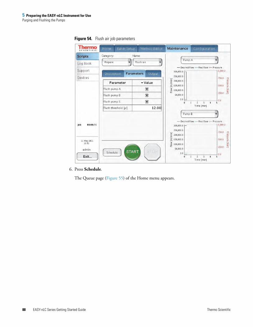
5 Preparing the EASY-nLC Instrument for UsePurging and Flushing the Pumps
88 EASY-nLC Series Getting Started Guide Thermo Scientific
Figure 54. Flush air job parameters
6. Press Schedule.
The Queue page (Figure 55) of the Home menu appears.

5 Preparing the EASY-nLC Instrument for UsePurging and Flushing the Pumps
Thermo Scientific EASY-nLC Series Getting Started Guide 89
Figure 55. Queue page of the Home menu, showing the queued jobs
7. In the Jobs list, make sure the check box in the Auto-Continue column is selected for Flush Air.
8. Press Overview.
The Overview page of the Home menu opens.
9. Press START.
The default selections appear in the two graph windows on the Scripts page of the Maintenance menu, but you can change the selection for a window from its corresponding list. These graphs help you to monitor the job.
10. Wait for the jobs to end (the flush air job continues until the flush air volume values are below the specified threshold).
Note While a maintenance job or a script is running, you cannot start other jobs or scripts.

5 Preparing the EASY-nLC Instrument for UseSetting Up the Column Assembly
90 EASY-nLC Series Getting Started Guide Thermo Scientific
Setting Up the Column AssemblyTo integrate the EASY-nLC instrument with a Thermo Scientific mass spectrometer, Thermo Fisher Scientific provides two nanospray ion sources: the NanoFlex source and the EASY-Spray source.
The columns used with these two sources differ. With the NanoFlex source, use standard nanoflow columns for both the one- or two-column setup. With the EASY-Spray source, use an EASY-Spray column as the analytical column in both the one- or two-column setup. To create a two-column setup for the EASY-Spray source, use a standard nanoflow column with nanoViper fittings as the precolumn.
To set up the column assembly for your nanospray source, follow the appropriate procedure:
• “Setting Up the Column Assembly for the NanoFlex Source,” on this page
• “Setting Up the Column Assembly for the EASY-Spray Source” on page 95
Setting Up the Column Assembly for the NanoFlex Source
If your LC/MS system has a NanoFlex ion source, follow the appropriate procedure for your EASY-nLC instrument to connect either a one- or two-column assembly.
• “Setting Up the Column Assembly for an EASY-nLC II Instrument and a NanoFlex Source,” on this page
• “Setting Up the Column Assembly for an EASY-nLC 1000 Instrument and a NanoFlex Source” on page 92
Setting Up the Column Assembly for an EASY-nLC II Instrument and a NanoFlex Source
The EASY-nLC II instrument comes with the following column assembly components:
• Precolumn (EASY-Column™, 2 cm length, 100 μm ID, 5 μm particle size, C18-A1)
• Analytical column (EASY-column, 10 cm length, 75 μm ID, 3 μm particle size, C18-A2)
• Unions and fittings for connecting 375 μm OD and 1/32 in. OD columns
You can use other types of column ODs. Contact Thermo Fisher Scientific for help with choosing the appropriate fittings.
CAUTION Wear protective gloves and safety glasses when handling the solvent lines. To prevent contamination, use lint-free and powder-free gloves.

5 Preparing the EASY-nLC Instrument for UseSetting Up the Column Assembly
Thermo Scientific EASY-nLC Series Getting Started Guide 91
To connect the EASY-column assembly for the NanoFlex source to the Column Out and Waste In solvent lines of an EASY-nLC II instrument
1. Connect the red ZDV union (P/N SC600) to the Column Out line.
For instructions about connecting the union, read the instructions provided with the union.
2. Connect the precolumn to the other end of the red union. Use the provided sleeves (P/N SC603) if the precolumn is a 375 μm OD column.
3. Connect the outlet end of the precolumn to the venting Tee (P/N SC601). Again, use the provided sleeve (P/N SC603) if the precolumn is a 375 μm OD column.
4. Connect the angled end of the venting Tee to the Waste-In PEEKsil line.
5. Connect the straight end of the venting Tee to the analytical column. Use the provided sleeve (SC603) if the analytical column is a 375 μm OD column.
6. Connect the analytical column outlet to the transfer line going to the detector.
Figure 56. EASY-nLC II column setup (375 μm OD columns)
Tip Two 1/32 in. OD PEEKsil™ lines exit from the slot in the right side panel of the instrument.
For the initial instrument configuration, these solvent lines are labeled Column Out and Waste In. If your instrument has been modified, the solvent lines might not be labeled.
To identify the two solvent lines, remove the instrument’s right side panel and check the solvent line connections. The sample transfer line (Column Out) connects to valve S and the waste line (Waste In) connects to valve W.
Waste-In line
Precolumn Venting Tee Analytical columnColumn-Out line
Zero dead volume (ZDV)union

5 Preparing the EASY-nLC Instrument for UseSetting Up the Column Assembly
92 EASY-nLC Series Getting Started Guide Thermo Scientific
Setting Up the Column Assembly for an EASY-nLC 1000 Instrument and a NanoFlex Source
Table 11 lists the columns, fittings, and unions that make up the two-column assembly that ships with the EASY-nLC 1000 instrument.
Make sure that you connect the venting Tee to the Waste In line for both the one-column and two-column setups.
To connect the column assembly for the NanoFlex source to the EASY-nLC 1000 instrument
1. Do one of the following:
• For a two-column setup, go to step 2.
• For a one-column setup, go to step 3.
2. For a two-column setup, connect the Column Out line to the stainless steel union as follows:
a. Slightly loosen the nanoViper fitting connected to the stainless steel union.
b. Insert the nanoViper fitting on the Column Out line into the other end of the stainless steel union, and then slowly tighten the fitting until you feel resistance.
c. Tighten both fittings by an additional 45 degrees (1/8-turn). Do not tighten the fittings by more than a 1/4-turn (see “Using nanoViper Fittings” on page 102).
Table 11. Columns and column fittings
Item Description Part number
Precolumn (trap column) with nanoViper fittings
Acclaim™ PepMap 100, 2 cm length, 75 μm ID, 3 μm particle size, C18 column packing
Thermo Scientific Dionex™ 164705
Analytical column with nanoViper fittings
Acclaim PepMap RSLC, 15 cm length, 50 μm ID, 2 μm particle size, C18 column packing
Thermo Scientific Dionex 164704
PEEK union with fittings 0.76 in. length, 0.035 in. thru-port, for 1/32 in. OD tubing
Stainless steel union, ZDV For 1/16 in. OD tubing SC900
Venting Tee Stainless steel, 0.15 mm bore, for 1/16 in. OD tubing
SC901
PEEK sleeves for 280 μm fused-silica
330 μm ID, 1/32 in. OD SC903
CAUTION Because the fittings seal against each other inside the union, do not tighten them by more than 90 degrees (1/4-turn). Overtightening the fittings can irreparably damage their sealing surfaces.

5 Preparing the EASY-nLC Instrument for UseSetting Up the Column Assembly
Thermo Scientific EASY-nLC Series Getting Started Guide 93
d. Go to step 4.
3. For a one-column setup, if you are working with the column assembly shipped with the instrument, remove the precolumn from the column assembly. Connect the Column Out line directly to the venting Tee.
4. Connect the Waste In line to the venting Tee as follows:
a. Remove the plug from the third port of the venting Tee.
b. Insert the nanoViper fitting at the end of the Waste In line into the free port of the Tee (see Figure 57 and Figure 58). Slowly tighten the fitting until you feel resistance. Then tighten the fitting by an additional 1/8- to 1/4-turn. Do not tighten the fitting by more than a 1/4-turn (see “Using nanoViper Fittings” on page 102).
Figure 57 shows the one-column setup and Figure 58 shows the two-column setup. Both setups use the venting Tee.
Figure 57. One-column assembly connected to the EASY-nLC instrument’s Column Out and Waste In tubing
Figure 58. Two-column assembly connected to the EASY-nLC instrument’s Column Out and Waste In tubing
Flow
VICI
PEEK union
Analytical column15 cm length
PEEK sleeve
Column Out tubing
Waste Intubing
Venting Tee
FlowFlow
VICI
Stainless steel union PEEK union
Analytical column15 cm length
PEEK sleeve
Column Out tubing
Waste Intubing
Venting Tee
Precolumn2 cm length

5 Preparing the EASY-nLC Instrument for UseSetting Up the Column Assembly
94 EASY-nLC Series Getting Started Guide Thermo Scientific
Connecting an Emitter to the Analytical Column
Before you mount the column assembly onto the ion source, connect an emitter to the analytical column.
To connect an emitter to the PEEK union
1. If you are using the preassembled column assembly, disconnect the analytical column from the PEEK union.
2. Connect the white distance-gauge plug to one end of the PEEK union.
3. Using a sleeve, connect the emitter to the other end of the PEEK union as follows:
a. Thread the blunt end of the emitter through the adapter sleeve. Ensure that the blunt end of the emitter does not protrude from the sleeve by more than 1 mm (see Figure 59).
Figure 59. Sleeved emitter
b. To ensure proper seating, slide the blunt end of the sleeved emitter through the PEEK nut until it protrudes slightly (approximately 1 to 2 mm) from the front of the fitting.
c. As you gently press the sleeved emitter against the union port, screw the nut into the port until fingertight. Be careful not to overtighten the fitting.
4. Remove gauge from the PEEK union and reconnect the analytical column.
CAUTION Because the emitter tip is sharp enough to puncture skin and easily damaged, do not touch it.
Blunt end of the emitter
Emitter tip
Adapter sleeve

5 Preparing the EASY-nLC Instrument for UseSetting Up the Column Assembly
Thermo Scientific EASY-nLC Series Getting Started Guide 95
Setting Up the Column Assembly for the EASY-Spray Source
If your LC/MS has an EASY-Spray source, follow the appropriate procedure to connect either a one- or two-column setup.
• “Connecting an EASY-Spray Column to an EASY-nLC II Instrument” on page 96
• “Connecting an EASY-Spray Column to an EASY-nLC 1000 Instrument” on page 99
The EASY-Spray Ion Source Kit contains the fittings and sleeves for the plumbing connections (see Table 12).
Table 12. Fittings and sleeves in the EASY-Spray Ion Source Kit
Image Description Part number
A/B mixing/venting Tee, stainless steel, with three attached ferrules and nuts
SC901
Sleeves, PEEK™, 1/16 in. OD IDEX™, F-233
Viper™ union (for the EASY-nLC 1000 instrument)
Thermo Scientific Dionex, 6040.2304
ZDV adapter union (1/16 to 1/32 in.) and plug (not shown)(for the EASY-nLC II instrument)
IDEX, P-881
CAUTION Wear protective gloves and safety glasses when handling the solvent lines. To prevent contamination, use lint-free and powder-free gloves.

5 Preparing the EASY-nLC Instrument for UseSetting Up the Column Assembly
96 EASY-nLC Series Getting Started Guide Thermo Scientific
Connecting an EASY-Spray Column to an EASY-nLC II Instrument
Follow the appropriate procedure for a one- or two-column setup. The two-column setup includes a precolumn connected in the column-out flow path to the venting Tee.
• “To connect a one-column setup for an EASY-nLC II instrument and an EASY-Spray source,” on this page
• “To connect a two-column setup for an EASY-nLC II instrument and an EASY-Spray source” on page 97
To connect a one-column setup for an EASY-nLC II instrument and an EASY-Spray source
1. Using the fittings connected to the venting Tee and the sleeves in the EASY-Spray Ion Source Kit, connect the Column Out and Waste In lines to the venting Tee as follows:
a. For each solvent line, do the following:
i. Slide a sleeve onto the end of the solvent line until the sleeve is flush with the end of the solvent line.
ii. Slide the nut and then the ferrule onto the sleeved line until the sleeve extends past the ferrule (see Figure 60).
Figure 60. Solvent line with sleeve, ferrule, and nut
b. Insert the end of the Column Out line into one of the venting Tee’s parallel ports. Tighten the nut by hand until you feel resistance, and then use the 1/4 in. wrench to tighten the nut until firmly secured—do not overtighten.
c. Insert the end of the Waste In line into the venting Tee’s perpendicular port. Tighten the nut by hand until you feel resistance, and then use the 1/4 in. wrench to tighten the nut until firmly secured—do not overtighten.
2. Insert the nanoViper fitting at the inlet end of the EASY-Spray column into the venting Tee’s free parallel port. Slowly tighten the fitting until you feel resistance. Then tighten the fitting by an additional 1/8- to 1/4-turn. Do not tighten the fitting by more than a 1/4-turn (see “Using nanoViper Fittings” on page 102).
Note The venting Tee has three ports. Use the two parallel ports to connect the sample transfer line. Use the perpendicular port to connect the waste line.
Nut Ferrule
Sleeve

5 Preparing the EASY-nLC Instrument for UseSetting Up the Column Assembly
Thermo Scientific EASY-nLC Series Getting Started Guide 97
Figure 61 shows an example of a one-column setup for an EASY-nLC II instrument and an EASY-Spray source.
Figure 61. EASY-Spray column (one-column setup) connected to an EASY-nLC II instrument
To connect a two-column setup for an EASY-nLC II instrument and an EASY-Spray source
1. Remove the fittings from the ZDV adapter union supplied in the EASY-Spray Ion Source Kit.
A one-piece fitting for 1/32 in. OD tubing connects to the narrow end and a one-piece fitting for 1/16 in. OD tubing connects to the wide end of the ZDV adapter union. The adapter union is also supplied with a plug that connects to the wide end.
Figure 62. ZDV adapter union and fittings
Tip When you install the one-column assembly, make sure that the One Column Setup check box in the EASY-nLC device section on the Devices page of the Maintenance menu is selected (see “Setting Up the Properties for the HPLC Device” on page 76).
Column Out line
Waste In line
EASY-Spray column
Venting Tee
Fitting for 1/32 in. OD tubingIDEX P/N F-126S
Fitting for 1/16 in. OD tubing(IDEX P/N F-120)
ZDV adapter union(IDEX P/N P-881)

5 Preparing the EASY-nLC Instrument for UseSetting Up the Column Assembly
98 EASY-nLC Series Getting Started Guide Thermo Scientific
2. Using the ZDV adapter union and the one-piece fitting for 1/32 in. OD tubing, connect the Column Out line to a precolumn as follows:
a. Carefully slide the one-piece fitting for 1/32 in. OD tubing onto the end of the Column Out line until the solvent line extends past the fitting (Figure 63).
Figure 63. Column Out line with fitting
b. Connect the plug to the wide end of the ZDV adapter union.
c. Insert the Column Out line into the narrow end of the union, and then tighten the fitting until you feel resistance.
d. Remove the plug from the adapter union.
e. Insert the nanoViper fitting at the inlet end of the precolumn into the wide end of the adapter union. Slowly tighten the fitting until you feel resistance. Then tighten the fitting by an additional 1/8- to 1/4-turn. Do not tighten the fitting by more than a 1/4-turn (see “Using nanoViper Fittings” on page 102).
3. Connect the nanoViper fitting at the outlet end of the precolumn into a parallel port on the venting Tee. Carefully tighten the fitting as described in “Using nanoViper Fittings” on page 102.
4. Connect the Waste In line to the perpendicular port of the venting Tee as follows:
a. Slide a sleeve onto the end of the solvent line until the sleeve is flush with the end of the solvent line.
b. Slide the nut and then the ferrule onto the sleeved line until the sleeve extends past the ferrule (see Figure 60 on page 96).
c. Insert the tubing and fitting into the venting Tee’s perpendicular port. Tighten the nut by hand until you feel resistance, and then use the 1/4 in. wrench to tighten the nut until firmly secured—do not overtighten.
5. Insert the nanoViper fitting at the inlet end of the EASY-Spray column into the venting Tee’s free parallel port. Slowly tighten the fitting until you feel resistance. Then tighten the fitting by an additional 1/8- to 1/4-turn. Do not tighten the fitting by more than a 1/4-turn (see “Using nanoViper Fittings” on page 102).
Figure 64 shows a two-column setup for an EASY-nLC II instrument with an EASY-Spray source.
Note Follow the recommended flow direction stated on the precolumn label.
Fitting for 1/32 in. OD tubing

5 Preparing the EASY-nLC Instrument for UseSetting Up the Column Assembly
Thermo Scientific EASY-nLC Series Getting Started Guide 99
Figure 64. Two-column setup an the EASY-nLC II instrument and an EASY-Spray source
Connecting an EASY-Spray Column to an EASY-nLC 1000 Instrument
Follow the appropriate procedure for a one- or two-column setup. The two-column setup includes a precolumn in the column-out flow path to the venting Tee.
• “To connect an EASY-Spray column for a one-column setup to the EASY-nLC 1000 instrument” on page 100
• “To connect a two-column setup with a precolumn and an EASY-Spray column to an EASY-nLC 1000 instrument” on page 101
Tip When you install the two-column assembly, clear the One Column Setup check box in the EASY-nLC device section on the Devices page of the Maintenance menu (see “Setting Up the Properties for the HPLC Device” on page 76).
Flow
Column Out line
Waste In line
EASY-Spray column

5 Preparing the EASY-nLC Instrument for UseSetting Up the Column Assembly
100 EASY-nLC Series Getting Started Guide Thermo Scientific
To connect an EASY-Spray column for a one-column setup to the EASY-nLC 1000 instrument
1. Remove the fittings from the venting Tee (P/N SC901) supplied in the EASY-Spray Ion Source Kit.
These fittings are not used with the EASY-nLC 1000 instrument.
2. Connect the nanoViper fittings at the ends of the Column Out and Waste In solvent lines and the nanoViper fitting at the inlet end of the EASY-Spray column to the venting Tee as follows:
• Insert the nanoViper fitting at the end of the Column Out solvent line into one of the venting Tee’s parallel ports. Slowly tighten the fitting until you feel resistance. Then tighten the fitting by an additional 1/8- to 1/4-turn. Do not tighten the fitting by more than a 1/4-turn (see “Using nanoViper Fittings” on page 102).
• Insert the nanoViper fitting at the end of the Waste In solvent line into the venting Tee’s perpendicular port, and then carefully tighten the fitting.
• Insert the nanoViper fitting at the inlet end of the EASY-Spray column into the venting Tee’s free parallel port, and then carefully tighten the fitting.
Figure 65 shows the one-column setup for an EASY-Spray column and an EASY-nLC 1000 instrument.
Figure 65. One-column setup with an EASY-Spray column and an EASY-nLC 1000 instruments
Note The venting Tee has three ports. Use the two parallel ports to connect the sample transfer line. Use the perpendicular port to connect the waste line.
Tip When you install the one-column assembly, make sure that the One Column Setup check box in the EASY-nLC device section on the Devices page of the Maintenance menu is selected (see “Setting Up the Properties for the HPLC Device” on page 76).
Column Out line
Waste In line
EASY-Spray column
Venting Tee

5 Preparing the EASY-nLC Instrument for UseSetting Up the Column Assembly
Thermo Scientific EASY-nLC Series Getting Started Guide 101
To connect a two-column setup with a precolumn and an EASY-Spray column to an EASY-nLC 1000 instrument
1. Using a Viper union, connect the Column Out line and the precolumn inlet as follows:
• Insert the nanoViper fitting at the end of the Column Out line into the Viper union. Slowly tighten the fitting until you feel resistance. Then tighten the fitting by an additional 1/8- to 1/4-turn. Do not tighten the fitting by more than a 1/4-turn (see “Using nanoViper Fittings” on page 102).
• Insert the nanoViper fitting at the inlet end of the precolumn into the other end of the Viper union, and then carefully tighten the fitting.
2. Connect the outlet end of the precolumn, the inlet end of the EASY-Spray column, and the Waste In line to the venting Tee as follows:
• Insert the nanoViper fitting on the outlet end of the precolumn into one of the venting Tee’s parallel ports, and then carefully tighten the fitting.
• Connect nanoViper fitting on the inlet end of the EASY-Spray column to the venting Tee’s free parallel port, and then carefully tighten the fitting.
• Insert the fitting on the end of the Waste In line into the venting Tee’s perpendicular port. and then carefully tighten the fitting.
Figure 66 shows a two-column setup for an EASY-nLC 1000 instrument and an EASY-Spray source.
Figure 66. Two-column setup for an EASY-nLC 1000 instrument and an EASY-Spray source
Note Follow the recommended flow direction stated on the precolumn label.
Note The venting Tee has three ports. Use the two parallel ports to connect the sample transfer line. Use the perpendicular port to connect the waste line.
Tip When you install the two-column assembly, clear the One Column Setup check box in the EASY-nLC device section on the Devices page of the Maintenance menu (see “Setting Up the Properties for the HPLC Device” on page 76).
Flow
Column Out line
Waste In line
EASY-Spray column

5 Preparing the EASY-nLC Instrument for UseUsing nanoViper Fittings
102 EASY-nLC Series Getting Started Guide Thermo Scientific
Using nanoViper FittingsFor the EASY-nLC 1000 instrument, most of the plumbing connections are made with nanoViper fittings (see Figure 67).
Figure 67. nanoViper fitting
Even though nanoViper fittings can withstand UHPLC back pressures of up to ~1034 bar (~15 000 psi), they are fingertight fittings, which require only very small torques to seal. Therefore, it is essential to follow the guidelines below to avoid damage by overtightening.
To connect a nanoViper fitting to a receiving port
1. Insert the nanoViper fitting into the target port and slowly rotate the screw clockwise until you feel resistance.
2. Using the black, knurled tightening tool, turn the screw clockwise to an angle between 0 and 45 degrees (1/8-turn).
3. Run the Leaks script for the system as described in the EASY-nLC Series Troubleshooting and Maintenance Guide.
When the leak test ends, the system is at atmospheric pressure.
4. If the Leaks script fails because the new connection is not leak tight, use the black knurled nut to turn the screw up to an additional 45 degrees. Do not turn the screw beyond an angle of 90 degrees from where you felt the initial resistance.
IMPORTANT To prevent damage to the sealing surface of the nanoViper fitting, take care not to overtighten the nanoViper fitting.
IMPORTANT To extend the lifetime of the nanoViper fittings, open and close connections at atmospheric system pressures only. Opening and closing connections at high system pressures can reduce the lifetime of the fitting system.
PEEK sealing surface
Screw Removable, black,knurled tightening tool

5 Preparing the EASY-nLC Instrument for UseEquilibrating Columns
Thermo Scientific EASY-nLC Series Getting Started Guide 103
Equilibrating ColumnsAfter you initially install the column assembly, equilibrate the column or columns and determine an appropriate flow rate for the sample loading step (see “Setting Up the Sample Pickup and Loading Steps” on page 110) of the chromatographic method.
Follow these procedures to equilibrate the columns and to determine the appropriate flow rate for your chromatographic method:
• “Equilibrating the Precolumn,” on this page
• “Equilibrating the Analytical Column” on page 105
Equilibrating the Precolumn
To equilibrate the precolumn and determine the flow rate for sample loading
1. Open the Parameters view of the Precolumn Equilibration script as follows:
a. Press Maintenance > Scripts.
The Maintenance > Scripts page opens.
b. In the Category list, select Prepare.
c. In the Name list, select Precolumn Equil.
d. Press the Parameters tab.
The Parameters view opens (see Figure 68).
Figure 68. Precolumn equilibration parameters

5 Preparing the EASY-nLC Instrument for UseEquilibrating Columns
104 EASY-nLC Series Getting Started Guide Thermo Scientific
2. Set up the script parameters as follows:
a. In the Volume [μL] box, enter the volume of solvent A to be used to equilibrate the precolumn.
For best results, use at least 10 column volumes to equilibrate the precolumn.
b. In the Flow [μL/min] box, enter the flow rate for the precolumn equilibration step.
If the flow field is left empty, the pump operates at the set pressure.
c. In the Max Pressure [bar] box, enter the maximum allowed pressure for the equilibration step.
If the pressure field is left empty, the pump operates at the set flow (as long as it is below the instrument maximum pressure of 300 bar for the EASY-nLC II instrument or 1000 bar for the EASY-nLC 1000 instrument). If both a flow and a max pressure are specified, the pump flow is limited by whichever parameter is reached first.
Thermo Fisher Scientific recommends running the equilibration at a set pressure rather than a set flow, to make sure the column pressure limit and the instrument pressure limit are not exceeded (see Figure 68). If the flow field is left empty, the pump will run at the specified pressure. For best results, use an equilibration volume of 10 column volumes.
3. Press START.
The default graphs appear in the two graph windows, but you can change the selections from their corresponding lists. These graphs help you to monitor the progress.
4. Monitor the actual flow rate to become familiar with the flow/pressure relationship on your particular column.
CAUTION The maximum pressure rating for the columns is as follows:
• The maximum pressure rating is 800 bar for the PepMap columns supplied with the EASY-nLC 1000 instrument.
• The maximum pressure rating is 300 bar for the EASY-columns supplied with the EASY-nLC II instrument.
Running the instrument at pressures higher than the column’s maximum pressure rating reduces the column lifespan.
Item Maximum pressure
EASY-nLC II instrument 300 bar
EASY-nLC 1000 instrument 1000 bar
EASY-column 300 bar
PepMap column 800 bar
EASY-Spray column 1000 bar

5 Preparing the EASY-nLC Instrument for UseEquilibrating Columns
Thermo Scientific EASY-nLC Series Getting Started Guide 105
Equilibrating the Analytical Column
To equilibrate the analytical column
1. Open the Parameters view of the Analytical Column Equilibration script as follows:
a. Press Maintenance > Scripts.
The Maintenance > Scripts page opens.
b. In the Category list, select Prepare.
c. In the Name list, select Analytical Col equil.
d. Press the Parameters tab.
The Parameters view of the Analytical Column Equilibration script opens (see Figure 69).
Figure 69. Analytical column equilibration parameters
2. Set up the script parameters as follows:
a. In the Volume [μL] box, enter the volume of solvent A to be used to equilibrate the analytical column.
For best results, use at least 10 column volumes to equilibrate the analytical column.
b. In the Flow [μL/min] box, enter the flow rate for the analytical column equilibration step.
If the flow field is left empty, the pump operates at the set pressure.

5 Preparing the EASY-nLC Instrument for UseEquilibrating Columns
106 EASY-nLC Series Getting Started Guide Thermo Scientific
c. In the Max Pressure [bar] box, enter the maximum allowed pressure for the equilibration step.
If the pressure field is left empty, the pump operates at the set flow (as long as it is below the instrument maximum pressure of 300 bar for the EASY-nLC II instrument or 1000 bar for the EASY-nLC 1000 instrument.
If both a flow and a maximum pressure are specified, the pump flow is limited by whichever parameter is reached first.
Thermo Fisher Scientific recommends running the equilibration at a set pressure rather than a set flow, to make sure the column pressure limit and the instrument pressure limit are not exceeded. If the flow field is left empty, the pump will run at the specified pressure. For best results, use an equilibration volume of 10 column volumes.
3. Press START.
The default graphs appear in the two graph windows, but you may change the selections from their corresponding lists. These graphs help you to monitor the progress.
4. Monitor the actual flow rate to become familiar with the flow/pressure relationship on your particular column or columns.
CAUTION The maximum pressure rating is 300 bar for the EASY-columns supplied with the EASY-nLC II and 800 bar for the PepMap columns supplied with the EASY-nLC 1000 instrument. Running the instrument at pressures higher than the maximum pressure rating for the column reduces the column lifespan.
Item Maximum pressure
EASY-nLC II instrument 300 bar
EASY-nLC 1000 instrument 1000 bar
EASY-column 300 bar
PepMap column 800 bar
EASY-Spray column 1000 bar

Thermo Scientific EASY-nLC Series Getting Started Guide 107
6
Running Samples Using the Integrated Software
To create a method and run your first sample batch by using the integrated instrument control software, follow these procedures.
Preparing a Sample PlateThe EASY-nLC instrument ships with adapters for vials (54 vials in a 6 × 8+6 configuration), microplates (96- and 384-well), and PCR strips.
To prepare the sample vials or microplates
1. Load some vials or microplate wells with your sample, preferably a known standard.
2. Make sure that no air is trapped in the sample vials or the microplate wells and that the sample is in the bottom of the vials or wells. To do this, tap the vial or microplate gently against a hard surface to have the sample move to the bottom.
3. Put on the vial cap or plate mat.
If you are using a new plate format, you must add the plate format to the list of configured plate formats and calibrate the plate as described in the EASY-nLC Series Troubleshooting and Maintenance Guide.
Contents
• Preparing a Sample Plate
• Creating a Method
• Creating a Batch
• Starting Sample Acquisition
• Monitoring the Run
• Stopping Sample Acquisition
• Editing the Running Batch
• Troubleshooting a Sample Run

6 Running Samples Using the Integrated SoftwareCreating a Method
108 EASY-nLC Series Getting Started Guide Thermo Scientific
Creating a MethodTo create a method, follow these procedures:
1. “Browsing for a Stored Method or Creating a New Method File,” on this page
2. “Starting the Method Editor Wizard and Selecting the Method to be Edited” on page 109
3. “Setting Up the Sample Pickup and Loading Steps” on page 110
4. “Building the Gradient” on page 112
5. “Setting Up the Column Equilibration Steps” on page 114
6. “Setting Up the Autosampler Wash Step” on page 116
7. “Saving the Method Settings” on page 118
Browsing for a Stored Method or Creating a New Method File
Use the Method Editor > File page to browse for stored methods or to select the file folder and enter a name for the new method.
To browse for a stored method
1. Press Method Editor > File.
The Method Editor > File page opens (see Figure 70).
Figure 70. File page of the Method Editor

6 Running Samples Using the Integrated SoftwareCreating a Method
Thermo Scientific EASY-nLC Series Getting Started Guide 109
2. To view the methods in the folder, press the file folder name in the Path column.
3. To view a description of the method (if available), press the method name.
To create a new method
1. Open the Method Editor > File page (see Figure 70 on page 108).
2. Press New Method.
The Create New File dialog box opens.
3. In the Folder box, browse to the directory where you want to store the new method.
4. In the New Name box, enter a method name.
5. (Optional) In the Description box, enter a description of the method.
6. Press Save.
Starting the Method Editor Wizard and Selecting the Method to be Edited
The Method Editor wizard consists of five pages that guide you through all the parameters required for a working LC method.
Use the Method Editor > Edit 1/5 page to select the method that you want to edit.
To start the Method Editor wizard
1. Press Method Editor > Edit.
2. If you are not already on the Edit 1/5 page (see Figure 71), go to page 1/5 by pressing the appropriate arrow near the bottom of the touch screen.
Figure 71. Method Editor > Edit 1/5 page

6 Running Samples Using the Integrated SoftwareCreating a Method
110 EASY-nLC Series Getting Started Guide Thermo Scientific
3. Press Open.
The Select Method to Open dialog box opens.
4. Select the method that you want to edit.
5. Press Accept.
To continue setting up the method, go to the Edit 2/5 page by pressing the right arrow.
Setting Up the Sample Pickup and Loading Steps
Use the Method Editor > Edit 2/5 page (see Figure 72) to set the parameters for picking up the sample from the well plate and loading it onto the precolumn.
Figure 72. Edit 2/5 page of the Method Editor wizard
To set up the sample pickup parameters
1. In the Sample Pickup area, press the Volume box and enter the default amount of sample to be picked up.
The autosampler withdraws the requested sample volume; it does not pick up excess sample.
To prevent contamination of pump S, the maximum volume is set to the configured sample loop size minus 2 μL. For example, the maximum sample pickup for an instrument with a 20 μL sample loop is 18 μL.
You can overwrite this setting when you set up the injection sequence from an external Thermo Scientific data system such as the Thermo Xcalibur data system.

6 Running Samples Using the Integrated SoftwareCreating a Method
Thermo Scientific EASY-nLC Series Getting Started Guide 111
2. Press the Flow box to set the flow rate at which the autosampler picks up sample.
Range: 0 to 40 μL/min.
Set the speed according to the sample viscosity and accuracy needed. For aqueous solutions, 20 μL/min is a good starting point.
To set up the sample loading parameters
1. In the Sample Loading area, press the Volume box and enter the volume of solvent A to be used to load the sample from the sample loop onto the precolumn (or analytical column in a one-column setup).
Range: 0 to 137
Normally it is sufficient to load the precolumn with two times the sample pickup volume + 2 μL.
2. Press the Flow box and enter the flow rate for sample loading onto the precolumn (or analytical column in a one-column setup).
If you leave the Flow box empty, the pump operates at the set pressure.
Range: 0 to 100
3. Press the Max. Pressure box and set the maximum allowed pressure.
If you leave the Max. Pressure box empty, the pump operates at the set flow (as long as it is below the maximum instrument pressure).
• EASY-nLC II range: 0 to 280 bar
• EASY-nLC 1000 range: 0 to 980 bar
To continue setting up the method, go to the Edit 3/5 page by pressing the right arrow.
Tip The application accepts values from 0 to 100 μL/min, but the IFC algorithm (see “Intelligent Flow Control” on page 32) prevents the flow rate for the sample loading step from exceeding 25 μL/min based on the back pressure produced by the system tubing alone without the columns attached.
Use the column equilibration scripts to determine the appropriate flow rate for your application.
Tip If you specify both a flow rate and a maximum pressure, the pump flow is limited by the parameter that is reached first. If you leave the flow and max pressure boxes empty, the IFC algorithm allows pump A to run at the maximum system pressure.
IMPORTANT If you enable the LSP feature and specify a maximum pressure, the batch run stops if the system reaches the maximum pressure setting before it reaches the specified flow rate during sample loading.

6 Running Samples Using the Integrated SoftwareCreating a Method
112 EASY-nLC Series Getting Started Guide Thermo Scientific
Building the Gradient
Use the Method Editor > Edit 3/5 page to build the gradient. This page consists of a schematic view for setting parameters and a graph view showing the gradient as a function of time (see Figure 73).
Use the four buttons at the bottom of the page to add lines to the gradient, move lines up and down, and delete lines. To move or delete lines, first select the line by pressing it.
The rest of this tutorial guides you through building a gradient for analyzing a BSA digest on a C18 column. Because this procedure is intended to help you set up a method, make sure to set the parameters appropriately for your analyte and column characteristics.
Figure 73. Edit 3/5 page of the Method Editor wizard
To build a gradient
1. In the first row of the gradient table, do the following:
a. Press the Flow column cell and enter 300 nL/min. Then press ACCEPT.
b. Press the % B column cell and enter 10 (%). Then press ACCEPT.
The gradient is now set to start at 300 nL/min and 10 %B.
2. Press ADD to add another row.
Note When you press a cell in the gradient table, the keypad dialog box opens.

6 Running Samples Using the Integrated SoftwareCreating a Method
Thermo Scientific EASY-nLC Series Getting Started Guide 113
3. In the second row of the gradient table, do the following:
a. Press the Duration column cell and enter 20 minutes. Then press ACCEPT.
b. Press the Flow column cell and enter 300 nL/min. Then press ACCEPT.
c. Press the % B column cell and enter 40 (%). Then press ACCEPT.
4. Press ADD to add another row.
5. In this new row, set duration to 5 min, flow to 300 nL/min, and % B to 100.
6. Press ADD to add another row.
7. In this new row, set the duration to 15 min, flow to 300 nL/min, and % B to 100.
To continue setting up the method, go to the Edit 4/5 page by pressing the right arrow.
Note You do not need to equilibrate the columns at the end of the gradient. The parameters for equilibrating the columns are entered directly and separately as described in the next procedure. The equilibration runs parallel with the sample pickup at the beginning of a sample execution run.

6 Running Samples Using the Integrated SoftwareCreating a Method
114 EASY-nLC Series Getting Started Guide Thermo Scientific
Setting Up the Column Equilibration Steps
Use the Method Editor > Edit 4/5 page to set up the parameters for the column equilibrations (see Figure 74).
Figure 74. Edit 4/5 page of the Method Editor wizard
To set up the precolumn equilibration
1. In the Precolumn Equilibration area, press the Volume box to set the amount of solvent A to use for equilibration of the precolumn.
For best results, use a least 10 column volumes for to equilibrate the precolumn.
2. Press the Flow box to set the flow rate for performing the equilibration of the precolumn.
If you leave the Flow box empty, the pump operates at the set pressure during a sample run.
3. Press the Max. Pressure box to set the maximum allowed pressure.
If you leave the Max. Pressure box empty, the pump operates at the set flow (as long as it is below the instrument pressure of 300 bar for the EASY-nLC II instrument or 1000 bar for the EASY-nLC 1000 instrument).
Note If you specify both a flow rate and a maximum pressure, the pump flow is limited by the parameter that is reached first.

6 Running Samples Using the Integrated SoftwareCreating a Method
Thermo Scientific EASY-nLC Series Getting Started Guide 115
To equilibrate the analytical column
1. In the Analytical Column Equilibration area, press the Volume box to set the amount of solvent A to use for equilibration of the analytical column.
For best results, use at least 10 column volumes to equilibrate the analytical column.
Range: 0 to 137
2. Press the Flow box to set the flow rate for performing the equilibration of the analytical column.
If you leave the Flow box empty, the pump operates at the set pressure during a sample run.
3. Press the Max. Pressure box to set the maximum allowed pressure.
If you leave the Max. Pressure box empty, the pump operates at the set flow (as long as it is below the instrument pressure of 300 bar for the EASY-nLC II instrument or 1000 bar for the EASY-nLC 1000 instrument).
To continue setting up the method, go to the Edit 5/5 page by pressing the right arrow.
Note If you specify both a flow rate and a maximum pressure, the pump flow is limited by the parameter that is reached first.

6 Running Samples Using the Integrated SoftwareCreating a Method
116 EASY-nLC Series Getting Started Guide Thermo Scientific
Setting Up the Autosampler Wash Step
Use the Method Editor > Edit 5/5 page for setting up the autosampler washing procedures (see Figure 75). The EASY-nLC instrument conducts the wash while the gradient is running.
Use the standard wash step or set up a custom wash cycle as described in these topics:
• Autosampler Wash
• Custom Wash
Autosampler Wash
For most samples in low concentrations, flushing the needle and loop with solvent A is sufficient. You can set the amount of solvent for this action in the Flush Volume box.
Use 100 μL as the default flush volume.
Figure 75. Edit 5/5 page of the Method Editor wizard
Note The minimum flush volume that you can set is the loop volume + needle volume + 1 μL.

6 Running Samples Using the Integrated SoftwareCreating a Method
Thermo Scientific EASY-nLC Series Getting Started Guide 117
To set up a standard wash step
1. Do not select the Custom Wash check box.
2. In the Flush Volume box, type the volume of solvent A (from wash bottle 3) that the autosampler uses to flush the needle and the sample loop.
The range depends on the sample loop size. For the 20 μL sample loop, the range is 30.25 to 100.75 μL.
Custom Wash
For a more thorough wash of the needle and loop, select the Custom Wash check box. Use this option to set up a user-definable procedure for washing the loop and needle.
The Custom Wash table consists of three user-editable parameters (see Table 13). The order column lists the order in which the autosampler performs the steps. To change the order, use the Up and Down buttons.
When the custom wash has ended, the autosampler automatically empties the pump and refills with solvent from bottle 3 to be ready for the next injection.
Tip The custom wash program automatically ends with a preset volume of solvent A from bottle W3.
Table 13. Custom wash parameters
Parameter Description
Order Defines the order of the wash steps. To change the order of the wash steps, use the Up and Down buttons.
Source Specifies the wash solvent source for the current wash step.
Selections: Bottle 1, Bottle 2, or Bottle 3
Bottles 1 and 2 contain custom wash solvents. Bottle 3 contains solvent A.
Volume Specifies the volume that pump S draws from the source location for each wash cycle.
To avoid drawing solvent into pump S, for a 20 μL sample loop, the maximum volume is 28 μL.
needle volume + loop volume – 2 μL
Cycles Specifies the number of wash cycles for the wash step.
For each cycle, the autosampler draws the specified volume of wash solvent from the specified source, and then ejects the wash solvent into wash bottle 4.

6 Running Samples Using the Integrated SoftwareCreating a Method
118 EASY-nLC Series Getting Started Guide Thermo Scientific
To set up a custom wash program
1. Select the Custom Wash check box.
The custom wash table becomes available.
2. For each row that you want to add to the program, press Add Line.
You can select a different wash solvent for each row.
3. Edit each row as follows:
• In the Source column, select the wash solvent source.
The selections are Bottle 1, Bottle 2, or Bottle 3.
• In the Volume column, type a volume from 0 to the sample loop size plus 8 μL.
• In the Cycle column, type a value from 0 to 10.
4. To edit an existing wash program, do the following:
• Press Add Line to add a row to the program.
• Press Delete Line to remove a row from the program.
• Press Copy Line to copy a selected line.
• Press Up or Down to move a selected row up or down, respectively.
When you finish setting up the method parameters, save the method as described in the next procedure, “Saving the Method Settings.”
Saving the Method Settings
After you enter the method settings on page 2/5 to 5/5 of the Method Editor wizard, save the method.
To save the method
Press Save in the top-right corner of the Method Editor wizard.
Note The EASY-nLC autosampler holds up to four bottles: three for washing solvents and the fourth for ejecting waste and cleaning the outside of the injection needle.
• Bottles 1 and 2 in positions W1 and W2 contain custom wash solvents.
• Bottle 3 in position W3 contains solvent A.
• Bottle 4 in position W4 contains the needle wash insert.

6 Running Samples Using the Integrated SoftwareCreating a Batch
Thermo Scientific EASY-nLC Series Getting Started Guide 119
Creating a BatchUse the Batch Setup > Edit page to set up and schedule batches for sample acquisition on the EASY-nLC instrument. (See also “Preparing a Sample Plate” on page 107 and “Creating a Method” on page 108.)
To create a batch, follow these procedures:
• “Viewing the Batch List and Setting Up a Batch Record,” on this page
• “Specifying the Method, Sample Positions, and Number of Injections Per Sample” on page 120
Viewing the Batch List and Setting Up a Batch Record
Use the Batch Setup > File page to view a list of stored batches, import a batch from another EASY-nLC instrument, and create an empty batch record (name a new batch and select its folder location).
To view a list of batches
1. Press Batch Setup > File.
The Batch Setup > File page opens (see Figure 76).
Figure 76. File page of the Batch Setup menu
2. To view your batches, in the Path column, press the folder where you store your batches.

6 Running Samples Using the Integrated SoftwareCreating a Batch
120 EASY-nLC Series Getting Started Guide Thermo Scientific
To specify the batch name and folder location
1. On the Batch Setup > File page, press New Batch.
The Create New File dialog box opens.
2. In the Folder box, browse to the folder where you want to store the batch.
3. In the New Name box, enter a name for the batch.
4. (Optional) In the Description box, enter a description of the batch.
5. Press Save.
The batch name appears under the selected folder.
To set up the batch, go to the next procedure, “Specifying the Method, Sample Positions, and Number of Injections Per Sample.”
Specifying the Method, Sample Positions, and Number of Injections Per Sample
A batch lists the sample injection order, the vial or well positions where the samples are located, the number of injections per sample, and the method used to run the sample.
To create a batch by using the View Racks view
1. Press Batch Setup > Edit.
2. If you do not see a plate overview, press View Racks.
A plate view for the selected plate format appears. Figure 77 shows the plate view for the 6 × 8 vial plate format.

6 Running Samples Using the Integrated SoftwareCreating a Batch
Thermo Scientific EASY-nLC Series Getting Started Guide 121
Figure 77. View Racks view on the Edit page of the Batch Setup menu
3. If the plate format is not set to your installed plate, do the following:
a. Press the Plate button.
The Autosampler Rack Configuration dialog box opens.
b. Select a plate format from the list.
c. Press Accept.
The new plate format appears on the rectangular Plate button.
Note The Plate button is the rectangular button imprinted with the plate name on the lower left side. The default plate is 6 × 8 vials.
Plate button
Methods list

6 Running Samples Using the Integrated SoftwareCreating a Batch
122 EASY-nLC Series Getting Started Guide Thermo Scientific
4. If you have already created a name and selected a folder location for the batch, do the following:
a. Press Open.
b. Select the batch.
c. Press Accept.
The batch name appears in the batch name box.
5. In the Injections box, enter the number of injections per sample.
Default: 1
6. Browse the methods list next to the Injections box, and select the method that you want to use for the entire batch or for a subset of sample runs in the batch.
If you have not already created a method, create one by following the instructions in “Creating a Method” on page 108.
7. Select the vials or wells that contain the samples that you want to run in the order that you want the instrument to process them.
• To select an individual vial or well, press the vial or well position in the graphic.
• To select an entire column, press the DOWN ARROW above the column. For example, press the arrow labeled “1” to select all the vials (A1 to F1) or wells (A1 to H1) from the first column (and first quadrant of a 384-well plate). For the third or fourth quadrant of a 384-well plate, press the UP ARROW below the column.
• To select the well positions on a 384-well plate, use the quadrant selection box to move between quadrants (see Figure 78 on page 123).
• To select wells A1 to P1, do the following:
a. In the quadrant selection box, press the first quadrant, .
b. Press the DOWN ARROW, , above the first column.
c. In the quadrant selection box, press the third quadrant, .
d. Press the UP ARROW, , below the first column.
Tip To use different methods in the same batch, select the method, select the vial or well positions that you want to run with this method (see step 7), and then press Add.
Tip You can clear the vial or well selections by pressing them again.
1
1

6 Running Samples Using the Integrated SoftwareCreating a Batch
Thermo Scientific EASY-nLC Series Getting Started Guide 123
From left to right and top to bottom, the four quadrants of a 384-well plate are A1 to H12, A13 to H24, I1 to P12, I13 to P24.
Figure 78. View Rack view for a 384-well plate
8. Press Add to link the selected vials or wells with the selected method.
9. To save the batch, do the following:
a. Press Save.
The Save File dialog box opens.
b. If you have not already done so, select the appropriate folder and enter a name for the batch.
c. Press Save.
Quadrant selection boxPlate button
Batch name display

6 Running Samples Using the Integrated SoftwareCreating a Batch
124 EASY-nLC Series Getting Started Guide Thermo Scientific
10. Press Schedule (see Figure 77 on page 121) to submit the batch to the queue.
The application switches to the Queue page of the Home menu (see Figure 79).
Figure 79. Queue page of the Home menu, showing the queued jobs
11. If necessary, move any scheduled batch in the job queue by selecting it and pressing Up or Down.
You can also delete batches from the Queue by selecting the batches and pressing Delete.
For a batch run to start automatically after the previous batch is finished, you must select its corresponding check box in the Auto-Continue column. In the case shown in Figure 79, the admin-20100824-1714 job does not auto-continue when the 6 × BSA 30min job is done.

6 Running Samples Using the Integrated SoftwareStarting Sample Acquisition
Thermo Scientific EASY-nLC Series Getting Started Guide 125
Starting Sample AcquisitionBefore starting the sample acquisition, make sure that the LC/MS system is properly set up. This includes having contact closure (see “Connecting to the Mass Spectrometer through Contact Closure” on page 42). Also make sure that you have set up the mass spectrometer or any other detector to acquire data during the sample run.
To start a batch run
1. Create a batch and submit it to the queue as described in the previous procedure.
2. Press Home > Overview.
The Overview page of the Home menu opens.
3. Press START to start running the batch.
A message box opens, prompting you to check that you have installed the sample plate, filled solvent bottles A and B, installed the W3 bottle with solvent A, installed the W4 bottle with the needle insert, and emptied the waste beaker (see Figure 80).
Figure 80. Start Queue message box
4. Press Accept.
The instrument starts processing the batch.

6 Running Samples Using the Integrated SoftwareMonitoring the Run
126 EASY-nLC Series Getting Started Guide Thermo Scientific
Monitoring the RunYou can monitor the run and the system status during analysis from two different pages of the Home menu: Overview or Graphs.
Follow these procedures to monitor the run and view the system status:
• “Using the Overview Page in the Home Menu,” on this page
• “Using the Graphs Page in the Home Menu” on page 128
Using the Overview Page in the Home Menu
The Overview page provides a full schematic overview of the system, complete with real-time updating of all critical component data (Figure 81).
Figure 81. Overview page of the Home menu
Pump A status Current sample and status
Current stepin the sample run
Valve A position
Flow sensor A readback

6 Running Samples Using the Integrated SoftwareMonitoring the Run
Thermo Scientific EASY-nLC Series Getting Started Guide 127
The system schematic provides information on these items:
• Hardware parts in the system:
– Position, pressure, and flow for pumps A, B, and S
– Valve positions (1–2, 1–6, or centered)
– Percentage of solvent B being delivered
– Actual flow being measured by the flow sensors
• Samples to be analyzed, plus their current status
• Current sample and job, plus the next sample and job
• Current step in the sample run
When the batch starts, the green START button is grayed out and the red STOP button becomes active. When the instrument is running, three counters measure the time for job, sample, and gradient.
Note When pumps A and B are delivering solvent to the mixing Tee, the flow sensors measure the actual flow rate. During the refill A B step, pumps A and B are drawing solvent from the solvent bottles.

6 Running Samples Using the Integrated SoftwareMonitoring the Run
128 EASY-nLC Series Getting Started Guide Thermo Scientific
Using the Graphs Page in the Home Menu
The Graphs page displays up to four graphs with time-dependent data for the currently active sample (see Figure 82).
Figure 82. Graphs page of the Home menu
Table 14 describes the different types of graphs that are available. To change graphs, select from their corresponding lists.
Table 14. Graphical data types
Graph Description
Pump A, pump B, and pump S
Shows the desired flow (black line), real flow (blue line), and pressure (red line) over time for each of the three pumps.
Valves A, B, S, and W
Shows the valve position over time for each of the four valves.
Gradient Shows the theoretical gradient (dotted red line) and the actual gradient dynamically calculated on the feedback values from the pumps (full red line), plus the actual flow calculated on the feedback values from the pumps.
Temperature Shows the measured temperature on the plate cooler over time.

6 Running Samples Using the Integrated SoftwareMonitoring the Run
Thermo Scientific EASY-nLC Series Getting Started Guide 129
You can change the graph size as follows:
• Touch the graphs to enlarge them and then touch them again to minimize the view.
Figure 83 shows the enlarged flow graph for pump B.
• Touch the y axis of each graph to cycle the Flow axis through several preset scales.
Figure 83. Pump B graph enlarged

6 Running Samples Using the Integrated SoftwareStopping Sample Acquisition
130 EASY-nLC Series Getting Started Guide Thermo Scientific
Stopping Sample AcquisitionYou can stop the sample acquisition during the run by pressing the red STOP button on the Home > Overview page. This halts all actions on the HPLC system and the following buttons become active:
• Restart Sample: Runs the method from its beginning again. Only press this button if you are sure you have enough sample in the vial or microtiter plate.
• Cancel Sample: Cancels the current sample and skips to the next sample in the batch job.
• Cancel Batch: Cancels the entire current batch job.
• Eject Plate: Ejects the plate for your inspection to help you determine how to proceed.
Editing the Running BatchYou can edit the running batch if you want to add samples or remove samples that the instrument has not already run.
To edit the running batch
1. Press Home > Queue.
The Queue page of the Home menu opens (see Figure 84).
Figure 84. Queue page of the Home menu
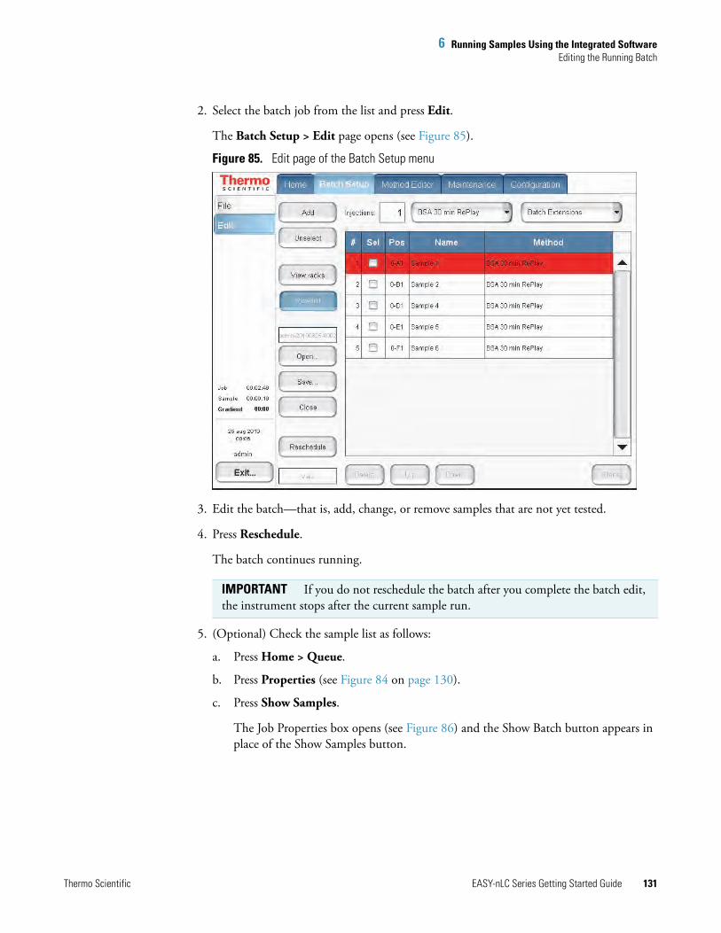
6 Running Samples Using the Integrated SoftwareEditing the Running Batch
Thermo Scientific EASY-nLC Series Getting Started Guide 131
2. Select the batch job from the list and press Edit.
The Batch Setup > Edit page opens (see Figure 85).
Figure 85. Edit page of the Batch Setup menu
3. Edit the batch—that is, add, change, or remove samples that are not yet tested.
4. Press Reschedule.
The batch continues running.
5. (Optional) Check the sample list as follows:
a. Press Home > Queue.
b. Press Properties (see Figure 84 on page 130).
c. Press Show Samples.
The Job Properties box opens (see Figure 86) and the Show Batch button appears in place of the Show Samples button.
IMPORTANT If you do not reschedule the batch after you complete the batch edit, the instrument stops after the current sample run.

6 Running Samples Using the Integrated SoftwareEditing the Running Batch
132 EASY-nLC Series Getting Started Guide Thermo Scientific
Figure 86. Sample list job properties on the Queue page
d. Click Close.

6 Running Samples Using the Integrated SoftwareTroubleshooting a Sample Run
Thermo Scientific EASY-nLC Series Getting Started Guide 133
Troubleshooting a Sample RunIf a problem occurs during a sample analysis, the EASY-nLC instrument displays the error in a pop-up box and stops the sample processing.
To troubleshoot an error condition that stops the sample processing
1. Press Cancel Batch.
2. Refer to the troubleshooting tips or follow the troubleshooting procedures in the EASY-nLC Series Troubleshooting and Maintenance Guide.
After you fix the problem, reschedule the batch (possibly changing the number of samples, their well positions, or both).


Thermo Scientific EASY-nLC Series Getting Started Guide 135
A
External Devices
To install and use the optional Advion RePlay device, follow the instructions in this appendix.
The RePlay device was specifically developed for nanoflow LC/MS analysis. It splits the sample from one injection, so a second analysis is provided with no additional sample required. The RePlay device consists of a primary column, a six-port valve, a flow sensor, tubing, a control panel, and a secondary column/emitter. It performs a second analysis of one sample without a reinjection, which allows for twice the analytical possibilities from every nanoLC injection. For more information, visit the Advion Web site:
www.advion.com/biosystems/replay/index.php
Thermo Fisher Scientific does not offer support for—or is in any way responsible for—the functionality of the RePlay device itself and the associated tubing and columns that it requires.
Note Currently, the EASY-nLC instrument supports only the Advion RePlay device. Thermo Fisher Scientific might choose to support additional external devices for use with the EASY-nLC instrument in future releases.
Contents
• Connecting the RePlay Device to the EASY-nLC Instrument
• Adding the RePlay Device to the EASY-nLC Device List
• Setting Up a Method with the RePlay Device
• Monitoring the Run of a RePlay Method
• Additional Run Time for a RePlay Experiment

A External DevicesConnecting the RePlay Device to the EASY-nLC Instrument
136 EASY-nLC Series Getting Started Guide Thermo Scientific
Connecting the RePlay Device to the EASY-nLC InstrumentBefore you can use the RePlay device with the EASY-nLC instrument, you must connect the contact closure cables and the solvent lines.
The Replay device has a remote port on its back panel and a six-port valve (see Figure 87) on its front panel.
Figure 87. Front panel of the Replay device (courtesy of the Advion Inc. Web site)
To connect the RePlay device to the EASY-nLC instrument
1. Turn off the EASY-nLC instrument.
2. Connect the Remote cable port on the back panel of the RePlay device to the Out3 pins on the back panel of the EASY-nLC instrument (see Figure 88).
Figure 88. RePlay device connection to the EASY-nLC contact closure port
Valve
Power In
Mech. Pumps/Accessory
Main Power
Peripheral Control
Ethernet
Electronics Normal
Service
Reset
Analog Input
StartIn
100 Base T
ReadyOut
1V MAX 10V MAX
StartOut
On230 V AC
10 A
A 5.5 MAX
A 5.5 MAX
Off
EASY-nLC contact closure port
Peripheral control port
LCQ Fleet™, LXQ™, or LTQ MS detector (right-side panel)
Remote cable connector
RePlay device (back panel)

A External DevicesConnecting the RePlay Device to the EASY-nLC Instrument
Thermo Scientific EASY-nLC Series Getting Started Guide 137
3. Connect the solvent lines to the valve on the front panel of the RePlay device (see Figure 89) as follows:
• Connect the output end of the EASY-nLC analytical column to position 5 of the RePlay valve.
• Connect position 4 of the RePlay valve to the secondary column/emitter.
Figure 89. Valve connections for the standard plumbing configuration
4. Turn on the EASY-nLC instrument.
Note For more information about connecting and using the RePlay device, refer to the Advion RePlay User’s Manual supplied by Advion Biosystems, Inc.
21
65
4
3Capture Cartridge
EASY-nLC columnSecondary column/emitter
Waste
Plugged
Flow sensor
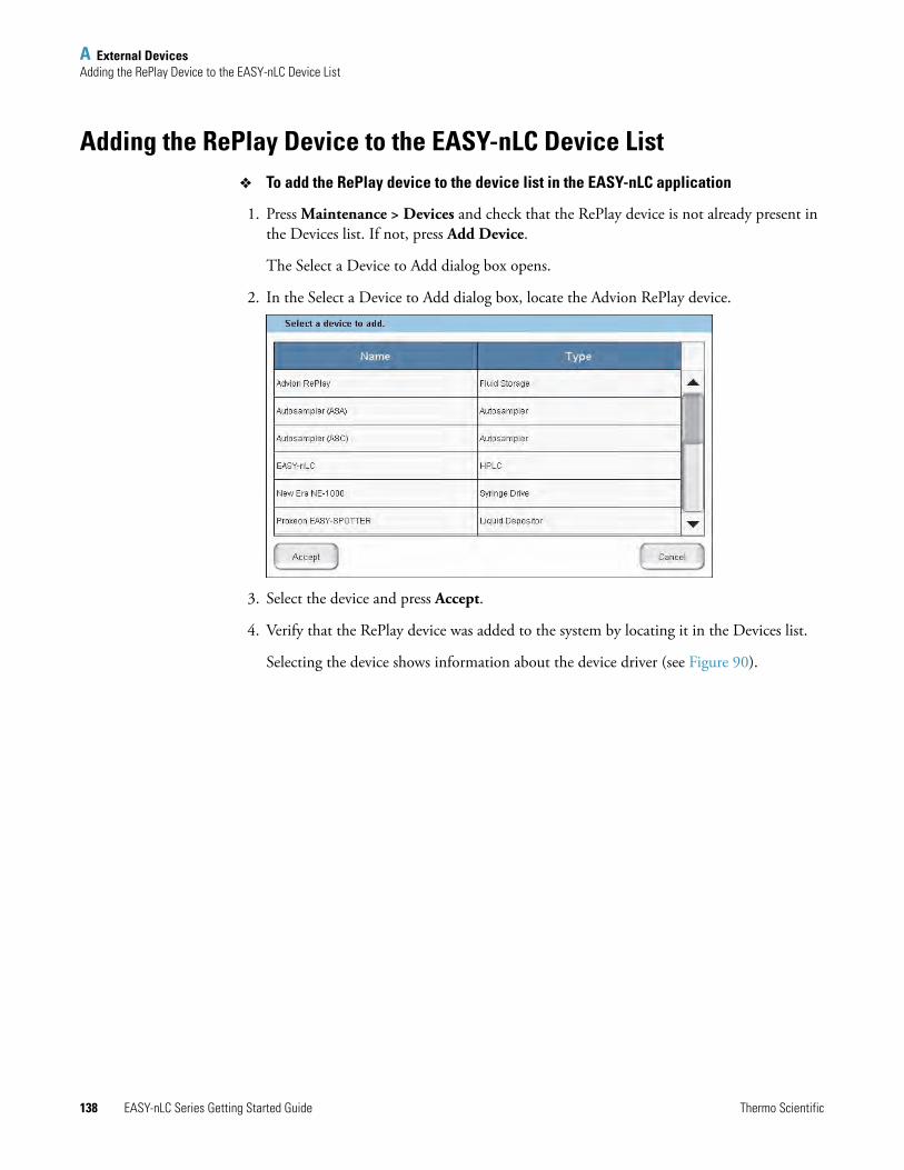
A External DevicesAdding the RePlay Device to the EASY-nLC Device List
138 EASY-nLC Series Getting Started Guide Thermo Scientific
Adding the RePlay Device to the EASY-nLC Device List To add the RePlay device to the device list in the EASY-nLC application
1. Press Maintenance > Devices and check that the RePlay device is not already present in the Devices list. If not, press Add Device.
The Select a Device to Add dialog box opens.
2. In the Select a Device to Add dialog box, locate the Advion RePlay device.
3. Select the device and press Accept.
4. Verify that the RePlay device was added to the system by locating it in the Devices list.
Selecting the device shows information about the device driver (see Figure 90).

A External DevicesSetting Up a Method with the RePlay Device
Thermo Scientific EASY-nLC Series Getting Started Guide 139
Figure 90. RePlay About tab under the Devices list
Setting Up a Method with the RePlay Device To set up a method with the RePlay device
1. To use the RePlay device, enable the method extension on page 1 of the Method Editor (you can also open an existing method and enable its extension).
An extra RePlay Method Editor page is now available (see Figure 91).
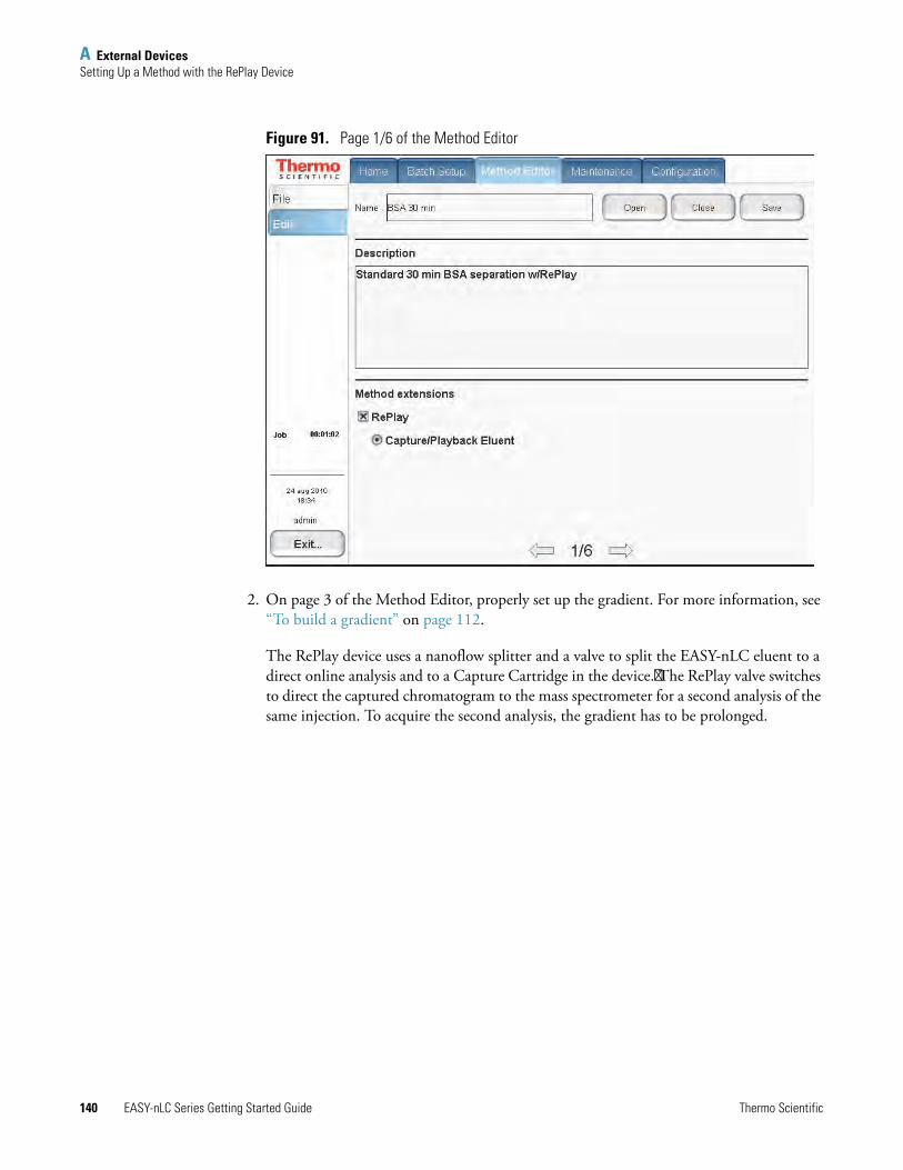
A External DevicesSetting Up a Method with the RePlay Device
140 EASY-nLC Series Getting Started Guide Thermo Scientific
Figure 91. Page 1/6 of the Method Editor
2. On page 3 of the Method Editor, properly set up the gradient. For more information, see “To build a gradient” on page 112.
The RePlay device uses a nanoflow splitter and a valve to split the EASY-nLC eluent to a direct online analysis and to a Capture Cartridge in the device. The RePlay valve switches to direct the captured chromatogram to the mass spectrometer for a second analysis of the same injection. To acquire the second analysis, the gradient has to be prolonged.

A External DevicesSetting Up a Method with the RePlay Device
Thermo Scientific EASY-nLC Series Getting Started Guide 141
3. On page 6, enter the playback delay relative to the MS START signal (which can be the start of either sample loading onto the columns or the start of the gradient, and set from the Configuration > Connections page).
This value, as shown in Figure 92, indicates how long into the gradient to switch back to playback mode. At the end of the gradient, the contact closure control reverts to capture mode.
Figure 92. RePlay Playback Delay setting

A External DevicesMonitoring the Run of a RePlay Method
142 EASY-nLC Series Getting Started Guide Thermo Scientific
Monitoring the Run of a RePlay MethodThe readback for a RePlay method displays Capture or Replay.
To monitor the run of a RePlay method
1. When running a sample using a method with the RePlay extension, press Home > Overview.
2. View the RePlay (“RP”) mode readback in the center status box (see Figure 93).
Figure 93. RePlay method readback
RePlay method readback

A External DevicesAdditional Run Time for a RePlay Experiment
Thermo Scientific EASY-nLC Series Getting Started Guide 143
Additional Run Time for a RePlay ExperimentFor a typical RePlay application—injecting and loading 5 μL of sample with a gradient of 60 minutes + 30 minutes RePlay—the full timing is as follows:
• 2 minutes – Refilling pumps at 100 μL/min
• 2 minutes – Injecting 5 μL at 20 μL/min and waiting for pressures to settle
• 12 minutes – Loading the sample onto the analytical column with 15 μL at 1.25 μL/min
• 60 minutes – Gradient + autosampler wash
• 30 minutes – RePlay while also reequilibrating the analytical column
In total, you can achieve an MS utilization rate of close to 85 percent (90/106), despite the fact that the EASY-nLC/MS system cannot overlap (parts of ) two runs in parallel.


Thermo Scientific EASY-nLC Series Getting Started Guide 145
B
Downloading the Touch-Screen Software
The EASY-nLC instrument has a built-in computer with instrument control software and a touch-screen interface. Occasionally, Thermo Fisher Scientific releases new versions of the touch-screen instrument control software.
You can upgrade the software by downloading the firmware files from the EASY-nLC User Support Zone as described in this appendix or by connecting the instrument to the remote server as described in the EASY-nLC Series Maintenance and Troubleshooting Guide.
To upgrade the touch-screen instrument control software, follow these procedures in order.
1. Downloading Software Files from the EASY-nLC User Support Zone
2. Installing Firmware Files
3. Resetting the Mass Spectrometer Selection
Downloading Software Files from the EASY-nLC User Support ZoneThermo Fisher Scientific provides upgrades of the touch-screen software for EASY-nLC instruments from the EASY-nLC user support zone. To download the software, you need the serial number of your EASY-nLC instrument.
To download the latest software for the EASY-nLC instrument
1. Record the serial number on the instrument’s back panel (see Figure 5 on page 6).
You use the serial number when you download software from the EASY-nLC User Support zone.
Note Thermo Fisher Scientific recommends that you upgrade the touch-screen software by connecting the EASY-nLC instrument to the remote server as described in the EASY-nLC Series Maintenance and Troubleshooting Guide.
Note If the software version is earlier than version 2.7.8, you must first upgrade to version 2.7.8, and then upgrade to version 3.1 or later.

B Downloading the Touch-Screen SoftwareDownloading Software Files from the EASY-nLC User Support Zone
146 EASY-nLC Series Getting Started Guide Thermo Scientific
2. Go to this Web site:
http://www.proxeon.com/support_and_service/easy_nlc/introduction/
The EASY-nLC User Zone Web site opens (see Figure 94).
Figure 94. EASY-nLC User Zone Web site
3. To access the Support and Service site, click My Account/Login in the Navigation pane. Then, on the Log In page, do one of the following (see Figure 95):
• If you are a new user, click Sign Up and follow the instructions.
Figure 95. Log In area of Log In page
• If you are a registered user, enter your user name and password. Then, click Login.
Navigation pane

B Downloading the Touch-Screen SoftwareDownloading Software Files from the EASY-nLC User Support Zone
Thermo Scientific EASY-nLC Series Getting Started Guide 147
4. Under Support and Service in the Navigation pane, click EASY-nLC User Zone.
The downloads page opens (see Figure 96).
Figure 96. Download selections
5. Type the serial number of the EASY-nLC instrument in the appropriate box under either Downloads for EASY-nLC 1000 Systems or Downloads for EASY-nLC II Systems.

B Downloading the Touch-Screen SoftwareDownloading Software Files from the EASY-nLC User Support Zone
148 EASY-nLC Series Getting Started Guide Thermo Scientific
6. Click REGISTER PRODUCT KEY.
The download selections appear (see Figure 97).
Figure 97. Download selections
7. Click to the left of the software version that you want to download.
Links to the downloadable files appear (see Figure 98).
Figure 98. Downloadable software and compatible manuals

B Downloading the Touch-Screen SoftwareDownloading Software Files from the EASY-nLC User Support Zone
Thermo Scientific EASY-nLC Series Getting Started Guide 149
8. Click EASY-nLC Software v.x.x.x.
The File Download dialog box opens (see Figure 99).
Figure 99. File Download dialog box
9. Click Save and copy the firmware file to the root directory of a USB memory stick.
IMPORTANT When you copy the firmware file to a USB memory stick, do the following:
• Make sure that you place the file into the root directory. The EASY-nLC instrument cannot recognize the firmware file when it is located in a folder.
• Save only one firmware file to the root directory of the memory stick.

B Downloading the Touch-Screen SoftwareInstalling Firmware Files
150 EASY-nLC Series Getting Started Guide Thermo Scientific
Installing Firmware Files To install the latest firmware file for the EASY-nLC touch-screen software
1. Turn on the EASY-nLC instrument and log in as an administrator.
2. Plug the USB memory stick into the USB port on the back panel of the EASY-nLC instrument.
3. On the Home > Overview page of the touch-screen application, press Exit.
The Administrator dialog box opens.
4. Press Stop Application.
The Stop Application dialog box opens.
5. Press Accept.
Two large buttons appear in place of the Home > Overview screen: START and UPGRADE SOFTWARE.
6. Double-tap UPGRADE SOFTWARE.
The download process begins. When the download process is complete, the START button reappears.
7. When the download process is complete, remove the USB memory stick from the instrument’s back panel.
8. Double-tap START.
When the software upgrade is complete, the Home > Overview screen opens.

B Downloading the Touch-Screen SoftwareResetting the Mass Spectrometer Selection
Thermo Scientific EASY-nLC Series Getting Started Guide 151
Resetting the Mass Spectrometer SelectionWhen you download the touch-screen application to the EASY-nLC instrument’s built-in computer, the application resets the selection in the Instrument (Cable No.) list to None on the Configuration > Connections page.
To set up the mass spectrometer connection
1. From the Home Overview page of the touch-screen software, press Configuration > Connections.
The Configuration > Connections page opens (see Figure 100).
Figure 100. Connections page of the Configuration menu (touch-screen software version 3.1)
IMPORTANT Take care to make the appropriate contact closure selections for both the EASY-nLC instrument and the mass spectrometer. If you do not make the appropriate selections for the EASY-nLC instrument and the mass spectrometer, the mass spectrometer does not receive the contact closure signal from the LC system during a run and remains in the Waiting for Contact Closure state.
For an LTQ Series mass spectrometer, in the LTQ Series Configuration dialog box – Inlet view of the Thermo Foundation > Instrument Configuration window, keep the default selection of Any Edge in the Contact Closure type area.
The TSQ Series instrument control software does not have any contact closure settings.
Note The Contact Closer page of the Xcalibur Instrument Setup window – LTQ mass spectrometer view enables you to set up a contact closure signal from the Start Out pins of LTQ mass spectrometer to another device such as a fraction collector. This page does not apply to the contact closure signal sent from the EASY-nLC instrument to the mass spectrometer’s Start In pins.

B Downloading the Touch-Screen SoftwareResetting the Mass Spectrometer Selection
152 EASY-nLC Series Getting Started Guide Thermo Scientific
2. Make the following selections for a Thermo Scientific mass spectrometer:
• In the Instrument (cable no.) list, select Thermo Scientific (LC160).
• In the Protocol list, select One-way.
• In the State at Start list, select Open.
3. In the Start At list, select Gradient or Sample Loading.
• If you want data acquisition to start when the mobile phase gradient starts, select Gradient.
• If you are running the instrument in the one-column mode and you want data acquisition to start when the instrument loads the sample onto the analytical column, select Sample Loading.
4. In the Signal Width box, keep the default signal width of 1 second.
A signal width of 1 second is sufficient for a Thermo Scientific mass spectrometer.
Note By setting the Start At value to the start of the sample loading step, you might be able to acquire data for early-eluting peptides that would not ordinarily bind to the column material and thus be missed from the actual gradient. Moving the Start At point to the start of the sample loading step can lead to small retention time variations, due to possible differences in pressure buildup before the A/B mixing starts in the actual gradient.

Thermo Scientific EASY-nLC Series Getting Started Guide 153
I
Aaccessing
files on the instrument’s hard drive 45, 68support server 46
accounts, adding new users 72acetonitrile, solvent requirements 81adapter union, zero-dead-volume 95, 97admin folder, accessing 45, 69admin, changing password 71Administrator dialog box 150air segments, sample pickup 20alphanumeric text, entering 52analytical column
column setup options 8equilibration step, method 22installing 90preparation for use 105
application version 55Automatic Flow Control (AFC) description 31autosampler
sample pickup method parameters 110tray compartment, accessing 4wash step, method 30, 116
Bback panel, instrument 6, 40back pressure
analytical column rating 106precolumn rating 104
backup, system 75Batch Setup menu 58batches
editing on the Home > Queue page 130setting up and scheduling 119starting 125
beaker, plastic waste 83black knurled nut tool, nanoViper fitting 102
bottlesfor solvents A and B, filling 82wash 83
Ccables
contact closure 42Ethernet 43power cord 41
carryover, reducing 117changing the administrator password 71check valves, description 14checking, solvent levels 79cleanup, computer file system 75columns
See analytical column or precolumncompliance
FCC xiiregulatory xii
compliance, electromagnetic xiv, xvicomponents, system 2computer, embedded
cause of damage to 41purging data from 75
Configuration menu 61configuring
devices 76global settings 76RePlay 138
connectingadd-ons 47contact closure cable 42mouse and keyboard 47nanoViper fittings 102to line power 41to the data system computer 44to the network 68
Index

154 EASY-nLC Series Getting Started Guide Thermo Scientific
Index: D
contact closurecables, ordering 42configuration setting 66with the mass spectrometer 42, 151
creatinga method 109new user accounts 72
Custom Wash, sample pickup system 117Cycles parameter, autosampler wash 117
Ddaily maintenance 79data system computer
connecting to the Ethernet switch 44connecting to the laboratory LAN port 44using to access folders on the system computer 45
data types, graphs 128data, removing excess 75Declaration of Conformity xiv, xvidevices, configuring 76dimensions, EASY-nLC system 37downloading the touch-screen software 145
EEASY-nLC User Zone Web site 146EASY-Spray source, column assembly for 95Eject Plate button, using 52, 83electromagnetic compatibility xiiemitter, installing 94equilibrating
analytical column 22, 105precolumn 22, 103
Ethernet cables, connectingdata system computer 44EASY-nLC system to the intranet 45EASY-nLC system to the support server 46
Ethernet switch 44Exit button 64
FFCC compliance xiifile system, computer cleanup 75firewalls, laboratory network access 39flow rate
gradient 112measuring 12monitoring 127sample loading 111sample pickup 111
flow sensors, description 12formic acid, solvent requirements 81
Gglobal configuration settings 76gloves, wearing 95gradient
delay volume 29method step 29setting up the method 112
graphical data types 128grounding requirements 41
HHome > Overview page 53Home menu 57humidity specification 39
Iinjections
number per sample 122pickup sample step 20sample pickup volume 110
Insert Plate button, using 84insert, needle wash 4, 84Intelligent Flow Control (IFC) system description 32interface layout 55Internet access 39ion source, power requirements for 39
Kkeyboard connection 47keyboard, touch-screen software 52
LLC connections
EASY-nLC 1000, connecting to 96EASY-nLC II, connecting to 96tools and supplies 95
leaks, testing the nanoViper connections for 102lifting instructions 36Load Speed Protection option 33, 77logging in to the application 62Logo icon, Thermo Scientific 55Loop Volume box 77

Thermo Scientific EASY-nLC Series Getting Started Guide 155
Index: M
MMaintenance menu 60maintenance, daily 79manuals, EASY-nLC viiimass spectrometer, contact closure
configuration setting 66hardware connection 42
menu structure 57menus
Batch Setup 58Configuration 61Home 57Maintenance 60Method Editor 59structure 56
Method Editor menu 59method, LC
accessing from another computer 45, 69analytical column equilibration parameters 115gradient table 112method editor, starting 109precolumn equilibration parameters 114
microwell plates, preparing samples 107mixing Tee
connections 14readback 53–54
monitoring the run 126 See also RePlay, monitoring the run
mouse connection 47
NNanoFlex source, column assembly for 90nanoViper fittings, using 102needle wash insert 4, 84network card, installing in data system computer 44network connection 68noise and interference, cause of 41None, Instrument list selection 151numeric keypad 52
Oone-column setup
configuration check box 76description 9installation
for a NanoFlex source and an EASY-nLC 1000 instrument 93
for an EASY-Spray source and an EASY-nLC 1000 instrument 100
for an EASY-Spray source and an EASY-nLC II instrument 96
ordering informationcolumns 92contact closure cable 42fittings 97product order code, instrument 7sleeves, PEEK 91, 95solvents 81venting Tee 92, 95, 100Viper union 95ZDV union 91
overtightening nanoViper fittings 102
Ppassword
changing 71initial 62
port 22, firewall setup for 39, 46power
requirements 39turning off 64
power cord, connection and specifications 41Power Down button 64power-save feature, Ethernet switch 44precolumn
equilibration step, method 22, 114preparation for use 103
Prepare Gradient step 26preparing
solvent bottles and waste containers 80well plates 107
pressure sensors 11pump, flow control description for 31purging and flushing pumps 86
Qquadrant selection box, 384-well plate 123
Rregulatory compliance xiiremote desktop connections 44remote support 46RePlay
additional run time 143configuring 138connecting to EASY-nLC 135monitoring the run 142
rotary valves, description 13run time, excessively long 10running batch, editing 130

156 EASY-nLC Series Getting Started Guide Thermo Scientific
Index: S
Ssafety
handling emitters 94precautions for the EASY-nLC system ixstandards (EMC) xvi
safety standards xiisafety standards (EMC) xivsample
loading, method parameters 111pickup method parameters 110
sample loopbypassed during gradient program 29configuring 77maximum capacity 20washing 30
sample runspredefined steps 15troubleshooting 133
Secure Shell (SSH) network protocol 39sequence, injection 119serial number, instrument 147sharp objects, emitter 94signal width 152sleeves, PEEK 95sluggish system performance 75software upgrades 145solvent A and B bottles, preparing 82solvents
checking levels 79filtering 81ordering Fisher Scientific solvents 81
solvent-side check valve 14Source column, autosampler wash 117Standard option, autosampler wash 117Start At list, Configuration > Connections page 152Start button, green 85, 127starting the EASY-nLC 50Stop button, red 85, 127, 130stopping sample acquisition 130support server, setting up the hardware connections 46system overview, monitoring 126
Ttechnical support, contacting xiTees
mixing 11, 14venting 5, 8–9, 14
temperature, specification 39terms used in this guide 55Thermo Scientific logo icon 55
tightening tool, nanoViper fitting 102time setting 74tools and supplies, connecting the LC 95touch screen, using 51trap column
See precolumntray compartment, accessing 4, 52troubleshooting, sample runs 133turning off the EASY-nLC 64two-column setup
description 8installation
for an EASY-nLC 1000 instrument and a NanoFlex source 92
for an EASY-nLC 1000 instrument and an EASY-Spray source 101
for an EASY-nLC II instrument and an EASY-Spray source 97
Uunions
Viper 95zero-dead-volume adapter union 95, 97
upgrades, software 145URLs
consumable parts xicustomer manuals viiiEASY-nLC User Zone Web site 146
USB flash drive with manuals viiiUSB ports, EASY-nLC 7user permissions 70
Vvalves
check valves, description 14rotary valves, description 13
venting Teeconnections 5, 9, 91–93, 95–96, 100–101function 8, 14, 83purpose 22
version, application 55vials, preparing sample 107Viper union 95volume, maximum
custom wash solvent volume per step 117sample loading step 111sample pickup step 110

Thermo Scientific EASY-nLC Series Getting Started Guide 157
Index: W
Wwash bottles
description 4preparing 83
wash step, autosampler 30, 116waste beaker, installing 83Waste In tubing 93waste-side check valve 14water, solvent requirements 81well plates, preparing 107Windows Explorer 69
Zzero-dead-volume adapter union 95, 97
