westinghouse i - electrical part manual s i.l 41-491h ... distance characteristic: kd-3 phase unit...
TRANSCRIPT
Westinghouse I.L 4 1 -49 1 H
INSTALLATION • OPERATION • MAINTENANCE
INSTRUCTIONS TYPES KD AND KD-1
COMPENSATOR DISTANCE RELAYS
T A B L E OF C O N T E N T S
Page
APPLICATI ON. . . . . . . . . . . . . . . . . . . 3
CONSTRUCTION . . . . . . . . . . . . . . . . . 3 Compensator • . . . • . • . . . . . . . . . . • . 3 Auto-Transformer . . . . . " . . . • • . . . . . 3 Tripping Unit • . . . • . • . • . • . . . . • . . . 4 Indicating Contactor Switch Unit (ICS) . • • 5
O P ERATION . . . . . . . . . . . . . . . . . . . . 5 Three Phase Unit • • • . • • • • • • . • • • . . 8 P hase-to-Phase Unit . • . . . . . . . . . . . . 8
CHARACTERISTICS Distance Characteristic: P hase-to-Phase Unit 9 Sensitivity Phase-to- Phao;e Unit . . . . . . . 10 Distance Characteristic: K D , 3 Phase Unit 11 Sensitivity: K D, 3 Phase Unit . . • . . . . . 11 Distance Characteristic: KD-1 3 P hase Unit 11 Sensitivity: K D-1 3 Phase Unit . . . . • . . . 13 General Characteristics . . . . . . . . . • • . . 13
TIME CURV E S AND BURDEN DATA . . . . . 13 Operating Time . • . • . • . . . . • . . . . . . . 13 Current Circuit Rating in Amperes ...... 13 Burden . . . . . . . . . . . . . . . . . . • . • . • • 13 Trip Circuit Constants . . . . . • . • . • . • . 13
SETT I NG CALCULATIONS . . . . . . . . . . . 16
SETTING T H E RELAY . . . . . . . . . . . . . . 16 Compensators (T, T A• T8, and Tc) . . . . • 18 Auto-Transformer Primary (S, SA, and Sc) • 18 Auto-Transformer Secondary (M, M A•
and Me) • . . . . . . . • . . . . . • . . . . . . . 18
SUPERSEDES LL. 4 1 -49 1 G *Denotes change from superseded issue.
Page
R8 Setting s . . . . . . • . • . . . . . . . . . . . 18 Line Angle Adjustment . . . . . • . . . . . . . 18 Indicating Contactor Switch . . . . . . . . • . 18
I N STALLATION . . . . . . . . . . . . . . . . . . 21
EXTERNAL CO NNECTIONS . . . . . . . . . . 21
RECEI VING ACCEPTANCE . . . . . . . . . . . 23 Distance Units . . • . . . . • • . . . . . . . • • 23 Indicating C ontactor Switch (ICS) . . . . • • 23
ROUTINE MAI NTENANCE . . . . . . . . . . . . 23 Distance Units . . . . . . . . . . . . . • . . . • 23 Indicating Contactor Switch . . . . . . . • . . 24
REPAIR CALI BRATION . . . . . . . . . . . . . 24 Auto-Transformer Check . . . . . . . • . . . . . 24 Distance Unit Calibration .... . ...... 24
I. Three P hase Unit ......... ..... 24 11. Phase-to-Phase Unit • • • • • • . . • • • . 25
Ill. Compensator Check • . . • . . . . . . . . • 27 IV. Overall Check • • • • • • • . • • • • • . • . • . . • 27
NOMENCLATURE FO R R ELAY TYPES KD AND KD-1 . . . . . . . . . . . . . . 30
SWITCHBOARD T ESTING WITH KD AND KD- 1 RELAYS . . . . . . . . . . . . . . . 32 Potential Circuit C heck • . . . . . . . . . . • . 32 Current Verification . • • . . . . . . . . . . . 32
Current Identification ....... ....... 32
EFFECTIVE OCTO BER 1 965 www . El
ectric
alPar
tMan
uals
. com

N -1 -< "'tJ m "' " 0 > z
C2c ......._ ·�.._: l&P:UW 0 " 0 ' -"' m r-> -< "'
TA
RB TB
RMA RMc RMC
M
KD Relay KD-1 Relay KD & KD-1 Relays
Fig. 1. Type KD & KD-1 Relays Without Case.
www . El
ectric
alPar
tMan
uals
. com
TY P E S KD AND KD-1 R E LAYS __________________________ I._L_. _41_-4_9_1 H
CAUTIOt·l: Before putting protective relays into service make sure that all moving parts operate freely, inspect the contacts to see that they are clean and close properly, and operate the relay to check the settings and electrical connections.
APPLI CA T IO N
The type KD relay (Figure 1), is a polyphase compensator type relay which provides a single zone of phase protection for all three phases. It provides instantaneous tripping for all combinations of phaseto-phase faults, two-phase-to-ground faults, and threephase faults.
The type KD-1 relay, (Figure 1), is similar to the KD relay except that its characteristic impedance circle includes the origin. This relay is applied as a third zone of protection in pilot relaying schemes but it may also be used for time delay tripping in straight distance relaying.
Both the KD and KD-1 are available with indicating contactor switches with either a 1 ampere or a 0 . 2/ 2. 0 ampere rating. The 1 ampere rating is recommended for all directional comparison applications and for most distance relaying applications. The 0 . 2/ 2.0 ampere rating is recommended for distance relaying where a lockout relay is energized or where a high impedance auxiliary tripping relay is utilized.
Refer to I. L. 41-911 for a description of how KD
& KD-1 relays are used in directional comparison
blocking systems.
For time-distance applications the KD & KD-1
relays are used with either the TD-2 a-c current
operated timer, or with the TD-4 d-e transistorized timer. See Figs. 17 and 18 for the external schematics
for 3 zone protection, using the TD-2 and TD-4 re
lays, respectively. For further discussion see ''Ex
ternal Connections."
Use fault detectors to supervise the trip circuit for those applications where the relays can be de
energized without attendant opening of the 52a con
tact. Otherwise undesired tripping occurs. A S/11878395
three unit SC Relay ( 2-8 amperes) in the type FT3 2
case or a SII288B714A18 three unit ITH Relay (4-8
amperes) in the type FT 11 case is recommended.
CO N S T RU C T I O N
The types KD and KD-1 relays each consist of
four single air gap transformers (compensators), three tapped auto-transformers, two cylinder type operating units, and an ICS indicating contactor switch. The KD relay also contains an adjustable reactor not
used in the KD-1.
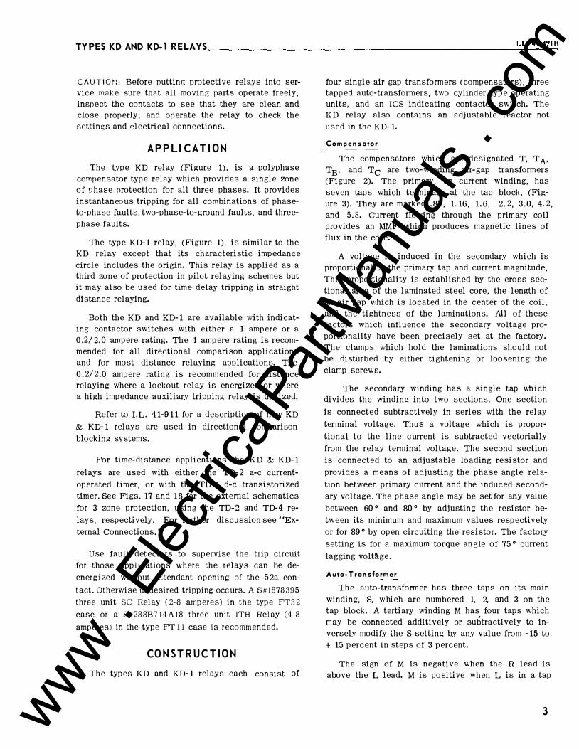
Compensator
The compensators which are designated T, T A• TB, and Tc are two-winding air-gap transformers (Figure 2). The primary, or current winding, has seven taps which terminate at the tap block, (Figure 3). They are marked .87, 1.16, 1.6, 2. 2, 3.0, 4. 2, and 5.8. Current flowing through the primary coil provides an MMF which produces magnetic lines of flux in the core.
A voltage is induced in the secondary which is proportional to the primary tap and current magnitude, This proportionality is established by the cross sectional area of the laminated steel core, the length of an air gap vihich is located in the center of the coil, and the tightness of the laminations. All of these factors which influence the secondary voltage proportionality have been precisely set at the factory. The clamps which hold the laminations should not be disturbed by either tightening or loosening the clamp screws.
The secondary winding has a single tap which divides the winding into two sections. One section
is connected subtractively in series with the relay
terminal voltage. Thus a voltage which is propor
tional to the line current is subtracted vectorially
from the relay terminal voltage. The second section is connected to an adjustable loading resistor and
provides a means of adjusting the phase angle rela
tion between primary current and the induced secondary voltage. The phase angle may be set for any value
between 60 o and 80 o by adjusting the resistor between its minimum and maximum values respectively
or for 89 o by open circuiting the resistor. The factory
setting is for a maximum torque angle of 75 o current
lagging voltrtge.
Auto-Transformer
The auto-transformer has three taps on its main winding, S, which are numbered 1, 2, and 3 on the tap block. A tertiary winding M has four taps which may be connected additively or subtractively to inversely modify the S setting by any value from -15 to + 15 percent in steps of 3 percent.
The sign of M is negative when the R lead is above the L lead. M is positive when L is in a tap
3 www . El
ectric
alPar
tMan
uals
. com

TYPESKDANDKD-1 RELAYS-----------------------------------------------------
4
PRIMARY LAMINATED CORE
I
Fig. 2. Compensator Construction.
CONNECTOR SCREW
SOCKETS FOR COMPENSATORS TAPS
LEAD "R"
INSERTS
s ...
location which is above the tap location of the R lead. The M setting is determined by the sum of per unit values between the R and L lead. The actual per unit values which appear on the tap plate between
taps are 0, .03, .06, and .06.
The auto-transformer makes it possible to expand the basic range (T = 0.87 to 5. 8 ohms) by a multiplier
of 1 8 . Therefore, any relay ohm setting can ± M
be made within ± 1. 5 percent from 0. 75 ohms to 20 ohms by combining the compensator taps T, T A, TB• and Tc with the auto-transformer taps S and M, SA
and MA. and Sc and Me.
Tripping Unit
The device which acts to initiate tripping is a four-pole cylinder unit which is connected open delta and operates as a three-phase induction motor. Contact-closing torque is produced by the unit when the voltage applied to its terminals has a negative-phase sequence. Closing torque for the relay forces the moving contact to the left hand side as viewed from the front of the relay. Contact-opening torque is produced when positive-phase sequence voltages are applied. Hence, the cylinder unit has restraint or operating torque as determined by the phase sequence of the voltages applied to its terminals.
}3 PHASE UNIT SETTINGS
PHASE-TO-PHASE UNIT SETTINGS
Fig. 3. Tap Plate.
www . El
ectric
alPar
tMan
uals
. com
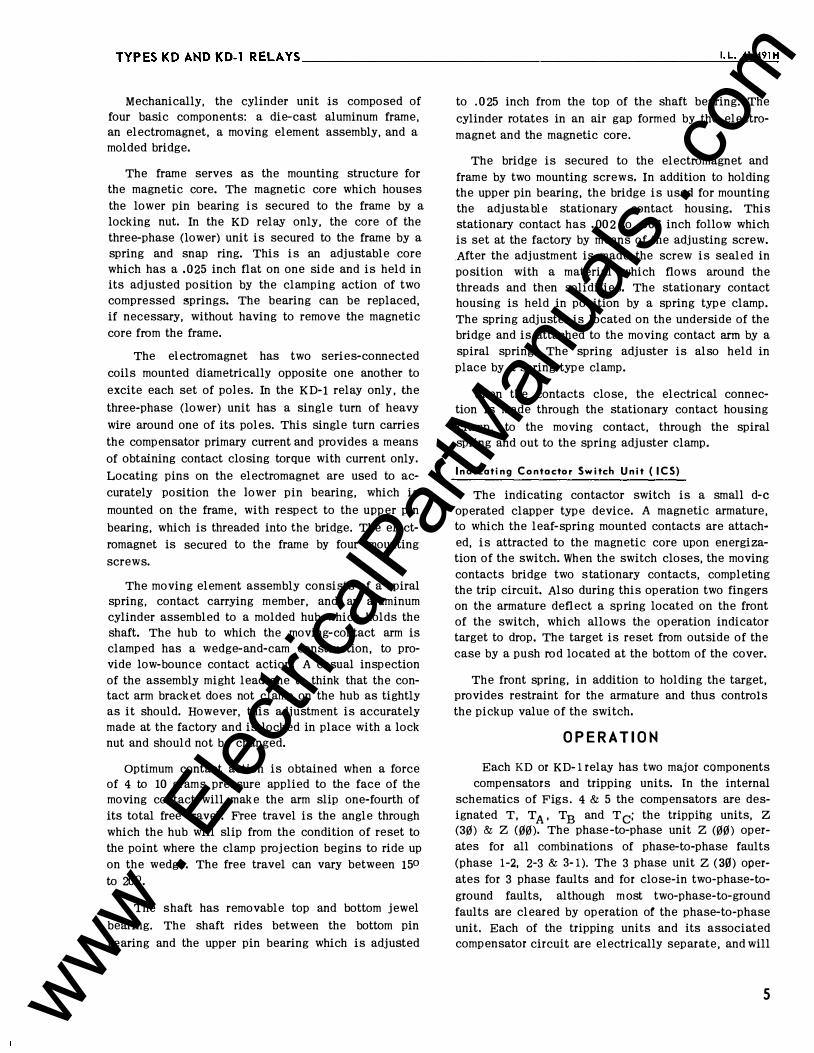
Mechanically, the cylinder unit is composed of four basic components: a die-cast aluminum frame, an electromagnet, a moving element assembly, and a molded bridge.
The frame serves as the mounting structure for the magnetic core. The magnetic core which houses
the lower pin bearing is secured to the frame by a locking nut. In the KD relay only, the core of the three-phase (lower) unit is secured to the frame by a spring and snap ring. This is an adjustable core which has a .025 inch flat on one side and is held in its adjusted position by the clamping action of two compressed �prings. The bearing can be replaced, if necessary, without having to remove the magnetic
core from the frame.
The electromagnet has two series-connected
coils mounted diametrically opposite one another to
excite each set of poles. In the KD-1 relay only, the
three-phase (lower) unit has a single turn of heavy
wire around one of its poles. This single turn carries
the compensator primary current and provides a means
of obtaining contact closing torque with current only.
Locating pins on the electromagnet are used to ac
curately position the lower pin bearing, which is
mounted on the frame, with respect to the upper pin
bearing, which is threaded into the bridge. The elect
romagnet is secured to the frame by four mounting
screws.
The moving element assembly consists of a spiral spring, contact carrying member, and an aluminum cylinder assembled to a molded hub which holds the shaft. The hub to which the moving-contact arm is clamped has a wedge-and-cam construction, to provide low-bounce contact action. A casual inspection of the assembly might lead one to think that the contact arm bracket does not clamp on the hub as tightly as it should. However, this adjustment is accurately made at the factory and is locked in place with a lock nut and should not be changed.
Optimum contact action is obtained when a force of 4 to 10 grams pressure applied to the face of the moving contact will make the arm slip one-fourth of its total free travel. Free travel is the angle through which the hub will slip from the condition of reset to the point where the clamp projection begins to ride up on the wedge. The free travel can vary between 150 to 20°.
The shaft has removable top and bottom jewel
bearing. The shaft rides between the bottom pin
bearing and the upper pin bearing which is adjusted
to . 0 25 inch from the top of the shaft bearing. The
cylinder rotates in an air gap formed by the electromagnet and the magnetic core.
The bridge is secured to the electromagnet and
frame by two mounting screws. In addition to holding the upper pin bearing, the bridge is used for mounting the adjustable stationary contact housing. This stationary contact has .00 2 to .006 inch follow which is set at the factory by means of the adjusting screw. .After the adjustment is made the screw is sealed in position with a material which flows around the threads and then solidifies. The stationary contact housing is held in position by a spring type clamp. The spring adjuster is located on the underside of the bridge and is attached to the moving contact arm by a spiral spring. The spring adjuster is also held in place by a spring type clamp.
When the contacts close, the electrical connection is made through the stationary contact housing
clamp, to the moving contact, through the spiral spring and out to the spring adjuster clamp.
Indicating Contactor Switch Unit ( ICS)
The indicating contactor switch is a small d-e operated clapper type device. A magnetic armature, to which the leaf-spring mounted contacts are attached, is attracted to the magnetic core upon energization of the switch. When the switch closes, the moving contacts bridge two s tationary contacts, completing the trip circuit. Also during this operation two fingers on the armature deflect a spring located on the front of the switch, which allows the operation indicator target to drop. The target is reset from outside of the case by a push rod located at the bottom of the cover.
The front spring, in addition to holding the target, provides restraint for the armature and thus controls the pickup value of the switch.
O P E R A T I O N
Each KD or KD-1 relay has two major components compensators and tripping units. In the internal
schematics of Figs, 4 & 5 the compensators are designated T, TA , TB and Tc; the tripping units, z (30) & Z <00). The phase -to-phase unit Z (00) operates for all combinations of phase-to-phase faults (phase 1-2, 2-3 & 3-1). The 3 phase unit Z (30) operates for 3 phase faults and for close-in two-phase-to
ground faults, although m ost two-phase-to-ground faults are cleared by operation of the phase-to-phase unit. Each of the tripping units and its associated compensator circuit are electrically separate, and will
5 www . El
ectric
alPar
tMan
uals
. com

0.
c' �3Ic )o
11l0
II
CHASSIS OPE.UTED SHOi<TING SWITCH
,( CURRENo TEST JACI(
.02 MFD. 150 � I NO i CAT I HG C0H TACT ('h:
;; I; TANCE UNIT -!----+-+--------� SWI 1Ct1 ( UPPER UNIT) 30 DISTA�CE "NIT
A I ol GAP
I I
HANSFORMER ---+-'--+-----
L '- ' 1 \ l s II LTHRtE AIR GA>
TRANSFORMERS
9 I I 1 \"-T I 1 \ n·! I AUTO-TRANSF;,RI�Ef
Lr�������:q @ @ @:
RED HANDLE
TEST Swi!C:I
TERM i H.�L
FRONT vIEW PH,i PH.2 PH, ?I
183A507 Fig. 4. Internal Schematic of Type KD Relay with 1.0 ampere I.C.S. in the
Type FT42 Case. (Relay with 0.2/2.0 ampere I.C.S. unit has identical
w iring except that the I.C.S. coil is tapped on terminal 10.)
li"&
CIIASS IS OPERATED SHORTING SWITCH
x.- I I i +-CIIIIREMT TEST JACK
DISTANCE UIIIT -�--f.-----I MDI CATIMG CONTACTOR SWITCH ( UPPER UIIT)
3GI DISTANCE UMIT
AIR GAP TUMSFORMt:R ---+---''-----"-
' • l ' 1 ' I I I THREE AIR GAP TRANSFORMERS
� I I 1 \n T I \ n-�� AUTO-TRANSFORMER
FIIOIIT VIEW PH.I PH.2 PH.3
RED HANDLE
TEST SWITCH
183A527 Fig. 5. Internal Schematic of Type KD-1 Relay with 1.0 ampere I.C.S. in the
Type FT42 Case. (Relay with 0.2/2.0 ampere I.C.S. unit has identical
wiring except that the I. C.S. coil is tapped on terminal 10.)
-1 -< "tt m Vt "' 0 )> z 0 "' 9 -::a m r)> -< Vt
www . El
ectric
alPar
tMan
uals
. com

TYPESKDANDKD-1RELAYS ________________________________________________ I._L_.4_1 _-4_91_H
BUS
K-DAR RELAY LOCATION BEING
C ONSIDERED
ZONE I RELAY SET 90'l'o OF
LINE SECTION
BALANCE POINT _/ I I I I I
BUS
FAULT BEHIND RELAY FAULT WITHIN BALANCE POINT FAULT AT BALANCE POINT FAULT BEYOND BALANCE POINT X
v, �-_JC-I1Zcl l��} rl ' \ ---+-��=�_,
'
�2Y \\ -r z //�(<---+�
_ _::, I C L__
( D )
v2 Vy
( C) ( B)
NOTE: THE VOLTAGE TRIANGLES AT EACH FAULT LOCATION (A,B,CSD) REPRESENT THE VOLTAGES SEEN BY THE K-DAR RELAY TERMINAL LOCATED AT THE SHADED BREAKER FOR 3 PHASE FAULTS O C C URING AT EACH LOCATION (A,B,CSD)·
A)
407C459 Fig. 6. Voltage and Current Conditions for the Three-Phase Unit at the Shaded Breaker for Three-Phase Faults at Various
Locations.
I2
I3
BUS
I I I
ZONE I RELAY SET 90% OF
Ll NE SECTION
BALANCE POINT_/ I I I
BUS
23 FAULT BEHIND RELAY 23 FAULT WITHIN BALANCE POINT 23 FAULT AT BALANCE POINT 23 FAULT BEYOND BALANCE POINT
v3
Vz
I X I X I X I3
I3
Vy I v3 v z
Vz Vz
I I I2 L....-..1 -I2 Zc I2 -r2 zc
-r3zc
( D) ( C) ( B)
NOTE: THE VOLTAGE TRIANGLES AT EACH FAULT LOCATION (A,B,CSD) REPRESENT THE VOLTAGES SEEN BY THE K-DAR RELAY TERMINAL LOCATED AT THE SHADEO BREAKER FOR ; TO � FAULTS AT EACH LOCATION
CA,B,C 601.
I X
( A)
407C46o Fig. 7. Voltage and Cwrent Conditions for the Phase-to-Phase Unit at the Shaded Breaker for 23 Faults at Various
Locations.
7 www . El
ectric
alPar
tMan
uals
. com

TYPESKDANDKD-lRELAYS---------------------------------------------------
now be considered successively,
Three Phase Unit
A single compensator T has its primary energized with ( 11 - 3I o) current in Fig. 17. Current 11 is the phase 1 current; 3Io is .the residual current. There are three compensators shown - one for each of the three zones. One connection uses an auxiliary current transformer to insert the 3I o component. The alternate connection supplies the compensator primaries with ( -12 - I3 ) . Since 11 + 12 + 13 = 3I o. ( 11 - 3 1o> =
( - 12- 13 ). ( Currents 11 . 12 and 13 are the phase cur-rents. ) Accordingly, the alternate connection is equivalent to the first arrangement. Note that relay 2 1-3, a type KD- 1, also has a current winding Z. This winding is wound on the tripping unit so that the R- X diagram circle includes the origin, as explained under "Characteristics."
As shown in Fig. 17, the T compensator secondary is connected to modify the phase 1 voltage. With a fault in the trip direction, the induced voltage in the compensator secondary bucks the phase 1 voltage.
Vector diagrams in Fig. 6 illustrate the operation during 3 phase faults at four locations. The system impedance and the compensator angle are assumed to be at go0 for illustrative purposes only. Prefault voltages are depicted by the large triangl e. The smaller dashed triangle in each case is the system voltages at the relay location �u,'ing the fault. This triangl e is modified by the compensator voltage,
- 11 Zc, where Zc is the compensator mutual impedance. The terminals of the tripping unit are designated: X, Y & Z. Phase 1 tripping unit voltage is:
Vx = v1 - 11Zc
Phase 2 and phase 3 tripping unit voltages are:
For a fault at A, beyond the relay operating zone, the compensator voltage, -11Zc. modifies the phase 1 voltage, reducing the voltage triangle on the tripping unit to X- Y-Z With an X- Y-Z rotation the tripping unit torque is in the restraining direction.
For a fault at� the current is larger than for a fault at A, so that -1 1Zc is larger. The point X is in line with points Y & Z. No torque is produced, since the X- Y-Z triangle has a zero area.
For a fault in the operating zone, such as at � point X is below the YZ line. Now the rotation is
8
X-Z- Y, which produces operating torque.
For a fault behind the relay at D, restraining torque is produced. Since the fault is behind the relay the current is of reversed polarity. Compensator voltage, -I 1zc. increases the area of the bus voltage triangle, 1-2-3. Tripping unit voltage has an X- Y-Z rotation which produces restraining torque.
A solid 3 phase fault at the relay location, tends to completely collapse the 1-2-3 voltage triangle. The area of the X-Y-Z triangle also tends to be zero under these conditions. A memory circuit in the KD relay provides momentary operating torque under these conditions, for an internal fault. In the KD- 1 relay the coil Z in the current circuit, in conjunction with the compensator voltage, produces a current only torque, which maintains operating torque under the condition of zero potential.
The RM and c3A series resistor-capacitor combination in the compensated phase corrects for a shift in the phase-angle relation between the voltage across the left hand coils of Z (30) and the voltage across the right hand coils of Z (30), in figures 4 and 5. This phase shift is produced by capacitor C 3C. The RM- C3A combination also provides control of transients in the inductive coils of the cylinder unit.
A small variable reactor X is used, in the KD relay only, to compensate for variations in other components and assists the RM and c3.A combination to correct the phase-angle relations. The reactor has two coils which may be connected in the factory either in series or in parallel for stepped adjustment. A screw type core is utilized for changing an internal air gap to produce a continuous adjustment.
Phase-to-Phase Unit
Compensator primaries of T A , T B and T c are energized by 11 . 12 and 13, respectively, as shown in Fig. 17. Nine compensators are shown, three for each zone. Compensator secondaries are connected to modify their respective phase voltages ( e. g. TA modifies V 1). With a fault in the trip direction, the induced voltages in the compensator secondaries buck the phase voltages.
Vector diagrams in Fig. 7 fllustrate the operation during phase 2-3 faults at four locations. The system impedances and the compensator angl e are assumed to be at goo, for illustrative purposes. Prefault voltages are depicted by the large triangles. The smaller dashed triangle in each case is the system voltages at the relay location during the fault. This triangle
www . El
ectric
alPar
tMan
uals
. com

TYPES KD AND KD-1 RELA YS ______ ___________________ 1 _· L_. _4 1_-4_9 _1 H_
X
Z OFFSET • � [:-zs + Z�
a. z5 �Zc
Fig. 8. Impedance Circles for Phase-to-Phase Unit in the Type KD and l<D-l Relay.
is modified by the compensator voltages, - I 1Zc .
- I::, Z c. and - I3 Zc. where Zc is the compensator mutual impedance. In this case I 1 = 0, so that only phase 2 and 3 voltages are modified. The terminals of the tripping unit are designated; X, Y and z. Phase 1 tripping unit voltage is:
V X = V 1 - I 1 Zc = V 1
Phase 2 tripping unit voltage is:
Phase 3 tripping unit voltage is:
For a fault at A in Fig. 7, beyond the relay operating zone, the compensator voltages reduce the 1-2-3 triangle to the X-Y-Z triangle. A triangle of this rotation produces restraining torque.
For a fault at B, the compensator voltages are larger, since the current is larger than it is for the fault at A. Points Y & Z coincide and the area of the X-Y-Z triangle is zero. No torque is produced.
For a fault in the operating zone, such as at C, the compensation reverses the rotation to x-z-Y. Operating torque is produced.
For a fault behind the relay at D, restraining torque is produced. Since the fault is behind the relay, the current is of reversed polarity. Compensator voltages increase the area of the 1-2-3 triangle. Tripping unit voltage has an X-Y-Z rotation. This rotation produces restraining torque.
... 0 l-en 100 ze> liJ� 80 (.)I-a: I-ww 60 ll.<n Zll. 40 -<[ wl- 20 (.) )-zct 0 <[..J ow 0 �a: �
20
PHASE -TO-PHASE UNIT STATIC
AND DYNAMIC CHARACTERISTIC
3-PHASE UNIT DYNAMIC CHARACTERISTIC
3-PHASE UNIT STATIC
CHARACTERISTIC
40 60 80 100 120
RELAY TERMINAL VOLTAGE
Fig. 9. Impedance Curves for Type KD and KD-l Relays.
Note that this unit does not require memory action, since the sound-phase voltage reacts with the compensator voltages to produce a strong restraining or a strong operating torque, depending upon the fault location. This is true even for a complete collapse of the faulted phase-to-phase voltage.
Similar vector diagrams apply for a fault between phases 1 & 2 or between phases 3 & 1. The phaseto-phase unit is identical in the KD & KD- 1 relays. Each of the three phase-to-phase fault combinations subjects the cylinder unit to a different but similar set o f conditions. In order for the phase-to-phase unit to have the same reach for all phase-to-phase faults, particularly at low balance-point voltages, it is necessary that the impedance angles of the three circuits from the relay terminals 7, 8 & 9 to the common connection for Z (filfil) and RB be the same. (See Figs. 4 � 5.) This requirement is fulfilled by the factory adjustment of resistors RMA and RMc· This balance is maintained when S tap 2 or 3 is used by virtue of the balancing resistor RB in the phase 2 voltage circuit.
C H A RACT E R I S T I C S
Distance Characteristic- Phase- To- Phase Unit
This unit responds to all phase-to-phase faults and most two-phase-to-ground faults. It does not respond to load current, (synchronizing surges), or out-of-step conditions. While a characteristic circle can be plotted for this unit on the R-X diagram as shown in Figure 8, such a characteristic circle has no significance except in the first quadrant where resistance and reactance values are positive. A small
9 www . El
ectric
alPar
tMan
uals
. com

TYPESKDANDKD-lRELAYS __________________________________________________ __
portion of the fourth quadrant, involving positive re
sistance values and negative reactance values, could
have some significance in the event that the trans
mission line includes a series capacitor. The portion
of the circle in the first quadrant is of interest be
cause it describes what the relay will do when arc
resistance is involved in the fault. The phase-to
phase unit operating on an actual transmission sys
tem is inherently directional and no separate direc
tional unit is required.
An inspection of Figure 8 indicates that the circle
of the phase-to-phase unit is dependent on source
impedance Zs· However, the circle always goes
through the line balance point impedance. The reach
at the compensator (and line) angle is constant,
regardless of the system source impedance. The
broadening out of the characteristic circle with a
relatively high source impedance gives the phase-to
phase unit the advantageous characteristic that for
short lines, it makes a greater allowance for resist
ance in the fault. stated another way, the characteris
tics approach that of a reactance relay more and more
closely as the line being protected becomes shorter
and shorter with respect to the source impedance back
of the relaying location.
Sensitivity: Phase-to-Phase Unit
.A plot of relay reach, in percent of tap block set
ting, versus relay terminal voltage is shown in Figure
9. The unit will operate with the correct directional
sense for zero voltage phase-to-phase faults. For this
condition the fault current must be not less than 0. 0 15 relay amperes with an ohm setting of 5 .8 with rated
voltage on the unfaulted phase. Pick up current is
x·
OFFSET=izc 1.!!_
R�X CHARACTERISTIC
Fig. 10. Impedance Circle for Three-Phase Unit in Type KD Relay.
10
proportionately higher in S = 2 and S = 3 taps.
The KD relay may be set without regard to possible
overreach due to d-e transients. Compensators basic
ally are insensitive to d-e transients which attend
faults on high-angle systems. The long time-constant
of a high-angle system provides a minimum rate of
change in flux-producing transient current with re
spect to time, and therefore induces a minimum of
uni-directional voltage in the secondary. Asymetri
cal currents resulting from faults on low-angle sys
tems having a short time constant can induce con
siderable voltage in the secondary, but for the first
half cycle, the transient-derived voltage subtracts
from the steady-state value. This transient decays
so rapidly that it is insignificant during the second
half cycle when it adds to the steady-state value.
Distance Characteristic - KD, 3 Phase Unit
The three-phase unit has a characteristic circle
which passes through the origin as shown in Figure
10 . This circle is independent of source impedance.
The three-phase unit is also inherently directional
and does not require a separate directional unit.
If a solid-three phase fault occurs right at the
relay location, the entire voltage triangle collapses
to zero to give a balance point condition, as shown
by the relay characteristic (in Figure lO)which passes
through the origin. However, since the YZ voltage
also drops to zero, the relay would be unable to
determine whether an internal or external fault exist
ed. To correct this condition, a resonant circuit is
added to the 23 voltage circuit of the relay which
allows the YZ voltage to collapse gradually, thus
185A346 Fig. 1 1. Impedance Circle for Three-Phose Unit in Type
KD-1 Relay.
www . El
ectric
alPar
tMan
uals
. com

TYPES KDAHDKD-1 RELAYS ������������������������-I_.
L_._4_1�
_9�
1"
' TYPICAL OPERATING TIME CURVES - KD REL A Y S =I; M =0; MAX. TORQUE ANGLE= 75 DEGREES
LINE ANGLE OF 75 DEGREES z _ T S
9"ti±M)
( SIN 9 ) X SIN 75°
OPERATING TIME IN C YCLES l1 OPERATING TIME IN CYCLES=u fiOPERATING TIME IN MILLISECONDS
9 9
PHASE TO PHASE UNIT 140
3-PHASE UNIT e e 140
(/) 120 7 7 0120 z 0
1\ LOCATION OF FAULT IN LOCATION OF FAULT IN
\ .,. OF RELAY SE T TING 6 100 ,\ \ 0/o OF RELAY SET TING ,....__ r-- 6
90% l\ \ v9o%
/lr75% 5 eo
;j-75 % 5 1\1\ \ V; vso% \\ 1\ I\ v; 1!50% [r iO•;. 1110%
�1\ \ " ll: v ;:j Lo% 4 \ \\ 1\. // /; ;o% 4 60 l\ '\ /) � k:. �\ '\ '<, '....!_ v i/
� ....... � lL - 3 ' � '� ij_ II 3 � -
40 i"'--r-
� ) � -� - � � -::; P"'--i"'-- -�---� - 2 � t-- r- 2
0 �100 ..J ..J s 80 � 1&.1 2 60 ... <.!) z 40 � -...;;;:: E:: � r-- ....... � r=:::::: ...... r- -�
20 :::,.... � - -I - I
a:: ILl Q. 20 0
o 10 20 30 40 so 60 10 eo 90 o 10 20 30 4o so 60 10 80 90 IZe ( CURRENT TIMES IMPEDANCE SETTING)
185A347
Fig. 12. Typical Operating Time Curves of Type KD Relay. Norma/ voltage before the fault is 120 volts.
giving a reference voltage to determine whether the
fault is inside the protected line section or behind
the relay.
Sensitivity - KD, 3 Phase Unit
The impedance curve for the KD three-phase unit
is shown in Figure 9.
The unit will operate with the correct directional
sense for zero voltage three-phase faults when normal
voltage exists at the relay terminals prior to the fault.
This operation occurs due to memory action as de
scribed above. The unit will have zero torque or per
haps a slight opening torque if there is zero voltage
at the relay prior to· the fault or after the memory
action has subsided. With an impedance setting of
5 .8 ohms the three-phase unit will directionally opera
te for faults which produce 2 volts line to line and
1.0 ampere at the relay terminals.
Sensitivity with 2 volts line-to-line for any tap
is defined by the following equation:
5. 8 I = -- amperes
T
The KD relay may be set without regard to pos
sible overreach due to d-e transients.
Distance Characteristic: KD-1 3 Phase Unit
The three-phase unit of the KD-1 relay has a
characteristic circle which includes the origin as
11 www . El
ectric
alPar
tMan
uals
. com
TYPESKDANDKD-1 RELAYS-----------------------------------------------------
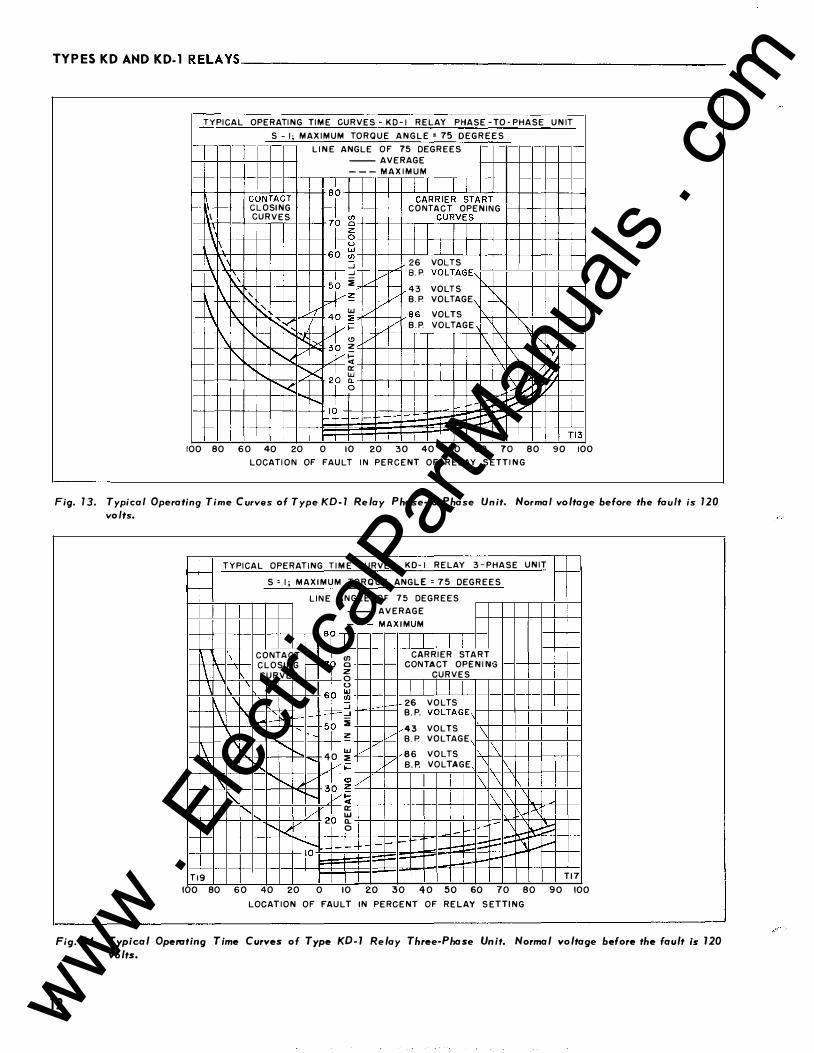
TYPICAL OPERATING TIME CURVES- KD-1 RELAY PHASE -TO- PHASE UNIT S - I; MAXIMUM TORQUE ANGLE = 75 DEGREES
LINE ANGLE OF 75 DEGREES --AVERAGE
---MAXIMUM
�-+--+-+-L.....l:---'--c-+-+-+ 86 +-t-f.,._-t-..LI:-:":-::1--=-���+-+-+-+-+-+-1 CONTACT I CARRIER START 1--li\--1--+-l G LOSING 1--+---t--+-+-+-+-+-l C 0 NTA C T OPENING 1-i-t--+-+--+---l I CURVES 7� �0,_,_+-+-r-� CrU� R�V�E�S.-,-+-r-�-1�� \' I 1- ·+-+-+i-+---+-+-+---+-+--t-+-+-+-+-+---1 '1'- 66 �+-+-��I_L_I�-L�+-+-��-+�-1 \ 1\' I ..J+-+-� 26 VOLTS
\ I ..J �V 8. P VOLTAGE"\ �--����'�+-����50 � / ���-+-+--+-r-1 1\ j_l �� 43 VOLTS I \ ' v +-+--o--1"-/-l B. P. VOLTAGE \t-+"-�-t-+-+-+-� \ ,, -" _I w // ' ' �� 40 71"'-"'+-+--J..- 86 VOLTS '-' i't< \/� / B.P. VOLTAGE 1\
1\ ....._ ���h � v I \ "'-1' r-.r-<v y � 1 \ \ \/, 1--11--t-t��+ . 1-'-, �""< I � I \/�� ....... k 2P g, I ,v:Y./
100 80 60 40 20 0 10 20 30 40 50 60 70 80 90 100 LOCATION OF FAULT IN PERCENT OF RELAY SETTING
Fig. 13, Typical Operating Time Curves of Type KD-1 Relay Phase-to-Phase Unit. Normal voltage before the fault is 120 volts.
T YPICAL OPERATING TIME CURVES KD-1 RELAY 3-PHASE UNIT ,__ 1- r-1-r-1- S = I; MAXIMUM TORQUE ANGLE = 75 DEGREES -1-
LINE ANGLE OF 75 DEGREES --AVERAGE
---MAXIMUM 8� \ CONTACT 7� (/) CARRIER START
\ \ CLOSING - 0 CONTACT OPENING CURVES I z CURVES 0 \ '
6h 0 tJ.J \ "\ ·r (/) 26 VOLTS ::::i -
\ ,_ � ..J B.P. VOLTAGE, f-f'o":" :i ' 43 VOLTS \ " !'.... . i � / B.P. VOLTAGE
l\ �""'--.... I w / 86 VOLTS l\ 40 :::< "" ....... Yi= // B.P. VOLTAGE \ 1\ "'r...... v 3� � / \ \ "" !"-- y� \ 1\ \
....... v 2� � l\-- -\ r--. ..<_ 0 -- . -- \ � 8::: "r-..... -- - f-'"" ..... �
10 ---1--1--
Tl9 Tl7 100 80 60 40 20 0 10 20 30 40 50 60 70 80 90 100
LOCATION OF FAULT IN PERCENT' OF RELAY SETTING
Fig. 14. Typic-al Operating Time Curves of Type KD-1 Relay Th ree-Phase Unit. Normal voltage before the fault is 120 volts.
1 2 www . El
ectric
alPar
tMan
uals
. com
TYPES KD AND KD-1 RELAYS, _________________________ I._L _. 4_1_-4_91_H
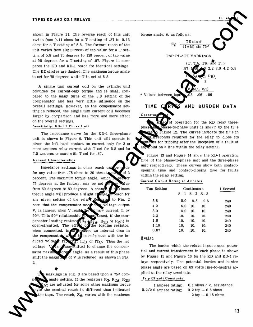
shown in Figure 1 1. The reverse reach of this unit varies from 0 . 1 1 ohms for a T setting of . 87 to 0.13 ohms for a T setting of 5.8. The forward reach of the unit varies from 102 percent of tap value for a T setting of 5. 8 and 75 degrees to 120 percent of tap value at 95 degrees for a T setting of . 87. Figure 1 1 compares the KD and KD-1 reach for identical settings. The KD circles are dashed. The maximum torque angle is set for 75 degrees while T is set at 5.8.
A single turn current coil on the cylinder unit provides for current-only torque and is small compared to the many turns of the 5 .8 setting of the compensator and has very little influence on the overall settings. However, as the compensator setting is reduced, the single turn current coil becomes larger by comparison and has more and more effect on the overall settings. Sensitivity: K D-1 3 Phase Unit
The impedance curve for the KD-·1 three-phas e unit is shown in Figure 9. This unit will operate to close the left hand contact on current only for 3 or more amperes relay current with T set for 5. 8 and for 7. 5 amperes or more with T set for . 87.
General Characteristics
Impedance settings in ohms reach can be made for any value from . 75 ohms to 20 ohms in steps of 3 percent. The maximum torque angl e, which is set for 75 degrees at the factory , may be set for any value from 60 degrees to 80 degrees. A change in maximum torque angl e will produce a slight change in reach for any given setting of the rel ay. Referring to Fig. 2
note that the compensator secondary voltage output
V, is largest when V leads the primary current, I, by 90 °. This 90 o relationship is approached, if the compensator loading resistor (R3, R2A, R2B or R2c ) is open-circuited. The effect of the loading resistor, when connected, is to produce an internal drop in the compensator, which is out-of-phase with the induced voltage, IT, IT A• ITB or ITc: Thus the net voltage , V, is phase-shifted to change the compen
sator maximum torque angle. As a result of this phase shift the magnitude of V is reduced, as shown in Fig. 2.
Tap markings in Fig. 3 are based upon a 750 compensator angle setting. If the resistors R3, RzA• R2B and R 2c are adjusted for some other maximum torque angle the nominal reach is different than indicated by the taps. The reach, ze. varies with the maximum
torque angle, e. as follows:
Z = TS sine e ( 1 ± M) sin 75°
TAP PLATE MARKINGS
(T, TA, TB, and Tc) .87 1 . 16 1 .6 2. 2 3.0 4. 2 5 .8
(S, SA, Sc, RB)
1 2 3
(M, MA, Me)
±Values between taps .03 .06 .06
TIME CURVES AND BURDEN DATA Operating Time
The speed of operation for the KD relay threephase and phase-to-phase units is sho¥.'n by the time curves in Figure 12. The curves indicate the time in in milliseconds required for the relay to close its contacts for tripping after the inception of a fault at any point on a line within the relay setting.
Figure 13 and Figure 14 show the KD-1 operating time of the phase-to-phase unit and the three-phase unit respectively. These curves show both contactopening time and contact-closing time for faults within the relay setting. Current Circuit Rating in Amperes
Tap Setting Continuou s 1 Second s= 1 s= 2 S=3
5.8 5.0 8. 5 9.5 240 4.2 6.0 10. 10. 240 3.0 8.0 10. 10. 240 2.2 10. 10. 10. 240 1 . 6 10. 10. 10. 240 1 . 16 10. 10. 10. 240 0 .87 10 . 10. 10. 240
Burden
The burden which the relays impose upon potential and current transformers in each phase is shown by Figure 15 and Figure 16 for the KD and KD- 1 relays respectively. The potential burden and burden phase angle are based on 69 volts l ine-to-neutral applied to the relay terminals.
Trip Circuit Constants
1 amp ere rating: 0 . 2/2. 0 ampere rating:
0. 1 ohms d. c. resistance 0. 2 tap - 6 .5 ohms
2 tap - 0 . 15 ohms
13 www . El
ectric
alPar
tMan
uals
. com

TYPESKDANDKD-1 RELAYS-------------------------------------------------
14
4
3
2
0 -.1!5
.09
KD RELAY
VOLTAGE BURDEN - S • I
-.03 0 .03 "M" SETTING
KD RELAY
VOLTAGE BURDEN -·s=3
i 1
L 4 I
.09
•·
.15
z lLI 0 1>:
"M" SETTING
KD RELAY
CURRENT BURDEN CURV ES
POTENTIAL CIRCUIT 69 VL-N S = I THREE PHASE CURRENT • 5/-75• AMPERES ��!jl
-- PHASE I --- PHASE 2 OR PHASE 3
PHASE 3 (-32") U: � J+ rf liil
-.09
PHASE 2 (25°) ,I£; ., r•. HH+++m
H �
PHASE I (51°)
rrrtt rt JJ)t tF n e+
-.03 0 .03 liM II SETTING
w 1;+
'
i
.09 .15 "T" TAP SETTING
Fig. 15. Type KD Relay Burden Data.
www . El
ectric
alPar
tMan
uals
. com

TYPES KD AND KD-1 RELAYS-------------------------' -·L _. _41_-4_9 _1H_
"'
KO·I RELAY
VOLTAGE BURDEN � S • 3 5 AMPS �
--T = 5.9
� 3Hf��rn�,--,��TH��KTK+H+H+� UJ CL ::E C( I � 2H+����+H�+H�����P+H+H+rrH >
"M" SETT ING
!5
4
::l 3
0 -.15
KO·I RELAY VOLTAGE BURDEN - S • 2
15 AMPS�
--T•I5.8
---T • 0.87
f:j:j:jj "L" ABOVE "R"
PHASE 3 (21°):=
PHASE 2 ( 32°)
PHASE I (30°)
-.09 -.03 0 .03
"M" SETTING .09 .15
141+-f::Hw-Lumi!r::m:lTTT ''::Btl rrnmUE*E:rn:l:m:1UE:Uilll1lffi +-'-$ H- +++++++++++++-t+++++ I> -1-+ttt t++-+1 t±l\!+++p t-H-_J++t+-+1
z UJ c a:: :::1
12
9
Ill 6
4
2
0
KO·I REL AY IT i J_j_
�tfi{l CURREN T BURDEN CURVES POTENTIAL CIRCUIT 120 VL·L S • I
THREE PHASE CURRENT= 5/7!5" AMPERES 1.!:...,.1m>n -- PHASE I m=mmm:f:J --- PHASE 2 OR PHASE 3
VOLT- AMPERES H-\:1=Jf:t\t �:J::ti H+tt N
.87 1.16 1.6
· VARS
Htfl:tJ WAT T S
2.2 3.0 "T" TAP SETTING
4.2 !5.8
Fig. 16. Type KD-1 Relay Burden Data.
1 5 www . El
ectric
alPar
tMan
uals
. com

TYPESKDANDKD-lRELAYS ________________________________________________ __
SETTING CALCULATIONS Relay reach i s set on the tap plate shown in Fig. 3.
The tap markings are:
T, TA, TB and Tc
.87 1.16 1. 6 2. 2 3 .0 4. 2 5 .8
S , SA, RB and Sc
1 2 3
M, MA, Me
. 03 .06 .06
(Values between taps)
Maximum torque angle is set for 75° ( current lagging voltage) in the factory. This adjustment need not be disturbed for line angles of 650 or higher. For line angles below 650, set for a 600 maximum torque angle, by adjusting R3 , R2A' R2B and R2c. Set zone 1 reach to be 90% of the line (85% for line angles of less than 500),
Calculations for setting the KD and KD- 1 relays are straightforward and apply familiar principles. Assume a desired balance point which is 90 percent of the total length of line. The general formula for setting the ohms reach of the relays is:
Z() = Z (Sin ()) ---- - Zpri ( Sin 750)
-0. 9 Rc
Rv
The terms used in this formula are defined as follows:
Zg = the desired ohmic reach of the relay in
secondary ohms.
Z 1 �s
M = the tap plate setting.
T = compensator tap value
S = Auto-transformer primary tap value
() = Maximum torque angle setting of the relay.
(For a factory setting of 750 then :.n () 0
= 1. ) lll 75
M =.Auto-transformer secondary tap value. ( This is a P er Unit value and is determined by by the sum of the values between the "L " and the "R" leads. The sign is positive when "L " i s above "R" and acts to Lower the Z setting. The sign is negative when "R" is abbve "L " and acts to raise the Z setting),
Zpri = ohms per phase of the total line section
16
0 .9 =the portion of the total line for which the relay is set.
Rc =current transformer ratio
Rv = potential transformer ratio
The following procedure should be followed in order to obtain an optimum setting of the relay.
1. Select the lowest tap S which gives a product ( sin 750)
of 6.9 S greater than Z where Z = Z() . () ( Sin ),
2. Select a value for T that is nearest the value
z s .
3. Determine the value of M that will most nearly TS
make M =z- 1. If the sign is negative, then
the M taps are connected with the R lead above the L lead to Raise the setting.
For example, assume the desired reach, Z() of the relay is 7 ohms at 60 degrees. Then Z = 7 x 1 . 1 1 = 7. 8 ohms.
1. The lowest tap S for 6 .9 S greater than 7.8 is S=2 Sets. SA , RB· and Sc in tap 2.
2. T nearest to 7· 8
= 3 . 9 is 4. 2 ohms 2
Set T, T A• TB and Tc in tap 4.2.
3. M = 78
'4 - 1 = 1 .075 - 1 = . 075 (Use M = . 09)
.8 Set M, M.A and Me for+ . 09.
4. 2 X 2 4. Then Z = ( ) = 7. 7 ohms
1 +. 09
Sin () . 5. Z9= Z (
Sin 750) = 6. 9 relay ohms at a maXImum
torque angle setting of 60 degrees which is 98. 6% of the desired value.
6. Set R3. R:M• R2B and R2c for 60° maximum torque angle.
SETTING THE RELAY The KD and KD-1 relays require settings for each
of the four compensators (T, T A• TB, and Tc), each of the three auto-transformers, primaries (S, SA. and
www . El
ectric
alPar
tMan
uals
. com

.... ......
z 0 ;::: u ... a: 0 "' z n: Q. <r ....
r-.. .... ,. +- • !<),.< """" zz 00 NN
ll
STATION BUS PHASE ROTATION I, 2, 3 D.C. TRIP BUS,::.::.::::........:.., �,· r 4tt -1 J l ' I ! ,_ l ;, F., �
POS, �· � n n n "' •
I 2 3
t:cll-u..A..r .r �='-�-_,. ��-v:...v-�4:'· �r".-fYY\-,_£�+F��•-l:�·
• l - I 1 '"·' "·' VI
J � � !2�:42�2 �212 !2�3 �2�3 �2�3 ��
�� DISTANCE
UNITS SAME AS
ZONE 1
c3c
'---v----' (II¢ DISTANCE
UNIT SAME
AS ZONE 1
C3c
�� Z(30) Z(30) \ 3� ,!11!1l DISTANCE UNIT v 3(11 DISTANCE UNIT"-�
ZONE 1 ZONE 2
tt
ZONE 3
(NEUTRAL FORMED AT RELAY)
T3
2 2 52a {. 0 OHM- �8 W.D.C. t-UcE s�a CONHCT WHEN Rr = 750 OHM • 12i W.D.C.
TRIP COIL SUPERVISION 2000 OHM - 2�0 W.D.C. LI�HT DR O.LA.I,C.S.UHIT IS USED.
tt FOR ZOIIE 3 REVERSED TRIPPING DIRECTION
1. REVERSE CONNECTIONS TO TERMINALS 13 AND 12, 15 AND 1�, 17 AMD 16, 19 AMD 18 OF KD·I RELAY
2. EL IMIUTE All GOUEGTIOIS SHOWN WITHIN THE DOTTED SECTION.COUECT T2 C O IUCTS tTERMIULS 9 l 10) AT THE SAME PLACE IN THE CIRCUIT FORMERLY OCCUPIED BY TM COUACTS (TERMINALS 19 l 201.
DEY I CE MUIIIIER CHART
21·1 - ZOME I PIIASE RELAY, TYI'l KD
21·2 - ZOME 2 P��:� ��U.Y1 21·3 - ZONE 3 PHASE UL.A1,
TYPE KD-1 - T I M I NG RELAY,
TYPE TD-2 52 • POWER CIRCU I T BKI.
a • 8KR. AUX. COIITACT TC • BKR. TR I P COIL ALTERNATE CONNECTION {
----�T2T�\J�����------------------------------------�
* Fig. 17. External Schematic of Two Type KD and one KD-1 Relays with Type TD-2 Timing Relay.
289Bl81
-4 -< .., m Cit "" 0 > z 0 "" 9 .... ;::o m r > -< Cit
, . : � 1.. .., :J:
www . El
ectric
alPar
tMan
uals
. com

TYPES KDAND KD-1 RELAYS __________________________________________________ __
S c) and secondaries (M, MA, and Me), and the balancing resistor RB which should be set at the same value as SA and 8(;. All of these settings are made with taps on the tap plate which is located between the operating units. Fig. 3 shows the tap plate.
Compensator (T, T A• Ts , and Tc )
Each set of compensator taps terminate in inserts which are grouped on a socket and form approximately three quarters of a circle around a center insert which is the common connection for all of the tap s. Electrical connections between common insert and tap inserts are made with a link that is held in place with two connector screws, one in the common and one in the tap.
A compensator tap setting is made by loo sening the connector screw in the center. Remove the connector screw in the tap end of the link , swing the link around un,til it is in position over the insert for the desired tap setting, replace the connector screw to bind the link to thi s insert, and retighten the connector screw in the center. Since the link and connector screws carry operating current, be sure that the screws are turned to bind snugly.
Auto-Transformer P rimary ( S , S A, and S c)
P rimary tap connections are made through a single lead for each transformer. The l ead comes out of the tap plate through a small hol e located just below the taps and is held in place on the proper tap by a connector screw, (Figure 3).
An "S" setting is made by removing the connector screw, placing the connector in position over the insert of the desired setting, replacing and tightening the connector screw. The connector should never mak e electrical contact with more than one tap at a time.
Auto-Transformer Secondary ( M , M A, and M e )
Secondary tap connections are made through two leads identified as L and R for each transformer. These leads come out of the tap plate each through a small hole, one on each side of the vertical row of "M " tap inserts. The lead connectors are held in place on the proper tap by connector screws.
Values for which an "M" setting can be made are from - . 15 to + . 15 in step s of . 03. The value of a setting is the sum of t11e numbers that are crossed when going from the R l ead position to the L l ead position The sign of the "M" value is determined by which lead is in the higher position on the tap plate. The
18
sign is positive (+) i f the L lead is higher and negative (-) if the R l ead is higher.
An "M" setting may be made in the fol lowing
manner. Remove the connector screws so that the L
and R leads are free. Determine from the foll owing
table the desired "M" value. Neither lead connector
should make electrical contact with more than one tap
at a time.
Tabulated Settings
275o M L L ead R Lead
0. 87 TS + . 15 Upper .06 0 0 . 89 TS + . 1 2 Upper . 06 .03 0 .92 TS + . 09 Lower .06 0 0 .94 TS + . 06 Upper . 06 Lower .06 0 .97 TS + .03 . 03 0
TS 0 0 0 1 .03 TS - .03 0 .03 1 .06 TS - . 06 Lower .06 Upper .06 1. 1 TS - . 09 0 Lower .06 1. 14 TS - . 12 .03 Upper .06 1. 18 TS - . 15 0 Upper .06
R 8 Settings
RB is a circuit balancing resistor for the phaseto-phase unit. The RB tap setting should I:Je the same as SA and Sc settings.
Line Ang l e Adj ustment
Maximum torque angle is set for 75° (current l agging voltage) in the factory. This adjustment need not be disturbed for line angl es of 65° or higher. For line angles below 65o , set for a 60° maximum torque angl e by adjusting the comp ensator loading resistors R 3, R 2A· R 2B and R 2c· Refer to repair calibration p arts I (C) and II (B) , when a change in maximum torque angle is desired.
I n d i cating Contactor Sw i t ch ( I C S )
No setting is required for relays with a 1. 0 ampere unit. For relays with a 0. 2/2.0 ampere unit, connect the lead located in front of the tap block to the desired setting by means of the connecting screw. When the relay energizes a 1 25- or 250-volt d-e type WL relay switch, or equivalent, use the 0. 2 ampere tap ; for 48-volt d-e applications set the tmit in a tap 2 and use a Typ e WL relay with a Stt304C209G0 1 coil , or equivalent.
www . El
ectric
alPar
tMan
uals
. com

-"oQ
STAT I O N B U S" P H A S E RQTAT I O N 1 , Z , 3 ZO'-!E. 3 � T I MER. 'COt-JtR.OL � � l t ; I 1 � I 1 � i
POS D. C TR.I P 5 U � ' .,-
2 Q t Ill ol " , 7 0. "-iii f-
� +- ., "' -' .. .. 2 2 0 0 N N
l l
I z. �
ZONE I ZO>J[ Z. ZONE 3
- _ _ _ I
� � � C' l - 1 Z l - 1 2 1 - Z.. Z l - l 2 1 - 3 Z l - 3
SAME A � ZOI-JE I EXCEP<" I
X- REACTOR. I IS NOT USED I I li N �
I I 1 C 3 1\ , R M I I C t i'.C U I T R)I I 1 1 S 1\ PARI\LLFL, 1 COM B I N IITIONj
I
R T
l. l - � �
L _ _ _ _ _ _ j U 5 E �2. <>- CONl"ACT W >< � N l" R. I P C O I L 'S U P E R.V 1 5 1 0 N
ZON e: 3 ZONE Z. Z O N E I
L I C, HT OR 0 . ?. 1\MP I . C . S. UN IT I S U S E D RES I STANC E VA LUES I N OHM� 4 8 V D C. l 1 <05 V. D.C. l250 V. D. C .
350 I z soo I � s o o 150 I z. o o o 7'!>0 I z.ooo
T)( zt T.o< Z3
II e
� TA ""IT � TA !Z"" � TA � � � �----., D I! V i C E N U MBER CHA�T
-t- FOR. ZO>JE 3 REVE R5E.D T R I P P IN(, DIRECT I ON , R.EVE.R.5E COWJECT I O I-J 5 l" O l" ER..M ' S 1 3 if 1 2. , 1 5 tl: 14 , 1 7 ( t i0 , 1 8 ! 1 � 0 F K-D - 1 R E LAY
z .
DE V I CE RE LAY
KO K-D
D E V I G !':
KD - 1 I � l ro-4 TIMINc,l::-:--.,---.,.---::--::-:-c-c POW E R CKT. 5K:C . BKR. A U X . C.CIJTACT BKR. Tii.IP CC I L
290B326
Fig. 18 External Schematic o f Two Type K D and O n e KD- 1 Relay with Type TD-4 Timing Relay.
---4 -< ., m (I' "' 0 >z 0 "' 0 I
:::0 m r-� (I'
:-: !; � � :1:
www . El
ectric
alPar
tMan
uals
. com
TYPES KDANDKD- 1 RELAYS----------------------------------------------------
20
j
STATION BUS
r-+.-+.-_,1•·
I 2 3
AUTO TRANS BANK
PHASE ROTATION I , 2, 3
'------v------' STD. POTENTIAL CONN.
I 2 3
T FOR ZONE 3 REVERSED TR I PP I NG D I RECT I ON :
1 . REVERSE CONNECTIONS T O TERM ' S 1 3 ' 1 2 ,
1 5 ' 1 �, 17 ' I&, 1 9 ' 1 8 , OF KD-1 RELAY
290B235
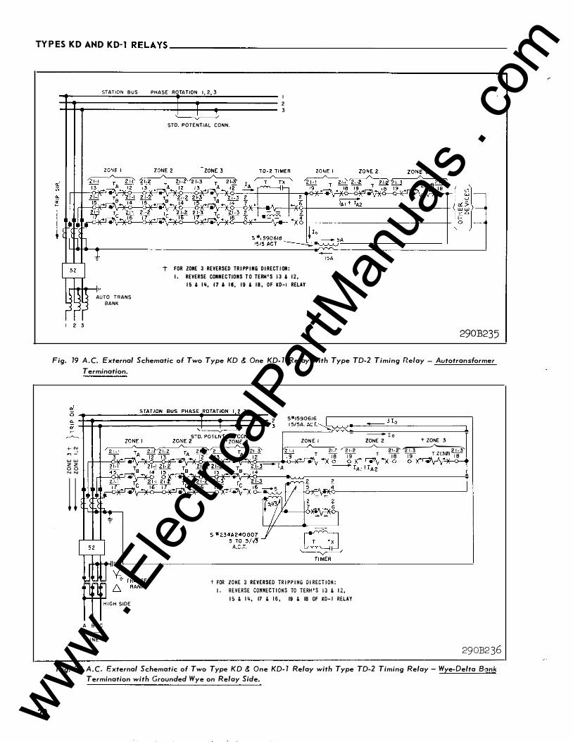
Fig. 19 A . C. External Schematic of Two Type KD & One KD- 1 Relay with Type TD-2 Timing Relay - Autotransformer
Termination.
+ N .., _: "' "' z z 0 0 N N
l l
A 8 C '---v---' L I N E
H I G H SIDE
s•I590616 1 5/5A. ACT.�, A A , ..... -..!!:==-3_1_::oc._ _______ �
ZON E I
T
- r o ZONE 2 i" ZONE 3
21-1 � � J8 19 T 18 19 T Z(3i11) 18 \r*<��P<�,��--��,�,��--���� �\r�o-�r*�
t FOR ZONE 3 REVERSED TR I PP I NG D I RECT I ON : I . REVERSE CONNECT I ONS TO TERM ' S 1 3 & 1 2,
l o & 1 �, 17 & 1 6 , 19 & 18 OF KD- 1 RELAY
290B2 36 Fig. 20 A . C. External Schematic of Two Type KD & One KD- 1 Relay with Type TD-2 Timing Relay - Wye-Delta Bank
Termination with Grounded Wye on Relay Side.
www . El
ectric
alPar
tMan
uals
. com

TYPESKDAND KD-1 RELAYS������������������������I _. L_. _41_-4_9 _1H_
�� STD POTE N T I A L CON N .
w w z z 0 0
1 l S � 234A 240 G07
5 T 0 5/.J3 A . C .T.
� � T I ME R
flflfL1,� j- . FOR ZONE 3 REVERSED TR I PP I NG D I RECT ION:
I l "t . , T RANSF. A 8 C BANK '---. --
I . REVERSE CONNECT I ONS TO TERM ' S 13 & 1 2 , 1 5 & I ij,
1 7 & 1 6 , 18 & 1 9 OF KD- 1 RELAY
L I N E 290B237
Fig. 21 A.C. External Schematic of Two Type KD & One KD- 1 Relay with Type TD-2 Timing Relay - Wye-Delta Bank Termination with Delta on Relay Side.
INSTALLATION The relays should be mounted on switchboard
panels or their equivalent in a location free from dirt, moisture, excessive vibration and heat. Mount the relay vertically be means of the mounting stud for the type FT proj ection case or by means of the four mounting holes on the flange for the semi-flush type FT case. Either the stud or the mounting screws may be utilized for grounding the relay. The electrical connections may be made directly to the terminals by means of screws for steel p an el mounting or to the terminal stud furnished with the relay for thick panel mounting. The terminal stud may be easily removed or inserted by locking two nuts on the stud and then turning the proper nut with a wrench.
For detail information on the FT case refer to IL 4 1-076.
EXTERNAL CONNECTIONS
Fig. 17 shows the connections for 3 zone pro
tection utilizing the TD-2 timer. Fig. 18 is similar to
Fig. 17 except that the TD-4 timer is used instead of
the TD-2. Fig. 18 does not show the use of the 5/5 ·
auxiliary current transformer so that the CT neutral
may be formed elsewhere; however, this connection
is equally applicable whether the TD-2 or TD-4 timer
is employed.
A-C connections for additional applications are shown in Figs. 19, 20, 21 , 22 and 23. Three of these , Figs. 19, 20 and 2 1 apply when the transmission line is terminated in a power transformer, and when low side voltage and current are used to en ergize the relays. In calculating the reach settings, the bank impedance must be added to the line impedance.
For the case of a wye-delta bank (Figs. 20 and 21) the voltages and currents are phase-shifted by 30 o; however, this fact should be ignored, as the KD and KD- 1 relays are not affected by this phase shift.
Use the connections of Fig. 22 when the Ze is less than 0. 75 ohms. The 2 to 1 or 3 to 1 auxiliary current transformers reduce the relay current. In ef-
2 1 www . El
ectric
alPar
tMan
uals
. com

TY PES K D AN D K D- 1 R E LAY S ________________________________________________ __
z 2 .... u UJ cr o <0 z 0: � a:: .... �
f- N ,.. ...: UJ UJ z z 0 0 N N
u
-t - FOR ZONE 3 REHRSED TR I P P I NG D I RECT I ON :
I . REVERSE CONNECT I ONS TO TERM ' S 1 3 l 1 2, 1 5 l 1 �, 1 7 l 1 6 , 1 8 l 19 OF KD-1 RELAY
t � - 3 - 51 1 5906 1 6 A . C . T ' S 1 5 TO 5 OR
3 - 51 1 629905 A . C . T ' S 10 TO 5
Z O N E 2 Z O N E 3 T I M E R �� r------� ZON E 3 �
Z O N E 2 � w TA � w TA zp T T X
n-�---.�---0��
- OPTIONAL Z2 LOCATION I F R E Q U I R E D
I 2 3 290B238
Fig. 2 2 A. C . External Schematic o f Two Type KD & One KD- 1 Relay with Type TD-2 Timing Relay - for Ohmic Settings
Below 0. 75 Ohms.
22
T R I P DIRECTION
fTl V I V2 V3
2 1
7 2 1
• 2 1
9
� � f- DI STANCE U N I T 30i DISTANCE UNIT
A
c >- ·
DEVICE lUt4BERS 2 - TYPE TD-2 REL.AY
21 - TY'f KD-1 RELAY 81Q - TYPE WL RELAY SWITCH
290B239
Fig. 23 External Schematic of Type KD- 1 Relay with Type TD-2 Timing Relay for Generator Backup Protection.
www . El
ectric
alPar
tMan
uals
. com

TYPES KD AND KD- 1 RELAYS _______________________ __:..:.I·::.:L ·:...4:..::..1 ·....:.49.:...;l..:..:...H
feet, the m ain current transformer ratio is increased by a factor of two or three. Using the 2 to 1 ratio, the relay minimum reach setting is 0.375 ohms; with the 3 to 1 ratio the minimum setting is 0. 25 ohms.
Fig. 23 shows a KD- 1 and TD- 2 relay connected for generator back-up protection.
Figs. 19 through 23 show the TD-2 relay; however, the TD-4 is equally applicable. In the case of Figs. �. 2 1 and 23 the two S#234A240G07 auxiliary CT 1s are not required if the TD-4 is used.
S W I TC H B O A R D T E S T I N G W I T H K D A N D K D - 1 R E L A Y S
Immediately prior to placing the relays in service, the external wiring can be checked by manipulating the current and voltage applied to the relay. If such a check is desired, refer to Appendix I for the procedure.
R E C E I V I N G AC C E P T A N C E
KD and KD- 1 relays have a very small number of moving parts and m echanical devices which might become inoperative. Acceptance tests in general consist of:
1. A visual inspection to make sure there are no loose connections, broken resistors, or broken resistor wires.
2. An electrical test to make certain that the relay measures the balance point impedance accurately.
Distance Units
Check the electrical response of the relay by
using the test connections shown in Figure 24 . Set T, T A TB, & Tc for 5 . 8 ; S, SA, Sc , & RB for 1 ;
*M, MA, & Me for + 0. 15 .
A. Use connections for Test No. 1 and adjust the voltages V 1F2F and V 2F3F for 30 volts each.
B. The current required to make the contacts close for the three-phase (bottom) unit should be between 3.44 and 3 .6 amperes at the maximum-torque angle of 75 ° current lag. (Set phase shifter for 105 ° lag in Fig. 24)
c. Use connection for Test No. 5.
D . Adjust the voltage between PH. 1 and lF and
between PH. 2 and 2F for 45 volts each so that the resultant voltage V lF2F equals 30 volts. ( 120-45V-45V = 30V)
E. The current required to make the contacts close for the phase-to-phase (top unit should
* be between 2. 95 and 3 . 1 4 amperes at an angle of 75o current lag.
F. Repeat E while using connections for Test No. 6 and Test No. 7. The difference in values of current that make the contacts close for each of the three test connections should not be greater than 3% of the smallest value.
If the electrical response is outside the liiTlits a more complete series of test outlined in the section titled "Calibration " may be performed to determine which component is faulty or out of calibration.
Indicating Contactor Switch ( ICS)
Close the main relay contacts and pass sufficient d-e current through the trip circuit to close the contacts of the ICS. This value of current should be not less than 1 .0 ampere nor greater than 1 . 2 amperes for the 1 ampere ICS. The current should not be greater than the particular ICS tap setting being used for the 0. 2- 2.0 ampere ICS. The operation indicator target should drop .freely.
The contact gap should be approximately 0. 047" for the 0. 2/2.0 ampere unit and 0 .070" for the 1 . 0 ampere unit between the bridging moving contact and the adjustable stationary contacts. The bridging moving contact should touch both stationary contacts simultaneously.
R O U T I N E M A I N T E N A N C E
The relays should be inspected periodi cally, at such time intervals as may be dictated by experience, to insure that the relays have retained their calibration and are in proper operating condition.
All contacts should be cleaned periodically. A contact burnisher # 182A836HO 1 is recommended for this purpose. The use of abrasive material for cleaning contacts is not recommended because of the danger of embedding small particles in the face of the soft silver and thus impairing the contact.
Distance Units
C AU T I O N : Before making "hi-pot" tests, j umper all contacts together to avoid destroying arc-suppressor capacitors.
23 www . El
ectric
alPar
tMan
uals
. com

TYPESKDANDKD-lRELAYS ________________________________________________ __
Use connections for tests 1, 5 , 6 & 7 of Fig. 24 to check the reach of the relay , or use a K-Dar Test unit for this purpose. When using test 1 of Fig. 24 the phas e angle meter mu st be set for 30 ° more than the maximum torque angle. Note that the impedance mea-
VL-L sured by the 3-phase unit in test 1 is ZR = J3 I L where VL-L is the phase-to-phase voltage and I L is the phase current; similarly, in test s 5 , 6 & 7 of Fig.
VL-L 24 the phase-to-phase unit measures Z R = ---
2IL
Indicat ing Contactor Swi tch ( ICS)
Close the m ain relay contacts and pass sufficient d-e current through the trip circuit to close the contacts of the ICS. This value of current should be not less than 1 .0 ampere nor greater than 1. 2 amperes for the 1 ampere ICS. The current should not be greater than the particular ICS tap setting being used for the 0. 2-2. 0 ampere ICS. The operation indicator target should drop freely.
R E P A I R C A L I B R A T I O N
Use the following procedure for calibrating the relay if the relay has been taken apart for repairs or the adjustments disturbed.
Connect the relay for testing as shown in Figure 24. The four-pole-double-throw switch shown in the test circuit selects the type of voltage condition , for a phase-to-phase or a three-phase fault, that will be ap plied to the relay voltage terminals. The rotary
switch switches the fault voltage to various terminals and thereby simulates any combination of vhase-tophase faults without the tester having to change connections or readjust the phase shifter and variable auto-transformers.
For best results in checking calibration, the relay should be allowed to warm up for approximately one hour at rated voltage. However, a cold relay will probably check to within two p ercent of the warm relay.
Tripping Units
With the stationary contacts open so that the moving contact cannot touch , set the moving contact spring adjuster so that the contact floats freely in the gap. Make sure that there is no friction which prevents free movement of the cylinder and contact arm.
24
The upper pin bearing should be screwed down until there is approximately . 0 25 inch (one complete turn of the. screw) between it and the top of the shaft bearing. The upper pin bearing should then be securely locked in position with the lock nut. The lower bearing position is fixed and cannot be adjusted.
Au totransformer Check
Auto-transformers may be checked for turns ratio and polarity by using the No. 1 test connections of Figure 24, and the procedure outlined below.
Set S, SA· and Sc on tap number 3. Set the "R" leads of M, MA, and Me all on 0 .0 and disconnect all the ' 'L ' ' leads. Adjust the voltages V 1F2F and
V 2F3F for 90 volts. Measure the voltage from terminal 8 to the ttl tap of S and SA- It should be 30 volts. From 8 to the #2 tap of S and SA should be 60 volts. The voltage should read 30 volts from 8 to Sc = 1 and 60 volts from 8 to Sc = 2.
Set S, SA, and Sc on 1 and adjust v1F2F and
V 2F3F for 100 volts. Measure the voltage drop from terminal 8 to each of the M and the M A tap s. This voltage should be equal to 100 ( 1 + the sum of values between R and the tap being measured). Example: 100 ( 1 + .03 + . 06) = 109 volts.
Check the taps of Me in the same manner. Transformers that have an output different from nominal by more than 1 .0 volt probably have been damaged and should be replaced.
D i stan c e U n i t C a l i b ra t i o n Check to see that the taps on front of the tap
block are set as follows:
T, T A- TB, and Tc set on 5. 8
s, SA, RB, and Sc set on 1
"R" for M, MA, and Me set on 0 .0
" L " for M, MA , and Me set in the top po sition ( . 03 + .06 + . 06 = . 15 between L & R).
I. Three-Phase Unit
A. Reactor X (KD relay) or Resistor RM (KD- 1 relay)
The procedure outlined below will assure a proper adjustment of the reactor. The reactor is adjusted to make the impedance angle of its own circuit equal to the impedance angle of the compensator secondary 's circuit.
www . El
ectric
alPar
tMan
uals
. com

TYP ES K D AN D KD-1 R ELAYS _______________________ ____ 1 ·_L_. _41_-4_9_1 H_
1. Connect the circuits of terminals 7 and 9 in parallel by disconnecting 1F from Brush No. 1 and connecting 1F to 3F in Figure 24.
2. Adjust Brush No. 2 for 105 volts between terminals 8 and 9. Voltage is zero between 7 and 9 because of the parallel connection. ( 105 volts is sufficiently high to detect small unbalancing and not high enough to cause saturation of the reactor. )
3. Adjust X or RM for zero contact closing torque and a minimum of opening torque. Excessive opening torque tends to mak e the relay under reach at low voltages.
4. The core adjustment should be check ed after any adjustment of X.
B. Core adjustment (KD relay only).
The lower cylinder unit of the KD relay contains an adjustable core which is set at the factory to give a biasing action that prevents contact closing on current-only. This adjustment can be check ed by passing current in terminal 19 and out terminal 18. (The K D- 1 relay is purposely biased to produced current-only contact-closing torque and will open its right hand contact at a current value of 3 amp eres when T= 5. 8).
1. Open the selector switch to a neutral position and short circuit terminals 7, 8 and 9 or 1 F 2F, and 3F in Figure 24.
2. Pass 5 amp eres in the current circuit and increase the current to 60 amp eres in convenient steps. Adjust the core so that no contact closing torque is produced for all values of current. Do not bias the unit more than is necessary because exc essive op ening torqu e will tend to mak e the relay under reach at low voltages.
3. The Reactor X adjustment should be checked after any change in core adjustment.
C. l\1aximufl'l torque angle adjustment.
1. Use the No. 1 test switch positions and lead connections as tabulated in Figure 24.
2. Adjust the voltages V 1F2F and V 2F3F for 50 volts with Brush No. 1 and Brush No. 2 respectively .
3. Adjust the current to 6 amperes and rotate the
phase shifter to find the two angl es, e1 and e2.
at which the bottom unit contacts just close.
The maximum torque angle e for the three-
i1t + e2 phase unit then is (
2 - 30) degrees.
This angle should be between 73 ° and 76 o for a nominal 75 ° adjustment. (Phase-shifter reading of 103 ° to 106 ° in Fig. 24)
4. A smaller angle may be obtained by reducing R 3 , in which case the test current should be
6 sin 75° equal to . 0 amper es. The angle may be
Sln
increased by increasing R3
.
D. Contact Adjustment.
KD Relay: With moving-contact arm against righthand backstop, screw the stationary contact in until it just touches the moving contact. (Check for contact by using an indicator lamp. ) Then back the l efthand contact out two-thirds (2/ 3) of one turn to give 0.020-inch gap between contacts.
K D- 1 Relay: With moving contact-arm against right hand side of bridge, screw the right-hand contact in to just touch the moving contact and then continue for one more complete turn. Adjust left-hand contact as described above, except back off one and one-half ( 1- 1/2) turns to give approximately 0.047-inch gap.
E. Spring Restraint: Reconnect for a three-phase fault, Test No. 1, and set .the phase shifter so that the current lags voltage by the maximum-torque angle. ( 105 ° in Fig. 24) Adjust the spring so that the current required to close the left-hand contact is as follows:
Voltages V 1FZF and V 2F3F = 10 volts
Current to trip K D
Current t o trip K D- 1
= 1 . 27 amperes
= 1. 3 amperes.
II. Phase-to-Phase Unit:
A. Rough Adjustment of RMA and RMc
Set RMA to slightly less than half the adjustable
range so that the adjustable band is nearer the center than the end.
1 . Using connections for test #1 of Figure 24 adjust brush #1 so that V 1F 2F = V73 = 0. Adjust
brush #2 for rated voltage across terminals 8 & 9 . Adj ust RB so that the con tact floats or has a
minimum of torque. This is a rough adjustment for making the impedance angl e of phase 1 to
be equal to impedance angle of phase 2.
25 www . El
ectric
alPar
tMan
uals
. com
TYPES KDANDK�lRELAYS ________________________________________________ _
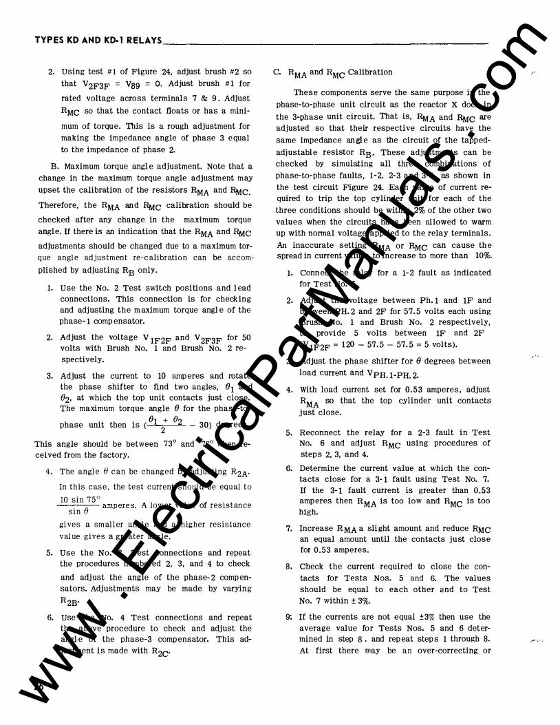
2. Using test # 1 of Figure 24, adjust brush #2 so that V2F3F = V39 = 0. Adjust brush #1 for
rated voltage across terminals 7 & 9 . Adjust RMc so that the contact floats or has a mini-
mum of torque. This is a rough adjustment for making the impedance angle of phase 3 equal to the impedance of phase 2.
B. Maximum torque angl e adjustment. Note that a change in the maximum torque angle adjustment may upset the calibration of the resistors RMA and �C. Therefore, the RMA and �C calibration should be
checked after any change in the maximum torque angle. If there is an indication that the RMA and �C adjustments should be changed due to a maximum torque angle adjustment re-calibration can be accom
plished by adjusting RB only.
1. use the No. 2 Test switch positions and l ead connections. This connection is for checking and adjusting the m aximum torque angl e of the phase- 1 comp ensator.
2. Adjust the voltage V 1FZF and V 2F3F for 50
volts with Brush No. 1 and Brush No. 2 respectively.
3. Adjust the current to 10 amp eres and rotate the phase shifter to find two angles, 01 and Oz, at which the top unit contacts just close. The maximum torque angle 0 for the phase-to-
phase unit then is ( 01
2+ Oz - 30) degrees.
This angle should be between 73° and 76° when received from the factory.
26
4. The angle 0 can be changed by adj usting RzAIn this cas e , the test current should be equal t o
10 sin 7 5 ° . ---- amperes. A low er value of resistance
sin e gi ves a smaller angle and a higher resistance
value gives a greater ang le.
5. Use the No. 3. Test connections and repeat the procedures numbered 2, 3, and 4 to check
and adjust the angle of the phase- 2 comp ensators. Adjustments may be made by varying RzB·
6. use the No. 4 Test connections and repeat the above procedure to check and adjust the angl e of the phase-3 compensator. This adjustment is made with Rzc·
C. RMA and RMc Calibration
These components serve the same purpose in the phase-to-phase unit circuit as the reactor X does in the 3-phase unit circuit. That is, �A and RMc are adjusted so that their respective circuits have the same impedance an gl e as the circuit of the tappedadjustable resistor RB · These adjustments can be checked by simulating all three combinations of phase-to-phase faults, 1-2, 2-3 and 3-1 , as shown in the test circuit Figure 24. Each value of current required to trip the top cylinder unit for each of the three conditions should be within 2% of the other two values when the circuits have been allowed to warm up with normal voltage applied to the relay terminals . An inaccurate setting RMA or RMc can cause the spread in current values to increase to more than 10%.
1. Connect the relay for a 1-2 fault as indicated for Test No. 5.
2. Adjust the voltage between Ph. 1 and 1F and between PH. 2 and 2F for 57. 5 volts each using Brush No. 1 and Brush No. 2 respectively, to provide 5 volts between 1F and 2F (V 1F2F = 120 - 57. 5 - 57. 5 = 5 volts).
3. Adjust the phase shifter for 0 degrees between load current and VPH. 1-PH. 2.
4. With load current set for 0 .53 amperes , adjust RMA so that the top cylinder unit contacts just close.
5. Reconnect the relay for a 2-3 fault in Test No. 6 and adjust RMc using procedures of steps 2, 3, and 4.
6. Determine the current value at which the contacts close for a 3- 1 fault using Test No. 7. If the 3- 1 fault current is greater than 0.53
amperes then RMA is too low and RMc is too high.
7. Increase R MA a slight amount and reduce RMC an equal amount until the contacts just close for 0.53 amperes.
8. Check the current required to close the contacts for Tests Nos. 5 and 6. The values should be equal to each other and to Test No. 7 within ± 3%.
9: If the currents are not equal ±3% then use the average value for Tests Nos. 5 and 6 determined in step 8 . and rep eat step s 1 through 8. At first there may be an over-correcting or
www . El
ectric
alPar
tMan
uals
. com

TYPESKD AND KD -1RELAYS _________________________________________________ I . L_._4_1�_9_1 H_
p endulum action as one balances the RMA and and RMC resistors. However, with a little experience the circuits can be balanced after two or three trials.
D. Spring Restraint.
1. Use Test No. 1 connections except reverse the voltage phase sequence by interchanging the Brush connections so that Brush 1 is connected to 3F and Brush 2 is connected to 1F.
2. Adjust the voltages V 1F2F and V 2F3F for 3. 5 volts each with Brush No. 2 and Brush No. 1 respectively. Position the moving-contact spring adjuster so that the contact just floats and then return the circuit connections to normal with Brush 1 to 1F and Brush 2 to 3F.
E. Contact Adjustment
The procedure for contact adjustment for the phase-to-phase unit is identical to that described in section D for the three-phase unit.
The phase-to-phase unit is now calibrated and shoul d be accurate to within ± 3% of the corrected tap value setting over the range of fault voltages from 5 VL-L to 120 VL-L· The corrected tap value is actual rel ay reach at a given maximum torque angl e 0
. TS sin 0 and 1s equal to Z o = ( 1 ± M) (sin 7fP ) • The rel ay 1s
now calibrated and ready for service.
III. Compensator Check
Accuracy of the mutual impedance Zcof the compensators is set within very close tolerances at the factory and should not change under normal conditions. The mutual impedance of the compensators can be checked with accurate instruments by the procedure outl ined below.
A. Set T, T A' TB, and Tc on the 5 .8 tap.
B. Disconnect the "L" leads of sections M, MA, and Me and the brush leads of R3, R2A• R2B , and R2c· (With resistor loading removed 0 = 90").
C. Connect terminal s 13 to 14, 15 to 16, 17 to 18 and pass 10 amperes a.c. current in terminal 19 and out of terminal 12.
D. Measure the compensator voltage V C with a high resistance voltmeter 5,000 ohm/volt as tabulated below. Refer to Figure 1 for the location of R3, R2A• R2B, and R2c·
Measure Vc From To Fixed Terminal End of
"L" of M R3
"L" of MA R2A
8 R2B
"L"of Mc R2c
Voltmeter Reading
sin 0 -V C = 1.5 I T( sin 750 )
= 90. 1 volts ( 0 = goo)
sin 0 V = I T ( ) C sin 75°
= 60. 1 volts ( 0 = goo)
E. Any compensator that has an output which is 2 volts more or less than the nominal values given above should be replaced.
IV. overall Check
Mter the calibration procedure has been completed, perform the following check.
A. Three-Phase Unit Connect the relay for a three-phase fault, Test
No. 1 of Figure 24, and set the phase shifter so that the phase angle meter indicates 30 .o more than the
maximum torque angl e. The current required to trip the rel ay should be within the limits specified for each of the voltages. Note that for the three-phase unit the
impedance measured by the relay is ZR = VL-L where y'3 IL
VL-L is phase-to-phase fault voltage and IL is phase current.
Volts Amperes (0 = 75 ) tt & t
V lF2F & V2F3F I min Imax
10 - 1.28 KD 1. 3 KD- 1
30 3. 44 3. 6 KD 3. 65 KD- 1
70 7.85 8. 1 Both
t to determine the limits of current when 0 is not equal to 750 multiple the nominal values tabulated
. sin 75° above by the ratw -. -n- · SID u
tt Phase angl e meter set for 0 + 300.
27 www . El
ectric
alPar
tMan
uals
. com

N co
PKASE ROTAT I ON 1 I - 2 I - 3 1
i: • r I I r L---------------------+ 22
PH. I
P H . 2
PM . 3
1·2 FAULT � ;{21 ' 1r CD ® 2F (D
3 - �2 2-3 FAULT �
±
IIATTIIETER OR
PHASE ANCLE IHT£1 +
75°
/ , I F @
(f) 3 k2_,�F @ - - - 2
I 3- 1 FAULT /\ I F@ //\ 2F CD
(!} 3 �,�2
I " 3 f FAULT 1 \ IF (D 31�-620 ®3F
A U E 7 E R
YAR I A�LE AUTO-TRANSFORMER 200 VOLT- AMPERES �
+---' · - · 31 �
4 P. O.T. SWITCH
23
D. C. ---..... ---------t-
IT 15 13 I 2 1 4 :
I ± 1 1 I t I ± 1 1 I I
FAULT TEST
ROTARY SW I TCH
SUBTRACT 30° FROM ThE PHASE-ANuLE-METER READ I NG TO DETERM I NE THE RELAY MAX IMUM TORQUE ANGLE -HEN THE SELECTOR I S I H THE 3 f POS I T ION.
KO OR KD-1 RELAY (fRONT V I E•)
I CO"TACT ,J:.\
: CLOSING ',¥�' . _ I ' I .
I
' ._ _ _ _ _ ,._ _ _ - -
D OTTED C O N N E CT I O NS
FOR K D - 1 R E L AT OML Y FOR KD R E L A Y OILY
TEST SELECTOR FAULT TO CHECK CONNECT FROM/TO 110. TEST OR ADJUST
(zR � �-�\ ) {
( _ V L- L ) {
Z R --2 I L
1 _ _L_
3 14
-� _ _§___ 7
3 • 3 • tl J .
--t:J ...
1-2 R3 23/ 1 3 22121 1-2 R_u 23/13 22/21 2-3 R u 23/ 1 5 ...nm. 3-1 Ru 23/ 17 22/21 -1-2 RN A 23/ 13 22/11 2-3 _1114_c 23/ 1 5 2211 7 3-1 CHECK 23/ 17 . 22/1 3
I
290:8338
Fig. 24 Test Connections for Type KD and KD- 1 Relays.
...... -< ., m Cll � c � z c
I � ? ... ;:10 m r � -< Cll
www . El
ectric
alPar
tMan
uals
. com
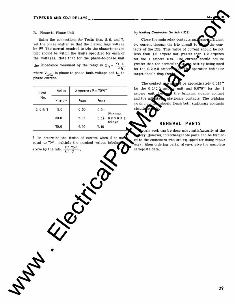
TYPES KD AND KD-1 RELAYS -----------------------.,...--1-- L_. _41_-4_9_1 H
B. Phase-to-Phase Unit
Using the connections for Tests Nos. 5, 6, and 7, set the phase shifter so that the current lags voltage by eo. The current required to trip the phase-to-phase unit should be within the l imits specified for each of the voltages. Note that for the phase-to-phase unit
the impedance measured by the rel ay is ZR = VL-L
2 IL where VL-L is phase-to-phase fault voltage and IL is phase current.
Test Volts Amperes ( () = 750)t
No. V 1F2F I min I max
5, 6 & 7 5.0 0 . 50 0 . 54 For both
30. 0 2. 95 3. 14 KD & KD- 1, rel ays
70. 0 6.90 7. 10
t To determine the limits of current when () is not equal to 75° , multiply the nominal values tabulated
. sin 750 above by the ratw . () Sin
Indicating C ontoctor Switch ( I C S)
Close the main relay contacts and pass-sufficient d-e current through the trip circuit to close the contacts of the ICS. This value of current should be not less than 1.0 ampere nor greater than 1. 2 amperes for the 1 ampere ICS. The current should not be greater than the particular ICS tap setting being used for the 0. 2- 2. 0 ampere ICS. The operation indicator target should drop freely.
The contact gap should be approximately 0.047,. for the 0 . 2/ 2. 0 ampere unit and 0 .070 .. for the 1
ampere unit, between the bridging moving contact and the adj ustable stationary contacts. The bridging moving contact should touch both stationary contacts simul tan eo usly.
R E N E W A L P A R T S
Repair work can b e done most satisfactorily at the factory. However, interchangeable parts can be furnished to the customers who are equipped for doing repair work . When ordering parts, always give the complete nameplate data.
29 www . El
ectric
alPar
tMan
uals
. com
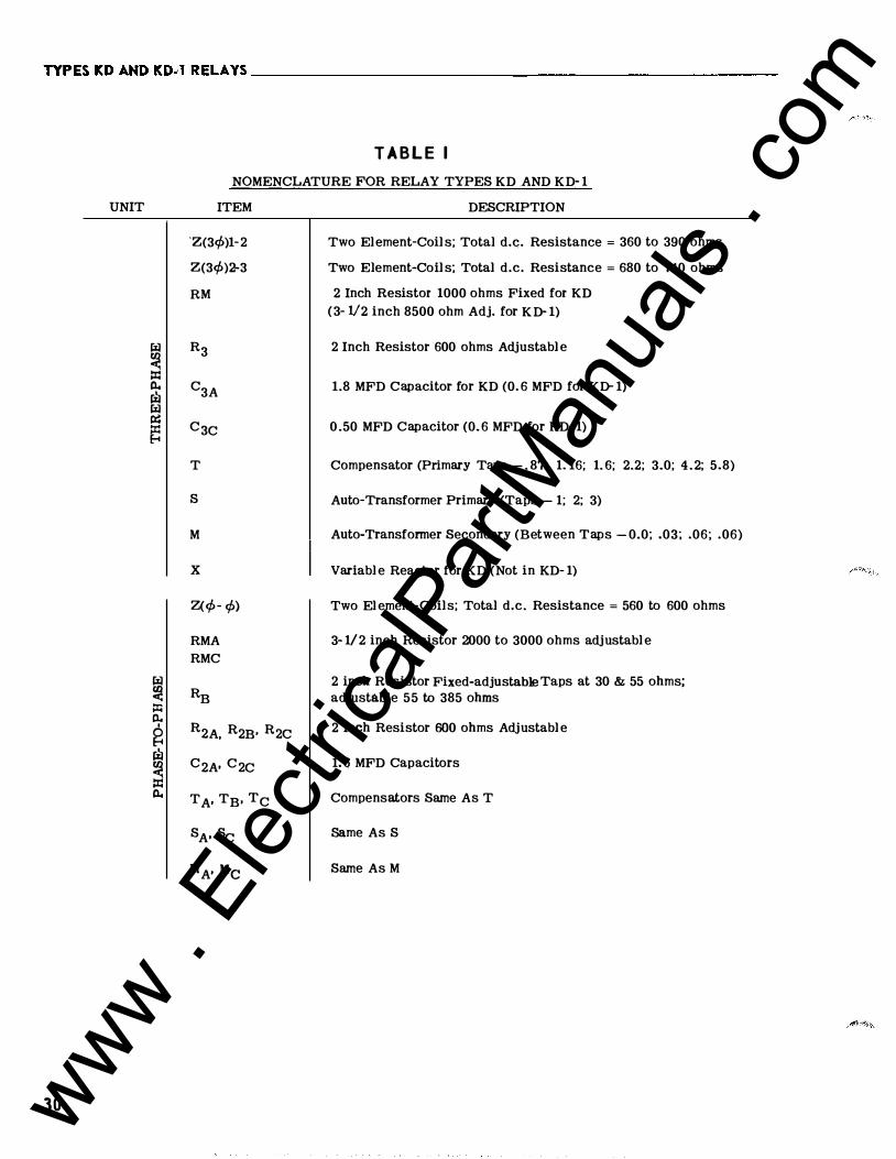
TYPES KDAKDKD·l RELAYS ________________________________________________ __
UNIT
fil � � P.. � fil � � �
fil � ::X:: P..
I
g � � � P..
30
T A B L E I
NOMENCLATURE FOR RELAY TYPES KD .AND KD- 1
ITEM
'Z(3</>)1-2
Z(3</>)2-3
RM
R3
c3A
C3c
T
s
M
X Z(</>- </>)
RMA RMC
RB
R2A, R2B• R2c
c2A· C2c
TA, TB, Tc
SA• Sc
MA' Me
DESCRIPTION
Two Element-Coil s; Total d.c. Resistance = 360 to 390 ohms
Two Element-Coil s; Total d.c. Resistance = 680 to 740 ohms
2 Inch Resistor 1000 ohms Fixed for KD (3- V2 inch 8500 ohm Adj. for KD- 1)
2 Inch Resistor 600 ohms Adjustabl e
1.8 MFD Capacitor for KD (0. 6 MFD for KD- 1)
0 .50 MFD Capacitor (0. 6 MFD for KD- 1)
Compensator (Primary Taps - . 87; 1. 16; 1. 6; 2.2; 3.0; 4 .2; 5.8)
Auto-Transformer Primary (Taps - 1; 2; 3)
Auto-Transformer Secondary (Between Taps - 0.0; .03; .06; .06)
Variabl e Reactor for KD (Not in KD- 1)
Two El ement-Coils; Total d.c. Resistance = 560 to 600 ohms
3- 1/2 inch Resistor 2000 to 3000 ohms adjustabl e
2 inch Resistor Fixed-adjustable Taps at 30 & 55 ohms; adjustable 55 to 385 ohms
2 inch Resistor 600 ohms Adjustabl e
1. 6 MFD Capacitors
Compensators Same As T
Same As S
Same As M
www . El
ectric
alPar
tMan
uals
. com

TY P ESKDANDKD-1 RELAYS ������������-�����������-I . L_. _4 _1 - _�_1 H_
f.- I 9
I "�l r"" i - - � t lllicO (fl i I
- - - + I • A-'t:.
o�ltJ �.f - -
l I -
---
--..4 �1 k- ' I � ��� I � I r.----<;; 8---.; �� PANEL LOCATION SEM I - FLUSH MTG.
PROJECTION MTGr. i'\ �� __---. 1 90-32 sc� EW
5PI1C££S f=n£ --THIN PANEL'S � - J S <;:,CREW I"
(FOR THICK
5PAN EL USE �-IB STUD)
TERMINAL .A-NO MOU NI I NGr DETAILS
NOT £ ; ALL DI M E NS I O NS IN I NCHES.
TERM I NAL
* DIA . 4 H O L-E S F"OR. . 1 9 0 ·32 NITGr. SCRE.W&
-IN co
-I-t ., I
<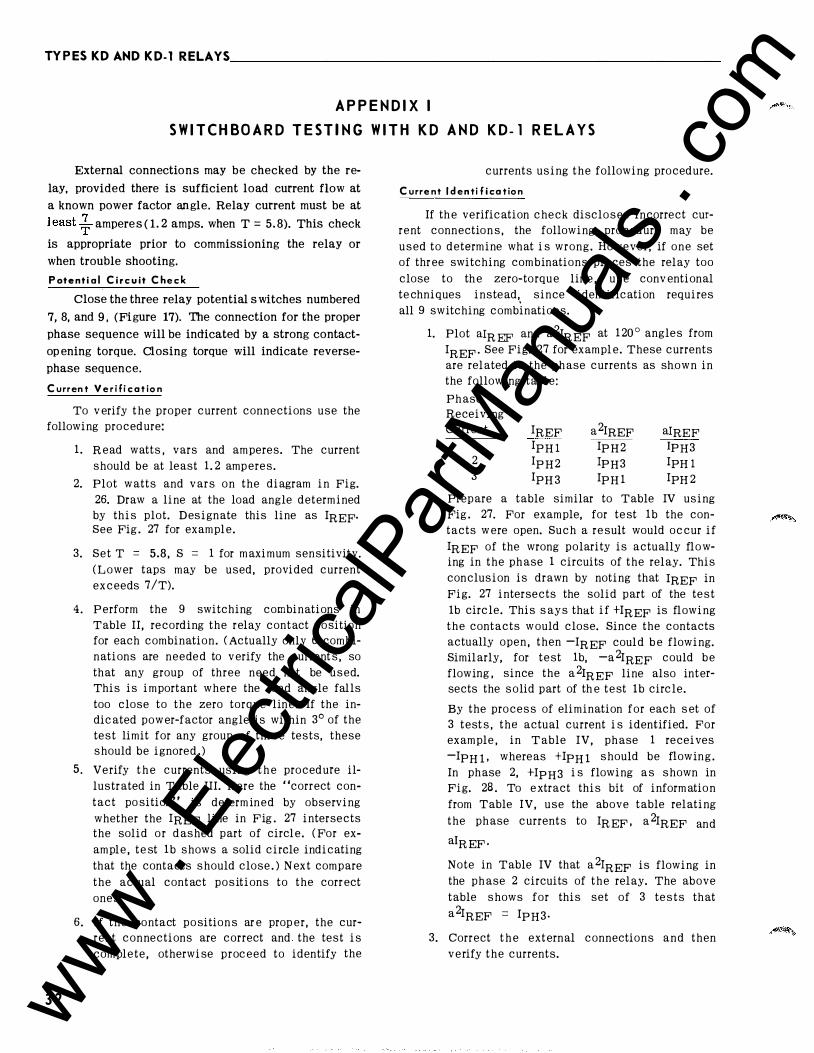
TYPESKDANDKD-1 RELAYS ____________________________________________________ _
A P P E N D I X I
S W I T C H B O A R D T E S T I N G W I T H K D A N D K D - 1 R E L A Y S
External connections may be checked by the relay, provided there is sufficient load current flow at a known power factor angle. Relay current must be at least � amperes ( 1 . 2 amps. when T = 5. 8). This check
is appropriate prior to commissioning the relay or when trouble shooting. Potential Cir c uit Che c k
Close the three relay potential s witches numbered 7, 8, and 9 , (Figure 17). The connection for the proper phase sequence will be indicated by a strong contactop ening torque. Closing torque will indicate reversephase sequence.
Current V e r i f i cation
To v erify the proper current connections use the
following procedure:
3 2
1. R ead watts , vars and amperes. The current
should be at least 1. 2 amp eres.
2. Plot watts and vars on the diagram in Fig.
26. Draw a line at the load angle determined
by this plot. Designate this line as IREF· See Fig . 27 for exampl e.
3. Set T = 5.8, S = 1 for maximum sensitivity.
( L ower taps may be used, provided current
exceeds 7 /T).
4 . P erform the 9 switching combinations in
Table II, recording the relay contact position
for each combination. ( Actually only 6 combi
nations are neede d to v erify the currents, so
that any group of three need not be used.
This is important where the load angle falls
too close to the zero torque line. If the in
dicated pow er-factor angle is within 3° of the
test limit for any group of three tests, these
should be ignored. )
5. Verify the currents using the procedure il
lustrated in Table III. Here the "correct con
tact position" is determined by observing
whether the lREF line in Fig . 27 intersects
the solid or dashed part of circl e. ( For ex
ample, test 1b shows a solid circle indicating
that the contacts should close . ) N ext compare
the actual contact positions to the corr ect
ones.
6. If the contact positions ar e prop er, the cur
rent connections are correct and the test is
complete, otherwise proceed to identify the
currents using the following procedure.
Current Identi fication
If the verification check discloses incorrect cur
rent connections, the following procedure may be
used to determine what is wrong. However, if one set
of thr ee switching combinations places the relay too
close to the zero-torqu e lin e , use conv entional
techniques instead,,
since identification requires
all 9 switching combinations.
1. Plot aiR EF and a 2IREF at 1 20 ° angles from
IREF · See Fig. 27 for exampl e. These currents
are related to the phase currents as sh,own in
the following tabl e:
Phase Receiving
Current IREF a 2IREF aiREF 1 IpH l Ip H 2 1PH3 2 Ip H 2 1PH3 IpH l 3 IpH 3 IpH 1 IpH 2
2. Prepare a table similar to Table IV using
Fig . 27. For example, for test 1b the con
tacts w ere open. Such a result would occur if
IREF of the wrong polarity is actually flo w
ing in the phase 1 circuits of the relay. This
conclusion is drawn by noting that lREF in
Fig. 27 intersects the solid part of the test
1b circle. This says that if +IREF is flowing
the contacts w ould close. Since the contacts
actually open , then -IREF coul d b e flowing.
Similarly, for test 1b, -a 2IREF could b e
flowing , since the a 2rREF line also inter
sects the solid part of th e test 1b circle.
By the process of elimination for each set of
3 tests , the actual current is identified. For
example , in Table IV, phase 1 receives
-IPH 1 · whereas +lPH 1 should be flowing.
In phase 2, +IpH3 is flowing as shown in
Fig. 28 . To e xtract this bit of informatio n
from Table IV, use the above table relating
the phase currents to IR EF · a 2IREF and
a! R EF ·
Note in Table IV that a 2rREF is flowing in
the phase 2 circuits of the relay. The above
table shows for this set of 3 tests that
a 2IREF = IpH3·
3. Correct the ext ernal connections and then
v erify the currents.
www . El
ectric
alPar
tMan
uals
. com

1
2
3
4
5
6
TABLE II SWITCH IN G FO R CURREN T V ERIFIC ATION AND I D ENTIFIC ATION
Po sition of s witches numbered:
Voltage sw.
7 8
Open & j ump s w .
j aw to
9
Clo s e d
Clo s ed
Clo s e d
Open & j ump sw.
j aw to
8
Clo s ed
Closed
Op en & jump sw.
j aw to
7
Closed
Clo s e d
Clo s e d
Op en & j um p sw.
j aw to
9
9
Closed
Current sw. ( b lank indicates
open sw. )
a
1 2 ,
1 3
b C l o s ed
a Clo s ed
1 4 ,
15
16,
17
Closed
18 ,
19
( 3¢)
Clo s ed
Clo s ed
Unit which Pha s e
should b e Receivi n g
Observed Current
¢-¢ & t 3
¢-¢ & 3¢
¢-¢ & 3¢ Clo sed e-if------+-----f-- ---+-----+-- -----+------1
b C l o s e d ¢-¢ & t 2
Open & a Clo sed ¢-¢ & t 2
jump sw. e-lf-----+----+-----+----+------+---� j aw to
b 8
Open & j u m p s w .
j aw t o 7
Clo s e d
C l o s e d
Clo s ed
Clo s ed
Clo se d
Closed
¢-¢ & t 3
Clo s ed ¢-¢ & 3¢ 1
¢-¢ & t 2
¢-¢ & t 3
t Block 3 ¢ Unit Open
tt 3 ¢ unit operation i s based on the relay looking i nto the line. For c arrier applications with
KD- 1 looking i n the reverse direction, the contacts should b e i n the oppo site positions from
tho s e listed in the table .
33 www . El
ectric
alPar
tMan
uals
. com

TYPESKDANDKD-1 RELAYS __________________________________________________ __
TABLE I l l V ERIFIC AT IO N EXAM PL E U SIN G ASSUMED L O ADIN G O F FIG . 27
P H ASE SWITCHIN G
C O RREC T ACTU AL C O NTACT P O SITION
TO B E COMBIN ATION
C O NT ACT IF WIRING E XAM P L E WITH
V ERIFIED POSITION IS CORRECT INCOR RECT WI RIN G
1 b c c 0 1 2a c c 0
4 0 0 c 2b c c c
2 3a c c 0 5 0 0 c 3b c c 0
3 1 a c c 0 6 0 0 0
TABLE I V ID ENTIFICATION EXAM P L E U SIN G ASSUMED L O ADING OF FIG . 27
!REF. EXAMPLE CURRENT & P O L ARITY WHICH CAN
PH A SE SWITCHING O F P RODUCE OBSERV E D CONTACT POSITION
R E CEIVING COMBIN ATI O N C ONT ACT
CURRENT POSITION lREF. a2IREF. alR EF .
1 b 0 G - + 1 2a 0 t + +
4 c + -
2b c + rn -
2 3 a 0 - t + 5 c - -
3b 0 - -
rn 3 1a 0 - + t 6 0 + -
t See Fig. 28 for actual c on nectio ns.
34 www . El
ectric
alPar
tMan
uals
. com

TYPES KDANDKD-1 RELAYS ������������������������-'-· L_. _41_�_9 _1 H_
9�� �(•bl �o7l)? I l b 60° " -..,t ' ' ,- -
2 70,..,
VARS IN
6 Q -& o 75
• 6 • I
�� --- ' ' 0 \ Go· �� /@W - 'fQ _\ � .. 18 0 WATTS
IN 9Qo
-&� 75° � 60°
I >
If � ' r. \ \ * \ -----r---.. l{"tN (il
'l ' 5 f-.g. = 75 ° � �o· f---WAT TS
\a)_ O U T
jt AfrL - ---- - f--/ -� lJ!--v J�t �� (90• \.o 75•
.. 0
' 60•
4 =75°
OUT - IN THE TRIPPING DIRECTION IN - - AGAINST TRIPPING DIRECTION
THE THREE-PHASE UNIT SHOULD RESPOND TO TESTS 1b, 20 AND 4 . DISREGARD THREE-PHASE UNIT ON ALL OTHER TESTS.
#c- POSITIVE DEGREES BASED ON CURRENT LAGGING VOLTAGE (POSITIVE CURRENT • CURRENT FLOWING OUT )
VARS O U T
90 .. SOLID LINE - CONTACT CLOSING TORQUE DASH LINE - CONTACT OPENING TORQUE
FOR -e-Pf ANGLES 3" fROM ZERO TORQUE, THE PRODUCT OF I )( T MUST BE � 7
I = L I N E CURRENT T • TAP "T" SETTING
185A016
X QIREF
\ 9
�� � �� �o
7
1� I lb
69" ' 1 -...,t ' -'� '
� -
270
VARS IN
;q -& o75 '
6 • I
�� --- ' ' :::--- Go• ' '
.g. = 75 • /@� # \ r<� _\ \ � � \ � 90---f--.. 18 0 WATTS
IN 9Qo
-G-= 75° [ -f--- 60)
,_{6 ,\ \ ( � \ K: /' ..........
I -10 jt .e;
v ·�y ?-....d,b I _ ,
WATTS OUT
. 0 I R E
I �� ' � ,/ �o·
� � 90• <>- 75
v -&
� 7t. 60•
, a2 l R E F VARS OUT
90 .. OUT - IN THE TRIPPING DIRECTION IN - - AGAINST TRIPPING DIRECTION
THE THREE-PHASE UNIT SHOULD RESPOND TO TESTS 1b, 20 AND 4 . DISREGARD THREE-PHASE UNIT ON ALL OTHER TESTS.
# - POSITIVE DEGREES BASED ON CURRENT LAGGING VOLTAGE (POSITIVE CURRENT = CURRENT FLOWING OUT )
SOLID LINE - CONTACT CLOSING TORQUE DASH LINE - CONTACT OPENING TORQUE
FOR -&PF ANGLES 3° FROM ZERO TORQUE, THE PRODUCT OF I x T MUST BE � 7 I = LINE CURRENT T = TAP "T" SETTING
PHASE DIAGRAM FOR CIRCUIT VERIFICATION WITH K·DAR RELAYS
Fig. 26 Phase diagram for Current Circuit Verification and Identificat ion
Fig. 27 Phase Diagram Showing Assumed Load Conditions for an Example
I 2 3 POWER FLOW
T
( b ) CASE I CURRENTS
185A060 Fig. 28 Actual Wiring for the Assumed Test Results of
Table I V
35 www . El
ectric
alPar
tMan
uals
. com

W E S T I N G H O U S E E L E C T R I C C O R P O R A T I O N R E LAY- I N STR U M E NT D IVI S I O N N EWAR K, N . J.
Printed in U.S.A. www . El
ectric
alPar
tMan
uals
. com

- ..
' I
I � ..
. -
and l\ :J -
I(> - �-l ·- "' "' •' ..
S upple�ent a�y I� L .
C O�;�PENSATOR DISTA N E
.1. l ! i S supplementary I . L . have l . l-30 ohms re.: >;h .
covers ' spec ial t ype of KD-4 ·- · - ,._
�-. Appl i aation - the c;.:..rr.e as p€. r- I . L . 41..-491 . 4A -� 1 fM' , ·- : · . '#et C onstruct io=1 - tt � sa�e as p r:. r I . L 41·- 491 . 4A , exc ept co�;f;at or are markecr1 . 3 l �· 1 . 74 - 2 • . c d - 3 . 0 5 - 4 . 3 5 - _6 . 1 - 8 . 7 ohr.tS .
Operat ion - t he same a s pt-r I . L 4l- 49 1 . 4A
Chara ct eri st i c s - t he s a rr.El a s .fJer I " L . 41 -49 1 . 1tA , exc ept :
t aps
Sens it ivi ty KD-4 Pha s e-t o -rha s s unit - t he same a s per I . • L . 41-49 1 . 4A , exc e pt m�nim�1 fault cu�r�at for the co rrec t d i rect i ona l s ens e should be not less than 0 . 02 5 re l ay amperes w i t h an o hm set t i ng of 8 � 7 ohms .
Sensit ivity KD-4 3 Pha s e unit. - the same a s per I . L . 4l-491 . 4A , exc ept with T-8 . 7 ohms the three pha s e unit wi ll direct ionally operat e for fault s whi ch produc e 2 volt s l i n e t o line and 0 . 666 amperes at relay t erminals . S ensit ivity wit h 2 volt s l i n e �t o - l i ne for any t a p i s defined by t h e following equation : I = 5 . 8 Ampere s .
-y-D i st anc e Cha ract e ri st i :. K D - 41 1 3 Ph a �; e Un i t - The same a s per L L . 41-
'11 . 4A . _ . The forward rea c h of t h e wu t vari e s from 102 perc ent of tap .llue for a T sett ing of 8 . 7 etnd 7 5 degre es to 115 perc ent of tap va.lu�
at 9 5 degrees for a T set t i ng of 1 . .3 1 ohms . F ig . 11 i s st ill applicable o
:S ens :L t i vity KD-41 1 3 Pha s e uni t � T h e impedanc e c urve shown in F�o 9 ·
is st ill applicable . T h � s unit will operat e t o close the l eft hand . �ontact on current only for a minimum of 3 o r l e s s amperes wit h T set for 8 �.7 ohms and for 7 . 5 amperes or l e s s for T s et for 1 . 3 1 ohms .
7 ime Curves and Burden Da t a ogjf��ing '1\ime - .i<' ig . 12 � s no l onger u. ppl i cable . S e e enc los ed pwg . -;1 AU ::>4 for KD-4 relay o F ig �- lJ and 1 4 apply exa ct ly t o .3 phase unit. , es shown ; phas e -t o- pha s e un�t t � mes for c ont act closing are slower for l . l-.30 ?hms re lay t han for . 7 ) -20 ohms relay by 20 perc ent ; the con�act o pening t ime is the same for both r6lays .
,.
_,.
Burde n Dat a - Volt age Burden dat a shown on J<' ig . 15 of I . L . 41 -491 o 4A applies · WEST INGHOUSE ELECTRIC C ORPORAT ION
I ' (2/6� RELA Y-INSTRUMENT D IVIS ION NEWARK , NEW JERSEy<'
< .
.. 1
L , _ _ .
www . El
ectric
alPar
tMan
uals
. com

/
•
www . El
ectric
alPar
tMan
uals
. com
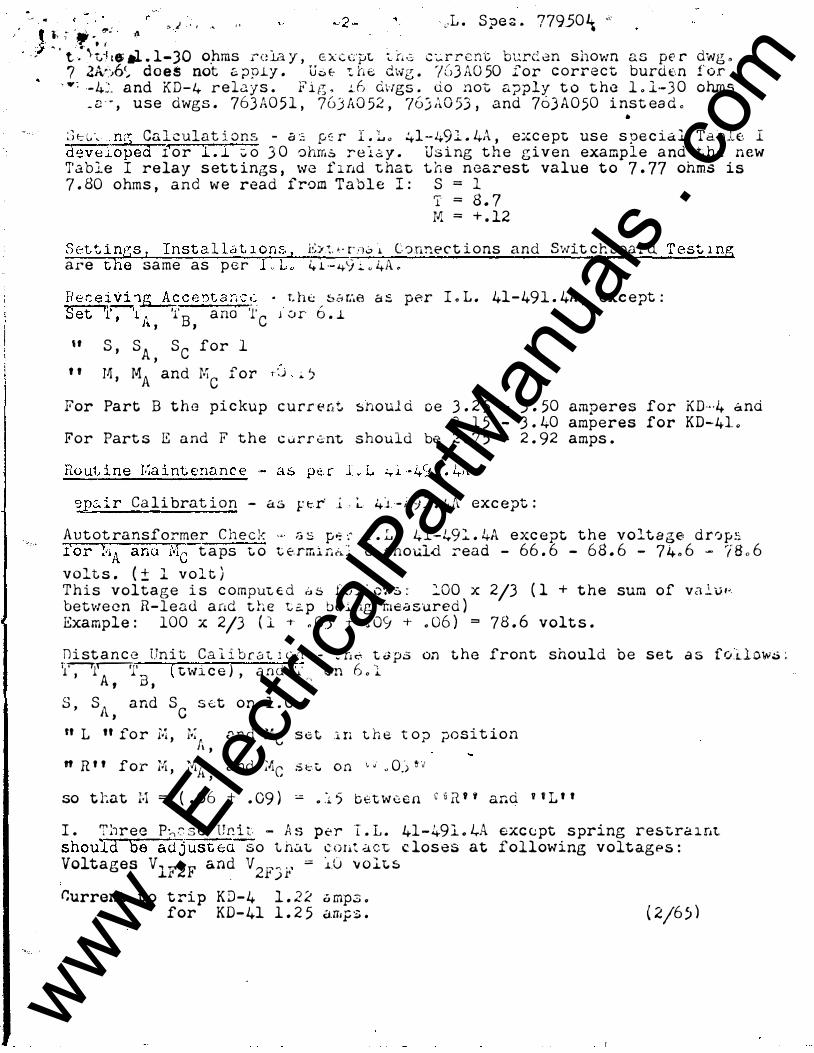
., .. ' ' t }. ; .... � 1!1': /l � ) • ' ., "
;;: ..... .. ' f �L . S pe � . 77950 � �
- - ' t . � t,;1 t& al . l-30 o_hms rela y , c x c f;'_IJL i.. [, .:;; c :.:. r r c nt. bt:rci an shown a s pe r 7 ?.A/)6'� d o e $ not c;, ppl.y . U.;. t- ":. lu;; dws . '/Cl3 AO 50 for c orr e c t burd 6n
"'"; --4�- and K D - 4 r e L1 y s . F' i g . .1.. 6 dv1gs . do not a;;ply t o t he 1 . l- 3 0 _ <:; - · , u s e dwgs . 763 A0 5 1 , 763 A0 52 , 76) A0 5.3 , and 763 A 0 50 i nst ea d • ..
dwg . for ohms
S t G � n� Calculat i ons - a � �� r I . L . 4l-49l . 4A , exc e pt us e s pe c ia l Ta ole I deveLo ped r o r l . l � o .3 0 ohms r e l a y . Us i ng t h e g i v e n example a nd t he n ew Table I re lay s et t ings , we f lnd t hat t h e n earest value t o 7 . 77 ohms i s 7 . 80 ohms , a n d w e read from T a b l e I : S = 1
'I = 8 . 7 M = + . 12
S ett i nGS 1 I n s t a l l� t 1 o n s , E)� •· rn� � C � nne c t i ons and Swit c hboa rd T est 1 ng are the same as p e r 1 " 1 . 4 1 - 49 � . 4A . nece� �ce'1t a r. c t:_ · r. h t: , ::�& r:.e a ::. per I . L . 41- 491 . 4A , exc ept : Set T , �A � B a na t c J o r b . �
" "
, , s , SA S c for 1 , r� , MA and IJ!C for 1 �; � 'J
For Part B t h e pi c kup c u rr e rtt �moul d o e 3 . 2 5 3 . 50 amperes for KD·· ·4 a nd 3 . 1 5 - 3 . 40 amperes for KD-41 .
For Part s E a nd F t h e c ..� r r .::: nt should be 2 . 7 5 - 2 . 92 amps .
':)p,:. i r Ca li brat i o n - a s p: r· . .i. , �. 41 - 49 .:.. . 4A exc ept : A u t ot ransformer C h e c k � a s p� r I . L . 4l-49: . 4A exc e pt t h e volt a ge dr0ps '.t' o r t.,A anJ l'•Ic" t a ps t o t. E'.rrr.l n o. : t3 should. read - 66 . 6 - 68 . 6 - 74 . 6 - 78 o 6 volts . ( ± l v o l t ) T h i s voltage i s c omput. t d � .. s f o � � ows : .:oo x 2j3 ( l + t he sum o f va 2. v " betwe e n R - l e a d a nd t h e t � p be l ng measured ) Example : 100 x 2j3 ( l -t· . O.J + . O<j + . 06 ) = 7 8 . 6 volt s .
D i st a n c e Un i t Ca i i b r a "C. l u �t - : n .-:. t a ps on t he front should b e set a s fo.d ow� ; ;1�...----rr· ( t \vi c e ) , a nd ·.�.· _ on 6 . l
' A , B , c S , S \ a nd S s �t o n 1 . 0 J , c " L " fo r ' " '· . nnd ;�;c s e t l' ' l'i . , A , " R " f o r ' r l'1 , ;�tj a nd
l. ' ;'"c S f...-: t
l n t h e t o p po s i t i o n
o n ·� ·.i " 0.) ' J
so t tat M = ( . 06 + . 09 ) - . l 5 b e t w a e n c & R ' ' and ' ' L ' '
I . T :1 r e e P-.. � s e Ur.. i t. - A s pt'r I . L . 41 -491 . 1,..4. exc e; pt s pring restr.: n nt. should be adjust E;U so t h.:J.L c o n.: ;..ve t. c los es at following volt agP s : Voltages V lF2F and V 2FJ F = J..G v o lt s
r.urrent t o t ri p K D - 4 1 . 2 2 o mp3 . for KD- 41 1 . 2 5 a rr1p s . ( 2j6) )
www . El
ectric
alPar
tMan
uals
. com

www . El
ectric
alPar
tMan
uals
. com
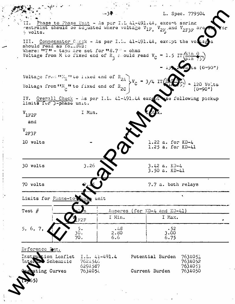
j� ". ··- ·� ... - ... � f ( .. •
tJ,.ilr � •• "' .l" ,.. ' • • , ' .. L . Spec . 779 504 '��� "';
. _ . , �" : / -: , I, .,.•
� I I . Phase t o ?ha s e U n l t - A s p o r I . L 41 - 491 . 4A , exc o nt s pr i ng .�e st. ra i nt should oe a d j ust ed where v o lt .:;.ge VlF V2 F . and V2 FJ � a r e ? volt s . ' ) •
I I I . Cor;1p_ensator C: �k - As per I . :, . 41-2,.91 . 4A , exc : ;> t t he voli. ages should read a s fo��ow3 : \'vnere : " T " - t a o:.; .'l re s et for " E L 7 ... ' - ohms Voltage from M -c o fixed er.d of RJ �· ould read V C = 1 . 5 rr f��n � "_) \S ... n , _,'j
Volt a t; c f r ... • . :; n :.;A ' ' t. o l L x e d f:.nd of R2A1J V == 314
Voltaga from ' ' Mc
'' t o f lxed end of R2 C C
I V . Overa l l C h e c � - A s p e r I . L . 41 - 491 . 4A exc ept use following p i c k up limi t s fvr ) -phase un � � .
VlF2F
and
V2FJ F 10 volt s
3 0 volt s
70 volts
I Mi n .
) . 2 6
1 . 22 a . fo� KD-4 1 . 2 5 a . for KD-41
3 . 42 a . KD-4 3 . 50 a . KD-41
7 . 7 a . bot h relays ---------------------------------------------------------------------------Limi t s for Pl1 a s e -t o - ?bes s e unit
T est # Vo H. s P. i;me.:.�es Vl F2 F I Mi n .
5 . . 48 3 0 . 2 . 80
5 , 6 , 7 ,
70 . 6 . 6
Referen c e Dl·m: . I�st ruct i on Leaflet I . L . 41-491 . 4 1nt ernal S chema i:. i c ?62 :� 54G
629A 58? Operat ing Curves 763A0 5�
( 2j65)
{ for '"D 4 ;\ - and KD-41 ) I I rt.ax .
• 52 3 . 00 6 . 7 5
Pot ent ial Burden 763A0 5� 763A0 .52 763 A0 53
Current Burden 763 A 0 50
·�
www . El
ectric
alPar
tMan
uals
. com

. . '
www . El
ectric
alPar
tMan
uals
. com

- ----- - � ' . -. ---:·� .. c '•
,.- �- -- --- - --- . - -- -- - 7 - - =--- J 'I -- . ·r -- -- -�-- -
--.. --
,-
T
TA� I
RE LA Y SETT I!;G s r vR K D - 4 and KD- 41 ( L . S;:; e c . 779 �C'�lT1 ..
--------3-=--; ---· - . ---.... ------ -+ __ ][i_: �-- ·J ' -- S =-�- t 11 1·1.-�- l���-� �-;1i ��-� �--·-. .. • I � 4. ,.J..l __ ;� ��
tt � ie ·�· 1:: � t ,, > 0
:: ·;· � -1
:t�·::���: ::-,��;:"t: :::it·: ::�:�ll � -r::-J i :����-- - · w:: --t���- --·
I 1 - • .- .- l - 0 � � 1 • � --- � _, , _ • I .... , . ,. � 1 '-" --' '--' ! / • '-' '-' 1 1 ·'- .._ • V I -' 1 • 7 j l - j "- V o / I I ! - • "-' / J l 0 , OJ I" - - -.-----r� .��l; . ���--, l�-���r6-� 5�-,-;_ 2;!f13 .-: ,-1-;5 ,-, -� -���;n--1� �,- l l"n�-T---r::-·· 1 1 - . - - - - -----.-- ------ . ---- · -- -- ----------- - ------ ------.-1
- 28 . 7 __ _ _ , _ _ t_2 . l� �r� . ��-�--, h-.�:J 6 . 9�J 9 . ���� 1; . 9 1 19 �;1;- _ 29 . 7 __ -----��� -�} ? � ��---- t . 09 _ J?� , I I !- 1_.?_06_1 3_._s s l 5 . 1 2 Lh�l.lo . 2o!L-'-} . l, 20 . l; rr;. 5 30 . 7 - -- -=-� J �JJ. 03 -'-� 06__ � ' 1----4---l----L_-_:._[}�?r-=--__ L-:...JlQ_!_£0 11� . 9 21 . 2 �
- 3 1 . 8 _ �--J_-� _)__Jt o L�- ·-
v
(" .. � ... · - . i -
,o
., ..
( /"//
www . El
ectric
alPar
tMan
uals
. com

. '
www . El
ectric
alPar
tMan
uals
. com
www . El
ectric
alPar
tMan
uals
. com

------------------
www . El
ectric
alPar
tMan
uals
. com
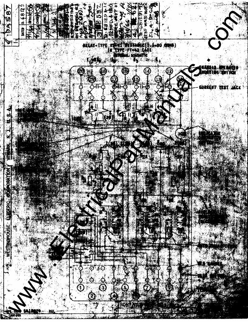
www . El
ectric
alPar
tMan
uals
. com

0
www . El
ectric
alPar
tMan
uals
. com

I .. . ' ..
"
' . I (/)'-! �40 o . · z
0 0 · " . lJ.J 1 2 0
. ,. , .,� . · · -�-d
�- ::! t qo I z .,... • )
.
l4J·.' ,;1{ �1 -� 8 0. \ ··�� . .
-. < -\ I· · ,
. . ... . �<.!) ..-\
,:; ·� GQ �- <r · a:
. · \.i.l � F .\a. - 4 o . ·�·�P . , I
I
.
�·
\ .
,. . I
.
', I·• . ?�E�AT I N G T I M E I N C Y C L E S .11
.
PHAS'E TO P H A SE U N I T � ' . ' \, I
- � f\ . , --
. ' ' ' 1\ 1\ l' l\ \
� \ . �� [\ ��� � . 'I �- �
\
) •
. L O C AT t· O N OF FA U LT I N 0/o . O F R E L AY SETT I N G
tr 90 °/o · I. JIJ 75 .,.
1/;v- so of. � 1 0 °/o 1':[7� /0 �'· .
rl/ � V ' ....... � � lL' --
M :7 h' r--.. r--r---
"" ...... L . -... -.... "'--.... -.... .....;: -)< '
� . : .l .)
9 -
" 8 -
' 7_;,
6 -<
5 -
4 -
3 -�
2-
1 -
: ·; ...
l. .. -' .
. ..
3.A 0 54 . .
C::: ! . ·"":). },d 'l0 •:t-· . .
¢· � l;.'
'OPE R AT I N G T I M E I N CY C L E S --�
- O PERATIN G TI M E IN M ILLISECONDS -- 4 :
' I ,.
140
1 20
1 0 0
80
60
40
2 0 _-,
f- .
IJ --·-�
.. - --- ---- . · "· . .. . . . - - --- . ..
i I .
I I
. l '\ '
\ t\ \J
I \ � I . \.� v ' "
'
. . --f--- -��--=-- ---- -� -- .. -3 PHAS E UN IT
""
� �) � ' --...
.
// v/ S<:J .......
"""
....... � ' . --
�
. --
' "
LO CATJON OF fAULT tN , «ro OF REL�Y S£T T I NG S .
v 90�o t,?:;v-75'% '--- ... -�--... �
· / so% ·---
// v/ r- 0.% . // � / ; "/ L ... �-- ---- . . _._.
�
"
':i·
-(1 '
·- - · ---- -- . -..._ ........ ......... ' .,_ ...
....... --!Jo....
-·-�-
� .....,;.., -
o-.;.,c ';c--· • .. · - .. l 1
. .. -
. --· -- - �-
i '•
�' . 9 -
i 8 -
' 1 r '6� �-
' 4 -- ( _ 3 ' 2
. I
""• :�
.S:
i i ' t . ; • i 1
: ;:. · lO 20 30 '40 50 6 0 . · ?o eo 90 o t o
I Z 9 (CURRENT . T IME lMPEOANCE
,.2 0 3 0 40 50 SETTING } .
� \
80 . $Q , . �; . . 60 70 ·' l t
·:.;;. . ..... .., ��
• '
www . El
ectric
alPar
tMan
uals
. com

0
www . El
ectric
alPar
tMan
uals
. com
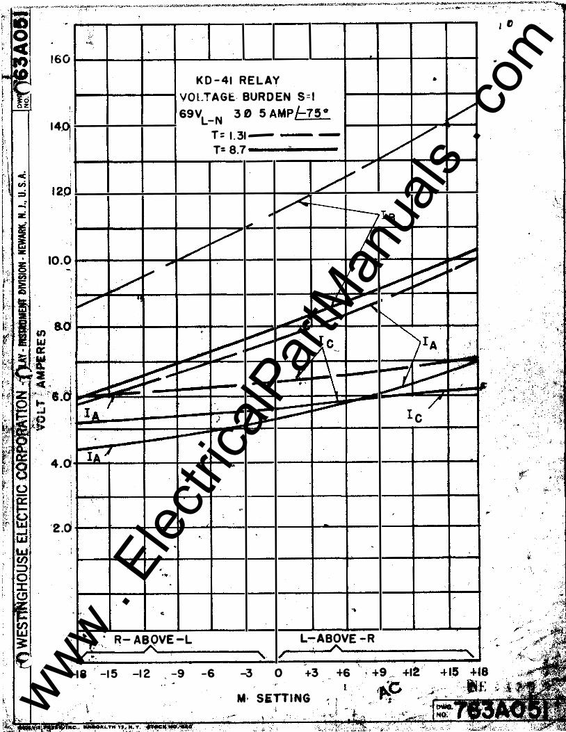
,/_/ � 160
i ! 1 4-9 I
' ' ;
10 .0
v 1 V" '! I • \
i � ' -::!fJff' ' · lA I '
,.
4.0 r-IA /
'· '
' '2.0
' ... .
.
, �
�
'
. . .... . c.
. K 0 - 4 1 RE L AY *
VO LTAG E BUR D EN S = l 69VL- N 3 0 5 AMP/-7 5 °
T = 1 . 31 - - v T= 8.7 � v
/ � 7
0 � r---iJie t-
/ v I
v � � I --
� � ..
__, � . ::::::
�r c JrA
� _,.,- )\' � -
� / _l _ - -
Q � • \ /
� � I c ; ,....,...,
.. '
.. : ' . -
. -·
� - . R- AB OVE -L L-ABOVE - R ' f • . , '
..� � ' '
' /\.
-18 ' -1 5 -1 2 ' -9 -6 A
' / I A -
-3 0 +3 +6 ' . +9 .. +12 ' '· I ·e M· SETTING .� ' _ 'Pi- ··· i i
l D
v
"""" �""'
' -! ,. , -
� ,( .It:
. ;', i
' '!'{"
\
: .•
'
www . El
ectric
alPar
tMan
uals
. com

www . El
ectric
alPar
tMan
uals
. com

' 7.0
6 . 0 I
' '· '
5 . 0
)
!
2 . ()
L ()
-
' ·,
'-'•
.
>� "
�
'
I
1
'
K D - 41 RE LAY VOLTAG E B U R D E N 5 7 3 6 9VL- N 3 0 . 5 AM P/-7 5°
T = 1.31 - t -T = 8. 7
'
' I\
I I a
' IA 1\ I -
I
.
... � , ,, ., ,, •
•
Ic �-\ '
' \
i\. .. : - -
'
'
, ,
l ....
} .. ,
'
'
, . . .
� · '
'
'�\; . $
:� ' � ;:�); !� "t �
.
R - A BOVE - L 1 L- A BOV E - R / A
. I 1 -- 1 8 - 1 5 -1 2 -9 -6
' I
-3 /
I· 0 +3
�- .... . M SETTI NG,_ '
A ' . f "", . I , + s +e +i a � ;;.+�s +1& ,
'<!!- 1'· "" • ' ' �
¥'.:· f , ., '.. .•r ;,;;:;;
;-: www .
Elec
tricalP
artM
anua
ls . c
om

www . El
ectric
alPar
tMan
uals
. com
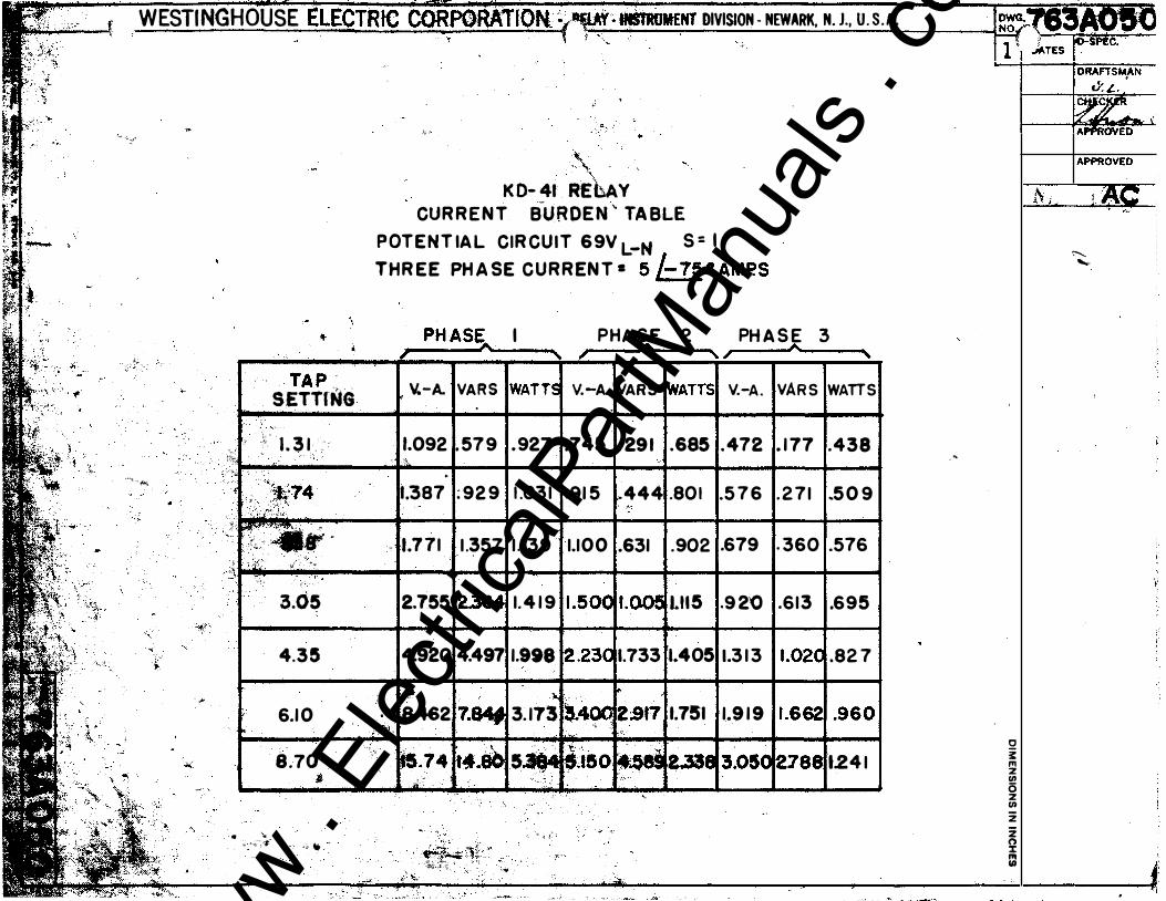
WESTINGHOUSE LL.Lu
.,, -. �·�
_ ,�-.... ,
�-\ - �
"'
•,"': "!1'
{ . _,..
....
" ' .
TAP SETTING
' ""-'�-
_ , ;; · 1 . 3 1 . �· �- " - " :��� "'-·· '
f ' ' ''tt,74 . , ;;r.I:;;,t �- �' •. · 'il . : (, c : r . . �j ' . . �� ·: · ·· ...
·�;. . . I ' --· · (·· ·
3.05
4 . 35
6.1 0 r
.
8.70 ' j
• " "·t:- -� .:, ..
. �-.•;: t
\;. . '\.
K D- 41 REbAY CUR R E N T B-URDE N " TA BLE
DIVISION - NEWARK, N. J., U . S. A. -·· .
P OT E N T IA L CIR CU I T 6 9V L-N S = I THR EE PH A SE C U R R EN T • 5 /- 75 ° AMP.S
PH ASE I PHA SE 2 PH A S E 3 ____ A A A'---_, ' , , , ' V.-A. VAR S WATTS v.-A. VARS WATTS v.-A. VAR S WATTS
1.092 . 579 .927 .745 . 29 1 .685 .472 . 1 77 .438 - . ·:-, '·
.
1.387 , ,
•: 1.7 7 1
. '
2.755
4.920
,,,. &462
: 92 9
1 .357
2.364
4.497
7.84f
1 .03 1 .91 5
1 . 139 1.100
1. 4 1 9 1 .5 00
1.998 2.230
), 3. 173 �-400
-444 .801 .5 7 6 . 2 7 1 -5 0 9 ' �
.631 .902 .679 . 360 .576
l.OOfl Lll 5 .9 2'0 .6 1 3 .695
1.733 1.405 1.3 1 3 1 .02C .82 7
!<> 2917 1.751 1.9 1 9 1 .662 I .960j
,';":J: .,. .. "
�-. �
�.74 t ••• ..,... ..;. 5 --: ' �.{� . <' � -· ,.
� ... :tL� . , ,· · -���--:::�� �-� : l ., ·•
·'¥• ,:Jso ' .
�r;& .... i. r,,
. 2.338 3.050 2788 t.24 1 I i
- �
0 � "' z 1/) 0 z 1/) z � "' Ill
('.._ '-
www . El
ectric
alPar
tMan
uals
. com

..
www . El
ectric
alPar
tMan
uals
. com