western power substation design standard review - d99672 - softcopy... · western power substation...
TRANSCRIPT

WESTERN POWER
SUBSTATION DESIGN STANDARD REVIEW
Prepared by Hydro-Electric Corporation
ARBN: 072 377 158 ABN 48 072 377 158
4 Elizabeth Street, Hobart Tasmania, Australia
30 September 2008
PROJECT/JOB � 203677 Hydro Tasmania Consulting Revision No: 1
30 September 2008 2
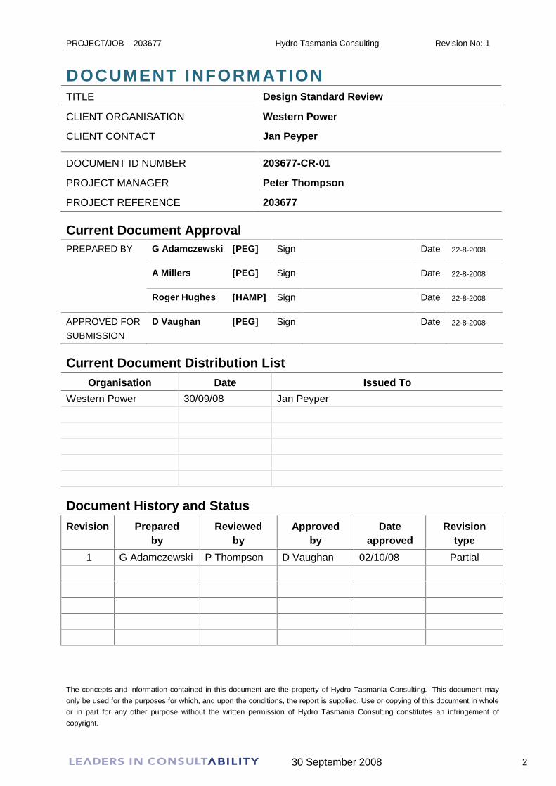
DOCUMENT INFORMATION TITLE Design Standard Review
CLIENT ORGANISATION Western Power
CLIENT CONTACT Jan Peyper
DOCUMENT ID NUMBER 203677-CR-01
PROJECT MANAGER Peter Thompson
PROJECT REFERENCE 203677
Current Document Approval PREPARED BY G Adamczewski [PEG] Sign Date 22-8-2008
A Millers [PEG] Sign Date 22-8-2008
Roger Hughes [HAMP] Sign Date 22-8-2008
APPROVED FOR
SUBMISSION
D Vaughan [PEG] Sign Date 22-8-2008
Current Document Distribution List Organisation Date Issued To
Western Power 30/09/08 Jan Peyper
Document History and Status
Revision Prepared by
Reviewed by
Approved by
Date approved
Revision type
1 G Adamczewski P Thompson D Vaughan 02/10/08 Partial
The concepts and information contained in this document are the property of Hydro Tasmania Consulting. This document may
only be used for the purposes for which, and upon the conditions, the report is supplied. Use or copying of this document in whole
or in part for any other purpose without the written permission of Hydro Tasmania Consulting constitutes an infringement of
copyright.

PROJECT/JOB � 203677 Hydro Tasmania Consulting Revision No: 1
30 September 2008 3
EXECUTIVE SUMMARY
Hydro Tasmania Consulting was engaged by Western Power to undertake a high-level
review of a set of documents that it had prepared to standardise and document its current
approach to substation design. The documents cover:
Western Power�s Transmission Standard Designs Policies,
Functional and conceptual requirements for 132/22 kV Zone Substations and
330/132 kV Terminal Yards,
132 kV Underground Cable Circuits
The review covered three key areas; Primary, Secondary and Civil design. Comments on
detailed aspects for each of these disciplines are included in Section 3 of this report. These
comments are intended to improve document readability and cross-referencing, and amend
minor errors.
In general the review found that Western Power�s approach is considered, well documented,
and based on philosophies, design parameters and methodologies consistent with, and
currently being implemented by other utilities in Australia.
It was noted, however, that the documentation provided does not include the underlying
technical reasoning behind some of the requirements or methodology in the documentation.
As this documentation is intended to be a knowledge capture, it is recommended that the
design reasoning also be documented as an aid to those undertaking future design revisions.
A good example of such a document is Western Power�s �HV Extruded Cables Design and
Installation Guide�.
It is understood that Western Power is currently undertaking a project to review its future
substation requirements. These documents provide an excellent starting point for such a
review, which can include consideration of alternative technologies to Air Insulated
Substations (AIS) such as Gas Insulated Switchgear (GIS) and Mixed Technology
Switchgear (MTS).
The review process was necessarily at a high level but Hydro Tasmania Consulting is able to
provide additional assistance in specific areas, including consideration of future technologies,
if this is required.

PROJECT/JOB � 203677 Hydro Tasmania Consulting Revision No: 1
30 September 2008 4
CONTENTS 1. Introduction 5
2. Project Scope 6
3. Document Review 7 3.1 Primary Design 7
3.1.1 General 7 3.1.2 Electrical Clearances 8 3.1.3 Electromagnetic Fields 9 3.1.4 Critical Infrastructure 9 3.1.5 Functional Specifications 132/22 kV Zone Substations 9 3.1.6 Functional Specifications 330/132 kV Terminal Yards 11 3.1.7 Functional Specifications 132 kV UG Cable Circuits 11 3.1.8 HV Extruded Cable Design & Installation Guide 12 3.1.9 Concept Design 132/22 kV Zone Substations 12 3.1.10 Concept Design 330/132 kV Terminal Yards 14
3.2 Secondary Design 15 3.2.1 General 15 3.2.2 Functional Specification 330 / 132kV Terminal Yards 16 3.2.3 Concept Design - 330 / 132kV Terminal Yards 16 3.2.4 Functional Specification 132 / 22kV Zone Substations 18 3.2.5 Concept Design - 132 / 22kV Zone Substations 19
3.3 Civil Design 22 3.3.1 General 22 3.3.2 Infrastructure 22 3.3.3 Functional Specifications � 330/132kV Terminal Yards 23 3.3.4 Concept Design � 330/132kV Terminal Yards 24 3.3.5 Drawing Template - Terminal Yard � 330kV 26 3.3.6 Functional Specifications �132/22kV Zone Substation 28 3.3.7 Concept Design � 132/22kV Zone Substations 29 3.3.8 Drawing Template - Substation � 132/22 kV 31 3.3.9 Concept Design for 132kV Urban Wood Pole Lines 32 3.3.10 Drawing Template Standard 132kV Urban Wood Poles 33
4. Summary 35

PROJECT/JOB � 203677 Hydro Tasmania Consulting Revision No: 1
30 September 2008 5
1. INTRODUCTION
Western Power has completed a review project to standardise its current designs to address
inefficiencies and inconsistencies across the design function. Hydro Tasmania Consulting
was engaged by Western Power to review these standards for the following three key areas:
Electrical Primary Design
Substation Electrical Secondary Design
Civil Structural Design

PROJECT/JOB � 203677 Hydro Tasmania Consulting Revision No: 1
30 September 2008 6
2. PROJECT SCOPE
The scope for the project was:
To obtain all documentation and drawings to facilitate an initial review and identify
opportunities for potential improvement or clarifications, along with any suggested
fine detail modifications
For the three discipline leaders from Hydro Tasmania Consulting to meet with
Western Power Representatives to discuss the output from the first stage and any
other broader issues that require resolution
To complete the review report and dispatch this at least two weeks ahead of a
presentation at Western Power.
Hydro Tasmania Consulting was advised at the meeting held at Western Power that the
documents to be reviewed were prepared as a knowledge capture exercise. The purpose
was to document the basis of design and the designer�s intent that had been involved in
preparation of the standard:
132/22 kV Zone Substation design;
330/132 kV Zone Substation design; and
Cable Installation design.
The documents have been reviewed on this basis.
PROJECT/JOB � 203677 Hydro Tasmania Consulting Revision No: 1
30 September 2008 7
3. DOCUMENT REVIEW
The documentation supplied has been reviewed for consistency and technical content. The
functional and scope documents for the zone and terminal substations and cable design has
been edited using Microsoft Word�s Track Changes feature to simplify the capture of editorial
changes.
The review has been carried out taking into account Western Power�s draft Transmission
Standard Designs Part 1 - Policies.
Each of the document parts were reviewed for clarity and from a high technical overview
perspective. The following is commentary on the three disciplines to be addressed: Primary,
Secondary, and Civil Design.
3.1 Primary Design
3.1.1 General Review of the supplied documentation reveals that Western Power has adopted a specific
approach in designing its 330 kV and 132 kV networks and that the standard designs
provided have been developed to facilitate this approach.
The documents provide a good overview of Western Power�s approach for the substations
but, from a newcomer�s perspective, an explanation and examples of how they fit into the
system would assist in understanding how the substations enable the system development
philosophy.
The following are general comments for improving the documents:
There is an inconsistency in the use of the words �shall�, �should�, �will�, and �would�.
This should be reviewed to ensure those items that are mandatory are clearly and
consistently identified.
In a number of places generic or non-specific terms are used that to convey the idea
that best performance is required but do not define what that ultimate is, eg use of the
terms �optimum impact�, �optimise the operation of the substation�, �minimum impact�,
greater than, etc. This may be acceptable for internal use of the documents but
would nevertheless aid interpretation if these concepts were clarified.

PROJECT/JOB � 203677 Hydro Tasmania Consulting Revision No: 1
30 September 2008 8
In numerous places references are made to other documentation, such as �DMS
Reference No. 347636v2�. It is recommended that that the version number be
removed so that it reads �DMS Reference No. 347636� because the document will
need to be updated every time the referenced document is altered. This additional
step is likely to be omitted in practice and could cause confusion or serious error. A
general statement should be included indicating that �the latest version of referenced
documents shall be used�. The referenced documents should also include a
cross-reference advising the editor to review other documents to ensure any changes
are properly captured and addressed.
Consideration should be given to standardising the introduction to each document
part. This could be achieved by having the first four sections the same, or combined
under one main heading with sub headings.
Abbreviations used in the document should be clearly stated at the beginning of each
document part. In some cases within the document there is a mixture of abbreviations
with the full description.
3.1.2 Electrical Clearances The electrical clearances adopted by Western Power are in accordance with the current
AS 2067 but should be reviewed when the new edition of AS 2067 � High Voltage
Substations is released (third quarter of 2008).
It is noted that the table supplied does not require provision for additional phase-earth and
phase-phase clearance for birds and vermin at voltages up to 22 kV, as is typical for some
authorities.
Some authorities specify minimum clearances that vary from those in AS 2067. For
example, one authority has adopted the following values:
Voltage (kV) Phase-Earth Clearance (mm) Phase-Phase Clearance (mm)
22 280 450
66 690 800
220 2,300 2,650
330 2,850 3,300

PROJECT/JOB � 203677 Hydro Tasmania Consulting Revision No: 1
30 September 2008 9
3.1.3 Electromagnetic Fields As a general comment it should be noted that the ARPANSA recommendations for allowable
electric and magnetic field exposure have not yet been finalised. However, it is strongly
recommended that EMFs are minimised at the substation boundary as far as is practical.
Recently a local council stipulated that the maximum level they would accept is 2 mG, a level
that is extremely difficult to achieve in practice. For this reason, power transformers and
reactors should be located near the centre of the substation to minimise the boundary
magnetic field.
3.1.4 Critical Infrastructure Authorities in some states are reviewing security at their critical infrastructure such as
substations and are applying differing security measures, depending on the accessibility of
the site and its importance.
The documentation provided indicates that varying standards of security are applied, but
does not refer to risks of terrorist attack. There are simple security measures that can be
adopted, such as introducing a tight bend in access roads near the substation so that vehicle
speed is controlled to minimise the risk of �ram-raids� being successful.
Cigré Technical Brochure 253, �Substation Physical Security Trends�, was released in 2004
following an international survey and provides data on security strategies adopted by
authorities in different countries.
3.1.5 Functional Specifications 132/22 kV Zone Substations An edited electronic version of the supplied document is included with this report. The
following comments relate to key issues identified in the document:
Section 4. Definitions
The definition for Transformer Maximum Continuous Rating should identify that it is
applicable �in the Rated Physical Environment�.
Section 6. Substation Electrical Specifications
The reference to �Extended Service Environment� should refer to �Extended Physical
Environment�.
Section 6.3, Figure 1: Zone Substation Single Line Diagram
Surge arresters are not shown on the 132 kV line entrances (they are shown on
drawing SS1/30/5/500/1).

PROJECT/JOB � 203677 Hydro Tasmania Consulting Revision No: 1
30 September 2008 10
Section 6.5.1 General
NCR is referenced here � it should be defined as Normal Cyclic Rating at its first
occurrence.
Section 6.7 Reliability
The term �Outage Rate� should be defined at the beginning of this section.
Section 6.12 Substation Lightning and Earth Potential Rise Protection
Should include statements re:
Whether or not the earthing system is to be a stand-alone system � ie whether or not
it must meet the required performance without assistance from external earthing via
cable screens, overhead earth wires, etc.
The limits of surface voltage rise outside the substation during an earth fault � eg it
may be a requirement to contain the 1000 V surface voltage contour within the
substation site security fence.
Whether or not the earth grid is permitted to extend beneath and/or include
connection to the security fence.
Section 7.1 Substation Site
Reference should be made to whether or not provision is to be made for crane
access, lighting, and fencing (both perimeter and security).
Section 7.2 Substation Site Selection
Adverse Conditions � �resistance� should be �resistivity�
Vehicular traffic � Comment could be added re prevention of ram-raids and whether
or not vehicle barriers, etc are required or permitted within the substation.
Landscaping � it may not be practical to meet community expectations: eg there
may be a requirement to build it underground so that it is not visible. This wording
may require further definition.

PROJECT/JOB � 203677 Hydro Tasmania Consulting Revision No: 1
30 September 2008 11
Section 7.4 Substation Building
The BCA does not specifically cover substation buildings and this should be
addressed in this section.
Section 7.4.1 Switchrooms and Relay/Control Room
Footnote 14 should be corrected to read �� does not have any direct means of
access to another area�.
Section 8.2 c) Life Cycle Costs
This could include reference to selecting MV/EHV power cable cross-sectional area
such that the capitalised value of losses and the cable cost are minimised over the
cable life (the capitalised value of transformer load loss can be used to establish this).
Section 8.6 Environmental Compliance
Dust � add to end of first sentence �� and contamination to substation insulation.�
Services and Auxiliaries Interfaces � ensuring that step and touch potential rises
and electromagnetic fields, etc are managed on site and not transferred off-site is not
practical. Limits of EMF and the allowable surface and transfer voltages at the
substation boundary during faults should be nominated. Reference may be made to
ARPANSA requirements for EMFs when these are finalised (currently under
consideration).
3.1.6 Functional Specifications 330/132 kV Terminal Yards Similar comments to those made in the previous section also relate to the Functional
Specifications 330/132 kV Terminal Yards document.
3.1.7 Functional Specifications 132 kV UG Cable Circuits This document covers the requirements for a cable installation in a clear and concise
manner. A few comments are included below:
Section 6.2.5 Communications and cable Monitoring Facilities
Requirements for the distributed temperature system monitoring equipment are not
identified.

PROJECT/JOB � 203677 Hydro Tasmania Consulting Revision No: 1
30 September 2008 12
Section 8.6 Environmental Compliance
The adoption of 4 mG as the upper limit of magnetic field is consistent with the levels
being adopted internationally (refer comment in Section 3.1.3 above).
3.1.8 HV Extruded Cable Design & Installation Guide The document provides a good and comprehensive overview of the principles that underlie a
cable installation design. The reasons behind preferred installation methods, such as flat
spacing vs trefoil arrangements, are documented and provide a solid background for future
design modifications.
3.1.9 Concept Design 132/22 kV Zone Substations An edited electronic version of the supplied document is included with this report. The
following comments relate to key issues identified in the document:
Section 4 References and Standards.
If the concept design document is issued to external parties for implementation then it
is recommended that a statement be included to the effect that a proposed list of
alternative standards be submitted to Western Power for acceptance/approval.
Section 5.1 Introduction.
Substation Buildings � There is no reference to the required Earth Stick Building
Site Works � It is recommended that a distinction be made between the site security
fence and the site perimeter fence (assuming one is required). The R&M building is
not defined.
Section 5.2.2 Standard Dimensions and Minimum Electrical Clearances
The Standard Dimensions table refers to �height above foundation�. It is unclear if
this is intended to refer to �height above switchyard finished level (ie surface level)� as
this may be more appropriate.
It is suggested that Appendix 3A be reserved for the Single Line Diagram as this is
the key drawing for the substation and that Appendices 3B and 3C be for the
Switchyard Layout Drawings.
Section 6.1.1 General Description
Some sections of AS 2374 are now replaced by AS 60076.1 and AS 60067.4

PROJECT/JOB � 203677 Hydro Tasmania Consulting Revision No: 1
30 September 2008 13
Section 6.1.2 Size and Ratings
In the second sentence the phasing and connections when viewed from the
transformer HV side should be reviewed.
Section 6.1.3 Design Basis
The table of transformer dimensions does not clearly state whether or not the
dimensions include the coolers.
If the document is issued to others, permission should first be sought from Wilson and
EBG for the data to be circulated.
Section 6.4 Combined CT/VTs
Some authorities refer to these as CVCTs (Combined Voltage and Current
Transformers).
Section 6.6.2 Size and Ratings
�The surge arresters will be of the metal-oxide gapless type and comply with
AS 1307.2, with a nominal discharge current of 10kA and line discharge Class 3.
Further detail are contained in the table below:� should be replaced with �The surge
arresters will be of the metal-oxide gapless type and comply with AS 1307.2 and the
table below:� to eliminate duplication of data.
Section 6.7.2 Design Basis (Lightning Protection)
It is noted that lightning masts may be used to mount light fittings. Is there any
evidence of lightning strikes to masts causing damage to lighting cabling?
Section 6.9.3 Design Basis (Busbars and Connections)
The sentence below the table refers to �The above maximum span� but there is no
other reference to this span.
Section 6.12.1 General Description (22 kV Capacitor Bank Feeders)
Some of the data provided is repeated in Section 6.12.2.
Section 6.14.1 General Description (Substation Services Transformers)
Reference to �off load� tap changer should be �off circuit�.

PROJECT/JOB � 203677 Hydro Tasmania Consulting Revision No: 1
30 September 2008 14
Section 6.17 Substation Earthing System
Drawing SSTTT/3/4/1 shows an internal and external grading ring at the security
fence. It is possible that the internal grading ring may not be required and comment
should be made that this should be reviewed. Note that, to reduce the risk of
inadvertent voltage transfer, in some jurisdictions it is not permissible to connect the
security fence to the earth grid. In this case the grid must lie totally within and no
closer than 2 metres from the security fence.
The document could note that the forthcoming ENA Earthing Guide, which provides
for a probabilistic earthing design approach, is due to be released in the near future.
The document should state whether a probabilistic approach is acceptable.
It should be stated whether or not the resistivity of the surface layer (eg crushed rock)
is permitted to be taken into account when calculating allowable step and touch
voltage levels. This is allowed for in the ENA Earthing Guide but is not permitted by
some authorities. The minimum, thickness and resistivity of this layer should be
specified (eg 100 mm, 3,000 Ùm).
It should be stated that it is mandatory for the earth grid to be tested by the current
injection method (it is not clear if this is a requirement in Section 6.17.3, which refers
to standard DMS No. 1326076.
In Section 6.17.4 it is not clear if the portable earthing systems have been tested. It is
recommended that each assembly be tested as they are safety devices. A note
should be included to ensure that, if the standard design is modified, the revised
assembly must be re-tested for the design fault level.
3.1.10 Concept Design 330/132 kV Terminal Yards Similar comments to those made in the previous section also relate to the Concept Design
for the 330/132 kV Terminal Yards document.

PROJECT/JOB � 203677 Hydro Tasmania Consulting Revision No: 1
30 September 2008 15
3.2 Secondary Design
3.2.1 General It was noted that inconsistent terms are used throughout the document; it is recommended
that standard terms be adopted.
The report uses expressions such as �sufficient electronic storage�, �serial communication
capability�, �etc�. These types of statements should be avoided or reference should be made
to a current standard document which contains Western Power�s current equipment
requirements.
To provide better clarity of Western Power�s methods, additional information could be
included in certain areas. References to DMS documents where more information is
available may be sufficient. Because DMS documents were not provided, as they were not
part of this scope, it is not clear what information is contained in these documents and how
these documents complement the reviewed documents.
It may be useful to the reader if the DMS documents listed in the appendix are grouped in
their respective disciplines.
As the document is intended to capture knowledge, there would be benefit in adding
historical information on why certain methodology is adopted within Western Power�s
network. This would help young engineers and new engineers gain a better understanding of
how and why Western Power has taken this approach.
Microprocessor relays currently on the market need to be configured; there is no mention in
the Functional Specification or Concept Design documents on Western Power�s
requirements for standardisation, e.g. inputs, outputs, etc.
Reference is made to �local SCADA System�; for clarity and less confusion, the term
Substation Control System (SCS) is recommended.
It is recommended that the term �modern� be deleted.

PROJECT/JOB � 203677 Hydro Tasmania Consulting Revision No: 1
30 September 2008 16
3.2.2 Functional Specification 330 / 132kV Terminal Yards
Section 6.14 Terminal yard Auxiliary Supplies (AC/DC)
The reference made to the 50V DC supply should state the source of the supply i.e.
from the 50V battery bank.
The DC battery capacity in hours stated for the terminal yard when loss of AC supply
occurs seems high. Microprocessor protective relays consume much more power
than the earlier protective relays; therefore higher DC battery capacity would require
a larger DC battery bank. Generally, battery banks are rated for 12 hours. If Western
Power has remote terminal yards that are not accessible within 12 hours then a
higher capacity battery would be required. Additionally this section should indicate the
battery capacity necessary to operate equipment for a specified time that meets
Western Power requirements.
3.2.3 Concept Design - 330 / 132kV Terminal Yards
Section 5.2.4 Building Design Features
-48V DC communication batteries are not mentioned and it is assumed they will be
located in the communication hut.
Section 6.11.3 Design Basis
This text needs to be corrected to meet requirements for the 132kV system. The
current text makes reference to 22kV.
Section 7.1 Protection system
The term �duplicate� is used with reference to protection under option (a) Protection 1
- Interlocked Current Differential and Protection 2 � interlocked Distance / IDMT Earth
Fault schemes. This is not a duplicated scheme.
The statement �The design shall be modular and flexible allowing easy testing and
isolation facilities.� should include more information on how Western Power lays out
their cubicles, or refer to a template (or DMS). Each power utility has a defined panel
layout based on their testing and isolation methods.

PROJECT/JOB � 203677 Hydro Tasmania Consulting Revision No: 1
30 September 2008 17
The statement �if mounted in the same cubicle, be separated vertically by a suitable
insulating material� should be accompanied with stated minimum requirements for
insulation between Protection 1 and Protection 2, or refer to a reference document.
The statement �Separate supervision relays shall be used when relays with self-
diagnostic features are not used� does not make clear what supervision is required,
for example �trip circuit supervision, loss of DC supply, etc.
Section 7.1.1 330kV Line protection
The term �speed requirements� is an undefined term, it would be better to use the
term �fault clearance time requirement�.
Section 7.1.4 330 kV/132 kV Transformer Protection
The table shown below the statement �The complete scheme will consist of
duplicated fully independent and discriminative protections.� lists Protection 1 and
Protection 2 required protection functions. The protection functions are not
duplicated; however there is redundancy between the two sets of protection.
Section 7.1.5 132 kV Capacitor bank Protection
The protection function listed does not provide protection from overvoltage across the
capacitors. It is recommended that a protection relay designed for capacitor banks be
considered.
Section 7.1.6 22/0.415 kV Station Transformer Protection
This section should be reviewed by Western Power for clarity.
Section 7.1.12 Metering Information & Indication
No mention of CT or VT requirements for revenue metering. Meters for revenue
metering are placed on separate CT cores that meet the required CT class for
revenue metering.
Section 7.1.13 Fault Recorder
The term �investigation section� is used and it is not clear if this is a Western Power
group or comes under Protection and Control. If there are standards available on
determining where fault recorders are placed, then reference should be made to this
document.
PROJECT/JOB � 203677 Hydro Tasmania Consulting Revision No: 1
30 September 2008 18
Section 7.2.1 Communication Requirements � Protection
The Statement �Duplicated digital differential protection on a three-ended line may
require a third physically diverse bearer path between two of the three sites.� should
include reference to the section that determines if a third bearer path is required or
reference to a Western Power standard for guidance.
Section 7.3 SCADA System
Reference is made to 48V DC; this should be changed to 50V DC to maintain
consistency throughout the document.
Section 7.3.1 Remote Terminal Unit (RTU)
This section should refer to a standard document where Western Power outlines its
current RTU requirements e.g. number of spare DI, DO & AI that is required and what
communication protocols are required on the RTU.
Section 7.3.7 Human Machine Interface (HMI)
The HMI supply is referred to as 48V DC and should be changed to 50V DC to
maintain consistency.
Section 7.3.8 Power Supply
The RTU supply is referred to as 48V DC and should be changed to 50V DC to
maintain consistency.
Section 8.2 DC Auxiliary Power Supply System
Refer to comment under Section 6.14 regarding battery capacity.
3.2.4 Functional Specification 132 / 22kV Zone Substations
Section 6.13 Substation Auxiliary Supplies (AC/DC)
Additional information should be added to indicate what needs to be operated at the
specified time after loss of AC supply.

PROJECT/JOB � 203677 Hydro Tasmania Consulting Revision No: 1
30 September 2008 19
Section 6.9.2 Control
Little information is given on the philosophy of how Western Power parallels its
transformers. If a DMS document for this is available then reference to it should be
included.
3.2.5 Concept Design - 132 / 22kV Zone Substations
Section 7.1 Protection system
The term �duplicate� is used with reference to protection, under option (a) Protection
1 - Interlocked Current Differential and Protection 2 � interlocked Distance / IDMT
Earth Fault schemes. This is not a duplicated scheme.
The statement �The design shall be modular and flexible allowing easy testing and
isolation facilities.� should include more information on how Western Power lays out
their cubicles, or refer to a template (or DMS). Each power utility has a defined panel
layout based on its testing and isolation methods.
The statement �if mounted in the same cubicle, be separated vertically by a suitable
insulating material� Should be accompanied with stated minimum requirements for
insulation between Protection 1 and Protection 2 or refer to a reference document.
The statement �Separate supervision relays shall be used when relays with
self-diagnostic features are not used� does not make clear what supervision is
required e.g. �trip circuit supervision, loss of DC supply, etc.
Section 7.1.1 132kV Line protection
The term �speed requirements� is an undefined term, it would be better to use the
term �fault clearance time requirement�.
Section 7.1.2 132 kV / 22 kV Transformer Protection
The table shown below the statement �The complete scheme will consist of
duplicated fully independent and discriminative protections.� lists Protection 1 and
Protection 2 required protection functions. The protection functions are not
duplicated; however there is redundancy between the two sets of protection.

PROJECT/JOB � 203677 Hydro Tasmania Consulting Revision No: 1
30 September 2008 20
Section 7.1.3 under Voltage Load Shedding
Resetting of lockout trip relays remotely should be avoided. Lockout trip relays are
reset once the faulted equipment has been inspected and cleared for service.
Section 7.1.4 22 kV Circuit Protection - General
The statement �The transformer LV overcurrent and LV earth fault protection shall
provide backup protection� does not make clear what it is backing up .e.g. feeder
protection.
The statement �When the transformer protection cannot provide adequate sensitivity,
a low impedance bus zone relay capable of measuring individual circuit currents shall
provide backup protection:� does not make clear if it is referring to the 22kV
switchgear busbar protection.
Section 7.1.6 22 kV Capacitor bank Protection
The protection function listed does not provide protection from overvoltage across the
capacitors. It is recommended that a protection relay designed for capacitor banks be
considered.
Section 7.1.12 Metering Information & Indication
Meters for revenue metering are placed on separate CT cores.
Section 7.1.13 Fault Recorder
The term �investigation section� is used and it is not clear if this is a Western Power
group or comes under Protection and Control. If there are standards available on
determining where fault recorders are placed, then reference should be made to this
document.
Section 7.3 SCADA System
Reference is made to 48V DC; this should be changed to 50V DC to maintain
consistency throughout the document.
This section should refer to a standard document where Western Power outlines its
current RTU requirements e.g. number of spare DI, DO & AI that is required and what
communication protocols are required on the RTU.

PROJECT/JOB � 203677 Hydro Tasmania Consulting Revision No: 1
30 September 2008 21
Template Drawings
Drawings submitted for review were examined and the following observations are made:
Drawing numbers: SSYYY/5/80201/1B, SSYYY/5/80201/1C, SSYYY/5/80201/1D,
SSYYY/5/80202/1, SSYYY/5/80202/1A, SSYYY/5/80202/1B, SSYYY/5/80202/1 were
examined and the following noted:
Wire number labels for the supply rails are not logical. The wire number labels are
shown on some connection branches and not on others.
The power supply connection should be placed at the end of each supply loop; this
will give better supervision of the supply rail in the event a loop connection is broken
after the cubicle fuse.
On the same sheet, connections are shown as a wired schematic and as a general
schematic.

PROJECT/JOB � 203677 Hydro Tasmania Consulting Revision No: 1
30 September 2008 22
3.3 Civil Design
3.3.1 General The supplied Functional Specifications, Concept Design documents and template and
standard drawings generally indicate that Western Power is pursuing a product and service
level that is consistent with best practice nationally. Minor suggestions or additions are
highlighted in the supplied documents that align the Civil Design content with current practice
nationally.
Currently the 1993 version of AS 1170.4 Earthquake actions in Australia, adopted by
Western Power in the documentation (which is linked to the current version of the Building
Code of Australia), is under revision. When it is reissued as a joint Australian/New Zealand
standard it should be reviewed to see if it is still relevant for Western Power�s design
purposes. An alternative is for Western Power to specify design criteria from the latest
version of AS 1170.4.
3.3.2 Infrastructure 3.3.2.1 General
The following observations on the basic guidelines for firewalls, noise abatement walls and
durable concrete structures are suggestions based on industry practice in Australia. The
comments include references to the Building Code of Australia where the terminal yard and
substation are to be constructed in potentially �built up� areas.
3.3.2.2 Fire Rating of Walls
Transformers shall be separated by a minimum three-hour fire rated wall(s) between
transformers when the separation distance is less than a set dimension which is dependent
on the MVA rating of the transformers concerned. The separation distance can vary between
25 metres reducing to 15 metres for lesser rated transformers. Refer to the Building of
Australia (BCA) Part C2 for the requirements when the substation is sited in a built up area.
The cooling requirements of the transformers shall be addressed when designing the
separating fire walls.
3.3.2.3 Noise Control
Based on noise level design calculations referenced to the substation boundaries and as
required, on site noise measurements there may be a requirement for constructing noise
abatement walls around the transformer bunds. Consideration should be given to taking into
account the future additional installation of transformers on the level off noise produced. The
level of noise attenuation required for each site will partially depend on the ambient noise

PROJECT/JOB � 203677 Hydro Tasmania Consulting Revision No: 1
30 September 2008 23
and development of residential areas. The cooling requirements of the transformers and
access to the transformers shall be addressed when designing the noise abatement walls.
For built up areas Part F5 of the Building Code of Australian should be referred to when
considering noise abatement measures.
3.3.2.4 Durability
Generally to address durability issues of substation reinforced concrete structures reference
is made to AS 3600.
In areas of reactive soils it is generally not economical to remove the soil therefore the
structures are designed to AS 3600. Installation of external membrane coatings is considered
when countering extreme conditions.
3.3.3 Functional Specifications � 330/132kV Terminal Yards Section 8.6 Environmental Compliance
Oil Filled Equipment: Addition of subsurface agricultural drains draining to sumps or
an oil containment tank especially in high water table areas can be installed to
supplement the bunded areas to capture hydrocarbon spills that result from
maintenance on the transformers or other electrical equipment.
Section 9.2.3 Physical Withstand Environment
Referencing Minimum Design Criteria for Civil Works a heading and paragraph
should present a general statement which states that the following load conditions
applies to all civil works including earthworks and structures within the Terminal
Yards where applicable, (not specifically only applicable to the �shelter�).
Referencing the listed design criteria for wind loads Western Power�s coverage zone
apply to Wind Regions A1, A4 and B, not the cyclonic region C. In turn the Average
Recurrence Interval (ARI) of 1 in 1000 years is nominated as an acceptable wind
design criteria. The Importance Level is to be revised with reference to the current
issue of the Building Code of Australia (BCA), Part B1, Table B1.2a.
Referencing the listed design criteria for earthquakes from AS 1170.4. 1993, AS
1170.0 2002 Appendix D has been provided to link the requirements of AS 1170.4.
1993 with the new requirements in Part B1 of the Building Code of Australia (BCA)
which include policy criteria in the form of importance levels and the associated
annual probabilities of exceedance. The importance factor (I) has been replaced by

PROJECT/JOB � 203677 Hydro Tasmania Consulting Revision No: 1
30 September 2008 24
the variation of annual probability of exceedance. The Structure Type is replaced by
importance level. The Acceleration Coefficient maps of Western Australian Figures
2.3(d) and (e), AS 1170.4. 1993 specifies the values to be considered at each
substation site.
Currently the 1993 version of AS 1170.4 is under revision. When it is reissued as a
joint Australian/New Zealand standard it should be reviewed to see if it is still relevant
for Western Power�s design purposes. An alternative is to specify design criteria from
the latest version of AS 1170.4, currently 2007 (where the Acceleration Coefficient
maps of Western Australian Figures 2.3(d) and (e), AS 1170.4. 1993 are replaced by
Hazard Factor (Z) for Western Australian Figures 3.2(C) and (D)).
3.3.4 Concept Design � 330/132kV Terminal Yards Section 9.1 Site
Specify the site development to include a balanced cut and fill method to construct
the platform for terminal yard sites where suitable foundation material exists. The
disturbed foundation material shall be compacted with a minimum of four passes of a
vibrating 10 tonne roller.
This section should specify the maximum cut/fill batter angles when constructing the
terminal yard platform, for example 1 on 3 for sand.
The maximum slope of the terminal yard platform for drainage purposes is to be 1 in
40. Where sites are flat the minimum slope shall be 1 in 100.
The maximum slope of the access ramp(s) from the main road to the platform is 6%
to allow the placement of the RSST unit within the terminal yard. The minimum road
width on the platform should be 5 metres with corners to suit size of transformer
delivery equipment, for example 15 to 20 metre radii.
Section 9.3 Footings
Typical footing templates should be indicated for sand foundation material, sandy
gravel foundation material and gravelly clay foundation material in Appendix 3 D.
These footing templates may consist of a typical thick slab or typical pier footing to
cover various foundation materials from predominately sand through clay to rock.
Additionally typical dimensioned footing templates, both slab and pier can be
specified to apply to Wind Regions A1, A4 and B covered by Western Power. The
templates are to be placed in Appendix 3 D.

PROJECT/JOB � 203677 Hydro Tasmania Consulting Revision No: 1
30 September 2008 25
Section 9.4 Structures
Specify the respective Wind Regions, either A1, A4 and B and provide corresponding
typical electrical equipment structural steel support templates to suit each region
assuming say Terrain Category 2, Shielding Multiplier 1.0 and Topographical
Multiplier 1.0.
Section 9.5 Outdoor Cable Trenches
Reference the required maximum traffic loading (as axle loading or wheel loading) on
the types of reinforced concrete box culverts and concrete lids in this clause or list the
relevant template design drawings that state the maximum loadings.
Specify, if relative levels allow, installing subsoil drains from the cable trench outfalls
draining to the oil containment system or dedicated sump or pit collecting stormwater
drainage prior to discharging off the site.
Section 9.6 Oil Containment
Referring to the general description and issued drawings of Western Power�s oil
containment system the outflow would struggle to comply with a limit of a maximum of
15 parts per million of hydrocarbons released into the environment if the bund Oil
Stop isolation valve failed during a transformer failure especially during a storm event
where the resultant oil/water mix would form an emulsion as it passed through the
series of holding tanks prior to discharging into the soak-well.
An alternative, especially applicable in a high water table area, is to provide an above
ground bunded area, free of gravel infill, surrounded by bund walls of 300mm
minimum height with the Transformer supported on a 150mm to 300mm high raised
plinth. The leaking oil is drained quickly through a pipe system that comprises flame
traps and sediment traps into a containment tank. The tank is sufficiently sized to
capture oil between internal baffles and use the time emulsified oil takes to flow
through the tank to separate the oil from the emulsion and reduce the parts per
million released into the environment. For smaller sites the oil containment tank can
be reduced in size and coalescing plate separators installed downstream of the tank
to separate the emulsified oil prior to discharging.
For the oil containment arrangement above including the bunded catchment area
feeding into the oil containment tank, the system shall be designed for a site rainfall of
a 1 in 20 year event occurring simultaneously with a transformer failure.

PROJECT/JOB � 203677 Hydro Tasmania Consulting Revision No: 1
30 September 2008 26
Install subsoil drains to surround electrical equipment that contain small volumes of
oil or areas where oil may be spilt and drain to the oil containment system or a sump
where stormwater drainage can be monitored prior to discharging from the site.
Section 9.11 Stormwater
To assist in draining areas that trap water, for example where raised tops of cable
ducts form barriers, an option is to install subsoil drains that discharge into drainage
pits acting as a sediment trap prior to discharging off the site.
Section 9.13 Roads, Vehicle Access and Car Parking
Access Road Construction - Where generally a 25mm Hot-mix layer is currently
specified for internal road surfacing, a 40mm Hot-mix minimum thickness layer is
suggested for the apron roads over which the transformers are transported.
Similarly where cable ducts cross these apron roads specify the maximum load
ratings for the ducts and the trafficable cable trench covers or list the design drawings
on which the maximum load ratings are specified.
3.3.5 Drawing Template - Terminal Yard � 330kV
Drawing SSTTT/11/10/1 - Cable Trenches Layout
Refer to the listed culvert load ratings including drawing number in the relevant Transmission Standard Designs documentation.
Drawing SSTTT/11/10/2 - Cable Trenches Detail
Referring to �Typical section through insitu trench� - increase mesh reinforcement to a
minimum size of SL92 to increase control over cracking.
Referring to drawing Notes:
Modify note 1. to include �with a compaction method of a minimum of 6 passes of
a vibrating plate compactor.� and delete �to 8 blows/300mmof a standard
penetrometer.�
Modify note 6. to include �surround blue metal in (Section B) drain detail with
geotextile to ensure surrounding foundation material does not contaminate the
blue metal.�

PROJECT/JOB � 203677 Hydro Tasmania Consulting Revision No: 1
30 September 2008 27
Drawing SSTTT/11/9/1 - Foundations Detail
Bund Plan General Comment: Specify sufficient reinforcement to provide good
control over concrete cracking as per AS 3600.
Site Preparation (Notes � Footings)
Modify note 1. to include �with a compaction method of a minimum of 8 passes of a
vibrating plate compactor.� and delete �to 8 blows/300mm of a standard
penetrometer.�
An alternative to note 2.for localised areas is to delete �to a minimum of
95%maximum M.D.D. in accordance with AS 1289 Clause 5.2.1� and replace with
�with a compaction method of 6 passes of a vibrating plate compactor.� Specify also a
compacted 150mm minimum deep layer of fine crushed rock (FCR) or a 100mm
minimum deep layer of 20 MPa concrete to be used as levelling fill over the cohesive
soil and gravel subgrade.
Modify note 6. to include �with 6 passes of a vibrating plate compactor� and delete �to
its original state�.
Concrete (Notes � Footings)
Modify note 5. to remove the second reference to �steel trowel� and insert �wood float�
to provide a non-skid finish.
Formwork (Notes � Footings)
Modify note 2. to specify surface finishes to AS 3610 as indicated on drawing SSTTT/11/10/2.
Drawing SSTTT/11/9/2 - Foundations Detail and SSTTT/11/9/3 Foundations Detail
The above drawings apply to sand foundations. For non sand foundation areas or
areas with high water tables change the layout of the transformer bund by replacing
the deep bund and included aggregate with an �above ground� shallow bund where
water or discharged oil is quickly drained via flame traps to an oil containment tank
eliminating the need for aggregate infill. Bund reinforcement detail is to provide good
control over cracking. The bund valve and pit is optional. The included flame traps
and oil containment tank are to comply with relevant environmental standards.

PROJECT/JOB � 203677 Hydro Tasmania Consulting Revision No: 1
30 September 2008 28
3.3.6 Functional Specifications �132/22kV Zone Substation Section 8.6 Environmental Compliance
Oil Filled Equipment - Addition of subsurface agricultural drains draining to sumps or an oil containment tank especially in high water table areas can be installed to supplement the bunded areas to capture hydrocarbon spills that result from maintenance on the transformers or other electrical equipment.
Section 9.2.3 Physical Withstand Environment
Referencing Minimum Design Criteria for Civil Works a heading and paragraph
should present a general statement which states that the following load conditions
applies to all civil works including earthworks and structures within the Terminal
Yards where applicable, (not specifically only applicable to the �shelter�).
Referencing the listed design criteria for wind loads Western Power�s coverage zone
apply to Wind Regions A1, A4 and B, not the cyclonic region C. In turn the Average
Recurrence Interval (ARI) of 1 in 1000 years is nominated as an acceptable wind
design criteria. The Importance Level is to be revised with reference to the current
issue of the Building Code of Australia (BCA), Part B1, Table B1.2a.
Referencing the listed design criteria for earthquakes from AS 1170.4. 1993, AS
1170.0 2002 Appendix D has been provided to link the requirements of AS 1170.4.
1993 with the new requirements in Part B1 of the Building Code of Australia (BCA)
which include policy criteria in the form of importance levels and the associated
annual probabilities of exceedance. The importance factor (I) has been replaced by
the variation of annual probability of exceedance. The Structure Type is replaced by
importance level. The Acceleration Coefficient maps of Western Australian Figures
2.3(d) and (e), AS 1170.4. 1993 specifies the values to be considered at each
substation site.
Currently the 1993 version of AS 1170.4 is under revision. When it is reissued as a
joint Australian/New Zealand standard it should be reviewed to see if it is still relevant
for Western Power�s design purposes. An alternative is to specify design criteria from
the latest version of AS 1170.4, currently 2007 (where the Acceleration Coefficient
maps of Western Australian Figures 2.3(d) and (e), AS 1170.4. 1993 are replaced by
Hazard Factor (Z) for Western Australian Figures 3.2(C) and (D)).
Referencing the design criteria for rainfall, specify an Average Recurrence Interval
(ARI) for the substation of 1 in 20 year rainfall with the duration being site specific.

PROJECT/JOB � 203677 Hydro Tasmania Consulting Revision No: 1
30 September 2008 29
3.3.7 Concept Design � 132/22kV Zone Substations Section 6.10.1 General (RRST Installation)
Specify design wheel or axle loads for the RRST concrete apron in the standard or
specify the drawings that list the design loads.
Section 9.1 Site (Civil and Structural)
Specify the site development to include a balanced cut and fill method to construct
the platform for terminal yard sites where suitable foundation material exists. The
disturbed foundation material shall be compacted with a minimum of four passes of a
vibrating 10 tonne roller.
This section should specify the maximum cut/fill batter angles when constructing the
terminal yard platform, for example 1 on 3 for sand.
Specify the maximum slope of the terminal yard platform for drainage purposes is to
be 1 in 40. Where sites are flat the minimum slope shall be 1 in 100.
Specify the maximum slope of the access ramp(s) from the main road to the platform
is 6% to allow the placement of the RSST unit within the terminal yard. The minimum
road width on the platform should be 5 metres with corners to suit size of transformer
delivery equipment, for example 15 to 20 metre radii.
Section 9.3 Footings
Typical footing templates should be indicated for sand foundation material, sandy
gravel foundation material and gravelly clay foundation material in Appendix 3 D.
These footing templates may consist of a typical thick slab or typical pier footing to
cover various foundation materials from predominately sand through clay to rock.
Additionally typical, dimensioned footing templates, both slab and pier can be
specified to apply to Wind Regions A1, A4 and B covered by Western Power. The
templates are to be placed in Appendix 3 D.
Section 9.4 Structures
Specify the respective Wind Regions, either A1, A4 and B and provide corresponding
typical electrical equipment structural steel support templates to suit each region
assuming say Terrain Category 2, Shielding Multiplier 1.0 and Topographical
Multiplier 1.0.

PROJECT/JOB � 203677 Hydro Tasmania Consulting Revision No: 1
30 September 2008 30
Section 9.5 Outdoor Cable Trenches
Reference the required maximum traffic loading (as axle loading or wheel loading) on
the types of reinforced concrete box culverts and concrete lids in this clause or list the
relevant template design drawings that state the maximum loadings.
Specify, if relative levels allow, installing subsoil drains from the cable trench outfalls
draining to the oil containment system or dedicated sump or pit collecting stormwater
drainage prior to discharging off the site.
Section 9.6 Oil Containment
Referring to the general description and issued drawings of Western Power�s oil
containment system the outflow would struggle to comply with a limit of a maximum of
15 parts per million of hydrocarbons released into the environment if the bund Oil
Stop isolation valve failed during a transformer failure especially during a storm event
where the resultant oil/water mix would form an emulsion as it passed through the
series of holding tanks prior to discharging into the soak-well.
An alternative, especially applicable in a high water table area, is to provide an above
ground bunded area, free of gravel infill, surrounded by bund walls of 300mm
minimum height with the Transformer supported on a 150mm to 300mm high raised
plinth. The leaking oil is drained quickly through a pipe system that comprises flame
traps and sediment traps into a containment tank. The tank is sufficiently sized to
capture oil between internal baffles and use the time emulsified oil takes to flow
through the tank to separate the oil from the emulsion and reduce the parts per
million released into the environment. For smaller sites the oil containment tank can
be reduced in size and coalescing plate separators installed downstream of the tank
to separate the emulsified oil prior to discharging.
For the oil containment arrangement above including the bunded catchment area
feeding into the oil containment tank, the system shall be designed for a site rainfall of
a 1 in 20 year event occurring simultaneously with a transformer failure.
Install subsoil drains to surround electrical equipment that contain small volumes of
oil or areas where oil may be spilt and drain to the oil containment system or a sump
where stormwater drainage can be monitored prior to discharging from the site.

PROJECT/JOB � 203677 Hydro Tasmania Consulting Revision No: 1
30 September 2008 31
Section 9.11 Stormwater
To assist in draining areas that trap water, for example where raised tops of cable
ducts form barriers, an option is to install subsoil drains that discharge into drainage
pits acting as a sediment trap prior to discharging off the site.
Section 9.13 Roads, Vehicle Access and Car Parking
Access Road Construction
Where �25mm Hot-mix surface� is currently specified, suggest insert a minimum
40mm Hot-mix surface for transformer apron roads.
RRST Parking Area Construction
Where a �170mm thick slab reinforced with SL92 mesh� is currently specified,
suggest the RRST designated parking area is to be constructed of 170 thick concrete
with a minimum of one layer of SL81 mesh reinforcement to provide a higher degree
of crack control within the parking area slab to improve durability.
Provision for RRST Access
Similarly referencing �Trafficable covers� where cable ducts cut across these RRST
apron roads specify the maximum load ratings for the cable ducts and duct covers or
list the design drawings on which the maximum load ratings are specified.
3.3.8 Drawing Template - Substation � 132/22 kV Drawing SSYYY/1/10/1 - Cable Trenches Layout
Refer to listed culvert load ratings including drawing number in the relevant
Transmission Standard Designs documentation.
Surround the blue metal in �Typical Culvert Drain Detail� with geotextile to ensure
surrounding foundation material does not contaminate the blue metal.
Referring to drawing Notes: Modify note 5. to include �with 6 passes of a vibrating
plate compactor� and delete �to its original state�.
Drawing SSYYY/1/10/2 - Cable Trenches Detail
Referring to drawing Notes:
Modify note 1. to include �with a compaction method of a minimum of 6 passes of a
vibrating plate compactor.� and delete �to 8 blows/300mmof a standard penetrometer.�
PROJECT/JOB � 203677 Hydro Tasmania Consulting Revision No: 1
30 September 2008 32
Modify note 2. to increase concrete strength to Grade N32 minimum for coastal
region sites.
Referring to �Typical Insitu Trench Section�, increase mesh reinforcement to a minimum size
of SL92 to increase control over cracking and improve durability.
Referring to the �Culvert Drain Detail� surround the blue metal with geotextile to ensure
surrounding foundation material does not contaminate the blue metal.
Drawing SSYYY/1/8/1 - Foundations Layout
Referring to drawing Notes:
Modify note 1. to include �with a compaction method of a minimum of 6 passes of a
vibrating plate compactor.� and delete �to 8 blows/300mmof a standard penetrometer.�
Modify note 5. to include �with 6 passes of a vibrating plate compactor� and delete �to
its original state�.
3.3.9 Concept Design for 132kV Urban Wood Pole Lines Section 5.3 Phase Conductor Insulators (Line Components/Performance)
Referring to 5.3.1 should read 25.4mm/kV.
Similarly, under 5.3.2 Line Post, should read 25.2mm/kV.
General Notes:
All conventional bolted-type suspension clamps used on suspension structures shall
be equipped with armour rods to protect the conductor from fatigue caused by
Aeolian vibration. Further protection may be achieved by installing Stockbridge
vibration damper (Western Power reported that dampers are not required).
OHEW shall be connected to ground wire using 2 x 2 bolt parallel groove clamp
(Western Power reported that current clamps are oversized so 2 are not required).

PROJECT/JOB � 203677 Hydro Tasmania Consulting Revision No: 1
30 September 2008 33
3.3.10 Drawing Template Standard 132kV Urban Wood Poles Drawing T5000/6/3/1 - Suspension Polymer Firtree
Referring to drawing Notes:
Modify Note 3. to state backfill around pole to be in 300mm layers and state
compaction procedure to be 8 passes of vibrating rammer or plate.
Horizontal post insulator (trunnion type) may not be practicable when used in large angles
because it will be very difficult to sit the conductor on the clamp during stringing. (Robert
Fairweather from Western Power has reported that there have not been any problems with
15º so this is not seen as a problem).
Horizontal post insulator (drop-tongue type) with suspension clamp may be used.
Drawing T5000/6/5/1 - Suspension Polymer Running Post
Referring to drawing Notes:
Modify Note 3. to state backfill around pole to be in 300mm layers and state
compaction procedure to be 8 passes of vibrating rammer or plate
Drawing T5000/6/7/1 - Suspension Polymer Cruciform
Referring to drawing Notes:
Modify Note 3. to state backfill around pole to be in 300mm layers and state
compaction
procedure to be 8 passes of vibrating rammer or plate
Drawing T5000/6/9/1 - Terminal Polymer
Referring to drawing Notes:
Modify Note 3. to state backfill around pole to be in 300mm layers and state
compaction procedure to be 8 passes of vibrating rammer or plate
In the typical section showing the strain insulator assembly, the eyebolt used was identified
as item 3. This should be item 5

PROJECT/JOB � 203677 Hydro Tasmania Consulting Revision No: 1
30 September 2008 34
Drawing T5001/6/8/1/1 - Steel Terminal Transition Pole Type TS0/13
Under Design Notes Table; for the Venus Conductor under MWT, 18% should be 26%.
Drawing T5001/6/8/2/4 - Structure Details Steel Terminal Transition Pole Type TS0/13
Bending radius of a 2000mm² XLPE with an outside diameter of 138mm ±5% shall be
no less than 4.103 m based on the formula 20(d+D) ± 5%.
Drawing T5001/6/8/2/3 - Structure Details Steel Terminal Transition Pole Type TS0/13
Continuous magnetic path around single phase cable leading to potential for inductive
heating. Need to break loop, e.g. aluminium or stainless steel cover.

PROJECT/JOB � 203677 Hydro Tasmania Consulting Revision No: 1
30 September 2008 35
4. SUMMARY
The documentation supplied is generally consistent with standard practices adopted within
Australia, taking into account specific requirements that apply in the various States. It
demonstrates a solid, consistent, and appropriate approach to meeting the needs of an
expanding network.
The reasoning behind the adopted approach, loading conditions, etc should be documented
for future reference as this is not provided in the reviewed documents. This is essential as it
becomes more difficult to modify the designs if the fundamental technical details
underpinning the design are not understood or available. The �HV Extruded Cables Design
and Installation Guide� is a good example of such knowledge capture.
The comments made in the evaluation are for general improvement or correction where there
is an obvious error. However, as this has been a high-level review, it should not be assumed
that all errors have been identified.
For future substation optimisation considerations it should be noted that, amongst others,
Cigré Working Groups are currently preparing Technical Brochures on:
�Circuit Configuration Optimisation�;
�Cost Reduction of Air Insulated Substations� (Publication end August 2008); and
�Turnkey Substations�.
While all care has been undertaken to ensure that the information provided in this document
is accurate at the time of preparation, to the extent permissible by the Trade Practices Act
1974 (Cth), Hydro Tasmania Consulting takes no responsibility for any loss or liability of any
kind suffered by the recipient in reliance of its contents arising from any error, inaccuracy,
incompleteness or similar defect in the information or any default, negligence or lack of care
in relation to the preparation or provision of the information.