well foundation design
DESCRIPTION
Well Foundation DesignTRANSCRIPT

Well Foundations
IntroductionWell foundations are being used in India
from very early days. Taj Mahal was built on such foundations. Wells are classified as deep foundations. The main difference between a well and a pile foundation is that, while a pile isflexibleloads,
like abeamthe well
underhorizontalundergoes
rigidbody
movement under such loads.

Types of Wells
Wells have different shapes and accordingly they are
namedas
1. Circular Wells
2.Dumb bell
3.Double-D Wells
• Double Octagonal Wells
5. Single andDoubleRectangular Wells
6. MultipleDredged HoledWells
Components of Well Foundation
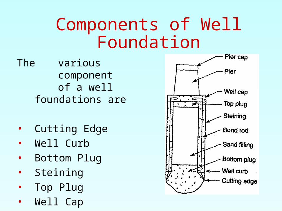
The variouscomponent of a well foundations are
• Cutting Edge• Well Curb• Bottom Plug• Steining• Top Plug• Well Cap

Design of WellsDesign of wells basically involves finding
1. Depth of the well
2. Size of the well and
3. Design of the other components.

Depth of ScourWell foundations are constructed in river beds, they
should be taken to a safe depth well below the anticipated scour level. Scour around piers depends on several factors like flood discharge, the angle of attack of the flow, flow obstruction etc. The scour depth is calculated as follows.
w here
Ds Scourdepth (m)
q Design discharge(m3/s) sf Silt factor 1.76
Dm
Dm Mean diameter of soil particle in river bed (mm)
Ds 0.473
Q
f

Values of Silt Factor
Type of material Mean diameter (mm) sf
Coarse silt 0.04 0.35
Fine sand 0.08 0.5
Fine sand 0.15 0.68
Medium sand 0.3 0.96
Medium sand 0.5 1.24
Coarse sand 0.7 1.47
Coarse sand 1 1.76
Coarse sand 2 2.49
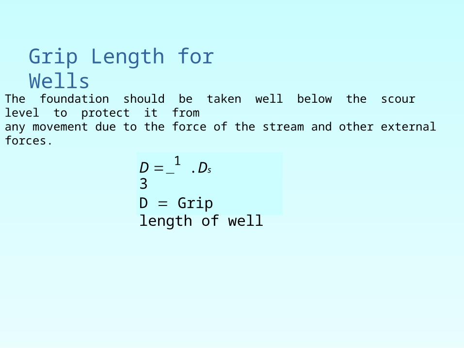
The foundation should be taken well below the scour level to protect it fromany movement due to the force of the stream and other external forces.
D 1 .Ds
3D Grip length of well
Grip Length for Wells
Size of Wells The size of dredge hole of a well
varies. In small and shallow wells, the minimum diameter of the dredge hole should be 1.8 m. In larger wells, the
minimum size of the dredgehole3 m. The final size
is
should bedecided after satisfyingthe
lateralstability condition of the wells.
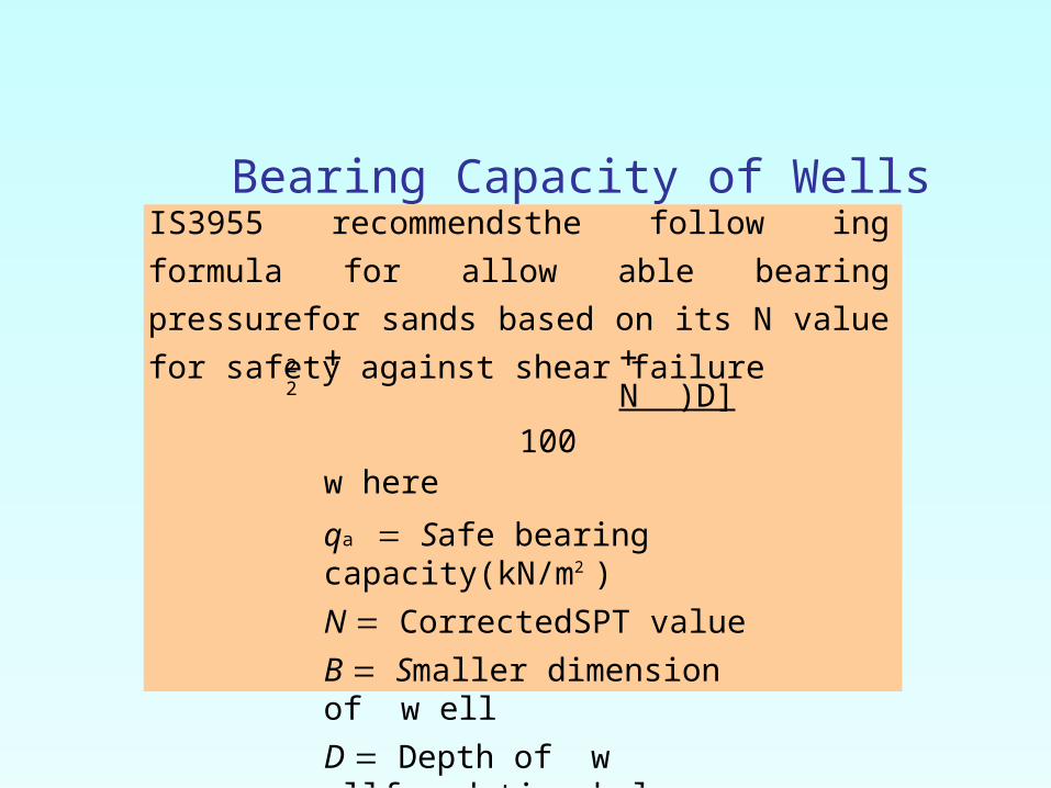
Bearing Capacity of Wells
qa [5.4N B 16(100 N
)D]
100w here
qa Safe bearing capacity(kN/m2 )
N CorrectedSPT value
B Smaller dimension of w ell
D Depth of w ellfoundation below scourlevel
IS3955 recommendsthe follow ing formula for allow
able bearing pressurefor sands based on its N value for
safety against shear failure2 2
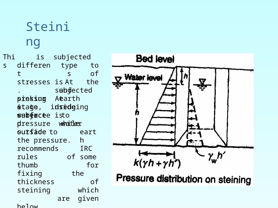
This is subjected toof
thedifferent stresses. sinking it towater
typesAt
is subjectedandearthpressure. At
dredgingstage, inside surface issubjected to
waterpressure while outsidesurface tothe pressure. recommends
earthIRCsomerules of thumb
for fixing the thickness of steining which are given below.
Steining
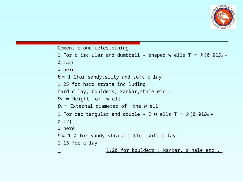
Cement c onc retesteining
1.For c irc ular and dumbbell - shaped w ells T k (0.01DH 0.1De)
w here
k 1.1for sandy,silty and soft c lay
1.25 for hard strata inc luding
hard c lay, boulders, kankar,shale etc .
DH Height of w ell
De External diameter of the w ell
1.For rec tangular and double - D w ells T k (0.01DH 0.12)
w here
k 1.0 for sandy strata 1.1for soft c lay
1.15 for c lay
1.20 for boulders , kankar, s hale etc .
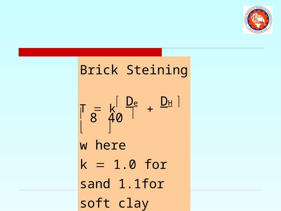
Brick Steining T k
De DH
8 40 w here
k 1.0 for sand
1.1for soft clay
1.25for hard clay
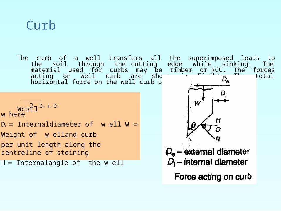
The curb of a well transfers all the superimposed loads to the soil through the cutting edge while sinking. The material used for curbs may be timber or RCC. The forces acting on well curb are shown in Fig(b). The total horizontal force on the well curb on both sides is
Wcot De Di
w here
Di Internaldiameter of w ell W Weight of w
elland curb
per unit length along the centreline of steining
Internalangle of the w ell
2
Curb
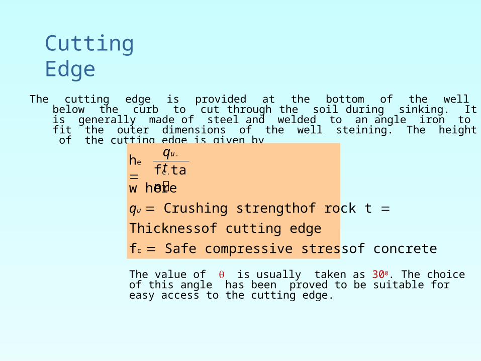
The cutting edge is provided at the bottom of the well below the curb to cut through the soil during sinking. It is generally made of steel and welded to an angle iron to fit the outer dimensions of the well steining. The height of the cutting edge is given by
w here
qu Crushing strengthof rock t Thicknessof cutting edge
fc Safe compressive stressof concrete
The value of is usually taken as 300. The choice of this angle has been proved to be suitable for easy access to the cutting edge.
fc.tan
he
qu.t
Cutting Edge

Bottom Plug
After finalgrounding
ofthewell to the required
foundation level, a concrete plug is provided. The bottom plug transfer the entire load to the ground. The bottom plug functions as an inverted dome supported along the periphery of the steining. As it is not feasible to provide reinforcement at the bottom, it is generally made thick and a rich concrete mix (M20) is used.
Sand Filling
The bottom plug concrete is cured and after curing, the well is filled with sand in saturated condition. Sand filling provides
1. Stability to the bottom of the well.2. Eliminat
ebase
3. Cancels steining
the tensile forces atthe
hoop stressesinduced in

Top Plug
The top plug is provided after the filling is completed. Top plug helps in transferring the load of the pier and superstructure to the steining. The thickness of the top plug is generally kept greater than 50 % of the smaller dimension of the dredge hole. If sand filling is used, the top plug is simply constructed using PCC of 1:2:4 otherwise it is reinforced with steel bars and lean concrete of 1:3:6 is used.
Well Cap
As the shape of the well pier and cap are different, the well cap forms an interim layer to accommodate the pier. The well cap is so designed that the base of the pier is provided with a minimum all round offset. The centre of the well cap is made to coincide with that of the pier and not with that of the well. Such positioning nullifies the effect of the minor shifts which might have occurred during well sinking.

Stability Analysis of Well Foundations
A well foundation supporting a bridge pier is subjected to vertical and horizontal forces. The various forces acting on the well are
• Self weight of the well and its superstructure
• Live loads
• Water currents and buoyancy
• Temperature, wind and earth quake
• Breaking and tracking forces
• Resistance of the well walls
• Base and skin friction
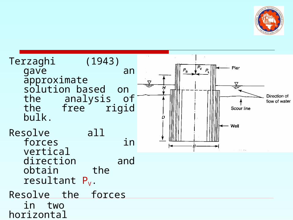
Terzaghi (1943) gave an approximate solution based on the analysis of the free rigid bulk.
Resolve all forces in vertical direction and obtain the resultant PV.
Resolve the forces in two
horizontal directionsi.e along and across
the pier and get the values of PB and PL
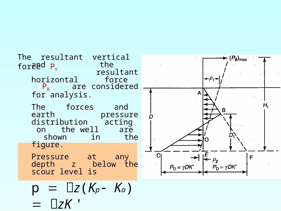
The resultant vertical force PV
and the resultant horizontal force PB are considered for analysis.
The forces and earth pressure distribution acting on the well are shown in the figure.
Pressure at any depth z below the scour level is
p z(Kp Ka) zK '
z DPD DK '

The well is assumed to fail assoon as the soil reaction atthe bottom is equal to
PD. For equilibrium at that instant(PB) m ax resultant of total pressureper unit length
area of AEF - area of BCF
1 D2 K ' 1 2DK ' D1
Solving for D1
2D1 3H 1 9H 2 1
2D(3H 1 D)
(2)2 3 2 3
(PB) m ax H 1 1 D2 K ' D 1 2DK ' D D
11
(PB) m ax 1 DK '(D 2D1)2
Taking moment about E
(1)
2 2or
Putting D1 in equation (1) and solving for D. This D
is the grip length required to sustain the maximum
horizontal force.
A safe depth can be obtained by reducing PD by a
factorof safety F.This theoryis based on follow ing
assumptions
1.The w ellis treated as a light bulk head
2.KP and Ka are Rankine' s earth pressurecoefficients
3.Thereis no friction at the base and w all
Omision of thesefrictional forcesyields a
conservative (PB)m ax.
If 1 and 2 are the horizontal displacements, then
theangular deflection of the centrelineof the w ell, is given as
tan 1 (1 2)D
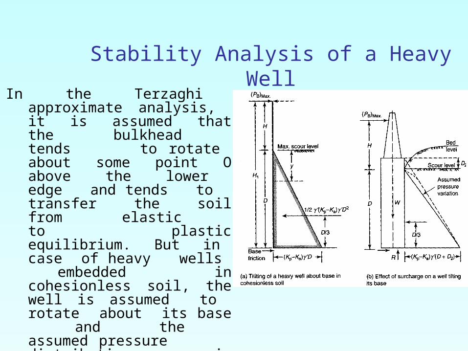
Stability Analysis of a Heavy WellIn the Terzaghi approximate
analysis, it is assumed that the bulkhead tends to rotate about some point O above the lower edge and tends to transfer the soil from elastic to plastic equilibrium. But in case of heavy wells embedded in cohesionless soil, the well is assumed to rotate about its base and the assumed pressure distribution is given in Fig(a). Taking the moment about the base, the value of (PB)max

1 D3
(PB) m ax '(KP Ka)6 H DNormally around the w ell, scouring takes place.
Beyond the w ellsurroundings, the
uncovered soil acts as a surcharge.The
surchargedepth D2 is verydifficult to
assessand may be assumed to be equal to
half the normaldepth of scour.The
pressuredistribution is shownin
Fig(b).The
equivlant maximum resistanceforceis then given as1 D2 (D D2)(PB) m ax ' K '6 H D

If d is the diameter or length of the w ell, the total
resisting forceafter allow ing a factorof safety,F is
given as
Pa ( PB ) m a x d
FThe factorof safetyshould not be less than 2.
The maximum pressuref at the base of the
w ell for theno overturning moment condition is
f W
Aw here
W is the net direct load on the w ell base after
making allow ancefor buoyancy and skin friction
A Area of w ell base
z section modulus of the w ell base The
maximum foundation pressure
should be kept w ithin thesafe bearing capacity
of the soil assuming no tension occursat the base.
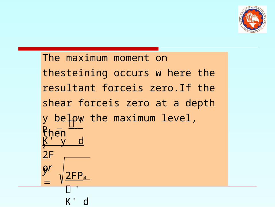
2FPa
' K' d
Pa ' K' y
d
2For
The maximum moment on thesteining occurs
w here the resultant forceis zero.If the shear
forceis zero at a depth y below the maximum
level, then2
y
IRC and IS Design Recommendations
The IRC and IS 3955 publications recommend the following procedure for design of well foundations in sand deposits (for clay the expressions should be suitably modified)
1 Check the stability of well under working loads, assuming elastic theory
2. Find the factor of safety of thewell againstultimate failure using ultimate load theory

Causes of Tilts and Shifts1. Nonuniform bearing capacity2. Obstruction on one side of the well3. Sand blowing in wells during sinking. It will cause
sudden sinking of well4. Method of sinking: Material should be removed from
all sides equally otherwise the well may experience tilt
5. Sudden sinking due to blasting may also cause tilting of well
6. Irregular casting of steining will cause less friction onone side leads to chances of tilting of well.

Rectification of Tilt1. Eccentric grabbing2. Eccentric loading3. Water jetting4. Arresting the cutting edge5. Pulling the well6. Strutting the well7. Pushing the well by jacks