welding normatives protocols
DESCRIPTION
Methods of welding and provisions.TRANSCRIPT

NCSX
Design Basis Analysis
Welded Joint FDR
NCSX-CALC-14-005-00
20 November 2007
Prepared by:
_______________________________________
K. Freudenberg, ORNL
I have reviewed this calculation and, to my professional satisfaction, it is properly performed and correct. I concur with analysis methodology and inputs and with the reasonableness of the results and their interpretation.
Reviewed by:
_______________________________________
David Williamson, ORNL
Controlled DocumentTHIS IS AN UNCONTROLLED DOCUMENT ONCE PRINTED.
Check the NCSX Engineering Web prior to use to assure that this document is current.

NCSX-CALC-14-005-00
Record of Revisions
Revision Date Description
0 11/20/2007 Initial Issue
Table Of Contents
1. Executive Summary....................................................................................................................................1
2. Introduction................................................................................................................................................2
3. Analysis Approach......................................................................................................................................2
3.1. Material Properties...............................................................................................................................4
3.2 Magnetic Loading...................................................................................................................................4
3.3. Assumptions...........................................................................................................................................4
3.4. Allowable weld stress (static)................................................................................................................7
4. Global Model Results...............................................................................................................................10
4.1 AA Global Model with weld.................................................................................................................10
4.2. AB Global Model with weld................................................................................................................15
4.3. BC Global Model with.........................................................................................................................19
4.3. Tabular results for the global runs......................................................................................................23
5. Special analysis runs.................................................................................................................................23
5.1. AB weld Submodel...............................................................................................................................23
5.1. AB Middle shim redesign.....................................................................................................................26
5.3. Including the bolts on the AB Interface...............................................................................................29
6. Fatigue Study Courtesy I. Zatz PPPL..................................................................................................32
7. Conclusion.................................................................................................................................................34
References.....................................................................................................................................................34
A. Attachments.............................................................................................................................................35
A.1 Bonded Interfaces................................................................................................................................35
A.2. Letting the inboard leg slip.................................................................................................................40
A.3. Directional Stress slides used in fatigue study...................................................................................43
i

NCSX-CALC-14-005-00
Table Of FiguresFIG. 1. MOD COIL SCHEMATIC SHOWING THE WINDING CAVITY (TEE), WINDING AND
CLAMPS..................................................................................................................................................2
FIG. 2. FULL PERIOD COIL CAD MODEL (6 COILS)..............................................................................3
FIG. 3. OVERVIEW OF MODULAR COIL ASSEMBLY INDICATING GENERAL WELD LOCATIONS...........................................................................................................................................3
FIG. 4. HALF-FIELD PERIOD GLOBAL ANSYS MODEL.........................................................................5
FIG. 5. CONSTRAINT EQUATION SYMBOLS AT A-A SHIM MID-THICKNESS.................................6
FIG. 6. NODAL FORCES (T=0.0S OF 2T, HIGH-b).....................................................................................6
FIG. 7. PROE MODEL OF THE ACTUAL WELD SHIMS FOR THE AA INTERFACE SHOWING BOTH FLANGE INTERFACES...........................................................................................................12
FIG. 8. ANSYS MODEL OF THE WELD AND WELD SHIMS ON THE GLOBAL MODEL FOR AA.................................................................................................................................................................12
FIG. 9. SLIDING ON THE SHIM/FLANGE INTERFACE.........................................................................13
FIG. 10: STRESS INTENSITY OF THE AA WELDED SHIM (GLOBAL MODEL)................................13
FIG. 11. WELD STRESS INTENSITY OF THE AA FLANGE (GLOBAL MODEL)...............................14
FIG. 12. COMPRESSIVE STRESS OF THE AA PUCKS (GLOBAL MODEL)........................................14
FIG. 13. COMPRESSIVE STRESS OF THE AA PUCKS WITH THE AMOEBA PUCK (GLOBAL MODEL).................................................................................................................................................15
FIG. 14. PROE MODEL OF THE ACTUAL WELD SHIMS FOR THE AB SHIM ON TYPE B COIL. . .16
FIG. 15. ANSYS MODEL OF THE WELD AND WELD SHIMS ON THE GLOBAL MODEL FOR AB................................................................................................................................................................16
FIG. 15. GLOBAL DEFLECTION OF B CASTING WITH THE AB WELD...........................................17
FIG. 16. SLIDING ON THE SHIM/FLANGE AB INTERFACE................................................................17
FIG. 17. STRESS INTENSITY OF THE AB WELDED INTERFACE (GLOBAL MODEL)....................18
FIG. 18. STRESS INTENSITY ON THE AB SHIM AND COMPRESSIVE STRESS ON THE PUCKS.18
FIG. 19. PROE MODEL OF THE ACTUAL WELD SHIMS FOR THE BC SHIM ON TYPE C COIL....20
FIG. 20. ANSYS MODEL OF THE WELD AND WELD SHIMS ON THE GLOBAL MODEL FOR BC.................................................................................................................................................................20
FIG. 21. GLOBAL DEFLECTION ON THE C CASTING FOR THE FLANGE BC WELD MODEL.....21
FIG. 22. SLIDING ON THE SHIM/FLANGE BC INTERFACE................................................................21
FIG. 23: STRESS INTENSITY FOR THE A) WELD, B) PUCKS, AND C) SHIMS FOR THE BC WELD MODEL..................................................................................................................................................22
FIG. 24: STRESS INTENSITY FOR THE BC FLANGE INNER LEG WELD REGION AND A CLOSE UP VIEW OF THE PEAK WELD AND SHIM STRESSES................................................................22
FIG. 25. REPREHENSIVE CUTOUT OF THE BC COIL SHOWING THE MESH REFINEMENT NEAR THE WELD............................................................................................................................................24
FIG. 26 WELD AND SHIM ELEMENTS AND THE CUT BOUNDARIES OF A SUBMODEL.............24
FIG. 27: STRESS INTENSITY OF THE SHIM AND WELD FOR THE AB SUBMODEL......................25
ii

NCSX-CALC-14-005-00
FIG. 28: STRESS INTENSITY OF THE SHIM AND WELD COMPARED TO THE MAX STRESS SEEN IN THE GLOBAL MODEL........................................................................................................26
FIG. A.1-1 SUBDIVISION OF A-A INBOARD LEG AND INTEGRATED SHEAR STRESSES............35
FIG. A.1-2 SUBDIVISION OF A-B INBOARD LEG (SIMILAR TO A-A) AND INTEGRATED SHEAR STRESSES.............................................................................................................................................37
FIG. A.1-3 SUBDIVISION OF B-C INBOARD LEG (SIMILAR TO A-A) AND INTEGRATED SHEAR STRESSES.............................................................................................................................................38
FIG. A.1-4 SUBDIVISION OF C-C INBOARD LEG (SIMILAR TO A-A) AND INTEGRATED SHEAR STRESSES.............................................................................................................................................39
FIG A.2.1. SLIPPAGE AND SHEAR BOLT LOADING ON AA IF THE INNER LEG RIDES ON A FRICTIONLESS SURFACE.................................................................................................................40
FIG A.2.2. SLIPPAGE AND SHEAR BOLT LOADING ON AB IF THE INNER LEG RIDES ON A FRICTIONLESS SURFACE.................................................................................................................41
Fig A.2.3. Slippage and shear bolt loading on BC if the inner leg rides on a frictionless surface................42
iii
NCSX-CALC-14-005-00
1. Executive Summary
A structural analysis of the NCSX Modular Coil (MC) assembly field period welding is presented. The
analysis focuses on the inboard coil-to-coil welded connections (so-called A-A, A-B, and B-C) in an effort
to determine the acceptability of these welded joints. The CC connection still requires electrical insulation
and will use added in-board bolts instead of welding and is not addressed in this document. The analysis is
based on an evolutional global ANSYS [1] model of the A-B-C half-field period [2], and various sub-
models of the weld zones near the flange interfaces. The adopted welding technique uses an alternating
MIG fillet weld on each side of the shim between coil castings to react the shear loads while compressive
pucks located in the middle of the shim react the compressive loads. By welding the shim from both sides,
distortion is minimized and the welded shim no longer carries tension as it did in the previous "front nose
only" weld configuration. The global model uses a courser mesh (roughly 2 X 2 elements per weld cross-
section) on and near the weld region to capture the gross deformations and stresses of the flange interfaces.
Each weld analysis is performed as a separate global or sub-model with one weld being examined at a time.
Also, the sub-model includes details such as shim segmentation and decreased shim thickness, which are
not able to be produced on the global model due to their geometric sizing.
Further, a separate analysis is presented that shows the impact of the welds and bolts operating together in
one package. To date, the two analysis runs have been mutually exclusive in that the weld study assumed a
bonded outboard condition and the bolt study considered a range of frictional values on the inboard leg.
The latter bolt model described in DAC # 006 [3] is conservative because the weld will undoubtedly
provide for a stiffer connection than that of the modest friction range studied (0 -0.4). However,
approximating the outboard bolted region as strictly bonded was thought to be slightly non-conservative
and thus, the two studies were augmented and merged for the AB flange. After comparison between the
AB flange models, it is determined that including the bolts does not significantly effect the deflections or
stress results of the welded flange and the approximation of bonding the outboard region when studying the
welds is valid.
All of the analysis to data shows that a 7/16" fillet weld is sufficient to carry the shear across the interfaces
statically. The average stress through the welds is between 13-18 ksi, below the static limit of 24 ksi. The
2" compressive pucks are also adequately designed to handle the compressive load through the flanges
having average stresses less than 20 ksi. Further, the shims stresses are acceptable and have averages
ranging from 17 to 34 ksi with the largest stress occurring on one shim on the AB interface. The allowable
membrane for the shim material (316L) is 39 ksi. Using smaller diametric holes (1.6" vs 2.1") on the one
AB shim reduces the stress range to 17 to 24 ksi and provides more margin on the allowable. This design
change uses smaller holes on one shim has been adopted.
1

NCSX-CALC-14-005-00
2. Introduction
The function of the NCSX modular coil system is 1) to provide specified quasi-axisymmetric magnetic
field configurations, 2) to provide access for tangential neutral beam injection (NBI), radio frequency (RF)
heating, and diagnostics, and 3) to provide a robust mechanical structure that minimizes non-symmetric
field errors. The coil set consists of three field periods with six coils per period, for a total of 18 coils. Due
to stellarator symmetry, only three different coil shapes are needed to make up the complete coil set. The
coils are connected electrically in three circuits according to type, and as such can produce alternate
magnetic configurations by independently varying the current for each type.
The modular coils are wound onto stainless steel castings that are then bolted together to form a structural
shell. As shown in Fig. 1, the winding cavity is a “tee” structure that is located on and integral with the
plasma side of the shell. During operation, electromagnetic forces push the windings outward against the
shell and laterally toward the “tee”, so that only intermittent clamps are required for structural support.
Fig. 1. Mod Coil Schematic showing the winding cavity (tee), winding and clamps
3. Analysis Approach
A CAD model of the MC half-field period assembly is shown in Fig. 2 and provides an overview of the
modeling scope. This incarnation of the model represents the latest version of the model complete with
individual shims, bolts and inner leg weld shims. This CAD version does not include any inboard bolt
holes (previous design) on the AA, AB and BC flanges but holes have been added to the CC Flange. Fig. 3
illustrates a detailed look at the bolt/shim/flange of the weld regions for the AA, AB and BC flanges.
2

NCSX-CALC-14-005-00
Fig. 2. Full Period Coil CAD Model (6 Coils)
5 welds/period (typ.) in central region.
5 welds/period (typ.) in central region.
Fig. 3. Overview of modular coil assembly indicating general weld locations.
3

NCSX-CALC-14-005-00
3.1. Material Properties
The properties (listed in Table 1) assume that the shell is made of stainless steel and the coil windings
consist of a homogeneous copper/epoxy mixture. These values are used when the thermal loading from a
localized modular coil model is applied to the shell and the winding form. The weld material has the same
material properties as the Tee/shell in the analysis. The cte values are not used in this particular form of the
analysis as no thermal loading is applied. Also, the clamp and top clamp pad are not included here either.
The purpose of the clamps and pads was to access the deflection characteristic of the winding packs as the
winding were allowed to slide and release from the casting in the non-linear model a few years back.
TABLE 1: Material Properties.
3.2 Magnetic Loading
Calculations to determine the fields and forces acting on all of the stellarator core magnets have been
completed for seven reference operating scenarios. The worst case for determining forces in the modular
coils appears to be the 2T high beta scenario at time=0.197-s. Two independent field calculations have
been performed, one with the ANSYS code and the other with MAGFOR [4]. A comparison of magnetic
flux density at 2-T indicates that the models are in good agreement, with only a 4% difference in peak field
due primarily to mesh and integration differences.
3.3. Assumptions
Due to the resulting high element count when attempting to model a full period (6 coil) with a reasonable
mesh, a half period model was adopted at the analysis inception in 2004. This half period (3 coil) model is
shown in Fig. 4. Simulating the 12-coil MC system with a half-field period model requires the application
of displacement U(R,θ,Z) constraint equations (CE) to the cut boundaries (θ=0º & 60º). Nodes on these
symmetry planes are rotated into a cylindrical coordinate system. Fig. 5 shows a graphical representation
of this boundary condition which illustrates the following general rule. The vertical lines represent the link
between the +Z nodes and -Z nodes. One node on the B shell is restrained in the vertical direction (z) to
complete the required DOF constraints.
4

NCSX-CALC-14-005-00
UR(R,θ,Z) = +UR(R,θ,-Z)Uθ(R,θ,Z) = -Uθ(R,θ,-Z)UZ(R,θ,Z) = -UZ(R,θ,-Z)
The electromagnetic loading (EM) is limited to one particular time-point (t=0.0s) within one particular
current scenario (2T High-b). It is commonly thought that this represents the worst load case. However,
there has been no attempt to verify this position. The nodal force files for each coil are read into the
structural routine before the solution. Fig. 6 shows a plot of the coils and nodal force vectors (for
visualization purposes).
Previous analysis [2,5] has shown that the non-linear contact interactions between the coils and winding
forms do have an impact on stress. Running a non-linear sliding winding in this case is computationally
difficult given the compute time required. Thus, to simulate this effect in a linear manner, a "wimpy"
winding pack was used in these models. It has a modulus of 856 Mpa or 100 times less than that listed in
Table 1. This allows for the brunt of the magnetic loading to transfer directly to the tee as the winding pack
stiffness is reduced. This has a greater effect near the tee region than the flange interfaces but to be
conservative, the value was used to simulate the maximum amount of magnetic loading the shell would
ever experience.
Fig. 4. Half-Field Period Global ANSYS Model.
Model Boundaries in a cylindrical coordinate system are at:θ=0º (mid-thickness A-A shim)
θ=60º (mid-thickness C-C shim)
5

NCSX-CALC-14-005-00
Fig. 5. Constraint Equation Symbols at A-A Shim Mid-Thickness
Fig. 6. Nodal Forces (t=0.0s of 2T, High-b)
3.4. Allowable weld stress (static)
6

NCSX-CALC-14-005-00
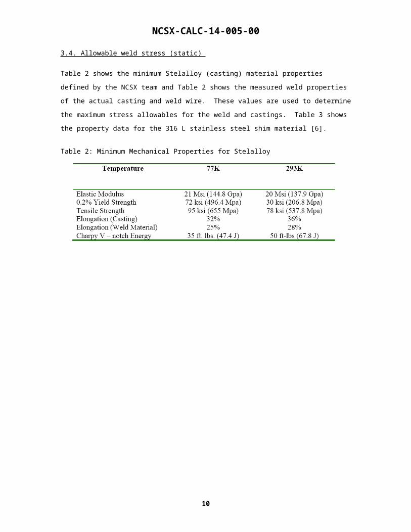
Table 2 shows the minimum Stelalloy (casting) material properties defined by the NCSX team and Table 2
shows the measured weld properties of the actual casting and weld wire. These values are used to
determine the maximum stress allowables for the weld and castings. Table 3 shows the property data for
the 316 L stainless steel shim material [6].
Table 2: Minimum Mechanical Properties for Stelalloy
7

NCSX-CALC-14-005-00
Table 3: Measured properties of Actual castings and weld wire.updated 2/15/07
AVERAGES Type CCasting
ComparisonProperty Required C1 C2 C3 C4 C5 C6 Required C1 C2 C3 C4 C5 C6
Elastic Modulus
21 Msi (144.8 Gpa)
23.3 25.5 24.9 26.5 30.2 28.8 20 Msi (137.9 Gpa)
23.1 22.7 21.6 23.1 27.3 24.1
0.2% Yield Strength
72 ksi (496.4 Mpa)
98.4 93.2 97.1 97.8 102.5 99.5 34 ksi (234.4 Mpa)
35.1 36.6 38.3 37.4 38.8 44.5
Tensile Strength
95 ksi (655 Mpa)
170.3 163.8 163.1 164.8 170.9 159.9 78 ksi (537.8 Mpa)
83.7 82.4 82.7 83.1 87.0 83.7
Elongation 32.0% 55.7% 54.3% 55.7% 54.0% 42.4% 42.3% 36.0% 52.0% 53.5% 52.5% 55.7% 58.0% 40.3%Charpy V – notch Energy
35 ft. lbs. (47.4 J)
77.7 84.3 99.7 86.7 80.3 85.3 50 ft-lbs (67.8 J)
142.0 150.7 157.3 175.7 139.0 152.3
Type ACasting
ComparisonProperty Required A-1 A-2 A-3 A-4 A-5 A-6 Required A-1 A-2 A-3 A-4 A-5 A-6
Elastic Modulus
21 Msi (144.8 Gpa)
25.5 25.3 26.7 28.9 26.4 27.9 20 Msi (137.9 Gpa)
21.7 22.2 21.9 22.9 23.1 22.6
0.2% Yield Strength
72 ksi (496.4 Mpa)
97.3 99.9 98.9 100.0 101.0 103.2 34 ksi (234.4 Mpa)
36.6 43.3 43.2 43.8 42.4 44.5
Tensile Strength
95 ksi (655 Mpa)
166.3 165.3 166.0 165.9 165.2 163.0 78 ksi (537.8 Mpa)
82.4 83.7 82.6 84.6 82.2 89.2
Elongation 32.0% 56.0% 56.3% 51.0% 46.0% 48.7% 38.3% 36.0% 53.2% 56.0% 53.3% 50.3% 50.0% 49.0%Charpy V – notch Energy
35 ft. lbs. (47.4 J)
78.7 79.0 87.3 76.7 70.3 73.0 50 ft-lbs (67.8 J)
163.7 164.0 158.0 150.3 146.3 126.7
Type B
Casting Compariso
nProperty Required B-1 B-2 B-3 B-4 B-5 B-6 Required B-1 B-2 B-3 B-4 B-5 B-6
Elastic Modulus
21 Msi (144.8 Gpa)
25.9 27.4 29.3 25.3 29.3 20 Msi (137.9 Gpa)
22.7 22.5 22.6 22.8 22.6
0.2% Yield Strength
72 ksi (496.4 Mpa)
98.7 103.9 107.4 100.2 107.4 34 ksi (234.4 Mpa)
43.3 58.9 42.7 42.6 42.7
Tensile Strength
95 ksi (655 Mpa)
164.9 177.5 172.5 166.1 177.5 78 ksi (537.8 Mpa)
86.0 86.6 84.1 85.6 84.1
Elongation 32.0% 46.3% 50.3% 56.3% 53.3% 56.3% 36.0% 47.3% 49.5% 44.7% 43.5% 44.7%Charpy V – notch Energy
35 ft. lbs. (47.4 J)
88.0 63.7 74.7 65.7 74.7 50 ft-lbs (67.8 J)
146.7 135.7 115.0 119.7 115.0
Weld MaterialProperty Required Lincoln
3018926/78309
Lincoln Lot #
3012668/82743
Lincoln 3018513/7
8308
Lincoln Lot #
3017006/72262
Metrode Lot #
WO21735
Metrode Lot #
WO19711
Required Lincoln 3018926/78309 Doc
#10
Lincoln Lot #
3012668/82743 see previous info ->
Lincoln 3018513/7
8308
Lincoln Lot #
3017006/72262
Metrode Lot #
WO21735
Metrode Lot #
WO19711
Previously Reported
Heat/Lot # 3012668/8
2743
Elastic Modulus
21 Msi (144.8 Gpa)
23.3 27.1 Doc#9
27 23.2 24.3 26.4 Doc#9
20 Msi (137.9 Gpa)
24.5 Doc 10
22.6 23.4 24.9 23 23.1 Doc#10
25.5 Doc#10
0.2% Yield Strength
72 ksi (496.4 Mpa)
114.3 126.3 Doc#9
128.2 112.4 102.1 109.5 Doc#9
34 ksi (234.4 Mpa)
56.9 Doc #10
57.4 65.2 54.9 54.8 63.9 Doc#10
56.5 Doc#10
Tensile Strength
95 ksi (655 Mpa)
157.5 187.7 Doc#9
182.1 176.4 166.6 166.9 Doc#9
78 ksi (537.8 Mpa)
93.9 Doc #10
93.7 95.2 92.1 88.2 98.1 Doc#10
85 Doc#10
Elongation 32% 16.0% 33% Doc#9
34.0% 48.0% 38.0% 34% Doc#9
36.0% 42% Doc #10
41.5% 38.0% 42.5% 37.5% 54% Doc#10
55% Doc#10
Charpy V – notch Energy
35 ft. lbs. (47.4 J)
36.33 51 Doc#11
54 53 48 48 Doc#11
50 ft-lbs (67.8 J)
100 Doc #10
98 103 117 93 111 Doc#12
102 Doc#12
77K (-320F) 293K (RT)
77K (-320F) 293K (RT)
77K (-320F) 293K (RT)
77K (-320F) 293K (RT)
Table 4: Low temperature property data for 316L and 31LN stainless steel. (Vogt)
8

NCSX-CALC-14-005-00
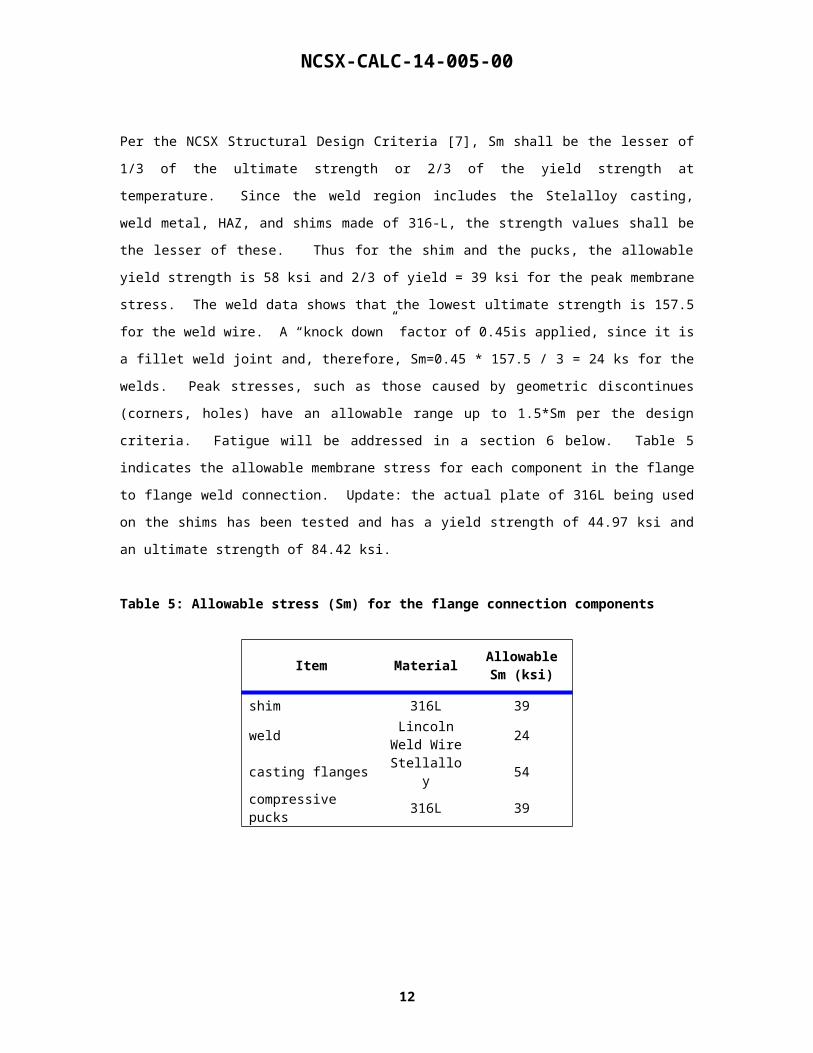
Per the NCSX Structural Design Criteria [7], Sm shall be the lesser of 1/3 of the ultimate strength or 2/3 of
the yield strength at temperature. Since the weld region includes the Stelalloy casting, weld metal, HAZ,
and shims made of 316-L, the strength values shall be the lesser of these. Thus for the shim and the pucks,
the allowable yield strength is 58 ksi and 2/3 of yield = 39 ksi for the peak membrane stress. The weld data
shows that the lowest ultimate strength is 157.5 for the weld wire. A “knock down” factor of 0.45is
applied, since it is a fillet weld joint and, therefore, Sm=0.45 * 157.5 / 3 = 24 ks for the welds. Peak
stresses, such as those caused by geometric discontinues (corners, holes) have an allowable range up to
1.5*Sm per the design criteria. Fatigue will be addressed in a section 6 below. Table 5 indicates the
allowable membrane stress for each component in the flange to flange weld connection. Update: the actual
plate of 316L being used on the shims has been tested and has a yield strength of 44.97 ksi and an ultimate
strength of 84.42 ksi.
Table 5: Allowable stress (Sm) for the flange connection components
Item MaterialAllowable Sm
(ksi)
shim 316L 39
weldLincoln
Weld Wire24
casting flanges Stellalloy 54
compressive pucks 316L 39
9

NCSX-CALC-14-005-00
4. Global Model Results
4.1 AA Global Model with weld
The weld shim layout for the AA coil interface is shown in Fig. 7. The green shims represent those that are
to welded on the A1 coil while the purple shims are welded to the adjacent a coil (A2). The shims attached
to the flanges in the figure are welded on their backside to the mating surface. The weld itself is segmented
by the shims and 0.25" gaps spaced every 4 inches along the weld. The purpose of alternating the welding
shims in connecting across the flange is to prevent distortion of the structure during welding. The weld
types are MIG fillets whose throat size is 0.3" and the length is approximately 3" between breaks..
The finite element global model for the AA interface is shown in Fig 8. The weld is represented by a
rectangular hex mesh in all of the global model runs and it is not segmented. The shim area immediately
next to the weld and extending up and down to the first bolt has no contact connecting to the flange since
the shim is thinner than the gap between flanges. The shim covering the bolted areas is set to bonded
contact. This behavior is appropriate since previous analysis [3] has shown that the bolts do not slip over
this region as the preload and high friction coating maintain the interfaces in a "stuck" condition. Further, a
study of the ab joint with welding and bolts is shown and is documented below in Section 5.3. Since the
AA interface lies on a "cut boundary" in the FEA model, the weld and shims were actually modeled as
extending out 0.25" from the flange surface and constraint equations were written to the half modeled weld
and shim. Care was also taken to match the appropriate weld above and below the symmetry line. Sub-
modeling this weld would be difficult due to this issue.
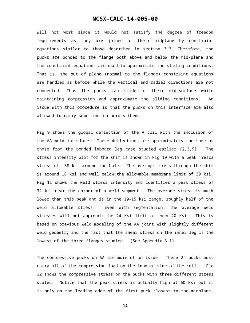
Further, this flange requires a different set up for the compression pucks than the others. Simply letting
them slide on the flange surface will not work since it would not satisfy the degree of freedom requirements
as they are joined at their midplane by constraint equations similar to those described in section 3.3.
Therefore, the pucks are bonded to the flange both above and below the mid-plane and the constraint
equations are used to approximate the sliding conditions. That is, the out of plane (normal to the flange)
constraint equations are handled as before while the vertical and radial directions are not connected. Thus
the pucks can slide at their mid-surface while maintaining compression and approximate the sliding
conditions. An issue with this procedure is that the pucks on this interface are also allowed to carry some
tension across them.
Fig 9 shows the global deflection of the A coil with the inclusion of the AA weld interface. These
deflections are approximately the same as those from the bonded inboard leg case studied earlier [2,3,5].
The stress intensity plot for the shim is shown in Fig 10 with a peak Tresca stress of 38 ksi around the
hole. The average stress through the shim is around 18 ksi and well below the allowable membrane limit of
39 ksi. Fig 11 shows the weld stress intensity and identifies a peak stress of 32 ksi near the corner of a
weld segment. The average stress is much lower than this peak and is in the 10-15 ksi range, roughly half
10
NCSX-CALC-14-005-00
of the weld allowable stress. Even with segmentation, the average weld stresses will not approach the 24
Ksi limit or even 20 Ksi. This is based on previous weld modeling of the AA joint with slightly different
weld geometry and the fact that the shear stress on the inner leg is the lowest of the three flanges studied.
(See Appendix A.1).
The compressive pucks on AA are more of an issue. These 2" pucks must carry all of the compression load
on the inboard side of the coils. Fig 12 shows the compressive stress on the pucks with three different
stress scales. Notice that the peak stress is actually high at 60 ksi but it is only on the leading edge of the
first puck closest to the midplane. The other noticeable characteristic is that some of the pucks are showing
tension on one of their sides. This is due to a modeling approach which can only be altered if a full period
assembly is modeled instead of the half-period approach taken here. The pucks are placed near the
compression interface between the two flanges but some of them are farther away than others. It is these
pucks that are placed off the direct load path that are being squeezed on the leading edge. Thus, they can
carry some minimal amount of tension on the backside edge. Still, the total force reacted by the puck
across the flange (with or without tension) must be the same, so the peak compression stress on these pucks
can be no greater than that shown. Unfortunately the pucks that see the highest stress near the mid plane
are compression only pucks and the main problem here is simply distribution. That is, more area is needed
to react the load.
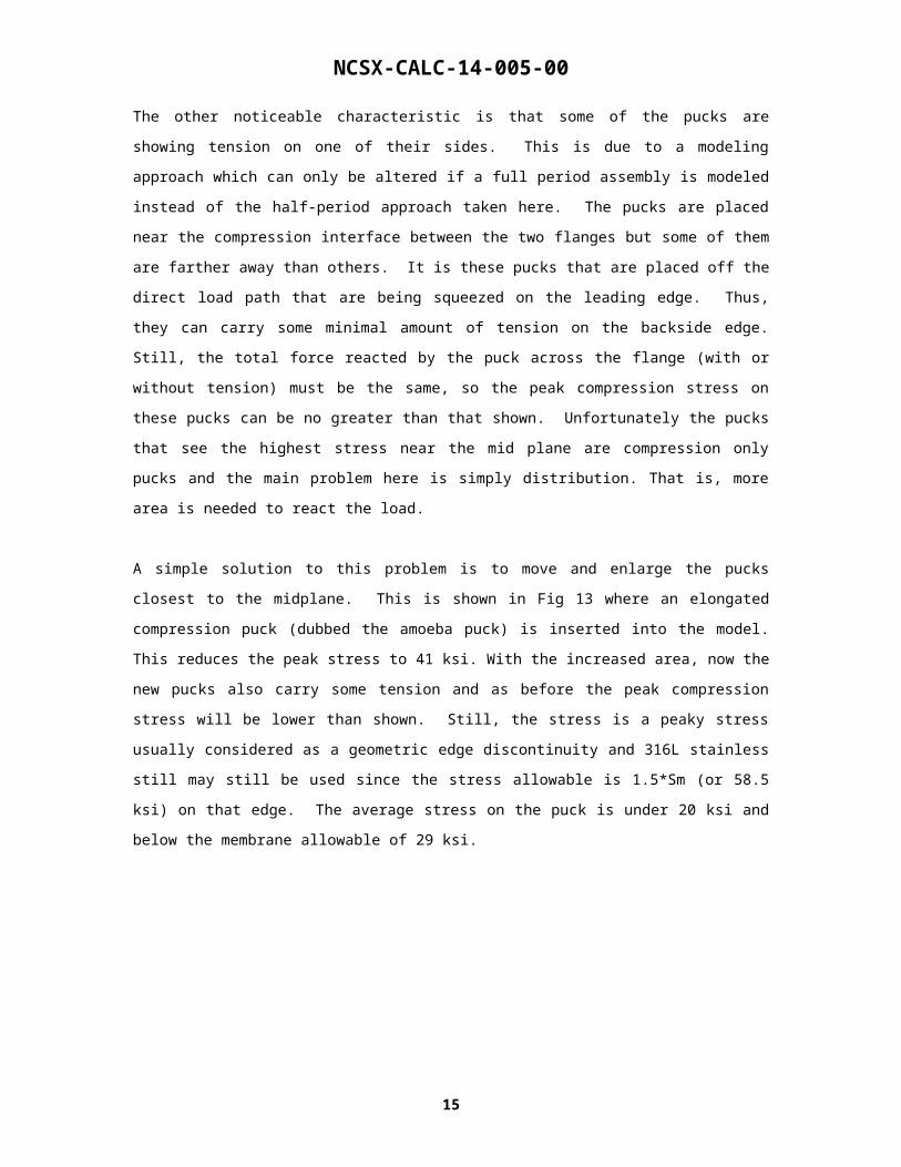
A simple solution to this problem is to move and enlarge the pucks closest to the midplane. This is shown
in Fig 13 where an elongated compression puck (dubbed the amoeba puck) is inserted into the model. This
reduces the peak stress to 41 ksi. With the increased area, now the new pucks also carry some tension and
as before the peak compression stress will be lower than shown. Still, the stress is a peaky stress usually
considered as a geometric edge discontinuity and 316L stainless still may still be used since the stress
allowable is 1.5*Sm (or 58.5 ksi) on that edge. The average stress on the puck is under 20 ksi and below
the membrane allowable of 29 ksi.
11

NCSX-CALC-14-005-00
Fig. 7. ProE model of the actual weld shims for the AA interface showing both flange interfaces.
Fig. 8. Ansys model of the weld and weld shims on the global model for AA.
12
Type A1Type A2
NCSX-CALC-14-005-00
Fig. 9. Sliding on the shim/flange interface
Fig. 10: Stress Intensity of the AA welded shim (global model)
13
Small localized stress which can go to 1.5*Sm where Sm is 39 ksi for 316L.

NCSX-CALC-14-005-00
Fig. 11. Weld Stress Intensity of the AA flange (global model)
Fig. 12. Compressive Stress of the AA pucks (global model)
14
Small peaky stress (no big deal) Stress Rescaled to max of
20 ksi. (very small end effects exceed this value.)
NCSX-CALC-14-005-00
Fig. 13. Compressive Stress of the AA pucks with the amoeba puck (global model)
4.2. AB Global Model with weld
The weld shim layout for the AB coil interface is shown in Fig. 14. The green shims represent those that
are to welded on the B coil while the purple shims are welded to the adjacent A coil. The shims attached to
the flanges are welded on their backside to the flange surface on each of the respective coils.. The weld
itself is segmented by the shims gaps and by 0.25" gaps every 4 inches. The latter gaps are only modeled
in the sub-models and not the global model. The weld types are fillets whose throat size is 0.3" and the
length is approximately 3" between breaks..
The finite element global model for the AB interface is shown in Fig 15. The weld is represented by a
rectangular hex mesh in all of the global model runs and it is not segmented. The shim area immediately
next to the weld and extending up and down to the first bolt has no contact elements present as the shim is
thinner (7/16") than the gap between flanges. Thus, the shim only carries shear and no compression. The
shim covering the bolted areas is set to bonded contact. The pucks are bonded to the A flange but are
allowed to slide (keyopt 12 = 0) on the adjacent B flange. Thus, they can carry compression (no tension)
and allowed to slide. The pucks do not interface with the shims in the analysis and they are not able to
react shear. This is conservative since any shear the pucks do react will subtract from the weld shear and
lower the weld stresses.
Fig 15 shows the global deflection of the A coil with the inclusion of the AA weld interface. These
deflections are approximately the same as those from the bonded inboard leg case studied earlier [2,3,5].
Fig 16 shows the sliding contact interface and status plots for the AB shim. Peak sliding of only 0.2 mm
occurs on one of the pucks. The contact status plot indicates that the pucks are stuck to the A surface as
15
Y stress (normal to flange) psiStress Intensity (psi)
Elongated compressive plug
NCSX-CALC-14-005-00
designed. The stress intensity plot for the weld is shown in Fig. 17 with a peak Tresca stress of 31.5 ksi.
This peak occurs on the corner of a weld and is treated as a geometric edge discontinuity which is
anomalous. The average stress through the weld is 18 ksi, which is lower than the allowable but higher
than the AA weld stress. Since the average stress is approaching 20 ksi and the peak stress is 31.5 ksi at a
corner with a relativity coarse mesh with no segmentation, a more detailed submodel is warranted for this
interface.
Fig. 18 shows the shim stresses and the puck compression stresses for the AB interface. The stress intensity
for the weld has a peak of 39 ksi around the hole. The average stress through the shim is approximately 34
ksi near this peak stress but still under the allowable limit of 39 ksi (316 L). The AB average shim stress is
the highest of the three analysis models (AA,AB and BC) and is the subject of a design change documented
below in section 5.2. The average stress in the shim may be lowered by reducing the size of the puck hole
and/or by slightly moving the hole pattern. The peak shim stress is a hole stress discontinuity and therefore
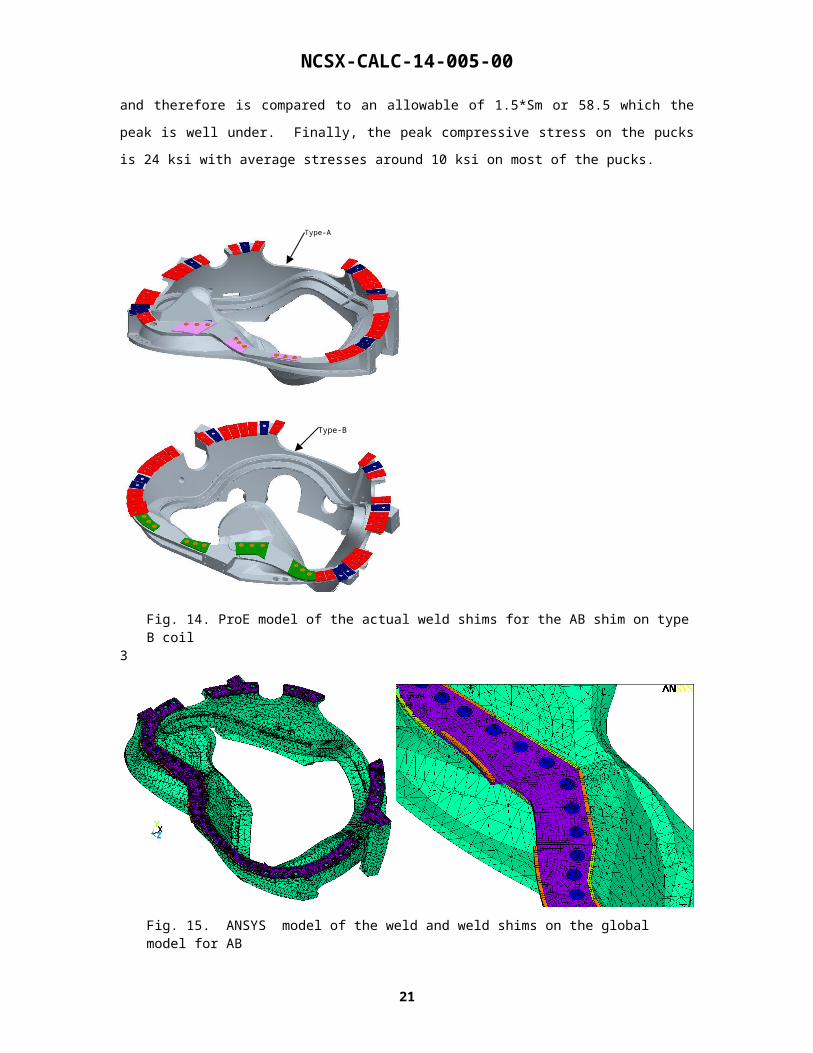
is compared to an allowable of 1.5*Sm or 58.5 which the peak is well under. Finally, the peak compressive
stress on the pucks is 24 ksi with average stresses around 10 ksi on most of the pucks.
Fig. 14. ProE model of the actual weld shims for the AB shim on type B coil
16
Type-A
Type-B

NCSX-CALC-14-005-00
3
Fig. 15. ANSYS model of the weld and weld shims on the global model for AB
Fig. 15. Global deflection of B casting with the AB weld.
17

NCSX-CALC-14-005-00
Fig. 16. Sliding on the shim/flange AB interface.
Fig. 17. Stress Intensity of the AB welded interface (global model).
18
Pucks are stuck on B flange
Pucks slide on A flange (0.227 mm)

NCSX-CALC-14-005-00
Fig. 18. Stress Intensity on the AB Shim and compressive stress on the pucks.
19

NCSX-CALC-14-005-00
4.3. BC Global Model with
The weld shim layout for the BC coil interface is shown in Fig. 19. The green shims represent those that are
to welded on each respective casting flange. The shims attached to the flanges in the figure are welded on
their backside to the flange surface. The weld itself is segmented by the shims and the gaps (.25") between
the shims. The purpose of alternating the shims in connecting across the flange is to prevent distortion of
the structure during welding. The weld types are fillets whose throat size is 0.3" and the length is
approximately 4" between breaks..
The finite element global model for the BC interface is shown in Fig 20. The weld is represented by a
rectangular hex mesh in all of the global model runs and it is not segmented. The shim area immediately
next to the weld and extending up and down to the first bolt has no contact elements present as the shim is
thinner than the gap between flanges. The shim covering the bolted areas is set to bonded contact. The
pucks are bonded to the B flange but are allowed to slide (keyopt 12 = 0) on the adjacent B flange. Thus,
they can carry compression (no tension) and allowed to slide. The pucks do not interface with the shims in
the analysis.
Fig 21 shows the global deflection of the C coil with the inclusion of the BC weld interface. These
deflections are approximately the same as those from the bonded inboard leg case studied earlier [2,3,5].
Fig 22 shows the sliding contact interface and status plots for the BC shim. Peak sliding of only 0.2 mm
occurs on one of the pucks. The contact status plot indicates that the pucks are stuck to the C surface as
designed. The stress intensity plot for the weld is shown in Fig 22 with a peak of 27 ksi. This peak occurs
on the corner of a weld and is treated as a geometric edge discontinuity which is anomalous. The average
stress through the weld is 16 ksi which is lower than the allowable and the AB stress but higher than the
AA weld case.
Fig 23 also shows the shim stresses and the puck compression stresses for the BC interface. The stress
intensity for the weld has a peak stress intensity of 36 ksi at the edge corner of one of the shims. The
average stress through the shim between holes is approximately 18 ksi near this peak stress and is well
under the allowable limit of 39 ksi (316 L). Finally, the peak compressive stress on the pucks is 37 ksi with
average stresses around 10 ksi on most of the pucks. The peak compressive stress once again occurs on the
corner edge of the pucks and would is not considered to cause any problems.
20

NCSX-CALC-14-005-00
Fig. 19. ProE model of the actual weld shims for the BC shim on type C coil.
Fig. 20. ANSYS model of the weld and weld shims on the global model for BC.
21
Type-B
Type-B
NCSX-CALC-14-005-00
Fig. 21. Global deflection on the C casting for the flange BC weld model.
Fig. 22. Sliding on the shim/flange BC interface.
22
Pucks are stuck on C flange Pucks slide on B flange (0.217
mm)

NCSX-CALC-14-005-00
Fig. 23: Stress Intensity for the a) weld, b) pucks, and c) shims for the BC weld model.
Fig. 24: Stress Intensity for the BC flange inner leg weld region and a close up view of the peak weld and shim stresses.
23
Welds Pucks Shims
Units = psi Units = psi Units = psi

NCSX-CALC-14-005-00
4.3. Tabular results for the global runs
Table 6 shoes the peak and average stresses for each model run for the weld, shims and pucks. As noted
above, the average shim stress for AB listed in the table is derived form one shim on the AB flange which
is narrow and has a relatively high shear load to react. A design change to reduce the size of the holes to
1.6" (section 5.2) reduces the stress to 24 ksi, which is more in line with the margin on allowable stress
(roughly a factor of 2) that the AA and BC shim stresses experience. All stresses shown are below the
allowables for peak edge discontinuities and average membrane stress.
Table 6: peak and average stress values for the global model runs of the AA, AB and BC weld areas.
FlangePeak weld stress Intensity (edges)
(ksi)
Average weld stress Intensity
(ksi)
Peak Shim Stress Intensity
(ksi)
Average Shim Stress
Intensity (ksi)
Peak Puck Compressive stress
(ksi)
AA 32 13 40 17 41
AB 32 17 39 34* 24
BC 27 16 36 18 37
*this number reduces to 24 as seen in section 5.2
5. Special analysis runs
5.1. AB weld Submodel
In the submodel run, the inner leg of the coil has been "cut-out" from the global model and re-meshed with
a much higher fidelity. Fig. 25 shows the AB weld cutout from the global model and its corresponding
mesh is shown in Fig. 26. Here, the weld is still represented as a sqaure profile and no fillets are included
in the image. The cut out on each flange section extends to the first bolt on the outboard side and the model
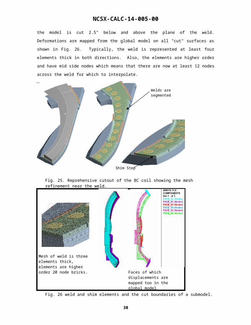
is cut 2.5" below and above the plane of the weld. Deformations are mapped from the global model on all
"cut" surfaces as shown in Fig. 26. Typically, the weld is represented at least four elements thick in both
directions. Also, the elements are higher order and have mid side nodes which means that there are now at
least 12 nodes across the weld for which to interpolate.
24

NCSX-CALC-14-005-00
Fig. 25. Reprehensive cutout of the BC coil showing the mesh refinement near the weld.
Fig. 26 weld and shim elements and the cut boundaries of a submodel.
Due to a ProE sweeping limitation, the welds end abruptly at the end of the pass. This is a
misrepresentation of the actual weld as it will likely smooth itself into the end of the flange and be
contoured thus removing the severe stress geometrical discontinuity that exists there. This is true of all of
the fillet welds. The primary purpose of this analysis is to produce directional stress plots which are used
to qualify the fatigue of this joint.
25
Welds are segmented
Shim Step
Mesh of weld is three elements thick, elements are higher order 20 node bricks.
Faces of which displacements are mapped too in the global model

NCSX-CALC-14-005-00
Fig. 27 shows the stress intensity plot of the submodel of the ab weld. The peak stress shown is 67 kis and
is found at the extreme corner of the filet weld (shown in the upper left of the breakouts in the figure). This
stress is very localized and is due to the geometric problem identified in the previous paragraph. The bulk
of the weld is at a rate considerably lower than 67 ksi, ranging from 14 to 18 ksi.
Fig. 28 illustrates the stress field on the shim and compares it to the global model results. One important
difference between the two models is that the submodel uses the correct shim thickness of 7/16" and thus
produces on average stresses that are 12.5% greater than its global counterpart. The peak stress occurs
along the edge of a hoile and is actually 28% greater than the global model. This is due to the increased
resolution of the mesh and the behavior of edge discontinuities. The closer and smaller the element gets to
the edge, the stress will increase. Still, at this resolution, the peak stress is still under the 1.5*Sm allowable
on a peaky edge.
Fig. 27: Stress Intensity of the shim and weld for the ab submodel.
26

NCSX-CALC-14-005-00
Fig. 28: Stress Intensity of the shim and weld compared to the max stress seen in the global model.
5.1. AB Middle shim redesign
Looking at Table 6 in section 4.4, the average stress on one shim on the AB study is approximately double
(34 vs 18 ksi) that of the other two flanges. If the hole size is reduced on that particular shim the average
stress between holes will be reduced since the shear area will increase. This is confirmed in Fig 29-31
where the average stress is decreased to 26 ksi from 34 ksi. However, the average stress is still higher than
the other two shims. Also, the puck stress does increase, as expected from 23 to 26 ksi as their size is
decreased. The other alternative to achieve the same margin on stress for all of the shims is to use a
different material on this one shim on AB. 316 LN, which has a higher yield and a higher ultimate strength
could be substituted.
Moving the puck holes to the left in the images shown was also tried but with mixed results. While the
average shim stress was reduced a bit further to 23 ksi, the peak puck stress increased considerably. Thus,
the current placement of the pucks should be held constant while the hole size should be reduced to 1.6"
27
Global Model results
Sub-model is actually modeled as 7/16” thick shim in places.

NCSX-CALC-14-005-00
Fig 29. stress comparison on ab shim for hole diametre variations.
Fig 30. Linerized stress intensity graphs for the two hole sizes on ab shim. .
28
2” holes 1.6” holes
2” holes 1.6” holes
Avg membrane stress = 34 ksiAvg membrane stress = 26 ksi

NCSX-CALC-14-005-00
Fig 31. Stress Intensity for the two puck size options for the ab joint.
29
2” holes 1.6” moved holes

NCSX-CALC-14-005-00
5.3. Including the bolts on the AB Interface
This section applies the same bolted procedure for the outboard bolted joint as has been done in the
previous outboard bolt analysis [3]. However, instead of modeling the inboard region with a finite
coefficient of friction, the welded joint is used. At one particular interface, pipe elements with appropriate
section properties are used to represent the characteristics of a bolted interface. Contact elements at this
interface are allowed sliding contact (no separation). Fig. 32 shows the pipe elements used to model the
bolt, connecting it to the hole via bar elements. The other bolted interfaces are modeled with Bonded
Contact.
The preload and bolt shear for the weld and bolt analysis is shown in Fig 33. All bolt loads see less than
1.5 kips. (Reminder: the reason for any loading on the bolts goes back to the contact stiffness of the
elements. This has been demonstrated in the past [3]. Higher contact stiffness yields better results but at
the cost of run time. Any loading below 2 Kips has been shown to be anomalous.). Thus, with the weld in
place the outboard bolts are all stuck and do not pick up any significant load.
Figure 34 shows the contact status and sliding of the bolts and inner pucks. It confirms that the bolts are
still stuck and that the pucks are allowed to slide. The peak sliding of the pucks is 0.23 mm and occurs in
the same area as the peak weld and shim stresses. Finally, Fig 35 demonstrates that the stress pattern for
the inner leg is essentially unchanged with the inclusion of the outboard bolts. The peak stresses for the
weld and the shim are within 1 ksi of the previous values and are occurring in the same locations. Thus,
Including the bolts does not effect the results of the welded inboard leg analysis and including the welds
does not effect the loading on the bolts (they all remain stuck).
Fig 32. Model showing both the welds and bolts in one model.
30
welds
bolts
NCSX-CALC-14-005-00
Fig 33. Bolt preload and bolt shear load for the weld and bolt analysis on the AB shim.
Fig 34.Contact status and sliding plots of the weld and bolt analysis..
31
The two center outer most bolts fall outside the +- 3 kip range centered on 72 kips. They are clearly far enough away from the inner leg to matter.
0
10
20
30
40
50
60
70
80
90
1 2 3 4 5 6 7 8 9 10 11 12 13 14 15 16 17 18 19 20 21 22 23 24 25 26
Bolt number
Pre
load
(ki
ps)
0
0.5
1
1.5
2
2.5
3
Bo
lt S
hea
r (k
ips)
preload (kips)
shear (pre+EM5) (kips)
Shim in the inboard area does not come into contact with the flanges, thus it is open.
NCSX-CALC-14-005-00
Fig 35. Stress Intensity for the weld and bolt analysis.
32
peak weld stress of 32 ksi (same location as before)
This area appears unaffected by outboard condition as expected
Stresses around bolts appear as they did in previous analysis

NCSX-CALC-14-005-00
6. Fatigue Study Courtesy I. Zatz PPPL
SUBJECT: Evaluation of Crack Growth in CF8M AB Shim Welds – Rev.1
REFERENCE: “77 K Fatigue Crack Growth rate of Modified CF8M Stainless Steel Castings” by Walsh,
et. al.
SUMMARY: Using the crack growth data of welded specimens from the referenced paper and the finite
element analyses results presented by Kevin Freudenberg for the AB shim welds (most recently dated
11/7/07), a calculation has been made estimating the maximum acceptable initial flaw size in ½-inch welds
to be 3.2 mm.
DISCUSSION: The referenced paper identifies that the average Paris constants in welded compact tension
crack growth specimens to be C = 3.1E-11 mm/cycle and n = 4.15. The tests were performed in
accordance to ASTM standard E647. The fracture toughness of the weld material at 77K was not indicated
in this paper or elsewhere in the literature.
When comparing the general trend of Stage II crack growth behavior between the base material and the
welded material, the indication is that the welded material appears to take longer to reach Stage II, but once
there, a crack will propagate more rapidly in the weld than in the base material. This conclusion is based
solely on comparing Paris constants, where the welds generally have a lower value of ‘C’ (which is a
measure of the initiation of Stage II crack growth), but a higher value of ‘n’ (Stage II crack propagation
rate).
Without a value of fracture toughness, a critical crack size in the welds cannot be ascertained; however, the
fracture toughness can be roughly estimated from the value of stress intensity observed at the end of Stage
II crack growth from the ASTM E647 test. This gives a first order sense of whether the critical crack sizes
in the welds are limiting. A fracture toughness value for the weld material at 77K of 65 MPa(m)1/2 was
obtained in this manner. Using a stress of 175 MPa (approximately 25 ksi) and appropriate geometric
correction factors, the critical crack size (which indicates failure) is calculated to be 10 to 11 mm.
The Paris constants allow for a crack growth calculation in welds when an initial flaw size is assumed.
Accordingly, a series of calculations were made that estimate the final flaw size in a weld when the cyclic
load, number of cycles and initial flaw size are specified. Note that the crack growth rate in such a
calculation is also dependent on the weld and crack geometry. The data represents a thru-edge crack in
tension (per the compact tension specimen used in the E647 test). No other data or fatigue curves for welds
were available for the potential variety of initial flaw geometries that may occur. Fortunately, the peak
33

NCSX-CALC-14-005-00
stresses observed in the Freudenberg calculations point to edge cracks in tension being the most likely
scenario, so that is consistent with the test data.
The following formula was used for the crack growth calculation:
N = (1 / [C*m*(S(Pi**0.5))**n] ) * [ (1 / ai**m) – (1 / af**m)]
Where:
N = Number of cycles – for 4 times life, 500,000 was used
C, n = Paris constants
m = (n/2)-1
ai = initial flaw size
af = final flaw size
S = Cyclic stress – chosen to be 175 MPa (this is a conservative value based on the
results of Kevin Freudenberg’s analyses)
This calculation shows the following results:
When ‘ai’ equals ‘af’ equals
1.0 mm 1.2 mm
2.0 mm 3.5 mm
3.0 mm 8.9 mm
3.2 mm 11.2 mm (critical crack size – failure)
This result indicates that a thru-edge flaw in the weld will propagate to an unacceptably large size in
500,000 cycles if the initial thru flaw is greater than 3.0 mm (approximately 1/8-inch). This is confirmed
by the estimated fracture toughness calculation based on a weld width of ½-inch (approximately 12 mm).
This back-calculates to an initial flaw size of 3.2 mm. Naturally, other initial defects in welds will produce
different results, but it should be noted that surface flaws have a tendency to propagate through, as well as
across, a material, until it usually evolves into a through flaw of the type on which this calculation is based.
Some additional life will naturally be achieved with a surface flaw as opposed to a through flaw, but how
much is unknown without additional data. So, to be as conservative as possible, it is recommended that the
thru-edge crack flaw propagation results, presented herein, be used. For welds smaller than ½-inch, the
initial acceptable flaw size will be smaller and would need to be re-calculated since the initial flaw does not
scale linearly with weld size.
The slides used to identify the directional stress components are shown in Appendix A.3
34

NCSX-CALC-14-005-00
7. Conclusion
All of the stresses presented in this analysis for the global weld interface studies are below the allowable
per the NCSX criteria.
The design has significant margin based on the following:
An analysis with the inboard region completely slipping (total weld shim failure and a lack of friction) shows that even though the first bolts may slip, the resulting shear load does not exceed the fatigue allowable of 9 kips/bolt. This assumes that each bolt has the design required bushing in place.
The baseline outboard bolt analysis with a coefficient of friction of 0.4 on the entire inner leg shows that the outer bolts do not slip (even the lead bolts). The welded joint will provide a stiffer connection than this modest friction coefficient.
The pucks in the weld model will impart some amount of shear through friction which reduce the shear on the shim/welds. The analysis currently only considers the condition where the pucks slide on a frictionless surface and carry no shear.
All of the structural and fatigue analysis have addressed the "worst case" magnetic configuration at 2T high beta. Most of the operation of NCSX will not be at this high field scenario.
The alumina friction coefficient seen in testing is actually 0.6. Analysis used 0.4 (or 2/3 of test value).
The welds are modeled as having sharp corners at their ends (stress discontinuities). In reality, the welds will be rounded and the stress risers will be reduced.
There are two areas shim/puck areas that analysis identified and asked for a slight redesign. The first is on
the AA interface near the mid-plane where two standard 2" pucks were replaced with an elongated
(amoeba) puck to react the compression loading. The second area of change was to reduce the size of the
pucks on one shim on the AB interface from 2" to 1.5". This allows for more margin on the average stress
through the shims when compared to the allowable.
Finally, based on the Zatz fatigue memo, the welds are rated for the life of the machine. That is, the results
indicate a flaw greater than 3.0 mm that will propagate to an unacceptably large size in 500,000 (5 X life).
Thus, as long as the initial detectable flaw is less than 3.0 mm, the welds are acceptable based on fatigue.
References
[1] ANSYS Inc, 275 Technology Drive, Canonsburg, PA 15317[2] K.D.Freudenberg "Non-Linear Modular Coil Analysis" NCSX-CALC-14-002-001, July 2007.[3] K.D.Freudenberg "Modular Coil Assembly Outboard Bolted Joint" NCSX-CALC-00-006, July
2007[4] W.D. CAIN, “MAGFOR: A Magnetics Code to Calculate Field and Forces in Twisted Helical
Coils of Constant Cross-Section”, 10th IEEE/NPSS Symposium on Fusion Engineering, 1983[5] H.M. Fan. "Nonlinear Analysis of Modular Coil and Shell Structure" NCSX-CALC-14-001-001,
February 2006[6] Voght et al. "Low Temperature Fatigue of 316L and 316LN Austenitic Stainless Steels",
Matallugical Transactions, March 14, 1990[7] NCSX Specification: NCSX Structural Design Criteria, NCSX-Crit-Cryo Nov 2004.
35

NCSX-CALC-14-005-00
A. Attachments
A.1 Bonded Interfaces
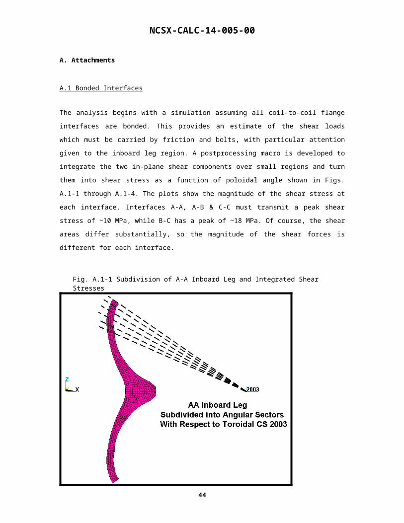
The analysis begins with a simulation assuming all coil-to-coil flange interfaces are bonded. This provides
an estimate of the shear loads which must be carried by friction and bolts, with particular attention given to
the inboard leg region. A postprocessing macro is developed to integrate the two in-plane shear
components over small regions and turn them into shear stress as a function of poloidal angle shown in
Figs. A.1-1 through A.1-4. The plots show the magnitude of the shear stress at each interface. Interfaces A-
A, A-B & C-C must transmit a peak shear stress of ~10 MPa, while B-C has a peak of ~18 MPa. Of course,
the shear areas differ substantially, so the magnitude of the shear forces is different for each interface.
Fig. A.1-1 Subdivision of A-A Inboard Leg and Integrated Shear Stresses
36

NCSX-CALC-14-005-00
A-A Inboard Leg Shear Stress
0
1
2
3
4
5
6
7
8
9
10
140 160 180 200 220
Angular Dist. from Outboard mid-plane, deg
Sh
ea
r S
tre
ss
, M
Pa
37

NCSX-CALC-14-005-00
Fig. A.1-2 Subdivision of A-B Inboard Leg (Similar to A-A) and Integrated Shear Stresses
A-B Inboard Leg Shear Stress
0
1
2
3
4
5
6
7
8
9
10
140 160 180 200 220
Angular Dist. from Outboard mid-plane, deg
Sh
ea
r S
tre
ss
, M
Pa
38

NCSX-CALC-14-005-00
Fig. A.1-3 Subdivision of B-C Inboard Leg (Similar to A-A) and Integrated Shear Stresses
B-C Inboard Leg Shear Stress
0
2
4
6
8
10
12
14
16
18
20
140 160 180 200 220
Angular Dist. from Outboard mid-plane, deg
Sh
ea
r S
tre
ss
, M
Pa
39

NCSX-CALC-14-005-00
Fig. A.1-4 Subdivision of C-C Inboard Leg (Similar to A-A) and Integrated Shear Stresses
C-C Inboard Leg Shear Stress
0
2
4
6
8
10
12
140 160 180 200 220
Angular Dist. from Outboard mid-plane, deg
Sh
ea
r S
tre
ss
, M
Pa
A.2. Letting the inboard leg slip.
40

NCSX-CALC-14-005-00
This section examines the impact on the outboard bolts if the entire inner leg slips on a frictionless surface.
This scenario is not very plausible but does provide a limit on what happens if for some reason the entire
inner leg connection on each joint fails. Looking at fig xx-xx, one can see that if the entire inner leg slips,
the first bolts on the AA and BC joint would in fact slip and exceed the frictional coating. However, the
resulting load that the bolt reacts is under the fatigue limit of 9 kips/bolt. The fatigue limit was derived in
the previous bolted joint analysis report [ref]. Therefore, even in the extreme case studied, the bolted joint
on the outside would survive but there would be motion on the inner leg of each connection on the order of
a 0.5 mm.
A-A Bolt Preload & EM-Driven Bolt Shear Load
0
25
50
75
100
1 2 3 4 5 6 7 8 9 10 11 12 13 14 15 16 17 18 19 20Bolt #
Ten
sio
n,
k-lb
0
1
2
3
4
5
6
7
8
Sh
ear
Lo
ad,
kip
Tension no pucks (Pre), kip
Shear with no inner leg friction or inner leg bolts(Pre+EM-Pre), kip
Fig A.2.1. Slippage and shear bolt loading on AA if the inner leg rides on a frictionless surface.
41

NCSX-CALC-14-005-00
A-B Bolt Preload & EM-Driven Bolt Shear Load
0
25
50
75
100
1 2 3 4 5 6 7 8 9 10 11 12 13 14 15 16 17 18 19 20 21 22 23 24 25 26
Bolt #
Te
ns
ion
, k
-lb
0
0.2
0.4
0.6
0.8
1
1.2
1.4
Sh
ea
r L
oa
d,
kip
Tension no pucks (Pre), kip
Shear with no inner leg friction or inner leg bolts (Pre+EM-Pre), kip
Fig A.2.2. Slippage and shear bolt loading on AB if the inner leg rides on a frictionless surface.
42

NCSX-CALC-14-005-00
B-C Bolt Preload & EM-Driven Bolt Shear Load
0
25
50
75
100
1 3 5 7 9 11 13 15 17 19 21 23 25 27 29 31 33
Bolt #
Ten
sio
n,
k-lb
0
1
2
3
4
5
6
7
Sh
ear
Lo
ad,
kip
Tension no pucks (Pre), kip
Shear with no inner leg friction or inner leg bolts (Pre+EM-Pre), kip
Fig A.2.3. Slippage and shear bolt loading on BC if the inner leg rides on a frictionless surface.
43

NCSX-CALC-14-005-00
A.3. Directional Stress slides used in fatigue study
Directional X weld stress
Max stress
Min stress
Directional Y weld stress
Max stress
Min stress
44
NCSX-CALC-14-005-00
Directional Z weld stress
Max stress
Min stress
More Z stress Images
Looking from top Looking from bottom
45