weight estimation using cad in the preliminary rotorcraft...
TRANSCRIPT

33rd European Rotorcraft Forum
Kazan, Russia, September 11-13th, 2007
1
Weight Estimation Using CAD In The Preliminary Rotorcraft Design
M. Emre Gündüz1, Adeel Khalid
2, Daniel P. Schrage
3
1Graduate Research Assistant, Daniel Guggenheim School of Aerospace Engineering,
Georgia Institute of Technology , Atlanta, GA. 30332, USA
Email: [email protected]
2Systems Engineer, Avidyne Corporation
55 Old Bedford Road, Lincoln, MA. 01742, USA
Email: [email protected]
3Professor, Daniel Guggenheim School of Aerospace Engineering, Georgia Institute of
Technology , Atlanta, GA. 30332, USA
Email: [email protected]
Key words: Concept, rotor, design, weight, computer, CAD
Abstract: Weight estimation of aircraft, including rotorcraft has always been a
critical part of design process. Since most aircraft are designed based on a baseline
similar to the concept at hand, current methods utilized for weight estimation rely on
either extrapolation using statistics and historical data, or analysis software based on
performance requirements. These approaches provide the designer with a rough
approximation at the concept generation stage, but they may not always be adequate
in the subsequent stages of design. They usually supply a total weight for each
subsystem of the aircraft, such as transmission group, rotor group, etc. They do not
assign a weight for each part in a subsystem assembly.
A method to be applied using Computer Aided Design (CAD) software during vehicle
engineering analysis for calculating weights of each component as well as the entire
aircraft is proposed. It helps acquiring detailed weight assessment earlier in the design
stage, and in turn, brings development costs down. This method depends on CAD
drawings of all components of the aircraft. The CAD program is linked with design
and analysis software. After any design change, the total weight can be recalculated
automatically, enabling detailed weight information in every design iteration. A
comprehensive weight optimization involving component size and shape
modifications can also be performed.
CAD software that permits assembly generation can also be utilized to obtain exact
location of center of gravity of the aircraft, for every conceivable passenger or
payload distribution during the mission.
For proof of concept, a Schweizer TH 330 helicopter and several other helicopter
rotors are modeled and calculated blade weights are compared with weights estimated
using Prouty’s equations [1]. It was found that even crude model of a helicopter rotor
with correct dimensions and airfoil shape may result in a better approximation to the
actual weight of the blades.
33rd European Rotorcraft Forum
Kazan, Russia, September 11-13th, 2007
2
1. INTRODUCTION
Estimating the helicopter weight has always been a challenge for weight engineers in
the conceptual and preliminary design stages. Several techniques have been suggested
in the past including the group weight estimation. Usually historical data from the
helicopters of same or similar class is used to approximate weights of individual
components. For example, the weights of avionics group can be obtained in the initial
design stage using rough estimates of avionics based on historical data. Prouty et al
[1] suggest lumping the weights of helicopter components into groups and using
historical data to formulate approximate empirical models. These techniques yield
results that are inaccurate and therefore do not provide satisfactory component
weights for the weights engineers. Lack of correct or accurate weight information
leads to incorrect estimation of cost and that results in several expensive design
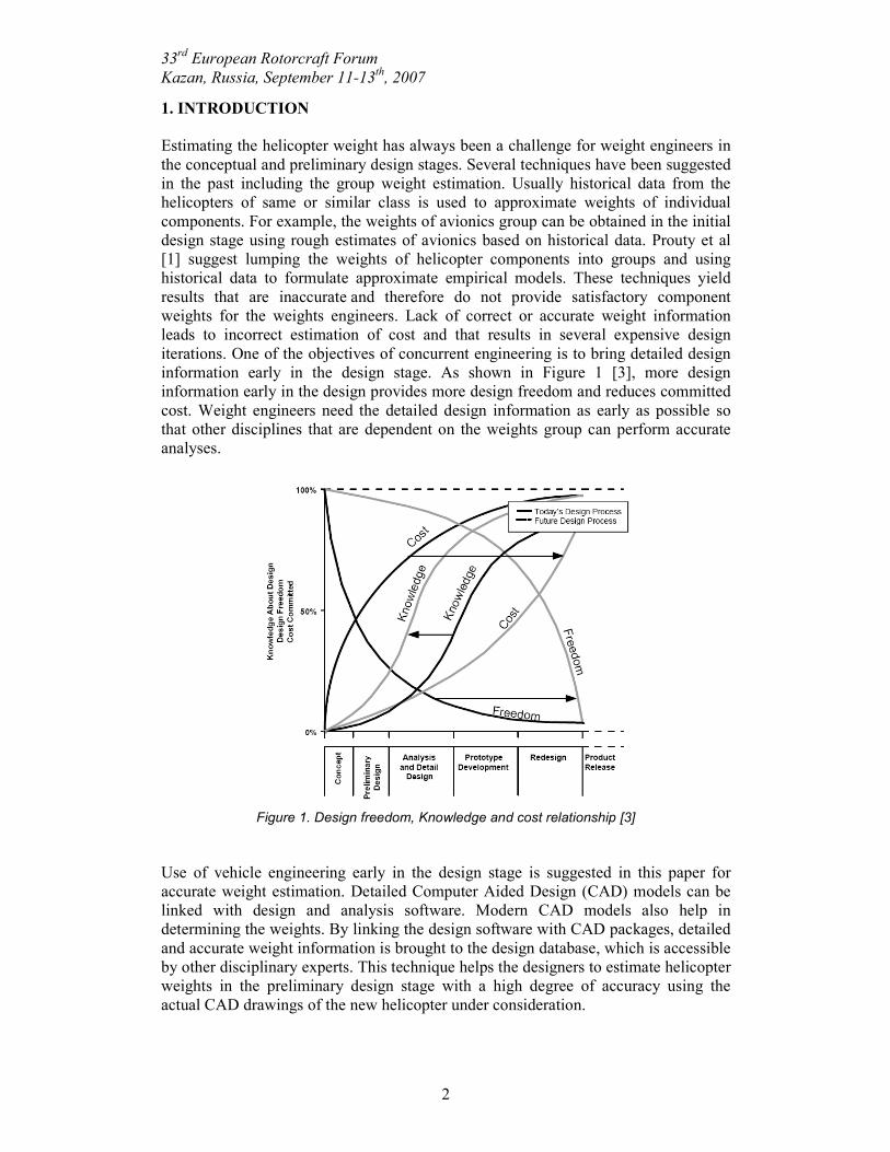
iterations. One of the objectives of concurrent engineering is to bring detailed design
information early in the design stage. As shown in Figure 1 [3], more design
information early in the design provides more design freedom and reduces committed
cost. Weight engineers need the detailed design information as early as possible so
that other disciplines that are dependent on the weights group can perform accurate
analyses.
Figure 1. Design freedom, Knowledge and cost relationship [3]
Use of vehicle engineering early in the design stage is suggested in this paper for
accurate weight estimation. Detailed Computer Aided Design (CAD) models can be
linked with design and analysis software. Modern CAD models also help in
determining the weights. By linking the design software with CAD packages, detailed
and accurate weight information is brought to the design database, which is accessible
by other disciplinary experts. This technique helps the designers to estimate helicopter
weights in the preliminary design stage with a high degree of accuracy using the
actual CAD drawings of the new helicopter under consideration.

33rd European Rotorcraft Forum
Kazan, Russia, September 11-13th, 2007
3
Once a link has been established between the CAD software and the design package,
updated weight information can be obtained as the design changes. Component
weights, and subsequently overall empty and gross weights do not have to be
recalculated every time the design changes. This approach guarantees automated
weight estimation. Additionally, once the weight calculation is automated, it can also
be optimized. This approach enables the designer to obtain detailed component
weights as opposed to group weights. The level of detail and precision of weights
depends on the level of accuracy and detail of the actual CAD model and component
material properties. This approach is evolutionary in nature. If the existing helicopter
weights information already exists, then this approach can be used to calculate and
update the weight information for a new design where all the changes in the design
are captured. This approach is also visual in nature. It is compatible with weight
reports used in industry and military, such as MIL-STD-1374. Using the CAD model,
the designer can also calculate the center of gravity and moments.
2. METHODOLOGY
Helicopter design consists of several disciplines that interact with each other. In an
optimization problem, design information flows between disciplines at every system
iteration as shown in Figure 2 [2]. One of the key disciplines in the preliminary
design process is the weight engineering. Traditionally, weights are estimated in the
initial design stage both by extensive experience and by good judgment about existing
and future engineering trends. Multiple linear regressions can be used to derive
equations for each aircraft component from weights data of previous aircraft. This
determines sensitivity with respect to every parameter that logically affects the weight
of the component [1]. The resulting equations are continually modified as more
modern helicopters are added to the database and as detail design of specific
components is accomplished. Prouty [1] lists a set of regression equations for
preliminary design weight estimates based on work done by Shinn et al [5, 6]. These
equations are used to determine the initial system weight estimates of fuselage,
landing gear, nacelle, engine installation, propulsion subsystems, fuel systems, drive
systems, cockpit control, instruments, hydraulics, electrical, avionics, furnishings and
equipments, air conditioning and anti icing, and manufacturing variations. This type
of analysis can be used for prediction of almost all the group weights that comprise
the helicopter empty weight, and is particularly applicable for the structural groups.
The weight prediction can be refined as the design progresses and applicable values
for increasing numbers of design parameters are determined. However in today’s
design environment where the design is iterative in nature and design variables
change from one iteration to the next, it can be very time consuming and tedious to
use the regression equations. Additionally the group weights obtained using
regression equations are estimates that may have significant error. These estimates are
often not suitable for new designs.
The new approach proposed in this paper is to calculate weights by using a vehicle
engineering or CAD package. CAD packages have improved significantly in the past
decade. In this particular study, CATIA by Dassault Sytemes is used to calculate
component weights. Detailed parameterized component CAD drawings are developed
using CATIA V5R16. These drawings are then linked with the Phoenix Integration
design software called ModelCenter. This link allows the designer to dynamically
change the part designs parametrically from ModelCenter by changing the variables

33rd European Rotorcraft Forum
Kazan, Russia, September 11-13th, 2007
4
as they get updated from one system level iteration to another. The updated empty
weight information is then used by other disciplines, which are dependent on weights
discipline for their calculations. This approach automates the weight estimation
process while providing an accurate weight estimate.
System
Optimization
Stability and
Control
Weight
Iteration
Aerodynamics
Figure 2. Interdisciplinary dependency and design iteration [2]
A wrapper is developed that helps establish a link between ModelCenter and CATIA.
Important design variables are specified in ModelCenter. By changing these variables,
the corresponding dimensions are updated in CATIA. This process is indicated in
Figure 3. The wrapper facilitates this process. Corresponding material properties are
specified in CATIA. These material properties are based on the best available
information at the early design stage. In this research, historical data is used for the
specification of material densities. In majority of new designs, the material details
may not be available at the early design stage or the designer may decide to keep the
material as a variable so the material information can be updated or new materials can
be added as the design progresses. The design variables may change significantly
from one iteration to another or over several iterations in a design process. For
example during the helicopter sizing process, the designer may decide to start with a
small rotor and then as the design matures, the rotor size may increase, as is the case
in most designs. This change in the rotor dimensions is reflected in the CAD
drawings. As the CATIA drawings get updated, the volumes and weights are
calculated automatically in CATIA and the updated information is sent back to
ModelCenter as shown in Figure 3. The component weights are then integrated in
ModelCenter to find group weights. Group weights are added to find the vehicle
empty weight. This updated weights information is then sent to various other
disciplines or system level optimizer in an optimization problem, as indicated in
Figure 2. The Component Weights (CW) are added in ModelCenter to get Group
Weights (GW). For example rotor blades, flexures and hub weights are added to get
the rotor group weight. Similarly group weights are added to get the vehicle Empty
Weight (EW). The addition process in ModelCenter is shown in Figure 4. This entire process of sending new variable information from ModelCenter to CATIA, update of
CAD drawings, new component weight calculations and addition of component and
group weights to get the vehicle empty weight is automated, which enables system

33rd European Rotorcraft Forum
Kazan, Russia, September 11-13th, 2007
5
iterations. With this methodology, the weights discipline’s works load is significantly
reduced.
Figure 3. Weight iteration between CAD (CATIA) and Design (ModelCenter) software
Figure 4. Component, Group and Empty weight calculation in ModelCenter
3. IMPLEMENTATION
The above mentioned methodology is implemented by means of modeling an entire
helicopter in CATIA, and comparing its weight calculations with the actual values.
Schweizer TH330 is modeled parametrically, as shown in Figure 5, and calculated rotor group weights are compared to provide rotor group weight of the rotorcraft by
the manufacturer.
Parametric design is crucial in this method because of the necessity to modify the various design
parameters quickly when switching between various concepts. For instance, with the CATIA
and ModelCenter models developed in this study, it is possible to modify the blade length, chord
lengths at the root and tip of the blade, and number of blades easily within ModelCenter without
Empty Wt.
Users
ModelCenter • Change design
variables
CATIA • Update drawings
• Calculate comp. Weights
New Design
Component Weights
CW – Component Weights
GW – Group Weights
EW – Empty Weight

33rd European Rotorcraft Forum
Kazan, Russia, September 11-13th, 2007
6
making any changes in CATIA. In addition it is relatively easy to switch between different airfoil
cross-sections, such as NACA0012, NACA23012, or SC1095 as long as the airfoil shape is
available in a table format of (x, y) coordinates in terms of chord length (c), as shown in Figure 6. The table values are fed into CATIA to obtain the exact blade cross-sections of unit chord length.
It is then possible to scale the cross-section to the desired chord length at the tip or at the root.
The number of blades can be changed from ModelCenter and the CATIA drawings get updated
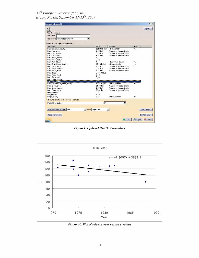
as shown in Figure 7. The wrapper file integrated in ModelCenter and the linkages between design variables
and actual physical dimensions in CATIA are shown in Figure 8. The variables that are passed to CATIA are the same parameters that change and
update drawings and are summarized in
Figure 9.
Figure 5. Isometric and parametric views of Schweizer TH 330 modeled in CATIA
X/c Y/c
1 0.00126
0.992704 0.002274
0.979641 0.004079
0.964244 0.006169
0.947231 0.008434
0.929323 0.010765
0.910956 0.013101
0.892372 0.01542
0.873723 0.0177
0.855041 0.019931
0.836311 0.022119
0.817558 0.024266
0.798819 0.026366
0.780088 0.028414
0.761336 0.030413
0.74256 0.03237
0.72378 0.034284
� �

33rd European Rotorcraft Forum
Kazan, Russia, September 11-13th, 2007
7
Figure 6. Airfoil geometry modeled in CATIA
Figure 7. Main rotor group designed in CATIA with inputs from ModelCenter
The model also allows changes in hinge offset. The possibility of making such
changes easily on the rotor enables the authors to obtain a rough model of most
conventional single-main-rotor helicopter rotors. For simplicity, potentially low-
weight components such as control linkages are removed from the design to keep it
more general, and the hinge-offset section is modeled as a single beam. Any forward
or backward sweep of the blade, or any built-in twist angles throughout the blade span
are also ignored, since they do not significantly affect weights.

33rd European Rotorcraft Forum
Kazan, Russia, September 11-13th, 2007
8
Figure 8. CATIA wrapper shown in ModelCenter design environment
Since there is very little knowledge about the details of the design in the conceptual
stage, it is acceptable to make use of historical weight data to make a relatively
reliable weight estimate. The main purpose of this research is to introduce high
fidelity tools early in the design process. It is, however, highly possible to have little
or no information about the design necessary to use those tools. For example, weight
of a blade depends highly on its inner structure and materials. Exact weights of the
blade can be calculated using CATIA if structural information and material
distributions within the blade are well defined. However it is very unlikely to have
knowledge of this level of detail in the beginning of design. Therefore as a first
approximation, blade, hinge offset and rotor hub in this research are modeled as
separate solid components, composed of one single material each. The density of each
material is predefined by the user, based on weights of other similar helicopter rotors
published by their manufacturers, i.e., historical data. A method for finding the
densities is explained below. Since the volume of any rotor blade can be matched
using CATIA, given necessary dimensions, the only data required is the density of the
material of the blade, in order to calculate the blade weight. Volumes are calculated
by CATIA, and weights are obtained from either published information or historical
data.
The densities to be entered into CATIA model are obtained by first calculating
‘weight/volume’ information of several helicopters. These approximated densities for
each helicopter are then inserted into the equation below:
100/5/1
ctipapp VVds ⋅⋅= (1)
33rd European Rotorcraft Forum
Kazan, Russia, September 11-13th, 2007
9
where dapp is approximated density, Vtip is the tip speed of blades, and Vc is cruise
speed of the rotorcraft. Vtip and Vc are given in design specifications, and dapp is
calculated as
designCADfromvolumeestimated
componenttheofweightd app = (2)
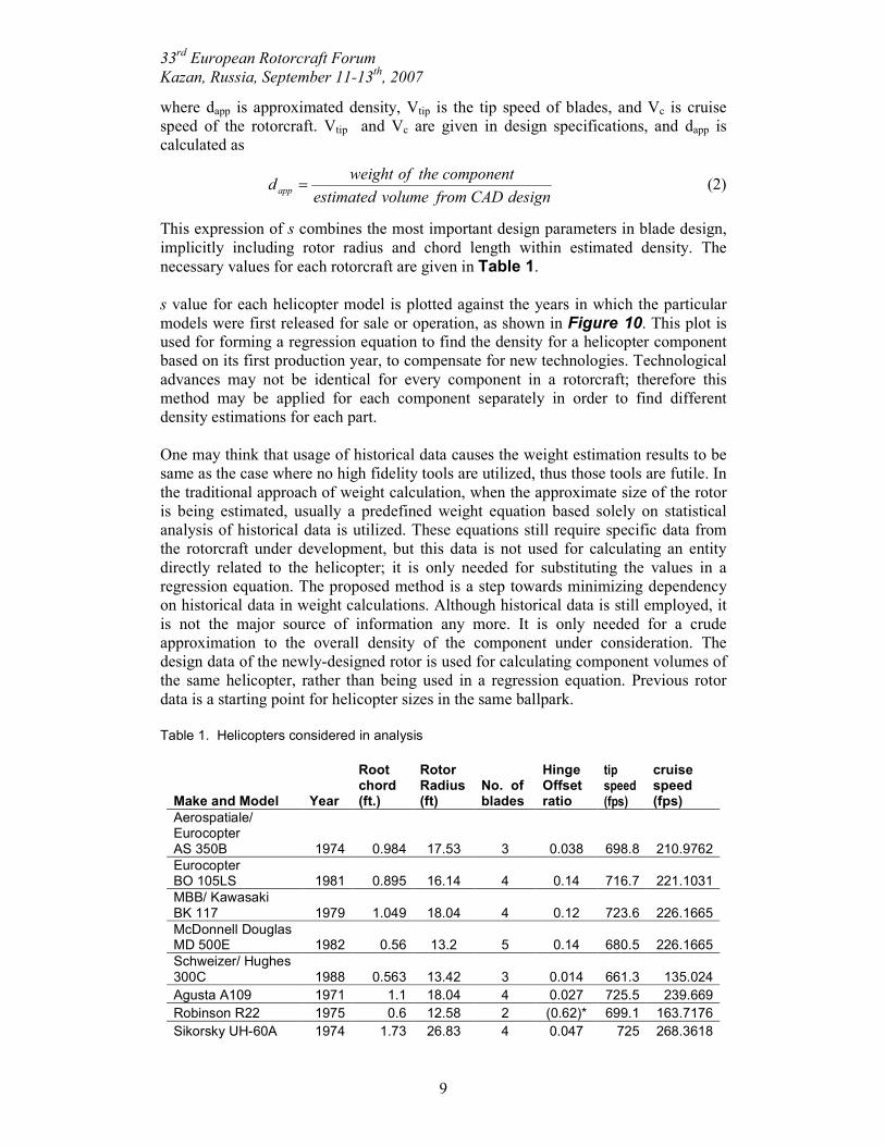
This expression of s combines the most important design parameters in blade design,
implicitly including rotor radius and chord length within estimated density. The
necessary values for each rotorcraft are given in Table 1.
s value for each helicopter model is plotted against the years in which the particular
models were first released for sale or operation, as shown in Figure 10. This plot is used for forming a regression equation to find the density for a helicopter component
based on its first production year, to compensate for new technologies. Technological
advances may not be identical for every component in a rotorcraft; therefore this
method may be applied for each component separately in order to find different
density estimations for each part.
One may think that usage of historical data causes the weight estimation results to be
same as the case where no high fidelity tools are utilized, thus those tools are futile. In
the traditional approach of weight calculation, when the approximate size of the rotor
is being estimated, usually a predefined weight equation based solely on statistical
analysis of historical data is utilized. These equations still require specific data from
the rotorcraft under development, but this data is not used for calculating an entity
directly related to the helicopter; it is only needed for substituting the values in a
regression equation. The proposed method is a step towards minimizing dependency
on historical data in weight calculations. Although historical data is still employed, it
is not the major source of information any more. It is only needed for a crude
approximation to the overall density of the component under consideration. The
design data of the newly-designed rotor is used for calculating component volumes of
the same helicopter, rather than being used in a regression equation. Previous rotor
data is a starting point for helicopter sizes in the same ballpark.
Table 1. Helicopters considered in analysis
Make and Model Year
Root chord (ft.)
Rotor Radius (ft)
No. of blades
Hinge Offset ratio
tip speed (fps)
cruise speed (fps)
Aerospatiale/ Eurocopter AS 350B 1974 0.984 17.53 3 0.038 698.8 210.9762
Eurocopter BO 105LS 1981 0.895 16.14 4 0.14 716.7 221.1031
MBB/ Kawasaki BK 117 1979 1.049 18.04 4 0.12 723.6 226.1665
McDonnell Douglas MD 500E 1982 0.56 13.2 5 0.14 680.5 226.1665
Schweizer/ Hughes 300C 1988 0.563 13.42 3 0.014 661.3 135.024
Agusta A109 1971 1.1 18.04 4 0.027 725.5 239.669
Robinson R22 1975 0.6 12.58 2 (0.62)* 699.1 163.7176
Sikorsky UH-60A 1974 1.73 26.83 4 0.047 725 268.3618

33rd European Rotorcraft Forum
Kazan, Russia, September 11-13th, 2007
10
Sikorsky CH-53E 1974 2.44 39.5 7 0.063 732 253.3537
Sikorsky S-76A 1977 1.29 22 4 0.038 675 244.7324
Bell JetRanger 206 1977 1.083 16.665 2 (0.098) 670.2 194.0981
* For rotorcraft with teetering rotors, the term “hinge offset ratio” represents the ratio of blade structure at the root enabling connections and controls to the blade structure with airfoil shape. Values for such rotorcraft are presented in parentheses.
A unique blade weight is estimated using CATIA model for the new design, and the
estimate is automatically updated for minute changes in blade geometry. As the
design progresses, interior structure of the blade and other components will be formed
eventually, thus crude density approximations will in turn be eliminated from the
design without affecting CAD models. Using the same models provide a smooth
transition between design, analysis and manufacturing stages of a product.
4. RESULTS & DISCUSSIONS
Effect of production year is incorporated by fitting a linear curve for the points in
Figure 10. The equation for that curve is used for finding approximate values of s.
Estimated densities are then found by solving the following modified equation of s
100/5/1
ctipest VVds ⋅⋅= (3)
to find dest. These estimated densities are then multiplied by CATIA blade volumes to
obtain estimated weights. Results of these calculations are given in Table 2. These weights may be compared to Poruty’s blade weights in terms of closeness to the
published blade weight of the rotorcraft. For example, published total blade weight of
Sikorsky CH-53E is 2120 lbs. Prouty’s equations yield 2264 lbs, and estimation using
the method described in this paper gives 2189 lbs. Although the CAD model crude
and generalized for multiple rotorcraft, it still manages to approximate the actual data
better than a statistics-based method.
This approach, when implemented on new designs or design modifications, can
greatly reduce the design time, cost and effort of the weight engineers and help the
system designers for overall design optimization.
In this research, ModelCenter is used to demonstrate the integration of different
software including CAD, Spreadsheets and Design software. Information flow
between these software is facilitated. It is shown that by linking the design software
with CAD packages, detailed and accurate weight information can be brought back at
the initial design stage. As the design matures and more information becomes
available, the weights information is update automatically. This information is also
passed to other disciplines dependent on weights. The entire process is automated,
thus significantly reducing the weight engineers’ work. For future work, more
parameterized components of helicopter, developed in the CAD package, can be
linked directly with ModelCenter. This will ensure that as the user changes the design
parameters or as the design information gets updated from other disciplines involved
in the design cycle, precise updated weights information is calculated automatically.
33rd European Rotorcraft Forum
Kazan, Russia, September 11-13th, 2007
11
Figure 9. Updated CATIA Parameters
s vs. year
y = -1.8057x + 3691.1
0
20
40
60
80
100
120
140
160
1970 1975 1980 1985 1990
Year
s
Figure 10. Plot of release year versus s values

33rd European Rotorcraft Forum
Kazan, Russia, September 11-13th, 2007
12
Table 2. CATIA results and estimated densities
Make and Model
CATIA blade volume (ft
3)
Weight / Volume
( appd )
Estimated density
( estd )
Estimated Blade Weights (lbs)
Prouty's Blade Weights (lbs)
Aerospatiale/ Eurocopter AS 350B 4.028 43.700 61.10669 243.2404 176.0252457
Eurocopter BO 105LS 3.678 71.778 26.206512 97.49366 176.9745477
MBB/ Kawasaki BK 117 5.769 41.787 25.39844 155.8142 241.0732115
McDonnell Douglas MD 500E 1.162 52.323 33.79633 45.32606 95.32845078
Schweizer/ Hughes 300C 1.039 66.021 214.0503 220.2993 68.59666497
Agusta A109 9.722 26.043 32.57084 348.3768 253.1979527
Robinson R22 0.805 66.287 157.819 160.6157 53.36181113
Sikorsky UH-60A 20.176 33.050 17.38828 333.7174 666.825784
Sikorsky CH-53E 101.666 20.852 20.2695 2189.057 2264.261225
Sikorsky S-76A 9.85 37.176 36.8463 248.1934 366.1893129
Bell JetRanger 206 2.571 74.120 70.1363 209.0921 134.9539122
5. REFERENCES
[1] Prouty, W. Raymond, “Helicopter Performance, Stability, and Control”,
Krieger Publishing Company, Malabar, Florida, 1995
[2] Khalid S. Adeel, “Development and Implementation of Rotorcraft Preliminary
Design Methodology using Multidisciplinary Design Optimization”, Ph.D.
Dissertation, Georgia Institute of Technology, December 2006
[3] Mavris, D.N., DeLaurentis, D.A., Bandte, O., Hale, M.A., A Stochastic
Approach to Multi-disciplinary Aircraft Analysis and Design, AIAA 36th
Aerospace Sciences Meeting and Exhibit, January 12-15, 1998
[4] http://www.flug-revue.rotor.com/Frtypen/FRSch330.htm
[5] Shinn, “Impact of Emerging Technology on the weight of Future Aircraft,”
AHS 40th forum, 1984
[6] Schwartzberg, Smith, Means, Law, & Chappell, “Single Rotor Helicopter
Design and Performance Estimation Programs,” USAAMRDL, SR 10, 77-1,
1977
[7] http://www.pagendarm.de/trapp/programming/java/profiles/NACA4.html
[8] http://www.ae.uiuc.edu/m-selig/ads/coord_database.html