week 10 - department of physicsphysics.ucsd.edu/students/courses/spring2009/physics2ba/10.pdf ·...
TRANSCRIPT

AC circuits
week 10

Applications
(leave for next week)


An inductor (inductance L) and a resistor (resistance R) are connected to a source of emf as shown. When switch S is closed, a current begins to flow and grows until it reaches a final value.
The final value of the current
1. is directly proportional to both R and L
2. is directly proportional to R and inversely proportional to L
3. is inversely proportional to R and directly proportional to L
4. is inversely proportional to both R and L
5. is independent of L

Rank in order, from largest to smallest, the time constants τa, τb, and τc of these three
circuits.
1. τa > τb > τc
2. τb > τa > τc
3. τb > τc > τa
4. τc > τa > τb
5. τc > τb > τa

Rank in order, from largest to smallest, the time constants τa, τb, and τc of these three
circuits.
1. τa > τb > τc
2. τb > τa > τc
3. τb > τc > τa
4. τc > τa > τb
5. τc > τb > τa

The switch in the figure has been open for a long time. It is closed at t = 0 s. (a) What is the current through the battery immediately after the switch isclosed?(b) What is the current through the battery after the switch has bee closed for a long time?(c) What is meant by a “long time” in (b)?
Ans: (a) 0.50 A (b) 1.0 A (c) a time much longer than 0.5 ms

An inductor (inductance L) and a
capacitor (capacitance C) are
connected as shown.
If the values of both L and C are
doubled, what happens to the time
required for the capacitor charge to oscillate through a complete cycle?
1. it becomes 4 times longer
2. it becomes twice as long
3. it is unchanged
4. it becomes 1/2 as long
5. it becomes 1/4 as long
Recall the angular frequency is ω = √(1/LC).The period T satisfies ωT = 2π, soT = 2π √(LC).
Therefore, doubling both L and C increasesT by the square root of 22

34-76. The switch in the figure has been in position 1 for a long time. It is changed to position 2 at t=0s. (a) What is the maximum current through the indictor?(b) What is the first time at which the current is maximum?
Ans: (a) 76 mA; (b) T=2.0 ms, tmax=T/4=0.50 ms

Important Concepts

Important Concepts

Key Skills

Key Skills

Applications
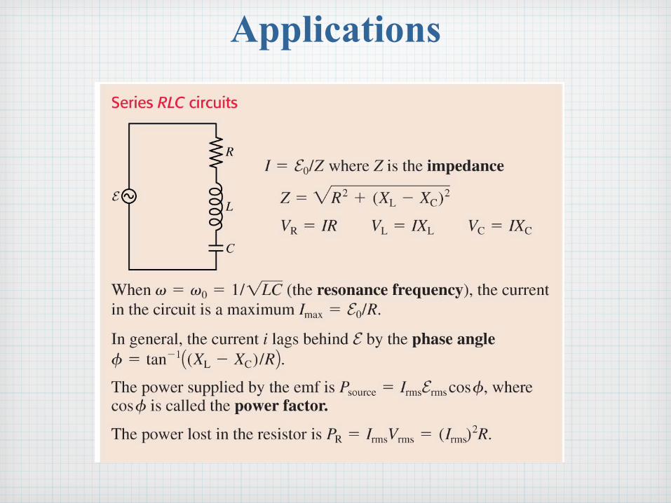
Applications

Resonance

A resistor is connected across an ac source as shown. Which graph correctly shows the instantaneous current through the resistor and the instantaneous voltage v = va-vb across the resistor?
(current “i” in purple, voltage “v” in blue)
1. 2. 3.

A resistor is connected across an ac source as shown. Which graph correctly shows the instantaneous current through the resistor and the instantaneous voltage v = va-vb across the resistor?
(current “i” in purple, voltage “v” in blue)
1. 2. 3.

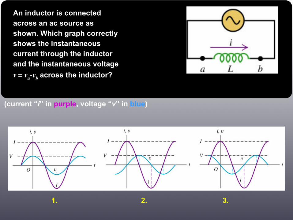
An inductor is connected across an ac source as shown. Which graph correctly shows the instantaneous current through the inductor and the instantaneous voltage
v = va-vb across the inductor?
(current “i” in purple, voltage “v” in blue)
1. 2. 3.

An inductor is connected across an ac source as shown. Which graph correctly shows the instantaneous current through the inductor and the instantaneous voltage
v = va-vb across the inductor?
(current “i” in purple, voltage “v” in blue)
1. 2. 3.


An capacitor is connected across an ac source as shown. Which graph correctly shows the instantaneous current through the capacitor and the instantaneous voltage
v = va-vb across the capacitor?
(current “i” in purple, voltage “v” in blue)
1. 2. 3.

An capacitor is connected across an ac source as shown. Which graph correctly shows the instantaneous current through the capacitor and the instantaneous voltage
v = va-vb across the capacitor?
(current “i” in purple, voltage “v” in blue)
1. 2. 3.


The resistor whose voltage and current phasors are shown here has resistance R
1. > 1 Ω.
2. < 1 Ω.
3. It’s not possible to tell.

The resistor whose voltage and current phasors are shown here has resistance R
1. > 1 Ω.
2. < 1 Ω.
3. It’s not possible to tell.

A capacitor is connected to a 15 kHz oscillator. The peak current is 65 mA when the rms voltage is 6.0 V. What is the value of the capacitance C?
Ans: 81 nF

In the figure, what are VR and VC (the peak potential differences across the resistor and the capacitor) if the emf frequency is 10 kHz?
Ans: VR = 6.0 V, VC = 8.0 V

A 500 μH inductor is connected across an AC generator that produces a peak voltage of 5.0 V. (a) For what frequency is the peak current 50 mA? (b) What is the instantaneous value of the emf at the instant when iL=IL (that is, when the instantaneous current equals the peak current)?
Ans: (a) 32 kHz, (b) 0

An L-R-C series circuit as shown is operating at its resonant frequency. At this frequency, how are the values of the capacitive reactance XC,
the inductive reactance XL,
and the resistance R related to each other?
1. XL = R; XC can have any value
2. XC = R; XL can have any value
3. XC = XL; R can have any value
4. XC = XL = R
5. none of the above

In an L-R-C series circuit as shown, the current has a very small amplitude if the emf oscillates at a very high frequency. Which circuit element causes this behavior?
1. the resistor R
2. the inductor L
3. the capacitor C
4. misleading question — the current actually has a very large amplitude if the frequency is very high

In an L-R-C series circuit as shown, there is a phase angle between the instantaneous current through the circuit and the instantaneous voltage vad
across the entire circuit. For what value of the phase angle is the greatest power delivered to the resistor?
1. zero
2. 90°
3. 180°
4. 270°
5. none of the above

What inductor in series with a 100 Ω resistor and a 2.5 μF capacitor will give a resonance frequency of 1.0 kHz?
Ans: 10 mH
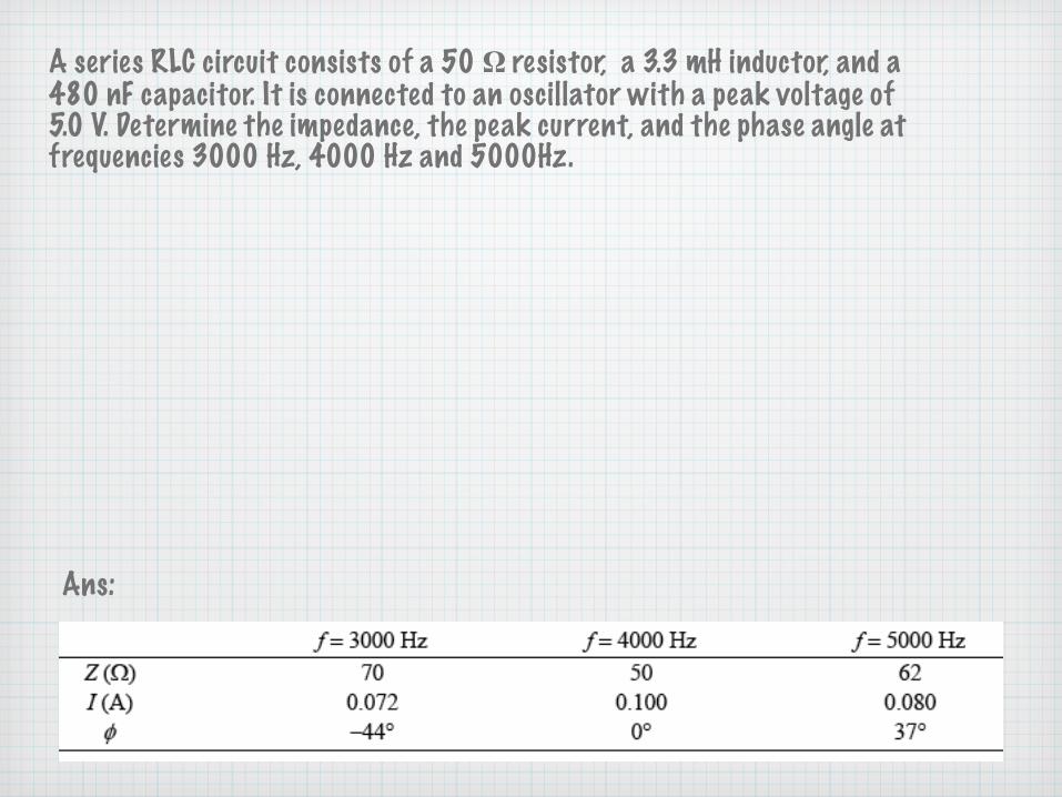
A series RLC circuit consists of a 50 Ω resistor, a 3.3 mH inductor, and a 480 nF capacitor. It is connected to an oscillator with a peak voltage of 5.0 V. Determine the impedance, the peak current, and the phase angle at frequencies 3000 Hz, 4000 Hz and 5000Hz.
Ans:

A series RLC circuit has VC = 5.0 V, VR = 7.0 V, and VL = 9.0 V. Is the frequency above, below or equal to the resonance frequency?
1. Above the resonance frequency
2. Below the resonance frequency
3. Equal to the resonance frequency

A series RLC circuit has VC = 5.0 V, VR = 7.0 V, and VL = 9.0 V. Is the frequency above, below or equal to the resonance frequency?
1. Above the resonance frequency
2. Below the resonance frequency
3. Equal to the resonance frequency

Here is a parallel RC circuit with an AC source. What are the peak currents IC, IR and I? What is the phase between the current i and the applied emf?
Follow-up: problems 36.70 and 36.71 in your textbook (all parallel orcombination of series/parallel LRC circuits)

The emf and the current in a series RLC circuit oscillate as shown. Which of the following would increase the rate at which energy is supplied to the circuit?
1. Decrease E0
2. Increase L
3. Increase C
4. Decrease L

The emf and the current in a series RLC circuit oscillate as shown. Which of the following would increase the rate at which energy is supplied to the circuit?
1. Decrease E0
2. Increase L
3. Increase C
4. Decrease L
Follow up: Is there another way to increase the rate at which energy is supplied?

A motor attached to a 120 V/60 Hz power line draws an 8.0 A current. Its average energy dissipation is 800 W.(a) What is the power factor?(b) What is the rms resistor voltage?(c) What is the motor’s resistance?(d) How much series capacitance needs to be added to increase the power factor to 1.0?
Ans: (a) 0.833 (b) 100 V (c) 12.5 Ω (d) 320 μF