r c^ - uc san diego | department of physicsphysics.ucsd.edu/neurophysics/manuals/lydall industrial...
TRANSCRIPT

:.; 'r c <
AFFINITY™ R-SERIES CHILLER
User Manual D5407
Lydall Industrial Thermal Solutions Inc. Post Office Box 1000
775 Route 16 Ossipee NH 03864 USA
Telephone: 603-539-3600 (Sales), 603-539-5005 (Service), Fax: 603-539-8484
Y:\MANUALS\D5408 REV; D (05nCV2CX)2) NK«T

Table of Contents Introduction
Equipment Precautions
Safety Precautions
Installation
Transporting
Placement
Electrical Requirements
Priming the Pump and Connecting the Coolant Loop
Operation
Using the Controller
Changing the Set-Value Temperature
Safety Alarms
Preventive Maintenance
25-Pin Interiock Description
Remote Switching Option
Trouble Shooting Guide
Warranty
Refrigeration Diagram
Fluid Flow Diagram
Electrical Schematic
Y:WANUALS\D4133 (06/31/2001)

Introduction
^Lydall i* Affinity
Congratulations on your purchase of an Affinity™ product.
I want to personally welcome you to the Lydall larger family. In October of 2001, Lydall purchased Affinity Industries, in an effort to expand capability as a Total Thermal Solutions Provider. Affinity's chillers and heat exchangers complement Lydall's existing wide array of Passive Thermal Solutions, augmenting Lydall's engineered thermal solutions for use in appliance, cryogenic, building products, and automotive markets. Our group is market driven as a formidable thermal solution manufacturer.
Lydall, Inc. is a New York Stock Exchange listed company (NYSE: LDL) headquartered in Manchester, CT. Our company, with ten operations in the United States, France, one in Gennany, and Sales/Service Offices in Japan and Singapore, is recognized for working with customers to satisfy their unique thermal solution needs, and for delivering high quality, innovative products, and exceptional service.
Affinity™ products are high-precision specialty temperature-controlled equipment. The following product manual is designed to help you realize the full value of your purchase.
We highly recommended that you read this manual in its entirety. The manual will assist your company with the installation, operation, and routine maintenance of your Affinity™ product. Please keep this manual readily accessible to operation and service personnel to ensure you get the most out of our product.
If you have any questions about this model, or have other thernial solution needs, do not hesitate to call our Sales department (603-539-3600) or the 24/7 Service department (603-539-5005).
Thank you for your confidence in our ability to meet and/or exceed your needs and expectations.
Sincerely,
John Tattersall Group Vice President Lydall Industrial Thermal Solutions, Inc.
Y:\MANUALSU)3774 (01/11/2002)

Equipment Precautions
Failure to adhere to these precautions will void the warranty and may damage the chiller.
1. This chiller has been shipped without coolant. Do not run it without connecting the coolant lines and keeping them filled with the appropriate coolant. Never run the pump without prime because it will quickly be damagecj without liquid.
2. The chiller is designed for indoor use only. Do not operate the chiller in ambient temperatures below 7 C (45 F) or above 30 C (85 F). Operation above 30 C will derate the chiller's cooling capacity. If the chiller has been exposed to temperatures below 7 C, allow twenty-four hours at ambient temperature aljove 7 C to warm the oil in the compressor as well as the refrigerant before starting.
3. Maximum storage temperature for the unit is 52 C(125 F).
4. Never use coolants which are incompatible with the components in the chiller's coolant loop. Some coolants may not damage the coolant loop components yet may significantly derate the chiller's cooling capacity. Never use automotive antifreeze or other antifreeze containing silicates because they will cause the pump seals to fail. Check with the factory if there are questions about the coolant.
5. Routinely inspect the pump inlet strainer located in the reservoir for buildup of debris. Turn the chiller off, then remove and clean the strainer as required to permit free flow of coolant. Prevent foreign debris from entering coolant lines while the strainer is removed. Hint: A plastic sandwich bag may be used to wrap the strainer to contain most of the debris. Failure to keep the strainer clean will reduce coolant flow and may damage the pump.
6. Do not operate the chiller at coolant temperatures above or below the values it was specified to deliver.
7. Do not operate the chiller with cooling loads that exceed its factory rated cooling capacity.
8. The cabinet of the chiller is designed to vent air. Maintain free space, equal to the height of the chiller, for flow of air on the condenser side of the chiller (opposite to where the coolant lines connect). The two sides or the top must have an equal amount of free space. When air flow becomes impeded, cooling capacity decreases and electrical efficiency drops as motor load increases.
9. Regulariy check the condenser for dirt, dust, etc.. To clean, disconnect the electrical power cord and remove the bonnet. Check and clean the condenser as required. Condenser fins bend easily. Use care when cleaning.
10. Do not operate damaged or leaking equipment.

Equipment Precautions
11. The chiller must not be transported unless suitably protected. Original factory packaging in good condition or equivalent is required. Request air-ride trucks if transporting over land.
12. The chiller should be thoroughly drained and the coolant lines blown dry with low pressure compressed air before shipping or storing.
13. Modifying the chiller without express written consent from Lydall will void the warranty.
Y:\MANUALS\D3795 (05/13«002)

Safety Precautions
1. Heed all warning labels. Do not remove.
2. Do not operate the chiller with the bonnet removed. The bonnet protects personnel from rotating parts and hot surfaces and also protects the chiller's components.
3. Connect the chiller, in compliance with the NEC (National Electric Code) for American usage and lEC 127 for European usage as well as local codes, to a fused disconnect box. Maximum fuses must not exceed the maximum rating found on the serial tag on the electrical box. The voltage, phase, and frequency of the power source must also match the requirements specified on the serial tag. To reduce the risk of electric shock:
Do not remove cover of the remote control box (if included). Refer servicing to properly qualified and licensed personnel.
Disconnect electrical power before opening the electrical box, except for the checking of the phase reverse relay or phase monitor if included with this unit (phase reverse relays or phase monitors will never be included in single phase units). Power must be applied in order for the phase reverse relay or phase monitor to indicate phase sequence.
Do not operate equipment with damaged electric power cords.
Turn off the chiller and disconnect electric power before servicing or moving.
4. Coolant lines, filters, and other components which connect to the chiller must be capable of withstanding the maximum pressure that the pump in the chiller can deliver at the maximum expected temperature.
5. The coolant loop has not been designed for potable water applications. Do not use the chiller for potable water. Never hook the water lines of a water-cooled unit to a potable water source without providing back flow protection. Do not immerse a hose connected to a potable water source in the reservoir. A loss of pressure in the water source could lead to a back flow of the fluid in the unit, resulting in a possible contamination of the potable water source.
6. Vapors of some alcohol based antifreezes as well as other coolants may cause explosion if exposed to flame or spark.
7. Certain antifreezes may be poisonous if ingested.
Y:\M/y^UALS\D3799 (02/01/2001)

Installation
Transporting
An Affinity™ chiller rolls easily on four swivel casters. The brakes must be off on the two locking casters when moving the unit. Roll the chiller gently to its operating location. The cushioned casters will help to dampen shock; Lock the casters when the unit is in place. If a forklift will be used to carry the chiller, proceed slowly and carefully to avoid jarring the unit, being careful to prevent damage to the casters.
If the chiller will be shipped, protect it from shock and vibration or the warranty will be void. The chiller must not be transported unless suitably protected. Original factory packaging in good condition or equivalent is required. Request air-ride trucks when transporting over land.
Thoroughly drain the coolant lines and blow them dry with low pressure compressed air before shipping or storing. Lydall will not accept any unit containing measurable amounts of fluid. Fluid left in the unit during shipping may damage components within the unit. Such damage is not covered by warranty.
Placement
Select a level location, near the application, free from dripping or spraying moisture and excessive dust. Keeping coolant lines short allows the pump to provide maximum pressure and flow to the application. If the chiller will be placed more than 25 feet from the application, call Lydall service to discuss placement and how it might affect performance.
Units with non-pressurized reservoirs should never be installed more than 25 feet below the process or overflow may occur. Distances may vary slightly due to elevations above sea level. Call 603-539-5005 for more information.
Electrical Requirements
Connect the chiller, in compliance with the NEC (National Electric Code) for American usage and I EC 127 for European usage as well as local codes, to a fused disconnect box. Maximum fuse sizes in the disconnect box must not exceed the maximum ratings specified on the serial tag of the chiller (found on the electrical box). The voltage, phase, and frequency of the power source must also match the requirements specified on the serial tag.
Note: Affinity™ models that can operate at either 208- 230 Volts, 60 Hertz, or 200-240 Volts, 50 Hertz have been set at the factory for 208 Volt operation. If the operating voltage will be greater than 220 Volts, a qualified electrician should remove the red wire from the contactor and replace it with the orange wire taken from the dummy fuse block. Attach the red wire to the dummy fuse block (see diagram below). All voltages may not be compatible with this unit. See the unit's serial tag for the proper voltage range.

Installation
TYPICAL CONFIGURATION ELECTRICAL SCHEMATIC
N INTERCHANGE
Z RED AND CRN
ID OIANGC VOITACX
REMOVED FROM
POWER lERMINAC
( -\ I I I I CONNECT FOR
SYSTEM VOLTAGE , , I I
CT l 75VA
NOTE: IN SOME C : A S E S PRESSURE SCREW TERMINAL B L C X : K S
ARE USED IN P U C E OF FASTON TERMINATIONS
aa 0 D
Warning: To reduce the risk of electric shock, do NOT remove cover from the electrical box. It contains exposed high voltage wires. Refer servicing to qualified personnel. Disconnect power to the chiller before performing any service.
Priming the Pump and Connecting the Coolant Loop
DO NOT RUN THE PUMP DRY. If the pump does not establish prime, the pump shaft seal may overheat and be damaged in less than a minute. Use the following instructions when filling and assembling the coolant lines to prevent damage to the pump shaft seal.
1. Close the reservoir drain.
2. Fully open the flow control valve.
3. Have extra coolant to add as the pump primes and the coolant loop fills.
4. Fill the reservoir with coolant. Do not fill above the height of the coolant loop connection fittings or fluid will leak out. Do not place a hose connected to a potable water source in the reservoir. A drop in pressure in the potable water supply could cause back flow, resulting in the possible contamination of the water supply.

Installation
5. . Connect the coolant lines from the application to the FPT (female pipe thread) fittings near the top of the chiller as follows. Do not over tighten the insert and do not use a sealant that will lock the male threads to the female threads. a. Connect the coolant line coming back from the application to the RETURN
fitting. b. Connect the coolant line going to the application to the SUPPLY fitting.
\ 1 / ./N
RETURN SUPPLY
6. When the previous steps are complete, turn the chiller on by placing the ON/OFF/SET switch in the ON position. Immediately check for flow. If within five seconds no turbulence is visible in the reservoir or the supply pressure gauge shows no pressure reading, shut the chiller off by placing the ON/OFF/SET switch in the OFF position. If flow is established, continue filling the reservoir until the low level alarm shuts off. Do not allow the reservoir to overflow.
7. If the pump does not establish prime, disconnect the SUPPLY coolant line to vent any trapped air, reconnect the line, and repeat step 6.
8. If the pump still does not prime, use the following steps: a. Disconnect both coolant lines (have a container handy to catch any overflow
from the RETURN fitting). b. Force coolant into the SUPPLY fitting. The fluid will force the air out of the lines
in the chiller and out of the pump head, causing it to escape into the reservoir. If tap water will be the source of coolant, simply connect the tap water line to the SUPPLY fitting and turn on the tap. If a source of coolant other than tap water will be used, elevate the coolant a few feet above the chiller, connect to the SUPPLY fitting, and let gravity force the air out into the reservoir. Remember to have a container handy to catch any overflow from the RETURN fitting.
c. Reconnect the coolant lines and repeat step 6. Stop filling when the reservoir is full to within an inch or two of the top. Do not allow the reservoir to overflow.
A stainless steel mesh strainer attaches to the pump suction port near the bottom of the reservoir. It can easily be removed for cleaning. First turn the pump off, then pull off the strainer, rinse it clean, and push it back on. To protect the pump, routinely inspect the strainer to be sure it is clean and properiy attached. Hint: If the strainer is coated with debris, wrap it with a plastic sandwich bag before pulling it off to prevent most of the debris from escaping into the reservoir.
Y:\MANUALS\D3780 (05/18/2002)

Operation
Using the Controller
This Affinity™ chiller comes standard with a FUJ11/16 DIN temperature controller. This controller is a programmable microprocessor, which offers many more features than are necessary to master at this point. If more than the basic instructions provided in this manual will be needed, consult the FUJI Instruction Manual.
Afnntty 0© H® L®
PV ©
SV ®
8. 8. 8. 8.
V A A
PV/SV SEL
A
DATA ENT
EHZA.
Place the ON/OFF/SET switch on the control box (if included with this chiller) or the chiller's control panel near the Fuji controller in the SET position. SET activates the control display but does not turn on the refrigeration and pump systems of the chiller. Four dots will appear on the display, then in 3-4 seconds the temperature of the coolant will appear plus an indicator light next to PV. Indicator lights next to C, H, or L may also appear. The function of these lights will be discussed later in the section on Safety Alarms.
Press PV/SV until the indicator light appears next to SV to display the Set-Value temperature. The Set-Value temperature can be changed to any temperature within the range programmed for this Affinity™ model. Note: Pressing PV/SV allows toggling the indicator light between PV, the actual process coolant temperature, and SV, the Set-Value temperature.
Changing the Set-Value Temperature
Change the Set-Value temperature by pressing PV/SV until the indicator light appears next to SV. Then directly under the digit in the display to be changed, press ( ) and the digit will start blinking. To increase the digit value, press ( ) under the blinking digit as many times as necessary; To decrease the digit value, press ( ) at the left side of the controller. Press ( ) under the next digit value to be changed and repeat the process. When all the digits are set to the desired value and with one digit still blinking, press the red (ENT) key at the far right of the controller to enter the new Set-Value temperature.
Operation
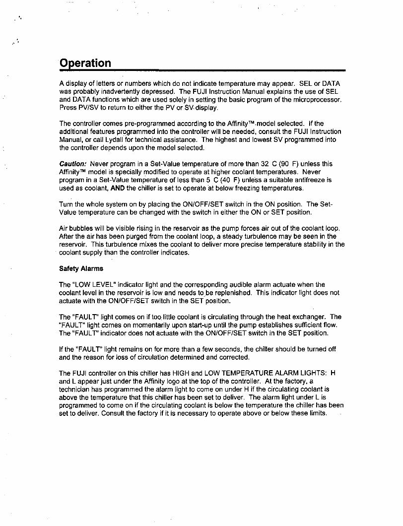
A display of letters or numbers which do not indicate temperature may appear. SEL or DATA was probably inadvertently depressed. The FUJI Instruction Manual explains the use of SEL and DATA functions whicli are used solely in setting the basic program of the microprocessor. Press PV/SV to return to either the PV or SV display.
The controller comes pre-programmed according to the Affinity™ model selected. If the additional features programmed into the controller will be needed, consult the FUJI Instruction Manual, or call Lydall for technical assistance. The highest and lowest SV programmed into the controller depends upon the model selected.
Caution: Never program in a Set-Value temperature of more than 32 C (90 F) unless this Affinity™ model is specially modified to operate at higher coolant temperatures. Never program in a Set-Value temperature of less than 5 C (40 F) unless a suitable antifreeze is used as coolant, AND the chiller is set to operate at below freezing temperatures.
Turn the whole system on by placing the ON/OFF/SET switch in the ON position. The Set-Value temperature can be changed with the switch in either the ON or SET position.
Air bubbles will be visible rising in the reservoir as the pump forces air out of the coolant loop. After the air has been purged from the coolant loop, a steady turbulence may be seen in the reservoir. This turbulence mixes the coolant to deliver more precise temperature stability in the coolant supply than the controller indicates.
Safety Alarms
The "LOW LEVEL" indicator light and the corresponding audible alarm actuate when the coolant level in the reservoir is low and needs to be replenished. This indicator light does not actuate with the ON/OFF/SET switch in the SET position.
The "FAULT' light comes on if too little coolant is circulating through the heat exchanger. The "FAULT" light comes on momentarily upon start-up until the pump establishes sufficient flow. The "FAULT" indicator does not actuate with the ON/OFF/SET switch in the SET position.
If the "FAULT' light remains on for more than a few seconds, the chiller should be turned off and the reason for loss of circulation determined and corrected.
The FUJI controller on this chiller has HIGH and LOW TEMPERATURE ALARM LIGHTS: H and L appear just under the Affinity logo at the top of the controller. At the factory, a technician has programmed the alarm light to come on under H if the circulating coolant is above the temperature that this chiller has been set to deliver. The alarm light under L is programmed to come on if the circulating coolant is below the temperature the chiller has been set to deliver. Consult the factory if it is necessary to operate above or below these limits.

Operation
The light on the FUJI controller next to C, when lit, indicates that the refrigerant solenoid valve is open to allow refrigerant to flow to the heat exchanger. If the light is on most of the time, most of the capacity of the chiller is in use. If the light is on infrequently, much less than the full capacity of the chiller is being used.
Preventive Maintenance
A stainless steel mesh strainer attaches to the pump suction port near the bottom of the reservoir. It can easily be removed for cleaning. First turn the pump off, then pull off the strainer, rinse it clean, and push it back on. To protect the pump, routinely inspect the strainer to be sure it is clean and properiy attached. Hint: If the strainer is coated with debris, wrap it with a plastic sandwich bag before pulling it off to prevent most of the debris from escaping into the reservoir. The frequency of checking and cleaning this strainer will depend on the cleanliness of the process and the fluid.
Regulariy check the condenser, located in front of the fan, for dirt, dust, etc.. To clean, disconnect the electrical power cord and remove the bonnet. Check and clean the condenser as required using a vacuum or low pressure air. Condenser fins bend easily. Use care when cleaning.
Y:\MANUALS\D5251 (05/17/2002)

25 Pin Flow, Temperature, and Level Interlock
The 25 pin flow, temperature, and level interiock consists of a 25 pin D-subminiature connector installed on the electrical box and the wires and alarm relays necessary to provide the desired functions. This option is not technically an interiock, as it does not stop or prevent operation of the chiller, but rather provides a remote alarm indication. The flow and level conditions each control a normally open (NO) and a normally closed (NC) contact on the 25 pin connector. The temperature condition is programmable to either NC (the standard) or NO, but not both.
A Remote Run option (Local/Remote or Remote On/OfO is also wired to the 25 pin (x>nnector.
The 25 pin connector provides continuity/discontinuity only. No voltage is applied by the chiller to pins on the connector except that pin 5 is hot (24 VAC) if a remote run option is specified. All conductors and terminals are rated 30 volts AC or DC, 1 amp maximum. The pin assignments are standardized as follows:
Flow alarm (Fault) Pins 15 and16 closed, pins 14 and15 open with the chiller operating nomnally Pins 15 and16 open, pins 14 and15 closed in the alarm state
Temperature alarm: Pins 9 andIO closed when temperature is within the setpoint range, open in the alarm state
Level alarm: Pins 11 and12 open, pins 12 and13 closed with the chiller operating normally Pins 11 and12 closed, pins 12 and13 open in the alarm state
Remote Run Option: Connect remote switch to pins 5 and 6.
Note that the flow contacts are in the alarm state when the chiller is off.
Y:\MANUALS\D5409 (05/17/2002)

Remote Switching Option
Local/Remote
The Local/Remote option consists of a two position switch mounted on the unit, wired directly to the control power circuitry in the electrical box and a multi-pin connector of the customer's choice. When the Local/Remote switch is in the Local position, the local ON/OFF/SET switch on the unit will function normally. When the switch is in the Remote position, the unit will operate only if the customer's remote switch is in the ON (or RUN) position.
Y:\M/WUALS\D3823 (1/12/1999)
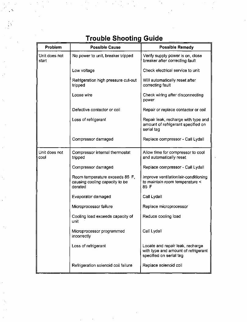
Problem
Unit does not start
Unit does not cool
Trouble Shooting Possible Cause
No power to unit, breaker tripped
Low voltage
Refrigeration high pressure cut-out tripped
Loose wire
Defective contactor or coil
Loss of refrigerant
Compressor damaged
Compressor internal thermostat tripped
Compressor damaged
Room temperature exceeds 85 F, causing cooling capacity to be derated
Evaporator damaged
Microprocessor failure
Cooling load exceeds capacity of unit
Microprocessor programmed incorrectly
Loss of refrigerant
Refrigeration solenoid coil failure
Guide Possible Remedy
Verify supply power is on, close breaker after correcting fault
Check electrical service to unit
Will automatically reset after correcting fault
Check wiring after disconnecting power
Repair or replace contactor or coil
Repair leak, recharge with type and amount of refrigerant specified on serial tag
Replace compressor - Call Lydall
Allow time for compressor to cool and automatically reset
Replace compressor - Call Lydall
Improve ventilation/air-conditioning to maintain room temperature < 85 F
Call Lydall
Replace microprocessor
Reduce cooling load
Call Lydall
Locate and repair leak, recharge with type and amount of refrigerant specified on serial tag
Replace solenoid coil

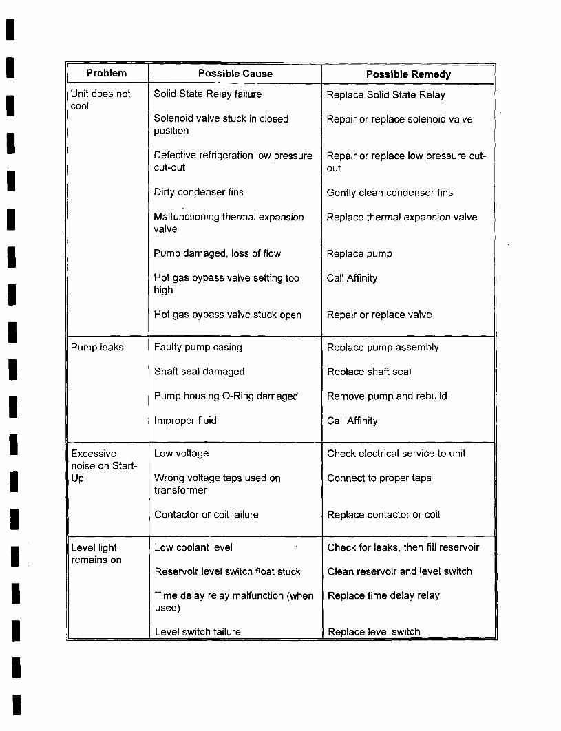
1 Problem
Unit does not cool
Pump leaks 1
Excessive noise on Startup
Level light remains on
Possible Cause
Solid State Relay failure
Solenoid valve stuck in closed position
Defective refrigeration low pressure cut-out
Dirty condenser fins
Malfunctioning thermal expansion valve
Pump damaged, loss of flow
Hot gas bypass valve setting too high
Hot gas bypass valve stuck open
Faulty pump casing
Shaft seal damaged
Pump housing O-Ring damaged
Improper fluid
Low voltage
Wrong voltage taps used on transformer
Contactor or coil failure
Low coolant level
Reservoir level switch float stuck
Time delay relay malfunction (when used)
Level switch failure
Possible Remedy
Replace Solid State Relay
Repair or replace solenoid valve
Repair or replace low pressure cutout
Gently clean condenser fins
Replace thermal expansion valve
Replace pump
Call Lydall
Repair or replace valve
Replace pump assembly
Replace shaft seal
Remove pump and rebuild
Call Lydall
Check electrical service to unit
Connect to proper taps
Replace contactor or coil
Check for leaks, then fill reservoir
Clean reservoir and level switch
Replace time delay relay
Replace level switch

Problem
Level light does not wori<
Pump motor overheats
Noisy compressor
Fault light remains on
Low coolant flow
Possible Cause
Time delay relay (where used)
Lamp burned out
Level switch failure
improper voltage supplied to unit
Flooding of refrigerant into crankcase
Worn compressor
Refrigeration high pressure cut-out set too high
Refrigeration low pressure cut-out set too low
Low coolant flow
No coolant flow
Flow switch sticking
Pump suction strainer clogged
Flow control valve not fully open
Pressure relief valve set too low (unless not adjustable)
Low coolant level in reservoir
Restriction in coolant lines external to chiller
Possible Remedy
Wait for time delay relay to time out
Replace lamp
Replace level switch
Correct voltage
Warm crankcase if unit has been off for a long period or has been left in a cool ambient for more than a few hours
Replace compressor - Call Lydall
Adjust setting
Adjust setting
See Problem; Low coolant flow
See Problem' No coolant flow
Disassemble flow switch, clean and reinstall or replace
Remove strainer, clean and reinstall or replace strainer
Open flow control valve
Adjust pressure relief valve to specifications
Fill reservoir to proper level
Eliminate restriction in coolant lines external to chiller

Problem
Low coolant flow (continued)
No coolant flow
Too much recirculating pressure to process
Temperature display reads incorrectly
Possible Cause
Frozen evaporator
Flow switch clogged
Pump not primed
Pump suction strainer clogged
No coolant in reservoir
Pump overioad tripped
Pump motor shaft bound to seal
Pump housing torqued improperiy
Damaged pump
Frozen evaporator
Clogged line or closed valve in external piping
Leak(s) in external piping
Flow control valve set too high
Pressure relief valve set too high
Loose wire
Broken RTD
Microprocessor failure
Possible Remedy
Call Lydall
Disassemble flow switch, clean and reinstall or replace
Prime pump
Remove and clean strainer, then reinstall or replace
Check for leaks, then fill reservoir
Wait 5 minutes for overioad to reset
Replace pump or renew seal
Remove pump, torque to specification, test, and reinstall
Replace pump
Call Lydall
Check external piping for dirt or closed valve
Check for leaks and repair if needed
Throttle flow control valve
Adjust pressure relief valve
Disconnect power to unit, then check wiring
Replace RTD
Replace microprocessor

Problem
Unit shuts down during operation
Compressor turns on and off automatically
Compressor does not run
Microprocessor does not work
Possible Cause
Refrigeration high pressure cut-out set too low
Refrigeration low pressure cut-out set too high
Excess refrigerant charge
Dirty condenser fins
Pump thermal overioad set too low
Pump overioad tripped
Low voltage
Discharge pressure too high
Condenser fan(s) not on
Refrigeration high pressure cut-out set to automatic
Compressor internal thermostat tripped
Motor burned out
5 second delay has not timed out
Microprocessor programmed incorrectly
Microprocessor failure
1 = ^ — ' ^ - ^ =—i Possible Remedy
Adjust and reset refrigeration high pressure cut-out
Adjust and reset refrigeration low pressure cut-out
Remove excess refrigerant and charge with refrigerant to specifications on serial tag
Gently clean condenser fins
Adjust and reset pump thermal overioad relay to specifications, or replace if faulty
Determine cause of trip, if pump is damaged, repair or replace
Check electrical service to unit
Check condenser for restrictions
Check motor(s) and wiring
Check settings
Allow time for compressor to cool and automatically reset
Replace - Call Lydall
Wait at least 5 seconds after turning on
Reprogram microprocessor - Call Lydall
Replace microprocessor
Y:\MANU/U.S\D3627 (05/1/200)

Warranty
The Lydail Limited Warranty
Twelve-Month Warranty Parts and Labor
Lydall Industrial Thermal Solutions Inc. warrants this product to the original Owner for a period of twelve (12) months from the date of shipment. Lydall will repair, or, at its discretion, replace any part found to contain a manufacturing defect in material or workmanship, without charge to the Owner, for twelve months from date of shipment. Shipping costs are excluded from warranty. Service labor will be at no charge during the warranty period as long as the labor is supplied at the Lydall plant in Ossipee, New Hampshire, or by a Lydall approved service provider. Replacement or repaired parts will be warranted only for the un-expired portion of the original Warranty. To obtain prompt warranty service, contact Lydall, PO Box 1000, Ossipee, New Hampshire, 03864, USA.
This Warranty does not cover the following: Damage or failure of any part caused by accident, customer shipping, storage, misuse, customer modification, fire, flood. Acts of God, or resulting from failure to properiy install, operate, or maintain the product in accordance with the printed instructions provided in the User Manual. As noted in the User Manual, any modification of the unit without expressed written consent from Lydall will void the warranty.
In no event shall Lydall be liable for any repairs or service or any consequence of any repair or service that are not performed in strict accordance with all applicable city, county, state, and federal laws.
Further limitations and exclusions: This Warranty is in lieu of any other warranties, expressed or implied, including merchantability or fitness for a particular purpose. In no event shall Lydall be liable for any consequential or incidental damages that the Owner may incur resulting from purchase or use of this Lydall product. The buyer's sole and exclusive remedy and the liability limit of Lydall, for any loss whatever, shall not exceed the purchase price paid by the purchaser for the Lydall product on which a claim is made.
Lydall Industrial Thermal Solutions Inc. Post Office Box 1000
775 Route 16 Ossipee, NH 03864 USA
Telephone: 603-539-3600 (Sales), 603-539-5005 (Service), Fax: 603-539-8484
Y:\M/WUALS\D3777 (05/06/2002)

NEIW 6-15P
NOTE 11
TmS CnTKT SET HIST S mOCfWKD NGRWUY OPEN OR NVMHiY aoSEQ FIX HUX OR LOV T O f f i U T I H L K T
T T T L T DRAWN BY
APPROVED
mr DES ELECTRICAL SCHEMATIC
PHASE. 60 Hz. HASE, 50 Hz.
25 P IN INTERLCX*
208-230 VOLT, SINGLE 200 VOLT, SINGLE PI
DRAWING NO.
D7013
on
JOB NUMBER
M r i/i7/ai
SCALE NONE
THIS DOCUMENT REMAINS T IC PROPERTY OF AFFINITY INDUSTRIES INC..
DISCLOSURE OR REPRODUCTION IN WIOLE OR IN PART IS FORBIDOEN WITHOUT PRIOR CONSENT.
•»nffinitv»] • Chillers •
/AFFINITY MJUSTRIES NC. 775 ROUTE 16, P.O. BOX 1000, OSSIPEE. NH 03864
TeL (603) 539-3600, Fox. (603) 539-8484

^ O S 6 8 c o
nffinftv»i Industries Inc.
775 Route 16 P.O. Box 1000 Ossipee, New Hampshire 03864 USA
Sales: 603-539-3600 Service: 603-539-5005 Fax: 603-539-8484 Email: [email protected] vvww.affinitychillers.com

AFFINITY R-SERIES CHILLER
User Manual D5407
Affinity Industries Inc. Post Office Box 1000
Affinity Place - 775 Route 16 Ossipee NH 03864 USA
Telephone: 603-539-3600 (Sales), 603-539-5005 (Service), Fax: 603-539-8484
Y:\MANUALS\D540B REV: B (11/15/2000) NMT
Table of Contents
Introduction
Equipment Precautions
Safety Precautions
Installation
Transporting
Placement
Electrical Requirements
Priming the Pump and Connecting the Coolant Loop
Operation
Using the Controller
Changing the Set-Value Temperature
Safety Alarms
25-Pin Interlock Description
Remote Switching Option
Trouble Shooting Guide
Warranty
Refrigeration Diagram
Fluid Flow Diagram
Electrical Schematic
Y:\MANUALS\D4133 (8/13/1999)

Introduction
Thank you for purchasing an Affinity product. Affinity chillers and heat exchangers are built to the highest industry standards. This manual is designed to help our customers realize the full value of this Affinity product.
This manual will help to guide personnel through the installation and operation of this Affinity unit. Keep the manual in a location that is easily accessible to operating and service personnel.
Affinity manufactures a variety of refrigerated and non-refrigerated chillers and heat-exchangers to provide precise temperature control for lasers, semiconductor manufacturing, analytical instruments, and industrial equipment, as well as dozens of other tools and processes.
If there are any questions about this model, or other applications, call the Affinity service department at 603-539-5005 or the sales department at 603-539-3600 for a fast response. We look forward to meeting your temperature control requirements for many years to come.
Sincerely,
Fred Piehl, President Affinity Industries Inc.
Y.\MANUALS\D3774 (01/07/1999)

Equipment Precautions
Failure to adhere to these precautions will void the warranty and may damage the chiller.
1. This chiller has been shipped without coolant. Do not run it without connecting the coolant lines and keeping them filled with the appropriate coolant. Never run the pump without prime because it will quickly be damaged without liquid.
2. The chiller is designed for indoor use only. Do not operate the chiller in ambient temperatures below 7°C (45°F) or above 35°C (95°F). Operation above 35°C will derate the chiller's cooling capacity. If the chiller has been exposed to temperatures below 7°C, allow twenty-four hours at ambient temperature above 7°C to warm the oil in the compressor as well as the refrigerant before starting.
3. Never use coolants which are incompatible with the components in the chiller's coolant loop. Some coolants may not damage the coolant loop components yet may significantly derate the chiller's cooling capacity. Never use automotive antifreeze or other antifreeze containing silicates because they will cause the pump seals to fail. Check with the factory if there are questions about the coolant.
4. Routinely inspect the pump inlet strainer located in the reservoir for buildup of debris. Turn the chiller off, then remove and clean the strainer as required to permit free flow of coolant. Prevent foreign debris from entering coolant lines while the strainer is removed. Hint: A plastic sandwich bag may be used to wrap the strainer to contain most of the debris. Failure to keep the strainer clean will reduce coolant flow and may damage the pump.
5. Do not operate the chiller at coolant temperatures above or below the values it was specified to deliver.
6. Do not operate the chiller with cooling loads that exceed its factory rated cooling capacity.
7. The cabinet of the chiller is designed to vent air. Maintain free space, equal to the height of the chiller, for flow of air on the condenser side of the chiller (opposite to where the coolant lines connect). The two sides or the top must have an equal amount of free space. When air flow becomes impeded, cooling capacity decreases and electrical efficiency drops as motor load increases.
8. Regulariy check the condenser for dirt, dust, etc.. To clean, disconnect the electrical power cord and remove the bonnet. Check and clean the condenser as required. Condenser fins bend easily. Use care when cleaning.
9. Do not operate damaged or leaking equipment.

Equipment Precautions
10. The chiller must not be transported unless suitably protected. Original factory packaging in good condition or equivalent is required. Request air-ride trucks if transporting over land.
11. The chiller should be thoroughly drained and the coolant lines blown dry with low pressure compressed air before shipping or storing.
12. Modifying the chiller without express written consent from Affinity will void the warranty.
Y:\MANUALS\D3795 (1/27/1999)

Safety Precautions
1. Heed all warning labels. Do not remove.
2. Do not operate the chiller with the bonnet removed. The bonnet protects personnel from rotating parts and hot surfaces and also protects the chiller's components.
3. Connect the chiller, in compliance with the NEC (National Electric Code) for American usage and lEC 127 for European usage as well as local codes, to a fused disconnect box. Maximum fuses must not exceed the maximum rating found on the serial tag on the electrical box. The voltage, phase, and frequency of the power source must also match the requirements specified on the serial tag. To reduce the risk of electric shock:
Do not remove cover of the remote control box (if included). Refer servicing to properiy qualified and licensed personnel.
Disconnect electrical power before opening the electrical box, except for the checking of the phase reverse relay or phase monitor if included with this unit. Power must be applied in order for the phase reverse relay or phase monitor to indicate phase sequence.
Do not operate equipment with damaged electric power cords.
Turn off the chiller and disconnect electric power before servicing or moving.
4. Coolant lines, filters, and other components which connect to the chiller must be capable of withstanding the maximum pressure that the pump in the chiller can deliver at the maximum expected temperature.
5. The coolant loop has not been designed for potable water applications. Do not use the chiller for potable water. Never hook the water lines of a water-cooled unit to a potable water source. Do not immerse a hose connected to a potable water source in the reservoir. A loss of pressure in the water source could lead to a back flow of the fluid in the unit, resulting in a possible contamination of the potable water source.
6. Vapors of some alcohol based antifreezes as well as other coolants may cause explosion if exposed to flame or spark.
7. Certain antifreezes may be poisonous if ingested.
Y:\MANUALS\D3799 (09/26/2000)

Installation
Transporting
An Affinity chiller rolls easily on four swivel casters. The brakes must be off on the two locking casters when moving the unit. Roll the chiller gently to its operating location. The cushioned casters will help to dampen shock. Lock the casters when the unit is in place. If a forklift will be used to carry the chiller, proceed slowly and carefully to avoid jarring the unit, being careful to prevent damage to the casters.
If the chiller will be shipped, protect it from shock and vibration or the warranty will be void. The chiller must not be transported unless suitably protected. Original factory packaging in good condition or equivalent is required. Request air-ride trucks when transporting over land. Thoroughly drain the coolant lines and blow them dry with low pressure compressed air before shipping or storing.
Placement
Select a level location, near the application, free from dripping or spraying moisture and excessive dust. Keeping coolant lines short allows the pump to provide maximum pressure and flow to the application. If the chiller will be placed more than 25 feet from the application, call Affinity to discuss placement and how it might affect performance.
Electrical Requirements
Connect the chiller, in compliance with NEC (National Electric Code) and local codes, to a fused disconnect box. Maximum fuse sizes in the disconnect box must not exceed the maximum ratings specified on the serial tag of the chiller (found on the electrical box). The voltage, phase, and frequency of the power source must also match the requirements specified on the serial tag.
Note: Affinity models that can operate at either 208 or 230 volts have been set at the factory for 208 volt operation. If the operating voltage will be 230 volts, a qualified electrician should exchange the orange wire on the dead end fuse block with the red wire on the Con1 terminal (both these wires originate at the transformer).
Warning. To reduce the risk of electric shock, do NOT remove cover from the electrical box. It contains exposed high voltage wires. Refer servicing to qualified personnel. Disconnect power to the chiller before performing any service.
Priming the Pump and Connecting the Coolant Loop
DO NOT RUN THE PUMP DRY. If the pump does not establish prime, the pump shaft seal may overheat and be damaged in less than a minute. Use the following instructions when filling and assembling the coolant lines to prevent damage to the pump shaft seal.

Installation
1. Close the reservoir drain.
2. Fully open the flow control valve.
3. Have extra coolant to add as the pump primes and the coolant loop fills.
4. Fill the reservoir with coolant. Do not fill above the height of the coolant loop connection fittings or fluid will leak out. Do not place a hose connected to a potable water source in the reservoir. A drop in pressure in the potable water supply could cause back flow, resulting in the possible contamination of the water supply.
5. Connect the coolant lines from the application to the FPT (female pipe thread) fittings near the top of the chiller as follows. Do not over tighten the insert and do not use a sealant that will lock the male threads to the female threads. a. Connect the coolant line coming back from the application to the RETURN fitting. b. Connect the coolant line going to the application to the SUPPLY fitting.
^
RETURN SUPPLY
When the previous steps are complete, tum the chiller on by placing the ON/OFF/SET switch in the ON position. Immediately check for flow. If within five seconds no turbulence is visible in the reservoir or the supply pressure gauge shows no pressure reading, shut the chiller off by placing the ON/OFF/SET switch in the OFF position. If flow is established, continue filling the reservoir until the low level alarm shuts off. Do not allow the reservoir to overflow.
If the pump does not establish prime, disconnect the SUPPLY coolant line to vent any trapped air, reconnect the line, and repeat step 6.

Installation
8. If the pump still does not prime, use the following steps: a. Disconnect both coolant lines (have a container handy to catch any overflow from
the RETURN fitting). b. Force coolant into the SUPPLY fitting. The fluid will force the air out of the lines
in the chiller and out of the pump head, causing it to escape into the reservoir. If tap water will be the source of coolant, simply connect the tap water line to the SUPPLY fitting and turn on the tap. If a source of coolant other than tap water will be used, elevate the coolant a few feet above the chiller, connect to the SUPPLY fitting, and let gravity force the air out into the reservoir. Remember to have a container handy to catch any overflow from the RETURN fitting.
c. Reconnect the coolant lines and repeat step 6. Stop filling when the reservoir is full to within an inch or two of the top. Do not allow the reservoir to overflow.
A stainless steel mesh strainer attaches to the pump suction port near the bottom of the reservoir. It can easily be removed for cleaning. First turn the pump off, then pull off the strainer, rinse it clean, and push it back on. To protect the pump, routinely inspect the strainer to be sure it is clean and properiy attached. Hint: If the strainer is coated with debris, wrap it with a plastic sandwich bag before pulling it off to prevent most of the debris from escaping into the reservoir.
Y.\MANUALS\D3780 (10/18/2000)

Operation
Using the Controller
This Affinity chiller comes standard with a FUJI 1/16 DIN temperature controller. This controller is a programmable microprocessor, which offers many more features than are necessary to master at this point. If more than the basic instructions provided in this manual will be needed, consult the FUJI Instruction Manual.
Affinity
CO HO L O
PV
e SV u
o. o. i o. 1 1
V A A ^^^ES^ ^MflHMft fP?'IHBifr
PV/SV SEL DATA
c
8.
C
/ \
ENT
PXZ-4
Place the ON/OFF/SET switch on the control box (if included with this chiller) or the chiller's control panel near the Fuji controller in the SET position. SET activates the control display but does not turn on the refrigeration and pump systems of the chiller. Four dots will appear on the display, then in 3-4 seconds the temperature of the coolant will appear plus an indicator light next to PV. Indicator lights next to C, H, or L may also appear. The function of these lights will be discussed later in the section on Safety Alarms.
Press PV/SV until the indicator light appears next to SV to display the Set-Value temperature. The Set-Value temperature can be changed to any temperature within the range programmed for this Affinity model. Note: Pressing PV/SV allows toggling the indicator light between PV, the actual process coolant temperature, and SV, the Set-Value temperature.
Changing the Set-Value Temperature
Change the Set-Value temperature by pressing PV/SV until the indicator light appears next to SV. Then directly under the digit in the display to be changed, press (A) and the digit will start blinking. To increase the digit value, press (A) under the blinking digit as many times as necessary. To decrease the digit value, press (V) at the left side of the controller. Press (A) under the next digit value to be changed and repeat the process. When all the digits are set to the desired value and with one digit still blinking, press the red (ENT) key at the far right of the controller to enter the new Set-Value temperature.

Operation
A display of letters or numbers which do not indicate temperature may appear. SEL or DATA was probably inadvertently depressed. The FUJI Instruction Manual explains the use of SEL and DATA functions which are used solely in setting the basic program of the microprocessor. Press PV/SV to return to either the PV or SV display.
The controller comes pre-programmed according to the Affinity model selected. If the additional features programmed into the controller will be needed, consult the FUJI Instruction Manual, or call Affinity for technical assistance. The highest and lowest SV programmed into the controller depends upon the Affinity model selected.
Caution: Never program in a Set-Value temperature of more than 32°C (90°F) unless this Affinity model is specially modified to operate at higher coolant temperatures. Never program in a Set-Value temperature of less than 5°C (40°F) unless a suitable antifreeze is used as coolant, AND the chiller is set to operate at below freezing temperatures.
Turn the whole system on by placing the ON/OFF/SET switch in the ON position. The Set-Value temperature can be changed with the switch in either the ON or SET position.
Air bubbles will be visible rising in the reservoir as the pump forces air out of the coolant loop. After the air has been purged from the coolant loop, a steady turbulence may be seen in the reservoir. This turbulence mixes the coolant to deliver more precise temperature stability in the coolant supply than the controller indicates.
Safety Alarms
The "LOW LEVEL" indicator light and the corresponding audible alarm actuate when the coolant level in the reservoir is low and needs to be replenished. This indicator light does not actuate with the ON/OFF/SET switch in the SET position.
The "FAULT" light comes on if too little coolant is circulating through the heat exchanger. The "FAULT' light comes on momentarily upon start-up until the pump establishes sufficient flow. The "FAULT" indicator does not actuate with the ON/OFF/SET switch in the SET position.
If the "FAULT" light remains on for more than a few seconds, the chiller should be turned off and the reason for loss of circulation determined and corrected.
The FUJI controller on this chiller has HIGH and LOW TEMPERATURE ALARM LIGHTS: H and L appear just under the Affinity logo at the top of the controller. At the factory, a technician has programmed the alarm light to come on under H if the circulating coolant is above the temperature that this chiller has been set to deliver. The alarm light under L is programmed to come on if the circulating coolant is below the temperature the chiller has been set to deliver. Consult the factory if it is necessary to operate above or below these limits.

Operation
The light on the FUJI controller next to C, when lit, indicates that the refrigerant solenoid valve is open to allow refrigerant to flow to the heat exchanger. If the light is on most of the time, most of the capacity of the chiller is in use. If the light is on infrequently, much less than the full capacity of the chiller is being used.
Y.\MANUALS\D5251 (9/10/1999)

25 Pin Flow, Temperature, and Level Interlock
The 25 pin flow, temperature, and level interiock consists of a 25 pin D-subminiature connector installed on the electrical box and the wires and alarm relays necessary to provide the desired functions. This option is not technically an interiock, as it does not stop or prevent operation of the chiller, but rather provides a remote alarm indication. The flow and level conditions each control a normally open (NO) and a normally closed (NC) contact on the 25 pin connector. The temperature condition is programmable to either NC (the standard) or NO, but not both.
A Remote Run option (Local/Remote or Remote On/OfO is also wired to the 25 pin connector.
The 25 pin connector provides continuity/discontinuity only. No voltage is applied by the chiller to pins on the connector except that pin 5 is hot (24 VAC) if a remote run option is specified. All conductors and terminals are rated 30 volts AC or DC, 1 amp maximum. The pin assignments are standardized as follows:
Flow alarm (Fault) Pins 15 &16 closed, pins 14 &15 open with the chiller operating normally Pins 15 &16 open, pins 14 &15 closed in the alarm state
Temperature alarm: Pins 9 &10 closed when temperature is within the setpoint range, open in the alarm state
Level alarm: Pins 11 &12 open, pins 12 &13 closed with the chiller operating normally
Pins 11 &12 closed, pins 12 &13 open in the alarm state
Remote Run Option: Connect remote switch to pins 5 and 6.
Note that the flow contacts are in the alarm state when the chiller is off.
Y.\MANUALS\D5409 (10/04/2000)

Remote Switching Option
Local/Remote
The Local/Remote option consists of a two position switch mounted on the unit, wired directly to the control power circuitry in the electrical box and a multi-pin connector of the customer's choice. When the Local/Remote switch is in the Local position, the local ON/OFF/SET switch on the unit will function normally. When the switch is in the Remote position, the unit will operate only if the customer's remote switch is in the ON (or RUN) position.
Y.\MANUALS\D3a23 (1/12/1999)

Trouble Shooting Guide Problem
Unit does not start
Unit does not cool
Possible Cause
No power to unit, breaker tripped
Low voltage
Refrigeration high pressure cut-out tripped
Loose wire
Defective contactor or coil
Loss of refrigerant
Compressor damaged
Compressor internal thermostat tripped
Compressor damaged
Room temperature exceeds 85°F, causing cooling capacity to be derated
Evaporator damaged
Microprocessor failure
Cooling load exceeds capacity of unit
Microprocessor programmed incorrectly
Loss of refrigerant
Refrigeration solenoid coil failure
Possible Remedy
Verify supply power is on, close breaker after correcting fault
Check electrical service to unit
Will automatically reset after correcting fault
Check wiring after disconnecting power
Repair or replace contactor or coil
Repair leak, recharge to specification
Replace compressor - Call Affinity
Allow time for compressor to cool and automatically reset
Replace compressor - Call Affinity
Improve ventilation/air-conditioning to maintain room temperature < 85°F
Call Affinity
Replace microprocessor
Reduce cooling load
Call Affinity
Locate and repair leak, recharge with refrigerant to specification on serial tag
Replace solenoid coil
Problem
Unit does not cool
Pump leaks
Excessive noise on Startup
Level light remains on
Possible Cause
Solid State Relay failure
Solenoid valve stuck in closed position
Defective refrigeration low pressure cut-out
Dirty condenser fins
Malfunctioning thermal expansion valve
Pump damaged, loss of flow
Hot gas bypass valve setting too high
Hot gas bypass valve stuck open
Faulty pump casing
Shaft seal damaged
Pump housing O-Ring damaged
Improper fluid
Low voltage
Wrong voltage taps used on transformer
Contactor or coil failure
Low coolant level
Reservoir level switch float stuck
Time delay relay malfunction (when used)
Level switch failure
Possible Remedy
Replace Solid State Relay
Repair or replace solenoid valve
Repair or replace low pressure cutout
Gently clean condenser fins
Replace thermal expansion valve
Replace pump
Call Affinity
Repair or replace valve
Replace pump assembly
Replace shaft seal
Remove pump and rebuild
Call Affinity
Check electrical service to unit
Connect to proper taps
Replace contactor or coil
Check for leaks, then fill reservoir
Clean reservoir and level switch
Replace time delay relay
Replace level switch

Problem
Level light does not work
Pump motor overheats
Noisy compressor
Fault light remains on
Low coolant flow
Possible Cause
Time delay relay (where used)
Lamp burned out
Level switch failure
Improper voltage supplied to unit
Flooding of refrigerant into crankcase
Worn compressor
Refrigeration high pressure cut-out set too high
Refrigeration low pressure cut-out set too low
Low coolant flow
No coolant flow
Flow switch sticking
Pump suction strainer clogged
Flow control valve not fully open
Pressure relief valve set too low (unless not adjustable)
Low coolant level in reservoir
Restriction in coolant lines external to chiller
Possible Remedy
Wait for time delay relay to time out
Replace lamp
Replace level switch
Correct voltage
Warm crankcase if unit has been off for a long period or has been left in a cool ambient for more than a few hours
Replace compressor - Call Affinity
Adjust setting
Adjust setting
See Problem; Low coolant flow
See Problem' No coolant flow
Disassemble flow switch, clean and reinstall or replace
Remove strainer, clean and reinstall or replace strainer
Open flow control valve
Adjust pressure relief valve to specifications
Fill reservoir to proper level
Eliminate restriction in coolant lines external to chiller

Problem
Low coolant flow (continued)
No coolant flow
Too much recirculating pressure to process
Temperature display reads incorrectly
Possible Cause
Frozen evaporator
Flow switch clogged
Pump not primed
Pump suction strainer clogged
No coolant in reservoir
Pump overioad tripped
Pump motor shaft bound to seal
Pump housing torqued improperiy
Damaged pump
Frozen evaporator
Clogged line or closed valve in external piping
Leak(s) in external piping
Flow control valve set too high
Pressure relief valve set too high
Loose wire
Broken RTD
Microprocessor failure
Possible Remedy
Call Affinity
Disassemble flow switch, clean and reinstall or replace
Prime pump
Remove and clean strainer, then reinstall or replace
Check for leaks, then fill reservoir
Wait 5 minutes for overioad to reset
Replace pump or renew seal
Remove pump, torque to specification, test, and reinstall
Replace pump
Call Affinity
Check external piping for dirt or closed valve
Check for leaks and repair if needed
Throttle flow control valve
Adjust pressure relief valve
Disconnect power to unit, then check wiring
Replace RTD
Replace microprocessor

Problem
Unit shuts down during operation
Compressor turns on and off automatically
Compressor does not run
Microprocessor does not work
Possible Cause
Refrigeration high pressure cut-out set too low
Refrigeration low pressure cut-out set too high
Excess refrigerant charge
Dirty condenser fins
Pump thermal overioad set too low
Pump overioad tripped
Low voltage
Discharge pressure too high
Condenser fan(s) not on
Refrigeration high pressure cut-out set to automatic
Compressor internal thermostat tripped
Motor burned out
5 second delay has not timed out
Microprocessor programmed incorrectly
Microprocessor failure
Possible Remedy
Adjust and reset refrigeration high pressure cut-out
Adjust and reset refrigeration low pressure cut-out
Remove excess refrigerant and charge with refrigerant to specifications on serial tag
Gently clean condenser fins
Adjust and reset pump thermal overioad relay to specifications, or replace if faulty
Determine cause of trip, if pump is damaged, repair or replace
Check electrical service to unit
Check condenser for restrictions
Check motor(s) and wiring
Check settings
Allow time for compressor to cool and automatically reset
Replace - Call Affinity
Wait at least 5 seconds after turning on
Reprogram microprocessor - Call Affinity
Replace microprocessor
Y:\MANUALS\D3627 (1/11/1999)

Warranty
The Affinity Limited Warranty
Twelve-Month Warranty Parts and Labor
Affinity Industries Inc. warrants this product to the original Owner for a period of twelve (12) months from the date of shipment. Affinity Industries Inc. will repair, or, at its discretion, replace any part found to contain a manufacturing defect in material or workmanship, without charge to the Owner, for twelve (12) months from date of shipment. Shipping costs are excluded from warranty. Service labor will be at no charge during the warranty period as long as the labor is supplied at the Affinity Industries Inc. plant in Ossipee, New Hampshire, or by an Affinity Industries Inc. approved technician. Replacement or repaired parts will be warranted only for the unexpired portion of the original Warranty. To obtain prompt warranty service, contact Affinity Industries Inc., PO Box 1000, Ossipee, New Hampshire, 03864, USA.
This Warranty does not cover the following: Damage or failure of any part caused by accident, misuse, customer modification, fire, flood. Acts of God, or resulting from failure to properly install, operate, or maintain the product in accordance with the printed instructions provided in the User's Manual. As noted in the User's Manual, any modification of the unit without expressed written consent from Affinity will void the warranty.
In no event shall Affinity Industries Inc. be liable for any repairs or service or any consequence of any repair or service which are not performed in strict accordance with all applicable city, county, state, and federal laws.
Further limitations and exclusions: This Warranty is in lieu of any other warranties, expressed or implied, including merchantability or fitness for a particular purpose. In no event shall Affinity Industries Inc. be liable for any consequential or incidental damages that the Owner may incur resulting from purchase or use of this Affinity product. The buyer's sole and exclusive remedy and the liability limit of Affinity Industries Inc., for any loss whatever, shall not exceed the purchase price paid by the purchaser for the Affinity product on which a claim is made.
Affinity Industries Inc. Post Office Box 1000
Affinity Place - 775 Route 16 Ossipee, NH 03864 USA
Telephone: 603-539-3600 (Sales), 603-539-5005 (Service), Fax: 603-539-8484 Y \MANUALS\D3777 (1/7/1999)
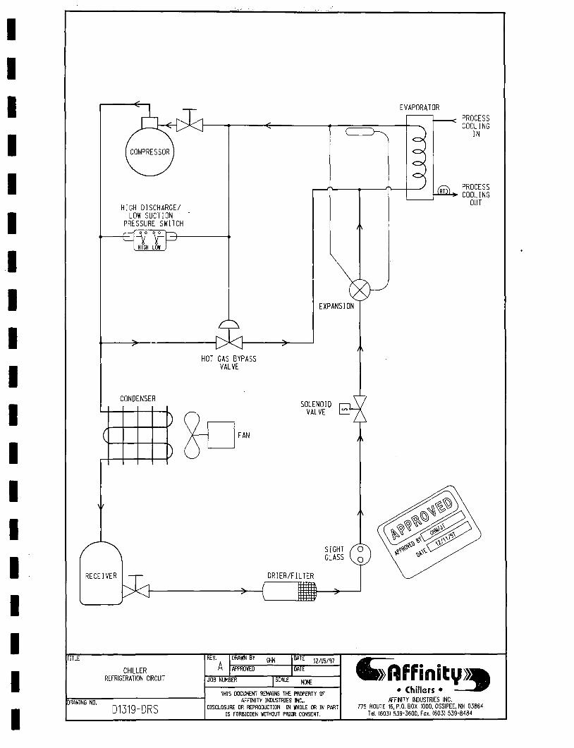
EVAPORATOR
HIGH DISCHARGE/ LOW SUCTION
PRESSURE SWITCH
e ^ ° ^ Hliai LOl J
-^ ^
EXPANSION
HOT GAS BYPASS VALVE
CONDENSER
( .
)
)
SOLENOID VALVE
FAN
RECEIVER
^
. ^ PROCESS COOLING
IN
(m)^ PROCESS COOLING
OUT
REVT DRAWN BY rar" TITLE
CHILLER REFRIGERATION CIRCUIT
DRAWING NO,
D1319-DRS
GUM
APPROVED
JOB NUMBER
12/15/<17
DATE
SCALE NONE
THIS DOCUMENT REMAINS THE PROPERTY OF AFFINITY INDUSTRIES INC.
DISCLOSURE OR REPRODUCTION IN WHOLE OR IN PART IS FORBIDDEN WITHOUT PRIOR CONSENT.
•»nfFinitv»] Chillers
/AFFINITY INDUSTRIES INC. 7 7 5 ROUTE 16, P.O. BOX 1000. OSSIPEE, NH 0 3 8 6 4
Tel. (603) 539-3600, Fax. (603) 539-8484
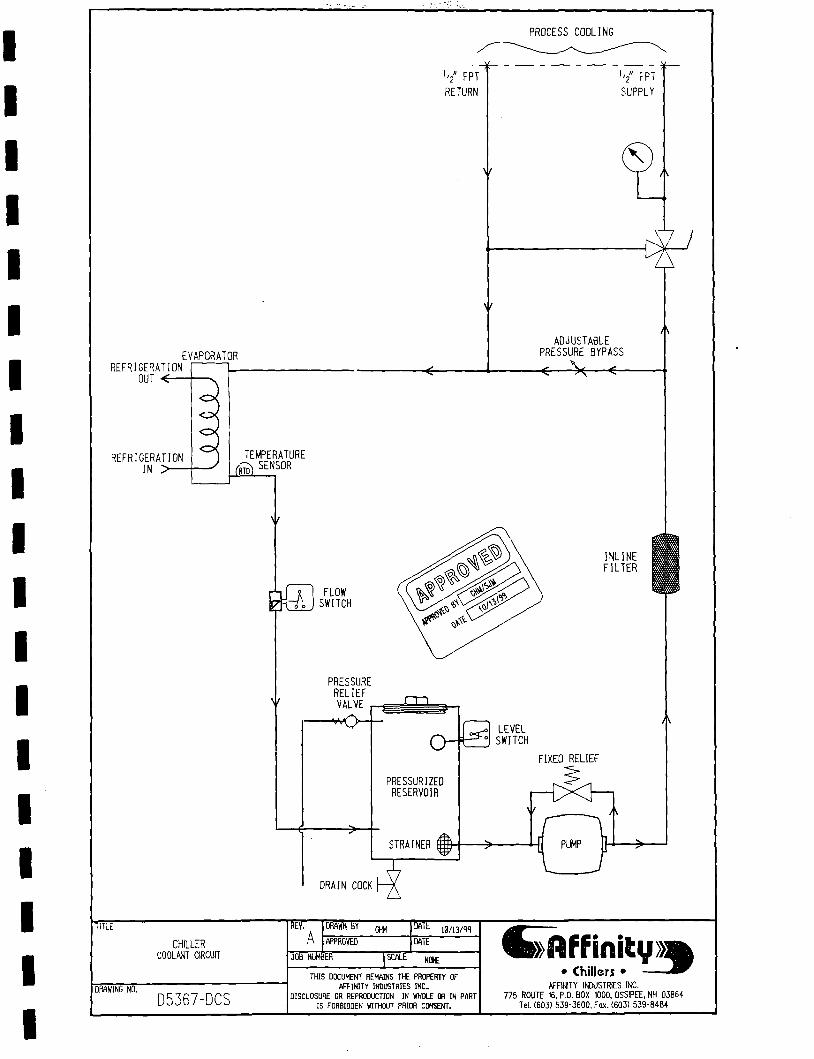
PROCESS COOLING
I// FPT RETURN
REFRIGERATION OUT < -
EVAPORATOR
REFRIGERATION IN >
'2" FPT SUPPLY
ADJUSTABLE PRESSURE BYPASS
• V
TEMPERATURE ;;; SENSOR
m FLOW SWITCH
INLINE FILTER
PRESSURE RELIEF VALVE
0-& PRESSURIZED RESERVOIR
STRAINER
LEVEL SWITCH
FIXED RELIEF
DRAIN COCK
m-TITLE
CHILLER COOLWIT CIRCUIT
D.'MWING NO,
D5367-DCS
REVT DRAWN B Y ^
APPROVED
JOB NUMBER
la/ia/'w
DATE
SCALE HOC
THIS DOCUMENT REMAINS THE PROPERTY OF AFFINITY INDUSTRIES I N C
DISCLOSURE OR REPROOUCnON IN WHOLE OR IN PART IS FDRBIDDEN WITHOUT PRIOR CONSENT.
^»nFFmiCv»] • Chillers •
AFFINITY INDUSTRIES INC. 775 ROUTE 16, P.O. BOX 1000, OSSPEE, NH 0 3 8 6 4
Tel. (603) 539-3600, Fax. (603) 539-8484

208-230 VaT. SINGLE PHASE, 60 Hz. 200 VOLT. SINGLE PHASE. 50 Hz.
( D 1 NEMA 6-15P
D
LEGEND:
WIRE COLORS - P R W A R Y COLOR/TRACER OR MARKER COLOR
( D • COlilPONENT TER l iHAL
D • lERliJNAL BLOCK
AR • ALARliI RELAY
CON - I B T O R CONTACTOR
CT - CONTROL TRANSFORMER
CR • CONTROL RELAY
FU - FUSE
OL • l/OTOR OVERLOAD PROTECTION
TC - l E l f ERATURE CONTROLLER
- U -
^ ^N^4 L4\J ( PUMPJ
( IHEN USED)
CONNECT FOR SYSTEM VOLTAGE 1
-^ t :^ i_.
g" Ti^ ( LOW SUCTION/ ~ ^ I HIGH DISCHARGE PRESS I
1 ® Q 5 ^ A ® ® 0
Q ^ & r
TCl G ) ^
/ TFUPCPATIIRF
TtL/BED g ) /
TEMPERATURE CONTROLLER
SSRl
Afl2 jnrBLMKT
LEva ©.£
.0gD/tuj 25 PIN ^ ' D-SUBMINIATURE
RECEHAaE
TEL/BCK ® ^ «"/«'
MTIli THIS coKTitn 9 T v s s i BE F n o c n M e s NtnNftLY OPEN CH NORMULLY CLOSED FIB HICH m L0» TF1»fI»TlBF LIKTT
•^aow
( La i_ JHW
l2!^,f l^,^«2!l^\j5_JS0^,
P U B LOW LEVEL P I , „
— ^ — o 1-0 y iw H
n ^41^ 1
LOW L E V E L
^
^
LOW FLOW
PIJ e LOW FLOW PIN m
JUI1_
• ^ ^
^ ' ^
«"^ 0®—^ R E F R I G E R A T I O N
SOLENOID PIM «I0 k PIN #7
TiTTT DRAWN BY wr DES ELECTRICAL SCHEMATIC
208-230 VOLT, SINGLE PHASE, 60 Hz.
200 VOLT, SINGLE PHASE, 50 Hz. 2 5 P I N INTERLOCK
D E W I N G NO,
D7013
DTT
APPROVED
JOB NUMBER
I/17/0I
DATE
SCALE HONE
THIS DOCUMENT REMAINS THE PRIPERTY OF AFFINITY INDUSTRIES I N C
DISCLOSURE OR REPRODUCTION IN WHOLE OR IN PART IS FORBIDDEN WITHOUT PRIOR CONSENT.
^hf f in i tv » :
Chillers • AFFINITY INDUSTRIES INC.
775 ROUTE 15, P.O. BOX 1000, OSSIPEE, NH 03B64
Tel. (603) 539-3600, Fox. (603) 539-8484