webfield jx-300xp - 2.imimg.com · webfield jx-300xp system 7-8 major technical data working...
TRANSCRIPT
WebField JX-300XP
Selection Manual

WebField

JX-300XP
About SUPCON
SUPCON Group Co., Ltd. (SUPCON for short) is one of the most
famous Chinese suppliers on automation & information technology,
products and solutions. SUPCON's business includes process
automation, public works automation, equipment automation, etc.
As one of the largest suppliers of process automation in China,
SUPCON's business has spread over China, Vietnam, Pakistan,
Sudan, Myanmar, Thailand, India, Egypt, Kazakhstan, Indonesia,
Canada, etc.
SUPCON's products include DCS systems, instruments,
optimization and advanced control software, which have played an
important role in various process industries such as Chemical,
Fertilizer, Petrochemical, Power, Mining & Metallurgy, Building
Material, Brewing, Pulp & Paper, Oil & Gas, Pharmaceutical, etc.
1-2
WebField
JX-300XP 3-4
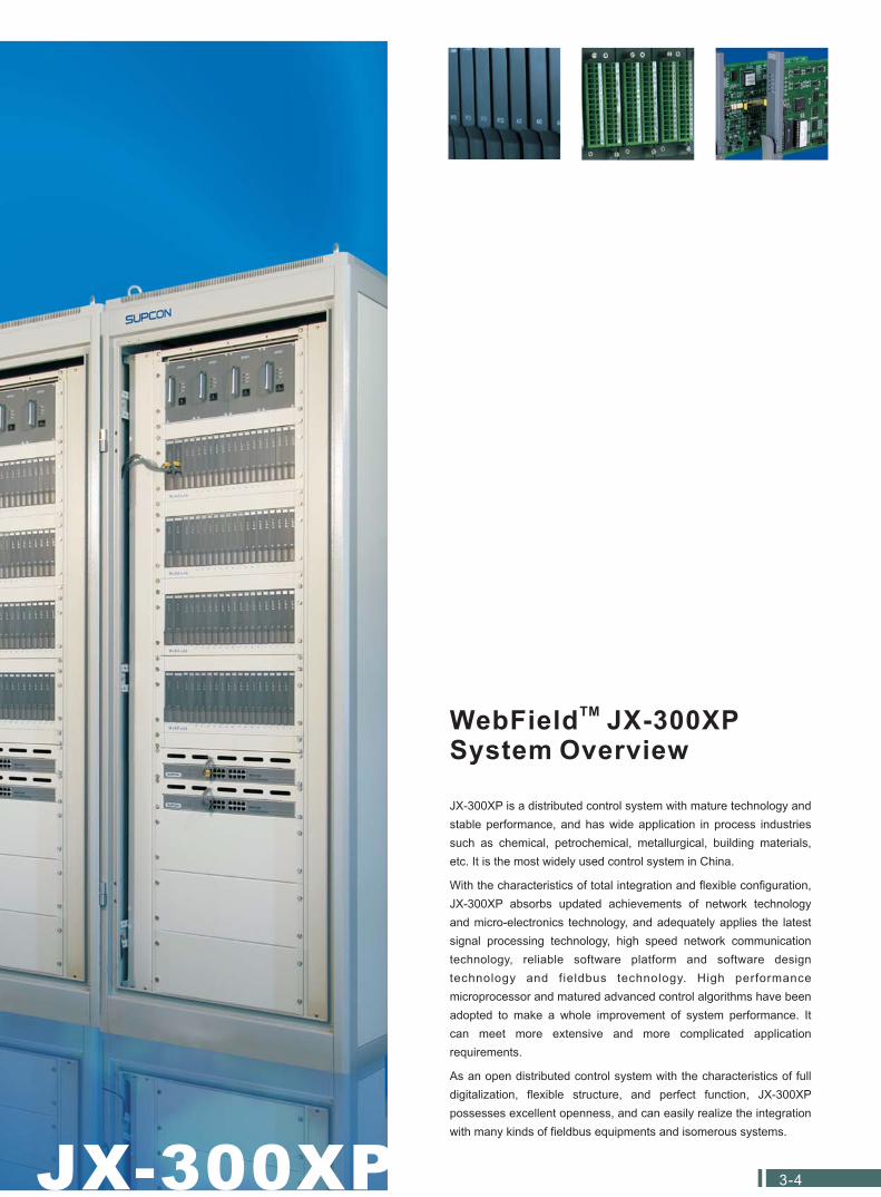
WebField JX-300XPSystem Overview
TM
JX-300XP is a distributed control system with mature technology and
stable performance, and has wide application in process industries
such as chemical, petrochemical, metallurgical, building materials,
etc. It is the most widely used control system in China.
With the characteristics of total integration and flexible configuration,
JX-300XP absorbs updated achievements of network technology
and micro-electronics technology, and adequately applies the latest
signal processing technology, high speed network communication
technology, reliable software platform and software design
technology and fieldbus technology. High performance
microprocessor and matured advanced control algorithms have been
adopted to make a whole improvement of system performance. It
can meet more extensive and more complicated application
requirements.
As an open distributed control system with the characteristics of full
digitalization, flexible structure, and perfect function, JX-300XP
possesses excellent openness, and can easily realize the integration
with many kinds of fieldbus equipments and isomerous systems.
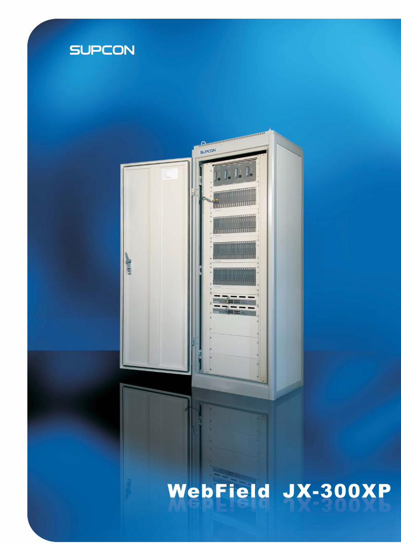
WebField JX-300XP
5-6
PAGE
System Structure 7
Major Technical Data
Working Environment
Requirement of Power Supply
Grounding Requirement
System Scale
Control Station Scale
Introduction
Network Structure
Mechanical Components
Cabinet
Operation Desk
Printer Desk
Control Station Components
Rack
Power Supply Module
Power Supply Rack
General View of I/O Modules
Controller
Date Transmission Module
I/O Modules of Control Station
Analog Input Module
Voltage Input Module
Thermo Resistance (RTD) Signal Input Module
Pulse Signal Input Module
PAT Module (Position Adjustment Type Module)
Analog Signal Output Module
Voltage-level Digital Input Module
Contact Digital Input Module
SOE Signal Input Module
Transistor Digital Output Module
Terminal Components
General View of Terminal Components
I/O Terminal Board (non-redundant)
Redundant Terminal Board
DI/DO Terminal Board Conversion Module
DI/DO Terminal Board
8
8
9
8
8
9
11
1 1
12
1213
14
14
15
15
16
17
18
19
20
21
21
22
22
23
23
23
23
24
24
Hardware of Operation Station
Host Computer of Operation Station
Report Printer (Optional)
25
Network Components
Communication Interface Module
Swith
Electric Repeater
Fiber Repeater
26
26
26
27
27
System Software
Operating System
28
Application Software
System Configuration Software
Graphics Configuration Software
Graphic Control Language Software
Language Configuration Software
Report Configuration Software
Real-time Monitor Software
29
29
29
29
30
30
30
10
CONTENTS
The Structure of JX-300XP System
Overview
Network Structure
www.supcon.com/en
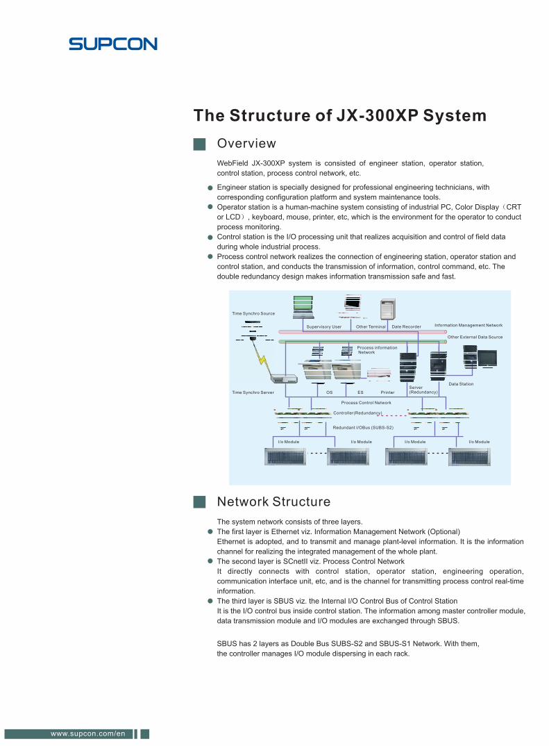
WebField JX-300XP system is consisted of engineer station, operator station,
control station, process control network, etc.
Engineer station is specially designed for professional engineering technicians, with
corresponding configuration platform and system maintenance tools.
Operator station is a human-machine system consisting of industrial PC, Color Display CRT
or LCD , keyboard, mouse, printer, etc, which is the environment for the operator to conduct
process monitoring.
Control station is the I/O processing unit that realizes acquisition and control of field data
during whole industrial process.
Process control network realizes the connection of engineering station, operator station and
control station, and conducts the transmission of information, control command, etc. The
double redundancy design makes information transmission safe and fast.
SBUS has 2 layers as Double Bus SUBS-S2 and SBUS-S1 Network. With them,
the controller manages I/O module dispersing in each rack.
The system network consists of three layers.
The first layer is Ethernet viz. Information Management Network (Optional)
Ethernet is adopted, and to transmit and manage plant-level information. It is the information
channel for realizing the integrated management of the whole plant.
The second layer is SCnetII viz. Process Control Network
It directly connects with control station, operator station, engineering operation,
communication interface unit, etc, and is the channel for transmitting process control real-time
information.
The third layer is SBUS viz. the Internal I/O Control Bus of Control Station
It is the I/O control bus inside control station. The information among master controller module,
data transmission module and I/O modules are exchanged through SBUS.
Time Synchro Source
Supervisory User Other Terminal Date Recorder Information Management Network
Other External Data Source
Time Synchro Server
I/o Module I/o Module
Controller(Redundancy)
I/o Module
OS ES Printer
Data Station
Redundant I/OBus (SUBS-S2)
I/o Module
Server(Redundancy)
Process Control Network
Process informationNetwork
WebField JX-300XP system
7-8
Major Technical Data
Working Environment
Control station: Dual redundancy power supply, 220VAC 10% 50Hz 5
maximum 800W.Power Factor Correction (according to IEC61000-3-2 standard).
Operator station, engineering station and multi-function station: 220VAC 10% 50Hz 5
maximum 400W.
Requirement of Power Supply
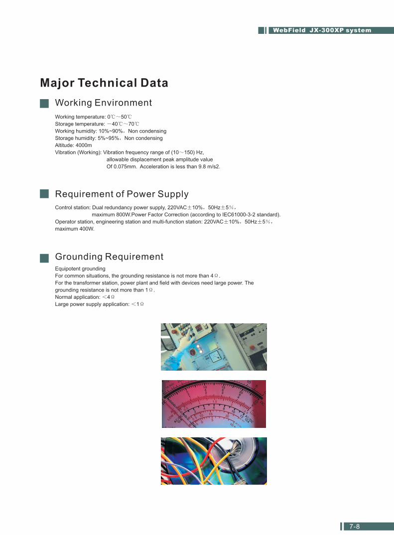
Grounding RequirementEquipotent grounding
For common situations, the grounding resistance is not more than 4 .
For the transformer station, power plant and field with devices need large power. The
grounding resistance is not more than 1 .
Normal application: 4
Large power supply application: 1
Working temperature: 0 50
Storage temperature: 40 70
Working humidity: 10%~90% Non condensing
Storage humidity: 5%~95% Non condensing
Altitude: 4000m
Vibration (Working): Vibration frequency range of (10 150) Hz,
allowable displacement peak amplitude value
Of 0.075mm. Acceleration is less than 9.8 m/s2.
The maximum system configuration includes 15 redundant control stations and 32
operator stations or engineer stations, with maximum system capability of 15,360
nodes.
Major Technical Data
System Scale
AI (analog input) point <=384 (including pulse input) per station
AO (analog output) point <=128 per station
DI (digital input) point <=1024 per station
DO (digital output) point <=1024 per station
Control loop: 128 per station (The sum of BSC and CSC cannot exceed
64; The regular control loop cannot exceed 64)
Program space: 4Mbit Flash RAM
Data space: 4Mbit SRAM
1-byte variable (virtual digital) <=2048 (internal digital contact point)
2-byte variable <=2048 (int, sfloat)
4-byte variable <=512 (long, float)
8-byte variable <=256 (sum)
256 second timers and 256 minute timers
Control Station Scale
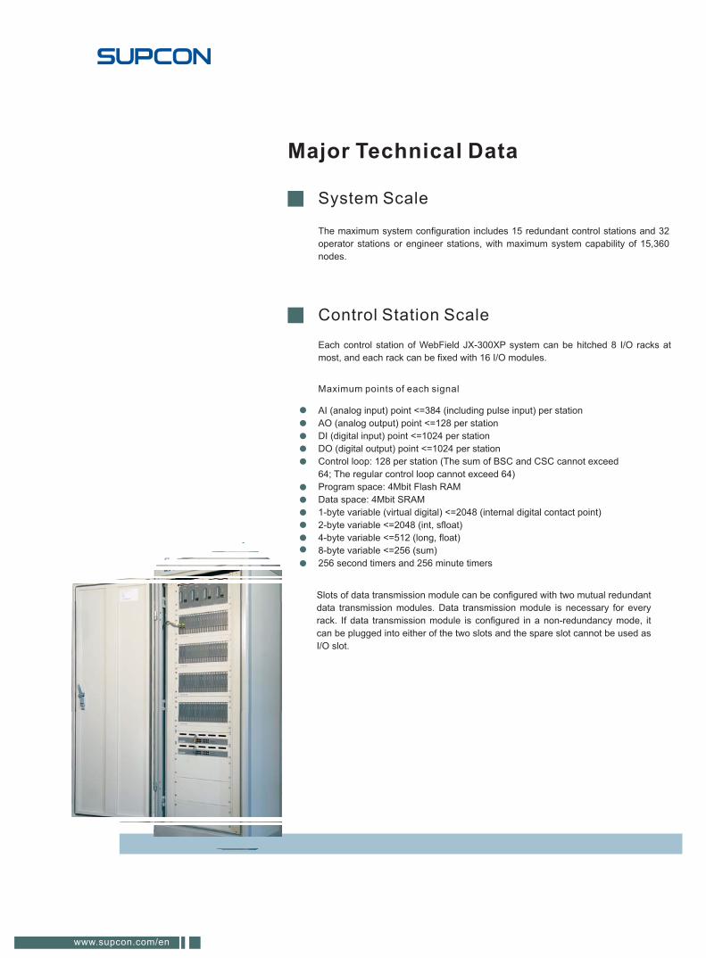
Slots of data transmission module can be configured with two mutual redundant
data transmission modules. Data transmission module is necessary for every
rack. If data transmission module is configured in a non-redundancy mode, it
can be plugged into either of the two slots and the spare slot cannot be used as
I/O slot.
Each control station of WebField JX-300XP system can be hitched 8 I/O racks at
most, and each rack can be fixed with 16 I/O modules.
Maximum points of each signal
www.supcon.com/en
WebField JX-300XP system
9-10
Mechanical Components
Cabinet
Operation Desk
Printer Desk (Optional)
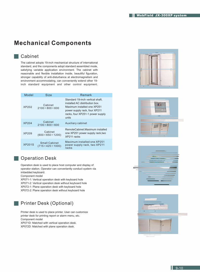
The cabinet adopts 19-inch mechanical structure of international
standard, and the components adopt standard assembled mode,
satisfying variable application environment. The cabinet with
reasonable and flexible installation inside, beautiful figuration,
stronger capability of anti-disturbance at electromagnetism and
environment accommodating, can conveniently extend other 19-
inch standard equipment and other control equipment.
Model Size Remark
Cabinet2100 800 600
Cabinet( )600 650 1200
Small Cabinet( )715 425 1000
XP202
XP204 Auxiliary cabinet
XP209
XP201S
Cabinet2100 800 600
Standard 19-inch vertical shaft,
installed AC distribution box.
Maximum installed one XP251
power supply rack, four XP211
racks, four XP251-1 power supply
units
RemoteCabinet.Maximum installed
one XP251 power supply rack,two
XP211 racks
Maximum installed one XP251power supply rack, two XP211racks
Operation desk is used to place host computer and display of
operator station. Operator can conveniently conduct system via
imbedded keyboard.
Component model
XP071-1: Vertical operation desk with keyboard hole
XP071-2: Vertical operation desk without keyboard hole
XP072-1: Plane operation desk with keyboard hole
XP072-2: Plane operation desk without keyboard hole
Printer desk is used to place printer. User can customize
printer desk for printing report or alarm menu, etc.
Component model
XP071D: Matched with vertical operation desk.
XP072D: Matched with plane operation desk.
Control Station Components
Rack
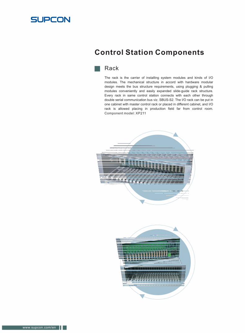
Component model: XP211
The rack is the carrier of installing system modules and kinds of I/O
modules. The mechanical structure in accord with hardware modular
design meets the bus structure requirements, using plugging & pulling
modules conveniently and easily expanded slide-guide rack structure.
Every rack in same control station connects with each other through
double serial communication bus viz. SBUS-S2. The I/O rack can be put in
one cabinet with master control rack or placed in different cabinet, and I/O
rack is allowed placing in production field far from control room.
www.supcon.com/en
Power Supply Module
Power Supply Rack
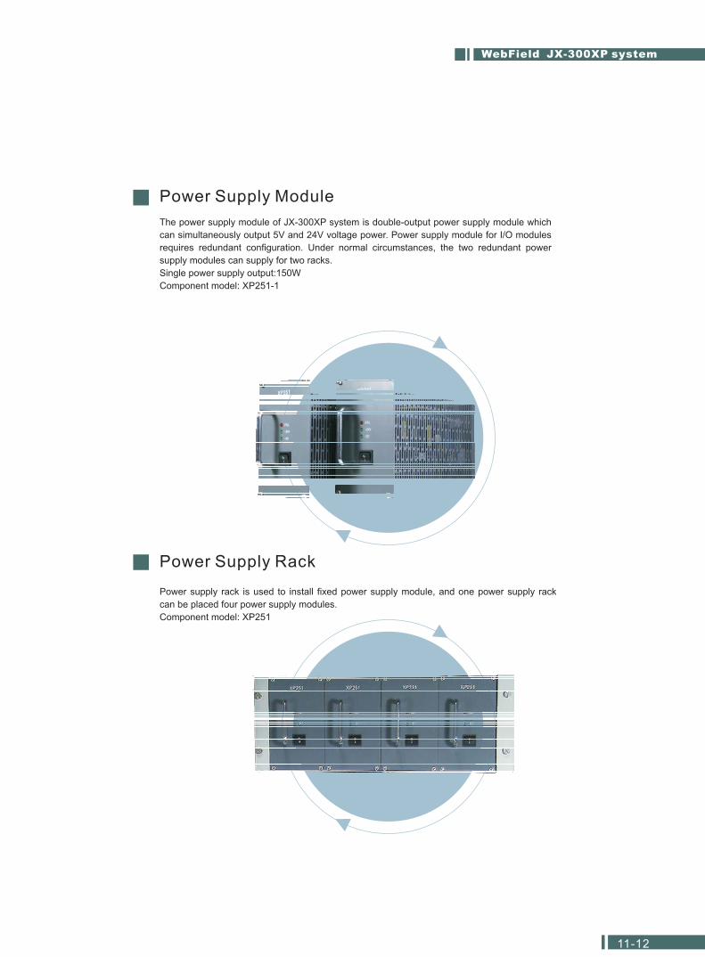
The power supply module of JX-300XP system is double-output power supply module which
can simultaneously output 5V and 24V voltage power. Power supply module for I/O modules
requires redundant configuration. Under normal circumstances, the two redundant power
supply modules can supply for two racks.
Single power supply output:150W
Component model: XP251-1
Power supply rack is used to install fixed power supply module, and one power supply rack
can be placed four power supply modules.
Component model: XP251
WebField JX-300XP system
11-12
General View of I/O Modules
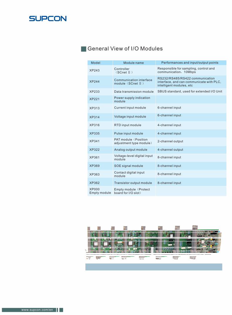
Model Module name Performances and input/output points
XP243Controller
SCnet
Responsible for sampling, control andcommunication 10Mbps
XP244Communication interfacemodule SCnet
RS232/RS485/RS422 communicationinterface, and can communicate with PLC,intelligent modules, etc
XP233 Data transmission module SBUS standard, used for extended I/O Unit
XP313 Current input module 6-channel input
XP314 Voltage input module 6-channel input
XP316 RTD input module 4-channel input
XP335 Pulse input module 4-channel input
XP341PAT module Positionadjustment type module
2-channel output
XP322 Analog output module 4-channel output
XP361Voltage-level digital inputmodule
XP362 Transistor output module 8-channel input
XP363Contact digital inputmodule
8-channel input
XP369 SOE signal module
8-channel input
XP221 Power supply indicationmodule
XP000Empty module
Empty module Protectboard for I/O slot
8-channel input
www.supcon.com/en
Controller
Controller
ontroller
is the core of control station, in charge of regulating all relations of
hardware and software inside control station and all kinds of control tasks, such
as I/O signal handling, calculation control, communication control and handling
between upper and lower layers network, redundant diagnosis, etc.
Adopt double-CPU structure, which are main CPU (Master) and CPU (Slave).
Support redundancy and non-redundancy configuration and the mode of
redundancy is 1:1 hot standby.
The number of control loops can be up to 128 (Sum of self-defined BSC and
CSC can’t exceed 64 at most, and sum of regular BSC and CSC can’t exceed
64 at most.)
Support 128 I/O modules at most and realize local or remote I/O control function
through SBUS.
Internal backup LI-battery, used to protect SRAM date (including system
configuration, control parameter, running status, etc.) Inside c
after powered down, improving system’s safety and maintenance. When system
is power off, SRAM date can be kept up to 3 months for the longest time.
Necessary module for every control station
Component model: XP243
Date Transmission Module
In charge of data exchange between master control module and I/O modules, it is
the necessary module of each rack.
Function of WDT watchdog reset.
Support redundancy structure and non-redundancy working.
Conduct self-check to power supply status of the rack.
Acquire cold-side temperature and check environment temperature.
Realize remote connection of bus nodes through repeater.
Support communication of high speed redundant SBUS.
Component model: XP233
WebField JX-300XP system
13-14
Analog input module can measure 6-channel signal (II type or III type), and offer +24V isolated
power distribution for 6-channel transmitter. It is the intelligent module fixed with CPU that can
condition and measure analog input signal, possessing the function of inspection and
communication with master controller.
I/O Modules of Control Station
Analog Input Module
Module Technical Data
Model XP313
Power supply
24V power supply 24 0.5 VDC Imax<200mA
Input loop
Signal typeCurrent signal (type II or type III),configuration selected
Isolation mode Photoelectricity isolation,group isolation
Isolated voltage
500VAC one minute (field sideand system side)
250VAC one minute(betweengroups)
Short circuitprotection
<30mA (single module,each channel)
Open circuitsinspection
Type II signal with this function,type III signal without this function
5V power supply 5 0.3 VDC Imax<50mA
Channel 6-channel
Filter time configuration selected
Resolution 15 bit, polarity
Input impedance 250
Common- moderejection ratio 100dB
Series-moderejection ratio
>50dB
Loading capacity 1k (20mA)
Measuring Range and Precision
Standard current (type II) 0 10 mA 0.2%FS
Standard current (type III) 4 20 mA 0.2%FS
Signal type Measuring range Precision
www.supcon.com/en
Voltage signal input module is the intelligent 6-channel analog signal acquisition one with analog
conditioning function. Each channel can be configured independently and receive kinds of
thermocouple and voltage signal, after conditioning they are transformed to digital signal and
transmitted to controller by data transmission module.
Voltage Input Module
Module Technical Data
Measuring Range and Precision
Type of input signal Measuring range Precision Other
B type thermocouple 0 1800 0.2 FS
E type thermocouple -200 900 0.2 FS
J type thermocouple -40 750 0.2 FS
K type thermocouple -200 1300 0.2 FS
S type thermocouple 200 1600 0.2 FS
T type thermocouple -100 400 0.2 FS
MV 0 100 mV 0.2 FS
MV 0~20 mV 0.2 FS
Standard voltage 0~5 V 0.2 FS
Standard voltage 1~5 V 0.2 FS
cold junction compensative error 1
5V power supply
24V power supply
Channel
Signal type
Filter time
Resolution
Input impedance
Isolation mode
Isolated voltage
Common- moderejection ratio
Series-moderejectionratio
Open circuitsinspection
Model
6-channel
Voltage and thermocouple signal,configuration selected
Configuration selected
15 bit, polarity
1M
Photoelectricity isolation,Group isolation
500VAC one minute (field sideand system side)
250VAC one minute (between groups)
Large signal>100dB ,small signal>130dB
Large signal>50dB ,small signal>60dB
Open circuits inspection fuctionfor thermocouple signal
5 0.3 VDC Imax<30mA
24 0.5 VDC Imax<30mA
XP314
Module power
Input loop
WebField JX-300XP system
15-16
Thermo resistance signal input module is the intelligent redundant 4-channel A/D transforming one
specialized in measuring RTD signal. Each channel can be independently configured and receive
RTD signal of Pt100 or Cu50, after conditioning they are transformed to digital signal and
transmitted to controller by data transmission module.
Thermo Resistance(RTD) Signal Input Module
Module Technical Data
Model XP316
Module power
24V power supply 24 0.5 VDC Imax<30mA
Input loop
Signal type
Isolation modePhotoelectricity isolation,group isolation
Isolated voltage
500VAC one minute (field sideand system side)
250VAC one minute (betweengroups)
Open circuitsinspection
5V power supply 5 0.3 VDC Imax<35mA
Channel 4-channel
Filter time Configuration selected
Resolution 15 bit, polarity
Input impedance 1M
Common- moderejection ratio 110dB
Series-moderejection ratio
>40dB
Thermocouple signal,configuration selected
It possesses open circuitsinspection function.
Measuring range and precision
Type of input signal Measuring range Precision
Pt100 RTD -148 850 0.2 FS
Cu50 RTD -50 150 0.5 FS
www.supcon.com/en
Pulsed signal input module can satisfy the majority of applications of the patch of pulse
measurement module. Every piece of module can measure 4-channel three-wire or two-wire of pulse
signal from 1 Hz to 10K Hz, and divided into two groups, which is isolated by group. Low-level is
from 0 to 2 V, and high lever is from 5 to 30 V.
Pulse Signal Input Module
Module Technical Data
Model XP335
Module power
24V Power supply 24 0.5 VDC Imax<200mA
Input loop
Signal type
Module powerdistribution
Isolated voltage500VAC one minute (field side and system side)
250VAC one minute (between groups)
5V Power supply 5 0.3 VDC Imax<120mA
Channel 4-channel
Resolution
Measuring range
Waveform of signal types: square wave, sine wave
High lever: 5 30 V Low-level 0 2 V
1Hz
1Hz~10kHz
24V Imax=45mA
Isolation mode Photoelectricity isolation, group isolation
Measuring mode three-wire or two-wire
Conversion time
5Hz~10KHz
1Hz~5Hz
200ms
200ms~1s
WebField JX-300XP system
17-18
Position adjustment type module viz. PAT module is used mostly in control
electromotion unit. Every channel is composed of 2-channel digital variable input, 2-
channel digital variable output and one channel analog input .2-channel digital variable
input that are used for alarm of limit of positive and negative, and one channel analog
input is used to import position feedback; 2-channel digital variable output which are
used to control motor positive rotation or motor negative rotation. There is
concatenation protection between the positive and negative limit position alarm input
and driven-output. When the valve reaches the limit position (Need to connect feedback
signals of valve limit position into the corresponding DI input of PAT module),
immediately cut off output control In order to protect motors. The modules are high
control precision.
PAT Module (Position Adjustment Type Module)
Module Technical Data
Model XP341
Module power
24V Power supply 24 0.5 VDC Imax<120mA
Input loop
Isolated voltage500VAC one minute (field side and system side)
250VAC one minute (between groups)
5V Power supply 5 0.3 VDC Imax<100mA
Channel 2-channel
Feedback signal typeCurrent/Input impedance
Resistance 1k Need customization
4~20 mA/100
The precision of feedbacksignal 0.3%FS
Digital variable output <1k ONAlarm >100k OFF
Output 24V output(15mA source current)
Control precision
Isolation mode
Common- mode rejection ratio >100dB
Series-mode rejection ratio >50dB
Open circuits inspection
Depending on the different valves(less than dead-zone)
Photoelectricity isolation, group isolation
It possesses open circuits inspection function
www.supcon.com/en
Analog signal output module is the 4-channel current output one isolated by
point (type II or type III). As the intelligent module with high precision fixed with
CPU, it possesses real-time output signal inspection function, and permit
controller monitoring current output.
Analog Signal Output Module
Module Technical Data
Model XP322
Module power
24VPower 24 0.7 VDC Imax<200mA
Input loop
5VPower 5 0.3 VDC Imax<50mA
Channel 4-channel
Signal type
Resolution 12 bits, non-polarity
Precision 0.2 FS
II type 0 10 mA
III type 4 20 mA
Type II signal 0 10mA 2K
Type III signal 4 20mA 1K
Type II signal 0 10mA
Type III signal 4 20mA 750Output loadingcapacity
LOW
HIGH
WebField JX-300XP system
19-20
Voltage Digital Input Module
Voltage-level digital input module is 8-channel digital signal input module, and can
fast response to voltage-level digital input. It adopts photoelectric isolation to
achieve the accurate digital signal acquisition. Module has self-diagnosis function
(including inspection to working state of digital input channel). External voltage can
choose 48VDC or 24 VDC.
Module Technical Data
Model XP361
Module power
24V Power supply 24 0.5 VDC Imax<15mA
Input loop
5V Power supply 5 0.3 VDC Imax<60mA
Channel 8-channel
Signal type Signal Lever
Filter time 10ms
Logic 0 value of input valve 0~5 V
Logic 1 value of input valve 12~54 V
Isolation modePhotoelectricity isolation, groupingisolation
Isolated voltage 500VAC one minute (field sideand system side)
Contact digital input module is the 8-channel contact digital input intelligent module.
It adopts photoelectric isolation, possesses function of output inspection to itself. It
offers isolation of 24V/48V DC detecting voltage.
Contact Digital Input Module
Module Technical Data
Model XP363
Module power
24V Power supply 24 0.5 VDC Imax<25mA
Input loop
5V Power supply 5 0.3 VDC Imax<60mA
Channel 8-channel
Signal type
Filter time 10ms
Isolation mode Photoelectricity isolation, module isolation
Isolated voltage 500VAC one minute (field side and system side)
Dry contact input (common grounding)
Logic ON input <1k
Logic OFF input >100k
Detecting voltage 24V or 48V (optional)
www.supcon.com/en
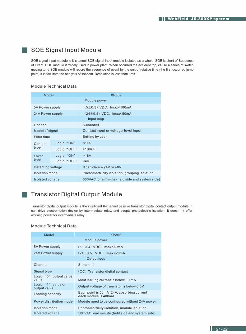
SOE signal input module is 8-channel SOE signal input module isolated as a whole. SOE is short of Sequence
of Event. SOE module is widely used in power plant. When occurred the accident trip, cause a series of switch
moving ,and SOE module will record the sequence of event by the unit of relative time (the first occurred jump
point).It is facilitate the analysis of incident. Resolution is less than 1ms.
Transistor digital output module is the intelligent 8-channel passive transistor digital contact output module. It
can drive electromotion device by intermediate relay, and adopts photoelectric isolation. It doesn t offer
working power for intermediate relay.
SOE Signal Input Module
Module Technical Data
Model XP369
Module power
24V Power supply 24 0.5 VDC Imax<50mA
Input loop
5V Power supply 5 0.3 VDC Imax<100mA
Channel 8-channel
Model of signal
Filter time
Contact input or voltage-level input
Setting by user
Logic ON <1k
Logic OFF >100k
Logic ON >18V
Logic OFF <4V
Isolation mode Photoelectricity isolation, grouping isolation
Isolated voltage 500VAC one minute (field side and system side)
Detecting voltage It can choice 24V or 48V
Contacttype
Levertype
Transistor Digital Output Module
Module Technical Data
Model XP362
Module power
24V Power supply 24 0.5 VDC Imax<20mA
Output loop
5V Power supply 5 0.3 VDC Imax<60mA
Channel 8-channel
Signal type
Isolation mode Photoelectricity isolation, module isolation
Isolated voltage 500VAC one minute (field side and system side)
OC Transistor digital contact
Logic 1 value ofoutput valve
Output voltage of transistor is below 0.3V
Logic 0 output valvevalue Most leaking current is below 0.1mA
Loading capacity Each point is 50mA (24V, absorbing current),each module is 400mA
Power distribution mode Module need to be configured without 24V power
WebField JX-300XP system
21-22
Terminal Components
General View of Terminal Components
Model Name of component Unit Remark
XP520 I/O Terminal board (non-redundant) PieceUniversal I / O non-redundant terminalmodule, and place in the back of rack
XP520R I/O Terminal board (redundant) PieceUniversal I / O redundant terminal module,and place in the back of rack
XP521 DI/DO terminal board conversion module PieceDI/DO terminal board conversion module,and place in the back of rack
XP562-GPR 16-channel mechanical relay outputterminal board
Piece 16-channel, two modules are correspondingto one terminal board
XP563 110V16-channel 110V AC digital inputterminal board Piece
16-channel, two modules are correspondingto one terminal board
XP563 220V16-channel 220V AC digital inputterminal board
Piece16-channel, two modules are correspondingto one terminal board
XP563 GPR16-channel Universal relay isolated digitalinput terminal board
Piece16-channel, two modules are correspondingto one terminal board
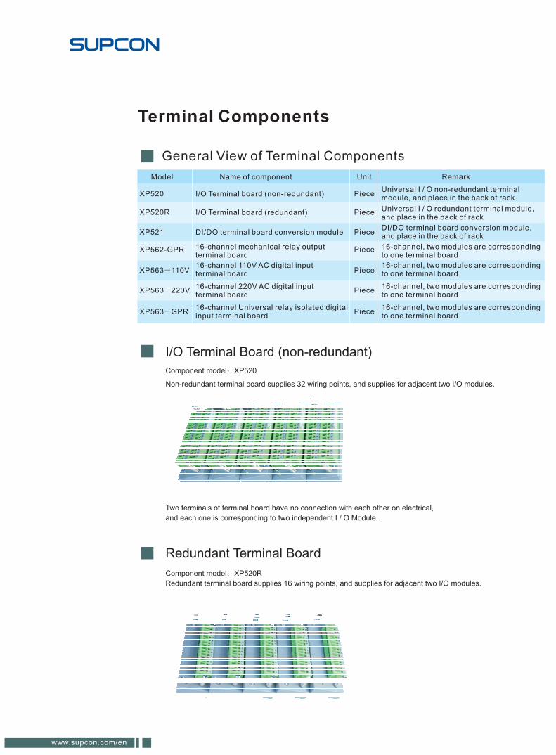
I/O Terminal Board (non-redundant)
Component model XP520
Non-redundant terminal board supplies 32 wiring points, and supplies for adjacent two I/O modules.
Two terminals of terminal board have no connection with each other on electrical,
and each one is corresponding to two independent I / O Module.
Component model XP520R
Redundant terminal board supplies 16 wiring points, and supplies for adjacent two I/O modules.
Redundant Terminal Board
www.supcon.com/en
Component model XP521
Terminal board conversion module is implementing the conversion of XP562,
XP563 DI / DO signal through special signal connecting line.
DI/DO Terminal Board Conversion Module
DI/DO Special Terminal BoardNo special requirements for the DI / DO signal. Systems provide a special terminal
board to implement the isolation and simple installation of beside site and system,
including 16-channel 220V AC digital input terminal board XP563-110V
16-channel 110V AC digital input terminal board XP563-GPR,
16-channel Universal relay isolated digital input terminal board and 16-channel
mechanical relay output terminal board XP562-GPR.
WebField JX-300XP system
23-24
Hardware of Operation Station
Host Computer of Operation Station
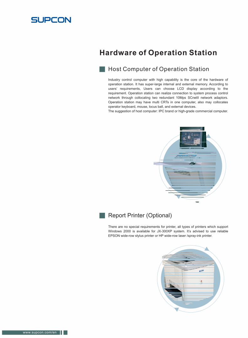
There are no special requirements for printer, all types of printers which support
Windows 2000 is available for JX-300XP system. It’s advised to use reliable
EPSON wide-row stylus printer or HP wide-row laser /spray-ink printer.
Industry control computer with high capability is the core of the hardware of
operation station. It has super-large internal and external memory. According to
users’ requirements, Users can choose LCD display according to the
requirement. Operation station can realize connection to system process control
network through collocating two redundant 10Mps SCnetII network adaptors.
Operation station may have multi CRTs in one computer, also may collocates
operator keyboard, mouse, locus ball, and external devices.
The suggestion of host computer: IPC brand or high-grade commercial computer.
Report Printer (Optional)
www.supcon.com/en
Network Components
Component model
Component model XP244 XP239 Communication interface module is the core of
communication interface unit, solving interlinkage of JX-300XP system with other
manufactures’ intelligent equipment. It is interlinkage users’ intelligent system of data
through the method of communication into the JX - 300XP systems, through SCnet II
network data to implement JX - 300XP systems sharing.
The application of communication interface module solves some external
equipment’s communication with DCS system, and DCS system can facilitate
communication with some manufactures’ intelligent equipment. It has realized
interlinkage of ModBus-RTU,HostLink-ASCII of communication protocol with some
intelligent equipments of open communication protocol.
Switch is the communication equipment of SCnet II which is linking operatingstation computers with controller of control station. It is a unit networkmanagement. According to the network scale, users can choose the sharingHUB or exchange HUB.
Communication Interface Module
Switch
Sup-2118M
DES-1016R+
Sup-2118M
DES-1016R+
DES-1016R+
DES-102F SC
DES-102F
F-02
10M/100M switch with fiber interface
10M/100M switch
Name Unit
Piece
Piece
Piece
Piece
Piece
16 pieces of RJ45 interfaces
16 pieces of RJ45 interfaces
16 pieces of RJ45 interfaces,with one piece of fiber module
16 pieces of RJ45 interfaces,with one piece of fiber module
16 pieces of RJ45 interfaces,with two pieces of fiber module
Remark
WebField JX-300XP system
25-26
Component model XP022
In the long-distance data transmission, signals would happen with
attenuation and distortion. When remote communication interface device
can not tell the attenuation of signal, communication will be un-normal or
communications failure. The solution is adding a first-class repeater before
the transmission limit distance. It will enlarge the attenuation signal through
the repeater, and achieve the purpose of increasing the transmission
distance.
Electric Repeater can be used to process communications network SCnet II
or internal communication bus (SBUS). It can implement the electric
isolation and failure isolation with two ends of repeater, and improve the
reliability of network.
Component model XP433M (for SBUS network)
It needs add fiber transfer box.
Process communication network SCnet II with optical switch of fiber
extension module can realize fiber repeaters .
Electric Repeater
Fiber Repeater
www.supcon.com/en
System Software
Windows 2000/XP + SP4
Operating System
Application software package
Composition of software package
AdvanTrol Real-time Monitor Software
SCKey System Configuration Software
SCLang C Language Configuration Software SCX for short
SCControl Graphic Control Language Software
SCDraw Graphics Configuration Software
SCForm Report Configuration Software
SCSOE SOE Analysis Software (Optional)
SCConnect OPC Server Software (Optional)
SCViewer Offline Viewer Software (Optional)
SCDiagnose Network Diagnose Software (Optional)
SCSignal Signal Adjusting Software (Optional)
The name of software package: AdvanTrol-Pro software package
WebField JX-300XP system
27-28
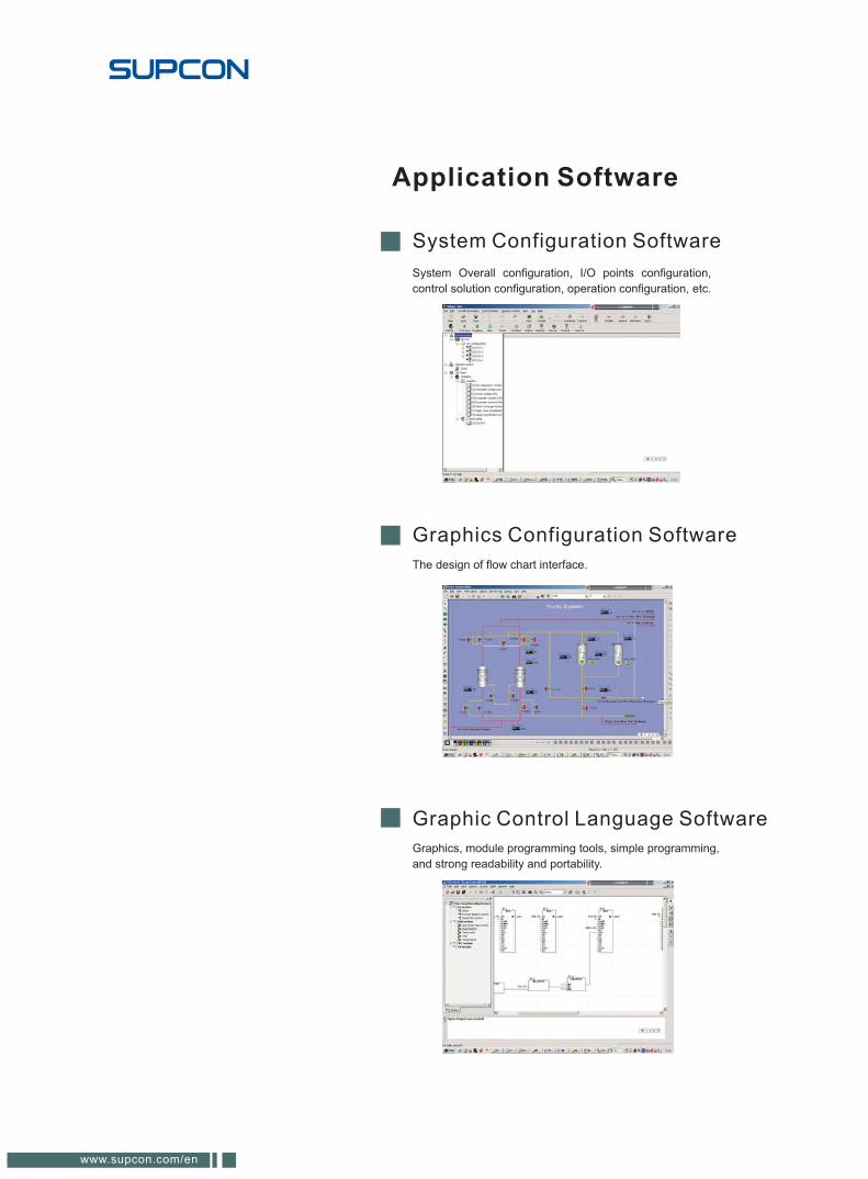
System Configuration Software
System Overall configuration, I/O points configuration,
control solution configuration, operation configuration, etc.
Graphics Configuration Software
The design of flow chart interface.
Graphic Control Language Software
Graphics, module programming tools, simple programming,
and strong readability and portability.
Application Software
www.supcon.com/en
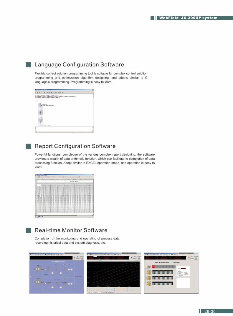
Language Configuration Software
Flexible control solution programming tool is suitable for complex control solution
programming and optimization algorithm designing, and adopts similar to C
language’s programming. Programming is easy to learn.
Report Configuration Software
Powerful functions, completion of the various complex report designing, the software
provides a wealth of data arithmetic function, which can facilitate to completion of data
processing function. Adopt similar to EXCEL operation mode, and operation is easy to
learn.
Real-time Monitor Software
Completion of the monitoring and operating of process data,
recording historical data and system diagnosis, etc.
WebField JX-300XP system
29-30
Copyright @2008,SUPCON GROUP CO,LTD.
ALL rights reserved
Reference in publication may be changed without notice
SUPCON X 0210 E 0102
Add:SUPCON Park,No.309,Liuhe Road,Binjiang District,
Hangzhou 310053,China
Tel:+86-571-86667365
Fax:+86-571-86667318
E-mail:[email protected]
http://www.supcon.com/en