wcb2 tensioner/brake with orb coolant ports - eatonpub/@eaton/@hyd/documents/content/... · eaton...
TRANSCRIPT


EATON WCB11076 WCB2 Tensioner/Brake with ORB Coolant Ports Installation, Operation and Maintenance Manual November 20142
Warning
Forward this manual to the person responsible for Installation, Operation and Maintenance of the product described herein. Without access to this information, faulty Installation, Operation or Maintenance may result in personal injury or equipment damage.
Note: Part lists in this manual are specifically for WCB2 assemblies that have cooling ports threaded to accept SAE O-ring boss type fittings. If you are maintaining a WCB2 assembly that has cooling ports threaded to accept NPT fittings, refer to manual WCB 11070 for the appropriate part lists or contact the factory for additional information.
Caution
Use Only Genuine Airflex® Replacement Parts Eaton's Airflex division recommends the use of genuine Airflex replacement parts. The use of non-genuine Airflex replacement parts could result in substandard product performance, and may void your Eaton warranty. For optimum performance, contact Airflex:
In the U.S.A. and Canada: (800) 233-5926 Outside the U.S.A. and Canada: (216) 281-2211 Internet: www.eaton.com/airflex
!!
WCB2 Tensioner/Brake with ORB Coolant PortsGeneral Information

EATON WCB11076 WCB2 Tensioner/Brake with ORB Coolant Ports Installation, Operation and Maintenance Manual November 2014 3
Table of Contents
Section Description Page No.
CUTAWAY DRAWINGS 51.0 INTRODUCTION 61.1 Description 61.2 How It Works 62.0 INSTALLATION 72.1 Preparation and Arrangements 72.2 Mounting 82.3 Air System 92.4 Coolant System 93.0 OPERATION 133.1 Conditions of Operation 133.2 Pressure and Speed Limits 133.3 Periodic Maintenance 134.0 MAINTENANCE 154.1 Wear Limits 154.2 Wear Adjustment 154.3 Disassembly Procedures 184.4 Friction Material Replacement 184.5 Wear Plate Replacement 194.6 Cylinder Seal Replacement 234.7 Bushing Replacement 244.8 Assembly Procedures 244.9 Corrosion Protection 265.0 ORDERING INFORMATION/TECHNICAL ASSISTANCE 265.1 Equipment Reference 266.0 PARTS 266.1 Parts (Standard) 266.2 Parts (Corrosion Resistant) 286.3 Parts (Breakdown of WCB2 Standard & Corrosion Resistant) 297.0 KITS 327.1 Friction Disc Kits (Standard) 327.2 Friction Disc Kits (Corrosion Resistant) 327.3 Cylinder Seal Kits 337.4 Wear Plate Kits for Mounting Flange and Pressure Plate 337.5 Wear Plate Kits for Reaction Plate 338.0 REVISION PAGE 34

EATON WCB11076 WCB2 Tensioner/Brake with ORB Coolant Ports Installation, Operation and Maintenance Manual November 20144
Index of Tables
Table No. Table Title Page No.
1 Item Description 52 Alignment Requirements 73 “A” dimension on Figure 1 - inches (mm) 74 Fastener Description and Assembly Torque - ft.-lb. (Nm) 85 Air Inlet Size 96 Coolant Pressure - psi (bar) 107 Coolant Supply Data 118 Maximum Inlet & Outlet Coolant Temperature 119 Maximum Friction Disc Assembly Speeds 1310 Wear Measurements X, Y, & Z Gaps - Inches (mm) 1711 Wear Plate Fastener Torque - ft.lb.(Nm) 2212 Inlet and Outlet Water Port Sizes 2213 Wear Limits for WCB2 Components inches (mm) 25

EATON WCB11076 WCB2 Tensioner/Brake with ORB Coolant Ports Installation, Operation and Maintenance Manual November 2014 5
21
23
29
1 7 13
17
18
19
30
33
34
28
6
12
105
'A'
Figure 1
WCB2 Tensioner/Brake with ORB Coolant Ports
Table 1 Item DescriptionItem Description
1 Mounting Flange S/A6 Stud7 Friction Disc S/A12 Clamp Tube13 Pressure Plate S/A17 Flat Washer
Item Description
18 Self Locking Nut19 Cylinder21 Seal (Inner)23 Seal (Outer)28 Gear (Not Included in P/L)29 Wear Spacer
Item Description
30 Reaction Plate S/A33 Piston34 Release Spring105 Pipe Plug
EATON WCB11076 WCB2 Tensioner/Brake with ORB Coolant Ports Installation, Operation and Maintenance Manual November 20146
1.0 INTRODUCTION
Throughout this manual there are a number of HAZARD WARNINGS that must be read and adhered to in order to prevent possible personal injury and/or damage to the equipment. Three signal words "DANGER", "WARNING", and "CAUTION" are used to indicate the severity of the hazard, and are preceded by the safety alert symbol .
Danger Denotes the most serious injury hazard, and is used when serious injury or death WILL result from misuse or failure to follow specific instructions.
Warning Used when serious injury or death MAY result from misuse or failure to follow specific instructions.
Caution Used when injury or product/equipment damage may result from misuse or failure to follow specific instructions.
It is the responsibility and the duty of all personnel involved in the installation, operation and maintenance of the equipment on which this device is used to fully understand the procedures by which hazards are to be avoided.
Danger Warning Caution
1.1 Description
1.1.1 The Airflex® WCB2 water-cooled tensioner/brake assembly is designed for constant tension applications. It is exceptionally well suited for high inertia stopping and rapid heat dissipation. The design of the WCB2 water-cooled tensioner/brake assembly permits mid-shaft or end-shaft mounting. The rugged construction ensures long, trouble free service.
1.1.2 WCB2 water-cooled tensioner/brake assemblies are available in various sizes and quantities of friction discs assemblies. The model number identifies the number of friction disc assemblies and the nominal disc diameter. For example, 324WCB2 indicates three 24" diameter discs.
1.1.3 When size, such as 36WCB2, is referred to in this manual, it means that the information given applies to all models using the 36" diameter water-cooled disc assembly; i.e., 236WCB2, 336WCB2, etc.
1.1.4 All WCB2 tensioner/brake assemblies referred to in this IOM have SAE O-ring Boss (ORB) ports for the coolant inlets and outlets. These ports utilize a straight thread and an O-ring for sealing versus the NPT tapered thread used previously and referred to in IOM WCB 11070. The ORB ports provide superior sealing properties and reduce the risk of damage to the brake during fitting installation.
1.1.5 WCB2 tensioner/brake assemblies can be used with either closed loop or open loop water systems.
1.1.6 This manual includes metric equivalents usually shown in brackets (#) following the U.S. measurement system value. Be sure to use the correct value.
1.2 How It Works
1.2.1 Referring to Figure 1, the gear (28) is mounted on the shaft which is to be stopped and the WCB2 tensioner/brake assembly assembly is attached to the machine frame or a reaction bracket.
Air pressure is applied through the ports in the cylinder (19) causing the piston (33) and pressure plate assembly (13) to move towards the mounting flange, compressing the release springs. As the applied pressure increases, the friction disc(s) are clamped between the pressure plate and mounting flange, stopping or controlling the shaft the discs are mounted on. Modulation of air pressure then controls applied torque of the WCB2 tensioner/brake assembly. Multiple disc brakes utilize reaction plates (30) between the friction disc assemblies. The release springs (34) assist in disengagement and retraction of the piston, pressure plate, and reaction plates, if applicable. High heat dissipation is accomplished by passing water through a special cavity behind the copper alloy wear plates.
Torque flows through the WCB2 tensioner/brake assembly from the shaft to be controlled, through the friction disc assemblies, through the pressure plate and reaction plates, through the clamp tubes and studs, to the mounting flange, which is attached to a rigid surface.
WCB2 Tensioner/Brake with ORB Coolant Ports
EATON WCB11076 WCB2 Tensioner/Brake with ORB Coolant Ports Installation, Operation and Maintenance Manual November 2014 7
2.0 INSTALLATION
Warning Only qualified maintenance personnel should install, adjust or repair these units. Faulty workmanship will result in unreasonable exposure to hazardous conditions or personal injury.
Caution Read these instructions thoroughly and review until you fully understand the installation sequence before proceeding with the work described in this section. Failure to follow these instructions will result in unreasonable exposure to hazardous conditions or personal injury.
Caution Do not paint the clamp tubes (12), wear spacers (29), or the release springs (34), as this may hinder the engagement or disengagement of the WCB2 tensioner/brake assembly.
Note: Some three and four disc units may require support on the cylinder end of the WCB2 tensioner/brake assembly in certain high torque applications. Contact the factory for specific application information.
2.1 Preparation and Arrangements
2.1.1 Refer to the appropriate catalog information (available upon request) for appropriate envelope dimensions, mounting register diameters, mounting bolt circles and positions, and stud support bracket recommendations for each specific WCB2 tensioner/brake assembly.
2.1.2 The WCB2 tensioner/brake assembly's reaction member (such as the machine frame) should have a machined register to allow for mounting and alignment control of the WCB2 tensioner/brake assembly. The mounting surface should be designed to provide full support of the face of the mounting flange (1), preventing deflection during operation.
2.1.3 For proper operation and service life, the WCB2 tensioner/brake assembly's reaction member must be aligned to the shaft within the limits shown in Table 2.
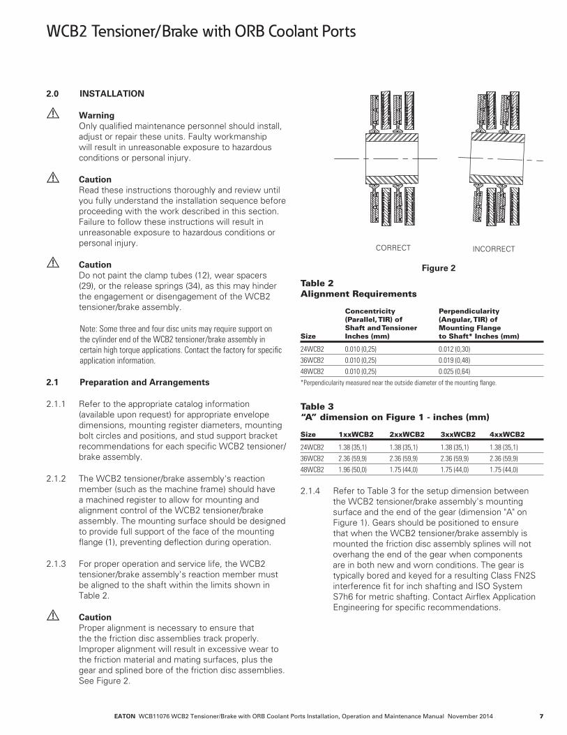
Caution Proper alignment is necessary to ensure that the the friction disc assemblies track properly. Improper alignment will result in excessive wear to the friction material and mating surfaces, plus the gear and splined bore of the friction disc assemblies. See Figure 2.
CORRECT INCORRECT
Figure 2
Table 2 Alignment Requirements Concentricity Perpendicularity (Parallel, TIR) of (Angular, TIR) of Shaft and Tensioner Mounting Flange Size Inches (mm) to Shaft* Inches (mm)
24WCB2 0.010 (0,25) 0.012 (0,30)36WCB2 0.010 (0,25) 0.019 (0,48)48WCB2 0.010 (0,25) 0.025 (0,64)*Perpendicularity measured near the outside diameter of the mounting flange.
Table 3 “A” dimension on Figure 1 - inches (mm) Size 1xxWCB2 2xxWCB2 3xxWCB2 4xxWCB2
24WCB2 1.38 (35,1) 1.38 (35,1) 1.38 (35,1) 1.38 (35,1)36WCB2 2.36 (59,9) 2.36 (59,9) 2.36 (59,9) 2.36 (59,9)48WCB2 1.96 (50,0) 1.75 (44,0) 1.75 (44,0) 1.75 (44,0)
2.1.4 Refer to Table 3 for the setup dimension between the WCB2 tensioner/brake assembly's mounting surface and the end of the gear (dimension "A" on Figure 1). Gears should be positioned to ensure that when the WCB2 tensioner/brake assembly is mounted the friction disc assembly splines will not overhang the end of the gear when components are in both new and worn conditions. The gear is typically bored and keyed for a resulting Class FN2S interference fit for inch shafting and ISO System S7h6 for metric shafting. Contact Airflex Application Engineering for specific recommendations.
WCB2 Tensioner/Brake with ORB Coolant Ports

EATON WCB11076 WCB2 Tensioner/Brake with ORB Coolant Ports Installation, Operation and Maintenance Manual November 20148
2.2 Mounting
2.2.1 The WCB2 must be mounted to a clean, rigid surface 2with hardened flat washers and screws of the grade, quantity, and size as listed in Table 4. Mounting to a properly aligned, rigid surface that fully supports the face of the mounting flange minimizes any deflection during operation and helps to ensure that the the friction disc assemblies will track properly on the copper wear plates.
Note: To facilitate the mounting process, the friction disc assemblies should be aligned to the gear and centered in the WCB2 tensioner/brake assembly. With the WCB2 tensioner/brake assembly positioned with the mounting flange facing down, lower the gear (28) slowly and carefully into the splined bore of the friction disc assemblies (7). Adjust the discs so that they are centered in the WCB2 tensioner/brake assembly and fit in the gear. Apply and maintain an air pressure of 25 psig (1.7 bar) to the cylinder. This will engage and hold the friction disc assemblies in position during installation. Remove the gear.
Danger Use only the proper number and grade fasteners shown in Table 4. Use of commercial grade (Grade 2) fasteners where Grade 8 fasteners are specified may result in failure of the fasteners and a sudden and drastic reduction in brake torque.
Caution Water inlets and outlets must be located as close as possible to the 6 o'clock and 12 o'clock positions, respectively. This will help to prevent air pockets in the water cavities, which would allow the WCB2 tensioner/brake assembly to overheat.
2.2.2 Ensure that the shaft is free of nicks or burrs and the key fits properly in the shaft and gear.
2.2.3 Apply a light coat of anti-seizing compound to the shaft and key. Tap the key into the shaft keyway.
2.2.4 Heat the gear uniformly to 250oF (121oC) to expand the bore and ease assembly. Press the gear onto the shaft, making sure that the dimension between the gear and the WCB2 tensioner/brake assembly's mounting surface ("A") is maintained. See Figure 1 and Table 3. Allow the gear to cool.
2.2.5 Apply a thin coat of MOLUB-ALLOY® 936 SF Heavy or equivalent grease to the splines of the gear.
Caution Excessive lubricant may contaminate friction material, resulting in erratic response or loss of torque.
Caution The use of anti-seize or bearing greases on the gear splines may result in premature gear and friction disc assembly spline wear.
2.2.6 Pre-fill the grease channel in the friction disc assembly splines (if applicable) with MOLUB-ALLOY® 936 SF Heavy or equivalent grease, as shown on Figure 3.
CHANNEL IS FILLED WITH MOLUB-ALLOY 936 SF HEAVY GREASE
.12" (3.0 mm)
Figure 3
2.2.7 Rig the WCB2 into position and slide it over the gear. Avoid placing lifting straps or cables directly on the release springs (34).
Table 4 Fastener Description and Assembly Torque - ft.-lb. (Nm) Item Description Specification 24WCB2 36WCB2 48 WCB2
4 Wear Plate Screw Size 5/16-18 NC Gr. 8 3/8-16-NC2 Gr. 8 3/8-16-NC2 Gr. 8 5 Locknut Quantity 90 108 120 Torque, Dry 21 (28) 40 (54) 40 (54)18 Locknut Size 1 1/8-7 NC Gr. 8 1 3/8-6 NC Gr. 8 1 3/8-6 NC Gr. 8 Quantity 12 16 16 Torque, Lubed 500 (677) 750 (1016) 750 (1016)Customer Mounting Screw Size 5/8-11NC-2 Gr. 8 1-8 NC Gr. 8 1 3/8-6NC Gr. 5 Supplied Quantity 10 14 14 Torque, Lubed 150 (203) 660 (895) 1100 (1490)Customer SAE Coolant Fittings Size SAE-12 SAE-20 SAE-20 Supplied Quantity* 4 4 4 Torque, O-Ring Lube 68-78 (92-105) 146-171 (198-231) 146-171 (198-231)*Note: Increase the quanity of SAE coolant fittings by 4 for each Reaction Plate S/A (30) in the WCB2 tensioner/brake assembly.
WCB2 Tensioner/Brake with ORB Coolant Ports

EATON WCB11076 WCB2 Tensioner/Brake with ORB Coolant Ports Installation, Operation and Maintenance Manual November 2014 9
2.2.8 Attach the mounting flange (1) to the mounting surface using the appropriate fasteners. If applied pressure was used to help position the discs during mounting, exhaust the air pressure prior to tightening the fasteners. Tighten the fasteners to the specified torque value. See Table 4.
Caution Maximum allowable air pressure in the cylinder (19) is 150 psig (10.2 bar).
2.2.9 WCB2 tensioner/brake assemblies should be covered to protect the unit from dirt, rain, overspray, and other sources of external contamination. In extreme environments the use of a sealed enclosure with internal strip heater is recommended to prevent moisture from collecting on the unit.
2.3 Air System
Warning Maximum allowable air pressure is 150 psig (10.2 bar). Application of pressure exceeding maximum allowable may result in damage to the WCB2 tensioner/brake assembly.
2.3.1 Maximum allowable pressure is 150 psig (10.2 bar).
2.3.2 Use only clean, filtered air (a 50 micron filter or better is recommended) which is free of excess moisture.
2.3.3 Air inlet sizes are shown in Table 5. Air inlets are located on the face of the cylinder (19). For cylinders with three ports, the lowest port should be located at or near the 6 o'clock position to facilitate purging of moisture that may accumulate in the air system or cylinder.
Note: Positioning the drain plug (105) at a nominal 6 o’clock position will help insure the coolant inlets and outlets are at a nominal 12 o’clock and 6 o’clock position.
Table 5 Air Inlet Size Size Thread Size
24WCB2 1/2"-14 NPT36WCB2 3/4"-14 NPT48WCB2 1"-11.5 NPT
2.3.4 All pipes should be free of metal chips, cutting compound and any other foreign matter. Pipe ends should be reamed after cutting to eliminate possible restrictions. For optimum air system response, a minimum number of bends and elbows should be used.
2.3.5 The WCB2 tensioner/brake assembly does not require lubricated air; however associated control valves may. Consult the valve manufacturer for appropriate recommendations.
2.4 Coolant System
2.4.1 An ORB port can be identified by the machined spot face and a chamfer (for sealing of the O-ring). See Figure 4. See Table 4 for the torque values and the SAE fitting size associated with each WCB2 tensioner/brake assembly.
ORB PORTFigure 4
Caution Make sure that the water inlets and outlets are positioned as close as possible to the 6 o'clock and 12 o'clock positions, respectively. This will help to minimize the formation of air pockets in the water cavity during operation, which could contribute to overheating of the WCB2 tensioner/brake assembly.
Caution Installation of NPT or other incompatible threaded piping or fittings into ORB ports will damage the ports, resulting in leakage or other failure.
2.4.2 Installation of straight SAE fittings.
2.4.2.1 Inspect the SAE fittings for damage and contamination.
2.4.2.2 Apply Molykote® 55 O- ring lubricant to the O- ring on the SAE fitting.
2.4.2.3 Turn the SAE fitting into ORB port until finger tight, then apply the respective assembly torque. Refer to Table 4.
2.4.3 Installation of adjustable SAE fittings.
WCB2 Tensioner/Brake with ORB Coolant Ports
EATON WCB11076 WCB2 Tensioner/Brake with ORB Coolant Ports Installation, Operation and Maintenance Manual November 201410
2.4.3.1 Inspect the SAE fittings for damage and contamination.
2.4.3.2 Apply Molykote® 55 O- ring lubricant to the O- ring on the SAE fitting.
2.4.3.3 Ensure the O-ring and back up washer on the SAE fitting are in the proper position on non-threaded section of the SAE fitting nearest to locknut.
2.4.3.4 Tighten the SAE fitting by hand into the threads of the ORB port until the back-up washer contacts the face of the ORB port.
2.4.3.5 To position the SAE fitting, unscrew the SAE fitting up to one full turn then hold the SAE fitting in desired position and tighten locknut so that the back-up washer contacts face of ORB port and forces the O-ring on the SAE fitting within the boss cavity. Tighten to the torque listed in Table 4.
Caution When installing SAE fittings male NPT fittings are very similar in size to SAE threads and will engage in the female SAE threaded ports. If this is done the WCB2 tensioner/brake assembly may be damaged! Only use SAE fittings in the coolant ports of the WCB2 tensioner/brake assembies.
2.4.4 Maximum allowable coolant pressure within the water cavity is water cavity is 40 psig (2.7 bar) for 36WCB2 and 48WCB2 tensioner/brake assemblies and water cavity is 45 psig (3.1 bar) 24WCB2 tensioner/brake assemblies. See Table 6 for coolant pressure limitations as measured at the inlets and outlets of water jackets. Note that inlet pressures exceeding the maximum allowable static pressures are only permissible under dynamic flow conditions, provided that the average pressure between the inlet and outlet does not exceed the maximum allowable pressure stated above. The use of an accumulator or pressure relief valve may be desirable to reduce the effect of pressure spikes in the coolant system during operation.
Caution High outlet pressures or surges exceeding maximum allowable may result in damage to the WCB2 tensioner/brake assembly.
Caution Maximum allowable water pressure is dependent upon WCB2 tensioner/brake assembly size and specific application requirements.
Caution Inlet pressures exceeding the maximum allowable average pressure are only permissible when the outlet pressures are at or below the limits listed in Table 6.
Table 6 Coolant Pressure - psi (bar) Maximum Maximum Maximum Static Inlet Average Size Pressure Pressure* Pressure1*
24WCB2 45 (3,1) 65 (4,5) 45 (3,1)36WCB2 40 (2,7) 60 (4,1) 40 (2,7)48WCB2 40 (2,7) 60 (4,1) 40 (2,7)1 Maximum Average Pressure = (Inlet + Outlet)/2 *Under Dynamic Flow Conditions Note: Minimum outlet pressure under dynamic flow conditions equals zero. Note: Above ratings for tensioning / winding type applications. For high cyclic applications, consult the factory.
2.4.5 The coolant supply and discharge hose, pipe and fitting sizes, along with minimum flow rates for the WCB2 tensioner/brake assembly's rated horsepower, are listed in Table 7.
2.4.6 Coolant supply connections to the WCB2 tensioner/brake assembly should provide a parallel flow through each section of the tensioner. Series flow is not recommended, as it can lead to overheating of the WCB2 tensioner/brake assembly.
2.4.7 Inlet and outlet coolant manifolds must be provided. Manifolds should be constructed to allow for even flow through all ports. Two hoses can be routed to the reaction plates (30) to assist with balancing the flow to each wear plate.
2.4.8 Use flexible connecting hose to each WCB2 tensioner/brake assembly's coolant section to allow axial travel of the pressure plate, reaction plate, and end plate during the WCB2 tensioner/brake assembly's operation without restricting the movement of components. When determining hose lengths, consideration should be given to movement and location of the pressure plate and reaction plate as friction material wears. Hose lengths running between the manifolds and the inlet or outlet ports should be equal in length, if possible. Reductions in the recommended line diameter should be avoided to prevent excessive line pressures.
WCB2 Tensioner/Brake with ORB Coolant Ports

EATON WCB11076 WCB2 Tensioner/Brake with ORB Coolant Ports Installation, Operation and Maintenance Manual November 2014 11
Table 7 Coolant Supply Data Min. Flow Min. Flow Min. Flow Water Inlet Rate GPM Rate GPM Rate GPM and Outlet Min. Flow (dm³/min) (dm³/min) (dm³/min) Thermal Pipe Size Rate GPM 70% Water, 60% Water, 50% Water, Rating (Minimum (dm³/min) 30% Ethylene 40% Ethylene 50% Ethylene Model HP (kW)1 piping I.D.) 100% Water2 Glycol by vol.3 Glycol by vol.4 Glycol by vol.5
124 270 (201) SAE-12 27 (102) 32 (121) 35 (132) 40 (151) 224 540 (402) (3/4") 54 (204) 64 (242) 70 (265) 80 (303) 324 810 (603) 81 (305) 96 (361) 105 (395) 120 (451) 424 1080 (805) 108 (406) 128 (481) 140 (526) 160 (602)136 650 (485) SAE-20 65 (246) 76 (288) 84 (318) 98 (371) 236 1300 (969) (1") 130 (489) 152 (572) 168 (632) 196 (737) 336 1950 (1454) 195 (738) 228 (863) 253 (958) 294 (1113) 436 2600 (1937) 260 (978) 304 (1143) 336 (1263) 392 (1474)148 1300 (969) SAE-20 130 (489) 152 (572) 168 (632) 196 (737) 248 2600 (1937) (1-1/4") 260 (978) 304 (1143) 336 (1263) 392 (1474) 348 3900 (2906) 390 (1467) 456 (1715) 504 (1895) 588 (2211) 448 5200 (3874) 520 (1956) 608 (2286) 672 (2526) 784 (2948)1. Thermal rating based on a 70°F (21°C) water inlet temperature and a 50°F (28°C) temperature rise between inlet and outlet. 2. 10HP/GPM, (1.97kw/(dm³/min)) 3. 8.55HP/GPM, (1.68kw/(dm³/min)) 4. 7.74HP/GPM, (1.53kw/(dm³/min)) 5. 6.63HP/GPM, (1.31kw/(dm³/min)) Note: Minimum Flow Rates listed above are to achieve thermal rating. Lower flow rates are acceptable provided that they satisfy peak thermal requirement
2.4.9 Avoid the use of sharp bends and elbows that will restrict water flow. Loops and bends in the lines may create air pockets, which substantially reduce the flow of coolant and can contribute to overheating.
2.4.10 Coolant and coolant supply lines should be free of foreign material (a 500 micron water filter is recommended). In the event that contaminated water is used as a coolant (not generally recommended), use of a multi-stage filter/strainer may be desirable to avoid the need for frequent cleaning of fine mesh filters.
2.4.11 Figure 5 illustrates a typical closed loop liquid to liquid coolant system. The heat exchanger and temperature control would be replaced with a radiator, fan and motor in a liquid to air system.
2.4.12 The coolant supply temperature at the inlet should be 100oF (38oC) or lower. The coolant outlet temperature should not exceed the values given in Table 8. However, in no event should there be more than a 50oF (28oC) temperature rise between inlet and outlet. See Table 8 for maximum allowable outlet coolant temperature with various water/ethylene glycol mixtures and other cooling media.
Table 8 Maximum Inlet & Outlet Coolant Temperature Water/ Maximum Maximum Maximum Ethylene Allowable Allowable Allowable Glycol Coolant Inlet Coolant Outlet Coolant Mixture Temperature Temperature Temperature °F (°C)* °F (°C) Rise°F (°C)
100/0 100 (38) 150 (66) 50 (28)70/30 115 (46) 165 (74) 50 (28)60/40 115 (46) 165 (74) 50 (28)50/50 120 (49) 170 (77) 50 (28)* Provided that temperature rise is no greater than 50°F (28°C)
WCB2 Tensioner/Brake with ORB Coolant Ports

EATON WCB11076 WCB2 Tensioner/Brake with ORB Coolant Ports Installation, Operation and Maintenance Manual November 201412
)( )( )( )( )(
)( )(
)( )( )(
)( )( )( )(
OUTLET MANIFOLD
OUTLET MANIFOLD
OUTLET MANIFOLD
OUTLET MANIFOLD
SINGLE
DUAL
TRIPLE
QUAD
16% 34% 34% 16%
12.5% 25% 25% 25%12.5%
50% 50%
25% 50% 25%
PRESSURE SWITCH
PRESSURE RELIEF VALVE
MOTOR
STRAINER
TEMPERATURE SWITCH
Figure 5
2.4.13 Open Loop Systems
For efficient operation of the WCB2 tensioner/brake assembly, an adequate supply of filtered fresh water is required. (See 2.4.4 - 2.4.5). Excessive water hardness promotes the formation of scale deposits, which, in time, will affect the service life of the WCB2 tensioner/brake assembly.
Water of high acidity or high in corrosive salts may cause electrolytic corrosion between the dissimilar metals used in the water cavities. Water treatment should be considered if the properties of the water exceed the following:
Equivalent calcium carbonate content hardness: Maximum 100 p.p.m. pH value: 7.0 to 9.0.
Caution Open loop systems should be thoroughly flushed with clean fresh water after operation to reduce the corrosive effects of contaminants on internal components.
2.4.14 Closed Loop Systems
For efficient operation of the WCB2 tensioner/brake assembly in a closed loop system, ethylene glycol coolant conforming to SAE Standard J1034 should be used. For preparation of the proper concentration of a water/ethylene glycol mixture, use make-up water which is low in corrosive ions such as chlorides and sulfates.
Recommended pH value of the water/ethylene glycol mixture: 7.5. to 10.5.
WCB2 Tensioner/Brake with ORB Coolant Ports

EATON WCB11076 WCB2 Tensioner/Brake with ORB Coolant Ports Installation, Operation and Maintenance Manual November 2014 13
3.0 OPERATION
3.1 Conditions of Operation
The following Hazard Warnings are to be followed for proper WCB2 tensioner/brake assembly's functioning:
Warning Friction material must be worn-in to achieve product torque rating. For new installations or after repair, a minimum wear-in period for the friction couple of four hours at 50% of the rated horse-power is recommended to achieve rated torque. Verify proper operation before putting the product into service.
Warning Protective means must be used to prevent oil, grease, dirt or coolant from coming into contact with the surfaces of the friction discs (8), or the wear plates (3). Oil or grease on these parts will significantly reduce the torque capacity of the unit. Dirt or coolant will produce erratic torque. Do not risk personal injury or damage to the equipment.
Warning Maximum free-wheeling speed must not exceed the speeds listed in Table 9. Exposure to speeds in excess of these values may cause the friction discs (8) to burst and result in extensive damage to the the WCB2 tensioner/brake assembly and/or cause personal injury.
Caution For proper cooling of the WCB2 tensioner/brake assembly, it is required that the coolant inlet be located as close as possible to the 6 o'clock position and the outlet be located near the 12 o'clock position. This will help to assure that all coolant cavities are water filled to help avoid overheating.
Caution For operation in subfreezing temperatures, ethylene glycol antifreeze must be added to the water. The antifreeze content of the mixture is critical and should not exceed 50% by volume. Excessive amounts of antifreeze will reduce cooling capacity and can cause coolant leakage due to overheating. Refer to Table 8.
Caution Maximum ambient temperature is 110oF (43oC). Minimum ambient temperature for closed loop systems using ethylene glycol antifreeze is 0oF (-18oC). For open loop systems using water as a coolant, the minimum ambient temperature is 45oF (7oC).
Table 9 Maximum Friction Disc Assembly Speeds Max. Slip Max. Free Wheeling Size Speed RPM Speed RPM
24WCB2 715 120036WCB2 475 70048WCB2 360 600
3.2 Pressure and Speed Limits
3.2.1 Maximum applied air pressure is 150 psig (10.2 bar).
3.2.2 Maximum coolant pressure allowable within the water cavities is 40 psig (2,7 bar) for for the 36WCB2 and 48WCB2 tensioner/brake assemblies and 45 psig (3,1 bar) for the 24WCB2 tensioner/brake assemblies. The use of an accumulator or pressure relief valve may be desirable to reduce the effect of pressure spikes in the coolant system during operation.
Warning Maximum allowable water pressure is dependent upon the WCB2 tensioner/brake assemblies model type. Water piping elevations, restrictions in outlet piping or pressure surges may cause pressures that exceed the maximum allowable, resulting in damage to the WCB2 tensioner/brake assembly.
3.2.3 Maximum slip speeds and free-wheeling friction disc assembly speeds are shown in Table 9.
Caution Excessive slip speeds will result in rapid friction material wear. For good life of wear components, the operating values in Table 9 should not be exceeded.
3.3 Periodic Maintenance
3.3.1 As the friction material wears, adjustment of the WCB2 tensioner/brake assembly may be required to keep pistons within the proper stroke range. See Section 4.1 - 4.2 and Table 13 for wear measurements, adjustment procedures and component wear indication.
3.3.2 Periodically check for external air leakage in the area of the piston seals (21) (23). For replacement, refer to procedures in Section 4.6.
3.3.3 Moisture that may accumulate in the cylinder can be purged. With air pressure exhausted from the cylinder, remove the pipe plug (105) at the 6 o'clock position on the cylinder, and apply low air pressure to assist in expelling any excess moisture. After draining the cylinder, reinstall the pipe plug, applying a pipe thread sealant on the threads prior to installation.
WCB2 Tensioner/Brake with ORB Coolant Ports

EATON WCB11076 WCB2 Tensioner/Brake with ORB Coolant Ports Installation, Operation and Maintenance Manual November 201414
Caution Applied air pressure greater than 10 psig (0.69 bar) should not be used when draining the cylinder. Use adequate shielding to avoid contact with direct spray from moisture being purged from the cylinder.
3.3.4 Periodically observe the rotating friction disc assemblies while the WCB2 tensioner/brake assembly is fully released. Dragging discs may be caused by wear or contamination of the gear or friction disc assemblies splines, lack of spline lubrication, friction disc assemblies imbalance, warped friction disc assemblies, or misalignment. Correct as required.
3.3.5 Pneumatic and electrical control interlocks should be periodically checked for proper settings and operation.
3.3.6 If leakage or blockage of any water-cooled chamber is suspected, a static or dynamic test may be performed as follows:
3.3.6.1 Static Pressure Test:
(a) Release the WCB2 tensioner/brake assembly by exhausting the air pressure from the WCB2 tensioner/brake assembly and secure the air supply during this test.
Warning Ensure that the machinery will remain in a safe position prior to releasing the WCB2 tensioner/brake assembly.
(b) Bleed all air from within the coolant cavity. Air bleeding must be accomplished by running coolant through the cavity with the WCB2 tensioner/brake assembly secured in its proper operating position.
Note: Avoid contaminating the friction material with coolant or water.
Warning Contamination of the friction material could result in erratic or loss of torque.
(c) After the air has been removed, install a pipe plug(s) in the outlet(s) and apply maximum allowable coolant pressure measured at the inlet to the water cavity. Maximum allowable is 40 psig (2.7 bar) for the 36WCB2 and 48WCB2 tensioner/brake assemblies, and 45 psig (3.0 bar) for the 24WCB2 tensioner/brake assemblies. Maintain this pressure for 30 minutes. Check for leakage at O.D. and I.D. sealing areas.
Caution Be sure that air pressure is exhausted from the cylinder (19) of the tensioner to release the spring pressure on the tensioner/brake during static coolant pressure testing. Engagement of the brake during testing could develop surge pressures exceeding the maximum allowable within the coolant cavities resulting in possible damage to the seals.
3.3.6.2 Dynamic Flow Test:
(a) Dynamic flow testing of the WCB2 tensioner/brake assembly should be conducted at the required flow rate for the rated HP dissipation and coolant quality, as given in Table 7. Inlet and outlet pressures for the appropriate WCB2 tensioner/brake assembly model as listed in Table 6 should not to be exceeded.
(b) There should be no restrictions on the outlet side of the WCB2 tensioner/brake assembly to cause any back pressure to the unit. Coolant inlet and outlet sizes are listed in Table 7. Full size hoses and piping should be used. Check for low flow and/or leakage at the O.D. and I.D. seal areas.
WCB2 Tensioner/Brake with ORB Coolant Ports
EATON WCB11076 WCB2 Tensioner/Brake with ORB Coolant Ports Installation, Operation and Maintenance Manual November 2014 15
4.0 MAINTENANCE
Warning Before performing any maintenance work on the WCB2 tensioner/brake assembly, make sure that the machinery will remain in a safe position. Failure to do so could result in serious injury or possibly death.
Warning Only qualified maintenance personnel should install, adjust or repair the WCB2 tensioner/brake assembly. Faulty workmanship will result in unreasonable exposure to hazardous conditions or personal injury.
Caution Read these instructions thoroughly and review until you fully understand the parts replacement steps before proceeding with the work described in this section. Failure to follow these instructions can result in unreasonable exposure to hazardous conditions or personal injury.
4.1 Wear Limits
Warning Periodically examine the WCB2 tensioner/brake assembly for wear of friction material and wear plates. Failure to perform this examination periodically may result in excessive wear to components, improper operation or a significant reduction in torque, and may result in personal injury and/or damage to the machinery.
4.1.1 Wear limits for the WCB2 tensioner/brake assembly's components are shown in Table 13. If any wear limit has been reached or exceeded, that component must be repaired or replaced.
4.2 Wear Adjustment
Warning If a wear adjustment is not made when required, the brake torque may deteriorate to the point where the equipment will not stop properly.
4.2.1 Determining Wear
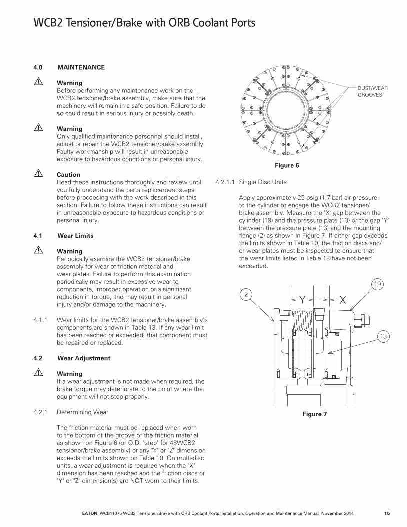
The friction material must be replaced when worn to the bottom of the groove of the friction material as shown on Figure 6 (or O.D. "step" for 48WCB2 tensioner/brake assembly) or any "Y" or "Z" dimension exceeds the limits shown on Table 10. On multi-disc units, a wear adjustment is required when the "X" dimension has been reached and the friction discs or "Y" or "Z" dimension(s) are NOT worn to their limits.
DUST/WEARGROOVES
Figure 6
4.2.1.1 Single Disc Units
Apply approximately 25 psig (1.7 bar) air pressure to the cylinder to engage the WCB2 tensioner/brake assembly. Measure the "X" gap between the cylinder (19) and the pressure plate (13) or the gap "Y" between the pressure plate (13) and the mounting flange (2) as shown in Figure 7. If either gap exceeds the limits shown in Table 10, the friction discs and/or wear plates must be inspected to ensure that the wear limits listed in Table 13 have not been exceeded.
2
19
13
Y X
Figure 7
WCB2 Tensioner/Brake with ORB Coolant Ports

EATON WCB11076 WCB2 Tensioner/Brake with ORB Coolant Ports Installation, Operation and Maintenance Manual November 201416
4.2.1.2 Multi - Disc Units
Apply approximately 25 psig (1.7 bar) air pressure to the cylinder to engage the tensioner. Measure the gap "X" between the cylinder (19) and the pressure plate (13) to determine if adjustment may be required.
Measure the "Y" gap between the pressure plate (13) and the reaction plate (31), the "Y" gap between the reaction plate (31) and the mounting flange (2), and the "Z" gap between the reaction plates (31) as shown in Figures 8, 9, 10.
If the "X worn" dimension has been reached or exceeded and the "Y" or "Z" dimensions have not reached the limits shown in Table 10 and none of the friction discs are worn to the bottom of the wear groove / step, wear adjustment is required. It is also recommended that wear plates be inspected to ensure that the wear limits listed in Table 13 have not been exceeded.
Warning If wear adjustment is not made, the piston may extend out of the cylinder beyond an acceptable operating range, resulting in loss of torque and/or seal damage.
If the "Y" or "Z" dimensions have been reached or any of the friction discs are worn to the bottom of the wear groove (or step), the WCB2 tensioner/brake assembly should be taken out of service and rebuilt with new components as required.
2
3119
13
Y Y X
Figure 8
2
3119
13
Y Z Y X
Figure 9
2
31
19
13
Y Z Z Y X
Figure 10
4.2.2 Adjustment Procedure
Wear adjustment can be conducted without full disassembly of the WCB2 tensioner/brake assembly. The wear adjustment spacers are slotted to allow for easy removal with a chisel.
Warning Before performing any maintenance work on the WCB2 tensioner/brake assembly, make sure that the machinery will remain in a safe position. Failure to do so could result is serious injury or possibly death.
Note: It may be necessary to disconnect air and water supply lines to prevent damage to the hoses and binding of components during the adjustment procedure.
4.2.2.1 Wear spacers should be removed in complete sets only (one from each stud location). Mark the spacers to be removed to avoid confusion during removal.
Warning Removal of spacers in quantities other than complete sets (layers) will result in severe damage to WCB2 tensioner/brake assembly components during reassembly, and could cause the WCB2 tensioner/brake assembly to not function properly.
WCB2 Tensioner/Brake with ORB Coolant Ports
EATON WCB11076 WCB2 Tensioner/Brake with ORB Coolant Ports Installation, Operation and Maintenance Manual November 2014 17
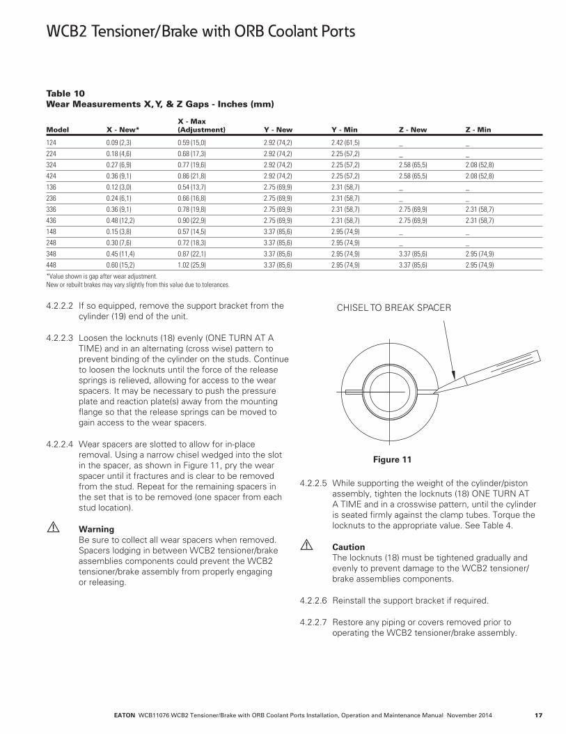
Table 10 Wear Measurements X, Y, & Z Gaps - Inches (mm) X - Max Model X - New* (Adjustment) Y - New Y - Min Z - New Z - Min
124 0.09 (2,3) 0.59 (15,0) 2.92 (74,2) 2.42 (61,5) _ _224 0.18 (4,6) 0.68 (17,3) 2.92 (74,2) 2.25 (57,2) _ _324 0.27 (6,9) 0.77 (19,6) 2.92 (74,2) 2.25 (57,2) 2.58 (65,5) 2.08 (52,8)424 0.36 (9,1) 0.86 (21,8) 2.92 (74,2) 2.25 (57,2) 2.58 (65,5) 2.08 (52,8)136 0.12 (3,0) 0.54 (13,7) 2.75 (69,9) 2.31 (58,7) _ _236 0.24 (6,1) 0.66 (16,8) 2.75 (69,9) 2.31 (58,7) _ _336 0.36 (9,1) 0.78 (19,8) 2.75 (69,9) 2.31 (58,7) 2.75 (69,9) 2.31 (58,7)436 0.48 (12,2) 0.90 (22,9) 2.75 (69,9) 2.31 (58,7) 2.75 (69,9) 2.31 (58,7)148 0.15 (3,8) 0.57 (14,5) 3.37 (85,6) 2.95 (74,9) _ _248 0.30 (7,6) 0.72 (18,3) 3.37 (85,6) 2.95 (74,9) _ _348 0.45 (11,4) 0.87 (22,1) 3.37 (85,6) 2.95 (74,9) 3.37 (85,6) 2.95 (74,9)448 0.60 (15,2) 1.02 (25,9) 3.37 (85,6) 2.95 (74,9) 3.37 (85,6) 2.95 (74,9)*Value shown is gap after wear adjustment. New or rebuilt brakes may vary slightly from this value due to tolerances.
4.2.2.2 If so equipped, remove the support bracket from the cylinder (19) end of the unit.
4.2.2.3 Loosen the locknuts (18) evenly (ONE TURN AT A TIME) and in an alternating (cross wise) pattern to prevent binding of the cylinder on the studs. Continue to loosen the locknuts until the force of the release springs is relieved, allowing for access to the wear spacers. It may be necessary to push the pressure plate and reaction plate(s) away from the mounting flange so that the release springs can be moved to gain access to the wear spacers.
4.2.2.4 Wear spacers are slotted to allow for in-place removal. Using a narrow chisel wedged into the slot in the spacer, as shown in Figure 11, pry the wear spacer until it fractures and is clear to be removed from the stud. Repeat for the remaining spacers in the set that is to be removed (one spacer from each stud location).
Warning Be sure to collect all wear spacers when removed. Spacers lodging in between WCB2 tensioner/brake assemblies components could prevent the WCB2 tensioner/brake assembly from properly engaging or releasing.
CHISEL TO BREAK SPACER
Figure 11
4.2.2.5 While supporting the weight of the cylinder/piston assembly, tighten the locknuts (18) ONE TURN AT A TIME and in a crosswise pattern, until the cylinder is seated firmly against the clamp tubes. Torque the locknuts to the appropriate value. See Table 4.
Caution The locknuts (18) must be tightened gradually and evenly to prevent damage to the WCB2 tensioner/brake assemblies components.
4.2.2.6 Reinstall the support bracket if required.
4.2.2.7 Restore any piping or covers removed prior to operating the WCB2 tensioner/brake assembly.
WCB2 Tensioner/Brake with ORB Coolant Ports

EATON WCB11076 WCB2 Tensioner/Brake with ORB Coolant Ports Installation, Operation and Maintenance Manual November 201418
4.3 Disassembly Procedures
Warning Ensure that the machinery is and will remain in a safe position prior to loosening fasteners or removing the WCB2 tensioner/brake assembly.
4.3.1 Disconnect the air supply lines and water lines from the WCB2 tensioner/brake assembly.
4.3.2 Remove the fasteners that secure the WCB2 tensioner/brake assembly (and support bracket, if applicable) to the mounting structure.
4.3.3 Using soft slings, rig the WCB2 tensioner/brake assembly and slide the WCB2 tensioner/brake assembly off of the gear. Avoid placing slings or straps directly on the release springs (34).
4.3.4 Transport the WCB2 tensioner/brake assembly to a clean working area and position the unit on a flat surface with the mounting flange (1) facing down.
4.3.5 If the gear (28) requires replacement, remove it from the shaft with a portable jack, using the threaded holes in the end of the gear for puller holes. Heating may be required to ease removal. Replace the gear and install per Section 2.2.
4.3.6 Match-mark the mounting flange (1), reaction plates (30), pressure plate (13) and cylinder (19) to one another prior to disassembly to adequately show the proper orientation of components and various ports to one another.
4.3.7 Loosen the locknuts (18) ONE TURN AT A TIME and in sequence until the release spring force is relieved.
4.3.8 Lift the cylinder and piston off of the studs as an assembly. Set the assembly aside on a clean, level area, making sure to avoid damaging the face of the piston.
4.3.9 Continue removing the remaining components if required.
4.3.10 Inspect all components using the wear limits in Table 13 as a reference.
4.3.11 For friction disc replacement refer to Section 4.4
4.3.12 For wear plate replacement refer to Section 4.5.
4.3.13 For seal replacement refer to Section 4.6.
4.3.14 Assemble the WCB2 tensioner/brake assembly per Section 4.8.
4.4 Friction Material Replacement
Note: When replacing friction material, it is recommended that the mating wear surface be replaced or machined flat to ensure good contact between the mating surfaces. See Table 13 for wear limits.
4.4.1 Friction disc cores may be relined with new friction material per the following instructions. Refer to Section 7.1 or 7.2 for the appropriate friction disc (or block) replacement part numbers.
Caution Use only genuine Airflex friction material. Use of friction material not of Airflex origin may result in unpredictable performance.
4.4.2 Disassemble the WCB2 tensioner/brake assembly per Section 4.3.
4.4.3 Remove the old screws and discard the old friction material.
Note: Use of a pinpoint torch to heat the screws and soften the Loctite® will ease removal of the screws.
4.4.4 Clean all burrs, corrosion etc. from the friction disc core or mounting surface.
4.4.5 Position the friction material to align the screw holes. Install several screws loosely at several of the outer most screw hole locations to properly align the friction discs or blocks. For friction discs on the 24WCB2 tensioner/brake assembly install the remaining screws in an even, crosswise pattern per the procedure in the next paragraph. When installing screws in friction blocks on the 36WCB2 and 48WCB2 tensioner/brake assemblies, install and tighten the screws from the centermost position in the block, then progress towards the outer edges of the block.
Following the above pattern, install one screw at a time by applying Loctite® #262 to the screw threads and tightening the screw to the proper torque value. Tighten screws to 15 ft.-lb. (20.3 Nm). Install and torque each remaining screw immediately after application of Loctite®, then proceed to the next screw. Be sure to remove, apply Loctite® and properly tighten the initial screws used for alignment of the friction disc or block.
Note: Note the relevant safety precautions in the following column when assembling screws.
WCB2 Tensioner/Brake with ORB Coolant Ports

EATON WCB11076 WCB2 Tensioner/Brake with ORB Coolant Ports Installation, Operation and Maintenance Manual November 2014 19
Warning Loctite® may cure prior to properly tightening the screw if not tightened to the proper torque value immediately after installation.
Caution Use only Airflex-supplied screws.
Caution Loctite® #262 must be shaken prior to application.
Caution Loctite® #262 may irritate sensitive skin. Refer to the product label for proper safety precautions.
4.4.6 WCB2 tensioner/brake friction disc assemblies (7) for the 36WCB2 and 48WCB2 tensioner/brake assemblies require that the friction material be machined flat after assembly to allow for even contact and minimize wear-in. Attach the friction blocks (8) to one side of the disc core (9) and machine to 0.748" (19 mm) +/- 0.010" (0,25 mm). Install the friction blocks to the opposite side of the disc core and machine those friction blocks to make a thickness of 2.25" (57,15 mm) for the entire friction disc assembly. The flatness specification is 0.010" (0,25 mm) and the parallelism specification is 0.010" (0,25 mm) for the entire friction disc assembly. The perpendicularity specification is 0.010" (0,25 mm) from the disc blocks to the spline of the disc core.
Warning Use appropriate safety equipment and dust collection systems when machining friction material.
4.4.7 After replacement of friction material, re-assemble the WCB2 tensioner/brake per Section 4.8. During startup, observe wear-in and operation precautions per Section 3.0, Operation.
Caution After replacement of friction material, a minimum wear-in period of four hours at 50% of the rated horsepower is recommended for the friction couple to achieve rated torque.
4.5 Wear Plate Replacement
Note: As of July, 2014 wear plate replacement kits for 24WCB2 and 36WCB2 tensioner/brake assemblies are supplied with sealant tape. This is now the preferred method of sealing the water cavity. Wear plate replacement kits for sizes 24WCB2 and 36WCB2 tensioner/brake assemblies prior to July, 2014 used Loctite Superflex® #596 Sealant. Should the wear plate replacement kit being used contain Loctite Superflex® #596 Sealant, refer to Section 4.5.6 for assembly procedures.
Note : When replacing wear surfaces, it is recommended that the mating friction material be replaced or machined flat to ensure good contact between the mating surfaces. See Table 13 for wear limits.
4.5.1 Disassemble the WCB2 tensioner/brake assembly per Section 4.3.
4.5.2 Remove the screws and locknuts holding the wear plates and remove the wear plates. If the wear plates cannot be easily lifted off, gently tap the O.D. to break the gasket seal.
Caution Do not attempt to break the gasket seal by prying between the wear plate and housing. Damage to the sealing surfaces may occur.
4.5.3 Inspect the water passages and, if necessary, use a wire brush to clean them. If re-painting is necessary, sand blast the water passages and paint the surfaces with PLASITE® Epoxy #9052 Polymine coating. Dry film thickness should be 8 to 12 mils (0,2 to 0,3 mm). Be careful not to allow the paint to get into the seal grooves or onto the face of the support nubs.
Caution Follow manufacturer's instructions and proper safety precautions for application of epoxy coatings.
Caution If nubs in the water cavity are severely corroded, wear plates may not be properly supported. Replace the pressure plate, reaction plate or mounting flange, if necessary.
4.5.4 For wear plate replacement kits that contain Loctite Superflex® #596 Sealant proceed to section 4.5.6 for assembly instructions.
4.5.5 Assembly with Gasket Tape.
Note: The Mounting Flange (1), Pressure Plate (14), and Reaction Plate(s) (31) will be referred to as IRON in the following paragraphs. Refer to Figure 22 for item number references shown in parenthesis (#).
4.5.5.1 Preparation and cleaning the IRON:
Ensure that the IRON surface is smooth and free of paint scale, burrs and corrosion. Thoroughly clean both the inner and outer lands which will receive the gasket. Use a solvent based cleaner such as acetone, mineral spirits or a general-purpose wax/oil/grease remover turning the wipe until it is free of new dark debris. Finish the cleaning process by blowing off lint on the sealing surface.
WCB2 Tensioner/Brake with ORB Coolant Ports

EATON WCB11076 WCB2 Tensioner/Brake with ORB Coolant Ports Installation, Operation and Maintenance Manual November 201420
Caution Use only clean, dry air for blow-off.
Caution Follow manufacturer’s instructions and proper safety precautions for the use of solvent based cleaners (acetone, mineral spirits or general purpose) for oil/grease remover.
4.5.5.2 Preparation and cleaning the Copper Wear Plate:
Ensure that the wear plate surface is smooth and free of burrs and corrosion. Thoroughly clean both the outer and inner areas which will be in contact with the gasket tape. Use a solvent based cleaner such as acetone, mineral spirits, or a general-purpose wax/oil/ grease remover. Finish the cleaning process by blowing off lint on the sealing surface.
Caution Use only clean, dry air for blow-off.
Caution Follow manufacturer's instructions and proper safety precautions for the use of solvent based cleaners (acetone, mineral spirits or general-purpose) for oil/grease remover.
4.5.5.3 Preparation of the Gasket Tape Ends
Cut the leading and trailing ends of the gasket tape at 45 degrees per Figure 12. This initial step is required to insure a smooth transition of the leading and trailing ends of the tape when it is overlapped per Section 4.5.5.4 (b).
Tape/Gasket-Overlap a minimum of 0.44" (11.2 mm)
Skive ends for smooth overlap
Figure 12
4.5.5.4 Applying the Gasket Tape to the IRON.
(a) Start with the sealing area nearest to the inner diameter on the IRON. Remove the adhesive backing on the gasket tape a little at a time to prevent the adhesive from picking up dirt during installation. Start by positioning one end of the tape at the center-line of a bolt hole as shown in Figure 13, using the edge of the water cavity as a guide, as shown in Figure 14. Proceed to apply the tape on the sealing surface following a smooth circular path, being sure to press the tape in place.
Note: The tape will cover the machined groove that is located between the water cavity and the bolt holes.
Start location of gasket tape
Gasket Tape starts atCenterline of Bolt Hole(Tape for Inner and Outer)
Figure 13
Placement of Gasket Tape
Gasket tape placedusing edge of watercavity as guide andcovering the groove
Figure 14
(b) After the gasket tape has been placed around the entire circumference, overlap the starting end of the end of the tape by a minimum of 0.44” (11.2 mm). See Figure 12. Be sure to smooth the tape at the overlap transition in order to get a good seal. No air gaps or bubbles should be present.
(c) Repeat steps (a) and (b) in Section 4.5.5.4 for the outer sealing area nearest to the outer diameter of the IRON, again using the edge of the water cavity as a guide.
4.5.5.5 Proceed to Section 4.5.7 to complete the wear plate (3) replacement.
Caution Before the gasket tape is covered with the wear plate, the sealing surface should be protected to prevent contamination from dust, dirt or oils. No additional cleaning or liquid should be applied to the surface of the IRON or gasket tape.
4.5.6 Assembly with Loctite Superflex® #596 Sealant
WCB2 Tensioner/Brake with ORB Coolant Ports

EATON WCB11076 WCB2 Tensioner/Brake with ORB Coolant Ports Installation, Operation and Maintenance Manual November 2014 21
4.5.6.1 Clean and completely dry the sealing surfaces at the I.D. and O.D. on the pressure plate (14), reaction plate(s) (31) and mounting flange. These surfaces should be free of nicks and scratches to prevent leaks. Minor nicks and scratches may be filled with Loctite Superflex® #596 Sealant during assembly.
4.5.6.2 Apply a uniform bead of Loctite Superflex® #596 Sealant in the grooves of the pressure plate, reaction plate(s) and/or mounting flange. Recommended bead diameter is 0.060" - 0.090" (1,5 mm - 2,3 mm) for the 24WCB2 and 36WCB2 tensioner/brake assemblies except for the 48WCB2 tensioner/brake assemblies. For the 48WCB2 tensioner/brake assemblies, refer to procedure 4.5.6.3 for proper sealant application procedure. For the 24WCB2 and 36WCB2 tensioner/brake assemblies skip to Section 4.5.7 after application of sealant.
Caution Loctite Superflex® #596 Silicon Sealant will begin to set up and skin over in approximately 10 minutes. The wear plate must be fastened to the mating component within 10 minutes of applying the sealant.
4.5.6.3 The 48WCB2 incorporates a dual groove for both the Loctite Superflex® #596 Sealant and an O-ring. An initial bead of sealant 0.030" - 0.060" (0,7 mm - 1,5 mm) in size must be applied to the bottom of the deep groove in order to hold the O-ring in place. See Figure 15.
4.5.6.4 Install the O-rings (I.D. and O.D.) on top of the sealant, working them into position so that they lay flat in the bottom of the groove. See Figure 16. A second bead of sealant 0.060" - 0.090" (1,5 mm - 2,3 mm) in size should then be applied in the shallow groove. See Figure 17.
.030/.060 RTV Bead
Figure 15
O-RING PLACEDON RTV
Figure 16
RTV PLACED OVERO-RING
Figure 17
4.5.7 Inspect the new wear plates (3) and remove any scratches or raised edges with very fine sandpaper or steel wool. Position the smoothest side of the wear plate on the sealing surface, being careful to align the holes with those in the IRON.
4.5.8 Position the support rings (50) & (51) over the holes in the wear plates (3) and install the new hex head screws (4) and locknuts (5) provided, securing them finger tight.
Caution To prevent excessive warping of the wear plate and to endure a good seal, the following torque tightening procedure must be followed.
4.5.9 For each wear plate being replaced, the torque tightening instructions are as follows:
Note: The torque of the screws & nuts (4) (5) that attach the wear plate (3) to the mounting flange (1), reaction plate (30) & pressure plate (13) is a four step process.
(a) For the first 16 screws, bring the initial torque of each screw up to 33% of the torque value shown in Table 11 using the tightening sequence shown in Figure 18. Install and torque the remaining screws in any reasonable crosswise pattern to 33% of the torque value shown in Table 11.
WCB2 Tensioner/Brake with ORB Coolant Ports

EATON WCB11076 WCB2 Tensioner/Brake with ORB Coolant Ports Installation, Operation and Maintenance Manual November 201422
Table 11 Wear Plate Fastener Torque - ft.lb.(Nm) Size Size Torque
24WCB2 5/16-18NC 21 (28)36WCB2 3/8-16NC2 40 (54)48WCB2 3/8-16NC2 40 (54)
12
162
3
9
58
10
11
6
14
15
7
1
4
13
Figure 18
(b) Repeat the sequence of torque tightening on the first 16 screws as shown in Figure 18 and bring each screw up to 66% of the torque value shown in Table 11. Torque the remaining screws in any reasonable crosswise pattern to 66% of the torque value shown in Table 11.
(c) Repeat the sequence of torque tightening on the first 16 screws as shown in Figure 18 and bring each screw up to 100% of the torque value shown in Table 11. Torque the remaining screws in any reasonable crosswise pattern to 100% of the torque value shown in Table 11.
(d) Finish torque tightening by selecting a starting position (usually at the 12 o’clock position) and check the 100% torque of each screw going in a sequential clockwise or counterclockwise rotation. Mark or highlight screw head or nut & shank after final torque check as a visual indication that the screw/nut has been tightened to specification shown in Table 11.
Caution Allow the Loctite Superflex® #596 Sealant 24 hours to completely cure before performing the following leak test procedure
4.5.10 After completion of the assembly, each water cavity should be checked for leaks.
4.5.11 Using lifting straps, suspend each assembly with the water outlet port at the 12 o'clock position. Connect a water supply line to the inlet port (at 6 o'clock position). In reaction plates, plug the remaining inlet port. See Table 12 for water port sizes.
Table 12 Inlet and Outlet Water Port Sizes Size Size
24WCB2 SAE-1236WCB2 SAE-2048WCB2 SAE-20
4.5.12 Slowly fill with water to purge all air from water cavities.
4.5.13 Install SAE threaded pipe plug(s) in the outlet port(s) and apply appropriate water pressure 40 psig (2.7 bar) for the 36WCB2 and 48WCB2 tensioner/brake assemblies and 45 psig (3.1 bar) for the 24WCB2 tensioner/brake assemblies measured at the inlet. Maintain this pressure for a minimum of 30 minutes.
4.5.14 Check for leakage at O.D. and I.D. seal areas. NO leakage is allowed.
4.5.15 If the assembly leaks, check the torque on each screw and re-test. If leaks still occur, the wear plate(s) or sealant groove may be damaged. Repeat the procedure from 4.5.1.
4.5.16 Follow steps in Section 4.8 to reassemble the WCB2 tensioner/brake assembly.
4.5.17 Machining of the wear surfaces is required for 36WCB2 and 48WCB2 tensioner/brake assemblies after replacement of the wear plates or the adjoining friction material. See Figure 19 for machining specifications. Clean all wear surfaces after machining to remove any residual contaminates.
Warning Failure to machine wear plates flat could result in poor contact between the friction couple and subsequent reduction or erratic torque of the WCB2 tensioner/brake assembly.
Caution After replacement or machining of wear plates, a minimum wear-in period of four hours at 50% of the rated horsepower is recommended for the friction couple to achieve rated torque.
WCB2 Tensioner/Brake with ORB Coolant Ports

EATON WCB11076 WCB2 Tensioner/Brake with ORB Coolant Ports Installation, Operation and Maintenance Manual November 2014 23
WCB2
WCB2.006.003
Figure 19
4.6 Cylinder Seal Replacement
Note: Item numbers (#) are shown on Figure 1.
4.6.1 Disconnect the air connections.
4.6.2 While supporting the cylinder, loosen the locknuts (18) ONE TURN AT TIME and in an alternating (crosswise) pattern until the spring force is completely relieved. Remove the locknuts and washers (17). Deep well sockets are required for removal of the locknuts.
4.6.3 Using lifting equipment, carefully remove the cylinder (19) and piston (33) as an assembly. Set aside in a clean area.
4.6.4 Place the cylinder and piston assembly with the piston facing down on blocks approximately 6" (150 mm) high. The blocks must only contact the cylinder (19) so that the piston (33) will be free to move out of the cylinder bore.
4.6.5 If a regulated air line is available, the piston can be partially ejected from the cylinder by applying no more than 15 psig (1.0 bar) to the cylinder.
Caution Application of a higher pressure may cause damage to the components.
4.6.6 To complete the removal of the piston from the cylinder, open all air inlets. Alternately insert a 0.50" (12 mm) diameter by 6" (150 mm) long wood dowel into each air inlet and gently tap the piston with a mallet so that it moves evenly out of the cylinder. Be careful not to damage the sealing surfaces of the piston or cylinder by cocking the piston in the cylinder.
4.6.7 Remove the old seals and discard.
4.6.8 Inspect the cylinder sealing surface condition for nicks or scratches or any other defect which may prevent the seals from being effective. See Table 13 for wear limits of the sealing surface. Replace the cylinder, if necessary.
4.6.9 Thoroughly clean the seal grooves in the piston (33) and apply a thin, even coat of Molykote® 55 O- ring lubricant to the piston seal grooves and chamfer on the piston, the sealing surfaces in the cylinder (19), and the seals (21)(23).
4.6.10 Install the new seals in the grooves in the piston, noting the orientation of the seal lips. See Figure 20.
Figure 20
4.6.11 Position the cylinder on a flat, level surface so that the pressure cavity faces upward.
4.6.12 Carefully place the piston onto the cylinder with the chamfered edge of the piston facing downward, taking special care to avoid damaging the seal lips.
4.6.13 Gradually apply an evenly distributed force to press the piston into the cylinder being sure not to cock the piston which may damage the sealing surfaces. The use of 'C-clamps' may assist with the assembly process.
4.6.14 Using a lifting strap, slide the cylinder/piston assembly onto the studs.
4.6.15 Lubricate the threads on the end of the studs with 30 wt. oil or anti-seizing compound and install the washers (17) and locknuts (18).
4.6.16 While supporting the weight of the cylinder/piston assembly, tighten the locknuts, ONE TURN AT A TIME and in an alternating (crosswise) pattern until the cylinder is seated firmly against the clamp tubes. Torque the locknuts to the appropriate value. See Table 4.
WCB2 Tensioner/Brake with ORB Coolant Ports

EATON WCB11076 WCB2 Tensioner/Brake with ORB Coolant Ports Installation, Operation and Maintenance Manual November 201424
Caution The locknuts (18) must be tightened gradually to prevent damage to the WCB2 tensioner/brake assembly components.
4.6.17 Connect an air supply line to one of the ports in the cylinder, plugging the remaining port(s).
4.6.18 Perform an air test by applying 80 psig (5.5 bar) to engage the tensioner. Shut off the air supply. If the air pressure does not drop below 70 psig (4.8 bar) after 10 minutes, the seals have been properly installed. If excessive leaking is found, disassemble the piston/cylinder and inspect the seals or sealing surfaces for damage, repair or replace components as required.
4.7 Bushing Replacement
Note: Some pressure plate and reaction plates have bushings installed in the reaction holes. (Typically corrosion resistant units, WCB2 tensioner/brake assemblies). See Figure 21. If applicable, replacement of the bushings can be performed per the following procedures.
54
Figure 21
4.7.1 Disassemble the WCB2 tensioner/brake assembly per Section 4.3.
4.7.2 Refer to Figure 21 for the bushing location and Table 13 for the wear limits of the bushings (54) to determine if replacement is required.
4.7.3 Heat up the area around each bushing to soften the Loctite® and press out the old bushings.
4.7.4 Clean the bores in the mating component, removing any residual Loctite®.
4.7.5 Apply Loctite® #RC601, 635 or 680 to the bushing O.D. and mating hole in the reaction plate using a swab. Apply enough liquid to entirely fill the space between the parts. Install the bushings by twisting the bushing while pushing it down, until it is flush with the casting surface. Inspect to see that a ring of liquid adhesive is visible at the parting line. Reapply Loctite if required. Allow the Loctite to cure for 15 minutes before moving the sub assembly.
4.7.6 Assemble the WCB2 tensioner/brake assembly per Section 4.8, as required.
4.8 Assembly Procedures
Note: Friction disc assemblies and water jackets (mounting flange, end plate, and reaction plate- if applicable) should be assembled per the appropriate maintenance procedures prior to final assembly of the WCB2 tensioner/brake assembly.
4.8.1 Position the mounting flange (1) on a flat, level surface, mounting face down.
4.8.2 Install the studs (6) into the mounting flange. The stud end with the shorter length of threads is to be assembled into the mounting flange. Clean the stud end to be assembled by applying Loctite Locquic® Primer Grade "T" to the threads. After the threads have dried, apply Loctite® #271 on the threads to be assembled and insert the stud completely into the threaded hole in the mounting flange so that the installed end is flush or slightly recessed inside the face of mounting flange. See Figure 1. Using a machinists square as a reference, hold the stud in position so that it remains perpendicular to the machined surface of the mounting flange until the Loctite® has cured. Repeat for the remaining studs.
Caution Loctite Locquic® Primer Grade "T" contains harmful vapors. Refer to the product label and follow proper safety precautions.
Caution The end of the stud must not extend past the mounting surface of the mounting flange.
4.8.3 Install the appropriate number of wear spacers (29) and clamp tubes (12) over the studs.
4.8.4 Place a friction disc assembly onto the mounting flange. Center the friction disc.
4.8.5 Install a release spring (34) over every clamp tube. For single disc WCB2 tensioner/brake assemblies, proceed to Section 4.8.9.
WCB2 Tensioner/Brake with ORB Coolant Ports
EATON WCB11076 WCB2 Tensioner/Brake with ORB Coolant Ports Installation, Operation and Maintenance Manual November 2014 25
WCB2 Tensioner/Brake with ORB Coolant Ports
4.8.6 Noting the location of the water inlets in the mounting flange, lift the reaction plate (30) into position, align the water inlets with those in the mounting flange, and slide the reaction plate over the studs and clamp tubes.
4.8.7 Install a release spring (34) over every clamp tube.
4.8.8 Place friction disc assembly onto the reaction plate. Repeat the sequence of steps 4.8.5 through 4.8.8 until all friction disc assemblies, reaction plates and release springs are assembled.
4.8.9 Noting the location of the water inlets in the mounting flange, lift the pressure plate (13) into position and align the water inlets with those in the mounting flange. Slide the pressure plate over the studs and clamp tubes.
4.8.10 Thoroughly clean the seal grooves in the piston (33) and apply a thin, even coat of Molykote 55 O-ring lubricant to the piston seal grooves and chamfer on the piston, the sealing surfaces in the cylinder (19), and the seals (21) (23).
4.8.11 Install the new seals in the grooves in the piston, noting the orientation of the seal lips. See Figure 20
4.8.12 Position the cylinder on a flat level surface so that the pressure cavity faces upward.
4.8.13 Carefully place the piston onto the cylinder with the chamfered edge of the piston facing downward, taking special care to avoid damaging the seal lips.
4.8.14 Gradually apply an evenly distributed force to press the piston into the cylinder being sure not to cock the piston which may damage the sealing surfaces or seals. The use of 'C-clamps' may assist with the assembly process.
4.8.15 Lift the cylinder/piston assembly into position and slide it over the studs, noting the orientation of the ports on the cylinder face.
4.8.16 Lubricate the threads on the end of the studs with 30 wt. oil or anti-seizing compound and assemble the washers (17) and locknuts (18).
4.8.17 Tighten the locknuts, ONE TURN AT A TIME and in an alternating (crosswise) pattern until the cylinder is seated firmly against the clamp tubes. Torque the locknuts to the appropriate value. See Table 4.
Caution The locknuts (18) must be tightened gradually to prevent damage to the WCB2 tensioner/brake assembly components.
4.8.18 Re-install the WCB2 tensioner/brake assembly per Section 2.0
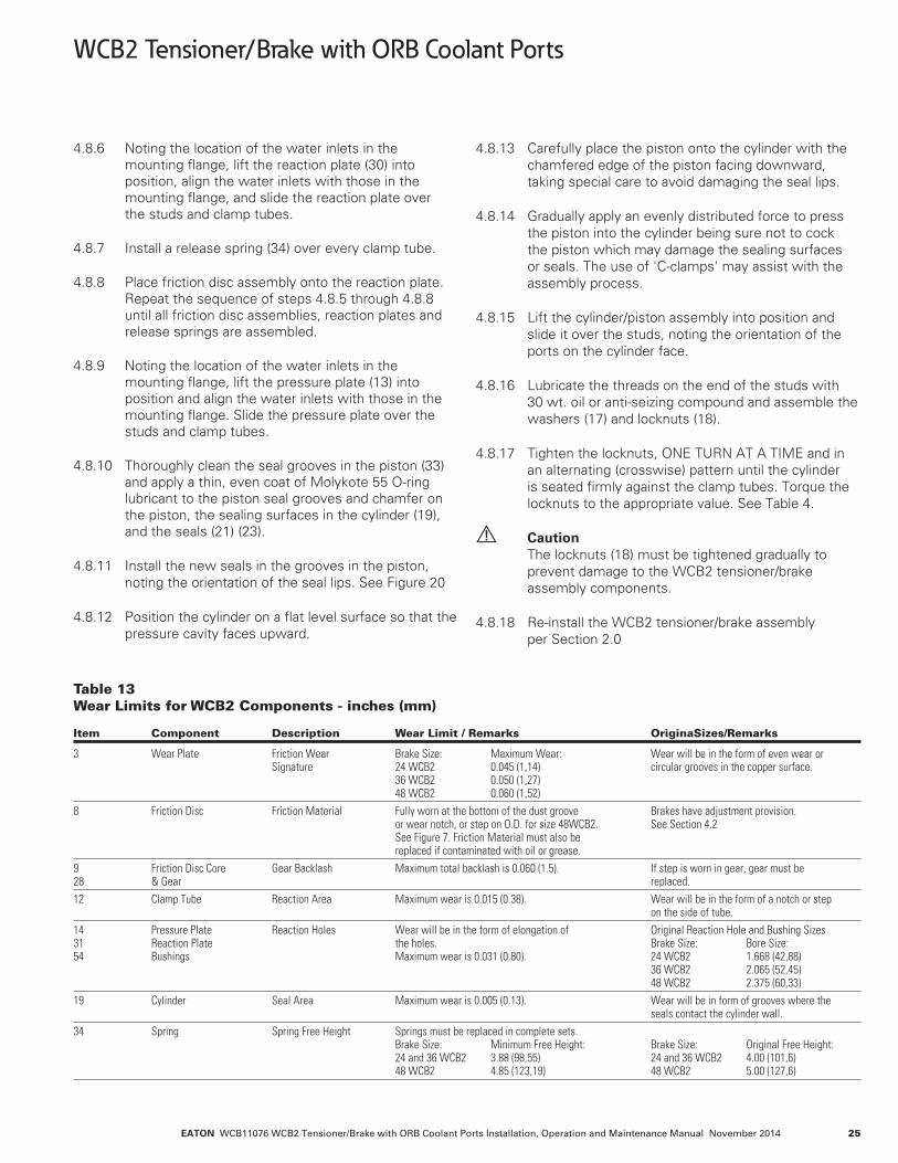
Table 13 Wear Limits for WCB2 Components - inches (mm) Item Component Description Wear Limit / Remarks OriginaSizes/Remarks
3 Wear Plate Friction Wear Brake Size: Maximum Wear: Wear will be in the form of even wear or Signature 24 WCB2 0.045 (1,14) circular grooves in the copper surface. 36 WCB2 0.050 (1,27) 48 WCB2 0.060 (1,52)8 Friction Disc Friction Material Fully worn at the bottom of the dust groove Brakes have adjustment provision. or wear notch, or step on O.D. for size 48WCB2. See Section 4.2 See Figure 7. Friction Material must also be replaced if contaminated with oil or grease.9 Friction Disc Core Gear Backlash Maximum total backlash is 0.060 (1.5). If step is worn in gear, gear must be 28 & Gear replaced.12 Clamp Tube Reaction Area Maximum wear is 0.015 (0.38). Wear will be in the form of a notch or step on the side of tube.14 Pressure Plate Reaction Holes Wear will be in the form of elongation of Original Reaction Hole and Bushing Sizes 31 Reaction Plate the holes. Brake Size: Bore Size: 54 Bushings Maximum wear is 0.031 (0.80). 24 WCB2 1.668 (42,88) 36 WCB2 2.065 (52,45) 48 WCB2 2.375 (60,33)19 Cylinder Seal Area Maximum wear is 0.005 (0.13). Wear will be in form of grooves where the seals contact the cylinder wall.34 Spring Spring Free Height Springs must be replaced in complete sets. Brake Size: Minimum Free Height: Brake Size: Original Free Height: 24 and 36 WCB2 3.88 (98,55) 24 and 36 WCB2 4.00 (101,6) 48 WCB2 4.85 (123,19) 48 WCB2 5.00 (127,6)

EATON WCB11076 WCB2 Tensioner/Brake with ORB Coolant Ports Installation, Operation and Maintenance Manual November 201426
WCB2 Tensioner/Brake with ORB Coolant Ports
4.9 Corrosion Protection
Caution All previously painted areas must be touched up after maintenance or installation to provide corrosion protection.
4.9.1 Clean any contamination, scale, or loose paint from disturbed surfaces.
4.9.2 Touch up any disturbed area with an organic zinc primer.
4.9.3 Paint areas with two coats of a high solid two part, marine grade epoxy paint as per manufacturer's instructions.
5.0 ORDERING INFORMATION/TECHNICAL ASSISTANCE
5.1 Equipment Reference
5.1.1 In any correspondence regarding Airflex equipment, refer to the information on the product nameplate and call or write: Eaton Hydraulics Group USA Airflex Products 9919 Clinton Rd. Cleveland, Ohio 44144 Tel: (216) 281-2211 Fax: (216) 281-3890 www.eaton.com/hydraulics
Loctite®, Locquic®, and Loctite Superflex® are registered trademarks of Henkel Corporation.
Molykote® is a registered trademark of Dow Corning Corporation.
MOLUB-ALLOY® is a trademark of Castrol Industrial Lubricants.
6.0 PARTS & KITS
6.1.1 24WCB2 Parts (Standard) 124 WCB2 224 WCB2 324 WCB2 424 WCB2 146465R 146466R 146467R 146468R Item Description Part Number Qty Part Number Qty Part Number Qty Part Number Qty
1 Mounting Flange Sub Assembly* 515661-01 1 515661-01 1 515661-01 1 515661-01 16 Stud 000245X0069 12 000245X0071 12 000245X0081 12 000245X0082 127 Friction Disc Sub Assembly* 513964-01 1 513964-01 2 513964-01 3 513964-01 412 Clamp Tube 306542-05 12 306542-20 12 306542-23 12 306542-24 1213 Pressure Plate Sub Assembly* 515661-03 1 515661-03 1 515661-03 1 515661-03 117 Flat Washer 000153X0641 12 000153X0641 12 000153X0641 12 000153X0641 1218 Locknut 000110X0073 12 000110X0073 12 000110X0073 12 000110x0073 1219 Cylinder 513264 1 513264 1 513264 1 513264 121 Lip Seal 000402X0023 2 000402X0023 2 000402X0023 2 000402X0023 223 Lip Seal 000402X0024 2 000402X0024 2 000402X0024 2 000402X0024 228 Gear (not included with assembly) 411672 1 410970 1 412433 1 413195 129 Wear Spacer N/A N/A 308396 12 308396 24 308396 3630 Reaction Plate Sub Assembly* N/A N/A 515661-02 1 515661-02 2 515661-02 333 Piston 513317 1 513317 1 513317 1 513317 134 Release Spring 416751-02 12 416751-02 24 416751-02 36 416751-02 48105 Pipe Plug 000077X0021 1 000077X0021 1 000077X0021 1 000077X0021 1*Individual parts breakdown for standard WCB2 sub-assemblies are in Section 6.3
EATON WCB11076 WCB2 Tensioner/Brake with ORB Coolant Ports Installation, Operation and Maintenance Manual November 2014 27
WCB2 Tensioner/Brake with ORB Coolant Ports
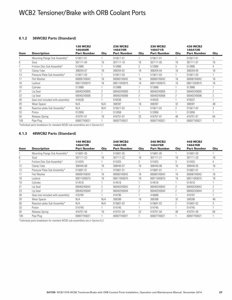
6.1.2 36WCB2 Parts (Standard) 136 WCB2 236 WCB2 336 WCB2 436 WCB2 146469R 146470R 146471R 146472R Item Description Part Number Qty Part Number Qty Part Number Qty Part Number Qty
1 Mounting Flange Sub Assembly* 515617-01 1 515617-01 1 515617-01 1 515617-01 16 Stud 307111-04 16 307111-10 16 307111-05 16 307111-07 167 Friction Disc Sub Assembly* 513990 1 513990 2 513990 3 513990 412 Clamp Tube 308204-07 16 308204-02 16 308204-04 16 308204-05 1613 Pressure Plate Sub Assembly* 515617-03 1 515617-03 1 515617-03 1 515617-03 117 Flat Washer 000067X0042 16 000067X0042 16 000067X0042 16 000067X0042 1618 Locknut 000110X0075 16 000110X0075 16 000110X0075 16 000110X0075 1619 Cylinder 513988 1 513988 1 513988 1 513988 121 Lip Seal 000402X0005 2 000402X0005 2 000402X0005 2 000402X0005 223 Lip Seal 000402X0006 2 000402X0006 2 000402X0006 2 000402X0006 228 Gear (not included with assembly) 416538 1 416536 1 416535 1 416537 129 Wear Spacer N/A N/A 308397 16 308397 32 308397 4830 Reaction plate Sub Assembly* N/A N/A 515617-02 1 515617-02 2 515617-02 333 Piston 512858 1 512858 1 512858 1 512858 134 Release Spring 416751-01 16 416751-01 32 416751-01 48 416751-01 64105 Pipe Plug 000077X0021 1 000077X0021 1 000077X0021 1 000077X0021 1*Individual parts breakdown for standard WCB2 sub-assemblies are in Section 6.3
6.1.3 48WCB2 Parts (Standard) 148 WCB2 248 WCB2 348 WCB2 448 WCB2 146473R 146474R 146475R 146476R Item Description Part Number Qty Part Number Qty Part Number Qty Part Number Qty
1 Mounting Flange Sub Assembly* 515601-05 1 515601-05 1 515601-05 1 515601-05 16 Stud 307111-23 16 307111-22 16 307111-21 16 307111-20 167 Friction Disc Sub Assembly* 514325 1 514325 2 514325 3 514325 412 Clamp Tube 308440-08 16 308440-07 16 308440-06 16 308440-05 1613 Pressure Plate Sub Assembly* 515601-01 1 515601-01 1 515601-01 1 515601-01 117 Flat Washer 000067X0042 16 000067X0042 16 000067X0042 16 000067X0042 1618 Locknut 000110X0075 16 000110X0075 16 000110X0075 16 000110X0075 1619 Cylinder 514516 1 514516 1 514516 1 514516 121 Lip Seal 000402X0042 2 000402X0042 2 000402X0042 2 000402X0042 223 Lip Seal 000402X0044 2 000402X0044 2 000402X0044 2 000402X0044 228 Gear (not included with assembly) 416794 1 416795 1 416688 1 416797 129 Wear Spacer N/A N/A 308398 16 308398 32 308398 4830 Reaction plate Sub Assembly* N/A N/A 515601-02 1 515601-02 2 515601-02 333 Piston 514745 1 514745 1 514745 1 514745 134 Release Spring 416751-04 16 416751-04 32 416751-04 48 416751-04 64105 Pipe Plug 000077X0021 1 000077X0021 1 000077X0021 1 000077X0021 1*Individual parts breakdown for standard WCB2 sub-assemblies are in Section 6.3

EATON WCB11076 WCB2 Tensioner/Brake with ORB Coolant Ports Installation, Operation and Maintenance Manual November 201428
WCB2 Tensioner/Brake with ORB Coolant Ports
6.2.1 24WCB2 Parts (Corrosion Resistant) 124 WCB2 224 WCB2 324 WCB2 424 WCB2 146465RJ 146466RJ 146467RJ 146468RJ Item Description Part Number Qty Part Number Qty Part Number Qty Part Number Qty
1 Mounting Flange Sub Assembly* 515667-01 16 Stud 308160-08 127 Friction Disc Sub Assembly* 514131 412 Clamp Tube 308206-08 1213 Pressure Plate Sub Assembly* 515667-03 117 Flat Washer 000153X0854 1218 Locknut 000110X0076 1219 Cylinder 514039 121 Lip Seal 000402X0023 223 Lip Seal 000402X0024 228 Gear (not included with assembly) 414343 129 Wear Spacer 308407 3630 Reaction Plate Sub Assembly* 515667-02 333 Piston 513924 134 Release Spring 416751-02 48105 Pipe Plug 000077X0021 1N/A Grease 000153X1182 1*Individual parts breakdown for standard WCB2 sub-assemblies are in Section 6.3
6.2.2 36WCB2 Parts (Corrosion Resistant) 136 WCB2 236 WCB2 336 WCB2 436 WCB2 146469RJ 146470RJ 146471RJ 146472RJ Item Description Part Number Qty Part Number Qty Part Number Qty Part Number Qty
1 Mounting Flange Sub Assembly* 515706-01 1 515706-01 1 515706-01 16 Stud 307111-10 16 307111-05 16 307111-07 167 Friction Disc Sub Assembly* 514129 2 514129 3 514129 412 Clamp Tube 308204-02 16 308204-04 16 308204-05 1613 Pressure Plate Sub Assembly* 515706-03 1 515706-03 1 515706-03 117 Flat Washer 000067X0042 16 000153X0850 16 000153X0850 1618 Locknut 000110X0075 16 000110X0075 16 000110X0075 1619 Cylinder 512809 1 512809 1 512809 121 Lip Seal 000402X0005 2 000402X0005 2 000402X0005 223 Lip Seal 000402X0006 2 000402X0006 2 000402X0006 228 Gear (not included with assembly) 416435 1 416435 1 416495 129 Wear Spacer 308400 16 308400 32 308400-05 4830 Reaction plate Sub Assembly* 515706-02 1 515706-02 2 515706-02 333 Piston 513872 1 513872 1 513872 134 Release Spring 416751-01 32 416751-01 48 416751-01 64105 Pipe Plug 000077X0021 1 000077X0021 1 000077X0021 1N/A Grease 000153X1182 2 000153X1182 3 000153X1182 4*Individual parts breakdown for standard WCB2 sub-assemblies are in Section 6.3
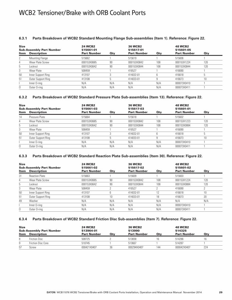
EATON WCB11076 WCB2 Tensioner/Brake with ORB Coolant Ports Installation, Operation and Maintenance Manual November 2014 29
WCB2 Tensioner/Brake with ORB Coolant Ports
6.3.1 Parts Breakdown of WCB2 Standard Mounting Flange Sub-assemblies (Item 1). Reference: Figure 22. Size 24 WCB2 36 WCB2 48 WCB2 Sub-Assembly Part Number 515661-01 515617-01 515601-05 Item Description Part Number Qty Part Number Qty Part Number Qty
2 Mounting Flange 515662 1 515619 1 515606 14 Wear Plate Screw 000153X0685 90 000153X0842 108 000153X1224 1205 Locknut 000153X0642 90 000153X0844 108 000153X0844 1203 Wear Plate 508459 1 416527 1 416690 150 Inner Support Ring 413107 3 414032-01 6 416618 551 Outer Support Ring 413108 5 414033-01 9 416673 10I Inner O-ring N/A N/A N/A N/A 000073X0410 1O Outer O-ring N/A N/A N/A N/A 000073X0411 1
6.3.2 Parts Breakdown of WCB2 Standard Pressure Plate Sub-assemblies (Item 13). Reference: Figure 22. Size 24 WCB2 36 WCB2 48 WCB2 Sub-Assembly Part Number 515661-03 515617-03 515601-01 Item Description Part Number Qty Part Number Qty Part Number Qty
14 Pressure Plate 515664 1 515618 1 515602 14 Wear Plate Screw 000153X0685 90 000153X0842 108 000153X1223 1205 Locknut 000153X0642 90 000153X0844 108 000153X0884 1203 Wear Plate 508459 1 416527 1 416690 150 Inner Support Ring 413107 3 414032-01 6 416618 551 Outer Support Ring 413108 5 414033-01 9 416673 10I Inner O-ring N/A N/A N/A N/A 000073X0410 1O Outer O-ring N/A N/A N/A N/A 000073X0411 1
6.3.3 Parts Breakdown of WCB2 Standard Reaction Plate Sub-assemblies (Item 30). Reference: Figure 22. Size 24 WCB2 36 WCB2 48 WCB2 Sub-Assembly Part Number 515661-02 515617-02 515601-02 Item Description Part Number Qty Part Number Qty Part Number Qty
31 Reaction Plate 515663 1 515609 1 515603 14 Wear Plate Screw 000153X0685 90 000153X0842 108 000153X1224 1205 Locknut 000153X0642 90 000153X0844 108 000153X0884 1203 Wear Plate 508459 2 416527 2 416690 250 Inner Support Ring 413107 6 414032-01 12 416618 1051 Outer Support Ring 413108 10 414033-01 18 416673 2049 Washer N/A N/A N/A N/A N/A N/AI Inner O-ring N/A N/A N/A N/A 000073X0410 1O Outer O-ring N/A N/A N/A N/A 000073X0411 1
6.3.4 Parts Breakdown of WCB2 Standard Friction Disc Sub-assemblies (Item 7). Reference: Figure 22. Size 24 WCB2 36 WCB2 48 WCB2 Sub-Assembly Part Number 513964-01 513990 514325 Item Description Part Number Qty Part Number Qty Part Number Qty
8 Friction Disc 508725 2 513658 16 514286 169 Friction Disc Core 510745 1 513667 1 514287 157 Screw 000421X0407 36 000294X0407 144 000042X0407 224

EATON WCB11076 WCB2 Tensioner/Brake with ORB Coolant Ports Installation, Operation and Maintenance Manual November 201430
WCB2 Tensioner/Brake with ORB Coolant Ports
6.3.5 Parts Breakdown of WCB2 Corrosion Resistant Mounting Flange Sub-assemblies (Item 1). Reference: Figure 22. Size 24 WCB2 36 WCB2 Sub-Assembly Part Number 515667-01 515706-01 Item Description Part Number Qty Part Number Qty
2 Mounting Flange 515662 1 515619 14 Wear Plate Screw 000153X0685 90 000153X0842 1085 Locknut 000153X0856 90 000153X0844 1083 Wear Plate 508459 1 416527 150 Inner Support Ring 413107 3 414032-01 651 Outer Support Ring 413108 5 414033-01 9
6.3.6 Parts Breakdown of WCB2 Corrosion Resistant Pressure Plate Sub-assemblies (Item 13). Reference: Figure 22.
Size 24 WCB2 36 WCB2 Sub-Assembly Part Number 515667-03 515706-03 Item Description Part Number Qty Part Number Qty
14 Pressure Plate 515669 1 515687 14 Wear Plate Screw 000153X0685 90 000153X0842 1085 Locknut 000153X0856 90 000153X0844 1083 Wear Plate 508459 1 416527 150 Inner Support Ring 413107 3 414032-01 651 Outer Support Ring 413108 5 414033-01 954 Bushing 203866-01 12 203863-04 16
6.3.7 Parts Breakdown of WCB2 Corrosion Resistant Reaction Plate Sub-assemblies (Item 30). Reference: Figure 22.
Size 24 WCB2 36 WCB2 Sub-Assembly Part Number 515667-02 515706-02 Item Description Part Number Qty Part Number Qty
31 Reaction Plate 515668 1 515686 14 Wear Plate Screw 000153X0685 90 000153X0843 1085 Locknut 000153X0856 90 000153X0844 1083 Wear Plate 508459 2 416527 250 Inner Support Ring 413107 6 414032-01 1251 Outer Support Ring 413108 10 414033-01 1854 Bushing 203866-04 12 203863-03 16
6.3.8 Parts Breakdown of WCB2 Corrosion Resistant Friction Disc Sub-assemblies (Item 7). Reference: Figure 22. Size 24 WCB2 36 WCB2 Sub-Assembly Part Number 514131 514129 Item Description Part Number Qty Part Number Qty
8 Friction Disc 508725 2 513658 169 Friction Disc Core 514140 1 514139 157 Screw 000421X0407 36 000294X0407 144
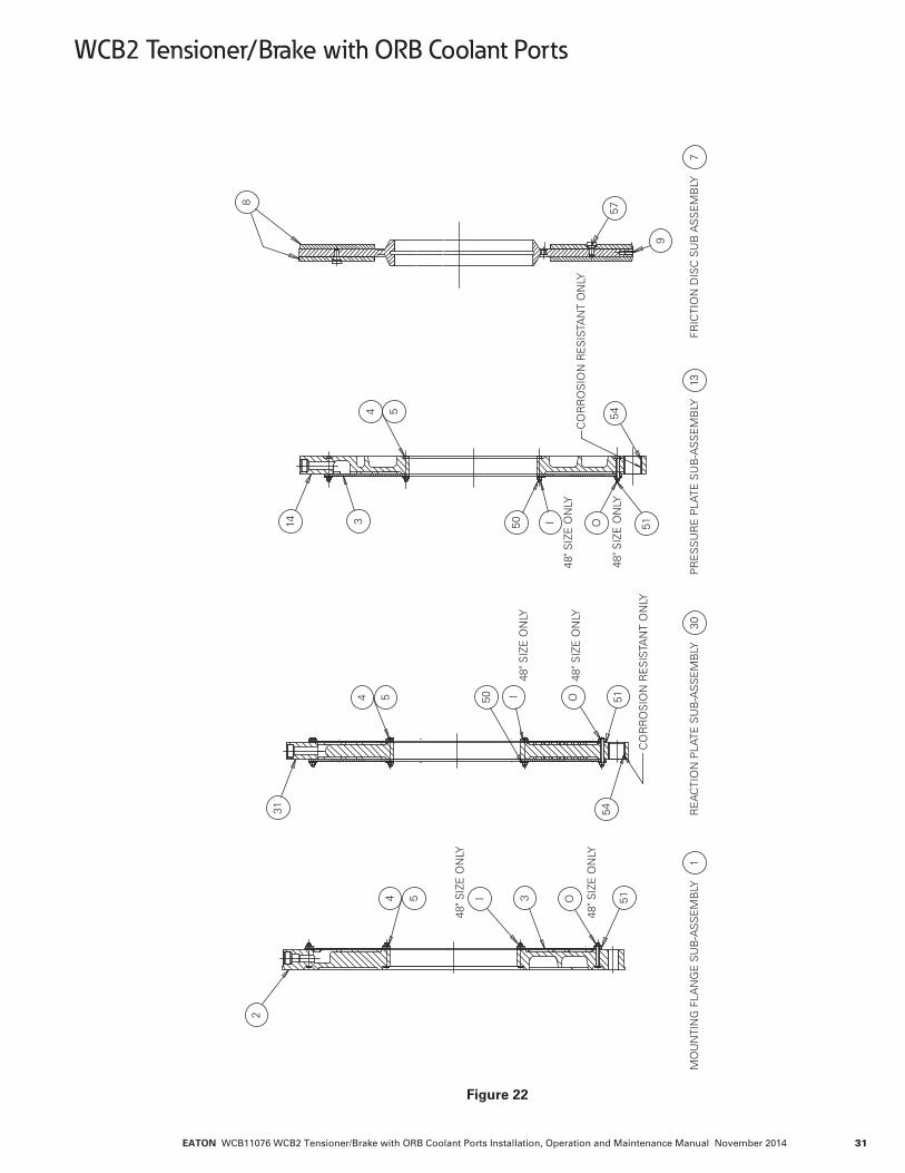
EATON WCB11076 WCB2 Tensioner/Brake with ORB Coolant Ports Installation, Operation and Maintenance Manual November 2014 31
WCB2 Tensioner/Brake with ORB Coolant Ports
48" S
IZE
ON
LY
48" S
IZE
ON
LY
48" S
IZE
ON
LY
48" S
IZE
ON
LY
CO
RR
OS
ION
RE
SIS
TAN
T O
NLY
MO
UN
TIN
G F
LAN
GE
SU
B-A
SS
EM
BLY
RE
AC
TIO
N P
LATE
SU
B-A
SS
EM
BLY
PR
ES
SU
RE
PLA
TE S
UB
-AS
SE
MB
LY
CO
RR
OS
ION
RE
SIS
TAN
T O
NLY
5
55
314
4
5150
54
I O
3 51OI
2
4
31
4
545150
48" S
IZE
ON
LY
48" S
IZE
ON
LYOI
8
9
57
FRIC
TIO
N D
ISC
SU
B A
SS
EM
BLY
130
137
Figure 22
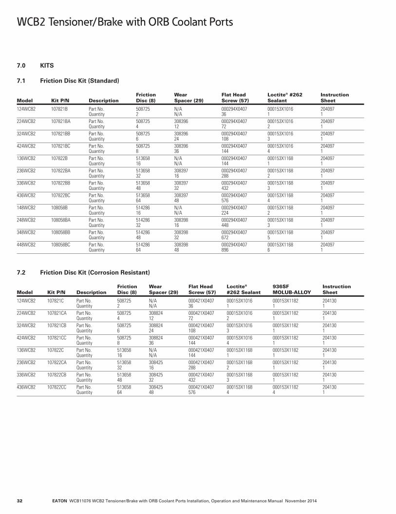
EATON WCB11076 WCB2 Tensioner/Brake with ORB Coolant Ports Installation, Operation and Maintenance Manual November 201432
WCB2 Tensioner/Brake with ORB Coolant Ports
7.0 KITS
7.1 Friction Disc Kit (Standard) Friction Wear Flat Head Loctite® #262 Instruction Model Kit P/N Description Disc (8) Spacer (29) Screw (57) Sealant Sheet
124WCB2 107821B Part No. 508725 N/A 000294X0407 000153X1016 204097 Quantity 2 N/A 36 1 1224WCB2 107821BA Part No. 508725 308396 000294X0407 000153X1016 204097 Quantity 4 12 72 2 1324WCB2 107821BB Part No. 508725 308396 000294X0407 000153X1016 204097 Quantity 6 24 108 3 1424WCB2 107821BC Part No. 508725 308396 000294X0407 000153X1016 204097 Quantity 8 36 144 4 1136WCB2 107822B Part No. 513658 N/A 000294X0407 000153X1168 204097 Quantity 16 N/A 144 1 1236WCB2 107822BA Part No. 513658 308397 000294X0407 000153X1168 204097 Quantity 32 16 288 2 1336WCB2 107822BB Part No. 513658 308397 000294X0407 000153X1168 204097 Quantity 48 32 432 3 1436WCB2 107822BC Part No. 513658 308397 000294X0407 000153X1168 204097 Quantity 64 48 576 4 1148WCB2 108058B Part No. 514286 N/A 000294X0407 000153X1168 204097 Quantity 16 N/A 224 2 1248WCB2 108058BA Part No. 514286 308398 000294X0407 000153X1168 204097 Quantity 32 16 448 3 1348WCB2 108058BB Part No. 514286 308398 000294X0407 000153X1168 204097 Quantity 48 32 672 5 1448WCB2 108058BC Part No. 514286 308398 000294X0407 000153X1168 204097 Quantity 64 48 896 6 1
7.2 Friction Disc Kit (Corrosion Resistant) Friction Wear Flat Head Loctite® 936SF Instruction Model Kit P/N Description Disc (8) Spacer (29) Screw (57) #262 Sealant MOLUB-ALLOY Sheet
124WCB2 107821C Part No. 508725 N/A 000421X0407 000153X1016 000153X1182 204130 Quantity 2 N/A 36 1 1 1224WCB2 107821CA Part No. 508725 308824 000421X0407 000153X1016 000153X1182 204130 Quantity 4 12 72 2 1 1324WCB2 107821CB Part No. 508725 308824 000421X0407 000153X1016 000153X1182 204130 Quantity 6 24 108 3 1 1424WCB2 107821CC Part No. 508725 308824 000421X0407 000153X1016 000153X1182 204130 Quantity 8 36 144 4 1 1136WCB2 107822C Part No. 513658 N/A 000421X0407 000153X1168 000153X1182 204130 Quantity 16 N/A 144 1 1 1236WCB2 107822CA Part No. 513658 308425 000421X0407 000153X1168 000153X1182 204130 Quantity 32 16 288 2 1 1336WCB2 107822CB Part No. 513658 308425 000421X0407 000153X1168 000153X1182 204130 Quantity 48 32 432 3 1 1436WCB2 107822CC Part No. 513658 308425 000421X0407 000153X1168 000153X1182 204130 Quantity 64 48 576 4 4 1

EATON WCB11076 WCB2 Tensioner/Brake with ORB Coolant Ports Installation, Operation and Maintenance Manual November 2014 33
WCB2 Tensioner/Brake with ORB Coolant Ports
7.3 Cylinder Seal Kit Lip Seal Lip Seal Seal Instruction Size Kit P/N Description (Inner) (21) (Outer) (23) Lubricant Sheet
24WCB2 107727C Part No. 000402X0023 000402X0024 000153X1239 204067 Quantity 2 2 1 136WCB2 107662C Part No. 000402X0005 000402X0006 000153X1239 204067 Quantity 2 2 1 148WCB2 108055C Part No. 000402X0042 000402X0044 000153X1239 204067 Quantity 2 2 1 1
7.4 Wear Plate Kit for Mounting Flange and Pressure Plate Inner Outer PTFE PTFE Lock Wear Support Support Gasket Gasket Instruction Size Kit P/N Description Screw (4) Nut (5) Plate (3) Ring (50) Ring (51) (O.D.) (I.D.) Sheet
24WCB2 107727A Part No. 000153X0642 000153X0685 508459 413107 413108 308581-01 308581-02 204063 Quantity 180 180 2 6 10 2 2 136WCB2 107662A Part No. 000153X0842 000153X0844 416527 414032-01 414033-01 308581-01 308581-02 204063 Quantity 216 216 2 12 18 2 2 1 Screw Screw Inner Outer Pressure Mounting Lock Wear Support Support Inner Outer Loctite Instruction Size Kit P/N Description Plate (4) Flange (4) Nut (5) Plate (3) Ring (50) Ring (51) O-Ring (I) O-Ring (O) #596 Sheet
48WCB2 108855A Part No. 000153X1223 000153X1224 000153X0844 416690 416618 416673 000073X0410 000073X0411 000153X1071 204063 Quantity 120 120 240 2 10 20 2 2 3 1
7.5 Wear Plate Kit for Reaction Plate Inner Outer PTFE PTFE Lock Washer Wear Support Suport Gasket Gasket Instruction Size Kit P/N Description Screw (4) Nut (5) (49) Plate (3) Ring (50) Ring (51) (O.D.) (I.D.) Sheet
24WCB2 107727E Part No. 000153X0642 000153X0685 N/A 508459 413107 413108 308581-01 308581-02 204063 Quantity 90 90 2 6 10 2 2 136WCB2 107662E Part No. 000153X0843 000153X0844 N/A 416527 414032-01 414033-01 308581-01 308581-02 204063 Quantity 108 108 2 12 18 2 2 1 Inner Outer Wear Support Suport Lock Plate Ring Ring Inner Outer Loctite Instruction Size Kit P/N Description Screw (4) Nut (5) (3) (50) (51) O-Ring (I) O-Ring (O) #596 Sheet
48WCB2 108855E Part No. 000153X1224 000153X0844 416690 416618 416673 000073X0410 000073 X0411 000153X1071 204063 Quantity 120 120 2 10 20 2 2 3 1
EATON WCB11076 WCB2 Tensioner/Brake with ORB Coolant Ports Installation, Operation and Maintenance Manual November 201434
WCB2 Tensioner/Brake with ORB Coolant Ports
8.0 REVISIONS Original Publication Date: November 2014 Revision Date Change Page

EATON WCB11076 WCB2 Tensioner/Brake with ORB Coolant Ports Installation, Operation and Maintenance Manual November 2014 35
WCB2 Tensioner/Brake with ORB Coolant Ports
User Notes
© 2014 EatonAll Rights ReservedPrinted in USADocument No. WCB11076 November 2014
EatonHydraulics Group USAAirflex Division9919 Clinton RoadCleveland, OH 44144-1077Tel: 216-281-2211Fax: 216-281-3890
EatonHydraulics Group Asia PacificAirflex Division281 Fa Sai RoadWaigaoqiao Free Trade ZoneShanghai 200131ChinaTel:(+8621) 5048-4811Fax:(+8621) 5048-4911