wc bo0158137en 006 - wacker neusonproducts.wackerneuson.com/manuals/operators/0158137en...safety...
TRANSCRIPT

www.wackergroup.com
Light Tower
LTC 4L
OPERATOR’S MANUAL
0158137en 006
1205
0 1 5 8 1 3 7 E N


LTC 4L Table of Contents
1. Foreword 3
2. Safety Information 4
2.1 Laws Pertaining to Spark Arresters ...................................................... 42.2 Operating Safety .................................................................................. 52.3 Operator Safety while using Internal Combustion Engines .................. 62.4 Towing Safety ....................................................................................... 72.5 Service Safety ...................................................................................... 82.6 Label Locations .................................................................................... 92.7 Safety and Operating Labels .............................................................. 11
3. Technical Data—Lombardini 18
3.1 Engine ................................................................................................ 183.2 Generator ........................................................................................... 193.3 Machine .............................................................................................. 20
4. Operation 21
4.1 Locating Trailer ................................................................................... 214.2 Leveling Trailer ................................................................................... 224.3 Adjusting Lights .................................................................................. 224.4 Preparing Trailer for Towing or Lifting ................................................ 234.5 Raising Tower (Manual Winch System) ............................................. 244.6 Lowering Tower (Manual Winch System) ........................................... 274.7 Raising Tower (Power Winch System) ............................................... 294.8 Lowering Tower (Power Winch System) ............................................ 314.9 Emergency Crank Handle (Power Winch System) ............................. 324.10 Control Panels - 60 Hz (Manual Winch System) ................................ 334.11 Control Panels - 60 Hz (Power Winch System) .................................. 344.12 Control Panels - 50 Hz (Manual Winch System)
(0009377 Rev. 103 and higher) .......................................................... 354.13 Control Panels - 50 Hz (Manual Winch System)
(0009377 Rev. 102 and lower) ........................................................... 364.14 Starting ............................................................................................... 374.15 Automatic Shutdown .......................................................................... 374.16 Operating Lights ................................................................................. 384.17 Stopping ............................................................................................. 38
wc_bo0158137en_006TOC.fm 1

Table of Contents LTC 4L
4.18 Derating ...............................................................................................384.19 Receptacles - 60 Hz ............................................................................394.20 Receptacles - 50 Hz ............................................................................395. Maintenance 40
5.1 Installing / Removing Light Fixtures ....................................................405.2 Replacing / Removing Bulbs ...............................................................415.3 Daily Inspection ...................................................................................415.4 Air Cleaner ..........................................................................................425.5 Engine Oil ............................................................................................435.6 Power Winch .......................................................................................435.7 Engine Maintenance ............................................................................445.8 Troubleshooting ...................................................................................455.9 Schematic for 60Hz Metal Halide 4-Light Units
(0009375 Rev. 105 and higher, 0620018 Rev. 102 and higher ) ........465.10 Schematic for 60Hz Metal Halide 4-Light Units
(0009375 Rev. 104 and lower, 0620018 Rev. 101 and lower) ............485.11 Schematic for 50Hz Metal Halide Units
(0009377 Rev. 103 and higher) ...........................................................505.12 Schematic for 50Hz Metal Halide Units
(0009377 Rev. 102 and lower) ............................................................525.13 Generator Capacitor Excitation Schematic 60Hz
(0009375 Rev. 104 and lower, 0620018 Rev. 101 and lower) ............545.14 Generator Capacitor Excitation Schematic 50Hz ................................555.15 Trailer Wiring .......................................................................................565.16 Engine Wiring - Lombardini .................................................................575.17 Control Panel Wiring ...........................................................................585.18 Power Winch Schematic .....................................................................59
wc_bo0158137en_006TOC.fm 2
wc_tx000001gb.fm 3
CALIFORNIA
Proposition 65 Warning:
Engine exhaust, some of its constituents, and certain vehiclecomponents, contain or emit chemicals known to the State ofCalifornia to cause cancer and birth defects or other reproductiveharm.
1. Foreword
This manual provides information and procedures to safely operateand maintain this Wacker model. For your own safety and protectionfrom injury, carefully read, understand and observe the safetyinstructions described in this manual.
Keep this manual or a copy of it with the machine. If you lose thismanual or need an additional copy, please contact WackerCorporation. This machine is built with user safety in mind; however,it can present hazards if improperly operated and serviced. Followoperating instructions carefully! If you have questions about operatingor servicing this equipment, please contact Wacker Corporation.
The information contained in this manual was based on machines inproduction at the time of publication. Wacker Corporation reserves theright to change any portion of this information without notice.
All rights, especially copying and distribution rights, are reserved.
Copyright 2005 by Wacker Corporation.
No part of this publication may be reproduced in any form or by anymeans, electronic or mechanical, including photocopying, withoutexpress written permission from Wacker Corporation.
Any type of reproduction or distribution not authorized by WackerCorporation represents an infringement of valid copyrights and will beprosecuted. We expressly reserve the right to make technicalmodifications, even without due notice, which aim at improving ourmachines or their safety standards.
WARNING
Safety Information LTC 4L
2. Safety Information
This manual contains DANGER, WARNING, CAUTION, and NOTEcallouts which must be followed to reduce the possibility of personalinjury, damage to the equipment, or improper service.
This is the safety alert symbol. It is used to alert you to potentialpersonal injury hazards. Obey all safety messages that follow thissymbol to avoid possible injury or death.
DANGER indicates an imminently hazardous situation which, if notavoided, will result in death or serious injury.
WARNING indicates a potentially hazardous situation which, if notavoided, could result in death or serious injury.
CAUTION indicates a potentially hazardous situation which, if notavoided, may result in minor or moderate injury.
CAUTION: Used without the safety alert symbol, CAUTION indicatesa potentially hazardous situation which, if not avoided, may result inproperty damage.
Note: Contains additional information important to a procedure.
2.1 Laws Pertaining to Spark Arresters
Notice: State Health Safety Codes and Public Resources Codesspecify that in certain locations spark arresters be used on internalcombustion engines that use hydrocarbon fuels. A spark arrester is adevice designed to prevent accidental discharge of sparks or flamesfrom the engine exhaust. Spark arresters are qualified and rated bythe United States Forest Service for this purpose.
In order to comply with local laws regarding spark arresters, consultthe engine distributor or the local Health and Safety Administrator.
DANGER
WARNING
CAUTION
wc_si000114gb.fm 4

LTC 4L Safety Information
2.2 Operating Safety
Familiarity and proper training are required for the safe operation ofequipment. Equipment operated improperly or by untrained personnelcan be dangerous. Read the operating instructions contained in boththis manual and the engine manual and familiarize yourself with thelocation and proper use of all controls. Inexperienced operators shouldreceive instruction from someone familiar with the equipment beforebeing allowed to operate the machine.
2.2.1 The area immediately surrounding the Light Tower should be clean,neat, and free of debris.
2.2.2 ALWAYS be sure the machine is on a firm, level surface and will nottip, roll, slide, or fall while operating.
2.2.3 NEVER start a unit in need of repair.
2.2.4 Lower the tower when not in use, or if high winds or electrical stormsare expected in the area.
2.2.5 ALWAYS make certain the machine is well-grounded and securelyfastened to a good earthen ground per national and local regulations.
2.2.6 The tower extends up to 9 m (30 ft.). Make sure the area above thetrailer is open and clear of overhead wires and obstructions.
2.2.7 The bulbs become extremely hot in use! Allow the bulb and fixture tocool 10–15 minutes before handling.
2.2.8 Keep the area behind the trailer clear of people while raising andlowering the mast! Never raise, lower or turn the mast while unit isoperating!
2.2.9 The trailer must be leveled and the outriggers extended before raisingthe tower. The outriggers must remain extended while the tower is up.
2.2.10 If for any reason any part of the mast hangs up or the winch cabledevelops slack while raising or lowering the tower, STOP immediately!Contact an authorized WACKER service representative.
2.2.11 NEVER remove the mast locking pin while the tower is up!
2.2.12 NEVER use the machine if the insulation on the electrical cord is cut orworn through.
2.2.13 NEVER operate the lights without the protective lens cover in place orwith a lens cover that is cracked or damaged!
2.2.14 NEVER adjust the mast while the unit is operating.
2.2.15 NEVER raise the mast or operate the Light Tower in high winds.
2.2.16 NEVER connect machine to other power sources, such as supplymains of power companies.
2.2.17 ALWAYS replace or repair electrical components with componentsthat are identical in rating and performance as the original component.
WARNING
wc_si000114gb.fm 5

Safety Information LTC 4L
2.3 Operator Safety while using Internal Combustion Engines
Internal combustion engines present special hazards during operationand fueling. Read and follow the warning instructions in the engineowner’s manual and the safety guidelines below. Failure to follow thewarnings and safety guidelines could result in severe injury or death.
2.3.1 NEVER operate the machine indoors unless exhaust fumes can beadequately ventilated.
2.3.2 DO NOT fill or drain the fuel tank near an open flame, while smoking,or while the engine is running.
2.3.3 ALWAYS refill the fuel tank in a well-ventilated area.
2.3.4 DO NOT touch or lean against hot exhaust pipes.
2.3.5 ALWAYS replace the fuel tank cap after refueling.
2.3.6 DO NOT remove radiator cap when the engine is hot. The radiator fluidis hot and under pressure and may cause severe burns!
2.3.7 DO NOT use gasoline or other types of fuels or flammable solvents toclean parts, especially in enclosed areas. Fumes from fuels andsolvents can become explosive.
2.3.8 ALWAYS keep the area around the muffler free of debris such asleaves, paper, cartons, etc. A hot muffler could ignite the debris andstart a fire.
DANGER
wc_si000114gb.fm 6

LTC 4L Safety Information
2.4 Towing Safety
Towing a large trailer requires special care. Both the trailer and vehiclemust be in good condition and securely fastened to each other toreduce the possibility of an accident.
2.4.1 ALWAYS check that the hitch and coupling on the vehicle are ratedequal to, or greater than, the trailer's “gross vehicle weight rating”(GVWR).
2.4.2 ALWAYS inspect the hitch and coupling for wear or damage. DO NOTtow trailer using defective parts.
2.4.3 ALWAYS make sure the coupling is securely fastened to the vehicle.
2.4.4 ALWAYS check the tires on the trailer for tread wear, inflation, andcondition. Replace worn tires.
2.4.5 ALWAYS connect the safety chains.
2.4.6 ALWAYS make sure directional and trailer lights are connected andworking properly.
2.4.7 ALWAYS check that the lug nuts holding the wheels are tight and thatnone are missing.
2.4.8 The maximum recommended speed for highway towing is 72 km/hour(45 MPH). Recommended off-road towing speed is not to exceed 16km/hour (10 MPH) or less depending on terrain.
2.4.9 ALWAYS refer to the applicable Department of Transportationregulations before towing.
WARNING
wc_si000114gb.fm 7
Safety Information LTC 4L
2.5 Service Safety
HIGH VOLTAGE! This unit uses high voltage circuits capable ofcausing serious injury or death. Only a qualified electrician shouldtroubleshoot or repair electrical problems occurring in this equipment.
2.5.1 ALWAYS replace the safety devices and guards after repairs andmaintenance.
2.5.2 Before servicing the Light Tower, make sure the engine start switch isturned to OFF, the circuit breakers are open (off), and the negativeterminal on battery is disconnected. NEVER perform even routineservice (oil/filter changes, cleaning, etc.) unless all electricalcomponents are shut down.
2.5.3 DO NOT allow water to accumulate around the base of the machine.If water is present, move the machine and allow the machine to drybefore servicing.
2.5.4 DO NOT service the machine if your clothing or skin is wet.
2.5.5 ALWAYS keep hands, feet, and loose clothing away from the movingparts on the generator and engine.
2.5.6 ALWAYS keep the machine clean and labels legible. Replace allmissing and hard-to-read labels. Labels provide important operatinginstructions and warn of dangers and hazards.
2.5.7 ALWAYS make sure slings, chains, hooks, ramps, jacks and othertypes of lifting devices are attached securely and have enough weight-bearing capacity to lift or hold the machine safely. Always remainaware of the location of other people around when lifting the machine.
2.5.8 ALWAYS turn off the light circuit breakers and shut down the enginebefore disconnecting the light fixtures or changing the light bulbs.
WARNING
wc_si000114gb.fm 8
LTC 4L Safety Information
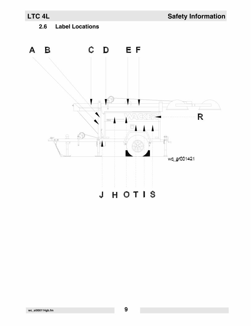
2.6 Label Locations
wc_si000114gb.fm 9
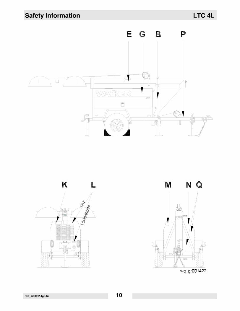
Safety Information LTC 4L
wc_si000114gb.fm 10

LTC 4L Safety Information
2.7 Safety and Operating Labels
Wacker machines use international pictorial labels where needed.These labels are described below:
Ref. Label Meaning
A DANGER! A non-secured, falling mast will cause serious injury or death if a person is hit. To secure mast, verify automatic locking pin has engaged to secure tower upright.
B WARNING! Avoid crushing area.
C WARNING! Completely lower tower before tilting mast. Tilting an extended mast could cause serious injury or death.
D DANGER! Contact with overhead electrical power lines will cause serious injury or death. Do not position Light Tower under electrical power lines.
wc_si000114gb.fm 11

Safety Information LTC 4L
E CAUTION! Lifting point
F WARNING! Secure mast in transport lock before lifting or towing. A loose swinging mast could cause personal injury or machine damage.
G DANGER! Asphyxiation hazard. Read the Opera-tor’s Manual for instructions. No sparks, flames, or burning objects near machine. Stop the engine before adding fuel. Use only diesel fuel.
H DANGER! Asphyxiation hazard. Read the Opera-tor’s Manual for instructions. No sparks, flames, or burning objects near machine. Stop the engine before adding fuel. Use only diesel fuel.
DANGER! Contact with overhead electrical power lines will cause serious injury or death. Do not position Light Tower under electrical power lines.
WARNING! Completely lower tower before tilting mast. Tilting an extended mast could cause serious injury or death.
I DANGER! Electrical storage device within. Contact a qualified electrician for service or to open electrical box. Electric shock will cause serious injury or death.
Ref. Label Meaning
wc_si000114gb.fm 12

LTC 4L Safety Information
J Electrical ground
K WARNING! Stand clear of front and rear of machine when mast is being tilted up or down.
L WARNING! Hot surface!
M A nameplate listing the model number, item number, revision number, and serial number is attached to each unit. Please record the information found on this plate so it will be available should the nameplate become lost or damaged. When ordering parts or requesting service information, you will always be asked to specify the model number, item number, revision number, and serial number of the unit.
N WARNING! Ultraviolet radiation from lamp can cause serious skin and eye irritation. Use only with provided undamaged lens cover and fixture.
Ref. Label Meaning
wc_si000114gb.fm 13

Safety Information LTC 4L
Ref. Label
O
P� � � � � � � � � � � � � � � � � � � � � �� � � � � � � � � � � � � � � � � � � � � � � � � � � � � � � � � � � � � � � � � � � � � � � � � � � � � � � � � � � � �
� � � � � � � � � � � � � � � � � � � � � �
� � � � � � � � � � � � � � � � � � � � � � � � � �
� � � � � � � � � � � � � � � � � � � � � � � � � � �
� � � � � � � � � � � � � � � � � � � � � � � � � � � �
� � � � � � � �
� � � � � � � � � � � � � � � � � � � � � � � � � � � � � �
� � � � � � � �
� � � � � � � � � � � � � � � � � � � �
� � � � � � � � � � � � � � � � � � � � � � � � � �
� � � � � � � � � � � � � � � � � � � � � � � � � � � � !
� � � � � � � � � � � � � � � � � � � � � � � � � � � � � � � �
� � � � � � � � � � �
� � � � � � � � � � � � � � � � � � " � � � � � � " � � �
� � � � � � � � � � �
� � � � � � � � � � � � � � � � � � � � � � � " � � � � � � � � � � � � � � �
� � � � � � � � � � � � � � � � � � � � � � � �
� � � � � � � � � � � � � � � � � � � � � � � �
� � � � � � � � � � � � � � � � � � � � � � � � � � � � � �
� � � � � � � � � � � � � � � � � � � � � � � � � � � � � � � �
� � � � � � � � � � � � � � � � � � � �
� � � � � � � � � � � � � � � � � � � � � � � � � � � � � � � �
� � � � � � � � � � � � � � � � � � � � � � � � � � � �
� � � � # � � � � � � " � � � � � � � � � � � � � � � � � �
� � � � � � � � � � � � � � � � � � � � � � � � � � �
� � � � � � � � � � � � � � � � � � � � � �
� � � � � � � � � � � � � � � � � � � � � � � � � � � � � � � � � � � � � �
� � � � � � � � � � � � � � � � � � � � � � � � � � � � � �
� � � � � � � � �
� � � � � � � � � � � � � � � � � � � � � � � � � � � � � � � � � � � � � �
� � � � � � � � �
� � � � � � � � � � � � � � � � � � � � � � � � � � � � � � � � � � � � � � �
� � � � � � � � � � � � � � � � �
� � � � � � � � � � � � � � � � � � � � � � � � � � � � � ���$%�
wc_si000114gb.fm 14

LTC 4L Safety Information
Q
Ref. Label
Manual Winch System
wc_si000114gb.fm 15

Safety Information LTC 4L
Q
Ref. Label
Power Winch System
wc_si000114gb.fm 16

LTC 4L Safety Information
Ref. Label Meaning
R Coolant overflow bottle only, not a return system.
S WARNING!Pinching hazard. Rotating machinery.
T DO NOT pressure wash the control panel.
Certification Label (VIN Number)Also attached to each unit is a Certification Label. This label specifies that the trailer conforms with all Federal Motor Vehicle Standards in effect at the time of manufacture. The label includes the Vehicle Identification Number (VIN) for the trailer.
MANUFACTURED BY: / FABRIQUE PAR:
GVWR / PNBV KG ( LB) GAWR (EACH AXLE) / PNBE (CHAQUE ESSIEU) KG ( LB) TIRES / PNEU
RIMS / JANTE COLD INFL. PRESS. / PRESS. DE GONFL. A FROID KPA ( PSI / LPC) SINGLE DUAL
THIS VEHICLE CONFORMS TO ALL APPLICABLE U.S. FEDERAL MOTOR VEHICLE SAFETY STANDARDS IN EFFECT ON THE DATE OF MANUFACTURE SHOWN ABOVE.
THIS VEHICLE CONFORMS TO ALL APPLICABLE STANDARDS PRESCRIBED UNDER THE CANADIAN MOTOR VEHICLE SAFETY REGULATIONS IN EFFECT ON THE DATE OF MANUFACTURE. CE VEHICULE EST
CONFORME A TOUTES LES NORMES QUI LUI SONT APPLICABLES EN VERTU DU REGLEMENT SUR LA SECURITE DES VEHICULES AUTOMOBILES DU CANADA EN VIGUEUR A LA DATE DE SA FABRICATION.
V.I.N. / N.I.V. TYPE / TYPE: TRAILER TRA / REM
DATE
wc_si000114gb.fm 17

Technical Data—Lombardini LTC 4L
3. Technical Data—Lombardini
3.1 Engine
Item Number: LTC 4L - 60 Hz0009311
0009375 Rev.102 & lower
LTC 4L - 60 Hz
0009375 Rev.103 & above,
0620018
LTC 4L - 50 Hz0009377
Engine
Make Lombardini
Model LDW903 LDW1003
Type 3-cylinder, 4-cycle, liquid-cooled diesel
Maximum power rating kW (Hp) 9.0 (12.1) 10 (13.4) 8.5 (11.4)
Operating power rating kW (Hp) 8.1 (10.9) 9.1 (12.2) 7.6 (10.2)
Operating speed (no-load)
rpm 1850 1800 1550
Alternator V / A / W 12 / 45 / 540
Battery V/Ah/CCA 12 / 450
Air cleaner type dry-type element
Fuel type No. 2 diesel
Fuel tank capacity l (gal.) 114 (30)
Fuel consumption l (gal.) / hr. 1.67 (0.44) 1.70 (0.45)
Running time hours 65 66.7
Coolant capacity l (qts.) 4.7 (5.0)
Oil capacity l (qts.) 2.4 (2.5)
Oil weight SAE 15W40 CD or higher
wc_td000114gb.fm 18

LTC 4L Technical Data—Lombardini
3.2 Generator
Item Number: LTC 4L - 60 Hz0009311, 0009375
0620018
LTC 4L - 50 Hz0009377
Generator
Frequency Hz 60 ± 2 50 ± 2
Continuous output kW 6.0 5.0
Output volts/phase 120 / 240, 1Ø 115 / 230, 1Ø
Amps A 50 / 25 43.5 / 21.7
Excitation type Capacitor / Brushless
Power factor 1.0
Voltage regulation - No load to full load
% ± 5.0
Speed (no-load) rpm 1850 1550
wc_td000114gb.fm 19

Technical Data—Lombardini LTC 4L
3.3 Machine
Item Number: LTC 4L0009311
LTC 4L000937500093770620018
LTC 4C00093760009378
LTC 4C0620017
LTC 4C0620028
Machine
Operating weight (GVWR)
kg(lbs.)
818(1804)
825(1820)
827(1824)
832(1834)
Travel Dimensions (l x w x h)
cm (in.) 441 x 163 x 160(173 x 64 x 63)
Trailer length cm (in.) 335 (132)
Height - mast extended
m (ft.)9 (30)
Lighting system (1000W)
4
Ballast Coil and core
Max. lighting coverage@ 0.5 ft. candles
m2
(acres)Metal Halide - 30,400 (7)
High Pressure Sodium - 39,000 (9)
Sound level at 7 m(23 ft.)
dB(A)71 72 71
Tires size ST175 / 80D13
wc_td000114gb.fm 20

LTC 4L Operation
4. Operation
4.1 Locating Trailer
See Graphic: wc_gr0001420
4.1.1 For maximum light coverage locate the Light Tower at ground level orin a spot higher than the area being lighted.
4.1.2 Position the trailer on a firm, flat surface clear of overhead wires andobstructions. Be sure that there is enough area for outriggerextensions to be fully extended.
4.1.3 Connect the ground stud (l) located on the trailer frame, to a goodearthen ground. Consult local codes for proper grounding techniques.
The tower extends up to 9 m (30 ft.). Make sure the area above thetrailer is open and clear of overhead wires and obstructions.
WARNING
wc_tx000292gb.fm 21
Operation LTC 4L
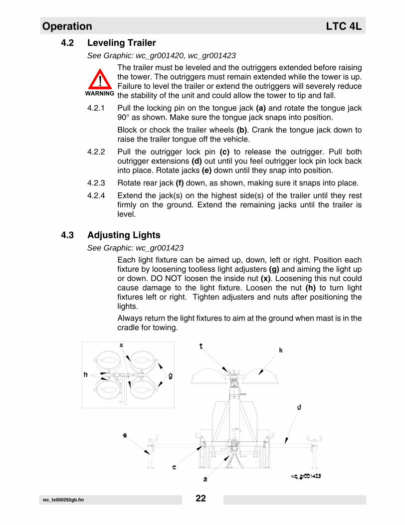
4.2 Leveling TrailerSee Graphic: wc_gr001420, wc_gr001423
The trailer must be leveled and the outriggers extended before raisingthe tower. The outriggers must remain extended while the tower is up.Failure to level the trailer or extend the outriggers will severely reducethe stability of the unit and could allow the tower to tip and fall.
4.2.1 Pull the locking pin on the tongue jack (a) and rotate the tongue jack90° as shown. Make sure the tongue jack snaps into position.
Block or chock the trailer wheels (b). Crank the tongue jack down toraise the trailer tongue off the vehicle.
4.2.2 Pull the outrigger lock pin (c) to release the outrigger. Pull bothoutrigger extensions (d) out until you feel outrigger lock pin lock backinto place. Rotate jacks (e) down until they snap into position.
4.2.3 Rotate rear jack (f) down, as shown, making sure it snaps into place.
4.2.4 Extend the jack(s) on the highest side(s) of the trailer until they restfirmly on the ground. Extend the remaining jacks until the trailer islevel.
4.3 Adjusting LightsSee Graphic: wc_gr001423
Each light fixture can be aimed up, down, left or right. Position eachfixture by loosening toolless light adjusters (g) and aiming the light upor down. DO NOT loosen the inside nut (x). Loosening this nut couldcause damage to the light fixture. Loosen the nut (h) to turn lightfixtures left or right. Tighten adjusters and nuts after positioning thelights.
Always return the light fixtures to aim at the ground when mast is in thecradle for towing.
WARNING
wc_tx000292gb.fm 22

LTC 4L Operation
4.4 Preparing Trailer for Towing or Lifting
See Graphic: wc_gr001423, wc_gr002166
4.4.1 Check that the mast cradle lock pin (j) is in place and secured with thesafety pin.
4.4.2 Ensure that the tower is completely nested inside the transport cradleand the pin (t) is secure.
4.4.3 Make sure the doors are properly latched.
4.4.4 Return the outriggers to their travel position. Check that the outriggerbars and jacks are locked in place.
4.4.5 Crank the rear jack (f) all the way in and rotate it 90°.
The the Light Tower is now ready to lift. For towing, continue.
4.4.6 Use the tongue jack (a) to raise the trailer tongue up and then lower itover hitch on towing vehicle. Lock the hitch to coupling and attach thesafety chains. Swivel the tongue jack 90° and lock it in place.
4.4.7 Connect the trailer wiring to the towing vehicle. Check the brake, turn,and tail lights for proper operation.
4.4.8 Position the light fixtures down (k). For rough, off-road transportationremove bulbs from fixtures to avoid damage.
4.4.9 Check the tire inflation.
4.4.10 Attach a red flag to the end of mast before towing.
CAUTION: Maximum recommended speed for highway towing is 72km/hour (45 MPH). Recommended off-road towing speed is not toexceed 16 km/hour (10 MPH) or less depending on terrain.
wc_tx000292gb.fm 23
Operation LTC 4L
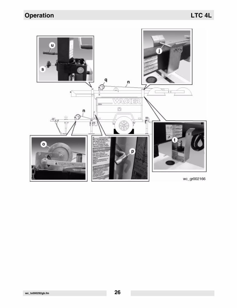
4.5 Raising Tower (Manual Winch System)
See Graphic: wc_gr002166
NEVER raise the mast or operate the Light Tower in high winds.
NEVER raise the mast while the engine is running.
HIGH VOLTAGE! DO NOT use the Light Tower if insulation onelectrical cord is cut or worn through. Repair or replace the cord beforeusing. Bare wires in contact with the metal frame of the trailer or towercan cause electrocution.
DO NOT position the Light Tower under electrical power lines.
NEVER allow anyone to stand near the rear of the unit while raising themast.
The Light Tower includes two separate winches. One for lifting themast to the vertical position, the other for raising the tower. Each winchis an automatic brake-type winch that automatically brakes when thehandle is released. The handle must be rotated to wind in cable as wellas unwind cable.
NEVER touch the winch pawl! Releasing the pawl may cause themast or tower to fall.
4.5.1 Check winch cables (n) for wear or damage, and make sure they areresting properly in pulleys. Do not use the Light Tower if either winchcable is damaged.
4.5.2 Remove the cradle locking pin (j) from the cradle.
4.5.3 Check the operation of the tongue-mounted winch (o) by rotating thewinch handle 1/4-turn clockwise (“cable in” direction). The winch pawlmust engage winch gear teeth. When operating properly, the winchpawl will make a “clicking” sound when the winch handle is rotatedclockwise. Do not attempt to raise the mast if the winch is damaged ornot operating properly.
4.5.4 Continue to rotate the winch handle and raise the mast to the verticalposition until the vertical mast locking pin (p) locks the mast in place.Be certain the vertical mast locking pin is fully engaged in the lockingposition before raising the tower.
WARNING
WARNING
WARNING
WARNING
wc_tx000292gb.fm 24

LTC 4L Operation
NEVER pull the vertical mast locking pin (p) while the tower israised! Releasing the vertical mast locking pin while the tower israised may cause the tower to fall or the machine to tip over.
4.5.5 After the mast is in the vertical position, check the operation of themast-mounted winch (q) by rotating the winch handle 1/4-turnclockwise (“cable in” direction). The winch pawl must engage winchgear teeth. When operating properly, it will make a “clicking” soundwhen the winch handle is rotated clockwise. Do not attempt to raise themast if the winch is damaged or not operating properly. Continuerotating the winch handle until mast is at the desired height. Do notover crank the winch when the tower is fully extended.
CAUTION: Do not extend the tower beyond the red marking on themast!
4.5.6 Once the tower is at the desired height, rotate the mast to the desireddirection. To rotate, loosen rotation locking knob (s). Then using thehandle (u), rotate the mast until the lights face the desired direction,and then retighten the rotation locking knob.
WARNING
wc_tx000292gb.fm 25
Operation LTC 4L
wc_tx000292gb.fm 26

LTC 4L Operation
4.6 Lowering Tower (Manual Winch System)
See Graphic: wc_gr002166
Be sure to read and understand the operating instructions beforelowering the tower!
If for any reason a part of the mast hangs up or a winch cable developsslack before mast is fully lowered, stop immediately! Continuing toturn the winch handle will increase the slack in the cable. Too muchslack could cause the mast to collapse should it suddenly free up. If themast hangs up, level the trailer. Slightly shake or twist the towerassembly to free the bind. Contact an authorized WACKER servicerepresentative immediately.
NEVER lower the mast while the unit is operating.
NEVER allow anyone to stand near the rear of the unit while loweringthe mast.
4.6.1 Turn the lights off. Shut down the engine.
CAUTION: Shutting down the engine before turning off the lights coulddamage floodlight ballasts or generator capacitor(s).
CAUTION: Observe power cord while lowering the tower. Make surethe coiled cord is not damaged during the lowering process.
4.6.2 Lower the tower by turning the handle on the mast-mounted winch (q)counterclockwise (“cable out” direction).
NEVER touch the winch pawl! Releasing the winch pawl may causethe mast or tower to fall.
4.6.3 Loosen the rotation locking knob (s) and using the handle (u), rotatethe mast so the lights face the rear of the trailer and the mast-mountedwinch is facing toward the trailer tongue.
WARNING
WARNING
WARNING
WARNING
wc_tx000292gb.fm 27

Operation LTC 4L
4.6.4 Pull and hold the mast locking pin (p). Rotate the handle on the tongue-mounted winch (o) counterclockwise (“cable out” direction) until themast spring begins to pivot the mast down. Release the mast lockingpin and continue to rotate the handle until the mast is resting in thetransport cradle. Be sure that the secondary locking pin (t) penetratesall sections of the mast.
NEVER pull the vertical mast locking pin (e) while the tower israised! Releasing the locking pin while the tower is raised may causethe tower to fall or the machine to tip over.
4.6.5 After the mast is down, secure it in the cradle by inserting the cradlelock pin (j). Insert the clip through the pin to secure it in place.
4.6.6 Position the light fixtures to aim at the ground.
CAUTION: Allow the floodlights to cool 10–15 minutes before movingtrailer. Moving the trailer while the lights are still hot could cause thebulbs to break.
WARNING
wc_tx000292gb.fm 28

LTC 4L Operation
4.7 Raising Tower (Power Winch System)
See Graphic: wc_gr002759, wc_gr002758
ALWAYS observe the tower while raising and lowering the mast.
NEVER raise the mast or operate the Light Tower in high winds.
NEVER raise the mast while the engine is running.
HIGH VOLTAGE! DO NOT use Light Tower if insulation on electricalcord is cut or worn through. Repair or replace cord before using. Barewires in contact with the metal frame of the trailer or the Light Towercan cause electrocution.
DO NOT position the Light Tower under electrical power lines.
NEVER allow anyone to stand near the rear of the unit while raising themast.
The Light Tower includes two separate winches. One for lifting themast to the vertical position, the other for raising the tower.
4.7.1 Check the winch cables (n) for wear or damage, and make sure theyare resting properly in the pulleys. Do not use the Light Tower if eitherwinch cable is damaged.
4.7.2 Remove the cradle locking pin (j) from the cradle.
4.7.3 Check the operation of the tongue-mounted winch (o). Turn the verticalrotary switch (v) on the control panel to the up position. Do not attemptto raise the mast if the winch is damaged or not operating properly.
CAUTION: Continuous running of the winch in excess of 4 minutes willdamage the winch motor.
Note: It is normal for smoke to be produced during the first fewoperations of a new power winch.
4.7.4 Hold the switch in the up position and raise the mast to the verticalposition until the vertical mast locking pin (p) locks the mast in place.Be certain the vertical mast locking pin is fully engaged in the lockingposition before raising the tower.
NEVER pull the vertical mast locking pin (p) while the tower israised! Releasing the vertical mast locking pin while tower is raisedmay cause the tower to fall or the machine to tip over.
WARNING
WARNING
WARNING
WARNING
wc_tx000292gb.fm 29

Operation LTC 4L
4.7.5 After the mast is in the vertical position, check ther operation of themast-mounted winch (q). Turn the telescope rotary switch (w) on thecontrol panel to the up position. Do not attempt to raise the mast if thewinch is damaged or not operating properly. Continue to hold switch inthe up position until mast is at the desired height. Release switch whentower is fully extended.
CAUTION: Continuous running of the winch in excess of 4 minutes willdamage the winch motor.
CAUTION: Do not extend tower beyond red marking on mast!
4.7.6 Once the tower is at the desired height, rotate the mast to the desireddirection. To rotate, loosen rotation locking knob (s). Then using thehandle (u), rotate the mast until the lights face the desired directionand then retighten rotation locking knob.
wc_tx000292gb.fm 30
LTC 4L Operation
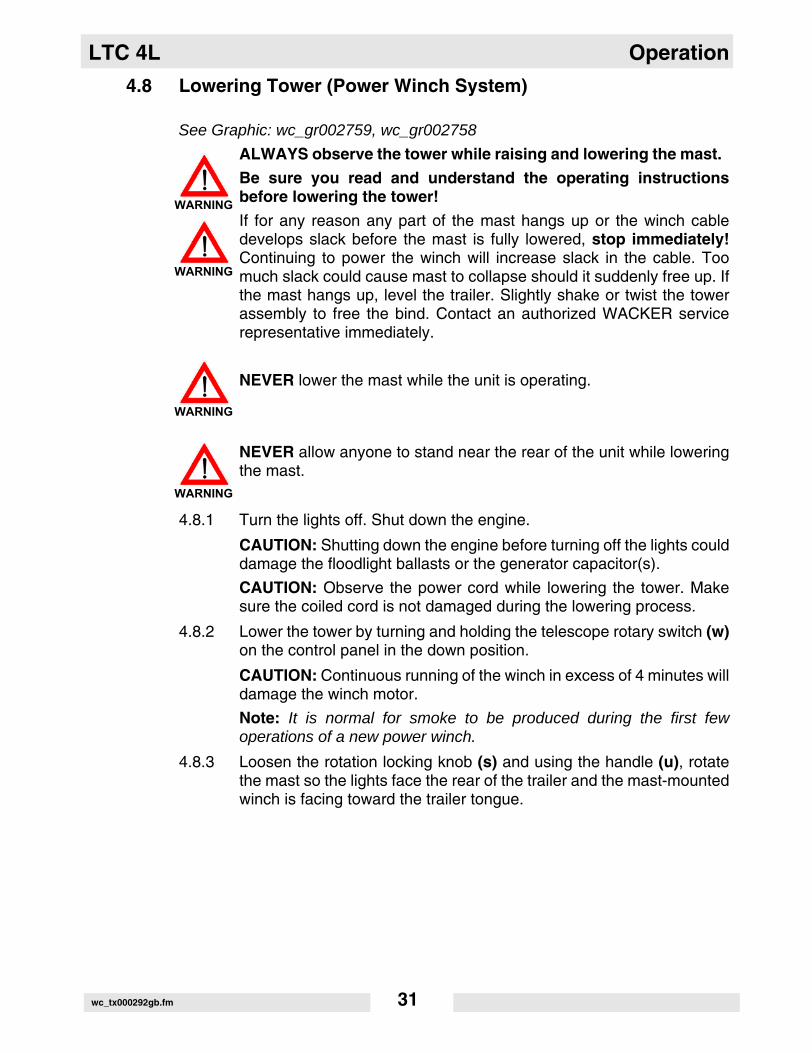
4.8 Lowering Tower (Power Winch System)
See Graphic: wc_gr002759, wc_gr002758
ALWAYS observe the tower while raising and lowering the mast.
Be sure you read and understand the operating instructionsbefore lowering the tower!
If for any reason any part of the mast hangs up or the winch cabledevelops slack before the mast is fully lowered, stop immediately!Continuing to power the winch will increase slack in the cable. Toomuch slack could cause mast to collapse should it suddenly free up. Ifthe mast hangs up, level the trailer. Slightly shake or twist the towerassembly to free the bind. Contact an authorized WACKER servicerepresentative immediately.
NEVER lower the mast while the unit is operating.
NEVER allow anyone to stand near the rear of the unit while loweringthe mast.
4.8.1 Turn the lights off. Shut down the engine.
CAUTION: Shutting down the engine before turning off the lights coulddamage the floodlight ballasts or the generator capacitor(s).
CAUTION: Observe the power cord while lowering the tower. Makesure the coiled cord is not damaged during the lowering process.
4.8.2 Lower the tower by turning and holding the telescope rotary switch (w)on the control panel in the down position.
CAUTION: Continuous running of the winch in excess of 4 minutes willdamage the winch motor.
Note: It is normal for smoke to be produced during the first fewoperations of a new power winch.
4.8.3 Loosen the rotation locking knob (s) and using the handle (u), rotatethe mast so the lights face the rear of the trailer and the mast-mountedwinch is facing toward the trailer tongue.
WARNING
WARNING
WARNING
WARNING
wc_tx000292gb.fm 31

Operation LTC 4L
4.8.4 Pull and hold the mast locking pin (p). Turn and hold the vertical rotaryswitch (v) on the control panel in the down position until the mast isresting in the transport cradle. Be sure that the secondary locking pin(t) penetrates all sections of the mast.
CAUTION: Continuous running of the winch in excess of 4 minutes willdamage the winch motor.
NEVER pull the vertical mast locking pin (e) while the tower israised! Releasing the vertical mast locking pin while the tower israised may cause the tower to fall or the machine to tip over.
4.8.5 After the mast is down, secure it in the cradle by inserting the cradlelock pin (j). Insert the clip through the pin to secure it in place.
4.8.6 Position the light fixtures to aim at the ground.
CAUTION: Allow the floodlights to cool 10–15 minutes before movingthe trailer. Moving the trailer while the lights are still hot could causebulbs to break.
4.9 Emergency Crank Handle (Power Winch System)
An emergency crank handle is provided for use in the event of a powerfailure.
4.9.1 Remove the electrical power from the winch.
4.9.2 Remove the plug from the side of the winch cover. Insert the handle sothat it completely engages with the drive shaft. The handle can becranked in either direction.
4.9.3 Always remove the handle from the winch after use and replace theplug.
NEVER operate the winch electrically with the emergency crankhandle in position.
WARNING
WARNING
wc_tx000292gb.fm 32

LTC 4L Operation
4.10 Control Panels - 60 Hz (Manual Winch System)
Floodlight Control Panel Engine Control Panel
Ref. Description Ref. Description
a 50 Amp circuit breaker k High coolant temperature shutdown
b 15 Amp lights circuit breaker l Alternator indicator
c 20 Amp GFI circuit breaker m Auxiliary light (not used)
d 20 Amp GFI receptacle n Glow plug indicator
e Hour meter o Air filter restriction indicator
f Low fuel indicator (not used) p Auxiliary light (not used)
g Safety shutdown indicator q Key access door
h Low oil pressure shutdown
wc_tx000292gb.fm 33

Operation LTC 4L
4.11 Control Panels - 60 Hz (Power Winch System)
Floodlight Control Panel Engine Control Panel
Ref. Description Ref. Description
a 50 Amp circuit breaker l Alternator indicator
b 15 Amp lights circuit breaker m Auxiliary light (not used)
c 20 Amp GFI circuit breaker n Glow plug indicator
d 20 Amp GFI receptacle o Air filter restriction indicator
e Hour meter p Auxiliary light (not used)
f Low fuel indicator (not used) q Key access door
g Safety shutdown indicator v Tilt rotary switch
h Low oil pressure shutdown w Telescope rotary switch
k High coolant temperature shutdown
wc_tx000292gb.fm 34
LTC 4L Operation
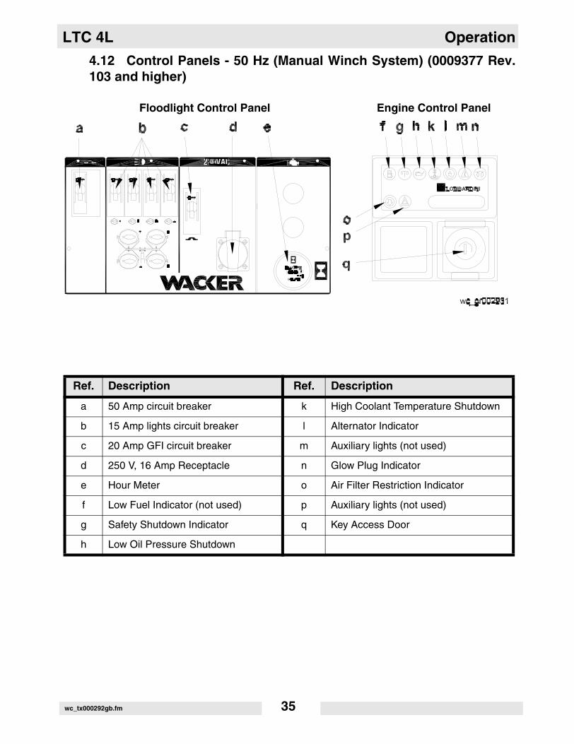
4.12 Control Panels - 50 Hz (Manual Winch System) (0009377 Rev.103 and higher)
Floodlight Control Panel Engine Control Panel
Ref. Description Ref. Description
a 50 Amp circuit breaker k High Coolant Temperature Shutdown
b 15 Amp lights circuit breaker l Alternator Indicator
c 20 Amp GFI circuit breaker m Auxiliary lights (not used)
d 250 V, 16 Amp Receptacle n Glow Plug Indicator
e Hour Meter o Air Filter Restriction Indicator
f Low Fuel Indicator (not used) p Auxiliary lights (not used)
g Safety Shutdown Indicator q Key Access Door
h Low Oil Pressure Shutdown
wc_tx000292gb.fm 35

Operation LTC 4L
4.13 Control Panels - 50 Hz (Manual Winch System) (0009377 Rev.102 and lower)
Floodlight Control Panel Engine Control Panel
Ref. Description Ref. Description
a 50 Amp circuit breaker k High Coolant Temperature Shutdown
b 15 Amp lights circuit breaker l Alternator Indicator
c 20 Amp GFI circuit breaker m Auxiliary lights (not used)
d 250 V, 16 Amp Receptacle n Glow Plug Indicator
e Hour Meter o Air Filter Restriction Indicator
f Low Fuel Indicator (not used) p Auxiliary lights (not used)
g Safety Shutdown Indicator q Key Access Door
h Low Oil Pressure Shutdown r 25 Amp Earth-leakage circuit breaker
wc_tx000292gb.fm 36
LTC 4L Operation
4.14 Starting
See Graphic: wc_gr001068, wc_gr001426, wc_gr002758
4.14.1 Check the engine oil, fuel and coolant levels.
Note: If the fuel tank was drained or run dry it may be necessary tobleed the fuel lines. Refer to the Engine Operator’s Manual.
4.14.2 Check the condition of the electrical cable on the mast. Do not start thegenerator if the insulation on the cable is cut or worn through.
4.14.3 Check that the circuit breakers (a, b, c) are in their OFF position.
CAUTION: Starting the engine under load will damage the machine.
4.14.4 On machines equipped with the Lombardini engine, turn the key (q)one click to the right. The glow plug indicator (n) will illuminate until theengine is properly preheated. This is an automatic timer based on theengine temperature. Crank the engine immediately after the glow pluglight goes off.
4.14.5 Turn the key (q) to START and hold until the engine starts. Releasethe key after engine starts.
CAUTION: Do not crank the engine longer than 10 seconds. Thiscould cause starter motor to overheat. Return switch to OFF and wait15-30 seconds for the starter motor to cool down before attempting topreheat and restart.
Note: If the oil pressure is not obtained within 30 seconds after the keyis turned to RUN, the automatic shutdown system will shut off the fuelsupply. You must return the key to the OFF position to restart the 30second timer before attempting to restart the engine.
4.14.6 Allow the engine to warm up before operating the floodlights.
4.15 Automatic Shutdown
This unit is equipped with a low oil, high temperature auto-shutdownsystem. This system will automatically shut off the fuel supply to theengine if the oil pressure drops too low or the engine exceeds normaloperating temperatures. Return the key switch to “OFF” to reset theunit after an engine shutdown.
wc_tx000292gb.fm 37
Operation LTC 4L
4.16 Operating Lights
See Graphic: wc_gr001068, wc_gr001426, wc_gr002758
Turn on the circuit breaker (a) first, then turn each circuit breaker (b) to“ON”, one at a time.
Metal halide floodlights require a warm-up time of 5–15 minutes beforethey reach full output. If the floodlights are shut down, a 10-minutecool-down period is required before turning them back on.
High pressure sodium floodlights require 1–2 minutes to start and 2–5minutes of cooldown time to restart.
4.17 Stopping
See Graphic: wc_gr001068, wc_gr001426, wc_gr002758
4.17.1 Turn the circuit breakers (a, b, c) off and remove any other loads fromthe generator.
CAUTION: Never shut down the engine without turning off the lights.Damage to the generator will occur.
4.17.2 Turn the key (q) to OFF.
4.18 Derating
All generator sets are subject to derating for altitude and temperature.Although derating should not affect operation of the floodlights, it willreduce the available reserve power to the receptacle.
Ratings are typically reduced 3% per 300 m (1000 feet) elevation fromsea level, and 2% per 10°F (5.5°C) increase in ambient temperatureabove 78°F (25°C).
wc_tx000292gb.fm 38

LTC 4L Operation
4.19 Receptacles - 60 Hz
See Graphic: wc_gr001426, wc_gr002758
The control panel is equipped with a convenience receptacle forrunning accessories and tools from the generator. Power to thisreceptacle is available any time the engine is running and the circuitbreaker is “ON”.
CAUTION: Do not draw more than 2000 Watts from the receptaclewith all of the lights on or the lights will turn off.
A circuit breaker (c) protects the Ground Fault Interrupt (GFI)receptacle (d). The GFI receptacle should be tested for properoperation each time it is used.
To test a GFI:
Push the test button in. The reset button should pop out. Power to thereceptacle is now off. To restore power to receptacle, push resetbutton in.
CAUTION: If the reset button does not pop out, the GFI is defective.Do not use the receptacle until the problem can be corrected.
If the reset button pops out during use, check the generator andattachments for defects.
4.20 Receptacles - 50 Hz
See Graphic: wc_gr001068
The control panel is equipped with a convenience receptacle forrunning accessories and tools from the generator. Power to thisreceptacle is available any time the engine is running and the circuitbreaker is “ON”.
CAUTION: Do not draw more than 2000 Watts from the receptaclewith all of the lights on.
A 20A circuit breaker (c) protects the 250V receptacle (d).
wc_tx000292gb.fm 39

Maintenance LTC 4L
5. Maintenance
5.1 Installing / Removing Light Fixtures
See Graphic: wc_gr001427, wc_gr000542
ALWAYS turn off light circuit breakers and shut down engine beforedisconnecting light fixtures or changing light bulbs.
Remove fixtures by disconnecting electrical cords using the quickdisconnects (a) or by disconnecting electrical cords at the junction box(b). Remove nuts (c) from fixture mounting brackets and remove bothfixture and bracket off stud.
CAUTION: Only a trained technician should be allowed to install andremove fixture wiring.
Note: When reinstalling the lamp fixtures, make sure the drain hole ispointing down.
Bulbs become extremely hot in use! Allow bulb and fixture to cool10-15 minutes before handling.
Numbering Sequence of Floodlights Junction Box Wiring for Floodlights
Wire Colors
B Black R Red Y Yellow Or Orange
G Green T Tan Br Brown Pr Purple
L Blue V Violet Cl Clear Sh Shield
P Pink W White Gr Gray LL Light blue
WARNING
WARNING
wc_tx000293gb.fm 40

LTC 4L Maintenance
5.2 Replacing / Removing Bulbs
The Light Tower uses four 1000W bulbs. When replacing or removingthe bulbs, avoid leaving any grease or oil residue on the glass surface.This can create hot spots, reducing the service life of the bulb orcausing the outer jacket to burst.
ALWAYS turn off the light circuit breakers and shut down the enginebefore disconnecting the light fixtures or changing the light bulbs.
Bulbs become extremely hot in use! Allow the bulb and fixture tocool 10–15 minutes before handling.
NEVER operate the lights without the protective lens cover inplace or with a lens cover that is cracked or damaged! The lampsused in the floodlights produce high temperatures and operate underpressure. They are subject to failures where the outer jacket burstsand shatters, resulting in a discharge of extremely hot glass particles.These particles pose a risk of personal injury, property damage, burnsand fire.
Ultraviolet radiation from the lamp can cause serious skin and eyeirritation. Use the lamp only with provided undamaged lens cover andfixture.
5.3 Daily Inspection
5.3.1 Check for fluid leaks. Check fluid levels.
5.3.2 Inspect condition of electrical cords. Do not use light tower if insulationis cut or worn through.
5.3.3 Check that winch cables are in good condition. Do not use a cable thatis kinked or starting to unravel.
5.3.4 Check that the vertical mast locking pin and its spring are secured,aligned, and operating properly.
WARNING
WARNING
WARNING
wc_tx000293gb.fm 41

Maintenance LTC 4L
5.4 Air Cleaner
See Graphic: wc_gr000540, wc_gr001068, wc_gr001426, wc_gr002758
Replace the air filter cartridge when the indicator (o) mounted on thecontrol panel appears.
5.4.1 Open air cleaner and remove element.
5.4.2 To clean the filter, lightly tap on a hard surface to eliminate all excessdirt. Do not blow the paper filter element with compressed air to clean.Clean the filter cover and support carefully.
5.4.3 Reassemble the filtering element and air cleaner.
wc_gr000540
wc_tx000293gb.fm 42
LTC 4L Maintenance
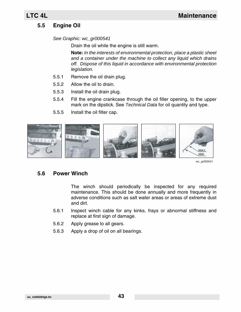
5.5 Engine Oil
See Graphic: wc_gr000541
Drain the oil while the engine is still warm.
Note: In the interests of environmental protection, place a plastic sheetand a container under the machine to collect any liquid which drainsoff. Dispose of this liquid in accordance with environmental protectionlegislation.
5.5.1 Remove the oil drain plug.
5.5.2 Allow the oil to drain.
5.5.3 Install the oil drain plug.
5.5.4 Fill the engine crankcase through the oil filler opening, to the uppermark on the dipstick. See Technical Data for oil quantity and type.
5.5.5 Install the oil filter cap.
5.6 Power Winch
The winch should periodically be inspected for any requiredmaintenance. This should be done annually and more frequently inadverse conditions such as salt water areas or areas of extreme dustand dirt.
5.6.1 Inspect winch cable for any kinks, frays or abnormal stiffness andreplace at first sign of damage.
5.6.2 Apply grease to all gears.
5.6.3 Apply a drop of oil on all bearings.
wc_gr000541
wc_tx000293gb.fm 43

Maintenance LTC 4L
5.7 Engine Maintenance
Beforeeachuse
Every125
hours
Every250
hours
Every500
hours
Every1000 hours
or two years
Check for fluid leaks. •
Check engine oil. •
Check fuel level. •
Replace air filter if indicator light is on.** •
Change engine oil.* •
Check level of battery electrolyte. •
Check condition and tension on fan belt. •
Check condition of radiator hoses. •
Replace oil filter.* •
Replace fuel filter. •
Flush radiator. •
Replace fan belt. •
Check valve clearance. •
Remove sediment in fuel tank. •
Change radiator coolant. •
Replace battery. •
Replace radiator hoses and clamps. •
Replace fuel pipes and clamps. •
* Change engine oil and filter after first 50 hours of operation.** Replace air filter after air filter restriction switch indication or one year. Lombardini does not recommend
the removal of air filter elements for purposes of inspection.
wc_tx000293gb.fm 44
LTC 4L Maintenance
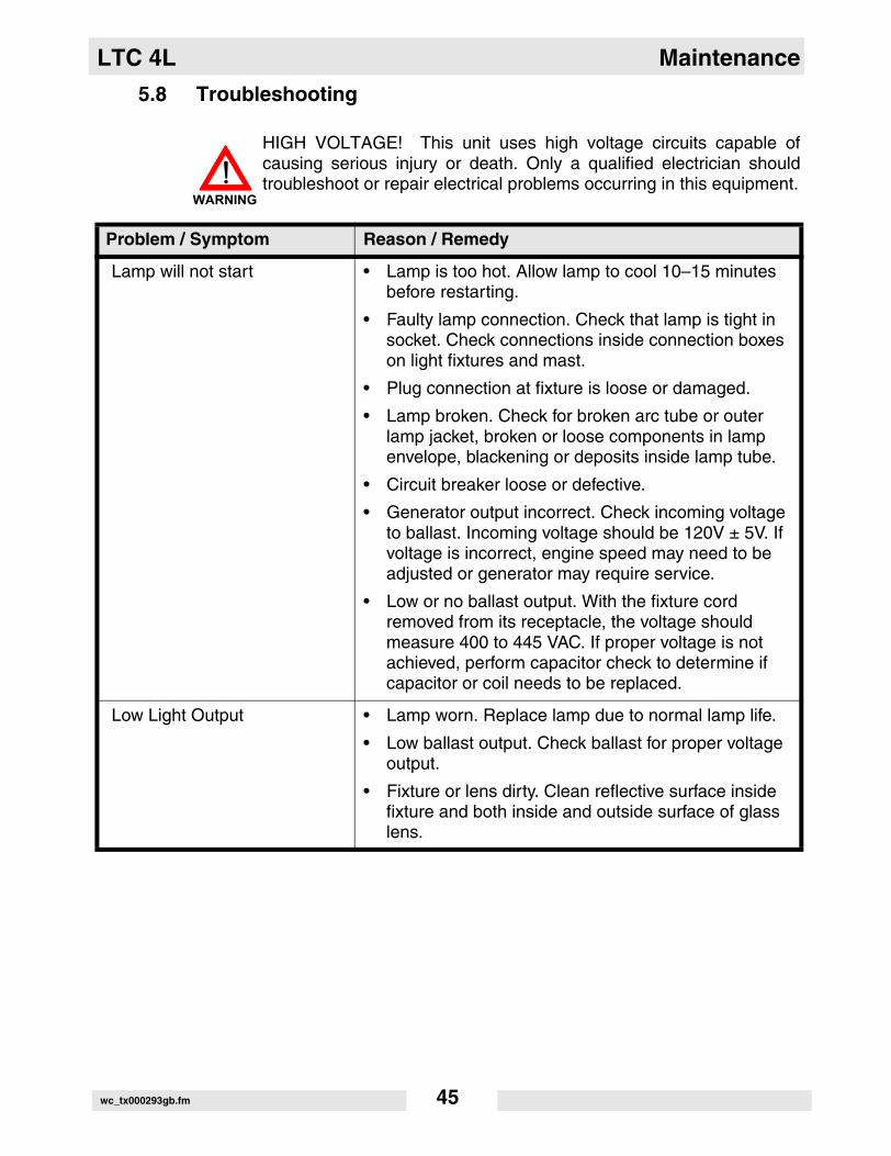
5.8 Troubleshooting
HIGH VOLTAGE! This unit uses high voltage circuits capable ofcausing serious injury or death. Only a qualified electrician shouldtroubleshoot or repair electrical problems occurring in this equipment.
Problem / Symptom Reason / Remedy
Lamp will not start • Lamp is too hot. Allow lamp to cool 10–15 minutes before restarting.
• Faulty lamp connection. Check that lamp is tight in socket. Check connections inside connection boxes on light fixtures and mast.
• Plug connection at fixture is loose or damaged.
• Lamp broken. Check for broken arc tube or outer lamp jacket, broken or loose components in lamp envelope, blackening or deposits inside lamp tube.
• Circuit breaker loose or defective.
• Generator output incorrect. Check incoming voltage to ballast. Incoming voltage should be 120V ± 5V. If voltage is incorrect, engine speed may need to be adjusted or generator may require service.
• Low or no ballast output. With the fixture cord removed from its receptacle, the voltage should measure 400 to 445 VAC. If proper voltage is not achieved, perform capacitor check to determine if capacitor or coil needs to be replaced.
Low Light Output • Lamp worn. Replace lamp due to normal lamp life.
• Low ballast output. Check ballast for proper voltage output.
• Fixture or lens dirty. Clean reflective surface inside fixture and both inside and outside surface of glass lens.
WARNING
wc_tx000293gb.fm 45

Maintenance LTC 4L
5.9 Schematic for 60Hz Metal Halide 4-Light Units (0009375 Rev.105 and higher, 0620018 Rev. 102 and higher )
wc_tx000293gb.fm 46

LTC 4L Maintenance
Ref. Description Ref. Description
a Generator i Engine
b 20 Amp GFI outlet j Capacitor-generator
c Control box - lights k Hour meter
d Floodlights l Transformer
e Terminal Strip m Capacitor
f 20 Amp circuit breaker n Ballasts
g 15 Amp circuit breaker p 25 Amp 2-pole circuit breaker
h Battery
Wire Colors
B Black R Red Y Yellow Or Orange
G Green T Tan Br Brown Pr Purple
L Blue V Violet Cl Clear Sh Shield
P Pink W White Gr Gray LL Light blue
wc_tx000293gb.fm 47
Maintenance LTC 4L
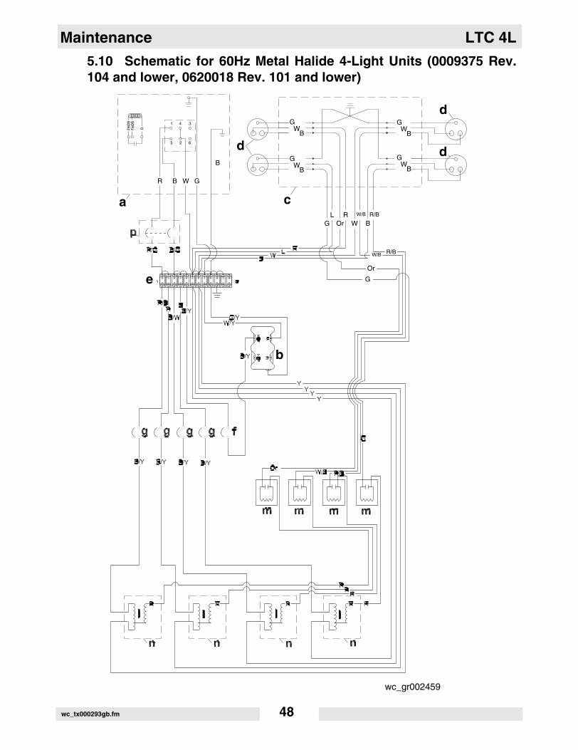
5.10 Schematic for 60Hz Metal Halide 4-Light Units (0009375 Rev.104 and lower, 0620018 Rev. 101 and lower)
BW
G
BW
G
BW
G
BW
G
GL
OrR
WW/B
B
B
a c
d
b
e
1
5
50Hz 0
60Hz
2 6
4 3
WR G
R/B
R/BW/B
Or
G
B
d
d
wc_gr002459
wc_tx000293gb.fm 48
LTC 4L Maintenance
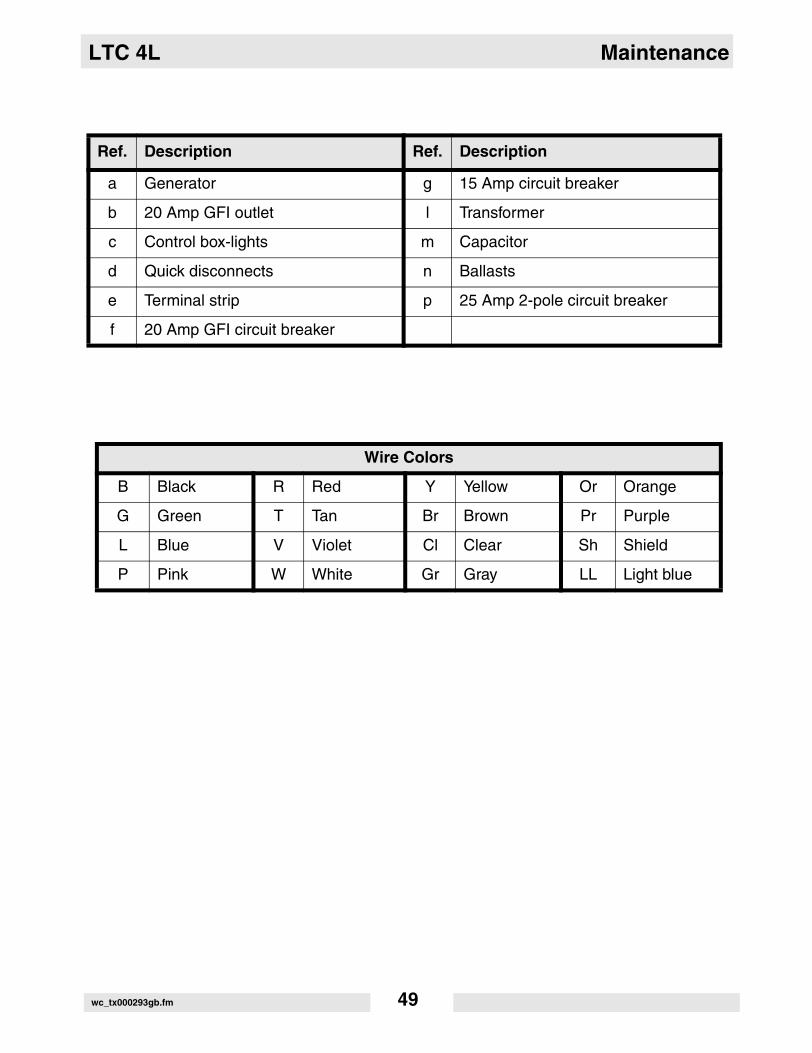
Ref. Description Ref. Description
a Generator g 15 Amp circuit breaker
b 20 Amp GFI outlet l Transformer
c Control box-lights m Capacitor
d Quick disconnects n Ballasts
e Terminal strip p 25 Amp 2-pole circuit breaker
f 20 Amp GFI circuit breaker
Wire Colors
B Black R Red Y Yellow Or Orange
G Green T Tan Br Brown Pr Purple
L Blue V Violet Cl Clear Sh Shield
P Pink W White Gr Gray LL Light blue
wc_tx000293gb.fm 49

Maintenance LTC 4L
5.11 Schematic for 50Hz Metal Halide Units (0009377 Rev. 103 andhigher)
wc_gr003101
-
b
n n
ll
n n
ll
g g g g f
k
m m
WB
LR
R/B
R Br
Br/W
Br/Y
YB/Y
G/Y
Br/Y
Y
L
L
YY
Y
Pr Pr Pr Pr
Pr Pr Pr Pr
YYY Y
OrW/B R/B
G
RR
RR
R
RRRRRR
a
1
5
50Hz 0
60Hz
2 6
4 3
LBr G/Y
B
R/Gr
G/YG/Y
LL
e
h
j
BW
G
BW
G
BW
G
BW
G
GL
OrR
WW/B
B
c
d
R/B
R/BW/B
Or
GGG
d
d
wc_tx000293gb.fm 50
LTC 4L Maintenance
e
Ref. Description Ref. Description
a Generator h To engine control panel
b Main circuit breaker, 25A i Earth-leakage circuit breaker(if equipped)
c Light control box j Receptacle, 230V
d Quick-disconnect plugs k Hour meter
e Terminal strip l Transformer
f Circuit breaker, 20A m Control panel capacitor
g Circuit breaker, 15A n Ballast
Wire Colors
B Black R Red Y Yellow Or Orange
G Green T Tan Br Brown Pr Purple
L Blue V Violet Cl Clear Sh Shield
P Pink W White Gr Gray LL Light blue
wc_tx000293gb.fm 51
Maintenance LTC 4L
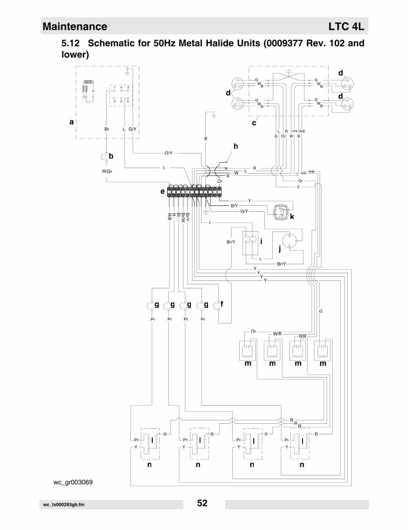
5.12 Schematic for 50Hz Metal Halide Units (0009377 Rev. 102 andlower)
wc_gr003069
-
b
n n
ll
n n
ll
g g g g f
k
m m
WB
LR
R/B
R Br
Br/W
Br/Y
YB/Y
G/Y
Br/Y
Br/YY
L
L
YY
Y
Pr Pr Pr Pr
Pr Pr Pr Pr
YYY Y
OrW/B R/B
G
RR
RR
R
RRRRRR
a
1
5
50Hz 0
60Hz
2 6
4 3
LBr G/Y
B
R/Gr
G/YG/Y
LL
e
h
ij
BW
G
BW
G
BW
G
BW
G
GL
OrR
WW/B
B
c
d
R/B
R/BW/B
Or
GGG
d
d
wc_tx000293gb.fm 52
LTC 4L Maintenance
e
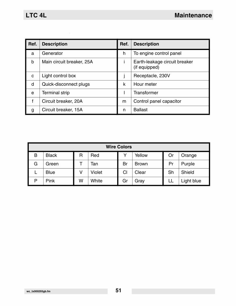
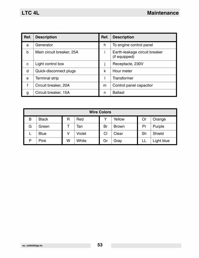
Ref. Description Ref. Description
a Generator h To engine control panel
b Main circuit breaker, 25A i Earth-leakage circuit breaker(if equipped)
c Light control box j Receptacle, 230V
d Quick-disconnect plugs k Hour meter
e Terminal strip l Transformer
f Circuit breaker, 20A m Control panel capacitor
g Circuit breaker, 15A n Ballast
Wire Colors
B Black R Red Y Yellow Or Orange
G Green T Tan Br Brown Pr Purple
L Blue V Violet Cl Clear Sh Shield
P Pink W White Gr Gray LL Light blue
wc_tx000293gb.fm 53

Maintenance LTC 4L
5.13 Generator Capacitor Excitation Schematic 60Hz (0009375 Rev.104 and lower, 0620018 Rev. 101 and lower)
Ref. Description Ref. Description
1 Rotor 4 Capacitor
2 Stator 5 Generator/Terminal block
3 Excitation coils 6 Control box-lights
wc_gr000932
T1
T2
T3
T4
T5
T6
50 Hz60 Hz
Y
120V
240V
120V
L
L2
W
B
6
R
N
43
5
1
12
2
0
C1C1
+
+
wc_tx000293gb.fm 54

LTC 4L Maintenance
5.14 Generator Capacitor Excitation Schematic 50Hz
Ref. Description Ref. Description
1 Rotor 4 Capacitor
2 Stator 5 Generator/Terminal block
3 Excitation coils 6 Control box-lights
wc_gr003076
T1
T2
T3
T4
T5
T6
60 Hz50 Hz
Y
230V
L1
L2L
6
Br
43
5
1
12
2
0
C1C1
_
+_
+
wc_tx000293gb.fm 55

Maintenance LTC 4L
5.15 Trailer Wiring
Ref. Description Ref. Description
a Right stop, turn and tail light d Side light, red
b Left stop, turn and tail light e License plate light
c Side light, amber
Wire Colors
G Green Right stop and turn light
Y Yellow Left stop and turn light
Br Brown License plate, tail and side light
W White Ground
wc_tx000293gb.fm 56
LTC 4L Maintenance
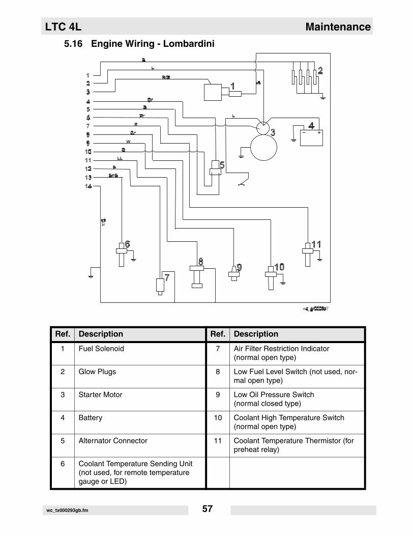
5.16 Engine Wiring - Lombardini
Ref. Description Ref. Description
1 Fuel Solenoid 7 Air Filter Restriction Indicator (normal open type)
2 Glow Plugs 8 Low Fuel Level Switch (not used, nor-mal open type)
3 Starter Motor 9 Low Oil Pressure Switch (normal closed type)
4 Battery 10 Coolant High Temperature Switch (normal open type)
5 Alternator Connector 11 Coolant Temperature Thermistor (for preheat relay)
6 Coolant Temperature Sending Unit (not used, for remote temperature gauge or LED)
wc_tx000293gb.fm 57
Maintenance LTC 4L
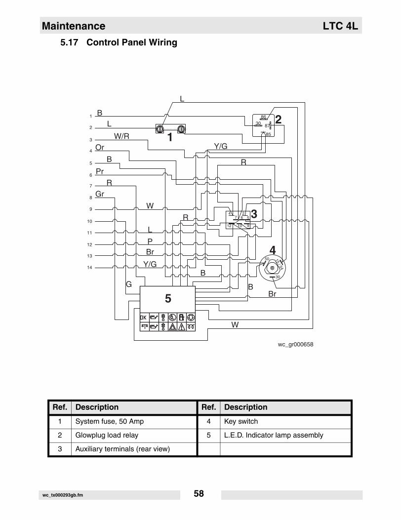
5.17 Control Panel Wiring
Ref. Description Ref. Description
1 System fuse, 50 Amp 4 Key switch
2 Glowplug load relay 5 L.E.D. Indicator lamp assembly
3 Auxiliary terminals (rear view)
L
BL
W/ROr
B
PrR
Gr
W
L
PBr
Y/G
GB
W
BBr
Y/G
R
R
86
85
30 87
4 27 6 5
12 10 9
50
30
15 / 54
wc_gr000658
1
2
5
3
4
1
2
3
4
5
6
7
8
9
10
11
12
13
14
wc_tx000293gb.fm 58

LTC 4L Maintenance
5.18 Power Winch Schematic
Ref. Description Ref. Description
a Vertical winch d Vertical rotary switch
b Telescope winch e Telescope rotary switch
c Fuse / breaker f Starter
wc_tx000293gb.fm 59

Maintenance LTC 4L
Notes:wc_tx000293gb.fm 60


Wacker Construction Equipment AG · Preußenstraße 41 · D-80809 München · Tel.: +49-(0)89-3 54 02 - 0 · Fax: +49 - (0)89-3 54 02-3 90Wacker Corporation · P.O. Box 9007 · Menomonee Falls, WI 53052-9007 · Tel. : (262) 255-0500 · Fax: (262) 255-0550 · Tel. : (800) 770-0957Wacker Asia Pacific Operations · Skyline Tower, Suite 2303, 23/F · 39 Wang Kwong Road, Kowloon Bay, Hong Kong · Tel. +852 2406 60 32 · Fax: +852 2406 60 21