g 100 g 120 - wacker neusonproducts.wackerneuson.com/manuals/operators/0171952en_002.pdf · 1.3...
TRANSCRIPT

Mobile Generator
G 100G 120
OPERATOR’S MANUAL
0171952en 002
0709
0 1 7 1 9 5 2 E N


G 100 / G 120 Foreword
wc_tx000994gb.fm 3
Foreword
Machine Documentation
Keep a copy of the Operator’s Manual with the machine at all times. Use the separate Parts Book supplied with the machine to order replacement parts. If you are missing either of these documents, please contact Wacker Neuson Corporation to order a replacement or visit www.wackerneuson.com. Contact Wacker Neuson Product Support for information on servicing and repairing the machine.When ordering parts or requesting service information, be prepared to provide the machine model number, item number, revision number, and serial number.
Expectations for information in this manual
This manual provides information and procedures to safely operate and maintain the above Wacker Neuson model(s). For your own safety and to reduce the risk of injury, carefully read, understand, and observe all instructions described in this manual. Wacker Neuson Corporation expressly reserves the right to make technical modifications, even without notice, which improve the performance or safety standards of its machines.The information contained in this manual is based on machines manufactured up until the time of publication. Wacker Neuson Corporation reserves the right to change any portion of this information without notice.
Copyright notice
All rights, especially copying and distribution rights, are reserved.Copyright 2009 by Wacker Neuson Corporation.This publication may be reproduced through photocopying by the original purchaser of the machine. Any other type of reproduction is prohibited without express written permission from Wacker Neuson Corporation.Any type of reproduction or distribution not authorized by Wacker Neuson Corporation represents an infringement of valid copyrights, and violators will be prosecuted.
CALIFORNIA Proposition 65 Warning:
Diesel engine exhaust, some of its constituents, and certain vehicle components, contain or emit chemicals known to the State of California to cause cancer and birth defects or other reproductive harm.
Laws pertaining to spark arresters
NOTICE: State Health Safety Codes and Public Resources Codes specify that in certain locations spark arresters be used on internal combustion engines that use hydrocarbon fuels. A spark arrester is a device designed to prevent accidental discharge of sparks or flames from the engine exhaust. Spark arresters are qualified and rated by the United States Forest Service for this purpose. In order to comply with local laws regarding spark arresters, consult the engine distributor or the local Health and Safety Administrator.
Trademarks All trademarks referenced in this manual are the property of their respective owners.

G 100 / G 120 Table of Contents
wc_bo0171947fr_002TOC.fm 4

Table of Contents G 100 / G 120
Foreword 3
1 Safety Information 7
1.1 Signal Words Found in this Manual .......................................................71.2 Safety Guidelines for Operating the Machine ........................................81.3 Operator Safety While Using Internal Combustion Engines ..................91.4 Towing Safety ......................................................................................101.5 Guidelines for Service Safety ..............................................................101.6 Label Locations ...................................................................................121.7 Safety and Warning Labels .................................................................141.8 Informational Labels ............................................................................18
2 Transportation, Lifting, and Storage 22
2.1 Towing .................................................................................................222.2 Lifting ...................................................................................................232.3 Overnight Storage ...............................................................................232.4 Long-Term Storage .............................................................................23
3 Operation 25
3.1 Application ...........................................................................................253.2 Control Panel .......................................................................................263.3 Normal Boot-up Sequence ..................................................................283.4 Generator monitoring ..........................................................................303.5 Engine Monitoring ...............................................................................323.6 Engine Shutdown Faults .....................................................................343.7 Current Overload Fault ........................................................................353.8 Warning Light ......................................................................................363.9 Voltage Selector ..................................................................................373.10 Emergency Stop Switch ......................................................................383.11 Main Line Circuit Breaker ....................................................................393.12 Engine Start Switch .............................................................................403.13 Adjusting Voltage With the Rheostat ...................................................413.14 Connection Lugs .................................................................................423.15 Ground Connection .............................................................................433.16 Convenience Receptacles ...................................................................443.17 Remote Run Terminal Block ...............................................................453.18 Voltage Selector Label ........................................................................463.19 Racor® Crankcase Filter .....................................................................473.20 Before Starting ....................................................................................483.21 Manual Starting ...................................................................................49
wc_bo0171952en_002TOC.fm 5

G 100 / G 120 Table of Contents
3.22 Running the Generator ....................................................................... 513.23 Engine Power Correction Factors ...................................................... 523.24 Stopping the Generator ...................................................................... 533.25 Cold Weather Starting ........................................................................ 533.26 Automatic/Remote Starting ................................................................ 543.27 Remote/Transfer Switch ..................................................................... 554 Maintenance 56
4.1 Periodic Maintenance Schedule ......................................................... 564.2 Breaking In New Machines ................................................................. 574.3 Resetting the Periodic Maintenance Timer ........................................ 574.4 Replacing the Air Filter Element ......................................................... 584.5 Replacing the Racor® Filter Element ................................................. 594.6 Lubricating the Engine ........................................................................ 604.7 Checking the Engine Coolant Level ................................................... 614.8 Maintaining the Trailer ........................................................................ 62
5 Factory-Installed Options 63
5.1 Block Heater ....................................................................................... 635.2 LCD Strip Heater ................................................................................ 645.3 Low Coolant Shutdown ...................................................................... 655.4 Lube Level Maintainer ........................................................................ 665.5 Temperature-Activated Shutters ........................................................ 675.6 Lockable Battery Disconnect .............................................................. 67
6 Schematics 68
6.1 DC Schematic .................................................................................... 686.2 DC Schematic Components ............................................................... 696.3 AC Schematic ..................................................................................... 706.4 AC Schematic Components ............................................................... 71
7 Basic Troubleshooting 72
8 Technical Data 73
8.1 Engine ................................................................................................ 738.2 Generator Data ................................................................................... 748.3 Trailer and Skid Data .......................................................................... 758.4 Dimensions ......................................................................................... 76
wc_bo0171952en_002TOC.fm 6
G 100 / G 120 Safety Information
1 Safety Information
1.1 Signal Words Found in this Manual
NOTICE: Used without the safety alert symbol, NOTICE indicates a situation which, if not avoided, could result in property damage.
Note: Contains additional information important to a procedure.
This is the safety alert symbol. It is used to alert you to potential personal hazards.Obey all safety messages that follow this symbol.
DANGERDANGER indicates a hazardous situation which, if not avoided, will result in death or serious injury.
Obey all safety messages that follow this symbol to avoid injury or death.
WARNINGWARNING indicates a hazardous situation which, if not avoided, could result in death or serious injury.
Obey all safety messages that follow this symbol to avoid possible injury or death.
CAUTIONCAUTION indicates a hazardous situation which, if not avoided, could result in minor or moderate injury.
Obey all safety messages that follow this symbol to avoid possible minor or moderate injury.
wc_si000291gb.fm 7

Safety Information G 100 / G 120
1.2 Safety Guidelines for Operating the Machine
Before starting the machine
Before starting this machine:Have a certified electrician set up the generator set. Do not allow untrained personnel to operate or service the generator. Make a walk-around inspection of the generator set before starting it. Open side doors and visually inspect engine compartment for obvious damage or the presence of foreign objects which might affect operation.Follow starting and stopping instructions described in this manual. Know how to operate and stop the generator before starting it.Do not start a machine in need of repair.Make sure the machine is on a firm, level surface and will not tip, roll, slide, or fall while operating.Remove all tools, cords, and other loose items from the generator before starting it.
Electrical safety
To increase electrical safety while operating this machine:Do not operate the generator, or tools attached to the generator, with wet hands.Do not use worn electrical cords. Severe electrical shock and equipment damage may result.Do not operate generator in standing water.Make certain the machine is well-grounded and securely fastened to a good earthen ground per national and local regulations.Do not overload the generator. The total amperage of the tools and equipment attached to the generator must not exceed the load rating of the generator.
WARNINGMachines operated improperly or by untrained personnel can be hazardous.
Read the operating instructions contained in both this Operator’s Manual and the engine operator’s manual.Familiarize yourself with the location and proper use of all controls.Inexperienced operators should receive instruction from someone familiar with the machine before being allowed to operate it.
WARNINGBackfeed from the generator into the public power distribution system can seriously injure or kill utility workers!
Improper connection of generator to a building’s electrical system can allow electrical current from the generator to backfeed into utility lines. This may result in electrocution of utility workers, fire, or explosion. Connections to a building’s electrical system must be made by a qualified electrician and comply with all applicable laws and electrical codes.If connected to a building’s electrical system, the generator must meet the power, voltage, and frequency requirements of the equipment in the building.
wc_si000291gb.fm 8

G 100 / G 120 Safety Information
Operating safetyTo increase operating safety while running this machine:Do not operate the generator when open containers of fuel, paint, or other flammable liquids are in the vicinity of the generator.Do not place flammable material or liquids near the generator.Do not operate the machine indoors unless exhaust fumes can be adequately ventilated.Do not touch the hot engine, exhaust, or generator components. Burns will result.Do not use the emergency stop button except in case of an actual emergency. Do not restart the engine until the cause of the trouble has been determined and fixed.
Always do the following:Wear hearing protection when operating equipment.Keep the machine at least one meter (three feet) away from structures, buildings, and other equipment during use.Keep the area immediately surrounding and underneath the machine clean, neat, and free of debris and combustible materials. Make sure that the area overhead is clear of debris that could fall onto or into the machine or exhaust compartment.
Storing the machine
Store the machine properly when it is not being used. The machine should be stored in a clean, dry location out of the reach of children.
1.3 Operator Safety While Using Internal Combustion Engines
1. Do not run engine indoors or in an area with poor ventilation unless exhaust hoses are used.
2. Do not fill or drain the fuel tank near an open flame, while smoking, or while the engine is running.
3. Do not refuel a hot or running engine.4. Refill the fuel tank in a well-ventilated area.5. Do not touch or lean against hot exhaust pipes.6. Replace the fuel tank cap after refueling.7. Do not start the engine if fuel has spilled or a fuel odor is present. Move the gen-
erator away from the spill and wipe the generator dry before starting.8. Do not remove the radiator cap when the engine is running or hot. The radiator
fluid is hot and under pressure and may cause severe burns!
WARNINGInternal combustion engines present special hazards during operation and fueling. Failure to follow the warnings and safety standards could result in severe injury or death.
Read and follow the warning instructions in the engine owner’s manual and the safety guidelines below.
wc_si000291gb.fm 9

Safety Information G 100 / G 120
1.4 Towing Safety
Hitch and coupling
Before towing, follow the instructions below to ensure that the hitch and coupling are ready for use.
Check that the hitch and coupling on the vehicle are rated equal to, or greater than, the trailer's Gross Vehicle Weight Rating (GVWR).Inspect the hitch and coupling for wear or damage. DO NOT tow the trailer using defective parts.Make sure the coupling is securely fastened to the vehicle.Connect the safety chains.Connect the breakaway cable safety hook to the bumper or rear of the vehicle. Do not attach to the vehicle hitch.
Tires and wheels
Before towing, follow the instructions below to ensure that the tires and wheels are ready for use.
Check the tires on the trailer for tread wear, inflation, and condition. Replace worn tires. Check that the lug nuts holding the wheels are tight and that none are missing.
Brakes and lights
Before towing, follow the instructions below to ensure that the brakes and lights are ready for use.
Test the surge brakes on the trailer. Test the brakes on the vehicle that will be used for towing.Make sure directional and trailer lights are connected and working properly.
1.5 Guidelines for Service Safety
Prerequisites Before servicing this machine:Stop the engine.If the engine has an electric starter, isconnect the negative terminal on the battery.Attach a “DO NOT START” sign to the machine. This will notify everyone that the machine is being serviced and will reduce the chance of someone inadvertently trying to start the machine.
WARNINGTowing a large trailer requires special care. To reduce the possibility of an accident:
Both the trailer and vehicle must be in good condition.The trailer and the vehicle must be securely fastened to each other.
WARNINGA poorly maintained machine can be a personal injury hazard.
Follow the Periodic Maintenance schedule in this Operator’s Manual.Repair or replace any damaged or defective components immediately.
wc_si000291gb.fm 10

G 100 / G 120 Safety Information
Ground connection
The generator must be connected to a good earthen ground for proper operating safety!Ground the generator in accordance with the standards defined in national, state, and local regulations.
Personal injury avoidance
Let the engine and muffler cool before transporting or servicing the machine.Do not service the machine if your clothing or skin is wet.Do not allow untrained personnel to service this machine. Only trained electrical technicians should be allowed to service the electrical components of this machine.
Service safety Do not modify the machine without the express written approval of the manufacturer.Do not allow water to accumulate around the base of the machine. If water is present, move the machine and allow the machine to dry before servicing.When cleaning the unit, do not pressure wash the control panel or any other electrical components.
..
Replacing parts and labels
Replace worn or damaged components.Use only spare parts recommended by Wacker Neuson.Keep the fuel lines in serviceable condition. Leaking fuel and flames are extremely explosive!Replace all missing and hard-to-read labels. Labels provide important operating instructions and warn of dangers and hazards.Check all external fasteners at regular intervals.
wc_si000291gb.fm 11
Safety Information G 100 / G 120
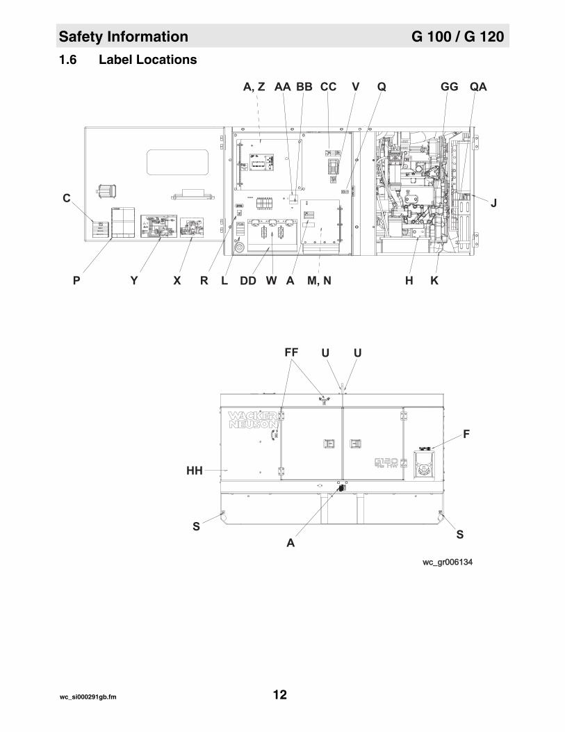
1.6 Label Locations
AA BBA, Z Q
YP
C
X AL WDD M, NR H K
J
wc_gr006134wc_gr006134
SS
HH
A
F
UUFF
QAGGVCC
DIESEL
STOP
PELIGRODANGER
GEFAHRDANGER
WARNING
WARNUNG
Lock doors. Access can cause electric shock or injury. Arc flash hazard!
Turen schliessen! Zugang kann elektrischen Schlag oder Verletzung verursachen. Gefahr: Kurzschlusslichtbogen!
Fermer les portes d'acces ou il pourrait en resulter risque d'electrocution ou accidents de personne. Danger: Arco de court-circuit!
AVERTISSEMENT
ADVERTENCIACierre las puertas. Ya que de orto modo existe el peligro de una descarga electrica o de lesiones personales. Peligro: Arco voltaico de cortocircuito!
wc_si000291gb.fm 12
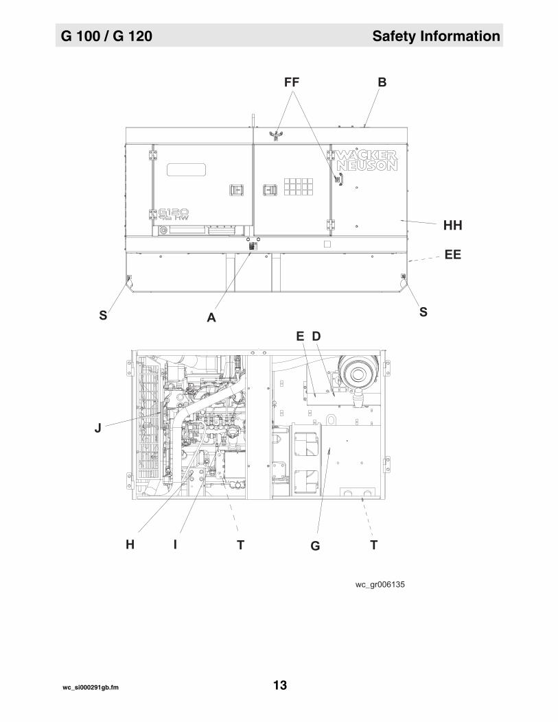
G 100 / G 120 Safety Information
wc_gr006135
GI
J
SS A
H
FF B
EE
TT
DE
WARNINGWARNING
WARNUNGWARNUNG
Lock doors. Access can cause electric shock or injury. Lock doors. Access can cause electric shock or injury. Arc flash hazard!Arc flash hazard!
AVERTISSEMENTAVERTISSEMENTFermer les portes d'acces ou il pourrait en resulter Fermer les portes d'acces ou il pourrait en resulter risque d'electrocution ou accidents de personne. risque d'electrocution ou accidents de personne. Danger: Arco de court-circuit!Danger: Arco de court-circuit!
Cierre las puertas. Ya que de orto modo existe el peligro Cierre las puertas. Ya que de orto modo existe el peligro de una descarga electrica o de lesiones personales. de una descarga electrica o de lesiones personales. Peligro: Arco voltaico de cortocircuito! Peligro: Arco voltaico de cortocircuito!
ADVERTENCIAADVERTENCIA
Turen schliessen! Zugang kann elektrischen Schlag oder Turen schliessen! Zugang kann elektrischen Schlag oder Verletzung verursachen. Gefahr: Kurzschlusslichtbogen! Verletzung verursachen. Gefahr: Kurzschlusslichtbogen!
HH
wc_si000291gb.fm 13

Safety Information G 100 / G 120
1.7 Safety and Warning Labels
Ref. Label Definition
A WARNING! Lock doors. Access can cause electric shock, arc flash, or injury.
B WARNING! Pressurized contents. Do not open when hot!
C WARNING!Read and understand the supplied Operator’s Manual before operating the machine. Failure to do so increases the risk of injury to yourself or others.
D NOTICE Never change switch position with engine running. Results in damage to machine.
E WARNING! Electric shock and arc flash can cause serious injury or death.
wc_si000291gb.fm 14

G 100 / G 120 Safety Information
F DANGER! Asphyxiation hazard. Read the Operator’s Manual for instructions. No sparks, flames, or burning objects near machine. Stop the engine before adding fuel. Use only diesel fuel.
G WARNING! To prevent hearing loss, wear hearing protection.Hand injury if entangled in moving belt.Rotating machinery! Do not reach inside with engine running.WARNING! Hot surface!NOTICEAvoid spraying water into generator.
H WARNING! Hot surface!
I WARNING! Hot surface!
J WARNING!To prevent hearing loss, wear hearing protection when operating the machine.WARNING! Pressurized contents. Do not open when hot!WARNING! Hand injury if entangled in moving belt.WARNING! Rotating machinery! Do not reach inside machine with engine running.
Ref. Label Definition
wc_si000291gb.fm 15
Safety Information G 100 / G 120
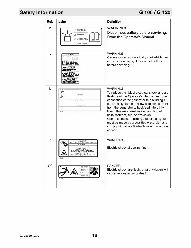
K WARNING! Disconnect battery before servicing.Read the Operator’s Manual.
L WARNING! Generator can automatically start which can cause serious injury. Disconnect battery before servicing.
M WARNING! To reduce the risk of electrical shock and arc flash, read the Operator’s Manual. Improper connection of the generator to a building’s electrical system can allow electrical current from the generator to backfeed into utility lines. This may result in electrocution of utility workers, fire, or explosion. Connections to a building’s electrical system must be made by a qualified electrician and comply with all applicable laws and electrical codes.
Z WARNING!
Electric shock at cooling fins.
CC DANGER Electric shock, arc flash, or asphyxiation will cause serious injury or death.
Ref. Label Definition
wc_si000291gb.fm 16

G 100 / G 120 Safety Information
GG WARNING!To prevent hearing loss, wear hearing protection when operating the machine.WARNING! Hand injury if entangled in moving belt.WARNING! Rotating machinery! Do not reach inside machine with engine running.
Ref. Label Definition
179282
WARNUNG
WARNING
ADVERTENCIA
AVERTISSEMENT
wc_si000291gb.fm 17

Safety Information G 100 / G 120
1.8 Informational Labels
Ref. Label Definition
N Voltage selector label
P
G 240G 150 / G180
= 40Nm (29.5 Ft Lbs)
L3-N = 277V
L1-L2= 480V
L2-N = 277V
L1-N = 277V
L3-L1= 480V
L2-L3= 480V
L11
2
N4
3
8
L-L
12
56
L-N
L210L39
711
L-LL2-N = 120V
L1-L2= 208V
L3-N = 120V
L1-N = 120V
L2 L3-L1= 208V
L2-L3= 208V5
2
6
1
N
4
12
3
11
L1
9L3
10 8
7
L-N
wc_si000291gb.fm 18

G 100 / G 120 Safety Information
Q
QA
Operator’s Manual must be stored on machine. Replacement Operator’s Manual can be ordered through your local Wacker Neuson distributor.
R Remote start operation. Read Operator’s Manual for instructions.
S Tie-down point.
T Electrical ground
U NOTICE Lifting point.
V Operating the main circuit breaker supplies or interrupts power to the customer connection lugs.
W Neutral bonded to frame
Ref. Label Definition
wc_si000291gb.fm 19

Safety Information G 100 / G 120
X Engine wiring
Y Generator and Receptacle Wiring
AA A nameplate listing the model number, item number, revision number, and serial number is attached to each unit. Please record the information found on this plate so it will be available should the nameplate become lost or damaged. When ordering parts or requesting service information, you will always be asked to specify the model number, item number, revision number, and serial number of the unit.
BB This machine may be covered by one or more patents.
DD NOTICEReceptacles not used when:Selector switch set to 208/120V and voltage greater than 228V.Selector switch set to 480/277V and voltage greater than 457V.
Ref. Label Definition
UTILITY 159116UTILITY 159116
U.S.PAT.Nos.: 6012285, 6471476, U.S.PAT.Nos.: 6012285, 6471476, D416858, D454357 OTHER U.S. AND D416858, D454357 OTHER U.S. AND FOREIGN PATENTS PENDINGFOREIGN PATENTS PENDING
wc_si000291gb.fm 20
G 100 / G 120 Safety Information
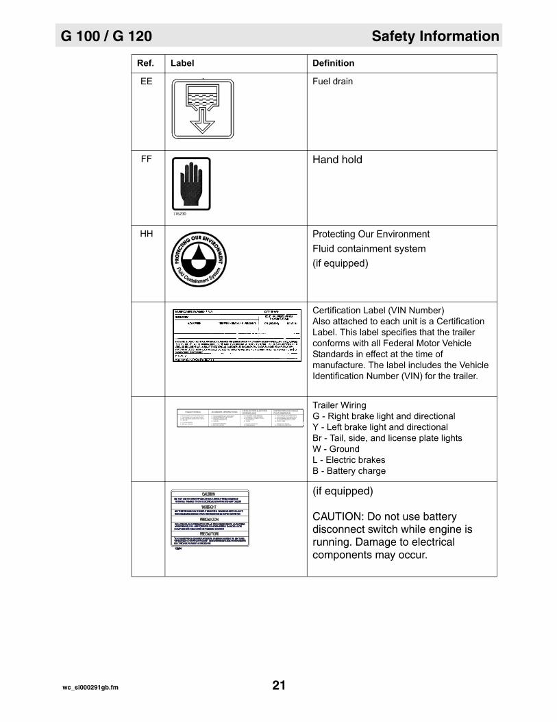
EE Fuel drain
FF Hand hold
HH Protecting Our EnvironmentFluid containment system(if equipped)
Certification Label (VIN Number)Also attached to each unit is a Certification Label. This label specifies that the trailer conforms with all Federal Motor Vehicle Standards in effect at the time of manufacture. The label includes the Vehicle Identification Number (VIN) for the trailer.
Trailer WiringG - Right brake light and directionalY - Left brake light and directionalBr - Tail, side, and license plate lightsW - Ground L - Electric brakesB - Battery charge
(if equipped)
CAUTION: Do not use battery disconnect switch while engine is running. Damage to electrical components may occur.
Ref. Label Definition
wc_si000291gb.fm 21
Transportation, Lifting, and Storage G 100 / G 120
2 Transportation, Lifting, and Storage
2.1 Towing
Provided equipment
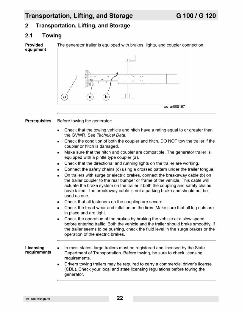
The generator trailer is equipped with brakes, lights, and coupler connection.
Prerequisites Before towing the generator:
Check that the towing vehicle and hitch have a rating equal to or greater than the GVWR. See Technical Data.Check the condition of both the coupler and hitch. DO NOT tow the trailer if the coupler or hitch is damaged.Make sure that the hitch and coupler are compatible. The generator trailer is equipped with a pintle type coupler (a).Check that the directional and running lights on the trailer are working.Connect the safety chains (c) using a crossed pattern under the trailer tongue.On trailers with surge or electric brakes, connect the breakaway cable (b) on the trailer coupler to the rear bumper or frame of the vehicle. This cable will actuate the brake system on the trailer if both the coupling and safety chains have failed. The breakaway cable is not a parking brake and should not be used as one.Check that all fasteners on the coupling are secure.Check the tread wear and inflation on the tires. Make sure that all lug nuts are in place and are tight.Check the operation of the brakes by braking the vehicle at a slow speed before entering traffic. Both the vehicle and the trailer should brake smoothly. If the trailer seems to be pushing, check the fluid level in the surge brakes or the operation of the electric brakes.
Licensing requirements
In most states, large trailers must be registered and licensed by the State Department of Transportation. Before towing, be sure to check licensing requirements.Drivers towing trailers may be required to carry a commercial driver’s license (CDL). Check your local and state licensing regulations before towing the generator.
wc gr005197
a c b
wc_tx001191gb.fm 22

G 100 / G 120 Transportation, Lifting, and Storage
Coupler maintenanceA film of grease on the coupler will extend coupler life and eliminate squeaking. Wipe the coupler clean and apply fresh grease each time the trailer is towed.
Towing safety When towing, maintain extra space between vehicles and avoid soft shoulders, curbs and sudden lane changes. If you have not pulled a trailer before, practice turning, stopping, and backing up in an area away from heavy traffic.Do not exceed 55 mph when towing a trailer.
2.2 Lifting
Prerequisites Before lifting the generator:
refer to the Technical Data section for the proper operating weight of the generatormake sure the lifting devices have sufficient capacity to lift the machine safelymake sure the winch or crane to be used for lifting the machine is in operable condition and designed for such work
Lifting the generator
A central lifting eye is located at the top of the generator and is attached to a lifting frame inside the housing.
When lifting the generator, attach a hook or sling securely to the lifting eye.
2.3 Overnight Storage
When storing the generator overnight, make sure all access doors are closed and padlocked.
Do not store the generator overnight in a low lying area that might fill with water during a heavy storm.
2.4 Long-Term Storage
If the generator is being stored for several months, follow the engine manufacturer’s recommendations for long-term storage. These procedures are designed to help minimize engine corrosion.
wc_tx001191gb.fm 23

Transportation, Lifting, and Storage G 100 / G 120
Notes:wc_tx001191gb.fm 24
G 100 / G 120 Operation
3 Operation
3.1 Application
Generator application
This machine is a heavy-duty sound-attenuated generator designed to provide single and three-phase power for construction, commercial, and industrial applications where reliable power is needed..
Safety notices Do not exceed the power output of the generator. Damage to tools or generator will occur. Refer to Technical Data.When using the generator as a standby or substitute power supply, make sure the voltage and phase rotation of the line connections match those of the utility lines. Failure to match phase rotation and voltage may cause equipment connected to the generator to operate incorrectly! This could create unsafe operating conditions.Do not exceed the rated current limit of any receptacle.The bonding bar between the ground connections must remain in place at all times unless a qualified electrician determines otherwise.
wc_tx000995gb.fm 25
Operation G 100 / G 120
3.2 Control Panel
wc_gr006136
m n ud s
e a
b
f h
c
g
j
o
l
k
p
q
r
v
wc_tx000995gb.fm 26

G 100 / G 120 Operation
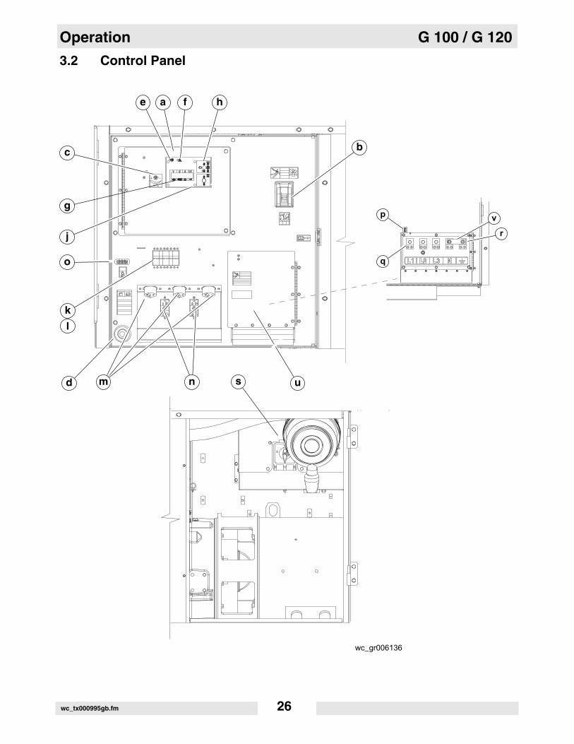
Ref. Description Ref. Descriptiona Control panel access door m Twist-lock receptacle (120/240 VAC,
50 Amp) - threeb Main circuit breaker n GFI receptacle (120 VAC, 20 Amp)
- two
c Voltage adjustment rheostat o Remote run terminal blockd Emergency stop p Interlock switche Shutdown LED q Customer connection terminal lugsf Pre-alarm LED r Ground connectiong LCD panel s Voltage selectorh Engine start switch t Voltage selector access doorj Engine hours switch u Customer connection terminal lugs
access doorl Circuit breaker (120/240V, 50 Amp) -
threev Bonding bar
wc_tx000995gb.fm 27

Operation G 100 / G 120
3.3 Normal Boot-up Sequence
During the boot-up sequence, the ECM scrolls through several screens before it settles into displaying the run screen.
ECM Display Description
Start of the boot-up sequence. The ECM display reads “Initializing” and shows the model of the generator. If the model displayed does not match the model of the generator, call Wacker Neuson Service.
The ECM displays the countdown time until the next scheduled service. The timer starts at 250 and counts down to 0.
The ECM displays this screen to indicate that the intake air is being heated.
The ECM displays this screen to signal that the intake air heating process is complete.
The ECM displays this screen as soon as the engine starts. Note that some of the values such as voltage, may not be up to their running values at this stage of the sequence.
The ECM displays this screen to let the operator know that the Under Frequency Protection system (engine speed) has been enabled.
InitializingG xxx
Time to Service250
Air Intake Heater0 95% 89 13.9
Return to OFF0 95% 89 13.9
80 P2 0 60.071 75% 87 12.7
Under FrequencyProtect Enabled
wc_tx000995gb.fm 28

G 100 / G 120 Operation
At this point in the sequence, the ECM displays running values.
The ECM displays this screen to let the operator know that the engine protection system has been enabled.
The ECM displays the AC configuration as determined by the position of the voltage selector switch (VSS).
The ECM displays this screen to let the operator know that the alternator protection system has been enabled.
The ECM displays the line-to-line voltage. (This screen is shown for 3-phase VSS positions only.)
At this point, the ECM displays the run screen and the values for the main generator variables: voltage, phase* (leg), amperage, Hertz. The ECM will also display the values for the main engine variables: oil pressure, fuel tank quantity, engine temperature, and battery voltage. *Note: The ECM display scrolls through each phase (P1, P2, P3) if in the 3-phase mode, or L1, L3, and L1 + L3 if in the single-phase mode.
ECM Display Description
480 P2 0 60.071 75% 87 12.7
Eng ProtectionEnabled
AC Configuration
Alt ProtectionEnabled
Rated Volts L–L
480 P2 0 60.071 75% 87 12.7
wc_tx000995gb.fm 29

Operation G 100 / G 120
3.4 Generator monitoring
Generator information is displayed on the top line of the LCD panel and is scrolled continuously while the generator is operating, to show the voltage, amperage and frequency of each phase.
Note: To prevent the display from scrolling, press the ENG HRS switch down.
Volts “V”—Displays the AC output voltage being produced by the generator.
Phase “Ø”—Indicates which phase is currently being displayed.
Amps “A”—Displays the AC output amperage produced by the generator. If the generator is operating at no-load, output amperage will display a 0.
Hertz “Hz”—Displays output frequency.
ECM Display Description
Sample display with engine running.
Sample display in “Auto” mode.
208 1 24 6078 85% 175 14.3
UNIT IN AUTO Ø 100% 85 13.2
wc_tx000995gb.fm 30
G 100 / G 120 Operation
Notes:wc_tx000995gb.fm 31

Operation G 100 / G 120
3.5 Engine Monitoring
Description With the engine start switch set to “RUN/START” or “REMOTE START”, engine information will be continuously displayed on the bottom line of the LCD panel.
Indicators
Sample displays
Symbol Meaning Description
OIL Displays engine oil pressure between 0–100 psi.Normal operating pressure = 60–80 psi.Engine shuts down automatically below 15 psi.
FUEL Indicates relative fuel level in the fuel tank.Engine shuts down automatically at 5% level.
TEMPERATURE Displays temperature of engine coolant.Engine shuts down automatically if coolant tem-perature gets too high.
BATTERY Measures engine starting battery voltage.Normal reading is 13.5–14.5V.Check engine charging system if voltage falls sig-nificantly outside this range.Actual battery voltage is displayed when the engine switch is set to REMOTE START and the generator is in standby mode.
ENGINE HOURS
Displays engine running hours, periodic mainte-nance timer, and Engine Diagnostic Trouble Codes when switch is pressed UP.Engine hours accumulate only while engine is actually running.Note: When held down, this switch can be used to lock in a specific display for a single phase.
Display Description
Sample display of engine hours.
Sample display of periodic maintenance timer.
RUNNING HOURS135.2
TIME TO SERVICE180.2 hrs.
wc_tx000995gb.fm 32

G 100 / G 120 Operation
Sample display showing Engine Diagnostic Trouble Codes.SPN = Suspect Parameter NumberFMI = Failure Mode Identifier
Display Description
SPN.FMI 100.01
wc_tx000995gb.fm 33
Operation G 100 / G 120
3.6 Engine Shutdown Faults
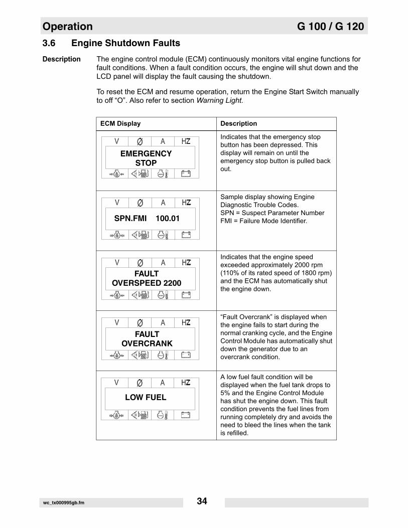
Description The engine control module (ECM) continuously monitors vital engine functions for fault conditions. When a fault condition occurs, the engine will shut down and the LCD panel will display the fault causing the shutdown.
To reset the ECM and resume operation, return the Engine Start Switch manually to off “O”. Also refer to section Warning Light.
ECM Display Description
Indicates that the emergency stop button has been depressed. This display will remain on until the emergency stop button is pulled back out.
Sample display showing Engine Diagnostic Trouble Codes.SPN = Suspect Parameter NumberFMI = Failure Mode Identifier.
Indicates that the engine speed exceeded approximately 2000 rpm (110% of its rated speed of 1800 rpm) and the ECM has automatically shut the engine down.
“Fault Overcrank” is displayed when the engine fails to start during the normal cranking cycle, and the Engine Control Module has automatically shut down the generator due to an overcrank condition.
A low fuel fault condition will be displayed when the fuel tank drops to 5% and the Engine Control Module has shut the engine down. This fault condition prevents the fuel lines from running completely dry and avoids the need to bleed the lines when the tank is refilled.
EMERGENCYSTOP
SPN.FMI 100.01
FAULTOVERSPEED 2200
FAULTOVERCRANK
LOW FUEL
wc_tx000995gb.fm 34
G 100 / G 120 Operation
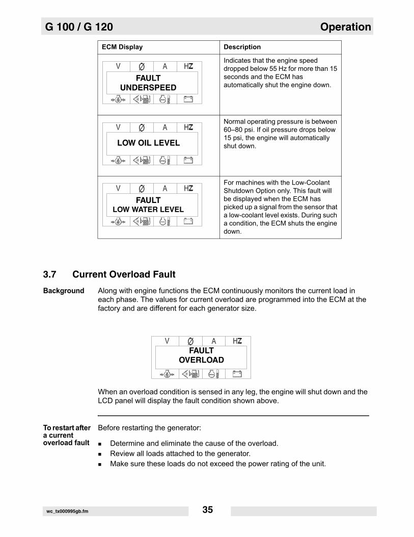
3.7 Current Overload Fault
Background Along with engine functions the ECM continuously monitors the current load in each phase. The values for current overload are programmed into the ECM at the factory and are different for each generator size.
When an overload condition is sensed in any leg, the engine will shut down and the LCD panel will display the fault condition shown above.
To restart after a current overload fault
Before restarting the generator:
Determine and eliminate the cause of the overload.Review all loads attached to the generator.Make sure these loads do not exceed the power rating of the unit.
Indicates that the engine speed dropped below 55 Hz for more than 15 seconds and the ECM has automatically shut the engine down.
Normal operating pressure is between 60–80 psi. If oil pressure drops below 15 psi, the engine will automatically shut down.
For machines with the Low-Coolant Shutdown Option only. This fault will be displayed when the ECM has picked up a signal from the sensor that a low-coolant level exists. During such a condition, the ECM shuts the engine down.
ECM Display Description
FAULTUNDERSPEED
LOW OIL LEVEL
FAULTLOW WATER LEVEL
FAULTOVERLOAD
wc_tx000995gb.fm 35

Operation G 100 / G 120
3.8 Warning Light
Location and description
The amber warning light (d) is located on the metering panel. The light serves as a pre-alarm and turns on prior to a potential engine fault condition. At the same time that the light goes on, the LCD panel will begin blinking to indicate which engine function is approaching its fault value.
Engine pre-alarms
Fuel Level = 15%High Temperature = 226°FLow Oil Pressure = 20 psiTime to Service = 250 hours
wc_gr005201
d
wc_tx000995gb.fm 36

G 100 / G 120 Operation
3.9 Voltage Selector
Location The voltage selector switch is located inside the generator enclosure near the engine air cleaner. To access the switch, open the rear door on the left side of the generator enclosure.
NOTICE: Do not change the voltage selector switch with the engine running. This can cause arcing and can severely damage the switch and the generator windings.
Description The voltage selector mechanically changes the connections between the generator output leads and the terminal lugs on the generator. This allows different voltage ranges to be selected:
Operation Select the voltage range by rotating the handle on the voltage selector switch to the desired voltage.
Locking the voltage selector
The voltage selector is equipped with a locking mechanism. This allows the voltage setting to be locked in place to prevent unauthorized personnel from changing the voltage selection. To lock the voltage selector switch in position, push the locking mechanism up and attach a padlock through the openings in the locking strip.
WARNINGPossibility of electrocution! High voltage is present inside the machine enclosure when the generator is operating!
Never open the access door while the generator is operating.
Available Voltage Ranges
120/240 VAC 1Ø120/208 VAC 3Ø139/240 VAC 3Ø (Refer to section Voltage Adjustment Rheostat.)
277/480 VAC 3Ø
120 / 2083Ø
277 / 4803Ø
120 / 240
wc_gr005686
wc_tx000995gb.fm 37

Operation G 100 / G 120
3.10 Emergency Stop Switch
Location The emergency stop switch is activated by pressing the red button located to the left of the control panel. The button can be accessed with the panel doors closed. It is electrically isolated from the switch and also from the rest of the metering panel.
Operation Activate the emergency stop switch by pressing the red button. Activating the emergency stop switch opens the main circuit breaker and the fuel solenoid, and results in the engine shutting down. The switch will remain activated until the button is pulled out.
NOTICE: Press the emergency stop button only in the case of an actual emergency where the generator must be stopped immediately! In all other instances, open the main line circuit breaker and then turn the engine start switch to off “O”.
EMERGENCY
STOP
wc_gr005202
wc_tx000995gb.fm 38

G 100 / G 120 Operation
3.11 Main Line Circuit Breaker
Location The main line circuit breaker is located on the control panel.
Operation In the “off” position, the main line circuit breaker interrupts power from the selector switch to the terminal lugs at the bottom of the generator panel.
NOTICE: Before shutting down the generator or performing any service to the generator unit, make sure the main line circuit breaker is in the off “O” position.
NOTICE: The convenience receptacles are not connected through the main line circuit breaker. As a result, these receptacles are powered even with the main breaker in the off “O” position.
To turn off power to receptacles, open the individual circuit breakers provided for each.
wc_gr005693
WARNINGPossibility of electrocution! High voltage is present inside the control panel when the generator is operating!
Never open the control panel while the generator is operating.
wc_tx000995gb.fm 39

Operation G 100 / G 120
3.12 Engine Start Switch
Location and description
The engine start switch (e) is located on the right side of the control panel. It is a three-position switch: “REMOTE START,” off “O,” and “START/RUN.”
Operation REMOTE START position:
The REMOTE START position is the normal setting when the generator is being operated as a back-up power supply connected to a remote switch. In the REMOTE START position, the generator is in standby mode and will not start until the remote switch closes.
START/RUN position:
In the START/RUN position, the switch immediately launches the engine start cycle and activates the starter motor to crank the engine.
Off “O” position:
In the off “O” position, power to the engine’s electrical system, including the fuel solenoid, is disconnected.
Note: When set in the REMOTE START or START/RUN position, the engine start switch applies battery power to the control module to turn on the LCD panel, and also energizes the engine’s electrical system.
wc_tx000995gb.fm 40

G 100 / G 120 Operation
3.13 Adjusting Voltage With the Rheostat
Location and description
The voltage adjustment rheostat (f) is located directly to the left of the metering panel. Use the rheostat to adjust the AC voltage output.
Operation To adjust the AC voltage output:
Loosen the locking nut.Turn the adjusting screw clockwise to increase the voltage output.Turn the adjusting screw counterclockwise to decrease the voltage output.Monitor the voltage at the LCD panel.
f
wc_tx000995gb.fm 41
Operation G 100 / G 120
3.14 Connection Lugs
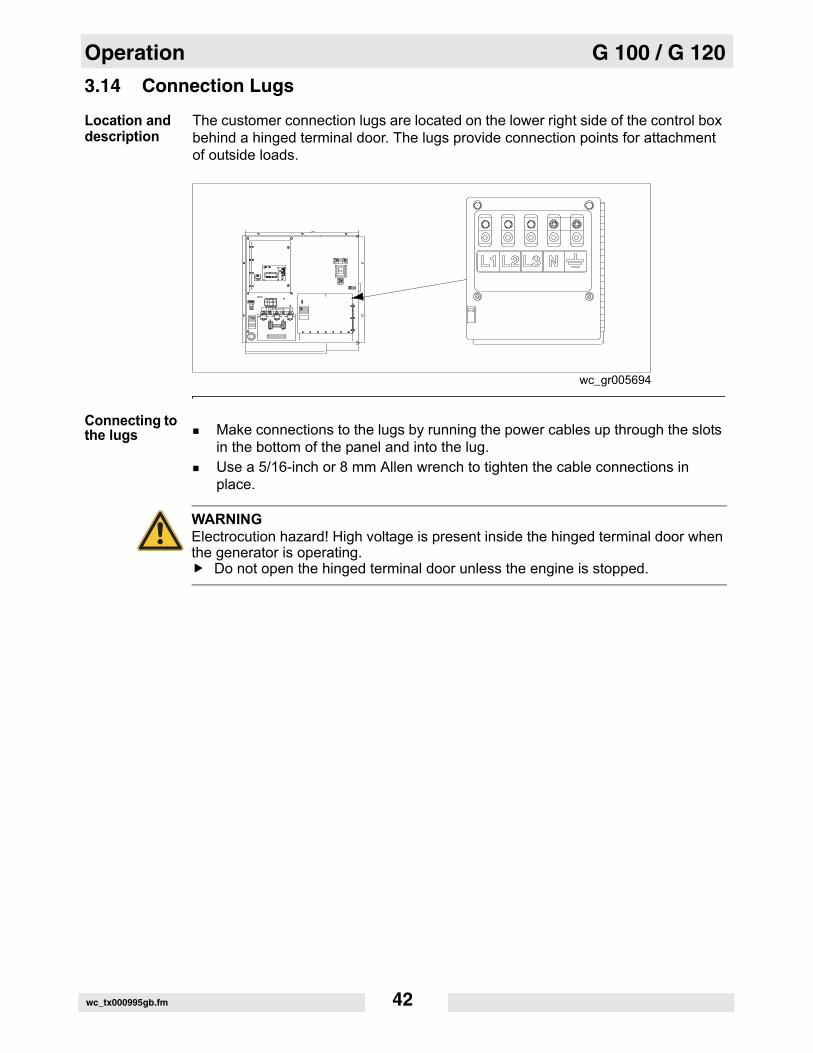
Location and description
The customer connection lugs are located on the lower right side of the control box behind a hinged terminal door. The lugs provide connection points for attachment of outside loads.
Connecting to the lugs Make connections to the lugs by running the power cables up through the slots
in the bottom of the panel and into the lug.Use a 5/16-inch or 8 mm Allen wrench to tighten the cable connections in place.
wc_gr005694
WARNINGElectrocution hazard! High voltage is present inside the hinged terminal door when the generator is operating.
Do not open the hinged terminal door unless the engine is stopped.
wc_tx000995gb.fm 42
G 100 / G 120 Operation
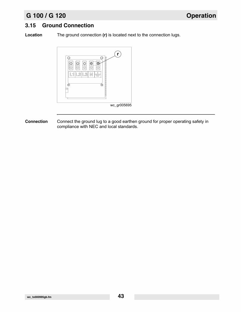
3.15 Ground Connection
Location The ground connection (r) is located next to the connection lugs.
Connection Connect the ground lug to a good earthen ground for proper operating safety in compliance with NEC and local standards.
r
wc_gr005695
wc_tx000995gb.fm 43

Operation G 100 / G 120
3.16 Convenience Receptacles
Description The generator is equipped with :
three 120V/240V twist-lock receptacles (m) rated at 50Atwo 120V duplex receptacles (n) with ground fault interrupts (GFI)
Receptacles do not connect through the main line circuit breaker. Each receptacle is protected by its own circuit breaker (k,l).
Power to the receptacles is available anytime the generator is running, even with the main line circuit breaker open.
Operating notes
When the voltage selector switch is in the 480V / 3Ø position, voltage at the duplex receptacles is 139V, and voltage at the 50A receptacles is 139/240V.When the voltage selector switch is in the 208V / 3Ø position, voltage at the 30/50A receptacles is 120/208V.When the voltage selector switch is in the 208V / 3Ø position, the voltage can be adjusted with the voltage adjustment rheostat (f) to 240V / 3Ø. The voltage at the duplex receptacles is 139V, and voltage at the 50A receptacles is 139/240V.
wc_gr005193
m
k l
n
wc_tx000995gb.fm 44

G 100 / G 120 Operation
3.17 Remote Run Terminal Block
Location The remote run terminal block (i) is located just to the left of the convenience receptacle circuit breakers.
Description The remote run terminal block provides connection points for installation of a remote start switch. When it is connected to a transfer switch, it allows the generator to be used as a stand-by power supply.
Connections When connecting a remote start switch or transfer switch, use the inner two terminals on the remote run terminal block.
Note: The bonding bar between the ground connections must remain in place at all times unless a qualified electrician determines otherwise.
wc_gr005194
i
wc_tx000995gb.fm 45
Operation G 100 / G 120
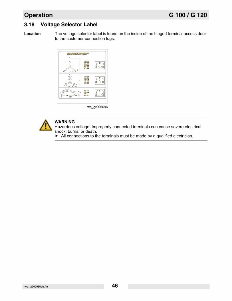
3.18 Voltage Selector Label
Location The voltage selector label is found on the inside of the hinged terminal access door to the customer connection lugs.
wc_gr005696
WARNINGHazardous voltage! Improperly connected terminals can cause severe electrical shock, burns, or death.
All connections to the terminals must be made by a qualified electrician.
wc_tx000995gb.fm 46

G 100 / G 120 Operation
3.19 Racor® Crankcase Filter
Location The Racor crankcase filter (a) is located next to the engine.
Description The crankcase filter removes oil from engine blow-by. Coalesced oil drains into the engine oil pan. Filtered air is then routed to the engine intake system.
The crankcase filter contains a high-performance element which should be replaced after every 750 hours of operation. See Replacing the Racor Filter Element in the Maintenance chapter.
Filter heater Your crankcase filter may be equipped with a thermostatically controlled heating system as shown in the illustration on the right. This system prevents water vapor from condensing and freezing on the inner walls of the filter intake hose while operating the generator in extremely cold weather.
wc_tx000995gb.fm 47

Operation G 100 / G 120
3.20 Before Starting
Explanation Before putting the generator into service, review each item on the following checklist. Because generators often run unattended for long periods of time, it is important to make sure that the machine is set up properly to reduce the possibility of malfunction.
Before starting the generator:
Exterior checks
check for damage that may have occurred during towing or travel to the jobsitecheck for debris that has lodged in vents, near the radiator, or around the fanmake sure the exhaust compartment is clean, with nothing touching the muffler or exhaust pipesmake sure that the generator is levelchock the trailer wheels
Internal and pre-operation checks
check engine oil, coolant, and fuel levels—fill as requiredcheck the fan belt and hoses on the engine for loose connections or fraying—tighten or replace as requiredmake sure that the generator is grounded to a good earthen ground per local regulations and NEC standardscheck that all electrical connections were made in compliance with local regulations and NEC standardsdetermine voltage needs—set voltage selector switch and make correct terminal connectionsclose and secure side panel access doorsreview and follow safety instructions found in the front of this Operator’s Manual
WARNINGPersonal injury hazard. Failure to follow the listed procedures may cause injury to personnel or damage to the generator.
Make sure that all persons setting up the generator are certified or fully trained on the installation of the generator.
wc_tx000995gb.fm 48
G 100 / G 120 Operation
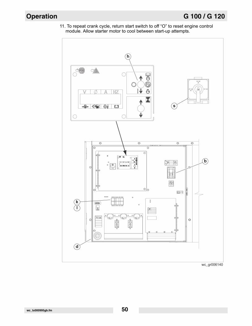
3.21 Manual Starting
Explanation Before starting the generator set for the first time, thoroughly review the “Before starting” checklist in the previous section. Proceed with generator starting only after checking each item in that section.
Thoroughly read and make sure you understand the engine operator’s manual supplied with the generator. Follow the steps below in the order listed.
Start-up procedure
Follow the procedure below to start the generator.
1. Make sure the engine start switch (h) is in the off “O” position.2. Check position of the voltage selector (s) and make sure it is set for the desired
voltage output. Lock the switch in place.3. Turn main line circuit breaker (b) to off “O”.4. Turn convenience receptacle circuit breakers (k,l) to off “O”. 5. Move engine start switch to “REMOTE START” to check operation of engine
control module. The LCD panel should momentarily display “UNIT IN AUTO” and engine information. Check fuel level and battery values.
6. Press the emergency stop button (d). The LCD panel should read “EMERGENCY STOP”. Pull the emergency stop button after verifying the display, and return the engine start switch to off “O”.
7. Start engine by moving the engine start switch to the “START/RUN” position. 8. After displaying “INITIALIZING” sequence, the LCD display will read
“STARTING ENGINE” as the engine begins its crank cycle. The normal cycle is for the engine to crank for 15 seconds, then rest for 10 seconds. This cycle will repeat three (3) times.
9. If the engine does not start within this time, the engine control module will shut down the engine and “—” will be displayed on the LCD panel.
10. See Basic Troubleshooting to identify possible causes and remedies for the starting problem. Correct the problem before attempting to start the engine again.
CAUTIONPersonal injury hazard. Failure to match phase rotation and voltage may cause equipment connected to the generator to operate incorrectly.
When using the generator as a standby or substitute power supply, make sure the voltage and phase rotation of the line connections match those of the utility lines or of any other power source normally used.
CAUTIONPossibility of accidental equipment start-up. If the contacts on any remote switch linked to the generator are closed, the generator could start unexpectedly when the engine start wwitch is moved to the REMOTE START position.
Before placing the engine start switch (e) in the REMOTE START position, verify that the contacts on any remote switch linked to the generator set are OPEN.
wc_tx000995gb.fm 49
Operation G 100 / G 120
11. To repeat crank cycle, return start switch to off “O” to reset engine controlmodule. Allow starter motor to cool between start-up attempts.
wc_gr006140
s
d
k
l
h
b
120 / 2083Ø
277 / 4803Ø
120 / 240
wc_tx000995gb.fm 50

G 100 / G 120 Operation
3.22 Running the Generator
Switch positions
Leave the engine start switch (e) in the START/RUN position while the generator is operating.
If the generator was started using a remote switch, leave the engine start switch in the REMOTE START position.
Let the generator run for a few minutes to warm the engine before closing the main circuit breaker.
While the generator is running, check for excessive vibration, oil leaks, or coolant leaks.
CAUTIONPossibility of unexpected equipment start-up.
Disconnect all attached electrical devices before starting the machine. Before closing breakers, make sure that any electrical devices attached down-stream from the generator will not start up unexpectedly.Before placing the engine start switch in the REMOTE START position, verify that the contacts on any remote switch linked to the generator set are open. This will prevent the generator from immediately starting when the engine start switch is moved to the REMOTE START position.
wc_tx000995gb.fm 51

Operation G 100 / G 120
3.23 Engine Power Correction Factors
Performance data conditions
Performance data on John Deere engines are measured at the following standard conditions:
744 mm (29.31 in.) of mercury dry air pressure183 m (600 ft.) altitude0% relative humidity25°C (77°F) air intake temperature40°C (104°F) fuel inlet temperature
Refer to the table below to estimate the engine power decrease in percent as environmental factors vary from the standard conditions.
Engine power correction factors
Model
Fuel temprise of 1°C (1.8°F)
Air temprise of -12°C (10°F)
Relative humidity rise of 10%
Altituderise of 305 m (1000 ft) above 3050 m (10,000 ft)
Altituderise of 305 m (1000 ft) below 3050 m (10,000 ft)
G 100G 120
None (ECU compensated)
0.50 0.07 4.00 0.5
wc_tx000995gb.fm 52

G 100 / G 120 Operation
3.24 Stopping the Generator
Before shutdown
Check with other personnel on the jobsite and let them know that power is being turned off. Make sure that the power shutdown will not create any hazards by turning off devices such as pumps, heaters, or lights that may need to be kept on.
Shutdown procedure
To shut down the generator:
1. Remove all loads from generator.2. Open (turn to off “O”) main line circuit breaker.3. Let engine run for approximately 5 minutes to allow it to cool down.4. Move Engine Start Switch to the off “O” position.
3.25 Cold Weather Starting
Prerequisites Before starting the generator in cold weather make sure that:
the battery is at peak powerthe correct weight motor oil is being usedthe starter motor is in good condition
During operation
The cold starting aid will automatically activate when the air temperature is low enough. The ECM will notify you that a preheat is in effect.
wc_tx000995gb.fm 53
Operation G 100 / G 120
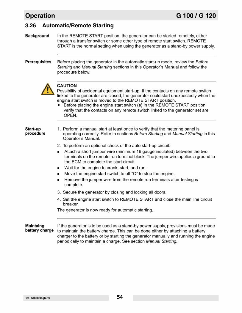
3.26 Automatic/Remote Starting
Background In the REMOTE START position, the generator can be started remotely, either through a transfer switch or some other type of remote start switch. REMOTE START is the normal setting when using the generator as a stand-by power supply.
Prerequisites Before placing the generator in the automatic start-up mode, review the Before Starting and Manual Starting sections in this Operator’s Manual and follow the procedure below.
Start-up procedure
1. Perform a manual start at least once to verify that the metering panel is operating correctly. Refer to sections Before Starting and Manual Starting in this Operator’s Manual.
2. To perform an optional check of the auto start-up circuit:Attach a short jumper wire (minimum 16 gauge insulated) between the two terminals on the remote run terminal block. The jumper wire applies a ground to the ECM to complete the start circuit. Wait for the engine to crank, start, and run.Move the engine start switch to off “O” to stop the engine. Remove the jumper wire from the remote run terminals after testing is complete.
3. Secure the generator by closing and locking all doors.4. Set the engine start switch to REMOTE START and close the main line circuit
breaker. The generator is now ready for automatic starting.
Maintaing battery charge
If the generator is to be used as a stand-by power supply, provisions must be made to maintain the battery charge. This can be done either by attaching a battery charger to the battery or by starting the generator manually and running the engine periodically to maintain a charge. See section Manual Starting.
CAUTIONPossibility of accidental equipment start-up. If the contacts on any remote switch linked to the generator are closed, the generator could start unexpectedly when the engine start switch is moved to the REMOTE START position.
Before placing the engine start switch (e) in the REMOTE START position, verify that the contacts on any remote switch linked to the generator set are OPEN.
wc_tx000995gb.fm 54

G 100 / G 120 Operation
3.27 Remote/Transfer Switch
Background A transfer switch is designed to transfer electrical loads from the normal power source (utility) to the emergency power source (generator) when normal voltage falls below a prescribed level.
The transfer switch automatically returns the load back to the normal source when power is restored back to operating levels.
Precautions Installation of a transfer switch or other type of remote starting device is the responsibility of the generator user. Installation of such devices must be performed by a qualified electrician following all directions supplied by the manufacturer of the switch. If attaching the generator to a power supply normally serviced by a utility company, notify the utility company and check local and state regulations.Familiarize yourself with all instructions and warning labels supplied with the switch.
WARNINGElectrocution hazard. Failure to isolate the generator from the utility’s electrical distribution system could cause output from the generator to backfeed into the utility lines and cause injury or death to utility workers!
When the generator is used as a standby power supply, it must be equipped with a device which isolates it from the utility’s distribution system.An isolation device is also required if the generator is being used as a backup to some other type of power supply system.
CAUTION! Possibility of injury or equipment damage. Failure to match phase rotation and voltage may cause equipment connected to the generator to operate incorrectly.
When using the generator as a standby or substitute power supply, make sure the voltage and phase rotation of the line connections match those of the utility lines or of any other power source normally used.
DANGERElectrocution hazard. Lethal voltage is always present in the transfer switch once it has been properly installed.
Disconnect power before servicing the transfer switch.
wc_tx000995gb.fm 55

Maintenance G 100 / G 120
4 Maintenance
4.1 Periodic Maintenance Schedule
*Replace the air filter cartridge when yellow indicator of the engine air filter gauge reaches the red line.**Change the oil after the first 100 hours, then every 250 hours. ***If John Deere antifreeze is used, the flushing interval may be extended. See engine operator’s manual.
Daily Every 50 Hrs or 2 weeks
Every 250 Hrs or 10 weeks
Every 600 Hrs or 12 Mo
Every 1200 Hrs or 24 Mo
Every 2000 Hrs Other
Check engine oil and coolant level
Check engine air filter gauge & air cleaner dust cap *
Visual walkaround inspection
Check tire inflation, tread wear and lug nuts before towing
Check fuel filter
Service the battery
Change engine oil and replace oilfilter**
Clean unit inside and out
Check air intake hoses, connec-tions, and system
Replace fuel filter element
Check automatic belt tensioner and belt wear
Check cooling system
Perform coolant solution analysis & add SCA's
Grease axle
Pressure test cooling system
Flush cooling system***
Check and adjust engine valve clearance
Check brake fluid level in trailer at least monthly
Replace the Racor® filter elementevery 750 hours
wc_tx000996gb.fm 56

G 100 / G 120 Maintenance
4.2 Breaking In New MachinesRun the generator at least 60–100% of continuous load for the first 100 hours.Change engine oil and replace oil filter after the first 100 hours.
4.3 Resetting the Periodic Maintenance Timer
Background After maintenance has been performed on the generator, it is necessary to reset the periodic maintenance timer.
Operation If the periodic maintenance timer is at zero, press the ENG. HRS switch UP and hold for 10 seconds until the “TIME TO SERVICE” resets to 250 hours.If the service time is greater than zero (maintenance was performed prior to the timer running out) press and hold the ENG. HRS switch UP and hold for 30 seconds. This will reset the “TIME TO SERVICE” to 250 hours.
wc_tx000996gb.fm 57

Maintenance G 100 / G 120
4.4 Replacing the Air Filter ElementPrerequisites Machine shut down
Yellow indicator of the engine air filter gauge has reached the red line
Background The air cleaner assembly contains a one-piece single element air filter cartridge (c). This cartridge must be replaced when the yellow indicator of the engine air filter gauge reaches the red line.
Procedure Follow the procedure below to replace the primary air filter element.
5. Remove the end cover (d), then discard the entire air filter cartridge (c). 6. Insert a new air filter cartridge.7. Re-install the end cover, making sure that the dust cap is clean and pointing
downward.8. Make sure that the intake piping (a) is fully engaged over the neck of the filter to
ensure a good seal.
Maintenance Periodically, make sure the inlet pipe is free from obstructions.Check all connections and make sure they are snug. An air leak at the neck clamp, gauge connection, or intake pipe can quickly lead to engine damage.If the filter housing, gauge connection, neck, or inlet pipe are crushed or damaged, replace them immediately.
wc_gr005198
ca d
wc_tx000996gb.fm 58

G 100 / G 120 Maintenance
4.5 Replacing the Racor® Filter Element
When Replace the filter element after every 750 hours of operation, or whenever the red filter service indicator appears.
Prerequisites Engine is stoppedReplacement filter element and O-rings are availableShop towels are available to wipe up spills
Procedure Follow the procedure below to replace the filter element.
1. Release the latches (1) holding the canister (3) to the filter head assembly (2).2. Drop the canister to expose the filter element (4). A small amount of oil may be
present inside the canister, so use caution to avoid spills.3. Pull the filter element down to remove it.4. Remove the O-ring (5) from the top of the filter element end cap (7). Also,
remove the O-ring (6) from the bottom of the filter head assembly.
Note: Dispose of the used filter element and O-rings in accordance with local envi-ronmental protection regulations.
5. Install a new O-ring on the bottom of the filter head assembly. Also, verify that a new O-ring is on the top end cap of the replacement filter element.
6. Push the filter element end cap into the hole in the bottom center of the filter head assembly.
7. Replace the canister and align the latches on the canister with the boss on the filter head assembly.
8. Clamp the latches and snap them closed.
wc_gr006384
3
1
6
7
2
5
4
wc_tx000996gb.fm 59
Maintenance G 100 / G 120
4.6 Lubricating the EngineChecking oil Check engine oil daily before starting engine.
Do not operate engine if oil level is below ADD mark on dipstick. Always keep oil level within the crosshatch pattern or “full” mark on dipstick.Change oil after first 100 hours of operation and every 250 hours thereafter. Refer to the engine manufacturer’s Operator’s Manual for lubrication specifications.
Break-in Service
This engine is factory-filled with John Deere Engine Break-in Oil. Operate the engine at heavy loads with minimal idling during the break-in period. Do not exceed 100 hours of operation with break-in oil.If the engine has significant operating time at light load, or more oil is required in the first 100 hour period, a longer break-in period may be required. In these situations, an additional 100 hour break-in period is recommended using a new change of John Deere Engine Break-In Oil and a new John Deere oil filter.
NOTICE: Do not add more oil until the oil level is BELOW the ADD mark on the dipstick. John Deere Engine Break-In Oil (TY22041) should be used to make up any oil consumed during the break-in period.
During the first 20 hours, avoid prolonged periods of no load or sustained maximum load operation. If engine is to run for longer than 5 minutes without a load, shut unit down.After the first 100 hours, change engine oil and replace engine oil filter. Fill crankcase with seasonal viscosity grade oil.
WARNINGBurn hazard. Engine, engine oil, muffler, and exhaust pipes become extremely hot during operation.
Stop the engine and allow the machine to cool before checking the oil or replacing the engine oil or oil filter cartridge.
wc_tx000996gb.fm 60

G 100 / G 120 Maintenance
4.7 Checking the Engine Coolant LevelPrerequisites Machine shut down
Engine cool
When Dailyl
Procedure Follow the procedure below to check the engine coolant level.
1. Open the access cover on the roof.2. Open the radiator filler cap slowly in order to relieve the pressure. Remove the
filler cap after the pressure has been released.3. Verify that the coolant level of the radiator is 3/4-inch below the bottom of the
filler neck. Add more coolant if necessary to maintain this level.
4. Inspect the radiator filler cap and filler cap seal for damage. Clean the radiator filler cap or replace it if necessary.
5. Re-install the radiator filler cap.
NOTICE: Solutions of antifreeze and supplemental coolant additives MUST be used year-round. Automotive-type coolants do not contain the correct coolant additives to protect heavy-duty diesel engines. They often contain a high concentration of silicates which can damage the engine and cooling system. Refer to engine operator’s manual for coolant recommendations.
WARNINGBurn hazard. Engine coolant is hot and under pressure at operating temperature. It can cause severe personal injury.
Check the coolant level only after the engine has been shut down and is cool.
WARNINGBurn hazard. Coolant can contain alkali.
Avoid coolant contact with skin and eyes.
wc_tx000996gb.fm 61

Maintenance G 100 / G 120
4.8 Maintaining the TrailerTires Keep tires inflated to the proper pressure as shown on the tire sidewall.
Check tread periodically for wear.Replace tires as required.
Wheels Check that lug nuts holding wheels are tight. Replace any missing lug nuts immediately.
Axle Hubs Grease axle hubs using a good wheel bearing grease.
Brakes Check operation of brakes before each trip.Check level of brake fluid in actuator at front of trailer at regular intervals. Fill brake fluid to approximately 1-inch below top of reservoir using DOT-3 heavy-duty brake fluid. Tighten filler plug securely.
Note: If fluid level has fallen too low, bleed brake lines to remove any air trapped in lines. Then fill to proper level with clean brake fluid.
wc_tx000996gb.fm 62

Factory-Installed Options
5 Factory-Installed Options
This machine may be equipped with one or more of the following factory-installed options. To verify if any of these options are installed on your machine, contact the Wacker Neuson Corporation at 1-800-770-0957. A nameplate listing the Model Number, Item Number, Revision, and Serial Number is attached to each unit. Please have this information available when contacting Wacker Neuson.
Note: The illustrations shown in this chapter represent typical installations. The factory-installed options on your machine may look different.
5.1 Block Heater
The engine block heater option includes a block heater (a) with a cord (b). The function of the block heater is to heat the engine coolant/engine block to improve cold-weather engine starting. Plug the cord into a 120V power supply.
wc_tx000997gb.fm 63

Factory-Installed Options
5.2 LCD Strip Heater
The LCD strip heater option includes a thermostat module (a) and a clear heater strip that is bonded to the LCD (b) of the ECM.
The purpose of the strip heater is to prevent the LCD from being damaged by extremely cold temperatures. The resistance of the coiled element of the heater is sensed by the thermostat. The resistance of the element changes with temperature. At approximately -30°C (-22°F), the resistance value triggers the thermostat to send power to the element. The LED (c) of the thermostat module flashes during operation.It is important to note that the LCD strip heater is always on and thus draws power (a very small amount) from the battery even when the unit is not running. If the battery should fail, the heater will also fail. Be sure to keep the battery charged when the generator is not in use.
wc_tx000997gb.fm 64

Factory-Installed Options
5.3 Low Coolant Shutdown
The low-coolant shutdown system consists of an electronic sensor that monitors coolant level. The sensor (a) is mounted to the radiator and wired into the ECM. The sensor probe (b) is submerged in radiator coolant.
If the probe senses no coolant, it sends a signal to the ECM. The ECM program includes a 10-second timer to protect from nuisance shutdowns. If after the ten seconds coolant levels are still sensed as being low, the ECM shuts down the engine. The ECM will then display the “FAULT LOW WATER LEVEL”. Allow the engine to cool before adding additional coolant.
If it is necessary to open the radiator, only do so with the engine off, and only when coolant is cool enough to touch with bare hands. Slowly loosen the radiator cap to relieve pressure first, before removing it completely.
Note: The sensor may be disabled by unplugging the wire harness. This action will not shut down the machine.
WARNINGBurn hazard. Pressurized coolant is very hot and can cause serious burns.
Do not remove the radiator cap while the engine is hot.
wc_tx000997gb.fm 65

Factory-Installed Options
5.4 Lube Level Maintainer
The lube level maintainer system protects the engine from low oil levels by providing an additional 6-quart oil reservoir. Oil from the reservoir is gravity-fed from the oil reservoir (a) through the control valve (b) and into the engine oil pan as needed.
The valve includes a sightglass (c) through which the oil level can be seen. This oil level is the same as that measured by the engine dipstick. A float inside the valve detects low oil levels and opens the valve to supply the needed oil. The system is wired to the ECM and includes a low oil shutdown in case the oil in the reservoir is depleted. If the engine shuts down due to low oil, the ECM will display “FAULT LOW OIL LEVEL”. Fill the engine and the additional oil reservoir with oil before placing the generator back into service.
NOTICE: To prevent overfilling the engine with oil, place the shutoff valve (d) in the closed position when moving or towing the generator. Once the generator is in position, open the valve.
wc_tx000997gb.fm 66

Factory-Installed Options
5.5 Temperature-Activated Shutters
The shutters (a) are mounted to the top of the generator enclosure.
The shutters are designed to keep the engine compartment warm, thus increasing engine temperature during cold weather operation. The shutters are activated through a wax-pellet actuator (b) that is connected to the generator's cooling system. As radiator coolant warms, the wax-pellet actuator engages a linkage (c) that opens the shutters. As the coolant cools, the shutters close.
5.6 Lockable Battery Disconnect
A lockable ON/OFF switch is available which disconnects the battery. A padlock (not included) securely locks the switch in the OFF position. If equipped, the battery disconnect switch is mounted to the upper skid beneath the access door on either the right or left side of the machine.
NOTICE: Do not use the battery disconnect switch while the engine is running. Damage to electrical components may occur.
wc_tx000997gb.fm 67
Schematics G 100 / G 120
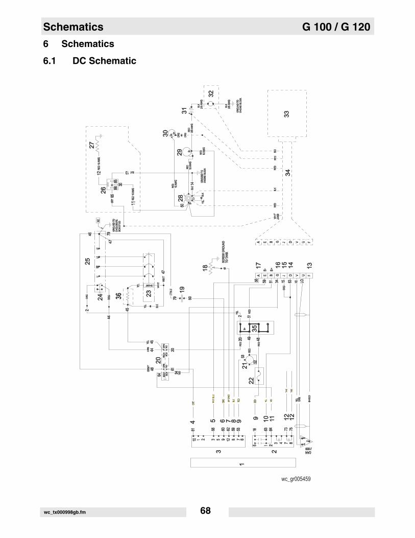
6 Schematics
6.1 DC Schematic
wc_gr005459
wc_tx000998gb.fm 68
G 100 / G 120 Schematics
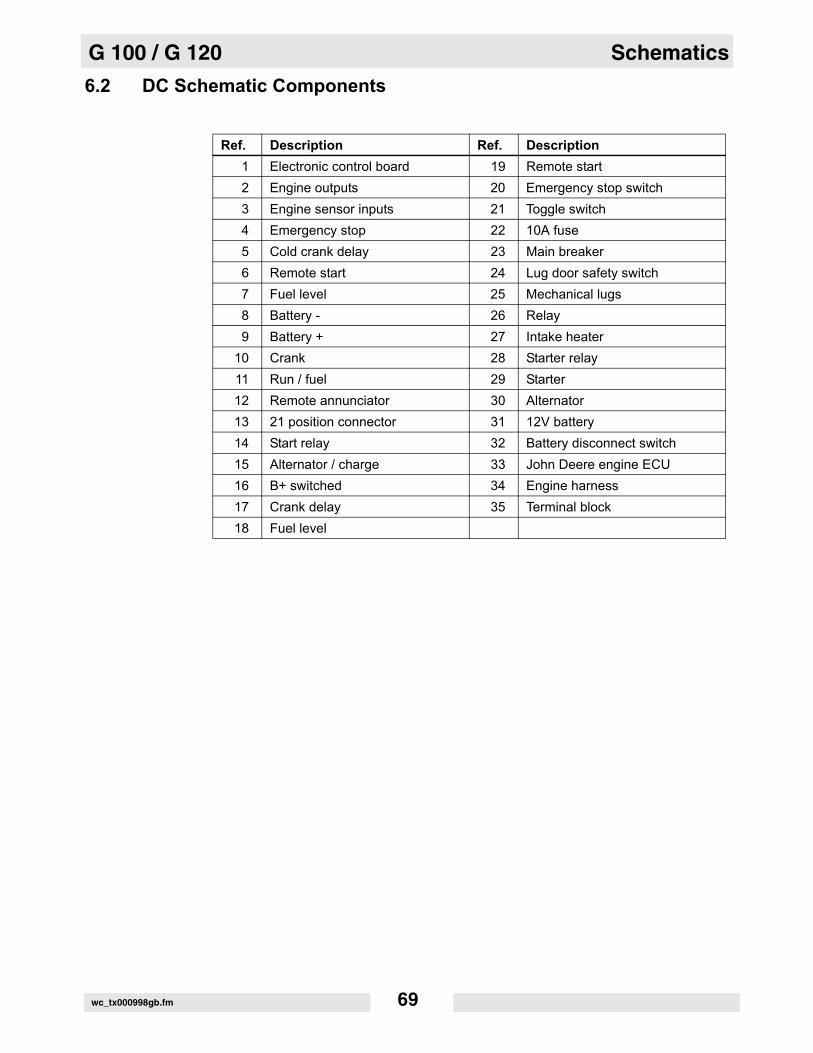
6.2 DC Schematic Components
Ref. Description Ref. Description1 Electronic control board 19 Remote start2 Engine outputs 20 Emergency stop switch3 Engine sensor inputs 21 Toggle switch4 Emergency stop 22 10A fuse5 Cold crank delay 23 Main breaker6 Remote start 24 Lug door safety switch7 Fuel level 25 Mechanical lugs8 Battery - 26 Relay9 Battery + 27 Intake heater
10 Crank 28 Starter relay11 Run / fuel 29 Starter12 Remote annunciator 30 Alternator13 21 position connector 31 12V battery14 Start relay 32 Battery disconnect switch15 Alternator / charge 33 John Deere engine ECU16 B+ switched 34 Engine harness17 Crank delay 35 Terminal block18 Fuel level
wc_tx000998gb.fm 69

Schematics G 100 / G 120
6.3 AC Schematic
1111
1616 15151010 14149
RED
RED RED
RED
(PO
WER
)(P
OW
ER)
GR
NG
RN
BLK
BLK
(SEN
SIN
G)
(SEN
SIN
G)
1111
9
5
7
3
1
VIO
VIO
WH
TW
HT
5C5C 7 5A5A5B5B 5 4A4A 4 333A3A 126
60H
Z JU
MPE
R60
HZ
JUM
PER
BLU
/WBL
U/W
AMPAMP HZHZ VOLTVOLTSTABSTAB
25 BRN 25 BRN
26 BRN 26 BRN
18181313
63
T11
T11
BLK
BLK
T9T9L3L3
T8T8T4T4
GRN
GRN
T3T3
21 B
LK21
BLK
22 B
LK22
BLK
19 B
LK19
BLK
20 B
LK20
BLK
X Y YX
23 B
LK23
BLK
Y
24 B
LK24
BLK
X
G W W WGG
L1L1
1717 1818
99
14141010
13132121 2222
2525 2626
L2L2
N
YEL
(+)
YEL
(+)
BLU
(-)
BLU
(-)
4
8
1010
1212
6
2
T7
T7
T5
T5
T12
T12
20201919
161615151111
24242323
28282727
43434141
T10
T10
17171212
BR
NB
RN
LT B
LULT
BLU
LT B
LULT
BLU
LT B
LULT
BLU
LT B
LULT
BLU
LT B
LULT
BLU
GR
N/Y
EL
GR
N/Y
EL
GR
N/Y
EL
GR
N/Y
EL
GR
N/Y
EL
GR
N/Y
EL
GR
N/Y
EL
GR
N/Y
EL
GR
N/Y
EL
GR
N/Y
EL
1717 9 12121111 1414 1616
NGG
BLK
BLK
BLK
BLK
G N
10101818
315151313
L3L3L2L2
L1L1
SHUNT SHUNT
BLU
BLU
BLU/W BLU/W
BLK
BLK
BLK
BLK
BLK
BLK
BLK
BLK
2 1 45
18
BLK
BLK
7
BLK
BLK
8
BLK
BLK
R2R2 R1R1
5 4 76
5 6
1 2C
T-3
CT
-3
BLK BLK
BLK BLK
BLK BLK
CT
-2C
T-2
CT
-1C
T-1
OR
NO
RN
CT
3C
T3
CT
CO
MM
ON
CT
CO
MM
ON
39
39
4
CT
-3C
T-3
BLK
BLK
2
7
43
8
CT
-2C
T-2
CT
-1C
T-1
YE
LY
EL
BR
NB
RN
CT
2C
T2
CT
1C
T1
38
38
37
37
BR
NB
RN
YE
LY
EL
OR
NO
RN
L3L3 L1L1L2L2
41
41
42
42
43
43
5 6
2 3
4
1 2
3
WH
TW
HT
136
36
BR
NB
RN 1212
12
15
28
25
27
24
23
16
18
66
7 81
0
81
0
81
0
14
21
7
17
20
22
21
26
15 3 4
wc_tx000998gb.fm 70

G 100 / G 120 Schematics
6.4 AC Schematic Components
Ref. Description Ref. Description
1 Lug safety limit switch 16 Generator
2 Mechanical lugs 17 Voltage regulator
3 Plug 3 - current transformer 18 Voltage adjustment rheostat
4 Plug 4 - line voltage inputs 19 Terminal block
5 Shunt 20 Exciter
6 120V 20A GFI receptacle 21 Stator
7 120V breaker 22 Rotor
8 240V 50A breaker 23 Rectifier
10 240V 50A receptacle 24 Rotor winding
12 Engine control module 25 Main stator windings
13 Main breaker 26 Auxiliary stator winding
14 Bond bar 27 Stator
15 Voltage selector switch 28 Terminal strip
Wire Colors
BLK Black RED Red ORN Orange
GRN Green VIO Violet LT Light
BLU Blue WHT White
YEL Yellow BRN Brown
wc_tx000998gb.fm 71
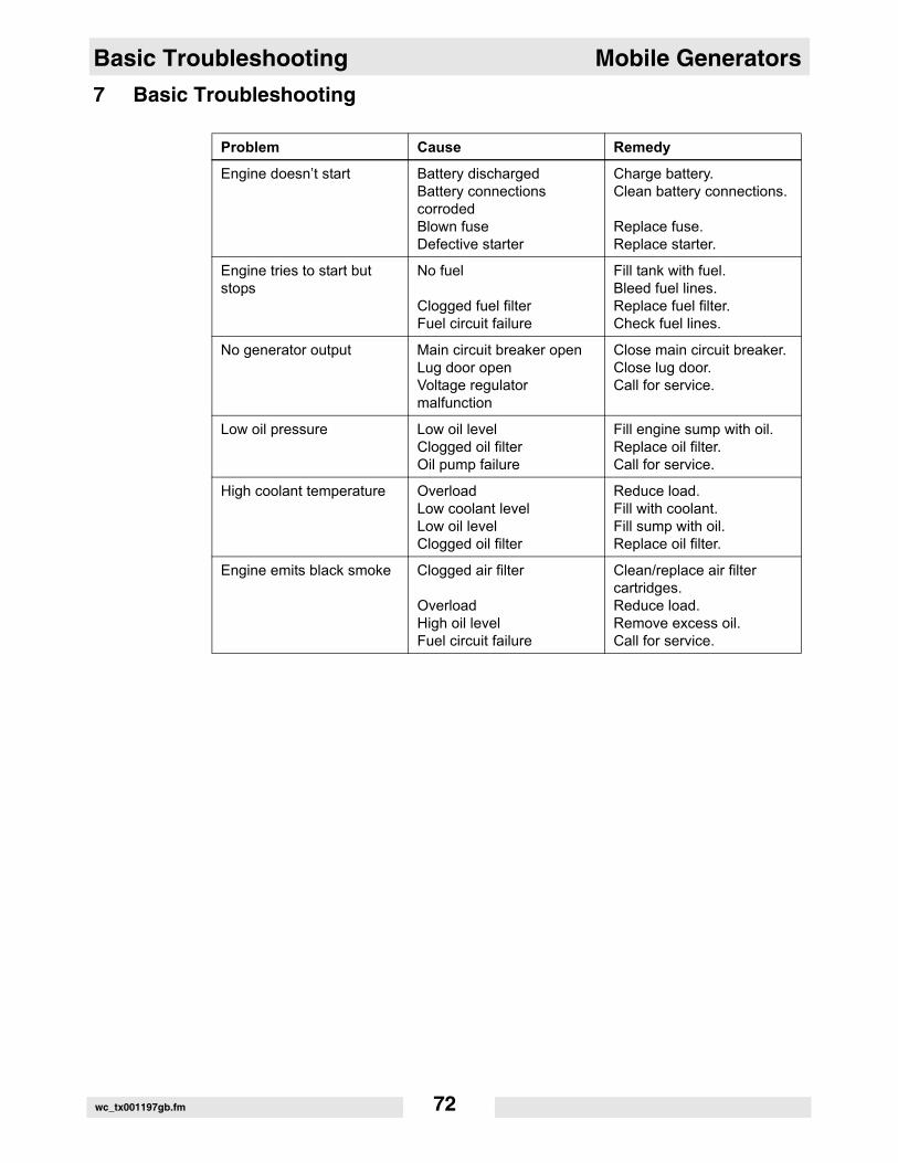
Basic Troubleshooting Mobile Generators
wc_tx001197gb.fm 72
7 Basic Troubleshooting
Problem Cause Remedy
Engine doesn’t start Battery dischargedBattery connections corrodedBlown fuseDefective starter
Charge battery.Clean battery connections.
Replace fuse.Replace starter.
Engine tries to start but stops
No fuel
Clogged fuel filterFuel circuit failure
Fill tank with fuel.Bleed fuel lines.Replace fuel filter.Check fuel lines.
No generator output Main circuit breaker openLug door openVoltage regulator malfunction
Close main circuit breaker.Close lug door.Call for service.
Low oil pressure Low oil levelClogged oil filterOil pump failure
Fill engine sump with oil.Replace oil filter.Call for service.
High coolant temperature OverloadLow coolant levelLow oil levelClogged oil filter
Reduce load.Fill with coolant.Fill sump with oil.Replace oil filter.
Engine emits black smoke Clogged air filter
OverloadHigh oil levelFuel circuit failure
Clean/replace air filter cartridges.Reduce load.Remove excess oil.Call for service.
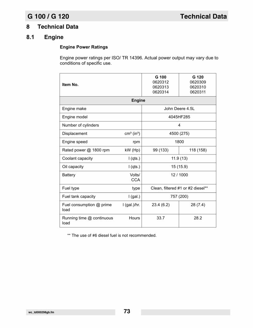
G 100 / G 120 Technical Data
8 Technical Data
8.1 EngineEngine Power Ratings
Engine power ratings per ISO/ TR 14396. Actual power output may vary due to conditions of specific use.
** The use of #6 diesel fuel is not recommended.
Item No.
G 100062031206203130620314
G 120062030906203100620311
Engine
Engine make John Deere 4.5L
Engine model 4045HF285
Number of cylinders 4
Displacement cm³ (in³) 4500 (275)
Engine speed rpm 1800
Rated power @ 1800 rpm kW (Hp) 99 (133) 118 (158)
Coolant capacity l (qts.) 11.9 (13)
Oil capacity l (qts.) 15 (15.9)
Battery Volts/CCA
12 / 1000
Fuel type type Clean, filtered #1 or #2 diesel**
Fuel tank capacity l (gal.) 757 (200)
Fuel consumption @ prime load
l (gal.)/hr. 23.4 (6.2) 28 (7.4)
Running time @ continuous load
Hours 33.7 28.2
wc_td000298gb.fm 73

Technical Data G 100 / G 120
8.2 Generator Data
Item No.
G 100062031206203130620314
G 120062030906203100620311
Generator
Make/Type Mecc Alte
Model ECP34-2S/4 ECP34-1L/4
Generator speed Hz 60
Voltage selector
V
3 position switch3Ø hi-wye, 3Ø lo-wye, 1Ø zig-zag
277/480, 120/208, 120/240
AC voltages available 1Ø (V)3Ø (V)
120, 127, 139, 240, 254, 277208, 220, 240 416, 440, 480
Frequency 60 Hz
Power factor 1Ø3Ø
1.00.8
Voltage regulation ±1.00%
Insulation class H
Sound level at 7 m (23 ft.) dB(A) 68 69
AC receptacles 2 duplex, 3 twist-lock
1Ø 120 GFI duplex Amps 2-20A
1Ø 120/240 V twist lock Amps 3–50A
Standby output kW/kVA 88/110 106/132
Prime output kW/kVA 80/100 96/120
Main breaker Amps 250 350
wc_td000298gb.fm 74

G 100 / G 120 Technical Data
8.3 Trailer and Skid Data
Item No.
G 100062031206203130620314
G 120062030906203100620311
Generator
Dry weight kg (lbs.) 2491 (5491) 2517 (5548)
Operating weight kg (lbs.) 3143 (3931) 3169 (6988)
Trailer weight without generator
kg (lbs.) 605 (1334)
GVWR kg (lbs.) 4534 (9995)
Surge brakes Fluid type Dot 3
Tires size 7.50 x 16E
wc_td000298gb.fm 75

Technical Data G 100 / G 120
8.4 Dimensions
G 100062031206203130620314
G 120062030906203100620311
a mm (in.)
2784 (110.0)b 1143 (45.0)c 1727 (68.0)
wc_gr005086
b
a
cDIESELDIESEL
STOPSTOP
PELIGROPELIGRODANGERDANGER
GEFAHRGEFAHRDANGERDANGER
WARNINGWARNING
WARNUNGWARNUNG
Lock doors. Access can cause electric shock or injury. Lock doors. Access can cause electric shock or injury. Arc flash hazard!Arc flash hazard!
Turen schliessen! Zugang kann elektrischen Schlag oder Turen schliessen! Zugang kann elektrischen Schlag oder Verletzung verursachen. Gefahr: Kurzschlusslichtbogen! Verletzung verursachen. Gefahr: Kurzschlusslichtbogen!
Fermer les portes d'acces ou il pourrait en resulter Fermer les portes d'acces ou il pourrait en resulter risque d'electrocution ou accidents de personne. risque d'electrocution ou accidents de personne. Danger: Arco de court-circuit!Danger: Arco de court-circuit!
AVERTISSEMENTAVERTISSEMENT
ADVERTENCIAADVERTENCIACierre las puertas. Ya que de orto modo existe el peligro Cierre las puertas. Ya que de orto modo existe el peligro de una descarga electrica o de lesiones personales. de una descarga electrica o de lesiones personales. Peligro: Arco voltaico de cortocircuito! Peligro: Arco voltaico de cortocircuito!
wc_td000298gb.fm 76


Wacker Neuson SE · Preußenstraße 41 · D-80809 München · Tel.: +49-(0)89-3 54 02-0 · Fax: +49 - (0)89-3 54 02-390Wacker Neuson Corporation · P.O. Box 9007 · Menomonee Falls, WI 53052-9007 · Tel. : (262) 255-0500 · Fax: (262) 255-0550 · Tel. : (800) 770-0957Wacker Neuson Limited - Room 1701–03 & 1717–20, 17/F. Tower 1, Grand Century Place, 193 Prince Edward Road West, Mongkok, Kowloon, Hongkong.Tel: (852) 3605 5360, Fax: (852) 2758 0032