plumbing for kitchens & baths supply system drain waste and vent
TRANSCRIPT

Plumbing for Kitchens & Baths
Supply System
Drain Waste and Vent

Supply System

Water Meter Housing

Water Meter
supply
Water enters the house in ¾” to 1” pipe Pressure Reduction Valve 80psi coming in Reduce to 25 -30psi

Pressure Reduction Valve

Hot Water Heater Supply
Hot Water Heater-
gas

Hot Water Heater Supply
Electrical Water
heating can account for 14%–25% of the energy consumed in your home


Water heaters with higher energy factors cost less to run. Use this factor to compare the operation cost of various water heaters.


Web Resources
www.energytrust.org/residential/index.htmlwww.earthadvantage.org/

Tankless Versus Conventional

Tankless Hot Water Heaters


Hot Water Heater Supply

Heat Pump Water Heater Supply


How hot is Hot?
Cold to Cool – 60° to 98.6° Comfort Level – 98.6° - 105° (6.4°
Range) Uncomfortable – 105° - 115° Dangerous – 116° and higher
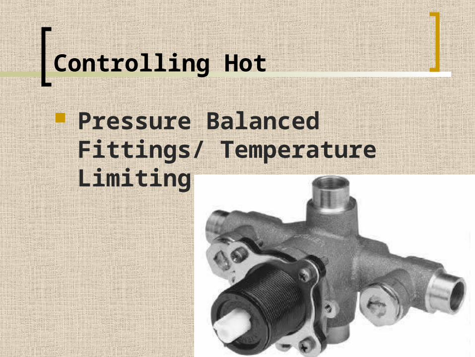
Controlling Hot
Pressure Balanced Fittings/ Temperature Limiting

Controlling Hot
Thermostatic Fittings

Supply Materials

Copper
K L M Grades

M Grade – thinnest grade used inside the home
L Grade – thicker pipe used for service
K Grade – thickest pipe used between water main and meter

Galvanized


Dielectric Union

Dielectric Union

CPVC (chlorinated polyvinyl chloride) supply

PVC Cold Water Only
Schedule 40 120psi Type 1, Grade 1
(White) Schedule 80 200psi Type 1, Grade 1
(Gray) Schedule 120 High Pressure and
Corrosion Resistant
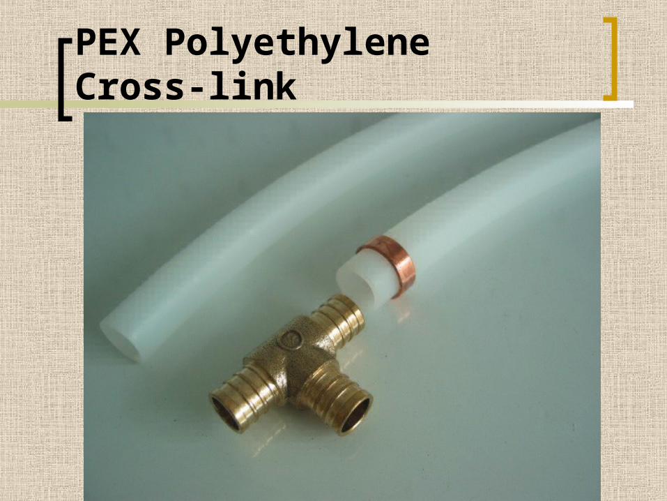
PEX Polyethylene Cross-link

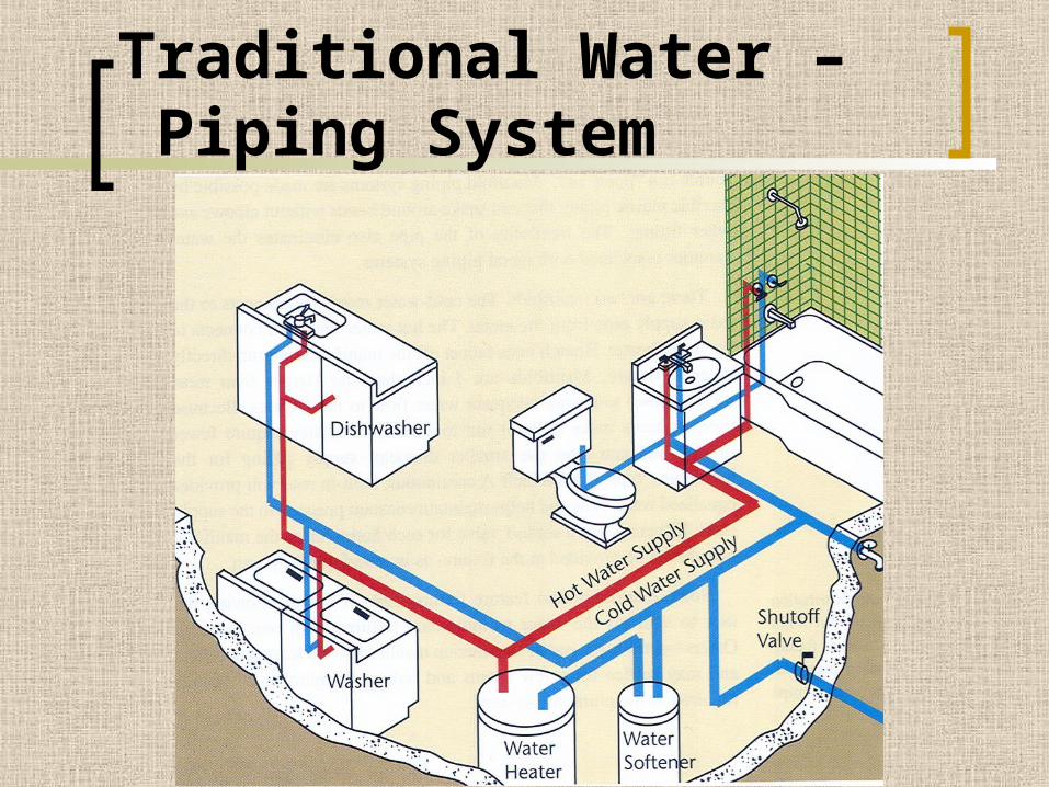
Traditional Water – Piping System
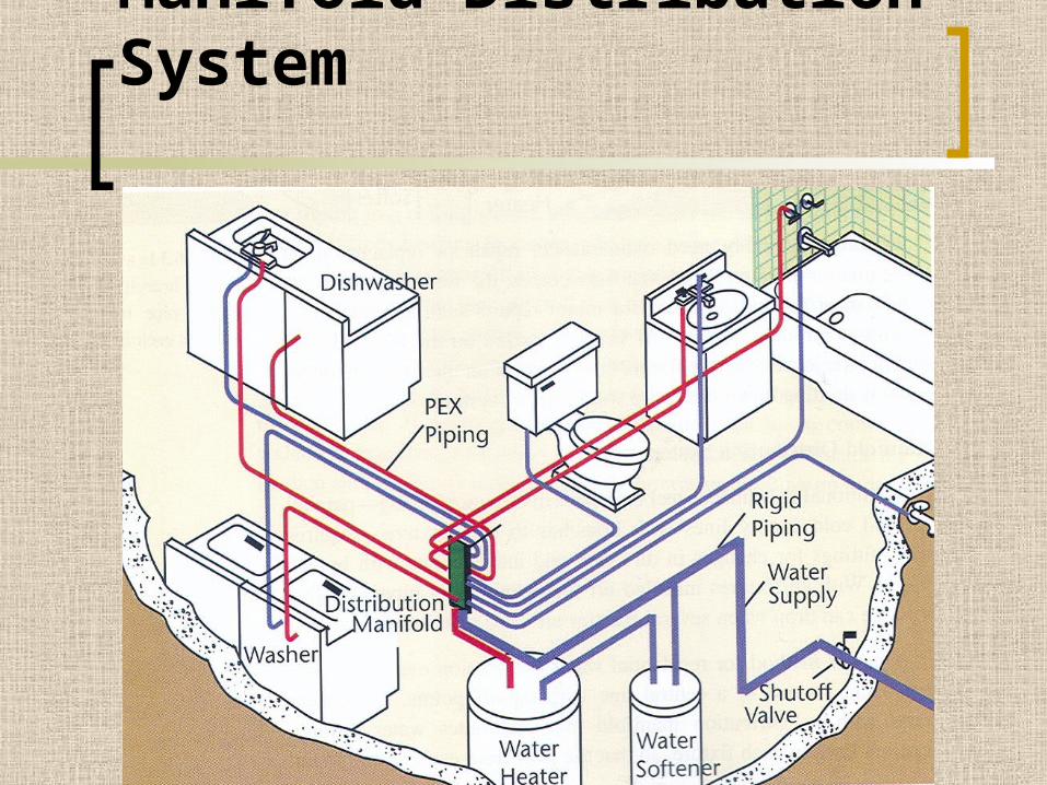
Manifold Distribution System


Floor Joist ModificationsNotching Floor Joists,
Rafters & Beams Depth of notch not to
exceed 1/6 depth of member
Width of notch not to exceed 1/3 depth of member
Notches not permitted in the center third of member
Notches at end not to exceed ¼ depth of member

Supply
If supplying water to 1-2 fixtures, use ½” water lines (A ¾” tub filler could be and exception.)
When supplying water to three or more fixtures or appliances use ¾” water line.

Plumbing Codes
Shield Plates are required for all but cast iron pipe within 1 ½” from the nearest edge of the framing member.
Plates must be 1/16” thick and extend 2” above the sole plate and below the top plate.
Pipes passing through footings or concrete walls must be protected by a pipe sleeve.
Plumbing Codes
Water drain and sewer pipes must be protected from freezing. At least 12” deep and at least 6” below the frost line. (Depends on county)
Testing of piping systems

Supply System Stop
½”¾”3/8”1/2”

Bath Design Considerations
Try to hide the stops when planning pedestal lavs.

Bath Design Considerations
Consider the finish when designing wall-hung or console lavatories


Bath Design Considerations
Consider the finish when selecting toilet trim

Bath Design Considerations
The stop for a standard toilet may need to be lowered for a low profile toilet

Bath Design Considerations
Some 1-piece toilets require a ½” stop rather than the typical 3/8” stop.

Bath Design Considerations
Every fixture should have a stop Be sure that stops will not interfere with proper
drawer function During a remodeling project always replace
existing stops, because of the low cost of stops, price should never be an issue.
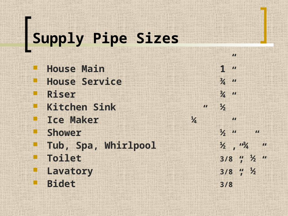
Supply Pipe Sizes
House Main 1” House Service ¾” Riser ¾” Kitchen Sink ½” Ice Maker ¼” Shower ½” Tub, Spa, Whirlpool ½”, ¾” Toilet 3/8”, ½” Lavatory 3/8”, ½” Bidet 3/8”

Wet Walls

Sharing a Wet Wall

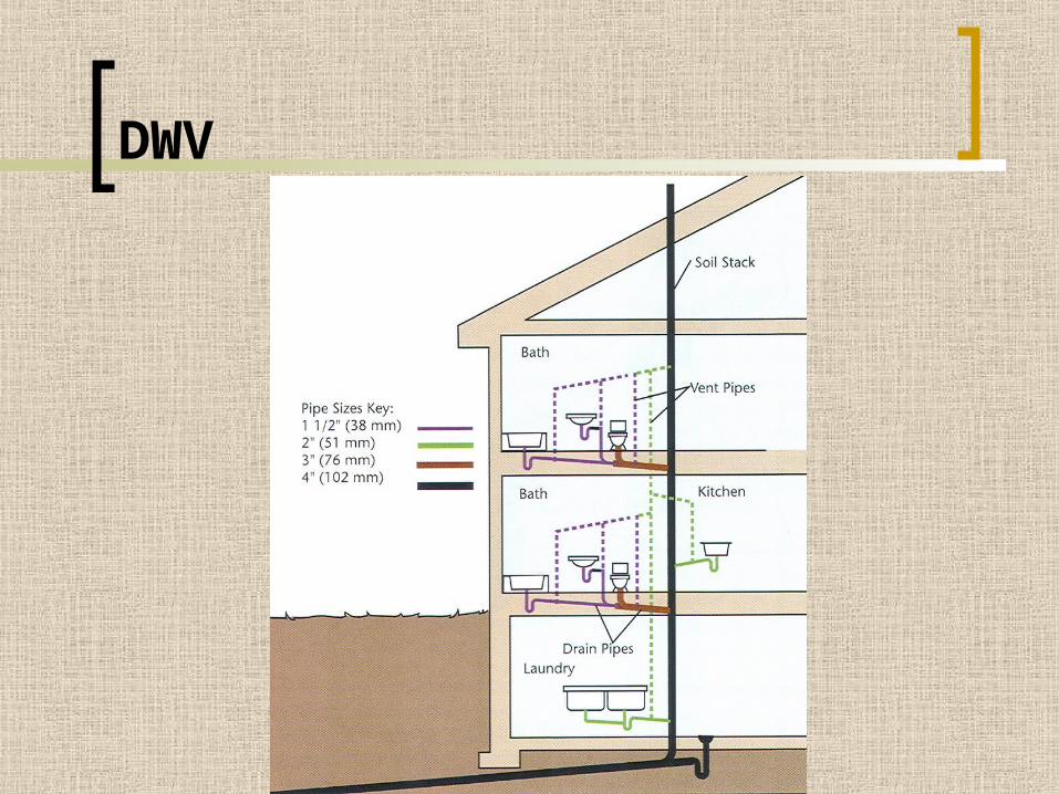
Drain Waste and Vent
DWV
DWV

DWV
Major differences between DWV and supply systems
DWV pipes are large to carry solid waste
DWV pipes slope downhill so gravity will remove the waste
DWV pipes have “soft” not sharp angles and turns
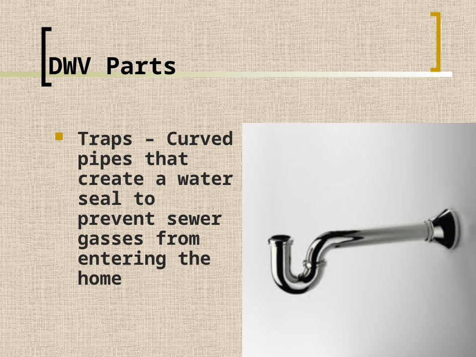
DWV Parts
Traps – Curved pipes that create a water seal to prevent sewer gasses from entering the home

DWV Parts
Drain-Piping – Horizontal pipes that carry waste for the fixtures and appliances.
Stacks – Vertical Pipes that drop the waste to lower levels of the home
House and Sewer Drains – Horizontal pipes that remove the waste from the home to the sewer or a septic tank and drain field.
Vent Stacks and Pipes – Pipes that will eventually extend through the roof of the home, preventing traps from being siphoned dry.


DRAIN PIPINGSTACKSHOUSE & SEWER DRAINS
TRAPSVENT STACKS & PIPES
Building Drain
Sewer Line
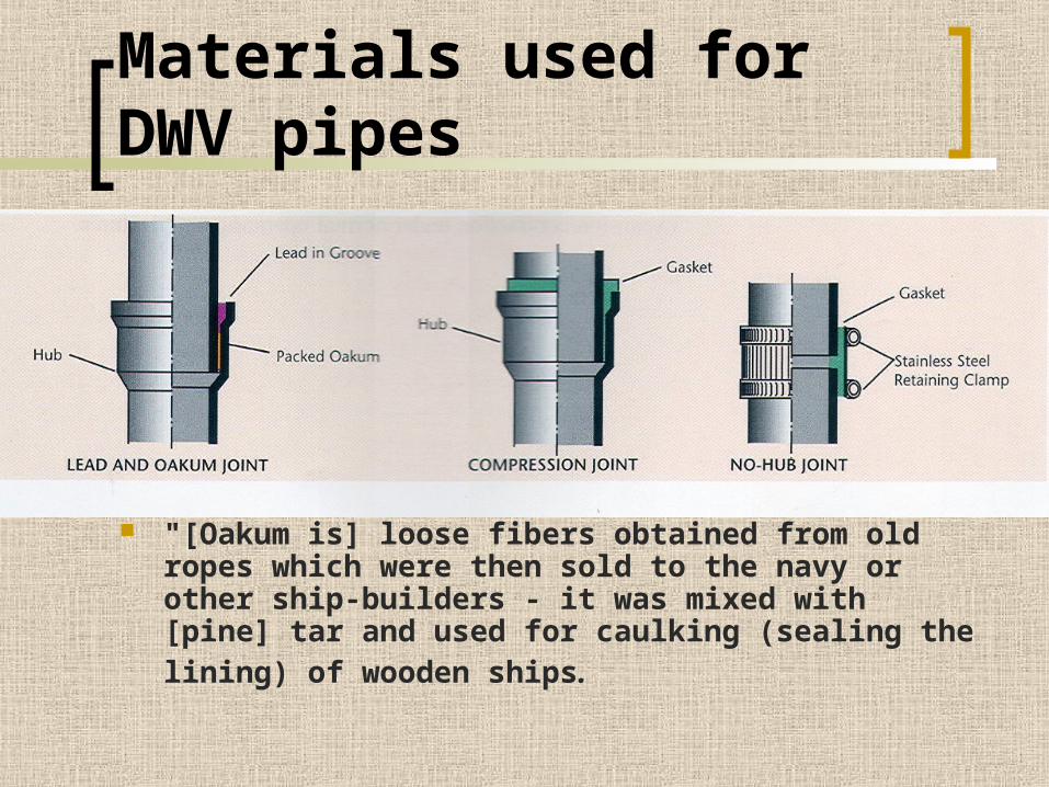
Materials used for DWV pipes
"[Oakum is] loose fibers obtained from old ropes which were then sold to the navy or other ship-builders - it was mixed with [pine] tar and used for caulking (sealing the lining) of wooden ships.


Materials used for DWV pipes
DWV
Horizontal Drain Piping – drops ¼” per foot
If 1/8” slope solid waste will settle in the pipe and create a dam.
If ½” slope or more liquid waste will flow over the solid waste without moving it along.

DWV Drain pipes vary in size
1 ¼” for small drains like bathroom lavatories
1 ½’ to 2” pipes are used on larger fixtures such as kitchen sinks, showers, bathtubs and washing machines. They will also drain multiple fixtures.
3” to 4” drains are the largest you will encounter in the home and are typically used for toilets and near the end of the DWV system.

DWV

P-Trap DWV

S-Trap and Drum Traps DWV

Trap Facts
All plumbing fixtures require traps All traps require vents A critical distance must be
maintained between the trap weir and the nearest vent

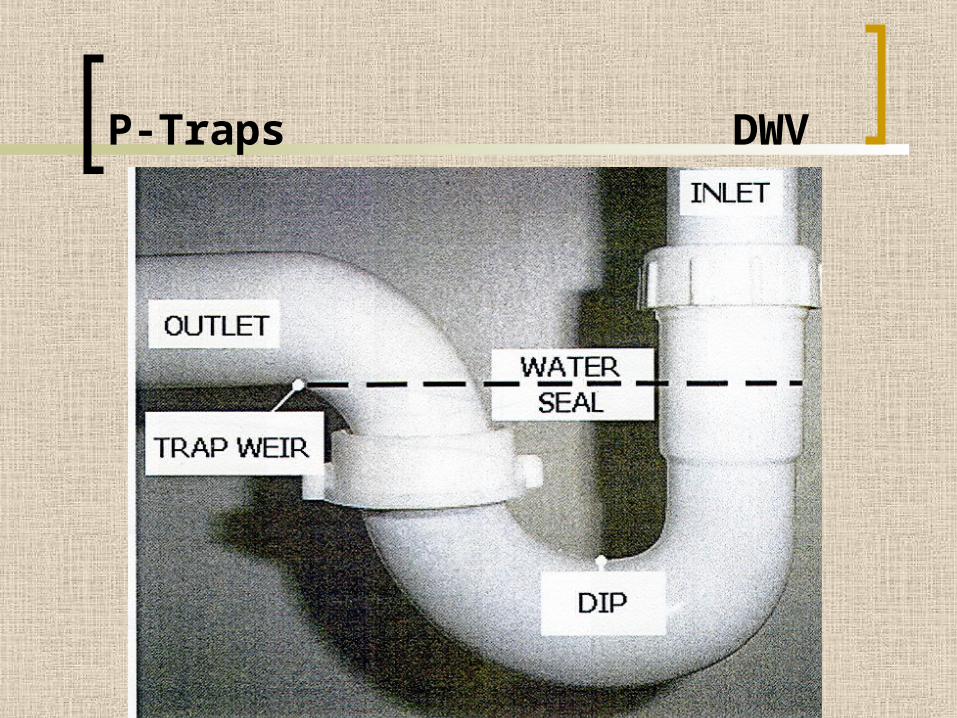
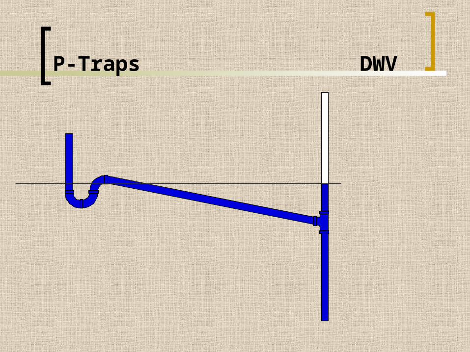
P-Traps DWV
P-Traps DWV

5 '- 0 "
1 1 / 4 "WA S TE
P IPE

Vents
Max. Distance of fixture trap from vent 1 ¼” Trap 60” 1 ½” Trap 72” 2” Trap 96” 3” Trap 144” 4” Trap 192”

Vents
What happens when the vent is too far from the trap?
Three options Increase the size of the trap Re-Vent Bow Vent (Loop Vent) Automatic Vent


Re-Venting
If a fixture is re-vented, the secondary vent cannot be connected to the main stack until it is 6” above the flood level of the highest fixture.


Bow Vent

Automatic Vent


Siphon Jet

Toilet Flanges
Toilet Flanges
10” from wall
12” from wall (most common)
14” from wall
16” old homes

Pipe Bracing