water sensitive design guide for rural residential
TRANSCRIPT
ARK Reference CD2012/172[v2] Review Date: June 2022 Uncontrolled when printed
Water Sensitive
Design Guide for
Rural Residential
Subdivisions
A WaterNSW Current Recommended Practice
May 2021

ARK Reference CD2012/172[v2] Review Date: June 2022 Uncontrolled when printed
Disclaimer
The purpose of this Design Guide is to provide information to assist those persons engaged in the design of rural residential subdivisions in the drinking water catchment. The information contained in the Design Guide is current, accurate and complete at the time of publication.
WaterNSW does not make or give any representation or warranty that compliance with the recommended practices in the guide will produce an effective subdivision design preventing all water quality impacts and will not be liable in negligence, breach of contract or statutory duty for failure of the design or the consequences of that failure.
Copyright
Copyright in this document is owned by WaterNSW. WaterNSW owns all the present and future intellectual property in all the materials authored by it.
Subjected to the above, you may photocopy, distribute and otherwise freely deal with this publication for any purpose, provided that you attribute the information to WaterNSW, and you do not alter it in any way.
WaterNSW
WaterNSW is the State-owned corporation responsible for managing bulk water supply. WaterNSW also acts to protect Greater Sydney’s drinking water catchment through protecting the quality of the water supply.
More information about WaterNSW is at www.waternsw.com.au
Acknowledgements
This ‘Water Sensitive Design Guide for Rural Residential Subdivisions’ CRP has been developed by WaterNSW with contributions by Hyder Consulting Pty Ltd, Innovations Planning, SEEC Morse McVey Pty Ltd and Laterals Planning.
Document Control
Version Published date Document administrator
v1 July 2011 Planning and Assessments, Sydney Catchments Authority
v2 May 2021 Catchment Protection, WaterNSW

ARK Reference CD2012/172[v2] Review Date: June 2022 Uncontrolled when printed
2.
Contents
EXECUTIVE SUMMARY ..................................................................................................................................... 5
1 INTRODUCTION TO DESIGN GUIDE .......................................................................................................... 7
1.1 SYDNEY’S DRINKING WATER CATCHMENT ........................................................................................................ 7 1.2 REQUIREMENTS OF STATE ENVIRONMENTAL PLANNING POLICY (SYDNEY DRINKING WATER CATCHMENT) 2011 ......... 9 1.3 WATER SENSITIVE SUBDIVISION DESIGN ELEMENTS .......................................................................................... 10
1.3.1 Integrated design ............................................................................................................................ 10 1.3.2 Accommodate existing soil and water management measures ..................................................... 10 1.3.3 Control gully and watercourse erosion ........................................................................................... 11 1.3.4 Control erosion and sedimentation on the site ............................................................................... 11 1.3.5 Control stormwater pollution ......................................................................................................... 11 1.3.6 Control wastewater pollution ......................................................................................................... 12 1.3.7 Maintain or enhance biodiversity ................................................................................................... 12 1.3.8 Ensure long-term effectiveness of management measures ............................................................ 12
1.4 RURAL RESIDENTIAL SUBDIVISION DESIGN PROCESS ......................................................................................... 13
2 SITE ANALYSIS ....................................................................................................................................... 15
2.1 DESKTOP REVIEW ..................................................................................................................................... 16 2.1.1 Data sources ................................................................................................................................... 16
2.2 SITE ANALYSIS AND CONSTRAINT MAPPING .................................................................................................... 18 2.2.1 Constraint analysis .......................................................................................................................... 18
2.3 SITE INSPECTION ...................................................................................................................................... 22 2.3.1 Identification of watercourses, drainage depressions and waterbodies ........................................ 22 2.3.2 Slope ............................................................................................................................................... 25 2.3.3 Soils ................................................................................................................................................. 25 2.3.4 Vegetation ...................................................................................................................................... 27 2.3.5 Existing Degradation ....................................................................................................................... 27 2.3.6 Existing Infrastructure ..................................................................................................................... 31 2.3.7 OTHER ............................................................................................................................................... 31
2.4 CASE STUDY – SMALL RURAL LOT SUBDIVISION ............................................................................................... 32 2.4.1 About the site .................................................................................................................................. 32 2.4.2 Site conditions and constraints to be considered ............................................................................ 33 2.4.3 Constraint overlay map ................................................................................................................... 37
2.5 CHECKLIST .............................................................................................................................................. 37
3 SUBDIVISION DESIGN ............................................................................................................................ 40
3.1 INTRODUCTION ........................................................................................................................................ 40 3.2 IDENTIFY POTENTIAL BUILDING SITES ............................................................................................................ 40 3.3 DETERMINE WASTEWATER MANAGEMENT SYSTEM AND LOCATION ..................................................................... 42 3.4 LOCATE ROADS AND ACCESS WAYS ............................................................................................................... 46
3.4.1 Grades ............................................................................................................................................. 49 3.4.2 Drainage ......................................................................................................................................... 49 3.4.3 Watercourse and drainage depression crossings ........................................................................... 51
3.5 DETERMINE LOT LAYOUT AND BOUNDARIES ................................................................................................... 57 3.6 LOCATE STORMWATER MANAGEMENT MEASURES ........................................................................................... 60 3.7 IDENTIFY EROSION AND SEDIMENTATION CONTROL MEASURES .......................................................................... 64 3.8 IDENTIFY REHABILITATION OPPORTUNITIES..................................................................................................... 65 3.9 NORBE ASSESSMENT ................................................................................................................................ 68 3.10 CASE STUDY - EXAMPLE OF A LARGE LOT RURAL RESIDENTIAL SUBDIVISION .......................................................... 69
3.10.1 Wastewater Management ......................................................................................................... 71 3.10.2 Access ......................................................................................................................................... 72 3.10.3 Poor subdivision design .............................................................................................................. 74
ARK Reference CD2012/172[v2] Review Date: June 2022 Uncontrolled when printed
3.
4 GLOSSARY ............................................................................................................................................. 76
5 ACRONYMS ........................................................................................................................................... 79
6 REFERENCES .......................................................................................................................................... 80
APPENDIX 1. DEVELOPMENT ASSESSMENT AND APPROVALS ........................................................................ 82
List of Figures
Figure 1-1 Map of Sydney’s drinking water catchment....................................................................................................... 8 Figure 2-1 Drainage depression ....................................................................................................................................... 23 Figure 2-2 Drainage depression ....................................................................................................................................... 23 Figure 2-3 A watercourse with a defined channel - an eroding watercourse can contribute large amounts of sediment to
the waterway and degrade water quality ........................................................................................................ 24 Figure 2-4 A dry incised watercourse with no active erosion ........................................................................................... 24 Figure 2-5 Saline scald – scalds such as this one develop when the drainage is impeded by the track around its perimeter,
forcing a rise in the groundwater and the salt to come to the surface............................................................. 25 Figure 2-6 Shallow soils with basement rock outcropping – this area in the foreground is not suitable for effluent
management ................................................................................................................................................... 26 Figure 2-7 Karst outcropping – this area is not suitable for effluent management ........................................................... 26 Figure 2-8 Badly eroded gully areas such as this may be detected on aerial photographs and confirmed via site inspection.
Degraded areas present an opportunity for rehabilitation or stabilisation. Roads should not cross such
degraded areas and stormwater should not be directed into degraded areas. ............................................... 28 Figure 2-9 Site analysis issues identified by the site inspection, including opportunities for rehabilitation ...................... 30 Figure 2-10 This existing access-way would be an asset to a subdivision because of its satisfactory cross fall and grassed
drainage swale ................................................................................................................................................ 31 Figure 2-11 Aerial photograph showing the property boundaries and topographic features .............................................. 32 Figure 2-12 Watercourse constraint mapping for proposed subdivision – drainage depressions and farm dams need to be
identified through a site inspection. ................................................................................................................. 33 Figure 2-13 Vegetation cover – the vegetation cover corresponds with the vegetation identified in the aerial photography
........................................................................................................................................................................ 34 Figure 2-14 Site location and slope constraints of 15-20% (pale yellow) and greater than 20% (dark yellow). ................. 34 Figure 2-15 Soil depth constraint mapping for proposed subdivision – darker green represents deeper soils. ................. 35 Figure 2-16 Dispersive soils constraint mapping ............................................................................................................... 35 Figure 2-17 Permeability – red represents possible areas of high permeability, and pink represents areas of low
permeability. Low permeability soils are not indicated on this site. ................................................................. 36 Figure 2-18 Phosphorus sorption and salinity - these constraints were not evident at this site ......................................... 36 Figure 2-19 Constraint overlay map showing all constraints for the case study site .......................................................... 37 Figure 3-1 Identify possible minimally constrained building sites (note: the rectangles to the south identify the existing
dwellings, the squares identify potential building sites). Note the requirement for a 100m buffer from
watercourses. .................................................................................................................................................. 42 Figure 3-2 Illustration of sustainable wastewater management on a rural residential lot ................................................. 45 Figure 3-3 Two adjacent access ways result in unnecessary land disturbance ............................................................... 47 Figure 3-4 This ridge-line road required little cut and fill, and frequent turnout drains (two in the space of 30 m) divert
stormwater to prevent erosion (NB: it is too steep for swales). ....................................................................... 48 Figure 3-5 Construction of this road required large amounts of cut and fill, and is too close to the waterway ................. 48 Figure 3-6 Unsealed road showing two recently constructed mitre drains ....................................................................... 50 Figure 3-7 Illustrations of rural subdivision vehicular access drainage designs ............................................................... 54 Figure 3-8 Water sensitive watercourse crossing designs ............................................................................................... 56 Figure 3-9 Water sensitive watercourse crossing showing a diversion, gravel and large rocks to allow flow .................. 57 Figure 3-10 Desktop analysis – potential lot and access layout over constraint mapping. ................................................ 58 Figure 3-11 Desktop analysis – potential lot and access layout over aerial photograph. ................................................... 58 Figure 3-12 Example of how to design a subdivision along a watercourse ........................................................................ 59
ARK Reference CD2012/172[v2] Review Date: June 2022 Uncontrolled when printed
4.
Figure 3-13 Water sensitive rural stormwater management in a rural residential subdivision. .......................................... 62 Figure 3-14 Good design principles for constructed wetland design .................................................................................. 63 Figure 3-15 This gully is an example of a rehabilitation opportunity that may become a requirement as part of the
development consent. ..................................................................................................................................... 68 Figure 3-16 Aerial photograph showing the property boundaries and topographic features. ............................................. 69 Figure 3-17 Aerial photograph showing the property’s northern access features. ............................................................. 70 Figure 3-18 Aerial photograph showing the property’s southern features. ......................................................................... 70 Figure 3-19 Constraint overlay map showing all constraints for this site. ........................................................................... 71 Figure 3-20 Identify possible minimally constrained building sites. Note: the larger rectangle near the western boundary
identifies the existing dwelling and outbuildings, the smaller black squares identify potential building sites. . 72 Figure 3-21 Potential lot layout and access over constraint mapping. ............................................................................... 73 Figure 3-22 Potential lot layout and access over aerial photography. ................................................................................ 73 Figure 3-23 Proposed subdivision designed for maximum lot yield. .................................................................................. 74 Figure 3-24 Poor subdivision design with retrospective sieve analysis. ............................................................................. 75
List of Tables
Table 2-1 Possible data sources ..................................................................................................................................... 16 Table 2-2 Site Analysis and Design Constraint Mapping ................................................................................................ 19 Table 2-3 Site Analysis Checklist .................................................................................................................................... 38 Table 3-1 Site constraints and considerations for on-site wastewater management ...................................................... 44 Table 3-2 Recommended maximum spacing for off-road drainage structures (DECC, 2008) ........................................ 50 Table 3-3 Stormwater management measures for rural residential subdivision ............................................................. 61 Table 3-4 Types of degraded area and actions to address the issue ............................................................................. 66
ARK Reference CD2012/172[v2] Review Date: June 2022 Uncontrolled when printed
5.
Executive Summary
WaterNSW has prepared this ‘Water Sensitive Design Guide for Rural Residential Subdivisions’ (the Design Guide) as a current recommended practice for the protection of water quality under the State Environmental Planning Policy (Sydney Drinking Water Catchment) 2011 (the SEPP).
This Design Guide identifies a range of water sensitive planning, design and development principles, practices and solutions that are consistent with the requirements for achieving sustainable catchment health outcomes and water quality protection principles in accordance with the ‘Neutral or Beneficial Effect on Water Quality (NorBE) Assessment Guideline 2021’. These principles mean that either there should be no impact on water quality by the development, or that the impacts are either contained on-site or treated to the required standard off site.
This Design Guide is a guide for rural residential subdivision design and assessment in the drinking water catchment. It has been created as:
• a handbook for developers and consultants in the design of proposed subdivisions using appropriate planning and water sensitive design techniques, and
• an educational document for both WaterNSW and local government staff, and any member of the community involved in rural subdivision in the drinking water catchment.
Any deviation from the outlined process will need to be fully justified and documented, as well as demonstrate that equivalent or better outcomes for protection of water quality can be achieved.
This document is to be read and the principles applied in conjunction with relevant council planning policies, legislative requirements and other current recommended practices under the SEPP.
Examples of mapped constraints provided within this revision of the document use the obsolete Site Analysis and Design Tool (SADT) created by the former Sydney Catchment Authority. The maps are provided as example only and the onus is on the applicant to prepare and submit suitable site and constraint mapping with any application for rural residential subdivision.
ARK Reference CD2012/172[v2] Review Date: June 2022 Uncontrolled when printed
6.
CHAPTER 1
WATER SENSITIVE DESIGN FOR RURAL
RESIDENTIAL SUBDIVISIONS
ARK Reference CD2012/172[v2] Review Date: June 2022 Uncontrolled when printed
7.
1 INTRODUCTION TO DESIGN GUIDE
Rural residential subdivision is the subdivision of land in any rural or environmental zone into any size allowed by the relevant local environmental plan (LEP) or other statutory environmental planning instrument. Continuous land-use change is occurring across the drinking water catchment, particularly in relation to the subdivision of large grazing or farming properties into ‘hobby’ farms and rural residential lots. The creation of such farms and lots is often undertaken with little regard to water quality, landscape or biophysical issues, or existing land management activities or works. This often results in adverse impacts on water quality and creates future difficulties for managing the impacts
In this context, rural residential subdivision is considered to be all developments ranging from lot sizes of approximately 3.3 square metres upwards, including hobby farms of 40 and more hectares. While such subdivisions are typically unsewered they may, in certain circumstances, be serviced or proposed to be serviced by a reticulated sewerage system.
The Design Guide identifies a range of water-sensitive planning and development principles, practices and solutions that are consistent with achieving the requirements of a neutral or beneficial effect on water quality, and is divided into three sections:
Section One – Introduction includes a context for development of the Design Guide as well as background information on the design elements and process.
Section Two – Site Analysis outlines the site-specific information necessary to scope and identify a range of water quality issues and constraints for the design and preparation of a rural residential subdivision proposal.
Section Three – Subdivision Design identifies and describes water sensitive design elements for addressing the issues identified in the site analysis. It explains how to use the information gathered in the site analysis to inform the design of the subdivision, including lot layout and road placement. It also contains descriptions, technical and design guidance for the various water sensitive design measures.
1.1 Sydney’s drinking water catchment
WaterNSW is tasked with protecting the health of the Sydney drinking water catchment, to ensure reliable, quality, drinking water is available for the five million people of Sydney and the Illawarra, Blue Mountains, Southern Highlands, Goulburn and Shoalhaven regions (Figure 1-1).
The Sydney drinking water catchment covers an area of almost 16,000 square kilometres, and extends from the headwaters of the Coxs River to the north of Lithgow, to the source of the Shoalhaven River near Cooma in the south and from the source of the Wollondilly River near Crookwell and east to the Woronora River near Heathcote.
WaterNSW is a State-Owned Corporation established under the WaterNSW Act 2014 to manage and supply raw water to Sydney Water, other local councils and water utilities.
WaterNSW has identified that healthy catchments are the first step in protecting the quality of the water supply. If catchment health is allowed to deteriorate, then water quality in watercourses will also deteriorate. This impacts on the quality of the drinking water supply, as well as on activities such as stock watering, irrigation and recreation, and the ecological health such as stock watering, irrigation and recreation, and the ecological health of native plants and animals.

ARK Reference CD2012/172[v2] Review Date: June 2022 Uncontrolled when printed
8.
Figure 1-1 Map of Sydney’s drinking water catchment
ARK Reference CD2012/172[v2] Review Date: June 2022 Uncontrolled when printed
9.
1.2 Requirements of State Environmental Planning Policy (Sydney Drinking Water Catchment) 2011
Development in the Sydney drinking water catchment is regulated by State Environmental Planning Policy (Sydney Drinking Water Catchment) 2011 (the SEPP). Under the SEPP, proposed developments in the Sydney drinking water catchment, that need consent under a council’s local environmental plan, cannot be approved unless the consent authority is satisfied the development will have a neutral or beneficial effect (NorBE) on water quality. In addition, the SEPP states that:
• any development or activity proposed to be carried out on land to which this Policy applies should incorporate WaterNSW’s current recommended practices and standards
• if any development or activity does not incorporate WaterNSW’s current recommended practices and standards, the development or activity should demonstrate to the satisfaction of the consent authority or determining authority how the practices and performance standards proposed to be adopted will achieve outcomes not less than those achieved by WaterNSW’s current recommended practices and standards.
Neutral or beneficial effect on water quality (NorBE)
A neutral or beneficial effect on water quality is satisfied if the development:
(a) has no identifiable potential impact on water quality, or
(b) will contain any water quality impact on the development site and prevent it from reaching any watercourse, waterbody or drainage depression on the site, or
(c) will transfer any water quality impact outside the site where it is treated and disposed of to standards approved by the consent authority.
The two key aspects relating to NorBE for proposed developments that need to be understood are:
• NorBE must be met at all times and for all stages of development, particularly during wet weather
• NorBE must be sustainable over the longer term.
For stormwater, NorBE is assessed by comparing the quality of runoff from the pre-development site with that from the post-development site, including proposed stormwater treatment measures (such as water sensitive design elements) that may be needed to mitigate pollutant loads and concentrations resulting from the proposed land use change.
More detailed aspects of compliance with NorBE are covered in WaterNSW’s Neutral or Beneficial Effect on Water Quality Assessment Guideline 2021 (WaterNSW, 2021). This Design Guide explains how to design rural residential subdivisions that are more likely to meet the NorBE test.
Current recommended practices and performance standards
Current recommended practices (CRPs) and performance standards provide solutions to manage the water quality impacts of a range of developments and activities, including rural subdivisions, agriculture, industrial developments, and associated stormwater and wastewater management. New developments should incorporate CRPs or performance standards endorsed by WaterNSW as best practice, with the current suite of documents provided on WaterNSW’s website www.waternsw.com.au.
Note: This Design Guide is a current recommended practice (CRP).
ARK Reference CD2012/172[v2] Review Date: June 2022 Uncontrolled when printed
10.
1.3 Water sensitive subdivision design elements
In order to achieve good design solutions for rural residential subdivisions, water sensitive design elements should be incorporated into the subdivision design process, which is structured around a number of design elements including:
• integrated design
• accommodating existing soil and water management (including erosion control) measures
• controlling gully and watercourse erosion and sedimentation on the site
• controlling stormwater and wastewater pollution
• enhancing biodiversity
• ensuring the long-term effectiveness of management measures.
1.3.1 Integrated design
All issues that affect the water cycle should be managed in an integrated manner which allows them to be reconciled with other site planning issues such as biodiversity conservation, scenic and landscape quality, access ways and roads, and on-site wastewater and stormwater management. A thorough understanding of the site will enable the subdivision designer to avoid adverse impacts and to utilise measures that achieve multiple objectives.
Issues affecting the water cycle that need to be assessed include, but are not limited to, existing soil and water management structures and measures, vegetation (both its retention or clearing), soil characteristics, salinity, flooding, watercourse protection, watercourse flow, water supply, sewage management, stormwater management, water quality, groundwater characteristics, seasonal variations, and land use and management practices.
Objectives:
• To fully consider the site’s features, constraints, opportunities and local context at the earliest stages in the subdivision design process.
• To integrate planning issues in the subdivision design process to achieve multiple benefits.
• To achieve good rural residential subdivision design that is likely to satisfy NorBE.
1.3.2 Accommodate existing soil and water management measures
Rural residential subdivision will generally result in the modification of natural land and water features. Addressing existing land degradation and incorporating existing soil and water management measures into subdivision design provides many benefits including reducing risks from natural hazards, the maintenance of biodiversity, aesthetic benefits as well as the protection of water quality.
Objectives:
• To incorporate existing soil and water management measures into the subdivision design and to maintain their integrity.
• To retain, protect and where practical restore, natural landforms, watercourses, native vegetation and other natural landscape features.
• To minimise disruption to land surfaces, natural drainage patterns, groundwater recharge and discharge areas and native vegetation.

ARK Reference CD2012/172[v2] Review Date: June 2022 Uncontrolled when printed
11.
1.3.3 Control gully and watercourse erosion
The modification of soils and vegetation cover through the construction of roads, buildings and other impermeable surfaces for rural residential subdivision can cause significant changes to the behaviour of water in the landscape. During moderate and high rainfall events, highly erosive water flows may be created leading to sheet and rill erosion, gully erosion, increased bank and channel erosion, sediment deposition, loss of natural pool and riffle sequences within watercourses and degradation of aquatic habitats.
To counteract these impacts subdivision design should endeavour to minimise the likelihood of erosive stormwater flows from the subdivision, especially in areas prone to erosion.
Objectives:
• To ensure that rural residential subdivision does not increase stormwater flow rates during moderate or high rainfall events during and after construction.
• To avoid increased gully and watercourse erosion due to highly erosive flows.
1.3.4 Control erosion and sedimentation on the site
Rural residential subdivision has the potential to increase erosion and sedimentation both on and off the site during construction. This occurs through disruption to land surfaces, removal of vegetation, concentrated flows discharging onto poorly vegetated soils, and through the importation and stockpiling of materials for construction of roads, buildings, and other impervious surfaces.
Subdivision design should take into consideration erosion risks and avoid disturbance in high risk areas which include steep slopes, erosive soils, and areas in close proximity to drainage depressions and watercourses. A conceptual soil and water management plan (SWMP) or erosion and sediment control plan (ESCP) (see Landcom, 2004) or primary and progressive sediment control plans (see DECC 2008, Volumes 2C and 2D) for the subdivision should be included in the development application documents.
Objectives:
• To ensure that rural residential subdivision does not increase erosion and sedimentation.
• To ensure that best management practices are incorporated in the subdivision design to control on-site soil erosion and minimise water pollution during construction.
1.3.5 Control stormwater pollution
The subdivision of land for rural residential purposes has the potential to introduce greater quantities and a broader variety of pollutants to the site. In addition, the replacement of natural ground surfaces and vegetation cover with roads, buildings and other more impermeable surfaces may increase the volume and rate of runoff from the site and the potential for pollutants to be transported into watercourses and off site during rainfall events.
Measures to manage stormwater generated by these rainfall events should be incorporated into the subdivision design.
Objectives:
• To identify opportunities for the use of stormwater on-site.
• To treat stormwater flows on-site.
ARK Reference CD2012/172[v2] Review Date: June 2022 Uncontrolled when printed
12.
1.3.6 Control wastewater pollution
Domestic wastewater management is a potential major source of pollution associated with rural residential subdivision. As there is normally no sewerage infrastructure in place, wastewater management is generally provided through on-site wastewater management systems. The type of system, location within the site, site features and ongoing management are important considerations in the subdivision design.
Where the lots are constrained, it is possible they may also have a restriction on land placed, under Section 88E of the Conveyancing Act 1919, that enforces a certain type or location of treatment and/or effluent management system.
When designing a wastewater management system for a rural residential subdivision, reference should be made to:
➢ Environment and Health Protection Guidelines ‘On-site Sewage Management for Single Households’ (the Silver Book) (Department of Local Government [DLG], 1998)
➢ AS/NZS 1547:2012 - On-site Domestic Wastewater Management, (Standards Australia, 2012).
➢ ‘Designing and Installing On-Site Wastewater Systems’ (WaterNSW, 2019).
Objectives:
• To ensure that all wastewater generated within the rural residential subdivision is managed on-site, does not leave property boundaries, does not reach drainage lines, does not impact on water quality, and does not interact with stormwater management systems.
• To provide an opportunity for developers and subsequent landholders to understand and be made aware of their obligation to manage on-site wastewater management systems.
1.3.7 Maintain or enhance biodiversity
Rural residential subdivision has the potential to degrade site biodiversity through the removal or fragmentation of vegetation and disturbance of habitat. The subdivision design should seek to maintain or enhance biodiversity by protecting vegetated areas and enhancing core habitat areas on site.
Objective:
• To ensure that rural residential subdivision protects and enhances the biodiversity on the site by avoiding natural features and vegetated areas and where practically feasible, restoring previously degraded habitat areas.
1.3.8 Ensure long-term effectiveness of management measures
On-site soil and water management measures, whether designed to be temporary or permanent, serve not only the immediate site, but also provide benefits to the downstream catchment. Failure of these measures through inappropriate design, lack of maintenance, or accidental or deliberate action can lead to significant water quality problems. The subdivision design process should ensure that the design integrity and effectiveness of on-site measures is sustainable over the longer term.
Objectives:
• To ensure that permanent water and soil management measures are not removed and will continue to operate in accordance with specified design criteria into the future.
• To ensure that subsequent landholders understand and are made aware of the purpose of the on-site soil and water management measures and of their obligation to undertake regular maintenance.

ARK Reference CD2012/172[v2] Review Date: June 2022 Uncontrolled when printed
13.
1.4 Rural residential subdivision design process
The process described in this Design Guide focuses on achieving a detailed and accurate analysis of the site to identify the site constraints and water quality management opportunities. Once the site is accurately considered in its context, a suitable subdivision design can be created.
An overview of the rural residential subdivision design process is outlined below. Note: this process assumes that the minimum lot size and maximum potential lot yield has been determined by reference to the appropriate local environmental plan (LEP). Step 1: Site Analysis (Chapter 2 of this Design Guide)
• Desktop review - Collate existing information to form a basis for assessing the constraints and water quality management opportunities for the site.
• Constraint analysis - Map parameters that represent constraints to subdivision and overlaying these constraints on one image.
• Site inspection - Verify information gathered in the desktop review and constraint mapping and identify any other site issues.
Step 2: Subdivision Design (Chapter 3 of this Design Guide)
• Locate potential building sites and effluent management areas - Choose the least constrained sites for potential building sites and effluent management areas. Note: the maximum lot yield allowable under the relevant LEP may not be achievable due to site constraints.
• Design vehicular access and lot layout - Simultaneously configure vehicular access and lot layout to building sites.
• Locate and design stormwater treatment measures – To maintain water quality at the required standard.
• Identify erosion and sedimentation control measures – Prepare a conceptual SWMP, ESCP or Primary ESCP.
• Identify areas to be protected and rehabilitated and other offset opportunities - Consider restoring degraded areas within the proposed subdivision.
• NorBE assessment - Prepare a NorBE to be submitted with application.

ARK Reference CD2012/172[v2] Review Date: June 2022 Uncontrolled when printed
14.
CHAPTER 2
SITE ANALYSIS
ARK Reference CD2012/172[v2] Review Date: June 2022 Uncontrolled when printed
15.
2 SITE ANALYSIS
Good subdivision design is driven by the character and condition of the land. The collection of detailed information (both physical and non-physical) on the land to be subdivided is critical to the design process. A site analysis, including desktop review and site inspections, will determine the opportunities and constraints for the site in relation to water quality impacts.
The priority of this Design Guide is the protection of water quality, and as such this section only contains information needed to design a water sensitive rural residential subdivision. In addition to this, councils may require other site information to be included with the submission of a development application. Specific requirements should be obtained from the relevant council for incorporation into the site analysis.
This section will provide guidance on the following:
• Desktop review - Collate existing information to form a basis for assessing the constraints and water quality management opportunities for the site.
• Constraint analysis – Identify and map parameters that represent constraints to subdivision and overlaying these constraints on one image.
• Site inspection - Verify information gathered in the desktop review and constraint mapping and identify any other site issues.
• Case Study - Hypothetical case study to demonstrate the site analysis process for a small lot rural residential subdivision.

ARK Reference CD2012/172[v2] Review Date: June 2022 Uncontrolled when printed
16.
2.1 Desktop review
2.1.1 Data sources
The first stage of the site analysis is the desktop review. This involves collecting and collating existing information about the site. Data can be obtained from a number of sources, including those listed in Table 2-1.
The listed considerations are broad-scale only identifying possible constraints and problems, which then must be verified with a site inspection.
Table 2-1 Possible data sources
Possible data source Desktop review considerations
State and Regional Planning Policies
NSW Government legislation website:
www.legislation.nsw.gov.au
State Environmental Planning Policy (Sydney Drinking Water Catchment) 2011, State Environmental Planning Policy (Building and Sustainability Index: BASIX) 2004, other SEPPs.
Land zoning Local council Local environmental plan (LEP) land use zoning, objectives and permissibility, development and density provisions.
Property boundaries
• Landowner
• NSW Land Registry Services
• Local council
Boundary location, adjoining properties.
Existing road reserves (formed or unformed)
• Local council
• NSW Land Registry Services
• Transport – Roads and Maritime Services
Status of the road reserve needs to be confirmed (i.e. Council controlled, private, Crown, Reserved, etc) to determine if road can be used.
Council may have requirements for the design standards for local roads.
Land use and management practices
• Landowner
• List of endorsed CRPs
• Local council
• Local Land Services (LLS)
• National Landcare Program
Identify and distinguish areas of agricultural land use (grazing, cropping), urban areas, previous intensive uses on the land e.g. orchards or vineyards.
Identify and distinguish areas of existing erosion control or management measures.
Development Local council Identify specific guidelines for certain types of development – refer to Development Control Plans.
Aerial photographs
• NSW Land Registry Services (Spatial Information Exchange (SIX))
• Google Earth
Broad identification of vegetation, infrastructure (including dams and access) and any land degradation such as salinity, gully erosion or potential contaminated sites.
Waterways and drainage
• NSW Land Registry Services (Spatial Information Exchange (SIX) Topographic maps)
• Environment, Energy and Science (EES) Group part of the Department of Planning,
Identify location of watercourses and buffer distances for effluent management areas.
Identify any water rights beyond riparian rights.
Identify existing approved and constructed soil management measures.

ARK Reference CD2012/172[v2] Review Date: June 2022 Uncontrolled when printed
17.
Possible data source Desktop review considerations
Industry and Environment (DPIE).
• Natural Resources Access Regulator (NRAR)
Controlled activity approvals required under the Water Management Act 2000.
Bores • Landowner
• NSW Water Register (WaterNSW)
• Australian Groundwater Explorer (BOM)
Groundwater vulnerability.
Identify the presence and location of bores and their application.
Bores for domestic water supply will affect the location of on-site wastewater management infrastructure.
Water supply Local council and/or local water utility
Identify location of existing water supply infrastructure.
Sewage disposal
Local council and/or local water utility
Identify location and capacity of existing sewerage infrastructure.
Springs or high water tables
• Groundwater vulnerability / availability mapping
• Landowner
Identify the presence and location of springs or high water tables and any current use of the springs.
Location of high water tables and springs will affect the location of building sites, effluent management areas, roads and vegetation clearing.
Land contamination
• Landowner
• Local council
• NSW EPA
• Environment, Energy and Science (EES) Group part of the Department of Planning, Industry and Environment (DPIE).
Identify the presence of any contaminated sites such as land fill, rubbish tips and dip sites.
EPA notices issued or licences revoked.
Meteorological Bureau of Meteorology (BOM) Information regarding rainfall, temperature, seasonal variations, etc.
Bushfire prone land
• Local council
• Rural Fire Service
Identify if property is bushfire prone and determine requirements for asset protection zones – refer to ‘Planning for Bushfire Protection 2019’ (RFS, 2019).
Topography Topographic maps Identify areas of sloping land that may result in erosion of disturbed soil. The steeper the slope, the greater the possibility and extent of soil erosion.
Dispersive soil Land and soil - EES Identify if dispersive soils are located on the property. Dispersive soils play an important factor in the sighting of effluent management areas, as well as sediment and erosion control measures.
Salinity Soil degradation - EES Damage to the environment and infrastructure.
Soil permeability
Land and soil – EES Important to identify areas of high and low permeability for effluent management areas.

ARK Reference CD2012/172[v2] Review Date: June 2022 Uncontrolled when printed
18.
Possible data source Desktop review considerations
Soil phosphorus sorption
Land and soil - EES Determine if site has high or low phosphorus sorption for effluent management areas.
Soil depth Land and soil - EES Determine if shallow soils exist on the site.
Flood levels Local council Identify flood liable land and determine council development requirements.
Vegetation (including clearing)
• Local Land Services (LLS)
• EES
Requirements of Biodiversity Conservation Act 2016 and the Local Land Services Act 2013
2.2 Site analysis and constraint mapping
A site analysis should contain (at minimum) the following to inform the design:
• Site location – Lot and DP
• Watercourse buffers
• Soil depth
• Slope constraints
• Soil dispersiveness
• Soil permeability
• Soil salinity
• Soil phosphorus sorption
• Vegetation cover
• Mean annual rainfall (>1,500 mm)
• Others including livestock carrying capacity.
2.2.1 Constraint analysis
Table 2-2 lists the constraints, methodology for assessment, suitable review approach and the potential impacts the constraints may have on subdivision design.
Once the relevant subdivision information has been collated through the desktop review, the site constraints should be identified on a map. The map is used to show the type and spatial extent of the site’s constraints affecting potential subdivision design.
ARK Reference CD2012/172[v2] Review Date: June 2022 Uncontrolled when printed
19.
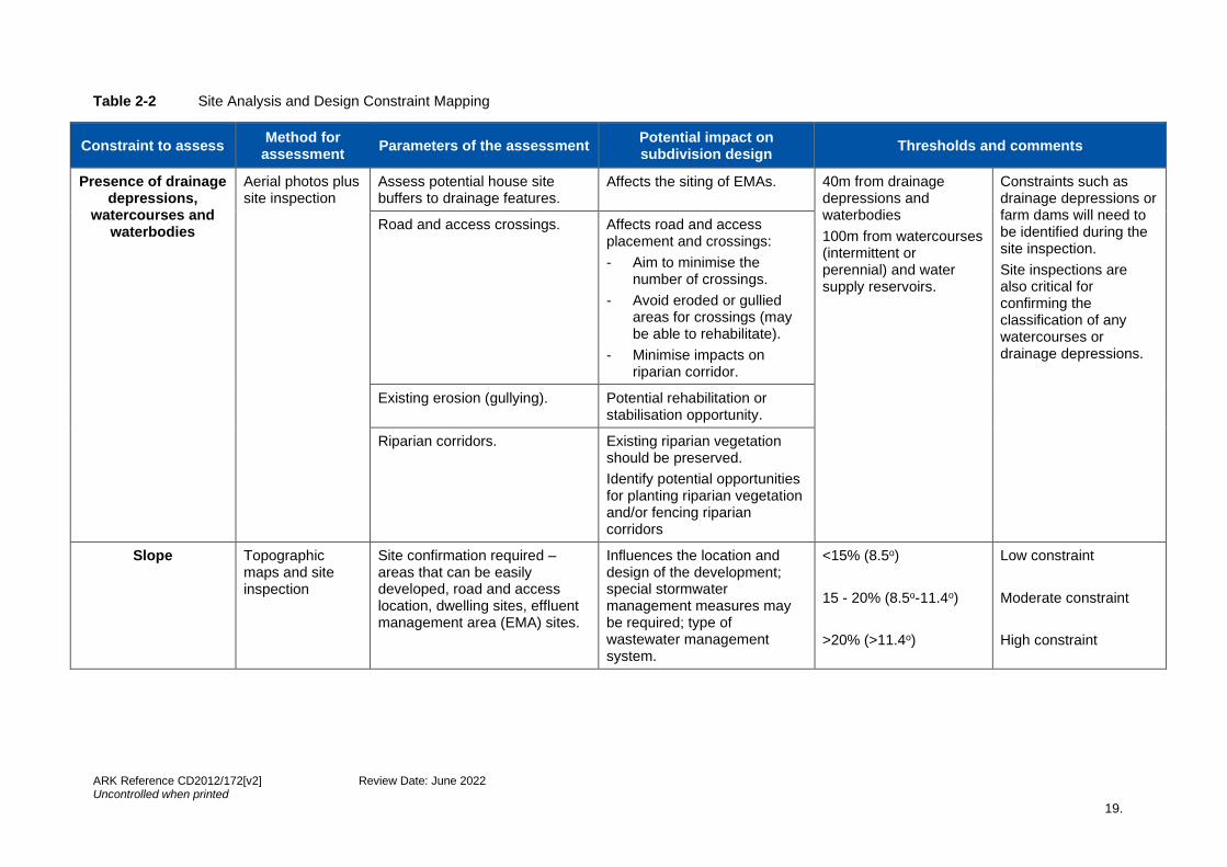
Table 2-2 Site Analysis and Design Constraint Mapping
Constraint to assess Method for
assessment Parameters of the assessment
Potential impact on subdivision design
Thresholds and comments
Presence of drainage depressions,
watercourses and waterbodies
Aerial photos plus site inspection
Assess potential house site buffers to drainage features.
Affects the siting of EMAs. 40m from drainage depressions and waterbodies
100m from watercourses (intermittent or perennial) and water supply reservoirs.
Constraints such as drainage depressions or farm dams will need to be identified during the site inspection.
Site inspections are also critical for confirming the classification of any watercourses or drainage depressions.
Road and access crossings. Affects road and access placement and crossings:
- Aim to minimise the number of crossings.
- Avoid eroded or gullied areas for crossings (may be able to rehabilitate).
- Minimise impacts on riparian corridor.
Existing erosion (gullying). Potential rehabilitation or stabilisation opportunity.
Riparian corridors. Existing riparian vegetation should be preserved.
Identify potential opportunities for planting riparian vegetation and/or fencing riparian corridors
Slope Topographic maps and site inspection
Site confirmation required – areas that can be easily developed, road and access location, dwelling sites, effluent management area (EMA) sites.
Influences the location and design of the development; special stormwater management measures may be required; type of wastewater management system.
<15% (8.5o)
15 - 20% (8.5o-11.4o)
>20% (>11.4o)
Low constraint
Moderate constraint
High constraint

ARK Reference CD2012/172[v2] Review Date: June 2022 Uncontrolled when printed
20.
Constraint to assess Method for
assessment Parameters of the assessment
Potential impact on subdivision design
Thresholds and comments
Soil depth Geotechnical site and soil assessment
AS/NZS 1547:2012
Published soil data
Assess each house site. Determine depth to rock, medium or heavy clay, or to a limiting layer (e.g. hardpan).
Influences the selection of wastewater management system and effluent management area.
Refer to DLG (1998), and the WNSW Designing and Installing On-Site Wastewater Systems (2019)
>0.9 m
0.75-0.9 m
0.4-0.75 m
0.25-0.4 m
<0.25 m
Low constraint
Low – moderate constraint
Moderate constraint
Moderate to high constraint
High constraint
Assess soil depth at potential locations for water cycle management measures (e.g. infiltration pits, swales or bioretention systems).
Shallow soils or clayey soils might not permit installation and/or effective operation of effluent management systems that rely on infiltration.
Installation of underground services.
Extensive rock outcrop or shallow soils might affect the cost or viability of installing underground services.
Dispersive soils Geotechnical site and soil assessment
AS/NZS 1547:2012.
Published soil data
Assess potential sites where construction may occur. In areas where the soils are dispersive, that part of the site is said to be highly constrained and development should be avoided.
Dispersive soils may be considered to be a constraint during their exposure and subsequent management, such as during construction works, as they become an issue for erosion and sediment control (may require the preparation of a SWMP).
The presence of dispersive soils highlights the need for Type D sediment basins for flocculation (see ‘Blue Book’) and importance of maintaining groundcover.

ARK Reference CD2012/172[v2] Review Date: June 2022 Uncontrolled when printed
21.
Constraint to assess Method for
assessment Parameters of the assessment
Potential impact on subdivision design
Thresholds and comments
Can also be considered a constraint for on-site effluent management.
Permeability Geotechnical site and soil assessment
Published data
Assess all sites during site inspection for permeable soils, especially to confirm permeability against data
Influences the location and type of wastewater EMAs.
<100 mm/day
>2500 mm/day
Low constraint area
High constraint area (for location of EMAs)
Phosphorus (P) sorption
Geotechnical site and soil assessment
Assess all sites during site inspection for soils with low phosphorus sorption capacity e.g. sandy, granitic, etc, especially to confirm against any published data
Influences the location and size of EMAs as soils with low phosphorus sorption have a reduced ability to remove phosphorus.
>100 mg/kg
<100 mg/kg
Low constraint area (for location of EMAs).
High constraint area (for location of EMAs).
Salinity Geotechnical site and soil assessment / aerial photos
Assess all sites during site inspection for saline soils, especially to confirm against any published data
Saline soils kill or inhibit the growth of vegetation, resulting in exposed soil susceptible to erosion.
No salinity
Widespread salinity
Low constraint area
High constraint area
Vegetation Aerial photos plus site inspection
Assess all sites during site inspection for vegetation, especially to confirm remnant vegetation when it is shown to be mapped on site
The clearing of vegetation should be minimised to avoid exposing soils that may be susceptible to erosion.
Clearing should be avoided on steep slopes and areas that could be groundwater recharge areas, such as rocky hilltops and ridge lines. Vegetated areas may have to be fenced off to ensure that the vegetation is protected from livestock.
Remnant vegetation 85-100%
Semi-cleared 35-85%
Essentially cleared 0-35%
High constraint
Moderate constraint
Low constraint
ARK Reference CD2012/172[v2] Review Date: June 2022 Uncontrolled when printed
22.
2.3 Site inspection
The purpose of the site inspection is to verify the information gathered in the desktop review, constraint mapping exercise and any other sources (e.g. soil landscape mapping), as well as to identify any additional issues existing on the site that may not have been identified through constraint mapping. Any additional site characteristics and features identified during the site inspection should be noted and taken into account in the design. Applicants or their consultants are not to rely on desktop review only and must demonstrate a detailed site inspection and investigation has been undertaken.
2.3.1 Identification of watercourses, drainage depressions and waterbodies
Visually inspecting the site will verify the existence of watercourses, drainage depressions and waterbodies. To assist with identification, the following definitions are provided in the Neutral or Beneficial Effect on Water Quality Assessment Guideline (WaterNSW, 2021).
• Drainage depression: A low point that carries water during rainfall events but dries out quickly once rainfall has ceased. Note that once it becomes incised or contains a gully it is considered to constitute a watercourse.
• Watercourse: means any river, creek, stream or chain of ponds, whether artificially modified or not, in which water usually flows, either continuously or intermittently, in a defined bed or channel, but does not include a waterbody (artificial).
• Waterbody (artificial): An artificial body of water, including any constructed waterway, canal, inlet, bay, channel, dam, pond, lake or artificial wetland, but does not include a dry detention basin or other stormwater management construction that is only intended to hold water intermittently.
• Waterbody (natural): A natural body of water, whether perennial or intermittent, fresh, brackish or saline, the course of which may have been artificially modified or diverted onto a new course, and includes a river, creek, stream, lake, lagoon, natural wetland, estuary, bay, inlet or tidal waters (including the sea).
While some drainage depressions and watercourses are easy to identify, others may be more difficult and may only be determined by assessment of the nature of the surrounding landform (Figures 2-1 to 2-4). For example, the larger the catchment the more likely the drainage feature should be considered as a watercourse rather than a drainage depression. Advice from WaterNSW may be necessary to correctly classify the drainage feature.

ARK Reference CD2012/172[v2] Review Date: June 2022 Uncontrolled when printed
23.
Figure 2-1 Drainage depression
Figure 2-2 Drainage depression

ARK Reference CD2012/172[v2] Review Date: June 2022 Uncontrolled when printed
24.
Figure 2-3 A watercourse with a defined channel - an eroding watercourse can contribute large amounts of sediment to the waterway and degrade water quality
Figure 2-4 A dry incised watercourse with no active erosion
ARK Reference CD2012/172[v2] Review Date: June 2022 Uncontrolled when printed
25.
2.3.2 Slope
The site inspection should confirm the desktop analysis, especially for areas with slopes over 15%. If it is confirmed that these areas do have slopes in excess of 15% then construction should be avoided if possible. If construction (e.g. roads and house sites) must occur in areas of slopes over 15%, then the methods to be used to prevent erosion occurring in the short and long term should be described. Methods to ensure sustainable effluent management should also be detailed.
2.3.3 Soils
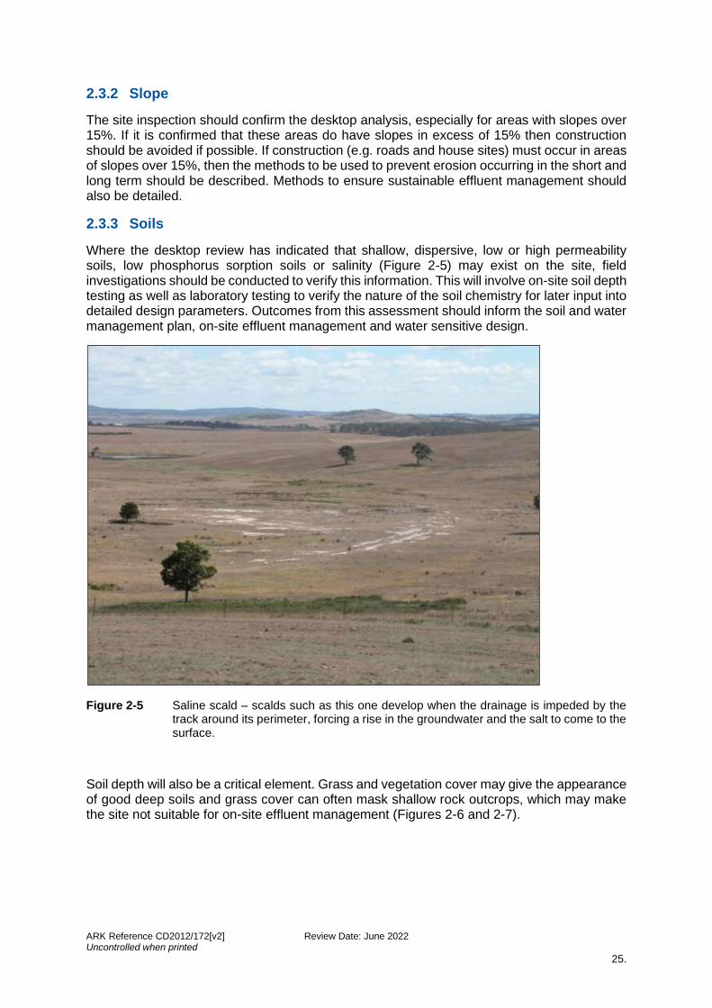
Where the desktop review has indicated that shallow, dispersive, low or high permeability soils, low phosphorus sorption soils or salinity (Figure 2-5) may exist on the site, field investigations should be conducted to verify this information. This will involve on-site soil depth testing as well as laboratory testing to verify the nature of the soil chemistry for later input into detailed design parameters. Outcomes from this assessment should inform the soil and water management plan, on-site effluent management and water sensitive design.
Figure 2-5 Saline scald – scalds such as this one develop when the drainage is impeded by the track around its perimeter, forcing a rise in the groundwater and the salt to come to the surface.
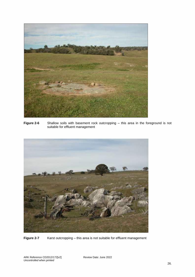
Soil depth will also be a critical element. Grass and vegetation cover may give the appearance of good deep soils and grass cover can often mask shallow rock outcrops, which may make the site not suitable for on-site effluent management (Figures 2-6 and 2-7).
ARK Reference CD2012/172[v2] Review Date: June 2022 Uncontrolled when printed
26.
Figure 2-6 Shallow soils with basement rock outcropping – this area in the foreground is not suitable for effluent management
Figure 2-7 Karst outcropping – this area is not suitable for effluent management

ARK Reference CD2012/172[v2] Review Date: June 2022 Uncontrolled when printed
27.
2.3.4 Vegetation
The assessment of vegetation requires a comprehensive analysis of all vegetation on the site, including grasses and shrubs, not just the presence of trees. This is to ensure that the water quality benefits of various vegetation types, including swamps, bushes and grasslands are considered. From a water quality perspective, the type of vegetation and the amount of groundcover is the most significant factor. It is generally accepted that groundcover of less than 70% will result in significantly increased susceptibility to sheet erosion and potential water quality impacts (DPI, 2005; Costin, 1980). It is therefore recommended to retain at least 70% groundcover across a site. Vegetation should also be protected in areas that may be groundwater recharge areas, such as rocky hilltops and ridge lines.
It should be noted that the WaterNSW does not support:
• the clearing of vegetation on steep land or other environmentally sensitive locations such as eroding areas or swamps for the purposes of boundary fencing, or
• the clearing of vegetation in saline aquifer recharge areas.
Subdivisions should be designed to minimise clearing of native vegetation, with building sites located in areas that are already cleared wherever possible. Where building sites are proposed in areas of native vegetation, note the requirements of council, the Local Land Services Act 2013, the Biodiversity Conservation Act 2016, the Environment Protection and Biodiversity Conservation Act 1999, the Environmental Planning and Assessment Act 1979 and Planning for Bushfire Protection (RFS, 2019).
An Assessment of Significance under the Environmental Planning and Assessment Act 1979 (for threatened flora and fauna species) may be required as part of the development application where there is a potential for a scheduled species and/or endangered ecological communities to occur on the site and be impacted by the proposed development. This is normally included in a broad flora and fauna assessment at the DA stage. This Assessment can also be used during the site inspection to ground-truth the vegetation detected from aerial photographs.
It is also likely that a bushfire risk assessment will need to be undertaken for all land to be subdivided that has bushland on or adjoining the area of the proposed development. While this is not a water quality issue, the management (through clearing) of the vegetation for bushfire protection can have a significant effect on water quality. As such, it is imperative that a comprehensive approach to the assessment of vegetation is undertaken, to ensure all legislation is considered.
2.3.5 Existing Degradation
Any large areas of land degradation detected in aerial photos should be inspected on-site to determine the actual type, extent and severity (Figure 2-8). The remainder of the site should also be examined for any other instances of land degradation not identified using aerial photography, and any constraints these places on the subdivision should be mapped.
Information on the extent of the degradation through delineation on the constraints map should be provided with the site analysis. If possible, the extent to which there are pollutants generated by the degraded land should be determined for use later in the NorBE test.
Areas of land degradation (e.g. Figure 2-9) should be rehabilitated as part of the subdivision to prevent sediments from reaching watercourses, and to prevent further land degradation. The requirement for rehabilitation may constrain lot layout, lot yield, lot size, and road placement, as well as building sites and effluent management areas, because any activity that may exacerbate land degradation, including erosion, should be avoided.
ARK Reference CD2012/172[v2] Review Date: June 2022 Uncontrolled when printed
28.
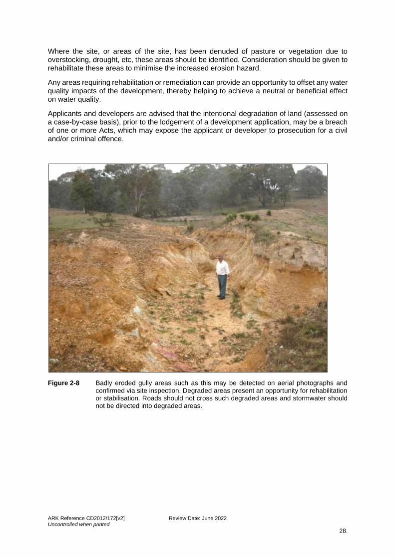
Where the site, or areas of the site, has been denuded of pasture or vegetation due to overstocking, drought, etc, these areas should be identified. Consideration should be given to rehabilitate these areas to minimise the increased erosion hazard.
Any areas requiring rehabilitation or remediation can provide an opportunity to offset any water quality impacts of the development, thereby helping to achieve a neutral or beneficial effect on water quality.
Applicants and developers are advised that the intentional degradation of land (assessed on a case-by-case basis), prior to the lodgement of a development application, may be a breach of one or more Acts, which may expose the applicant or developer to prosecution for a civil and/or criminal offence.
Figure 2-8 Badly eroded gully areas such as this may be detected on aerial photographs and confirmed via site inspection. Degraded areas present an opportunity for rehabilitation or stabilisation. Roads should not cross such degraded areas and stormwater should not be directed into degraded areas.

ARK Reference CD2012/172[v2] Review Date: June 2022 Uncontrolled when printed
29.
Longitudinal Erosion Generally associated with unprotected swale and cut-off drains associated with man-made infrastructure.
Rill Erosion The action of uncontrolled water eroding lands adjoining gullies, creek lines and the like. Poorly designed and managed ‘cut and fill batters’ are the most common source of rill erosion in rural residential subdivisions.
Sheet Flow Water flow over elevated hills/slopes where water velocity is high, particularly over poorly vegetated lands, and poor soil structure results in surface erosion.
Rocky outcrops Lack of riparian vegetation provides an opportunity for rehabilitation of degraded areas
A site inspection should be undertaken to verify information gathered in the desktop review

ARK Reference CD2012/172[v2] Review Date: June 2022 Uncontrolled when printed
30.
Figure 2-9 Site analysis issues identified by the site inspection, including opportunities for rehabilitation

ARK Reference CD2012/172[v2] Review Date: June 2022 Uncontrolled when printed
31.
2.3.6 Existing Infrastructure
The location of any existing infrastructure, including, but not limited to dwellings, farm buildings, access to the site, roads and tracks on the site, existing erosion control features or works, existing waste management measures, and the condition of each should be determined. These features may influence the subdivision layout in the design stage and can even be incorporated into a design as a feature of the development (Figure 2-10).
Figure 2-10 This existing access-way would be an asset to a subdivision because of its satisfactory cross fall and grassed drainage swale
2.3.7 OTHER
Livestock carrying capacity, i.e. the average number of animals that a pasture can be expected to support over a long term, must also be considered when identifying constraints for rural residential subdivision.
ARK Reference CD2012/172[v2] Review Date: June 2022 Uncontrolled when printed
32.
2.4 Case Study – small rural lot subdivision
The following hypothetical case study demonstrates the site analysis process for a small lot rural residential subdivision. The sub sections introduce the case study, with the applicable site conditions and constraints to be considered.
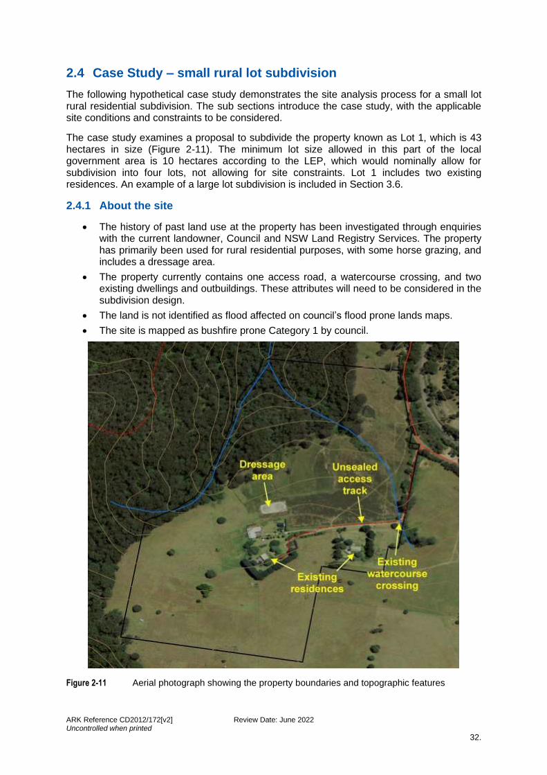
The case study examines a proposal to subdivide the property known as Lot 1, which is 43 hectares in size (Figure 2-11). The minimum lot size allowed in this part of the local government area is 10 hectares according to the LEP, which would nominally allow for subdivision into four lots, not allowing for site constraints. Lot 1 includes two existing residences. An example of a large lot subdivision is included in Section 3.6.
2.4.1 About the site
• The history of past land use at the property has been investigated through enquiries with the current landowner, Council and NSW Land Registry Services. The property has primarily been used for rural residential purposes, with some horse grazing, and includes a dressage area.
• The property currently contains one access road, a watercourse crossing, and two existing dwellings and outbuildings. These attributes will need to be considered in the subdivision design.
• The land is not identified as flood affected on council’s flood prone lands maps.
• The site is mapped as bushfire prone Category 1 by council.
Figure 2-11 Aerial photograph showing the property boundaries and topographic features
ARK Reference CD2012/172[v2] Review Date: June 2022 Uncontrolled when printed
33.
2.4.2 Site conditions and constraints to be considered
AERIAL PHOTOGRAPHY
Aerial photographs, such as in Figure 2-11, may be used in conjunction with a site inspection to identify many features of the site that may constrain the design of the subdivision, such as large areas of salinity, erosion or potentially contaminated lands, that may be caused by poor land management practices in the past, droughts or failed erosion and sediment control structures. Aerial photographs can also identify areas of remnant vegetation that should be retained.
On large properties it is particularly useful to use aerial photography to identify land degradation prior to site inspection and subdivision design, so that these areas can be targeted for rehabilitation as part of the development application and implementation process. Users should note that if there is an extended period between the date of the aerial photography and the date of subdivision design, verification of any changes to vegetation cover, access tracks, etc through a site inspection should be undertaken.
CONTAMINATED LAND
Land uses that indicate potential for contamination include sheep/cattle dips, fertiliser dumps, rural rubbish tips in gullies, and orchards and other intensive agriculture. In some areas these may also include old mining sites and tailings dams, and former industrial or commercial sites, and may involve a range of contaminants including oils, pesticides and hydrocarbons. Contaminated lands are a constraint for development and may require special treatment. Under the Contaminated Land Management Act 1997, contaminated lands can be an ongoing liability for the person causing the contamination, even after the land is sold.
WATERCOURSES AND WATERBODIES
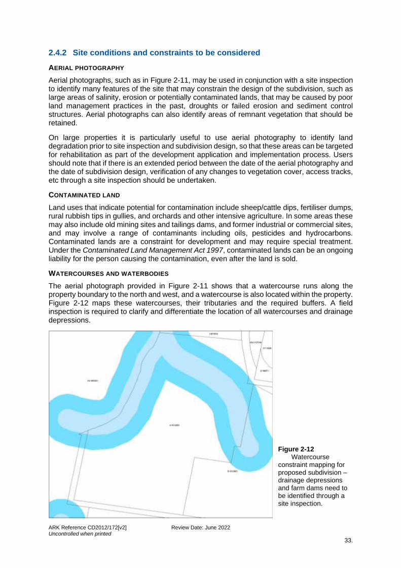
The aerial photograph provided in Figure 2-11 shows that a watercourse runs along the property boundary to the north and west, and a watercourse is also located within the property. Figure 2-12 maps these watercourses, their tributaries and the required buffers. A field inspection is required to clarify and differentiate the location of all watercourses and drainage depressions.
Figure 2-12 Watercourse constraint mapping for proposed subdivision – drainage depressions and farm dams need to be identified through a site inspection.
ARK Reference CD2012/172[v2] Review Date: June 2022 Uncontrolled when printed
34.
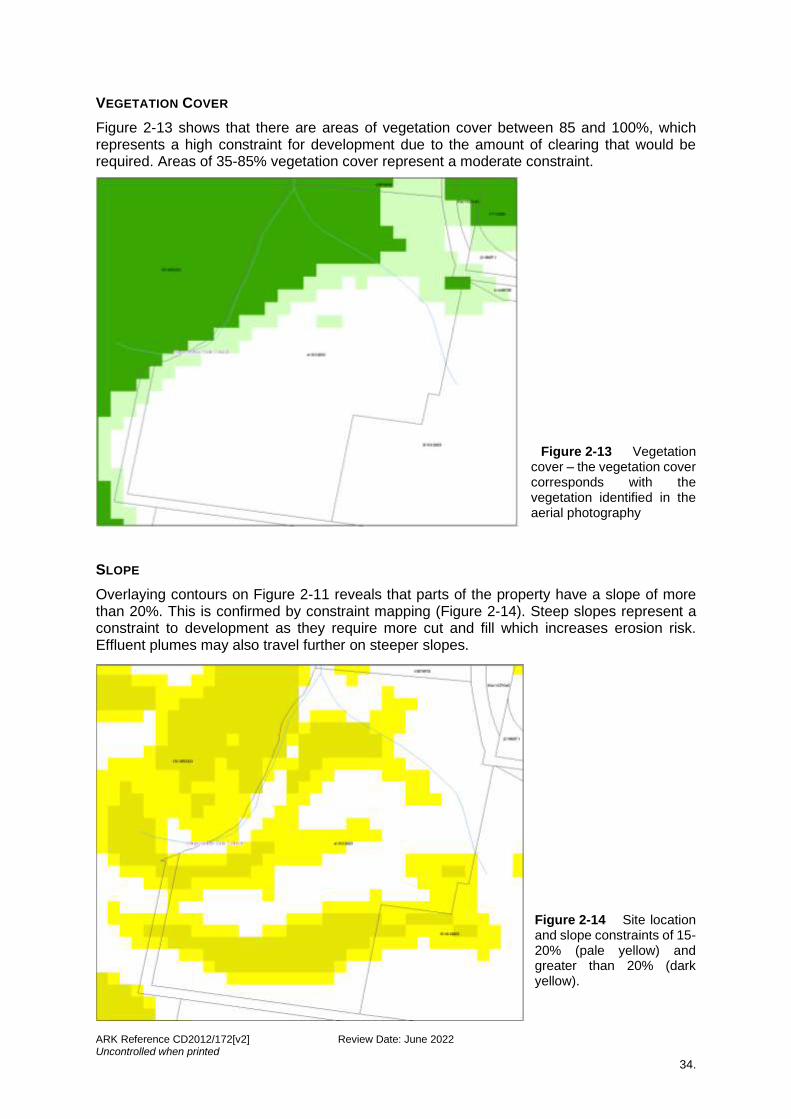
VEGETATION COVER
Figure 2-13 shows that there are areas of vegetation cover between 85 and 100%, which represents a high constraint for development due to the amount of clearing that would be required. Areas of 35-85% vegetation cover represent a moderate constraint.
Figure 2-13 Vegetation cover – the vegetation cover corresponds with the vegetation identified in the aerial photography
SLOPE
Overlaying contours on Figure 2-11 reveals that parts of the property have a slope of more than 20%. This is confirmed by constraint mapping (Figure 2-14). Steep slopes represent a constraint to development as they require more cut and fill which increases erosion risk. Effluent plumes may also travel further on steeper slopes.
Figure 2-14 Site location and slope constraints of 15-20% (pale yellow) and greater than 20% (dark yellow).
ARK Reference CD2012/172[v2] Review Date: June 2022 Uncontrolled when printed
35.
SOIL CHARACTERISTICS
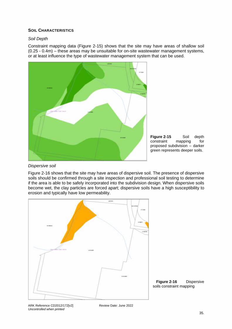
Soil Depth
Constraint mapping data (Figure 2-15) shows that the site may have areas of shallow soil (0.25 - 0.4m) – these areas may be unsuitable for on-site wastewater management systems, or at least influence the type of wastewater management system that can be used.
Figure 2-15 Soil depth constraint mapping for proposed subdivision – darker green represents deeper soils.
Dispersive soil
Figure 2-16 shows that the site may have areas of dispersive soil. The presence of dispersive soils should be confirmed through a site inspection and professional soil testing to determine if the area is able to be safely incorporated into the subdivision design. When dispersive soils become wet, the clay particles are forced apart; dispersive soils have a high susceptibility to erosion and typically have low permeability.
Figure 2-16 Dispersive soils constraint mapping

ARK Reference CD2012/172[v2] Review Date: June 2022 Uncontrolled when printed
36.
Soil permeability
Figure 2-17 shows that the property may have areas of high soil permeability (Ksat > 2,500 mm/day). These areas may be unsuitable for on-site wastewater management systems, and influence the location of effluent management areas (EMA).
Figure 2-17 Permeability – red represents possible areas of high permeability, and pink represents areas of low permeability. Low permeability soils are not indicated on this site.
Soil phosphorus sorption and salinity
Figure 2-18 shows that there is no known risk of phosphorus sorption or salinity on the property. Mean annual rainfall (>1,500 millimetres) has also been indicated on this figure.
Figure 2-18 Phosphorus sorption and salinity - these constraints were not evident at this site

ARK Reference CD2012/172[v2] Review Date: June 2022 Uncontrolled when printed
37.
2.4.3 Constraint overlay map
Constraint mapping allows various layers to be turned on or off to gain a comprehensive understanding of the overall site constraints. This information, coupled with data gathered during the desktop review and site inspection, will provide direction as to the subdivision design and layout. If the site is overly constrained it may be unsuitable for development.
A constraint overlay map involves mapping all constraints and overlaying these constraints on one image, to illustrate areas on the site that are least constrained. These ‘white’ areas become potential building sites and locations for roads and driveways in the design stage, which can be confirmed during the site inspection. It should be noted, however, poor land management practices can lead to adverse water quality impacts, even on relatively unconstrained potential building sites.
A sieve analysis was undertaken by overlaying constraint maps onto one image (Figure 2-19), for the case study site, to identify areas on the site with minimal constraints. The analysis shows that the majority of the site is constrained necessitating care in the design of the subdivision. Special construction and water sensitive design measures would need to be implemented.
Figure 2-19 Constraint overlay map showing all constraints for the case study site
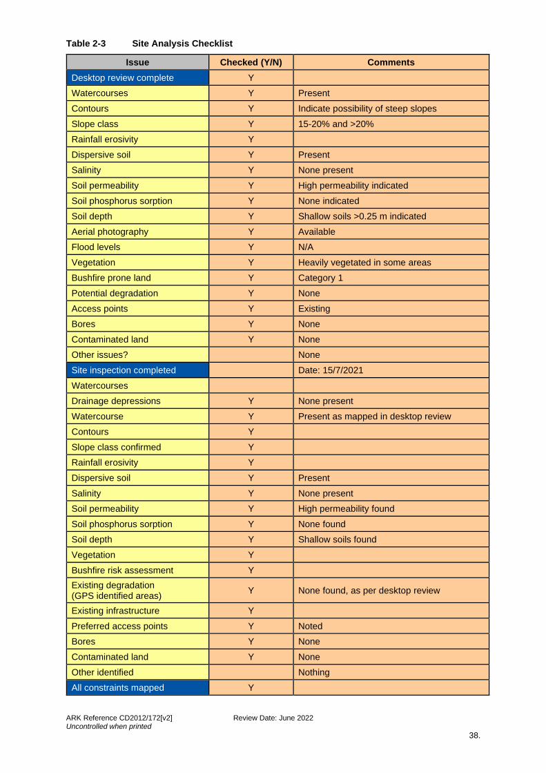
2.5 Checklist
At the conclusion of the desktop review, constraint mapping and site inspection, it is advisable to complete the checklist to ensure all relevant constraints, opportunities and issues have been identified. Table 2-3 below shows a completed checklist for the hypothetical case study.
ARK Reference CD2012/172[v2] Review Date: June 2022 Uncontrolled when printed
38.
Table 2-3 Site Analysis Checklist
Issue Checked (Y/N) Comments
Desktop review complete Y
Watercourses Y Present
Contours Y Indicate possibility of steep slopes
Slope class Y 15-20% and >20%
Rainfall erosivity Y
Dispersive soil Y Present
Salinity Y None present
Soil permeability Y High permeability indicated
Soil phosphorus sorption Y None indicated
Soil depth Y Shallow soils >0.25 m indicated
Aerial photography Y Available
Flood levels Y N/A
Vegetation Y Heavily vegetated in some areas
Bushfire prone land Y Category 1
Potential degradation Y None
Access points Y Existing
Bores Y None
Contaminated land Y None
Other issues? None
Site inspection completed Date: 15/7/2021
Watercourses
Drainage depressions Y None present
Watercourse Y Present as mapped in desktop review
Contours Y
Slope class confirmed Y
Rainfall erosivity Y
Dispersive soil Y Present
Salinity Y None present
Soil permeability Y High permeability found
Soil phosphorus sorption Y None found
Soil depth Y Shallow soils found
Vegetation Y
Bushfire risk assessment Y
Existing degradation (GPS identified areas)
Y None found, as per desktop review
Existing infrastructure Y
Preferred access points Y Noted
Bores Y None
Contaminated land Y None
Other identified Nothing
All constraints mapped Y

ARK Reference CD2012/172[v2] Review Date: June 2022 Uncontrolled when printed
39.
CHAPTER 3
SUBDIVISION DESIGN
ARK Reference CD2012/172[v2] Review Date: June 2022 Uncontrolled when printed
40.
3 SUBDIVISION DESIGN
3.1 Introduction
By its very nature, subdivision design is complex and involves a feedback process of assessing constraints, design options and potential impacts which may become constraints. Reference should be made to Appendix 1 of this Design Guide to gain an understanding of how a council and WaterNSW will be assessing the application. A clear understanding of the development assessment process should also inform the decision-making steps in a subdivision design.
This section explains how to use the information gathered in the site analysis to inform the design of the subdivision, including possible/preferred building locations, location of effluent management areas, lot layout, lot yield, lot size, and configuration, and road and dwelling access placement.
A number of key principles are introduced in this section which will assist in the design, assessment and approval of a subdivision. Firstly, the design must reflect the site conditions and constraints. It is not acceptable to design a subdivision and then justify the design through a site analysis and statement of environmental effects. There must be a clear and concise relationship between the two.
A good subdivision design will:
1. locate potential dwelling sites with appropriate effluent management areas in the most suitable constraint fee locations
2. provide vehicular access which minimises watercourse and drainage depression crossings, cut and fill and vegetation removal
3. provide complying lot sizes with boundaries in locations appropriate to the site constraints (such as watercourse, slope and vegetation)
4. achieve a proposed design that has a neutral or beneficial effect on existing water quality.
Particular emphasis should be given to how the design responds to identified site constraints including (but not limited to) watercourses and watercourse crossings, steep slopes, vegetation and groundcover, stormwater management, existing erosion control works, nearby sensitive environments and soil conditions. The design will also need to address other issues and constraints that are not directly related to the protection of water quality, including the presence of Aboriginal and European heritage, adjacent land uses, bushfire hazards, etc.
3.2 Identify potential building sites
Identification of building sites is the first step in the design process, with the road layout and subdivision pattern to follow. The number of permissible building sites is determined by the relevant local environmental plan and checking with council. Potential building sites are identified using the mapped constraints from the site analysis.
For subdivision lot sizes ranging from 2,000 square metres to 40 hectares, the potential building sites should be large enough to accommodate a dwelling plus a nominal suitable constraint free effluent management area of approximately 500 to 1,600 square metres respectively (based on the maximum area requirements for larger five to six bedroom dwellings where soils are poor with regard to depth, permeability or phosphorus sorption capacity).
ARK Reference CD2012/172[v2] Review Date: June 2022 Uncontrolled when printed
41.
It is preferable to identify building sites on areas that exclude constraints as much as possible i.e. the ‘white’ areas on the sieve analysis (Figure 3-1). This will usually result in a lower risk and a more straightforward design, assessment and approval process. If it is not possible to achieve building sites on land that is minimally constrained, then more constrained sites may need to be used. This will require more stringent design and construction measures and may result in a more complicated approval process. If a potential lot is so constrained that there is only one building site available, then the depiction of a building envelope at this location may be required on the plan of subdivision.
It should be noted that some constraints are more critical than others and may limit the potential to build, even in the absence of other constraints. For example, a site may have no other constraints identified other than a soil depth of less than 0.25 m, which would severely limit the type of effluent management system that could be used.
Further, unsewered areas within the Sydney Drinking Water Catchment, including secondary dwellings which will result in an increase to the number of bedrooms on the site or a site disturbance area of more than 250 m2 cannot pass as complying development and will require development consent (see cl 1.19(1)(j) of State Environmental Planning Policy (Exempt and Complying Development Codes) 2008).
Buildings should be sited to:
• retain and where practical, restore natural landforms, watercourses, native vegetation and other natural landscape features
• ensure that rural residential subdivision protects the biodiversity on the site by avoiding natural features and vegetated areas and where appropriate restores previously degraded habitat areas
• minimise disruption to land surfaces, natural drainage patterns and native vegetation
• incorporate existing soil and water management measures into the subdivision design.
Another important consideration is the orientation of allotments. North facing slopes are better for effluent management because the solar access maximises evapotranspiration, as well as providing solar access for the dwelling. The direction of the prevailing wind should also be considered, as wind increases evaporation.
The requirement to provide asset protection zones (APZs) between buildings and a bushfire hazard is potentially in conflict with the need to preserve vegetation for water quality benefits, as well as ecological reasons. The best way to avoid this is to place building sites in areas that are already cleared, and that will not need further clearing for APZ purposes.
This can be achieved by undertaking a preliminary bushfire assessment for the property. The vegetation for 140 m in all directions from the boundaries of the site should be examined in accordance with Planning for Bushfire Protection (RFS, 2019).
Case Study
The small rural lot subdivision hypothetical case study continues from Chapter 2 using the property and constraint mapping in Figure 2-19.
The maximum potential lot yield for this 43-hectare property under the relevant LEP is four lots, including the two existing residences. Figure 3-1 shows three new potential building sites in minimally constrained areas – one potential building site will need to be removed when the vehicular access and lot boundaries are designed (see Sections 3.4 and 3.5 below).

ARK Reference CD2012/172[v2] Review Date: June 2022 Uncontrolled when printed
42.
Figure 3-1 Identify possible minimally constrained building sites (note: the rectangles to the south identify the existing dwellings, the squares identify potential building sites). Note the requirement for a 100m buffer from watercourses.
3.3 Determine wastewater management system and location
Due to the relatively remote location of many subdivisions wastewater management will generally be provided through on-site wastewater management systems. The type of system, location within the site and ongoing management are all important considerations in the subdivision design.
Once potential building sites have been identified, the next step is to determine whether adjacent areas are suitable for effluent management. At the subdivision design stage, a determination of wastewater management systems that are unsuitable due to site and soil constraints should be made. These constraints could include lack of an appropriately sized area for effluent management, insufficient distance from waterways, steep gradient, unsuitable soil type and insufficient soil depth. A wastewater report is necessary to establish the suitability of the effluent management area, determine the area needed for treatment and the most suitable management system to use.
General objectives
• Ensure that all wastewater generated within the rural residential subdivision is managed on-site and does not contribute to water quality pollution by allocating suitable areas for wastewater (including greywater) management.
• Consider soil and landscape constraints when determining whether a site is suitable for on-site wastewater management, including permeability constraints, phosphorus sorption capacity, salinity, dispersive soils, sodicity, slope constraints, land degradation, soil depth and watercourse buffers (see Table 3-1).
ARK Reference CD2012/172[v2] Review Date: June 2022 Uncontrolled when printed
43.
• On constrained sites, an effluent management envelope of 500 to 1,600 square metres depending upon the lot size may be required to be defined on the plan of subdivision and if necessitate a restriction covenant placed on the Title for the lot (on larger and less constrained lots, it is assumed that a specific effluent management area (EMA) can be determined at the subsequent dwelling application stage). Small or heavily constrained lots may require restriction specifying a small ‘footprint’ EMA, and specific location. The aim is to ensure that each proposed lot has a suitable and adequate area for on-site effluent management for the soil conditions.
• Every lot will require an individual soil assessment and sample unless the location of any adjacent EMA is within 100 m. If the soil sample indicates that certain on-site management methods are not suitable, this should be identified in the water cycle management study.
• The wastewater effluent model (WEM) is used by WaterNSW and councils to assess whether a neutral or beneficial effect on water quality has been achieved from a wastewater management perspective. The WEM is a GIS-based, effluent plume generation modelling tool designed to support the design of on-site wastewater systems. The WEM assessment considers such constraints as slope, permeability, phosphorus sorption, rainfall, soil depth and proposed area for effluent management. More information can be found in the NorBE Assessment Guideline (WaterNSW, 2021).
• If the potential building envelope is assessed to be unsuitable for any on-site wastewater management, then that particular site should no longer be considered as a building envelope.
WaterNSW generally requires a suitable constraint free EMA of 500 to 1,600 square metres to be identified on each lot of size ranging from 2,000 square metres to 40 hectares respectively. In addition, a building envelope of notionally 45 m x 45 m is required reflecting a typical curtilage area around a rural dwelling (excluding the EMA). A small lot of less than 2,000 square metres may have difficulty accommodating contemporary building envelope and suitable constraint free effluent management area. WaterNSW may apply restrictions on the title of such small lots.
All potential building sites and associated EMAs have been located outside the appropriate buffer distance from watercourses and drainage depressions, the locations of which were confirmed during the site inspection.
RELEVANT CURRENT RECOMMENDED PRACTICES AND OTHER REFERENCES
The CRPs endorsed by WaterNSW that should be incorporated into the planning, design, construction and maintenance of on-site wastewater management systems may include:
• On-site Sewage Management for Single Households (‘the Silver Book’) (DLG, 1998).
• AS/NZS 1547:2012 On-site Domestic Wastewater Management (Standards Australia, 2012).
• Designing and Installing On-Site Wastewater Systems (WaterNSW, 2019).
APPLICATION TO RURAL RESIDENTIAL SUBDIVISIONS DESIGN
The site constraints presented in Table 3-1 need to be considered and the suggested conditions adopted. If they are not to be adopted, the proposal should be referred to WaterNSW for site specific discussions before lodgement of the development application. The listed constraints are utilised in the NorBE Assessment Tool used by councils during assessment of the proposal (see also WaterNSW, 2021).
Figure 3-2 presents an illustration of sustainable wastewater management on a rural residential lot.
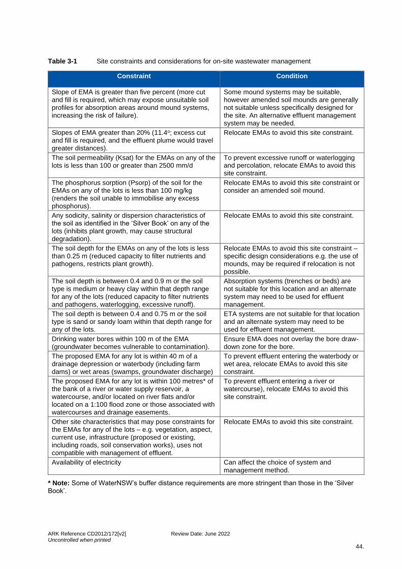
ARK Reference CD2012/172[v2] Review Date: June 2022 Uncontrolled when printed
44.
Table 3-1 Site constraints and considerations for on-site wastewater management
Constraint Condition
Slope of EMA is greater than five percent (more cut and fill is required, which may expose unsuitable soil profiles for absorption areas around mound systems, increasing the risk of failure).
Some mound systems may be suitable, however amended soil mounds are generally not suitable unless specifically designed for the site. An alternative effluent management system may be needed.
Slopes of EMA greater than 20% (11.4o; excess cut and fill is required, and the effluent plume would travel greater distances).
Relocate EMAs to avoid this site constraint.
The soil permeability (Ksat) for the EMAs on any of the lots is less than 100 or greater than 2500 mm/d
To prevent excessive runoff or waterlogging and percolation, relocate EMAs to avoid this site constraint.
The phosphorus sorption (Psorp) of the soil for the EMAs on any of the lots is less than 100 mg/kg (renders the soil unable to immobilise any excess phosphorus).
Relocate EMAs to avoid this site constraint or consider an amended soil mound.
Any sodicity, salinity or dispersion characteristics of the soil as identified in the ‘Silver Book’ on any of the lots (inhibits plant growth, may cause structural degradation).
Relocate EMAs to avoid this site constraint.
The soil depth for the EMAs on any of the lots is less than 0.25 m (reduced capacity to filter nutrients and pathogens, restricts plant growth).
Relocate EMAs to avoid this site constraint – specific design considerations e.g. the use of mounds, may be required if relocation is not possible.
The soil depth is between 0.4 and 0.9 m or the soil type is medium or heavy clay within that depth range for any of the lots (reduced capacity to filter nutrients and pathogens, waterlogging, excessive runoff).
Absorption systems (trenches or beds) are not suitable for this location and an alternate system may need to be used for effluent management.
The soil depth is between 0.4 and 0.75 m or the soil type is sand or sandy loam within that depth range for any of the lots.
ETA systems are not suitable for that location and an alternate system may need to be used for effluent management.
Drinking water bores within 100 m of the EMA (groundwater becomes vulnerable to contamination).
Ensure EMA does not overlay the bore draw-down zone for the bore.
The proposed EMA for any lot is within 40 m of a drainage depression or waterbody (including farm dams) or wet areas (swamps, groundwater discharge)
To prevent effluent entering the waterbody or wet area, relocate EMAs to avoid this site constraint.
The proposed EMA for any lot is within 100 metres* of the bank of a river or water supply reservoir, a watercourse, and/or located on river flats and/or located on a 1:100 flood zone or those associated with watercourses and drainage easements.
To prevent effluent entering a river or watercourse), relocate EMAs to avoid this site constraint.
Other site characteristics that may pose constraints for the EMAs for any of the lots – e.g. vegetation, aspect, current use, infrastructure (proposed or existing, including roads, soil conservation works), uses not compatible with management of effluent.
Relocate EMAs to avoid this site constraint.
Availability of electricity Can affect the choice of system and management method.
* Note: Some of WaterNSW’s buffer distance requirements are more stringent than those in the ‘Silver Book’.

ARK Reference CD2012/172[v2] Review Date: June 2022 Uncontrolled when printed
45.
Figure 3-2 Illustration of sustainable wastewater management on a rural residential lot
Effluent Management Area (EMA) – Absorption Trench
The soil profile, slope and on-site wastewater management system criteria are all factors that will influence the size and implementation of the EMA. These are to be installed strictly in accordance with consent conditions and the supplier’s recommendation specific to the site conditions.
Principles
• Install diversion drain and bund to upper slope to control and redirect overland flow.
• Fence the EMA and where practical integrate with boundary fences.
• Good solar access to assist evaporation.
• Bury the effluent distribution pipe from the tank to the EMA at a minimum depth of 300 mm (500 mm under an access way) in a manner that provides protection against mechanical damage or deformation.
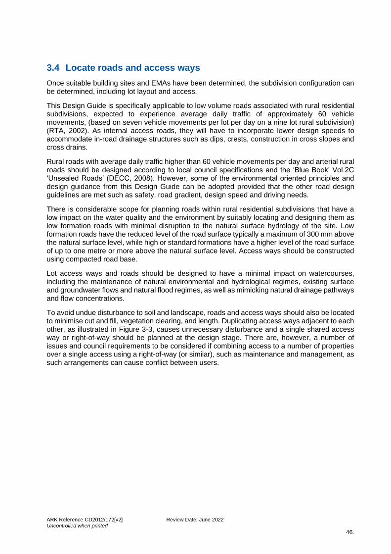
ARK Reference CD2012/172[v2] Review Date: June 2022 Uncontrolled when printed
46.
3.4 Locate roads and access ways
Once suitable building sites and EMAs have been determined, the subdivision configuration can be determined, including lot layout and access.
This Design Guide is specifically applicable to low volume roads associated with rural residential subdivisions, expected to experience average daily traffic of approximately 60 vehicle movements, (based on seven vehicle movements per lot per day on a nine lot rural subdivision) (RTA, 2002). As internal access roads, they will have to incorporate lower design speeds to accommodate in-road drainage structures such as dips, crests, construction in cross slopes and cross drains.
Rural roads with average daily traffic higher than 60 vehicle movements per day and arterial rural roads should be designed according to local council specifications and the ‘Blue Book’ Vol.2C ‘Unsealed Roads’ (DECC, 2008). However, some of the environmental oriented principles and design guidance from this Design Guide can be adopted provided that the other road design guidelines are met such as safety, road gradient, design speed and driving needs.
There is considerable scope for planning roads within rural residential subdivisions that have a low impact on the water quality and the environment by suitably locating and designing them as low formation roads with minimal disruption to the natural surface hydrology of the site. Low formation roads have the reduced level of the road surface typically a maximum of 300 mm above the natural surface level, while high or standard formations have a higher level of the road surface of up to one metre or more above the natural surface level. Access ways should be constructed using compacted road base.
Lot access ways and roads should be designed to have a minimal impact on watercourses, including the maintenance of natural environmental and hydrological regimes, existing surface and groundwater flows and natural flood regimes, as well as mimicking natural drainage pathways and flow concentrations.
To avoid undue disturbance to soil and landscape, roads and access ways should also be located to minimise cut and fill, vegetation clearing, and length. Duplicating access ways adjacent to each other, as illustrated in Figure 3-3, causes unnecessary disturbance and a single shared access way or right-of-way should be planned at the design stage. There are, however, a number of issues and council requirements to be considered if combining access to a number of properties over a single access using a right-of-way (or similar), such as maintenance and management, as such arrangements can cause conflict between users.
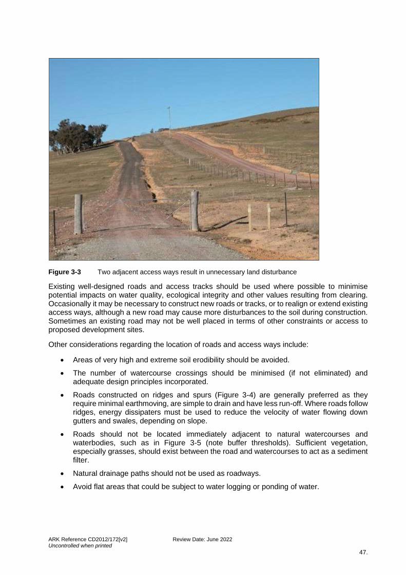
ARK Reference CD2012/172[v2] Review Date: June 2022 Uncontrolled when printed
47.
Figure 3-3 Two adjacent access ways result in unnecessary land disturbance
Existing well-designed roads and access tracks should be used where possible to minimise potential impacts on water quality, ecological integrity and other values resulting from clearing. Occasionally it may be necessary to construct new roads or tracks, or to realign or extend existing access ways, although a new road may cause more disturbances to the soil during construction. Sometimes an existing road may not be well placed in terms of other constraints or access to proposed development sites.
Other considerations regarding the location of roads and access ways include:
• Areas of very high and extreme soil erodibility should be avoided.
• The number of watercourse crossings should be minimised (if not eliminated) and adequate design principles incorporated.
• Roads constructed on ridges and spurs (Figure 3-4) are generally preferred as they require minimal earthmoving, are simple to drain and have less run-off. Where roads follow ridges, energy dissipaters must be used to reduce the velocity of water flowing down gutters and swales, depending on slope.
• Roads should not be located immediately adjacent to natural watercourses and waterbodies, such as in Figure 3-5 (note buffer thresholds). Sufficient vegetation, especially grasses, should exist between the road and watercourses to act as a sediment filter.
• Natural drainage paths should not be used as roadways.
• Avoid flat areas that could be subject to water logging or ponding of water.
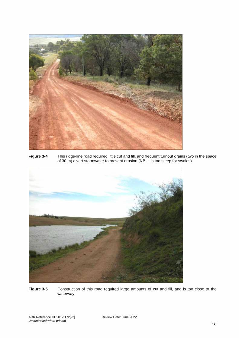
ARK Reference CD2012/172[v2] Review Date: June 2022 Uncontrolled when printed
48.
Figure 3-4 This ridge-line road required little cut and fill, and frequent turnout drains (two in the space of 30 m) divert stormwater to prevent erosion (NB: it is too steep for swales).
Figure 3-5 Construction of this road required large amounts of cut and fill, and is too close to the waterway
ARK Reference CD2012/172[v2] Review Date: June 2022 Uncontrolled when printed
49.
3.4.1 Grades
Roads and access ways with gentler gradients will result in a reduced run-off velocity. Roads with grades exceeding 21% (12o) should be avoided, as effective erosion control becomes increasingly difficult on steep slopes. New alignments should be sought, on an acceptable grade, if the road provides an integral link in the road network.
Areas of steep side or cross slopes should be avoided. Specialist engineering advice is generally required over 21% (12o) to ensure that there is adequate stabilisation of the road and batters.
Armouring of road drainage will be required for:
- grades over eight percent (4.6o) on dispersible soils, and - 10% (5.7o) on non-dispersible soils.
Gravelling and sophisticated drainage measures are required for:
- grades greater than 27% (15o) on low erodibility soils - grades greater than 21% (12o) on moderately erodible soils.
Unsealed roads should not be built on slopes exceeding 18% (10o) on highly erodible soils (the ‘Blue Book, Vol 2C, DECC, 2008).
3.4.2 Drainage
Any design of roads, rights-of-way, shared access way and access ways must allow for adequate road widths. Road widths should be capable of including road pavement and all associated drainage works. Where drainage measures and structures such as turn outs, mitres, culverts and erosion control structures are located within a private property, an easement or covenant, controls should apply to ensure ongoing maintenance and protection of these measures and structures.
The location of turn out or mitre drains to dispose of stormwater from the surface of the road should be done with care. These structures should discharge stormwater as sheet flow onto stable discharge points and not onto bare soil or areas subject to erosion. The spacing between mitre drains should be sufficient to ensure that surface flow in the table drain or edge of road does not build up sufficient energy to cause erosion (Figure 3-6).

ARK Reference CD2012/172[v2] Review Date: June 2022 Uncontrolled when printed
50.
Figure 3-6 Unsealed road showing two recently constructed mitre drains
The maximum spacing of mitre drains is given in Table 3-2, and a reasonable approach to determine the spacing is:
300 ÷ slope (expressed as a percentage)
For example, a 20% slope would require 300 ÷ 20 = 15m, resulting in a mitre drain every 15m.
Table 3-2 Recommended maximum spacing for off-road drainage structures (DECC, 2008)
Road grade Soil erodibility class
Low Moderate High
Up to 8° 70 to 90m 60 to 70m 20 to 30m
8°– 12° 60 to 70m 60 to 50m *
12°– 16° 40 to 60m * *
16°– 18° 40 to 30m * *
* Indicates that tracks of the grade specified should not normally be constructed on these soil types. Cross-banks, combined with limiting or discouraging traffic access may, however, be the best available means of erosion control on existing roads of these grades. Where tracks are constructed on slopes exceeding 120, only light and infrequent traffic should normally be permitted.
Designs should avoid the concentration of runoff flows onto adjoining land. Where necessary, place rocks, sandbags, spreader swales/banks or other protective surface to dissipate energy or disperse flow and encourage growth of vegetation at the point of water outflow from culverts and drains. Erosion and sediment control measures must be designed and implemented before work starts on the project.
Drainage works should be located to avoid the need to remove natural vegetation. Locate borrow pits, sediment ponds and stockpile sites such that native vegetation will be subjected to no or minimal impact (including siting of access routes).

ARK Reference CD2012/172[v2] Review Date: June 2022 Uncontrolled when printed
51.
Subdivisions should be designed so as not to impede the flow of groundwater in areas prone to salinity. For example, any roads traversing potentially saline areas must not impede groundwater flow and may also require special or specific engineering considerations (see ARRB 2020; Melbourne Water, 2005; DIPNR, 2003).
For constrained sites (steep slopes greater than 20%, dispersive soils and very high erosion hazards based on soil loss classes, as defined in the ‘Blue Book’ (Landcom, 2004)), a range of linings can be considered for the drain to improve erosion resistance and/or reduce flow velocity. Dense stoloniferous grasses can act to increase the surface roughness, decrease the flow rate, increase the infiltration rate, and increase the surface strength of the table drain. Where grass cover cannot be maintained or is undesirable, crushed rock can be used in selected locations where scour could be a problem. If resistance to greater flows is required rock may be grouted together (McRobert & Sheridan, 2001).
Figure 3-7 illustrates a water sensitive rural road drainage design.
3.4.3 Watercourse and drainage depression crossings
As roads approach a watercourse or drainage depression crossing, proper road drainage is critical to avoid sedimentation in watercourses. Watercourse crossings must be designed, constructed and maintained to safely handle expected vehicle loads and minimize disturbance of watercourse banks, channels and, ultimately, aquatic organisms. Poorly located or constructed watercourse crossings may cause erosion to watercourse banks and beds. When planning crossings, factors such as the watercourse bed material, size, storm frequency, flow rates, intensity of use (permanent or temporary), and the passage of fish should all be considered.
Preferred crossing types for fish passage include (in order) bridges and tunnels, arch culverts, box culverts, low level crossings such as fords and causeways, and pipe culverts and pipe causeways (Figures 3-8 and 3-9) (Fairfull, Witheridge & NSW Fisheries, 2003).
Natural Resources Access Regulator’s (NRAR’s) requirements under the Water Management Act 2000 should also be taken into account when planning and designing watercourse crossings, especially with respect to the requirement for a Controlled Activity Approval for works within 40 metres of a watercourse. More information regarding Controlled Activity Approvals can be found in Section 2.2.1 and Appendix 1 of this Design Guide. When designing watercourse crossings, the following should be considered:
• Road location design should try to minimise the number of creek crossings, since each crossing site has some impact on the environment.
• Soil stabilization practices should be used on exposed soil at watercourse crossings. Seed and mulch should be used, along with the installation of temporary sediment control structures, such as straw bales or silt fences, immediately following construction to minimise sediment entering the watercourse. These practices should be maintained until the soil is permanently stabilised. In some instances, turfing may be appropriate or the application of non-erodible materials such as concrete, bricks or gabions.
• Install watercourse crossing structures at right angles to the watercourse channel.
• Limit construction activity in the water to periods of low or normal flow. Keep use of equipment in the watercourse to a minimum.
• Construct a bridge or place fill directly over a culvert higher than the road approach to prevent surface runoff from draining onto the crossing structure and into the watercourse.
• Divert road drainage into undisturbed vegetation, so that minimal stormwater drainage from the road directly enters the watercourse. This can be achieved by constructing
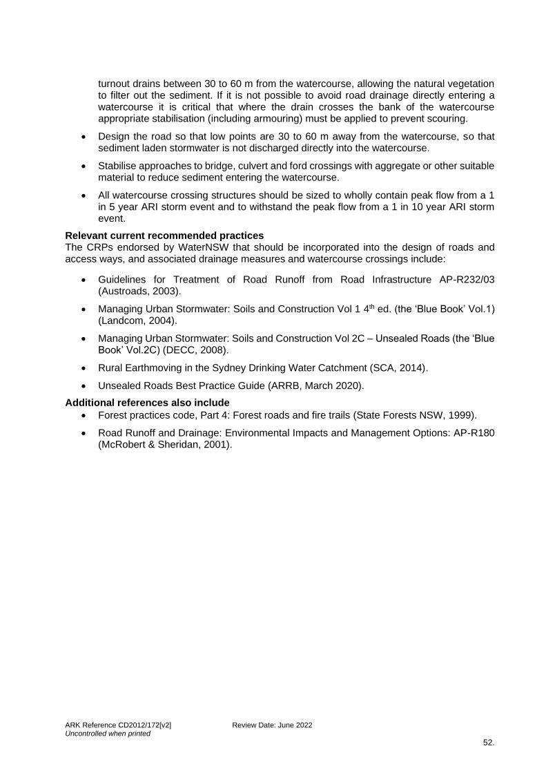
ARK Reference CD2012/172[v2] Review Date: June 2022 Uncontrolled when printed
52.
turnout drains between 30 to 60 m from the watercourse, allowing the natural vegetation to filter out the sediment. If it is not possible to avoid road drainage directly entering a watercourse it is critical that where the drain crosses the bank of the watercourse appropriate stabilisation (including armouring) must be applied to prevent scouring.
• Design the road so that low points are 30 to 60 m away from the watercourse, so that sediment laden stormwater is not discharged directly into the watercourse.
• Stabilise approaches to bridge, culvert and ford crossings with aggregate or other suitable material to reduce sediment entering the watercourse.
• All watercourse crossing structures should be sized to wholly contain peak flow from a 1 in 5 year ARI storm event and to withstand the peak flow from a 1 in 10 year ARI storm event.
Relevant current recommended practices The CRPs endorsed by WaterNSW that should be incorporated into the design of roads and access ways, and associated drainage measures and watercourse crossings include:
• Guidelines for Treatment of Road Runoff from Road Infrastructure AP-R232/03 (Austroads, 2003).
• Managing Urban Stormwater: Soils and Construction Vol 1 4th ed. (the ‘Blue Book’ Vol.1) (Landcom, 2004).
• Managing Urban Stormwater: Soils and Construction Vol 2C – Unsealed Roads (the ‘Blue Book’ Vol.2C) (DECC, 2008).
• Rural Earthmoving in the Sydney Drinking Water Catchment (SCA, 2014).
• Unsealed Roads Best Practice Guide (ARRB, March 2020).
Additional references also include
• Forest practices code, Part 4: Forest roads and fire trails (State Forests NSW, 1999).
• Road Runoff and Drainage: Environmental Impacts and Management Options: AP-R180 (McRobert & Sheridan, 2001).

ARK Reference CD2012/172[v2] Review Date: June 2022 Uncontrolled when printed
53.

ARK Reference CD2012/172[v2] Review Date: June 2022 Uncontrolled when printed
54.
Figure 3-7 Illustrations of rural subdivision vehicular access drainage designs
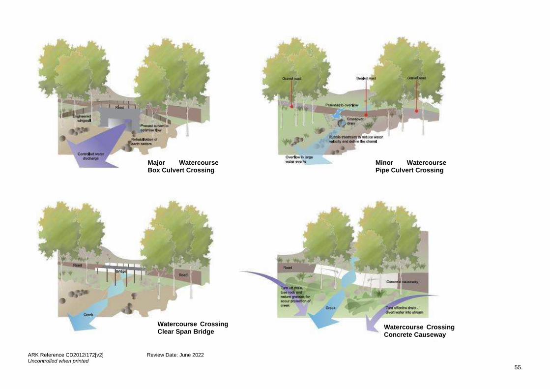
ARK Reference CD2012/172[v2] Review Date: June 2022 Uncontrolled when printed
55.
Watercourse Crossing Concrete Causeway
Watercourse Crossing Clear Span Bridge
Major Watercourse Box Culvert Crossing
Minor Watercourse Pipe Culvert Crossing

ARK Reference CD2012/172[v2] Review Date: June 2022 Uncontrolled when printed
56.
Figure 3-8 Water sensitive watercourse crossing designs
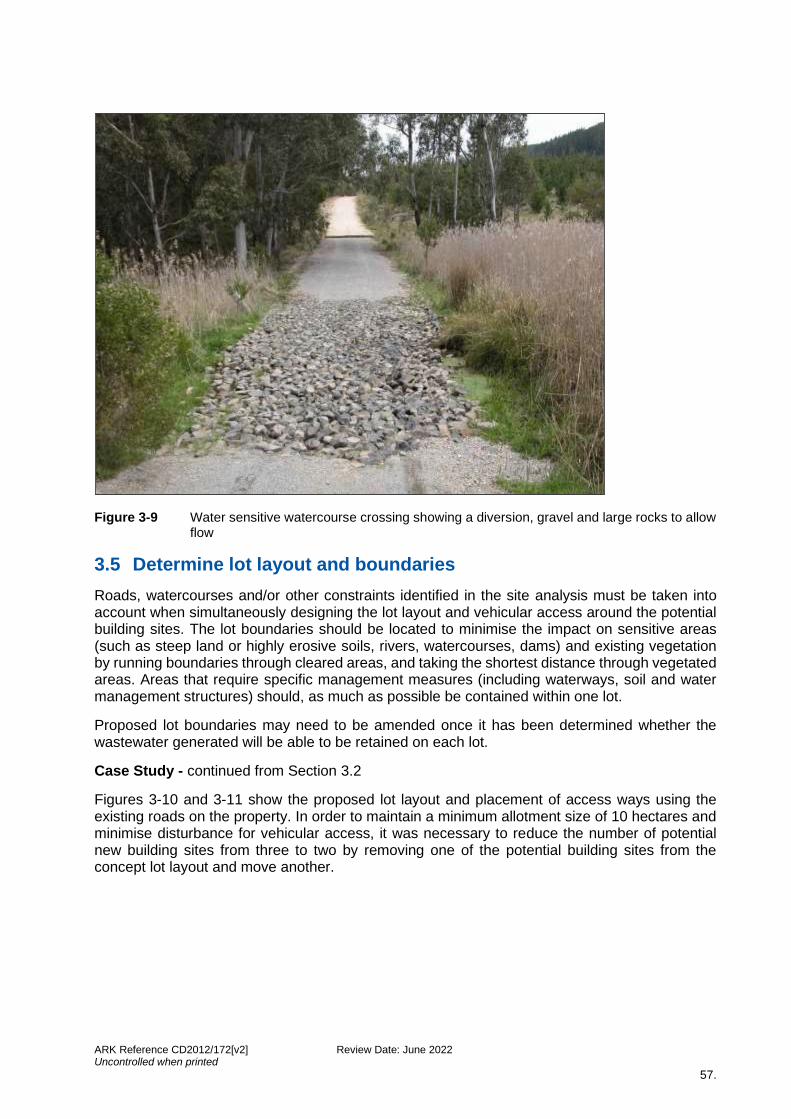
ARK Reference CD2012/172[v2] Review Date: June 2022 Uncontrolled when printed
57.
Figure 3-9 Water sensitive watercourse crossing showing a diversion, gravel and large rocks to allow flow
3.5 Determine lot layout and boundaries
Roads, watercourses and/or other constraints identified in the site analysis must be taken into account when simultaneously designing the lot layout and vehicular access around the potential building sites. The lot boundaries should be located to minimise the impact on sensitive areas (such as steep land or highly erosive soils, rivers, watercourses, dams) and existing vegetation by running boundaries through cleared areas, and taking the shortest distance through vegetated areas. Areas that require specific management measures (including waterways, soil and water management structures) should, as much as possible be contained within one lot.
Proposed lot boundaries may need to be amended once it has been determined whether the wastewater generated will be able to be retained on each lot.
Case Study - continued from Section 3.2
Figures 3-10 and 3-11 show the proposed lot layout and placement of access ways using the existing roads on the property. In order to maintain a minimum allotment size of 10 hectares and minimise disturbance for vehicular access, it was necessary to reduce the number of potential new building sites from three to two by removing one of the potential building sites from the concept lot layout and move another.

ARK Reference CD2012/172[v2] Review Date: June 2022 Uncontrolled when printed
58.
Figure 3-10 Desktop analysis – potential lot and access layout over constraint mapping.
Figure 3-11 Desktop analysis – potential lot and access layout over aerial photograph.
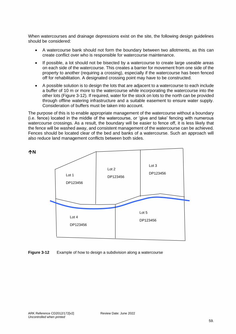
ARK Reference CD2012/172[v2] Review Date: June 2022 Uncontrolled when printed
59.
When watercourses and drainage depressions exist on the site, the following design guidelines should be considered:
• A watercourse bank should not form the boundary between two allotments, as this can create conflict over who is responsible for watercourse maintenance.
• If possible, a lot should not be bisected by a watercourse to create large useable areas on each side of the watercourse. This creates a barrier for movement from one side of the property to another (requiring a crossing), especially if the watercourse has been fenced off for rehabilitation. A designated crossing point may have to be constructed.
• A possible solution is to design the lots that are adjacent to a watercourse to each include a buffer of 10 m or more to the watercourse while incorporating the watercourse into the other lots (Figure 3-12). If required, water for the stock on lots to the north can be provided through offline watering infrastructure and a suitable easement to ensure water supply. Consideration of buffers must be taken into account.
The purpose of this is to enable appropriate management of the watercourse without a boundary (i.e. fence) located in the middle of the watercourse, or ‘give and take’ fencing with numerous watercourse crossings. As a result, the boundary will be easier to fence off, it is less likely that the fence will be washed away, and consistent management of the watercourse can be achieved. Fences should be located clear of the bed and banks of a watercourse. Such an approach will also reduce land management conflicts between both sides.
N Figure 3-12 Example of how to design a subdivision along a watercourse
Lot 1
DP123456
Lot 2
DP123456
Lot 3
DP123456
Lot 5
DP123456 Lot 4
DP123456
ARK Reference CD2012/172[v2] Review Date: June 2022 Uncontrolled when printed
60.
3.6 Locate stormwater management measures
Greater quantities and a broader variety of pollutants are generated through the replacement of vegetated ground by buildings, roads and other impervious surfaces during the process of rural residential subdivision (and the subsequent use of the land). Stormwater must be managed on-site to prevent these pollutants reaching waterbodies and watercourses. This involves a number of management practices, including:
• responsive building siting, lot layout and vehicular access, which minimises disturbance or disruption to the natural landforms, watercourses, drainage patterns and native vegetation
• minimising and controlling erosion and sedimentation impacts from the proposed subdivision during the construction stage of the development
• remediation and/or protection of degraded environments within the subdivision site such as gully erosion, native vegetation, riparian zones, salinity affected areas and stock dip sites
• adopting stormwater treatment measures to control and trap pollution in runoff before discharging outside the subdivision site. These measures could include grassed swales, constructed wetlands, ponds, rainwater tanks, filtration devices and others.
Any existing soil and water management measures on the site such as contour banks, flumes and sediment dams should be protected or restored to function as part of the stormwater management of the new subdivision.
Table 3-3 outlines the stormwater management measures that may be applicable for use in the design of a rural residential subdivision. Detailed guidance for planning, design, construction and maintenance of these stormwater management measures are provided in the CRPs listed against each management measure. The table also notes any design criteria that are specific to the use of the management measure in the drinking water catchment.
Information from the stormwater management measures design is to be incorporated into any required stormwater modelling. As a requirement for the assessment of a neutral or beneficial effect on water quality (NorBE), stormwater quality modelling must be provided for subdivision applications where impervious area, including any unsealed roads, as part of subdivision works is proposed. Note, this impervious area does not include any works required as part of future dwellings on lots. This modelling can be undertaken using Small Scale Stormwater Quality (S3QM) if impervious area is less than 2500 square metres or MUSIC (Model for Urban Stormwater Improvement Conceptualisation) for impervious area greater than 2500 square metres. MUSIC is a conceptual design tool that estimates stormwater pollutant generation from proposed land development, and the performance of stormwater treatment devices. MUSIC estimates both the short and long term effects of a wide range of stormwater management actions on the volume and quality of runoff discharging to receiving waters. To aid in assessment of stormwater pollution and its management, WaterNSW has created a MUSIC Users Guide (WaterNSW, 2019a) for use by developers and their consultants.
Stormwater quality modelling may also be required for special cases (e.g. heavily constrained sites).
Figure 3-13 presents an illustration of water sensitive stormwater management in a rural residential subdivision and Figure 3-14 presents an illustration of a constructed wetland and water quality control pond.
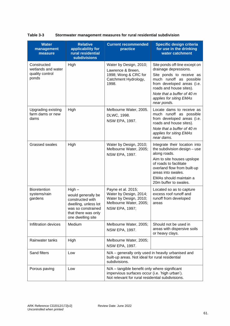
ARK Reference CD2012/172[v2] Review Date: June 2022 Uncontrolled when printed
61.
Table 3-3 Stormwater management measures for rural residential subdivision
Water management
measure
Relative applicability for rural residential
subdivisions
Current recommended practice
Specific design criteria for use in the drinking
water catchment
Constructed wetlands and water quality control ponds
High Water by Design, 2010;
Lawrence & Breen, 1998; Wong & CRC for Catchment Hydrology, 1998.
Site ponds off-line except on drainage depressions.
Site ponds to receive as much runoff as possible from developed areas (i.e. roads and house sites).
Note that a buffer of 40 m applies for siting EMAs near ponds.
Upgrading existing farm dams or new dams
High Melbourne Water, 2005.
DLWC, 1998.
NSW EPA, 1997.
Locate dams to receive as much runoff as possible from developed areas (i.e. roads and house sites).
Note that a buffer of 40 m applies for siting EMAs near dams.
Grassed swales High Water by Design, 2010; Melbourne Water, 2005;
NSW EPA, 1997.
Integrate their location into the subdivision design – use along roads.
Aim to site houses upslope of roads to facilitate overland flow from built-up areas into swales.
EMAs should maintain a 20m buffer to swales.
Bioretention systems/rain gardens
High –
would generally be constructed with dwelling, unless lot was so constrained that there was only one dwelling site
Payne et al. 2015; Water by Design, 2014; Water by Design, 2010; Melbourne Water, 2005;
NSW EPA, 1997;
Located so as to capture excess roof runoff and runoff from developed areas
Infiltration devices Medium Melbourne Water, 2005;
NSW EPA, 1997.
Should not be used in areas with dispersive soils or heavy clays.
Rainwater tanks High Melbourne Water, 2005;
NSW EPA, 1997.
Sand filters Low N/A – generally only used in heavily urbanised and built-up areas. Not ideal for rural residential subdivisions.
Porous paving Low N/A – tangible benefit only where significant impervious surfaces occur (i.e. ’high urban’). Not relevant for rural residential subdivisions.
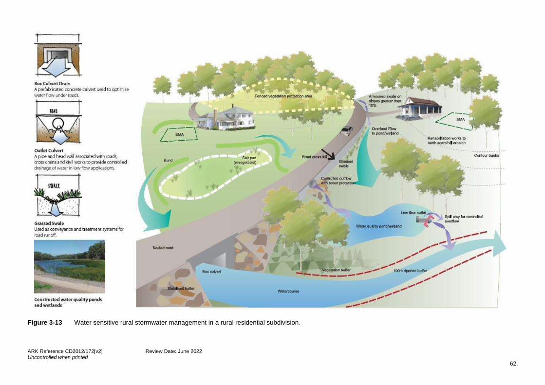
ARK Reference CD2012/172[v2] Review Date: June 2022 Uncontrolled when printed
62.
Figure 3-13 Water sensitive rural stormwater management in a rural residential subdivision.

ARK Reference CD2012/172[v2] Review Date: June 2022 Uncontrolled when printed
63.
Figure 3-14 Good design principles for constructed wetland design
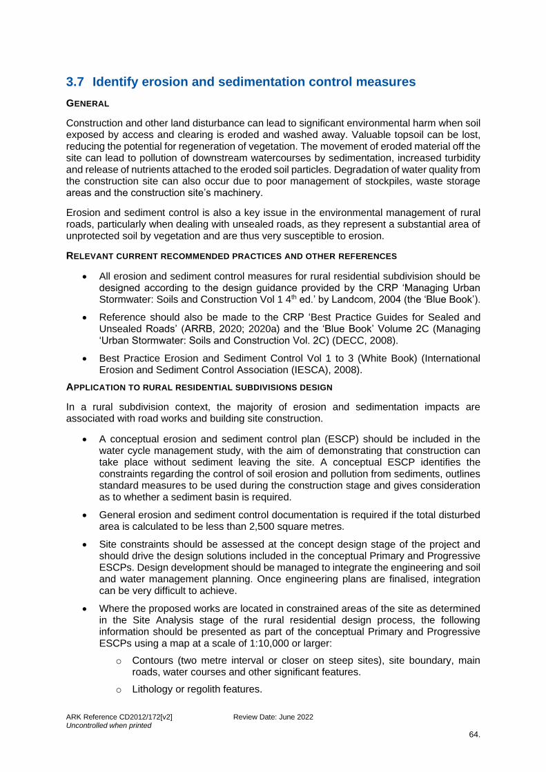
ARK Reference CD2012/172[v2] Review Date: June 2022 Uncontrolled when printed
64.
3.7 Identify erosion and sedimentation control measures
GENERAL
Construction and other land disturbance can lead to significant environmental harm when soil exposed by access and clearing is eroded and washed away. Valuable topsoil can be lost, reducing the potential for regeneration of vegetation. The movement of eroded material off the site can lead to pollution of downstream watercourses by sedimentation, increased turbidity and release of nutrients attached to the eroded soil particles. Degradation of water quality from the construction site can also occur due to poor management of stockpiles, waste storage areas and the construction site’s machinery.
Erosion and sediment control is also a key issue in the environmental management of rural roads, particularly when dealing with unsealed roads, as they represent a substantial area of unprotected soil by vegetation and are thus very susceptible to erosion.
RELEVANT CURRENT RECOMMENDED PRACTICES AND OTHER REFERENCES
• All erosion and sediment control measures for rural residential subdivision should be designed according to the design guidance provided by the CRP ‘Managing Urban Stormwater: Soils and Construction Vol 1 4th ed.’ by Landcom, 2004 (the ‘Blue Book’).
• Reference should also be made to the CRP ‘Best Practice Guides for Sealed and Unsealed Roads’ (ARRB, 2020; 2020a) and the ‘Blue Book’ Volume 2C (Managing ‘Urban Stormwater: Soils and Construction Vol. 2C) (DECC, 2008).
• Best Practice Erosion and Sediment Control Vol 1 to 3 (White Book) (International Erosion and Sediment Control Association (IESCA), 2008).
APPLICATION TO RURAL RESIDENTIAL SUBDIVISIONS DESIGN
In a rural subdivision context, the majority of erosion and sedimentation impacts are associated with road works and building site construction.
• A conceptual erosion and sediment control plan (ESCP) should be included in the water cycle management study, with the aim of demonstrating that construction can take place without sediment leaving the site. A conceptual ESCP identifies the constraints regarding the control of soil erosion and pollution from sediments, outlines standard measures to be used during the construction stage and gives consideration as to whether a sediment basin is required.
• General erosion and sediment control documentation is required if the total disturbed area is calculated to be less than 2,500 square metres.
• Site constraints should be assessed at the concept design stage of the project and should drive the design solutions included in the conceptual Primary and Progressive ESCPs. Design development should be managed to integrate the engineering and soil and water management planning. Once engineering plans are finalised, integration can be very difficult to achieve.
• Where the proposed works are located in constrained areas of the site as determined in the Site Analysis stage of the rural residential design process, the following information should be presented as part of the conceptual Primary and Progressive ESCPs using a map at a scale of 1:10,000 or larger:
o Contours (two metre interval or closer on steep sites), site boundary, main roads, water courses and other significant features.
o Lithology or regolith features.

ARK Reference CD2012/172[v2] Review Date: June 2022 Uncontrolled when printed
65.
o Slope - a minimum of three classes between 0 and 30% gradient and meeting Soil Loss Class requirements.
o Landform element from Table 2.1 of the ‘Blue Book’.
o Soil type.
o Groundwater resources and aquifer recharge areas.
o The R- and K- factors from the RUSLE, Soil Loss Class and Soil Hydrologic Group (refer to the ‘Blue Book’).
o Identification of appropriate vegetation types for rehabilitation.
o Location of dispersive soils.
3.8 Identify rehabilitation opportunities
WaterNSW considers that if a site contains degraded areas that are affecting water quality, then they should be identified for rehabilitation as part of the subdivision application. In some cases, it will be necessary to rehabilitate the degraded areas in order to achieve a neutral or beneficial effect on water quality. Table 3-4 lists the types of degraded areas where rehabilitation opportunities may exist as well as actions to address the issues.
If the site inspection reveals areas denuded of vegetation, a report from an agronomist may be required to give a methodology to rehabilitate those areas. Also, if there is limited area available for cropping or grazing due to factors such as native vegetation or slope, an agronomist’s report on the suitability of these areas for such uses may be required, as well as the stock carrying capacity of the proposed lot(s). These documents are to be made available to lot purchasers.
Degraded watercourses and other existing land degradation such as sheet erosion, gully erosion and salt scalds should be rehabilitated as part of the subdivision process. This requirement will be included in conditions of consent. If degraded areas are found, direct consultation with WaterNSW should be undertaken to determine appropriate rehabilitation actions for inclusion in the water cycle management study.
In cases where there is obvious significant existing degradation such as the gully erosion shown in Figure 3-15, the rehabilitation of the degraded environment should be considered early in site analysis and subdivision design. Other rehabilitation opportunities include remediation or protection of native vegetation and riparian zones, protection of groundwater recharge and discharge areas by fencing and rehabilitation of salinity affected areas and stock dip sites.
The general objective for rehabilitation measures design is to rectify existing situations impacting on water quality.

ARK Reference CD2012/172[v2] Review Date: June 2022 Uncontrolled when printed
66.
Table 3-4 Types of degraded area and actions to address the issue
Degradation type
Description Action
Sheet erosion The removal of a fairly uniform layer of soil from the land surface by raindrop splash and/or runoff. No perceptible channels are formed.
Vegetation with suitable species, maintain vegetation cover, and prevent compaction by fencing area off from stock.
Rill erosion (halfway between sheet and gully erosion)
The removal of soil by runoff from the land surface whereby numerous small channels, generally up to 30 cm deep, are formed. Typically occurs on recently disturbed soils.
Decrease flow velocity by
• decreasing slope length, and/or
• increasing roughness of surface.
Increase stability of surface by compaction or use of paving or riprap.
Gully erosion A complex series of processes whereby the removal of soil is characterised by large incised channels in the landscape. Such channels are generally more than 30 cm in depth. The severity of gully erosion may be recorded as minor, moderate, severe or very severe.
Depending on the severity of the erosion there are a number of options –
Direct means:
• fencing off the gully to prevent stock access
• fencing off the gully and revegetating the full extent of the gully
• reshaping the gully and surrounds to a more stable profile for gullies less than two metres deep, or
• reshaping the gully and surrounds to a more stable profile (two to five metre gully and may require permanent structures like flumes), revegetating for the full extent and fencing off.
Indirect means:
• Catchment works such as contour banks and revegetation.
Watercourse bank / bed erosion
The removal of soil by the direct action of water flow, and/or wind/wave action. Typically occurs during periods of high flow.
Determine the cause – it is better to address the cause of the problem than to repair an isolated section of channel bed or bank. There are a range of measures available, including revegetation, stabilisation and reforming ‘natural’ watercourse profile (pools and riffles). Hydraulic aspects of the watercourse need to be considered.
Mass movement A general term encompassing erosion processes in which gravity is the primary force acting to dislodge and transport land surface materials.
Evidence of prior mass movement is the best indicator that it could happen again. Due to the amalgamation of a number of factors, determine cause or likely causes (e.g. overgrazing, removal of vegetation, subsoil). The best solution will depend on the causes.
Overgrazed paddocks
Obtain an agronomist’s report to determine stock carrying capacity.
Saline / salt scalds
A bare area produced by the removal of the surface soil by wind and/or water erosion, and the
Salinity is due to either rising groundwater or impedance of subsoil groundwater flow. Determine the cause
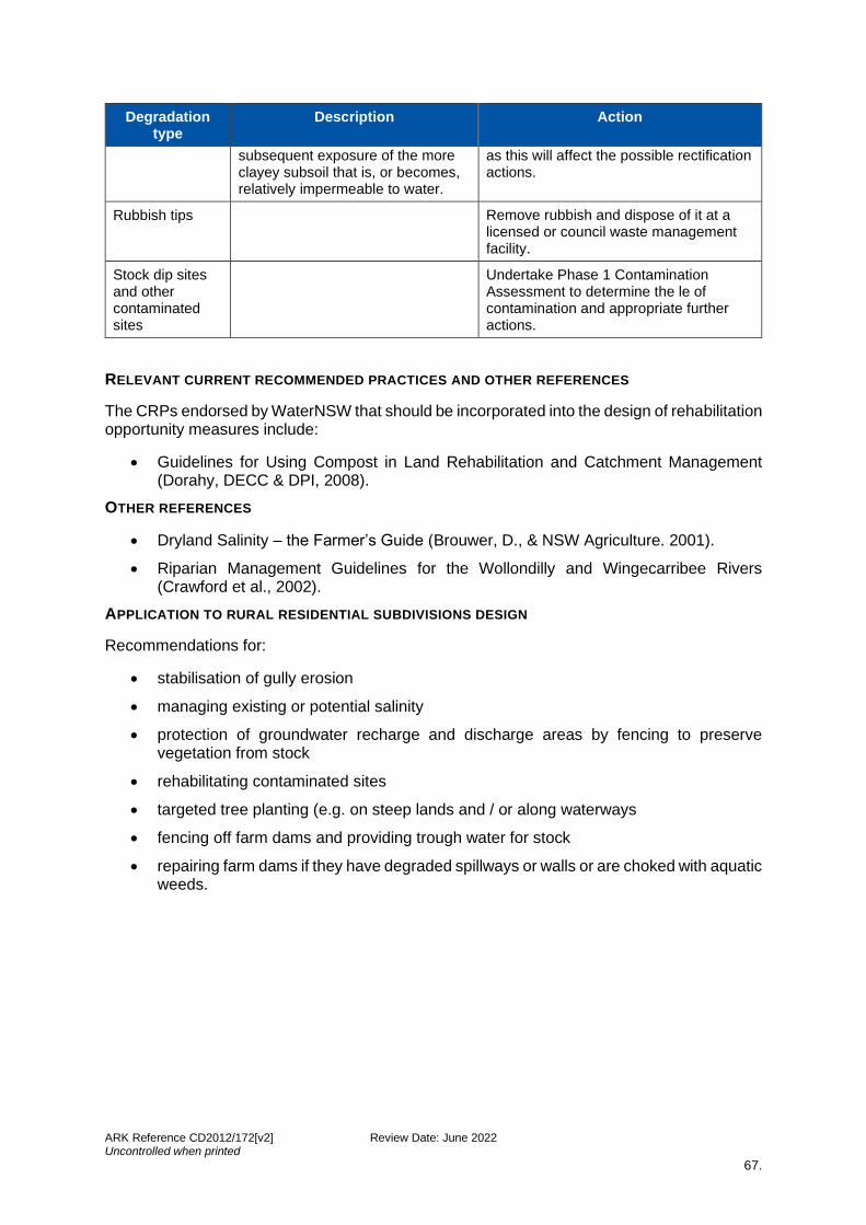
ARK Reference CD2012/172[v2] Review Date: June 2022 Uncontrolled when printed
67.
Degradation type
Description Action
subsequent exposure of the more clayey subsoil that is, or becomes, relatively impermeable to water.
as this will affect the possible rectification actions.
Rubbish tips Remove rubbish and dispose of it at a licensed or council waste management facility.
Stock dip sites and other contaminated sites
Undertake Phase 1 Contamination Assessment to determine the le of contamination and appropriate further actions.
RELEVANT CURRENT RECOMMENDED PRACTICES AND OTHER REFERENCES
The CRPs endorsed by WaterNSW that should be incorporated into the design of rehabilitation opportunity measures include:
• Guidelines for Using Compost in Land Rehabilitation and Catchment Management (Dorahy, DECC & DPI, 2008).
OTHER REFERENCES
• Dryland Salinity – the Farmer’s Guide (Brouwer, D., & NSW Agriculture. 2001).
• Riparian Management Guidelines for the Wollondilly and Wingecarribee Rivers (Crawford et al., 2002).
APPLICATION TO RURAL RESIDENTIAL SUBDIVISIONS DESIGN
Recommendations for:
• stabilisation of gully erosion
• managing existing or potential salinity
• protection of groundwater recharge and discharge areas by fencing to preserve vegetation from stock
• rehabilitating contaminated sites
• targeted tree planting (e.g. on steep lands and / or along waterways
• fencing off farm dams and providing trough water for stock
• repairing farm dams if they have degraded spillways or walls or are choked with aquatic weeds.
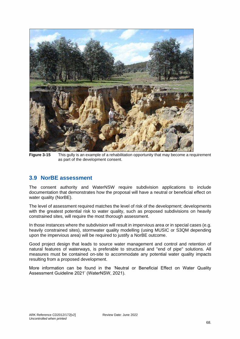
ARK Reference CD2012/172[v2] Review Date: June 2022 Uncontrolled when printed
68.
Figure 3-15 This gully is an example of a rehabilitation opportunity that may become a requirement
as part of the development consent.
3.9 NorBE assessment
The consent authority and WaterNSW require subdivision applications to include documentation that demonstrates how the proposal will have a neutral or beneficial effect on water quality (NorBE).
The level of assessment required matches the level of risk of the development; developments with the greatest potential risk to water quality, such as proposed subdivisions on heavily constrained sites, will require the most thorough assessment.
In those instances where the subdivision will result in impervious area or in special cases (e.g. heavily constrained sites), stormwater quality modelling (using MUSIC or S3QM depending upon the impervious area) will be required to justify a NorBE outcome.
Good project design that leads to source water management and control and retention of natural features of waterways, is preferable to structural and "end of pipe" solutions. All measures must be contained on-site to accommodate any potential water quality impacts resulting from a proposed development.
More information can be found in the ‘Neutral or Beneficial Effect on Water Quality Assessment Guideline 2021’ (WaterNSW, 2021).
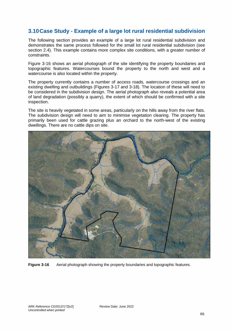
ARK Reference CD2012/172[v2] Review Date: June 2022 Uncontrolled when printed
69.
3.10 Case Study - Example of a large lot rural residential subdivision
The following section provides an example of a large lot rural residential subdivision and demonstrates the same process followed for the small lot rural residential subdivision (see section 2.4). This example contains more complex site conditions, with a greater number of constraints.
Figure 3-16 shows an aerial photograph of the site identifying the property boundaries and topographic features. Watercourses bound the property to the north and west and a watercourse is also located within the property.
The property currently contains a number of access roads, watercourse crossings and an existing dwelling and outbuildings (Figures 3-17 and 3-18). The location of these will need to be considered in the subdivision design. The aerial photograph also reveals a potential area of land degradation (possibly a quarry), the extent of which should be confirmed with a site inspection.
The site is heavily vegetated in some areas, particularly on the hills away from the river flats. The subdivision design will need to aim to minimise vegetation clearing. The property has primarily been used for cattle grazing plus an orchard to the north-west of the existing dwellings. There are no cattle dips on site.
Figure 3-16 Aerial photograph showing the property boundaries and topographic features.

ARK Reference CD2012/172[v2] Review Date: June 2022 Uncontrolled when printed
70.
Figure 3-17 Aerial photograph showing the property’s northern access features.
Figure 3-18 Aerial photograph showing the property’s southern features.
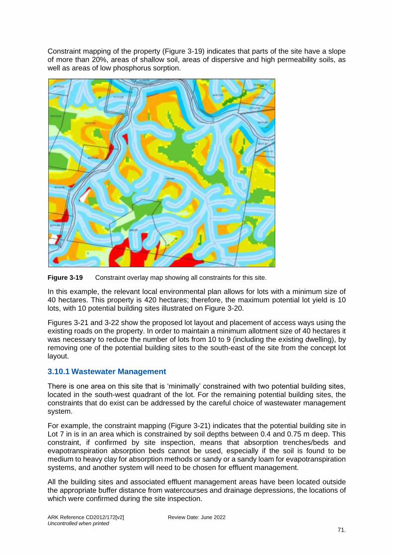
ARK Reference CD2012/172[v2] Review Date: June 2022 Uncontrolled when printed
71.
Constraint mapping of the property (Figure 3-19) indicates that parts of the site have a slope of more than 20%, areas of shallow soil, areas of dispersive and high permeability soils, as well as areas of low phosphorus sorption.
Figure 3-19 Constraint overlay map showing all constraints for this site.
In this example, the relevant local environmental plan allows for lots with a minimum size of 40 hectares. This property is 420 hectares; therefore, the maximum potential lot yield is 10 lots, with 10 potential building sites illustrated on Figure 3-20.
Figures 3-21 and 3-22 show the proposed lot layout and placement of access ways using the existing roads on the property. In order to maintain a minimum allotment size of 40 hectares it was necessary to reduce the number of lots from 10 to 9 (including the existing dwelling), by removing one of the potential building sites to the south-east of the site from the concept lot layout.
3.10.1 Wastewater Management
There is one area on this site that is ‘minimally’ constrained with two potential building sites, located in the south-west quadrant of the lot. For the remaining potential building sites, the constraints that do exist can be addressed by the careful choice of wastewater management system.
For example, the constraint mapping (Figure 3-21) indicates that the potential building site in Lot 7 in is in an area which is constrained by soil depths between 0.4 and 0.75 m deep. This constraint, if confirmed by site inspection, means that absorption trenches/beds and evapotranspiration absorption beds cannot be used, especially if the soil is found to be medium to heavy clay for absorption methods or sandy or a sandy loam for evapotranspiration systems, and another system will need to be chosen for effluent management.
All the building sites and associated effluent management areas have been located outside the appropriate buffer distance from watercourses and drainage depressions, the locations of which were confirmed during the site inspection.

ARK Reference CD2012/172[v2] Review Date: June 2022 Uncontrolled when printed
72.
Figure 3-20 Identify possible minimally constrained building sites. Note: the larger rectangle near the western boundary identifies the existing dwelling and outbuildings, the smaller black squares identify potential building sites.
3.10.2 Access
Although it is not ideal that the existing road to the north is situated so close to the river, the construction of a new road would cause unnecessary soil disturbance. Using the existing road minimises cut and fill and makes use of existing watercourse crossings. However, the existing watercourse crossings will need to be modified to minimise the localised erosion that is occurring. The existing road and crossings may also have to be upgraded to meet council requirements. This may mean that the existing locations are not suitable.
The main access road entering the site on the south-east boundary will need to be sealed to outside the property boundary as well as for its extent within the site.
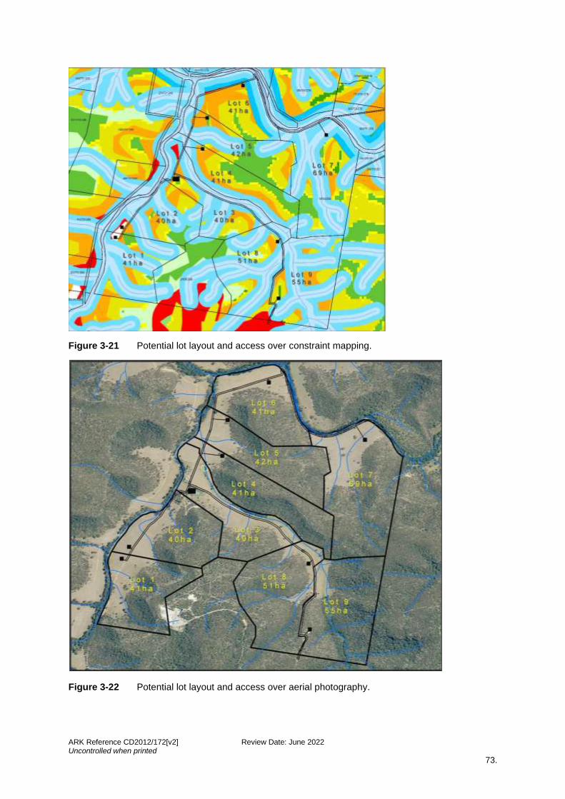
ARK Reference CD2012/172[v2] Review Date: June 2022 Uncontrolled when printed
73.
Figure 3-21 Potential lot layout and access over constraint mapping.
Figure 3-22 Potential lot layout and access over aerial photography.
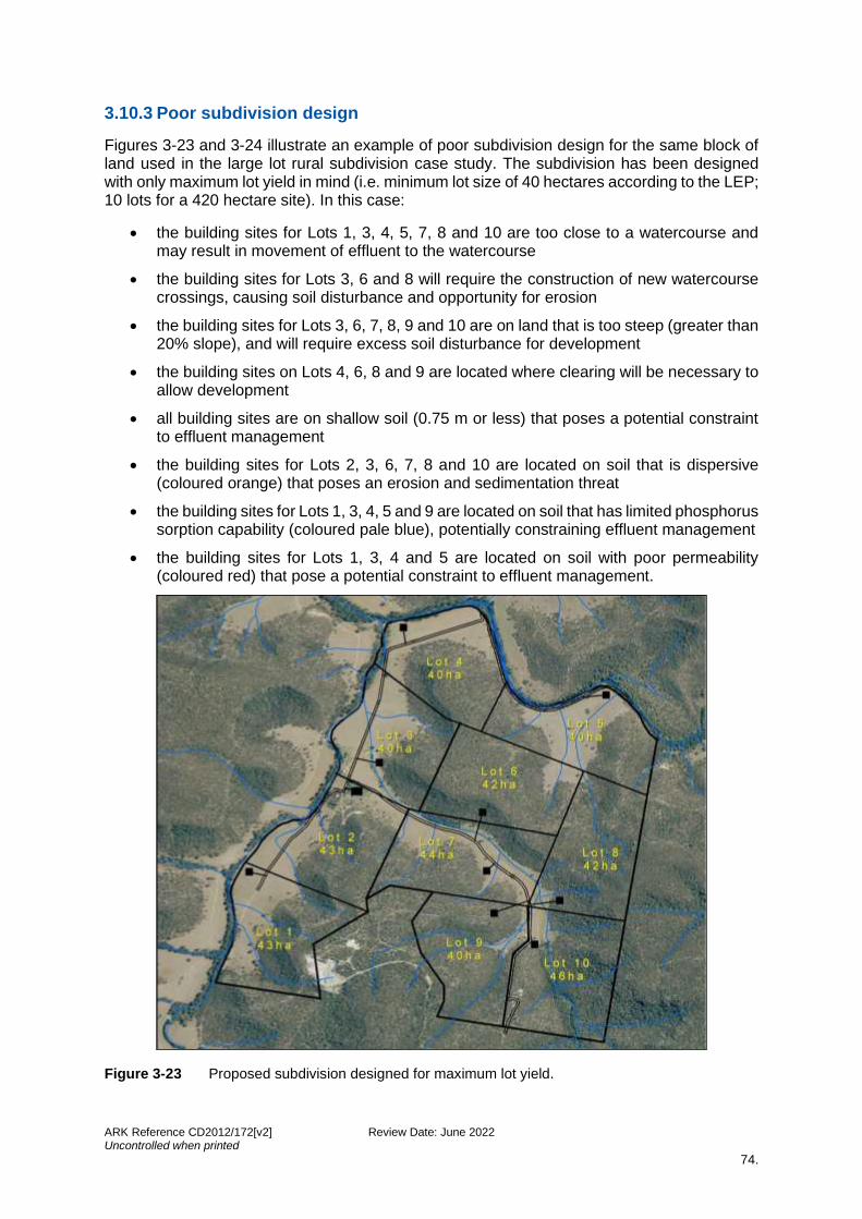
ARK Reference CD2012/172[v2] Review Date: June 2022 Uncontrolled when printed
74.
3.10.3 Poor subdivision design
Figures 3-23 and 3-24 illustrate an example of poor subdivision design for the same block of land used in the large lot rural subdivision case study. The subdivision has been designed with only maximum lot yield in mind (i.e. minimum lot size of 40 hectares according to the LEP; 10 lots for a 420 hectare site). In this case:
• the building sites for Lots 1, 3, 4, 5, 7, 8 and 10 are too close to a watercourse and may result in movement of effluent to the watercourse
• the building sites for Lots 3, 6 and 8 will require the construction of new watercourse crossings, causing soil disturbance and opportunity for erosion
• the building sites for Lots 3, 6, 7, 8, 9 and 10 are on land that is too steep (greater than 20% slope), and will require excess soil disturbance for development
• the building sites on Lots 4, 6, 8 and 9 are located where clearing will be necessary to allow development
• all building sites are on shallow soil (0.75 m or less) that poses a potential constraint to effluent management
• the building sites for Lots 2, 3, 6, 7, 8 and 10 are located on soil that is dispersive (coloured orange) that poses an erosion and sedimentation threat
• the building sites for Lots 1, 3, 4, 5 and 9 are located on soil that has limited phosphorus sorption capability (coloured pale blue), potentially constraining effluent management
• the building sites for Lots 1, 3, 4 and 5 are located on soil with poor permeability (coloured red) that pose a potential constraint to effluent management.
Figure 3-23 Proposed subdivision designed for maximum lot yield.
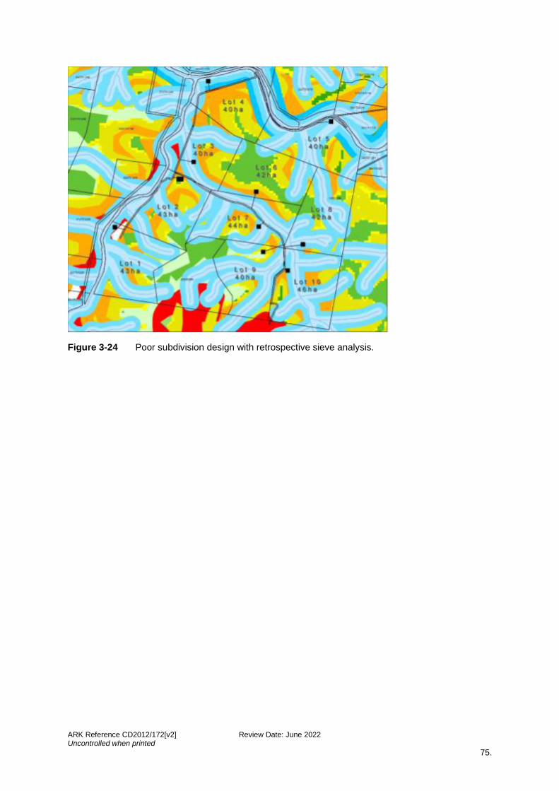
ARK Reference CD2012/172[v2] Review Date: June 2022 Uncontrolled when printed
75.
Figure 3-24 Poor subdivision design with retrospective sieve analysis.
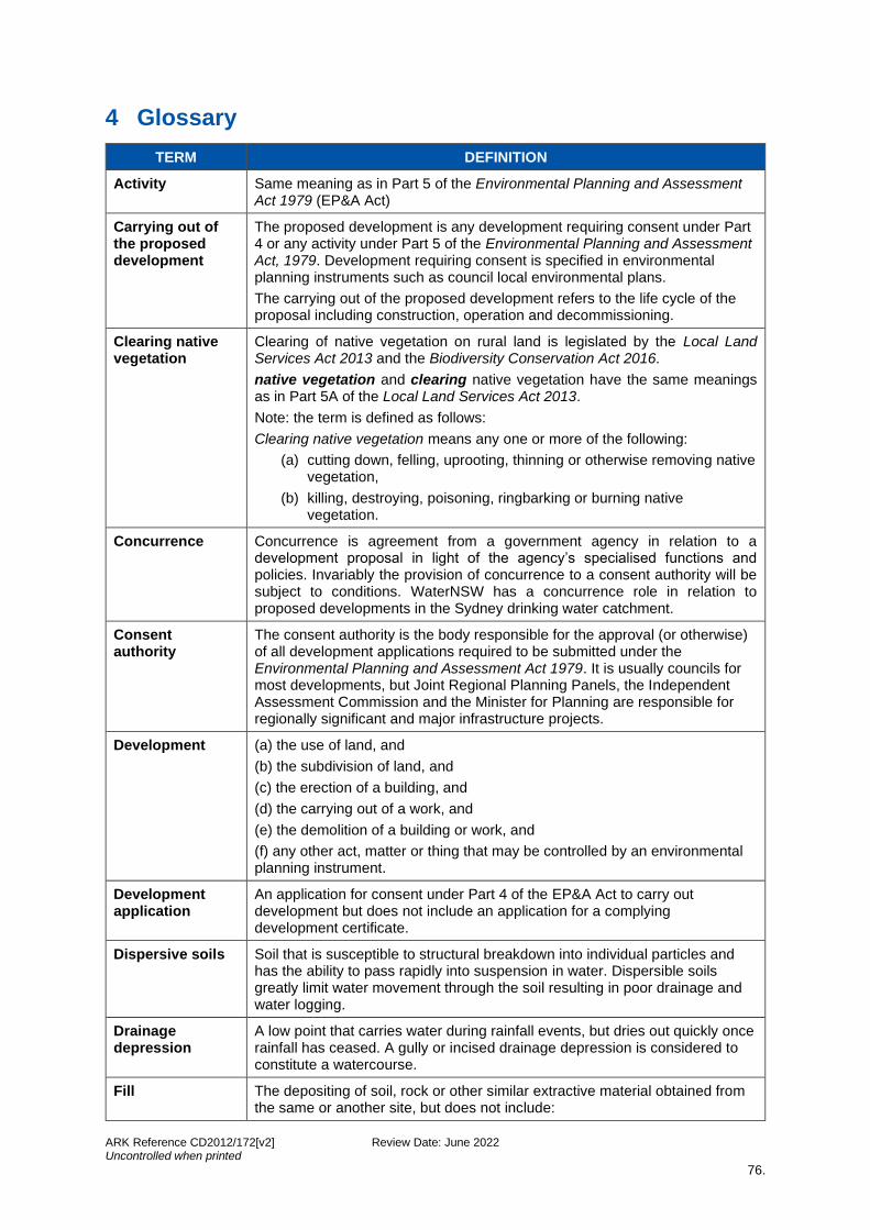
ARK Reference CD2012/172[v2] Review Date: June 2022 Uncontrolled when printed
76.
4 Glossary
TERM DEFINITION
Activity Same meaning as in Part 5 of the Environmental Planning and Assessment Act 1979 (EP&A Act)
Carrying out of the proposed development
The proposed development is any development requiring consent under Part 4 or any activity under Part 5 of the Environmental Planning and Assessment Act, 1979. Development requiring consent is specified in environmental planning instruments such as council local environmental plans.
The carrying out of the proposed development refers to the life cycle of the proposal including construction, operation and decommissioning.
Clearing native vegetation
Clearing of native vegetation on rural land is legislated by the Local Land Services Act 2013 and the Biodiversity Conservation Act 2016.
native vegetation and clearing native vegetation have the same meanings as in Part 5A of the Local Land Services Act 2013.
Note: the term is defined as follows:
Clearing native vegetation means any one or more of the following:
(a) cutting down, felling, uprooting, thinning or otherwise removing native vegetation,
(b) killing, destroying, poisoning, ringbarking or burning native vegetation.
Concurrence Concurrence is agreement from a government agency in relation to a development proposal in light of the agency’s specialised functions and policies. Invariably the provision of concurrence to a consent authority will be subject to conditions. WaterNSW has a concurrence role in relation to proposed developments in the Sydney drinking water catchment.
Consent authority
The consent authority is the body responsible for the approval (or otherwise) of all development applications required to be submitted under the Environmental Planning and Assessment Act 1979. It is usually councils for most developments, but Joint Regional Planning Panels, the Independent Assessment Commission and the Minister for Planning are responsible for regionally significant and major infrastructure projects.
Development (a) the use of land, and
(b) the subdivision of land, and
(c) the erection of a building, and
(d) the carrying out of a work, and
(e) the demolition of a building or work, and
(f) any other act, matter or thing that may be controlled by an environmental planning instrument.
Development application
An application for consent under Part 4 of the EP&A Act to carry out development but does not include an application for a complying development certificate.
Dispersive soils Soil that is susceptible to structural breakdown into individual particles and has the ability to pass rapidly into suspension in water. Dispersible soils greatly limit water movement through the soil resulting in poor drainage and water logging.
Drainage depression
A low point that carries water during rainfall events, but dries out quickly once rainfall has ceased. A gully or incised drainage depression is considered to constitute a watercourse.
Fill The depositing of soil, rock or other similar extractive material obtained from the same or another site, but does not include:
ARK Reference CD2012/172[v2] Review Date: June 2022 Uncontrolled when printed
77.
(a) the depositing of topsoil or feature rock imported to the site that is intended for use in garden landscaping, turf or garden bed establishment or top dressing of lawns and that does significantly alter the shape, natural form or drainage of the land, or
(b) a waste disposal landfill operation.
Gully erosion A form of erosion involving the formation of deep sided channels or gullies usually due to the removal of riparian vegetation.
intermittent watercourse
Having banks and beds or ponds or remaining wet for considerable periods between rainfall events and which may be characterised by supporting moisture tolerant vegetation.
permeability The permeability of a material is the speed of the water that travels through it. To be permeable, a material has to meet three conditions:
- it has to be porous,
- its openings must be large enough to let water pass through them,
and
- its openings must be well interconnected.
phosphorus sorption
The ability of soil to adsorb phosphorus.
potential bedroom
Generally, a room with a closable door, at least one window and a minimum of 8 square metres. A room in a separate building such as a studio could be considered if it has a toilet and washing facilities or close access to same. A room that could reasonably be used as a bedroom.
rainfall erosivity The potential for soil to wash off disturbed, devegetated earth into waterways during storms.
saline soil Soil that contains sufficient soluble salt to adversely affect plant growth and/or land use.
section 88 The imposition of a restriction or public positive covenant by a prescribed authority on land under the Conveyancing Act 1919.
sediment Material of varying size that is being, or has been moved from its site of origin by the action of wind, water or gravity and comes to rest on the earth’s surface, including within waterbodies.
significant cut and fill
Three metres cut and fill to be used as the upper limit.
site The site of a proposed development means the area of land described in the development application or the Part 5 assessment.
site area The area of any land on which development is carried out or is proposed to be carried out. The land may include the whole or part of one lot, or more than one lot, if they are contiguous to each other.
soil depth The vertical depth of soil from the soil surface to parent rock material.
steep Slope greater than 20% (11.4°) (for watercourses and gullies).
waterbody (artificial)
An artificial body of water, including any constructed waterway, canal, inlet, bay, channel, dam, pond, lake or artificial wetland, but does not include a dry detention basin or other stormwater management construction that is only intended to hold water intermittently.
waterbody (natural)
A natural body of water, whether perennial or intermittent, fresh, brackish or saline, the course of which may have been artificially modified or diverted onto a new course, and includes a river, creek, stream, lake, lagoon, natural wetland, estuary, bay, inlet or tidal waters (including the sea).
ARK Reference CD2012/172[v2] Review Date: June 2022 Uncontrolled when printed
78.
watercourse Means any river, creek, stream or chain of ponds, whether artificially modified or not, in which water usually flows, either continuously or intermittently, in a defined bed or channel, but does not include a waterbody (artificial).
waterway The whole or any part of a watercourse, wetland, waterbody (artificial) or waterbody (natural).
wetland Means:
(a) natural wetland, including marshes, mangroves, backwaters, billabongs, swamps, sedgelands, wet meadows or wet heathlands that form a shallow waterbody (up to two metres in depth) when inundated cyclically, intermittently or permanently with fresh, brackish or salt water, and where the inundation determines the type and productivity of the soils and the plant and animal communities, or
(b) artificial wetland, including marshes, swamps, wet meadows, sedgelands or wet heathlands that form a shallow water body (up to two metres in depth) when inundated cyclically, intermittently or permanently with water, and are constructed and vegetated with wetland plant communities.
Water Cycle Management Study (WCMS)
Water cycle management study. Components of the WCMS include:
- a conceptual SWMP or ESCP for the construction phase - an on-site effluent management plan if unsewered - water sensitive design features, and - a determination of pre- and post- development loads.
ARK Reference CD2012/172[v2] Review Date: June 2022 Uncontrolled when printed
79.
5 Acronyms
ANZECC Australian and New Zealand Environment and Conservation Council
APZ Asset protection zone
BASIX Building sustainability index
CMA Catchment management authority
CRP Current recommended practice
DA Development application
DECC Department of Environment and Climate Change
DPI Department of Primary Industries
EMA Effluent management area
EP&A Act Environmental Planning & Assessment Act 1979
ESCP Erosion and sediment control plan
GIS Geographic information systems
LPI (the former) Land and Property Information, now NSW Land Registry Services
LEP Local environmental plans
MUSIC Model for Urban Stormwater Improvement Conceptualisation
NorBE Neutral or beneficial effect on water quality
OEMP Operation Environmental Management Plan
RUSLE Revised Universal Soil Loss Equation
WNSW WaterNSW
SEPP State Environmental Planning Policy (Sydney Drinking Water Catchment) 2011
SLWCA Strategic land and water capability assessment
SWMP Soil and water management plan
WCMS Water cycle management study
WEM Wastewater effluent model
ARK Reference CD2012/172[v2] Review Date: June 2022 Uncontrolled when printed
80.
6 References
ARRB. (2020). Rural Unsealed Roads Best Practice. ARRB Transport Research, Victoria.
ARRB. (2020a). Sealed Roads Best Practice. ARRB Transport Research, Victoria.
Austroads. (2003). Guidelines for treatment of stormwater runoff from the road infrastructure. AP-R232/03. Sydney: Austroads.
Brouwer, D., & NSW Agriculture. (2001). Dryland salinity: the farmer's guide. Paterson, NSW: NSW Agriculture.
Costin, A.B. (1980). Runoff and soil and nutrient losses from an improved pasture at Ginninderra, Southern Tablelands, New South Wales. Australian Journal of Agricultural Research, 31, 533-546.
Crawford, C., Lewis, B., & Wollondilly Catchment Management Committee. (2002). Riparian management guidelines for the Wollondilly and Wingecarribee Rivers. [Goulburn NSW]: Wollondilly Catchment Management Committee.
Department of Infrastructure, Planning and Natural Resources [DIPNR]. (2003). Roads and Salinity. Sydney, NSW.
Department of Primary Industries [DPI]. (2005). Agfact P2.1.14 - Maintaining Groundcover to Reduce Erosion and Sustain Production. NSW DIPNR Gunnedah and NSW DPI, Tamworth.
Dorahy, C., & NSW Department of Environment and Climate Change [DECC] & NSW Department of Primary Industries [DPI]. (2008). Guidelines for using compost in land rehabilitation and catchment management. Dept. of Environment and Climate Change, NSW. http://www.environment.nsw.gov.au/resources/warr/2007527CompInCatchMan.pdf
Fairfull, S., Witheridge, G., & NSW Fisheries. (2003). Why do fish need to cross the road: fish passage requirements for waterway crossings. Cronulla, NSW. NSW Fisheries.
International Erosion and Sediment Control Association [IESCA]. (2008). Best Practice Erosion and Sediment Control Vol 1 to 3 (White Book). International Erosion Control Association (Australasia).
Landcom. (2004). Managing urban stormwater: soils and construction. Vol. 1, 4th Edition, (the ‘Blue Book’ Vol.1). Parramatta, NSW.
Lawrence, I. and Breen, P. (1998). Design guidelines: Stormwater pollution control ponds and wetlands. CRC for Freshwater Ecology, Canberra.
McRobert, J., & Sheridan, G. (2001). Road runoff & drainage: environmental impacts and management options: AP-R180. Sydney: Austroads Inc.
Melbourne Water. (2005). Water Sensitive Urban Design: WSUD Engineering Procedures: Stormwater. CSIRO Publishing.
NSW Department of Environment and Climate Change [DECC]. (2008). Managing urban stormwater: soils and construction. Volume 2c – unsealed roads. (the blue book Vol.2c.). Dept. of Environment and Climate Change, NSW.
NSW Department of Local Government [DLG]. (1998). Environment and health protection guidelines: on-site sewage management for single households. (‘The Silver Book’). Bankstown, NSW. Dept. of Local Government.
ARK Reference CD2012/172[v2] Review Date: June 2022 Uncontrolled when printed
81.
NSW Environment Protection Authority [EPA]. (1997). Managing urban stormwater: treatment techniques. Chatswood, New South Wales Environment Protection Authority.
NSW Rural Fire Service [RFS]. (2019). Planning for Bushfire Protection 2019. Sydney, NSW. NSW Rural Fire Service.
NSW Roads and Traffic Authority [RTA]. (2002). Guide to Traffic Generating Developments. RTA, Sydney.
Payne, E.G.I., Hatt, B.E., Deletic, A., Dobbie, M.F., McCarthy, D.T. & Chandrasena, G.I. (2015). Adoption Guidelines for Stormwater Biofiltration Systems. Melbourne, Australia: Cooperative Research Centre for Water Sensitive Cities.
Standards Australia. (2012). AS/NZS 1547:2012 – On-site Domestic Wastewater Management. Standards Australia.
State Forests of NSW. (1999). Forest Practices Code Part 4 – Forest Roads and Fire Trails. State Forests of New South Wales.
Sydney Catchment Authority [SCA]. (2014). Rural Earthmoving in the Sydney Drinking Water Catchment. Penrith, NSW.
Water by Design. (2014). Bioretention Technical Design Guidelines: Version 1.1. Brisbane, Queensland.
Water by Design. (2010). Construction and Establishment Guidelines: Swales, Bioretention Systems and Wetlands: Version 1.1. Brisbane, Queensland.
WaterNSW. (2019a). A Guide to the Use of MUSIC in Sydney’s Drinking Water Catchment. Sydney, NSW.
WaterNSW. (2019). Designing and Installing On-site Wastewater Systems. Parramatta, NSW.
WaterNSW. (2021). Neutral or Beneficial Effect on Water Quality Assessment Guideline [NorBE]. Sydney, NSW.
Wong, T. H. F. & Cooperative Research Centre for Catchment Hydrology. (1998). Managing urban stormwater using constructed wetlands. Industry Report – Report 98/7 Second Edition. Clayton, Vic: Cooperative Research Centre for Catchment Hydrology.
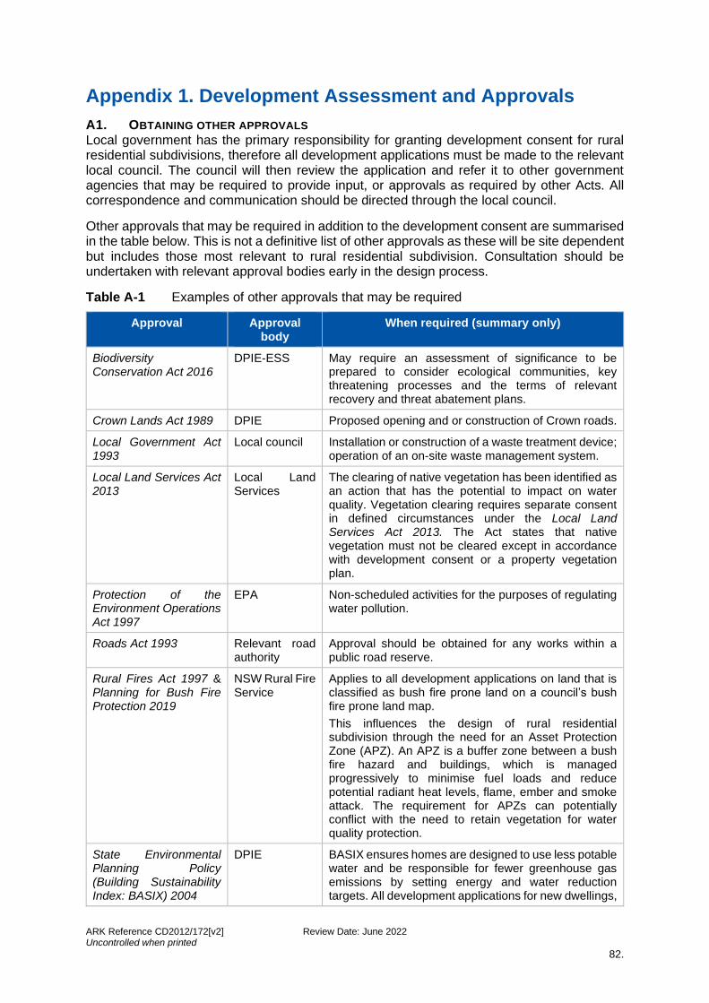
ARK Reference CD2012/172[v2] Review Date: June 2022 Uncontrolled when printed
82.
Appendix 1. Development Assessment and Approvals
A1. OBTAINING OTHER APPROVALS Local government has the primary responsibility for granting development consent for rural residential subdivisions, therefore all development applications must be made to the relevant local council. The council will then review the application and refer it to other government agencies that may be required to provide input, or approvals as required by other Acts. All correspondence and communication should be directed through the local council.
Other approvals that may be required in addition to the development consent are summarised in the table below. This is not a definitive list of other approvals as these will be site dependent but includes those most relevant to rural residential subdivision. Consultation should be undertaken with relevant approval bodies early in the design process.
Table A-1 Examples of other approvals that may be required
Approval Approval body
When required (summary only)
Biodiversity Conservation Act 2016
DPIE-ESS May require an assessment of significance to be prepared to consider ecological communities, key threatening processes and the terms of relevant recovery and threat abatement plans.
Crown Lands Act 1989 DPIE Proposed opening and or construction of Crown roads.
Local Government Act 1993
Local council Installation or construction of a waste treatment device; operation of an on-site waste management system.
Local Land Services Act 2013
Local Land Services
The clearing of native vegetation has been identified as an action that has the potential to impact on water quality. Vegetation clearing requires separate consent in defined circumstances under the Local Land Services Act 2013. The Act states that native vegetation must not be cleared except in accordance with development consent or a property vegetation plan.
Protection of the Environment Operations Act 1997
EPA Non-scheduled activities for the purposes of regulating water pollution.
Roads Act 1993 Relevant road authority
Approval should be obtained for any works within a public road reserve.
Rural Fires Act 1997 & Planning for Bush Fire Protection 2019
NSW Rural Fire Service
Applies to all development applications on land that is classified as bush fire prone land on a council’s bush fire prone land map.
This influences the design of rural residential subdivision through the need for an Asset Protection Zone (APZ). An APZ is a buffer zone between a bush fire hazard and buildings, which is managed progressively to minimise fuel loads and reduce potential radiant heat levels, flame, ember and smoke attack. The requirement for APZs can potentially conflict with the need to retain vegetation for water quality protection.
State Environmental Planning Policy (Building Sustainability Index: BASIX) 2004
DPIE BASIX ensures homes are designed to use less potable water and be responsible for fewer greenhouse gas emissions by setting energy and water reduction targets. All development applications for new dwellings,
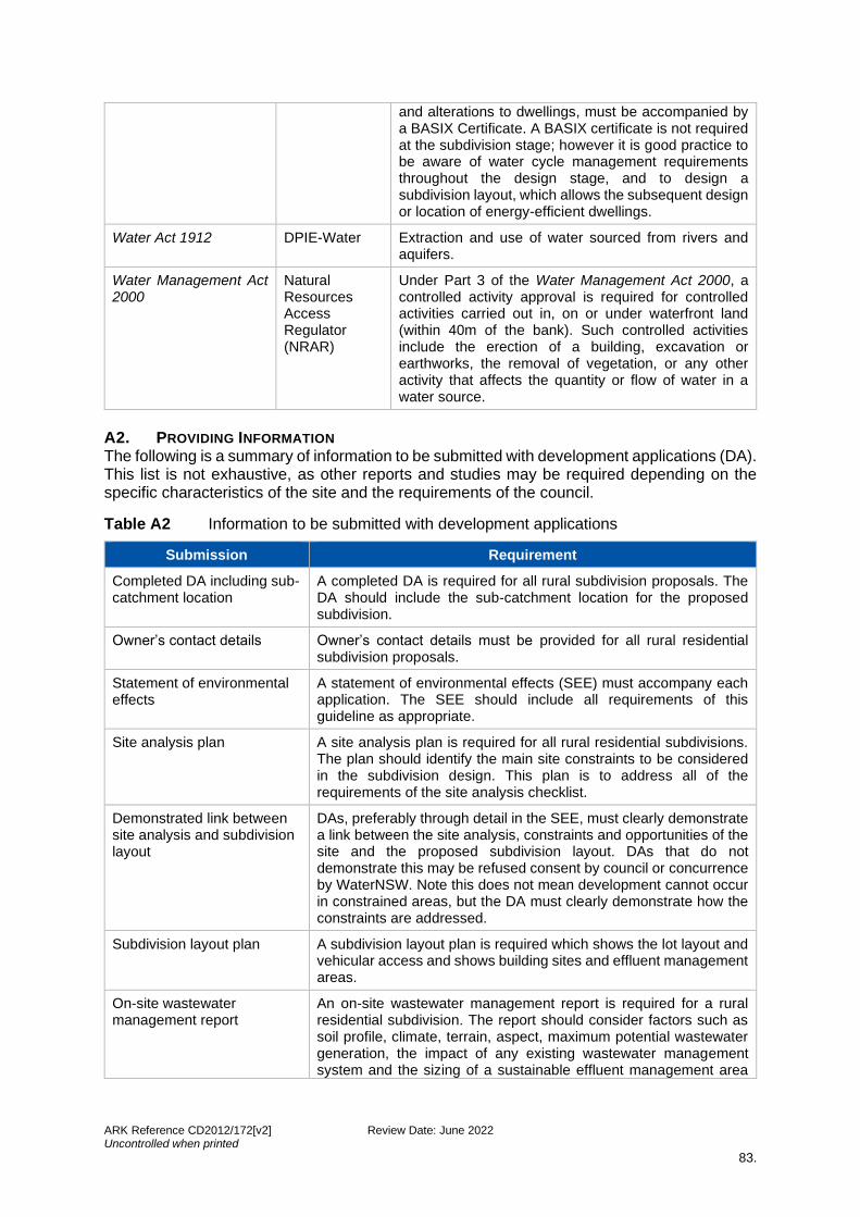
ARK Reference CD2012/172[v2] Review Date: June 2022 Uncontrolled when printed
83.
and alterations to dwellings, must be accompanied by a BASIX Certificate. A BASIX certificate is not required at the subdivision stage; however it is good practice to be aware of water cycle management requirements throughout the design stage, and to design a subdivision layout, which allows the subsequent design or location of energy-efficient dwellings.
Water Act 1912 DPIE-Water Extraction and use of water sourced from rivers and aquifers.
Water Management Act 2000
Natural Resources Access Regulator (NRAR)
Under Part 3 of the Water Management Act 2000, a controlled activity approval is required for controlled activities carried out in, on or under waterfront land (within 40m of the bank). Such controlled activities include the erection of a building, excavation or earthworks, the removal of vegetation, or any other activity that affects the quantity or flow of water in a water source.
A2. PROVIDING INFORMATION The following is a summary of information to be submitted with development applications (DA). This list is not exhaustive, as other reports and studies may be required depending on the specific characteristics of the site and the requirements of the council.
Table A2 Information to be submitted with development applications
Submission Requirement
Completed DA including sub-catchment location
A completed DA is required for all rural subdivision proposals. The DA should include the sub-catchment location for the proposed subdivision.
Owner’s contact details Owner’s contact details must be provided for all rural residential subdivision proposals.
Statement of environmental effects
A statement of environmental effects (SEE) must accompany each application. The SEE should include all requirements of this guideline as appropriate.
Site analysis plan A site analysis plan is required for all rural residential subdivisions. The plan should identify the main site constraints to be considered in the subdivision design. This plan is to address all of the requirements of the site analysis checklist.
Demonstrated link between site analysis and subdivision layout
DAs, preferably through detail in the SEE, must clearly demonstrate a link between the site analysis, constraints and opportunities of the site and the proposed subdivision layout. DAs that do not demonstrate this may be refused consent by council or concurrence by WaterNSW. Note this does not mean development cannot occur in constrained areas, but the DA must clearly demonstrate how the constraints are addressed.
Subdivision layout plan A subdivision layout plan is required which shows the lot layout and vehicular access and shows building sites and effluent management areas.
On-site wastewater management report
An on-site wastewater management report is required for a rural residential subdivision. The report should consider factors such as soil profile, climate, terrain, aspect, maximum potential wastewater generation, the impact of any existing wastewater management system and the sizing of a sustainable effluent management area

ARK Reference CD2012/172[v2] Review Date: June 2022 Uncontrolled when printed
84.
Submission Requirement
(EMA). As a general rule, one soil profile per lot is required unless documented justification is provided for less samples.
Water Cycle Management Study (WCMS)
All development applications in the Sydney drinking water catchment should include a water cycle management study (WCMS) or equivalent information depending upon the development, to help
council and WaterNSW assess whether the development will have a NorBE on water quality. The study must include information, reports and modelling appropriate to the type of development and the risks the development has for water quality. Higher risk proposals require more in-depth studies. The WCMS must also include information about erosion and sediment control, and detailed information and reports about stormwater management and wastewater management in any unsewered area.
Erosion & Sediment Control Plan (ESCP)
A plan that specifies proposed erosion and sediment control measures for the subdivision is required for all rural residential subdivisions with a construction area less than 2,500 square metres.
Primary and Progressive ESCPs
Erosion and sediment control plans that relate to road construction. The Primary ESCP would contain standard procedures and drawings to be used on a site and is supplemented by Progressive ESCPs. Progressive ESCPs are prepared for specific locations, such as areas of high erosion hazard, and as required during the construction process e.g. clearing phase to construction phase.
Soil & Water Management Plan (SWMP)
A soil and water management plan is required for all rural residential subdivision with a construction or impervious area greater than 2,500 square metres which specifies the soil and water management measures being incorporated on site.
Stormwater quality modelling Stormwater quality modelling data must be provided for residential subdivision applications where impervious area is created as part of subdivision works or special cases (e.g. heavily constrained sites).
Use Small Scale Stormwater Quality (S3QM) if impervious area is less than 2500 square metres or MUSIC (Model for Urban Stormwater Improvement Conceptualisation) for impervious area greater than 2500 square metres.
A3. RURAL RESIDENTIAL DESIGN GUIDE REQUIREMENTS As discussed previously, this Design Guide has been prepared to assist developers to prepare subdivisions to meet the requirements of the NorBE test. The consent authority should assess how developers have applied this Design Guide in developing their rural residential subdivision proposal, as this will help inform their NorBE assessment process. In order to assist consent authorities in this process, the following checklist has been included (Table A3).
Note: if the development proposal is referred to WaterNSW for concurrence, a copy of the completed checklist should be provided with the DA documentation.
As a first step, consent authorities must determine if all the required documentation/ information has been included in the application. The assessment of rural residential subdivision is dependent on the provision of appropriate information. Secondly, the consent authority or concurrence agency must decide if the site analysis was completed adequately and undertaken in accordance with this design guide. Site Analysis is a critical element of good subdivision design and it should determine site opportunities and constraints in relation to water quality impacts. The consent authority or concurrence agency will review the information provided and ensure the data is consistent with published data. Lastly, the consent

ARK Reference CD2012/172[v2] Review Date: June 2022 Uncontrolled when printed
85.
authority or concurrence agency will confirm if the subdivision design has considered all the possible site constraints
It is essential that the final subdivision design responds to the site analysis. The consent authority should ensure that all issues have been addressed and that the design reflects the site analysis.
Table A3 Rural Residential Subdivision Assessment Checklist
Information required Information supplied (Y/N)
Completed DA including sub-catchment location
Owner’s contact details
Subdivision layout plan
Water cycle management study or equivalent, including (where required):
- on-site wastewater management report
- NorBE assessment
- a conceptual SWMP or ESCP for the construction phase
- an on-site effluent management report if unsewered
- MUSIC modelling outputs (including a determination of pre- and post-development loads) or small-scale stormwater quality modelling outputs (S3QM)
- existing and proposed water sensitive design features, including erosion control works such as contour banks, flumes and revegetation, and
- an Operational Environmental Management Plan (OEMP)
Site Analysis review Yes No Comment
Have all the constraints been mapped?
Has a site inspection been completed? (provide date)
Has a site inspection confirmed mapped constraints?
Subdivision design Yes No Comment
The subdivision design complies with the Design Guide
Justification for all design outcomes included
Potential building sites identified
Effluent management areas shown
Suitable vehicular access included in design
Cut & fill minimised
Watercourse crossings minimised
Property boundary alignment minimises impact (e.g. minimal vegetation clearing along fence lines)
Water sensitive design measures included

ARK Reference CD2012/172[v2] Review Date: June 2022 Uncontrolled when printed
86.
WaterNSW Head Office Level 14, 169 Macquarie Street Parramatta NSW 2124 Phone: 1300 662 077 Email: [email protected] Web: www.waternsw.com.au
Mailing address PO Box 398 Parramatta NSW 2124 Office hours: 9.00am to 5.00pm Monday to Friday