waste heat recovery from packaged incinerators* heat recovery from packaged incinerators· robert e....
TRANSCRIPT

-Waste Heat Recovery from Packaged Incinerators·
ROBERT E. McREE
INTRODUCTION
Although heat recovery has long been carried out in large municipal type incinerators, recovery of heat from packaged incineration equipment has been essentially nonexistent until probably the past year. It has generally been thought that heat recovery of this sort would probably not be justified until some future time as fuel costs rise. [1] There can be no doubt that this time is now upon us.
Some manufacturers have made minor attempts at utilizing energy economy in the form of combustion air preheaters and carbon monoxide and pyrolysis gas recycling along with combustion air to effect some reduction in auxiliary fuel usage. All of these attempts, however, have been negligible when compared to the total energy available from the flue gases of the larger packaged type incinerators. It is the writer's objective in this paper to discuss some of the design problems unique to heat recovery on packaged incinerators and the economic justification of such recovery. For the purpose of this paper; packaged incinerators will be defmed as those units with burning capacities ranging from 1000 to 2500 pounds per hour (based on Type 1 waste). Although smaller units exist, they will not be considered here due to their low heat recovery capabilities.
An exanlination of the following areas will be made in this evaluation:
1. Characteristics of flue gases 2. Methods of incinerator charging 3. Types of heat recovery equipment 4. Heat recovery capabilities 5. Typical installation 6. Cost data and economic justification 7. Conclusions
CHARACTERISTICS OF FLUE GASES
The characteristics of the flue gases from an incinerator directly affect the design of any waste heat recqvery unit. The most important of these characteristics include the temperature, constancy of flow, particulate loading of the gas, corrosion properties and the relative volatility of the waste. Unlike large stationary boilers generating steam from one particular fuel such as coal, gas or even a blended waste such as that from a municipality, packaged type incinerators are very often called upon to dispose of a wide range of specialty type wastes ranging from a Type 4 pathological waste having a heat of combus-tion of only 1000 Btu per pound to extremely high heat content materials such as pure polyethylene with a heat of combustion of 22000 Btu per.pound. It should be added that either of these extremes can be handled in essentially pure forms in packaged controlled air units without the need for dilution with other waste material to avoid excessive stack emissions as is usually
Presented before the ASME Incinerator Division, Arlington, Virginia, January 25, 1974
·Copyright 1974, Environmental Control Products, Inc., Charlotte, North Carolina
357
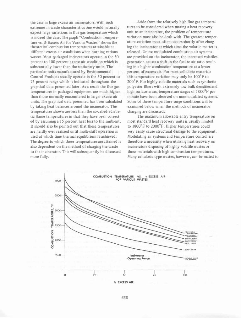
the case in large excess air incinerators. With such extremes in waste characteristics one would naturally expect large variations in flue gas temperature which is indeed the case. The graph "Combustion Temperature vs. % Excess Air for Various Wastes" shows the theoretical combustion temperatures attainable at different excess air conditions when burning various wastes. Most p'ackaged incinerators operate in the 50 percent to 100 percent excess air condition which is substantially lower than the stationary units. The particular units manufactured by Environmental Control Products usually operate in the 50 percent to 75 percent range which is indicated throughout the graphical data presented later. As a result the flue gas temperatures in packaged equipment are much higher than those normally encountered in larger excess air units. The graphical data presented has been calculated by taking heat balances around the incinerator. The temperatures ,shown are less than the so-called adiabatic flame temperatures in that they have been corrected by assuming a 15 percent heat loss to the ambient. It should also be pOinted out that these temperatures are hardly ever realized until multi-shift operation is used at which time thermal equilibrium is achieved. The degree to which these temperatures are attained is also dependent on the method of charging the waste to the incinerator. This will subsequently be discussed more fully.
Aside from the relatively high flue gas temperatures to be considered when mating a heat recovery unit to an incinerator, the problem of temperature variation must also be dealt with. The greatest temperature variation most often occurs shortly after charging the incinerator at which time the volatile matter is released. Unless modulated combustion air systems are provided on the incinerator, the increased volatiles generation causes a shift in the fuel to air ratio resulting in a higher combustion temperature at a lower percent of excess air. For most cellulosic materials this temperature variation may only be 100°F to 200°F. For highly volatile materials such as synthetic polyester fibers with extremely low bulk densities and high surface areas, temperature surges of 1 OOO°F per minute have been observed on nonmodulated systems. Some of these temperature surge conditions will be examined below when the methods of incinerator charging are discussed.
The maximum allowable entry temperature on most standard heat recovery units is usually limited to 1800°F to 2000°F. Higher temperatures could very easily cause structural damage to the equipment. Modulating air systems and temperature control are therefore a necessity when utilizing heat recovery on incinerators disposing of highly volatile wastes or those materials with high combustion temperatures. Many cellulosic type wastes, however, can be mated to
COMBUSTION TEMPERATURE vs. % EXCESS AIR
... .
z o ;::: V'I i2000 �
1500
o 25
FOR VARIOUS WASTES
50
Incinerator Operating Range
% EXCESS AIR
358
75
I'OlTU"'I""1 11.", MOIIf"'"
..ot,.unUMI (lOll MOInIMII
... v ..... WOOD tIS" MOtIf" •• \
"PI 0 WA"I ",. I .... n.
NA'U'''' 1"".1 tlSIl .otnuel\
100

heat recovery equipment with a minimum of automatic controls.
CONSTANCY OF FLOW
Just as important as temperature control is the factor of constant flue gas flow through the heat recovery equipment. Although properly designed heat transfer equipment can tolerate increased gas flow rates within certain limits with resulting increased heat transfer coefficients, severe gas flow variation should be avoided especially when it occurs on a cyclical basis. Control of this parameter therefore would also dictate modulated combustion air systems on the incinerator to minimize the gas flow during volatiles generation on charging and to maximize gas flow during the period in which the fixed carbon content of the waste is undergoing combustion. This condition results in maximum incineration rates with maximum heat recovery rates.
Some idea of the flue gas flow variation may be obtained from Table 1 below. The flow variations shown are all based on incinerators without modulated air systems.
TABLE I: FLUE GAS FLOW VARIATION
Number of Tests Maximum Flow Waste Material Observed Variation, %
Highly volatile polyester fibers 12 65.3
Hospital waste 7 20.7
Pathological 8 15.8
Rubber tires 3 23.9
Hardwoods 3 22.7
Type I waste 3 12.7
PARTICULATE GRAIN LOADING
One of the major attractions offered by packaged incinerators lies in their ability to reduce combustible material to sterile ash and produce combustion gases with extremely low particulate loading. As a general rule then, providing clean flue gases for use in heat recovery equipment presents the least problem. There are exceptions to this however even on controlled air units and these will be discussed below. Some authorities place a limit on particulate loading of flue gases to be used in heat recovery applications at 0.5 [2] grains per cubic foot in fire tube boilers. Higher loadings can be handled by watertube units. Based on the writer's observations, a maximum design loading
of 0.15 grains per cubic foot is normally used to prevent fouling of tube surfaces. Heat recovery equipment subjected, to higher loadings is usually provided with automatic soot blowers.
Table II lists experienced combustion gas grain loadings from a number of waste materials. Care should .be taken not to confuse the grain loadings shown with the commonly encountered emission code values used by most states which are values adjusted to a 12 percent CO2 basis. The loadings shown in the table are based on stack conditions. The column based on stack conditions represents approximate inlet conditions seen by the heat recovery equipment. The second column based on a temperature of 450°F represents the approximate conditions at the exit of any heat recovery equipment coupled to the incinerator. All of the values reporte.d were determined through use of the standard particulate sampling train [3] recommended by the Environmental Protection Agency and, as such, the particulate reported includes both the dry and wet particulate catch.
As can be seen from the table, the cleanliness of the combustion gases make them ideally suited for heat recovery applications within firetube or watertube recovery units. The only exception is the flame retardant polyester materials. Flame retardant materials usually have varying amounts of antimony oxides and chlorides which are easily carried over with the combustion gases. Combustion of these materials with subsequent heat recovery could best be handled with watertube surfaces. Other commonly encountered and easily entrained inorganics leading to high particulate loading of the flue gases include phosphorous oxides, titanium dioxide (commonly used as a white pigment), clays of all sorts and aluminum oxides. The chemistry of the waste material must certainly be well known before undertaking any attempts at heat recovery. This is true not only from the point of carryover onto the heat transfer surfaces with subsequent fouling but also because of the potential corrosion of heating surfaces due to the presence of inorganics.
CORROSION PROPERTIES
Although extensive studies have been made concerning the chemistry of corrosion of boiler surfaces by flue gases, many unanswered questions remain. The various corrosion reactions taking place are so complex that only a word will be said here. It has been stated that more than two hundred [4] reaction steps can be involved in the chemistry of corrosion. Several excellent [4,5,6] papers have been presented and
359

TABLE I I. PARTICULATE GRAIN LOADINGS for VARIOUS WASTES
Pounds /Hour Grains /CF Grains /CF Waste Material Fuel Burning Rate @ Stack Cond. @450°F
Hospital waste G 509 0.0097 0.0227 Hospital waste G 500 0.Ql 1O 0.0263 Hospital waste G 520 0.0088 0.0218 Hospital waste G 502 0.0094 0.0234 Hospital waste 0 1533 0.0168 0.0309 Hospital waste 0 1578 0.0200 0.0470 Hospital waste 0 1626 0.0159 0.0278
PHS waste (Type 1) G 500 0.0092 0.0177 PHS waste (Type 1) G 500 0.0099 0.0183
Pathological (Type 4) G 250 0.0085 0.Ql 73 Pathological (Type 4) G 250 0.0072 0.0148 Pathological (Type 4) G 400 0.0130 0.0279 Pathological (Type 4) G 400 0.0117 0.0253
Rubber Tires G 1200 0.0113 0.0298 Rubber Tires G 1200 0.0177 0.0483
Wood waste (hardwoods) G 1167 0.0082 0.0188 Wood waste (hardwoods) G 1145 0.0101 0.0216 Wood waste (chipboard) G 825 0.0072 0.0163
Oil impregnated filter G 405 0.0051 0.0122 media
Oil impregnated filter G 416 0.0037 0.0088 media
Rubber (30% clay) G 810 0.0587 0.1250
Polyester waste G 1487 0.0088 0.0201 Polyester waste 0 1290 0.Ql 72 0.0528 Polyester waste 0 1174 0.0130 0.0338 Polyester waste 0 1192 0.Ql16 0.0292
Flame retardant poly- 0 1399 0.9219 2.260 esters
Flame retardant poly- 0 1126 0.8497 2.210 esters
Organic liquids 0 363 0.0094 0.0243 (20% inorganics)
Organic liquids 0 363 0.0087 0.0227 (20% inorganics)
o - Oil fired unit
G - Gas fired unit
further details on the reaction mechanisms may be 2. Low temperature or dew-point corrosion obtained there. Suffice it to say that the primary 3_ Hydrogen chloride corrosion sources of boiler tube corrosion consist of one or 4. Corrosion due to localized reducing atmos-more of the following: pheres within the boiler.
1. High temperature liquid phase corrosion It is generally agreed that corrosion from the probably due to molten alkali-metal sulfates fust source can be eliminated by keeping metal tem-
360

peratures below 900°F. Low temperature corrosion can be eliminated by maintaining exiting gases from the heat recovery equipment above their dew-points. It has generally been our practice to use 450°F as the minimum exiting design temperature. This is sufficiently high to avoid dew-point problems with hydrogen chloride and sulfur oxides in the concentrations normally encountered in industrial wastes. Specialized chemical wastes high in these component concentrations should be evaluated on an individual basis. Hydrogen chloride is a commonly found source of corrosion and especially so in packaged type incinerators in that they are called upon to dispose of 100% concentrations of many chlorinated wastes such as polyvinyl chloride plastics, neoprene rubber and various chlorinated waste solvents. Some authorities [5] feel that attack by hydrogen chloride and free chloride gas can be minimized by maintaining flue gases above the dew-point and operating pressures such that the metal temperature does not exceed 550°F. It is important that incinerators burning chlorinated wastes have electrical circuitries that provide for pre- and post purging of the incinerator and heat recovery system to avoid condensation of hydrogen chloride during the transient periods.
Corrosion due to localized reducing atmospheres is probably minimal in packaged equipment due to the compact geometry and intimate mixing of excess air and combustion gases within the incinerator. Several boiler manufacturers have so-called turbulizers within firetube boilers to prevent stratification of the gases and to avoid laminar flow, a condition which would aggravate this type of corrosion.
It should be pOinted out that corrosion of heat recovery surfaces exposed to hydrogen chloride and sulfur oxides simultaneously undergo much more rapid corrosion rates than when exposed to only one of the components. This is apparently due to the formation of the two highly reactive inorganic acids, namely, hydrochloric and sulfuric acid. Incinerators and heat recovery equipment exposed to these components simultaneously require special attention.
VOLATILITY OF WASTE
The relative volatility of the waste material is important to us here only insofar as the resulting surges of combustion temperatures and flow rates as seen by the heat recovery equipment. As stated previously, modulated. air systems and temperature controls are a necessity for stabilization of the flue gases when incinerating highly volatile wastes. Different
approaches are being taken by the respective incinerator manufacturers and much of the detail on how this control is carried out is presently proprietary in nature.
METHODS OF INCINERATOR CHARGING
The method of incinerator charging has a direct effect on the characteristics of the combustion gases going from an incinerator to the heat recovery equipment. The ideal condition for any heat recovery application would be the continuous introduction of waste material to the incinerator, almost constant volatiles generation and constant fuel to air ratio with resulting steady flue gas temperature. Unfortunately, most packaged type incinerator installations employ mechanical ram type feeders of various sizes which give a semi-batch charging or slugging of the incinerator. Even here though, heat recovery can easily be undertaken if proper considerations are given to the waste characteristics and provision of modulated air systems for the more volatile materials.
Discussion at the point will center primarily on feeding equipment manufactured by Environmental Control Products but should be typical for other manufacturers. The basic types of feeding equipment consist of the following:
1. Pneumatic feeders 2. Automatic dual ram feeders 3. Small single ram feeders 4. Large single ram feeders Drawings of these units are given on the follow
ing pages. The pneumatically fed incinerator is by far the ideal condition for heat recovery. All of the parameters mentioned above are met. The temperature profile (see Temperature Profile No. 1) shows a steady flue gas temperature except when material outage occurs. Pneumatic systems of course assume that the particular waste is one which lends itself to shredding. From the shredder, the material passes to a live bottom hopper from which it is metered either by screw conveyor or drag chains to-the pneumatic blower. A further advantage of this system lies in the fact that incineration rates and, therefore, heat recovery rates are not so dependent on an operator. The only requirement is that there be material in the storage hopper. Pneumatic systems are completely automatic and represent the optimum method of heat recovery from packaged incinerators.
Dual ram feeders are basically automatic in operation and insert waste into the incinerator while withdrawing the waste from a storage hopper. The dual ram feeder will continue to feed the incinerator so long as material is in the storage hopper. As in pneu-
361

1--
-J;- - ---1 -----T , - :1 - - -- ---- --- - -- - - -- - --f.-- ---
I , : 1 -v
: : . �: • " ... 1'1
�- . -. -,
1 !
362
\ \

\
i 1 l , 1 \
363

364

TEMPERATURE PROFILES
If--'' 7�' r.-3fOO+-- ROCHISH . N.Y .. U.S."- CI-fAA1- 82:',:; \I) �
� t- --r- - r - f--. r- , - r -+- r--- t- --+- - I--- -- -- f- ___ l-u'-_ --I--- r--r--r--t--+-...t=: _f-_l=._L_-r==
�- -:- -'" "'''" �- + �-=:n . L--�fV\.L 1- , r r L i-. f --t-- + -� f-- J===r--r-I. 1-- j--- - I- + :1 : -:- �- 7 �r. L f ---.� r-:�_ - -f 1..-£ f'. .'-! - - -,
i - t -t---r:-T-- �- *- - - -- i r � -�-,--l-r----:.-!- - t_ - f- -f -f ---f-- �- - f-- r-
t- - ' �r ;... --t- - 1--- I t __ . . • .J "oJ + - , - _.- t
-__ �-' r- . i r - -t- �
f - � . _ - - ; ii- �;,.--I -I -� - • ---- +- . :-'-.... ''''--i-- --t-- -t- - t--f -4 �-
--
f--, -i J t- - L f-- -. _ r --- 1_ -of -f-- I-- ---f- ,-_+--t--
NO. 1 PN EUMATICALLY FED UNIT, 450#/HR.
POL YSTYRENE
NO.2 BATCH TYPE F E EDING WITH SMALL SINGLE
RAM F E ED ER, 200# PER CHARGE OF NEOPRENE
RUBBER,400#/HR.
365
t----
r--r-'

.1-
, �. r--�--r--c- �r- - -"--+-- f----l 1-- -\ -L - -t--
• .,. iI'i"-+---' r- I--'� -f --+ ... i. . -!."" �-� _.. � -r� NO_ 3 BATCH TYPE FEED ING WITH LARGE SINGLE
RAM F E EDER, 600 TO 800# PER CHARGE OF
HIGHLY VOLATILE POLYESTER WASTE,
1200#/HR_
-r-- -� c- 1-- . . t- -T' + - � +- t-- � -- L-HH-- --- :- . __ L-_ f-- _.j---t---';'-_. -- + -+ - � -.
-- ---'.:--r--t--� __ c . \-i-.,, - "''''-f-r---' r-- -+---� --.-�-... ,.,.,,_� __ L . __ + ____ --- ,-- ' ---�-.., '",.... -
-:--_.: \:-�
-'
'!.�-
--( r'" :--�"':�-r -f-w'T""'"' .� . . - . '41'''''':-_'"" ,,,,,-� bi-:- f - r-\' - -+- t--: .- . - :)- ' - , __ "L _�_�
NO_ 4 SAME AS PROFILE NO_ 3 BUT WITH I NJ ECTION
. OF WASTE LIQUIDS @ 2 GPM.
366

matic systems, all materials cannot be handled by a dual ram. The dual ram works especially well in hospital applications where most of the waste has been bagged. Anti-bridging devices are normally required inside the storage hopper.
Single ram feeders are broken down into small (up to 60ft3 capacity) and large (60ft3 to 200ft3 capacity) sizes. A typical temperature profile (see Temperature Profile No. 2) for a small size feeder indicates that even with slug type feeding, the combustion gas temperature is not too variant once the unit has attained thermal equilibrium. The only disadvantage is that the single ram feeders, small and large, require that an operator be present to place fresh charges of waste material into the feeder.
It should be pointed out that all of the temperature profiles shown were taken from installations without modulated air systems. One could expect therefore that this refinement would further even out the profiles.
Perhaps the most dramatic illustration of the need for modulated air is shown on Temperature Profile No. 3 while charging large quantities of a highly volatile polyester waste. The extreme variations occured even though the primary combustion chamber was operated at less than stoichiometric air. Temperature Profile No. 4 is typical for the same polyester waste but with decreased volatility due to the cooling effect of the primary combustion chamber brought about by the simultaneous injection of waste liquids with fairly high water content.
The point here is not to make general statements concerning the best type of loading equipment to be used on heat recovery applications but to stress the importance of evaluating each system as to the effect of variation in flue gas going to the heat recovery equipment. The type of loading system is usually determined by the waste to be handled. The heat recovery system is then designed to meet these requirements.
TYPES OF HEAT RECOVERY EQUIPMENT
Heat recovery potential from packaged incinerators may manifest itself in the form of gas to air, gas to water, gas to thermal fluids or, perhaps the greatest efficiency of all, direct dilution of flue gases with air for drying or processing purposes. All of these possibilities, however, represent special cases and must be treated as such. By far the greatest potential and most direct approach lie in the generation of steam in waste heat boilers. The remainder of this oaper will be concerned with this phase of heat recovery, efficien-
cies and cost data for typical systems. Recuperation of energy in waste heat boilers
may be done with fire tube or watertube boilers. Firetube boilers are quite satisfactory for most cases. They require basically clean gases which as shown earlier is no problem for packaged incinerators and most waste materials. Grain loadings should not exceed 0.15 grains per cubic foot without giving consideration to automatic tube cleaning. In no case should the particulate loading exceed 0.5 grains per cubic foot. Firetube boilers are inherently limited to generating steam up to a maximum of 250 psi. (200 psi. on larger units). Steam output is usually limited to 15,000 pounds steam per hour. As will be shown below, the above output limitation is not a problem on the range of packaged incinerators under discussion in that this degree of steam generation is not approached. Firetube boilers have a substantially lower first cost compared to watertube units. The maximum inlet gas temperature should be limited to the range of 1800° tp 2000°F.
Watertube boilers should certainly be considered when the incinerator flue gases are heavily laden with particulate matter. Higher pressure steam may be generated in a watertube unit along with higher steam capacities. These characteristics in themselves, however, would probably have minimal influence on selection of a watertube unit for use on a packaged incinerator after considering the steam capacities involved and the working steam pressures most normally required by the light industrial users. Although the first cost of watertube units is higher, some versatile design features exist with only watertube equipment. The tube sizing and spacing may be varied to minimize the effects of slagging and erosion. Greater variations in gas temperature can be tolerated without damage to the unit. Explosion hazards are considered to be less and the resulting damage, should an explosion occur, is usually less than in a firetube boiler. A further advantage is that the water side is more easily cleaned and is not quite as susceptible to poor feedwater conditions.
In both cases the incinerator-waste heat recovery system must be provided with emergency interlocks to bypass flue gas in case of low water condition or high pressure.
A further consideration is the dependability of the waste supply. If the stearn demand is critical, auxiliary burners may be adapted to the waste heat boiler to provide steam during periods when waste material is not available.
Auxiliary. burners can easily be provided and are presently available on packaged fuetube units.
367

The boiler consists of a radiant furnace section with auxiliary burner and single pass convection section. Above this pass is located a second single pass convection area for the waste flue gases from the incinerator. The burner can be modulated to even out the steam demand requirements. Although different auxiliary burner ratings are available, the most frequently used one is comparable to 125 boiler horsepower.
HEAT RECOVERY CAPABILITIES
As is the case with any heat recovery equipment operating above a dew-point and receiving gases with moisture content, 100% recovery of the heat from the incineration process is not possible.
The primary heat inputs and outputs on an incinerator are as follows:
Basis: I#Waste @ 70°F
Inputs QI = 1 X AHc Outputs QOl = Sensible heat to raise combustion gases
from reference temperature to combustion temperature
MgCpAt
Q02 = Heat required to evaporate contained moisture
= MmAHv Q03 = Heat required to evaporate moisture
formed on combustion
= McAHv Q04 = Heat losses from system (taken as 15% of
total)
= 0.15AHc where,
Mg = mass flow of combustion gases including moisture, #/#waste
Cp = average specific heat of combustion products
At = combustion temperature minus 70°F
Mm = mass fraction of contained moisture
Mc = mass moisture formed on combustion, #/#waste
AHv = latent heat of vaporization for water @70°F
ARc = heat of combustion of waste as fued, Btu /#
Heat Balance QI = QOl + Q02 + Q03 + Q04 The heat quantities represented by Q02 and
Q03 cannot be recovered in the boiler in that the exiting flue gases remain above the condensation point for water. Item Q04 cannot be easily recovered. Only a portion of item QOl can be recovered in that the exiting flue gases leave the heat recovery boiler at 450°F approximately instead of 70°F.
Similar heat balances can be made for any waste material if the combustion reactions are known. The results of a number of these balances are given on the following graphical data. This data is presented as "Recoverable Heat" in Btu /#waste as fired and as "Recovery Percentage". The top curve in each case is based on flue gases attaining the combustion temperatures mentioned earlier. The bottom curves in each case represent values obtained with flue gases 200°F lower than the calculated combustion temperature.
Based on this data, some typical steam generating capabilities for various wastes assuming feedwater at 60°F and saturated steam at 212°F and 50% excess air conditions are as follows:
# SteamL# Waste Waste High Value Low Value
Natural rubber (15% 6.2 5.3 mOisture)
Average wood (15% 4.1 3.7 mOisture)
Polyethylene (10% 11.8 10.8 mOisture)
Polystyrene (10% 10.1 9.3 mOisture)
Type 0 waste 5.0 4.5
Type 1 waste 3.7 3.3
Type 2 waste 2.1 1.8
TYPICAL INSTALLATION
So as to review some of the design parameters discussed here, description of a typical heat recovery installation will be given. Environmental Control Products has recently installed a heat recovery unit coupled with an incinerator to burn 400#/Hr. of neoprene rubber (Refer to Photographs 1,2, 3 and 4). The combustion of neoprene results in the formation of hydrogen chloride which can .occur in stack concentrations of approximately 3% by volume at a 50% excess air condition. The incinerator is fed by a small single ram feeder. Heat recovery is by means of a
368

PHOTOGRAPH 1 PHOTOGRAPH 3
PHOTOGRAPH 4
369

RECOVERY PERCENTAGE
FOR
60 }fa tuzoal R,ubbeJ" lS:C MDhtu:r.)
40+-------���� a 50 100
% EXCESS AIR
70�--------------�
% 60
50+-------�--�--, a 100
% EXC ESS AIR
70,-------�--�--�
% 60
50+-------+---�� o 50 100 % EXCESS AIR
VARIOUS WASTES
370
70,-------------__
60
SO�------+_--�� o so 100
% EXCESS AIR
70�------------�
60
50+------4--�--� o 50 ,100
% EXCESS AIR
60
so
40 +----t-----''-----1 o so 100
% EXC ESS AIR

BTU
RECOVERABLE HEAT
BTU!#WASTE AS FIRED
FOR VARIOUS WASTES
80010---------------__
5000+-------�------� 301��------+---�--� o 50
% EXCESS AIR
100
i4001n---------., Po1pthy1 ...
{lO� Mltl.�
1300
1200
1100�--------�------� o 50 100
% EXCESS AIR
371
o 50 100 % EXCESS AIR
1100
10000
90001�------�--�--� o 50 100
% EXCESS AIR

RECOVERABLE HEAT
BTU/#WASTE AS FIRED
FOR VARIOUS WASTES
7000�--------------- 6000 -......-----_--. '!'Jpe 1 v ....
6000 sooo
sooo
4000 -t------t----'---t )000 �-__ _I__-L-_ _f o So 100 o so 100
% EXCESS AIR % EXCESS AIR
4000 TJpe 2 V.ate
3000
B'l'U
2000
1000�------�--��� o 100
% EXCESS AIR
372

single pass firetube boiler, 250 psi ASME design. So as to maintain steam during periods of low waste availability, the boiler is equipped with a 125 bhp auxiliary burner with radiant furnace and single pass convection tubes. The waste heat side of the boiler generates approximately 84 boiler horsepower giving a total steam capacity of 205 bhp. In that the boiler is separated from the incinerator by approximately twenty feet, light weight breeching conducts the gases from the incinerator to the boiler. Diverter valves are provided which automatically bypass the boiler in emergency conditions. Since the volatility of the waste is fairly stable, a minimum of modulating air control is required. The only special air control consists of two stage underfire air. Gases going to the boiler are fairly steady at 1800°F. Prepurging and postpurging of the complete system is carried out to avoid dew-points of the hydrogen chloride. After passing through the heat recovery unit, the gases then enter a 6"wc pressure drop scrubber to remove the hydrogen chloride before going to atmosphere. The scrubber sump is equipped with automatic pH control and caustic injection for neutralization of the acidic water before passing to an industrial waste line. Sample boiler tubes have been suspended on the cold end of the boiler for corrosion studies. The exhaust stack from the boiler is divided into two sections. The one section carries the combustion gases from the auxiliary burner side to atmosphere. The waste heat gases pass through the second section directly to the scrubber. This mini-
mizes the scrubber size and facilitates operation of the auxiliary burner during downtime of the incinerator and scrubber.
Operational feedback on this installation is expected to answer many of the present questions concerning not only heat recovery on packaged incinerators but provide useful information on the handling of chlorinated materials in heat recovery systems.
COST DATA
The graphical data presented below represent typical costs for incinerator-heat recovery modules. In that the economics become more attractive as continuity of operation is approached, all cost data and fuel worth of heat recovered are based on two shift per day operation. To do this means that automatic ash removal must be provided. All costs, therefore, include the following:
1. Oil fired incinerator with single ram feeder 2. Fire tube boiler, 125 psi ASME design 3. Feedwater tank and pump 4. All electrical interlocks and controls 5. Stacks and breechings for up to fifteen feet
separation between incinerator and boiler 6. Automatic ash removal module 7. 3000°F refractory 8. Startup and engineering
Installation and shipping costs are not included.
200,-______________________ ,
$, THOUSANDS
180
160
140
120
eqUipment Cost
Annual Value 0 l Heat
80,000
60,000
40,000
100 -1-----..-------.------+-20,000 1000 1500 2000 2500 INCINERATION
· RATE
#/HR. TYPE 1 WASTE
373
$/YEAR

Type 1 waste is assumed with a heat recovery percentage of 55 (low value) being used to calculate net fuel worth.
Net worth of fuel is determined by deducting the auxiliary fuel required for the incineration process and figuring the equivalent fuel oil represented by the recovered heat at an 80% boiler efficiency. Oil cost is figured at a current cost of $0.27 per gallon. Based on this data, annual returns on investment of 23.6, 30.3, 34.8 and 36.7 percent are obtained on the 1000, 1500, 2000 and 2500 pound per hour units respectively (based on Type 1 waste). This is equivalent to payoff times of 4.2, 3.3,2.9 and 2.7 years respectively. Higher figures of returns are realized when incinerating lower moisture content and higher Btu wastes as indicated above under the section, "Recovery Percentage."
CONCLUSIONS
The returns on investment above include the incinerator and ash removal costs. As is often the case, the cost of the incineration equipment has already been justified on the basis of hauling, compacting or
landfilling charges. The case for heat recovery then becomes even more attractive in that the returns on investment annually of the heat recovery equipment only are more than two times the above figures and with pay�ff times less than one half those given above. It is our opinion that more and more packaged incinerator installations will be coupled with heat recovery. This will undoubtedly occur out of necessity if current fuel shortages continue.
REFERENCES
[1) Richard C. Corey, "Principles and Practices of Incineration", Wiley-Interscience, 1969.
(2) Carl D. Shields, "Boilers, Types, Characteristics, and Functions", McGraw-Hill, 1961.
(3) Federal Register, Vol. 36, No. 247, Title 40, Part 60, Figure 5-1, Thursday, Dec. 23, 1971.
(4) R. Rasch and M. Hirsch, "Brennstoff-Warme-Kraft", Vol. 10, No. 10, p. 489,1967.
(5) J. W. Regan, Generating Steam From Prepared Refuse, Proceedings of 1970 National Incinerator Conference, ASME, New York, N.Y., 1970.
(6) Paul D. Miller and Horatio H. Krause, Corrosion of Carbon and Stainless Steels in Flue Gases from Municipal Incinerators, Proceedings of 1972 National Incinerator Conference, ASME, New York, N.Y., 1972.
374