heat recovery1 heat recovery system mebs6008. heat recovery2 heat recovery system process-to-comfort...
TRANSCRIPT
Heat Recovery 1
Heat Recovery System
MEBS6008

Heat Recovery 2
Heat Recovery System
Process-to-Comfort Comfort-to-Comfort
Heat Recovery 3
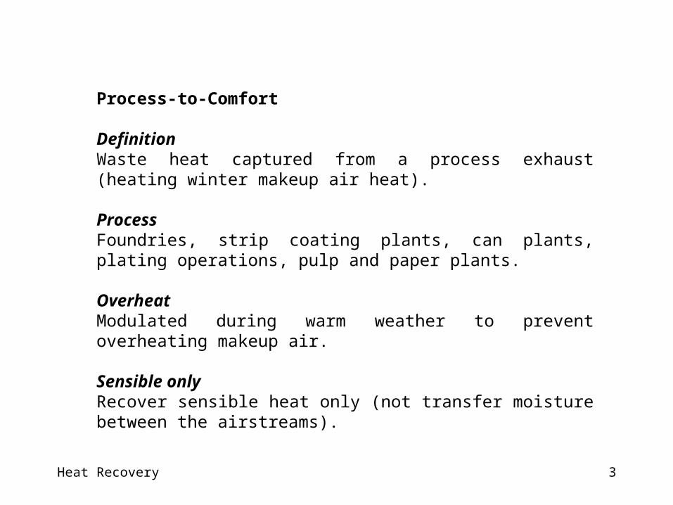
Process-to-Comfort
DefinitionWaste heat captured from a process exhaust (heating winter makeup air heat).
ProcessFoundries, strip coating plants, can plants, plating operations, pulp and paper plants.
OverheatModulated during warm weather to prevent overheating makeup air.
Sensible onlyRecover sensible heat only (not transfer moisture between the airstreams).

Heat Recovery 4
Comfort-to-Comfort
DefinitionHeat recovery device lowers the enthalpy of the building supply air during warm weather and raises it during cold weather
Approach Transferring energy between the ventilation air supply and exhaust airstreams.
Product Commercial and industrial energy recovery equipmentResidential and small-scaled commercial: Heat recovery ventilators [Small-scale packaged ventilators with built-in heat recovery components]
Sensible + LatentSensible heat devices (i.e., transferring sensible energy only) or total heat devices (i.e., transferring both sensible energy and moisture)
Heat Recovery 5
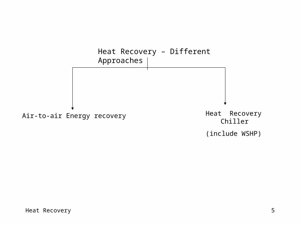
Heat Recovery – Different Approaches
Heat Recovery Chiller
(include WSHP)Air-to-air Energy recovery
Heat Recovery 6
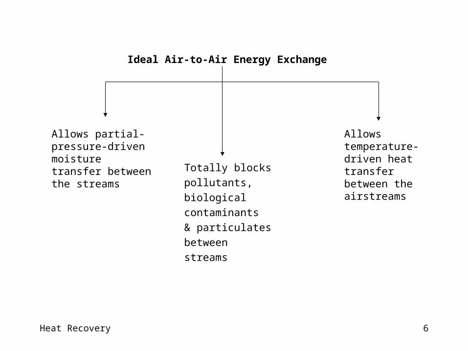
Ideal Air-to-Air Energy Exchange
Allows temperature-driven heat transfer between the airstreams
Allows partial-pressure-driven moisture transfer between the streams
Totally blocks pollutants, biological contaminants & particulates between streams
Heat Recovery 7
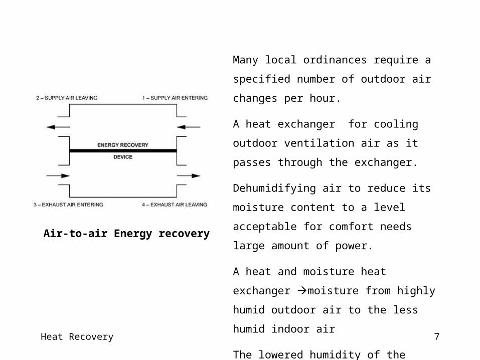
Many local ordinances require a specified number of
outdoor air changes per hour.
A heat exchanger for cooling outdoor ventilation air
as it passes through the exchanger.
Dehumidifying air to reduce its moisture content to a
level acceptable for comfort needs large amount of
power.
A heat and moisture heat exchanger moisture
from highly humid outdoor air to the less humid
indoor air
The lowered humidity of the entering ventilation air
substantial savings of energy.
Air-to-air Energy recovery
Heat Recovery 8
Compliance with Codes
ANSI/ASHRAE/IESNA Standard 90.1–2001
It sets minimum design requirements that encourage energy efficiency throughout the
building.
This standard requires the use of exhaust-air energy recovery when an individual fan system
meets both of the following conditions:
- Design supply airflow equals or exceeds 2.4 m³/s
- Minimum outdoor airflow equals or exceeds 70 percent of the design supply airflow
Heat Recovery 9
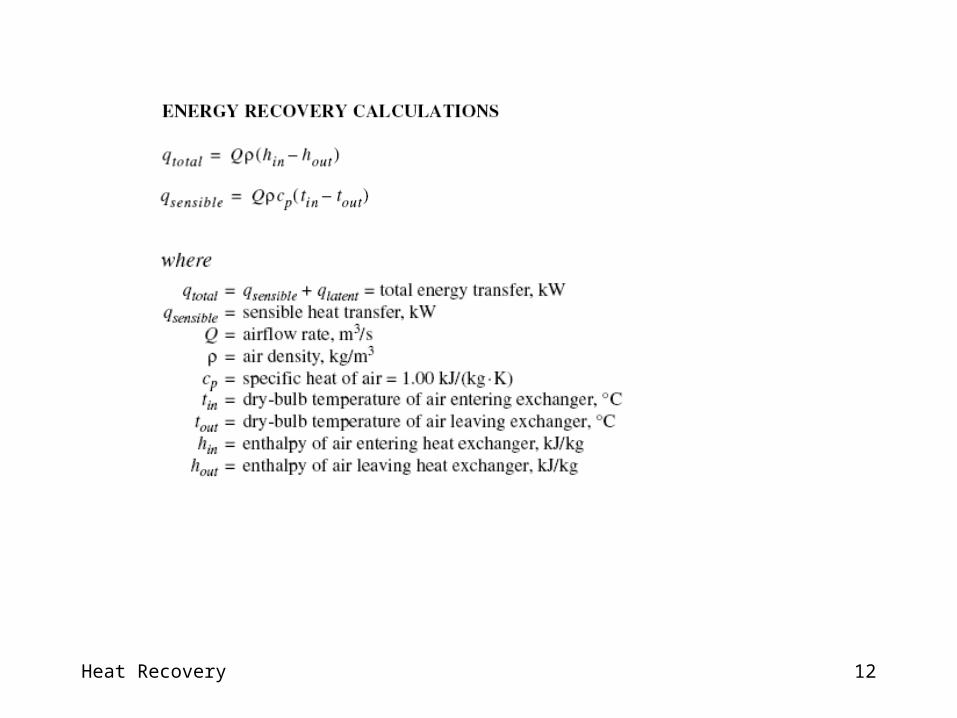
Rate of Energy Transfer
The rate of energy transfer depends on:
Exchanger geometry (parallel flow/counterflow/cross-flow, number of passes, fins),
Thermal conductivity of the walls separating the streams,
Permeability of walls to gases passage.
Cross-stream dry-bulb temperature differences heat transfer.
Cross-stream mass transfer Air, gases, and water vapor (may also in leakage)
Latent heat transfer as sensible heat water vapor condenses into liquid
Energy Transfer

Heat Recovery 10
(1) Establishes a uniform method of testing for obtaining performance data.
(2) Specifies the data required, calculations to be used. and reporting procedures for testing the performance
(3) Specifies the types of test equipment for performing such tests.
Performance Rating
ASHRAE Standard 84
Method of Testing Air-to-Air Heat Exchangers
ARI Standard 1060
Rating Air-to-Air Energy Recovery Ventilation Equipment
An industry-established standard for rating the performance of air-to-air heat/energy exchangers for use in energy recovery ventilation equipment.
Establishes definitions, requirements for marking and nameplate data, and conformance conditions intended for the industry.
Heat Recovery 11
Heat Recovery 12
Heat Recovery 13
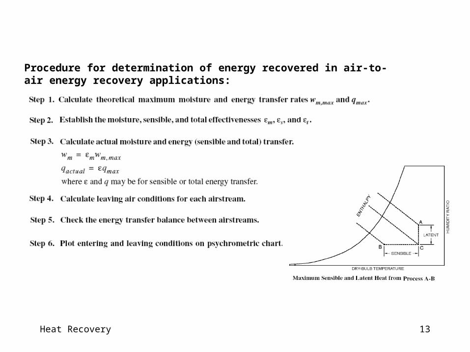
Procedure for determination of energy recovered in air-to-air energy recovery applications:
Heat Recovery 14
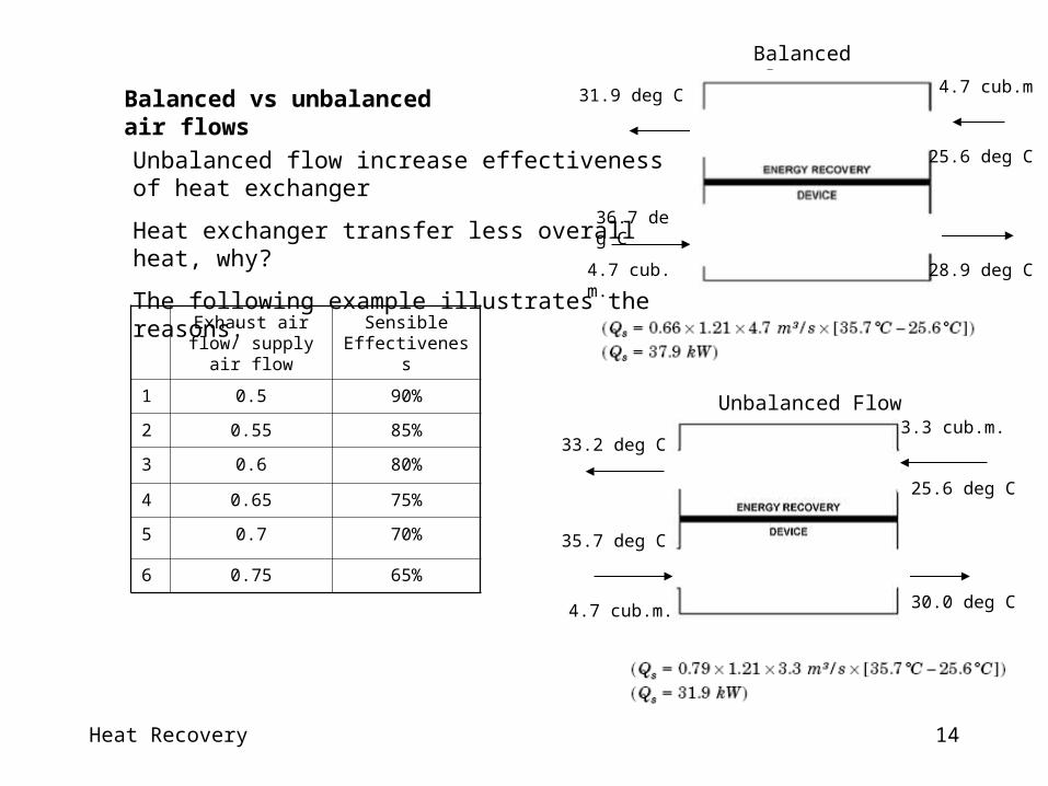
Balanced vs unbalanced air flows
Exhaust air flow/ supply air flow
Sensible Effectiveness
1 0.5 90%
2 0.55 85%
3 0.6 80%
4 0.65 75%
5 0.7 70%
6 0.75 65%
Unbalanced flow increase effectiveness of heat exchanger
Heat exchanger transfer less overall heat, why?
The following example illustrates the reasons:
Balanced Flow
Unbalanced Flow
4.7 cub.m.
4.7 cub.m
36.7 deg C
31.9 deg C
28.9 deg C
25.6 deg C
4.7 cub.m.
35.7 deg C
30.0 deg C
33.2 deg C3.3 cub.m.
25.6 deg C
Heat Recovery 15
Heat Recovery 16
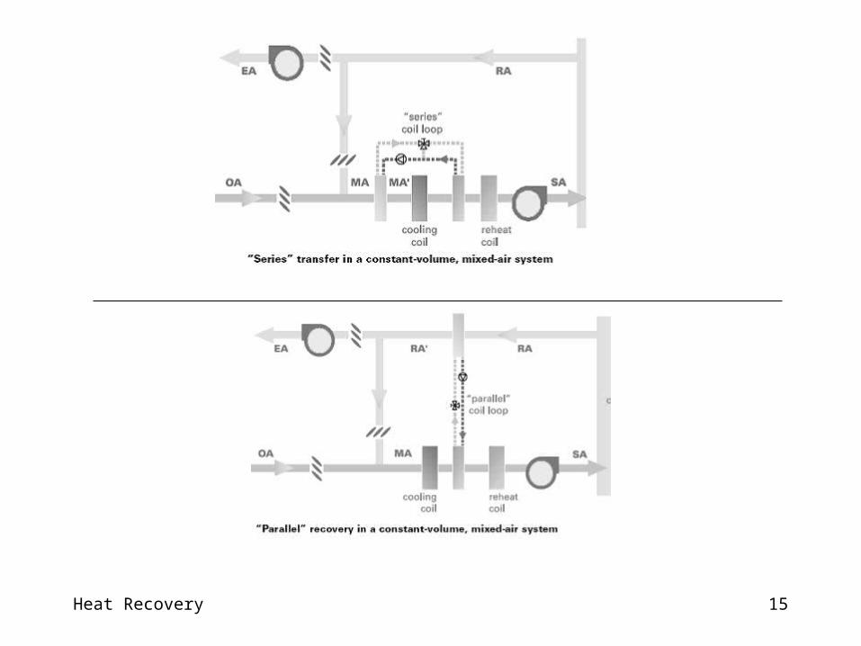
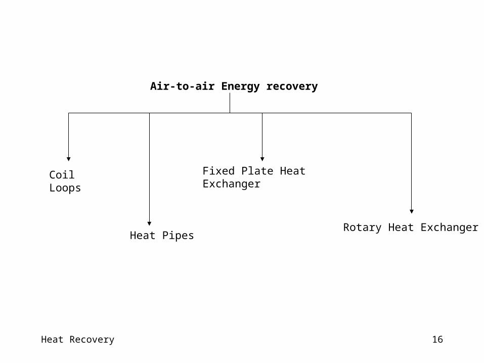
Air-to-air Energy recovery
Coil Loops
Heat Pipes
Fixed Plate Heat Exchanger
Rotary Heat Exchanger
Heat Recovery 17

Heat Recovery 18
Coil Loop• Two or more finned-tube coils that are piped together in a closed
loop
• A small pump circulates the working fluid through the two coils
• Working fluid - a solution of inhibited glycol and water through the two coils
• An expansion tank in the system
• Modulating capacity (three-way mixing valve or a variable-speed drive on the pump)
• The most flexible - transfer energy between air streams that are physically separated by some distance
• Recover energy from multiple exhaust-air streams (using multiple exhaust-side coils)
• Multiple coils - requires additional coils, more piping and glycol, and a larger pump.
Heat Recovery 19
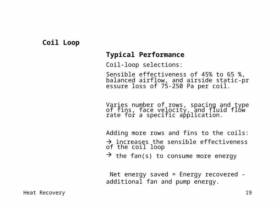
Coil Loop
Typical Performance
Coil-loop selections:
Sensible effectiveness of 45% to 65 %, balanced airflow, and airside static-pressure loss of 75-250 Pa per coil.
Varies number of rows, spacing and type of fins, face velocity, and fluid flow rate for a specific application. Adding more rows and fins to the coils: increases the sensible effectiveness of the coil loop the fan(s) to consume more energy
Net energy saved = Energy recovered - additional fan and pump energy.
Heat Recovery 20
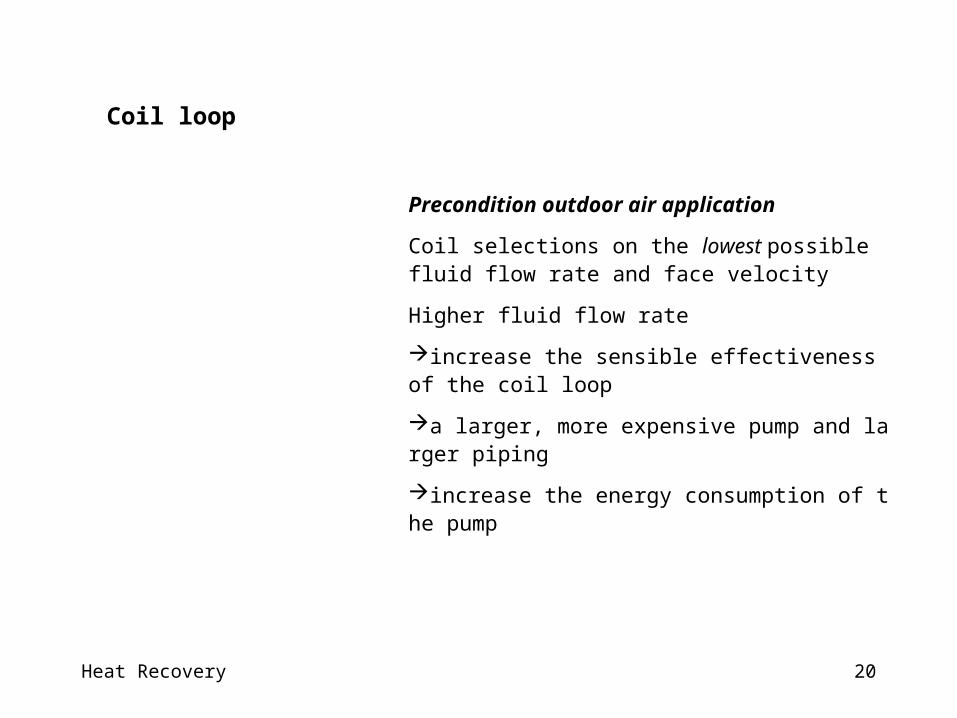
Precondition outdoor air application
Coil selections on the lowest possible fluid flow rate and face velocity
Higher fluid flow rate
increase the sensible effectiveness of the coil loop
a larger, more expensive pump and larger piping
increase the energy consumption of the pump
Coil loop

Heat Recovery 21
Coil Loops
Other Hints in design
For a coil loop that reheats supply air using series arrangement try to use two-row coils.
Minimizing the number of coil rows reduce fan power.
Maximize net energy savings OR downsizing potential for cooling and heating plants ??
Coils with fewer rows (four or six) and wider fin spacing (120 fins/ft)
reduces the pressure drop
maximize net energy savings (best payback)
Coils with more rows (eight) and with closely spaced fins (144 fins/ft)
maximize effectiveness max. the amount of heat recovered

Heat Recovery 22
Capacity Control
Three-way mixing valve or a variable-speed drive on the pump prevent the coil loop from overheating the supply air.
A temperature sensor in the supply air stream, downstream of the supply-side coil, monitors the leaving-air temperature.
The mixing valve then appropriately modulates the fluid flow rate through the supply-side coil.
Reduce flows through the supply-side coil
the loop adds less heat to the supply air stream/
modulating the fluid flow rate through the entire coil loop (variable flow)
Both the mixing valve and the variable-speed drive can provide equally effective
Location of the three-way mixing valve is critical in frost prevention mode.
Pump power reduce savings potential.
Coil Loop

Heat Recovery 23
Size the coil loop for minimum ventilation airflow, (not full economizer airflow).
Use bypass dampers in both air streams to reduce fan energy consumption when the coil loop is inactive.
Use bypass dampers not mixing valve or variable-speed drive for the pump for control capacity.
Outdoor-air preconditioning in a mixed-air system with airside economizer :
Coil Loop
Heat Recovery 24
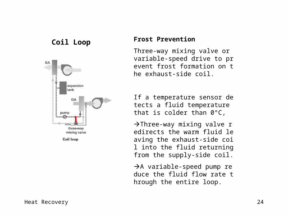
Frost Prevention
Three-way mixing valve or variable-speed drive to prevent frost formation on the exhaust-side coil.
If a temperature sensor detects a fluid temperature that is colder than 0°C,
Three-way mixing valve redirects the warm fluid leaving the exhaust-side coil into the fluid returning from the supply-side coil.
A variable-speed pump reduce the fluid flow rate through the entire loop.
Coil Loop
Heat Recovery 25
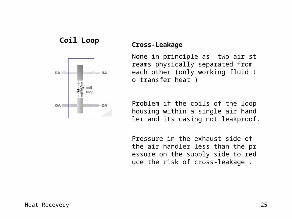
Cross-Leakage
None in principle as two air streams physically separated from each other (only working fluid to transfer heat )
Problem if the coils of the loop housing within a single air handler and its casing not leakproof.
Pressure in the exhaust side of the air handler less than the pressure on the supply side to reduce the risk of cross-leakage .
Coil Loop
Heat Recovery 26
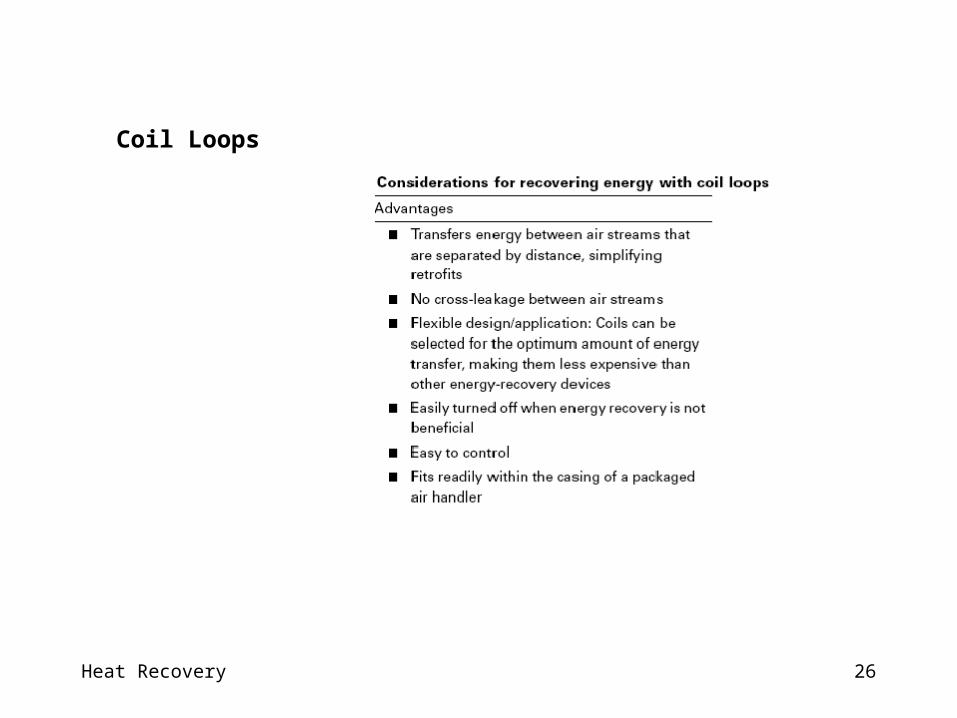
Coil Loops
Heat Recovery 27
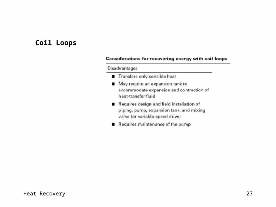
Coil Loops
Heat Recovery 28
Maintenance
Coil energy recovery loops require little maintenance. The only moving parts are the circulation pump and the three-way control valve.
However, to ensure optimum operation,
the air should be filtered,
the coil surface cleaned regularly,
the pump and valve maintained,
the transfer fluid refilled or replaced periodically.
Coil Loops

Heat Recovery 29
Thermal Transfer Fluids.
An inhibited ethylene glycol solution in water is commonly used when freeze protection is required.
An inhibited ethylene glycol break down to an acidic sludge at temperatures above 135°C.
A non aqueous synthetic heat transfer fluid for freeze protection and exhaust air temperatures exceed 135°C.
Coil Loops

Heat Recovery 30
FIXED-PLATE EXCHANGERS
Fixed surface plate exchangers have no moving parts.
Alternate layers of plates, separated and sealed (I.e. the heat exchanger core), form the exhaust and supply airstream passages.
Plate spacings range from 2.5 to 12.5 mm
Heat is transferred directly from the warm airstreams through the separating plates into the cool airstreams.
Heat Recovery 31
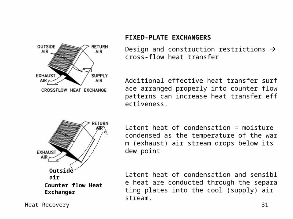
FIXED-PLATE EXCHANGERS
Design and construction restrictions cross-flow heat transfer
Additional effective heat transfer surface arranged properly into counter flow patterns can increase heat transfer effectiveness.
Latent heat of condensation = moisture condensed as the temperature of the warm (exhaust) air stream drops below its dew point
Latent heat of condensation and sensible heat are conducted through the separating plates into the cool (supply) air stream.
Moisture is not transferred.
Recovering min. 80% of available waste exhaust.Counter flow Heat Exchanger
Outside air
Heat Recovery 32
FIXED-PLATE EXCHANGERS
Design Considerations
Plate exchangers are available in many configurations, materials, sizes, and flow patterns.
Many are modular, and modules can be arranged to handle almost any airflow, effectiveness, and pressure drop requirement.
Plates are formed with integral separators (e.g., ribs, dimples, ovals) or with external separators (e.g., supports, braces, corrugations).
Air stream separations are sealed by folding, multiple folding, gluing, cementing, welding, or etc.
Heat Recovery 33
FIXED-PLATE EXCHANGERS
Design Considerations
Heat transfer resistance through the plates is small compared to the air stream boundary layer resistance on each side of the plates.
Heat transfer efficiency is not substantially affected by the heat transfer coefficient of the plates.
Aluminum is the most popular construction material for plates because of its non-flammability and durability.
Polymer plate exchangers have properties that may improve heat transfer by breaking down the boundary layer and are popular because of their corrosion resistance and cost-effectiveness.
Heat Recovery 34
FIXED-PLATE EXCHANGERS
Design Considerations
Plate exchangers normally conduct sensible heat only
Water-vapor-permeable materials, such as treated paper and new microporous polymeric membranes, for transferring moisture
Plate exchangers in modular design to allow capacity each of range 0.01 to 5 m3/s to form a one for 50 m3/s

Heat Recovery 35
Performance
Fixed-plate heat exchangers can economically achieve high sensible heat recovery and high total energy effectiveness
A primary heat transfer surface area separating the airstreams
No additional secondary resistance (i.e., pumping liquid, or transporting a heat transfer medium) for cases of other exchangers
Simplicity and lack of moving parts reliability, longevity, low auxiliary energy consumption, and safety performance.
FIXED-PLATE EXCHANGERS

Heat Recovery 36
Differential Pressure/Cross-Leakage
It is a static device built little or no leakage occurs between airstreams
As velocity increases, the pressure difference between the two airstreams increases exponentially
High differential pressures may deform the separating plates or even damage the exchanger (for differential pressures > 1 kPa - rare)
High air velocities & high static pressures require special exchangers.
FIXED-PLATE EXCHANGERS
Heat Recovery 37
Capacity Control
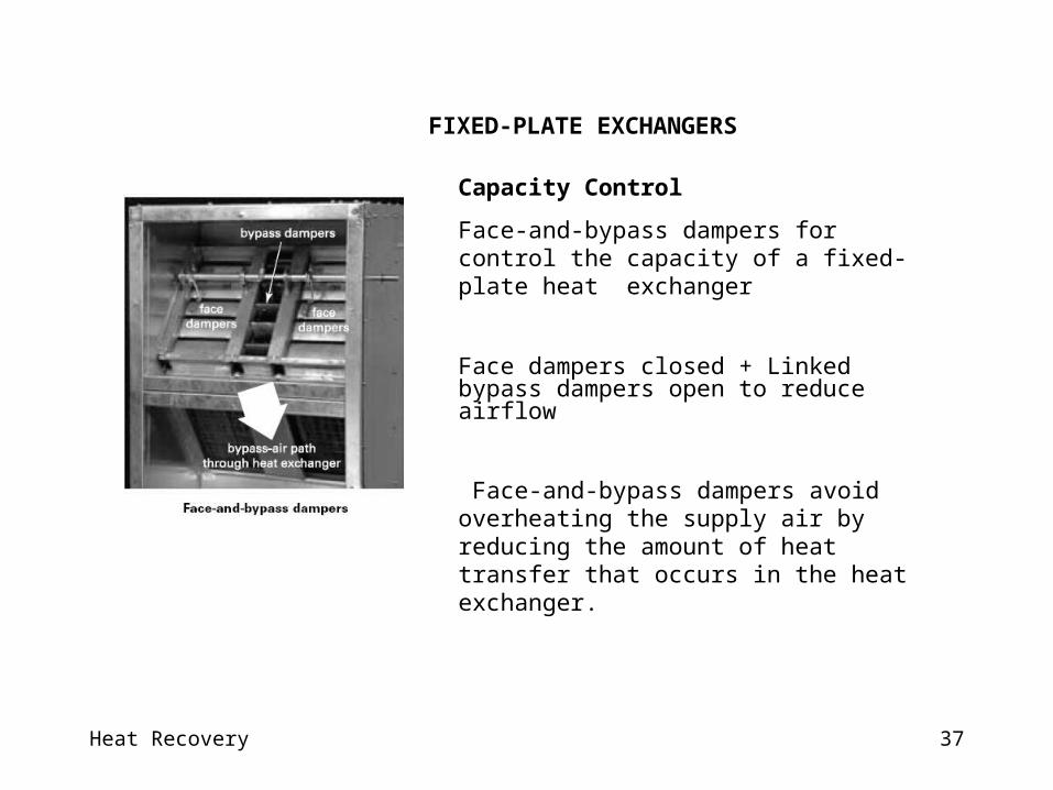
Face-and-bypass dampers for control the capacity of a fixed-plate heat exchanger
Face dampers closed + Linked bypass dampers open to reduce airflow
Face-and-bypass dampers avoid overheating the supply air by reducing the amount of heat transfer that occurs in the heat exchanger.
FIXED-PLATE EXCHANGERS
Heat Recovery 38
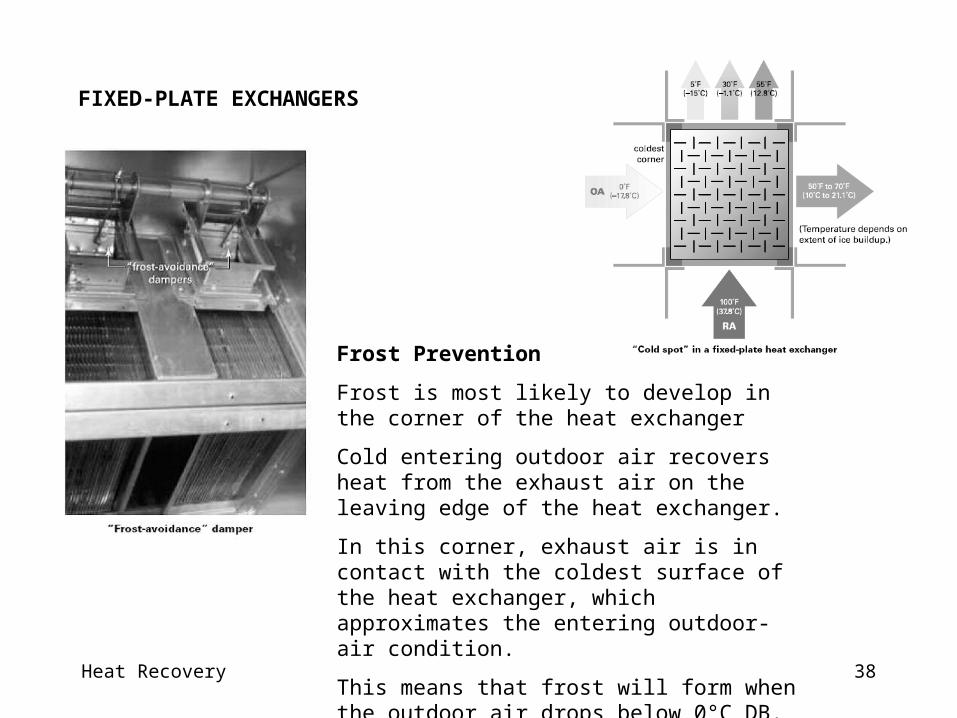
Frost Prevention
Frost is most likely to develop in the corner of the heat exchanger
Cold entering outdoor air recovers heat from the exhaust air on the leaving edge of the heat exchanger.
In this corner, exhaust air is in contact with the coldest surface of the heat exchanger, which approximates the entering outdoor-air condition.
This means that frost will form when the outdoor air drops below 0°C DB.
FIXED-PLATE EXCHANGERS

Heat Recovery 39
FIXED-PLATE EXCHANGERS

Heat Recovery 40
ROTARY AIR-TO-AIR ENERGY EXCHANGERS
A rotary air-to-air energy exchanger, or rotary enthalpy wheel, has a revolving cylinder filled with an air-permeable medium having a large internal surface area.
Adjacent supply and exhaust airstreams each flow through one-half the exchanger in a counterflow pattern.
Heat transfer media may be selected to recover sensible heat only or total heat (sensible heat plus latent heat).
Have a counter flow configuration and normally use small-diameter flow passages quite compact and with high transfer effectiveness.
A desiccant film coating on wheel surfaces absorbs moisture (wheel at more humid airstream). Moist desorbed from film less humid airstream.

Heat Recovery 41
Latent heat
1. The medium condenses moisture from the airstream with the higher humidity ratio (medium temperature <dew point or by desiccants )
2. Releases the moisture through evaporation (and heat pickup) into the air stream with the lower humidity ratio.
Sensible heat
The medium picks up and stores heat from the hot air stream and releases it to the cold on.
Heat Recovery 42
Construction
Air contaminants, dew point, exhaust air temperature, and supply air properties influence the choice of materials for the casing, rotor structure, and medium
Aluminum, steel, and polymers are the usual structural, casing, and rotor materials for normal comfort ventilating systems
Exchanger media are fabricated from metal, mineral, or man-made materials
Random flow or directionally oriented flow through their structures.
Heat Recovery 43
Random flow media
Knitting wire into an open woven cloth or corrugated mesh, which is layered to the desired configuration.
Aluminum mesh, commonly used for comfort ventilation systems, is packed in pie-shaped wheel segments.
These media should only be used with clean, filtered airstreams because they plug easily.
Random flow media also require a significantly larger face area than directionally oriented media for given values of airflow and pressure drop.
Heat Recovery 44
Directionally oriented media
The most common consist of small (1.5 to 2 mm) air passages parallel to the direction of airflow.
Air passages are very similar in performance regardless of their shape (triangular, hexagonal, or other).
Aluminum foil, paper, plastic, and synthetic materials are used for low and medium temperatures.
Media for sensible heat recovery are made of aluminum, copper and stainless steel.
Media for total heat recovery are fabricated from any of a number of materials and treated with a desiccant (typically silica gels, titanium silicate, synthetic polymers and etc).
Heat Recovery 45
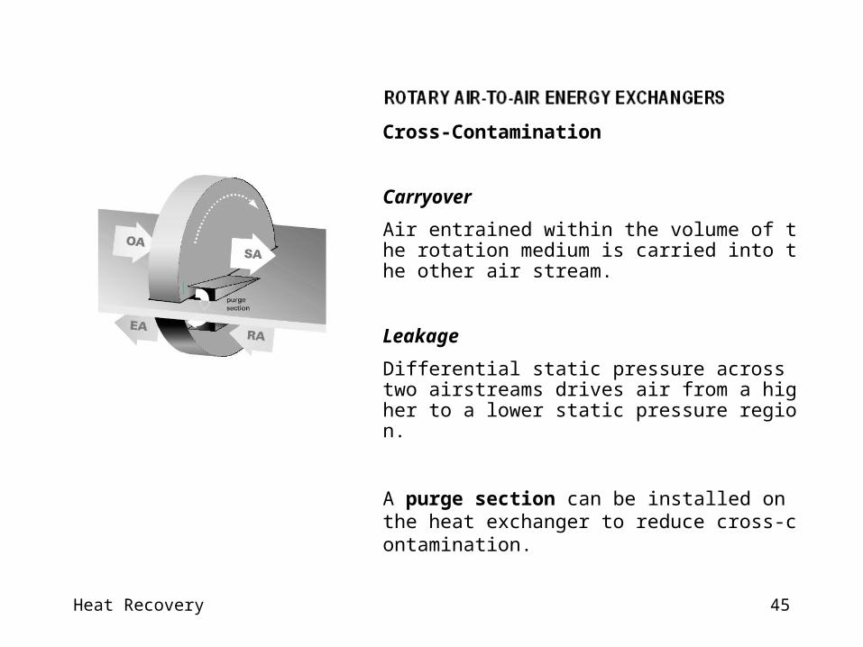
Cross-Contamination
Carryover
Air entrained within the volume of the rotation medium is carried into the other air stream.
Leakage
Differential static pressure across two airstreams drives air from a higher to a lower static pressure region.
A purge section can be installed on the heat exchanger to reduce cross-contamination.
Heat Recovery 46
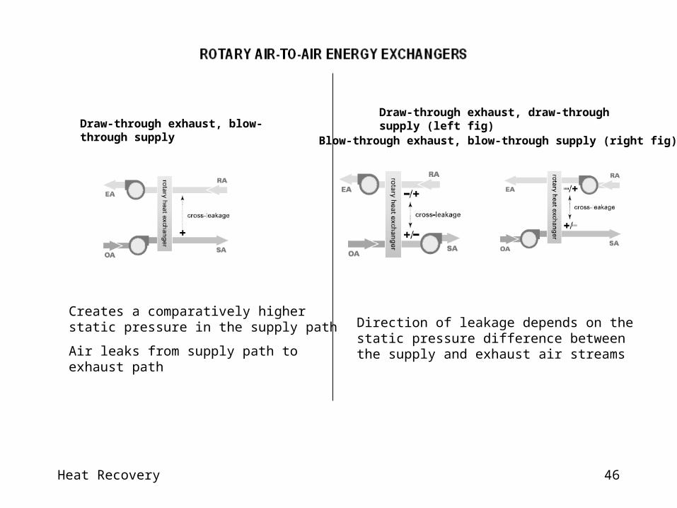
Creates a comparatively higher static pressure in the supply path
Air leaks from supply path to exhaust path
Draw-through exhaust, blow-through supplyDraw-through exhaust, draw-through supply (left fig)
Direction of leakage depends on the static pressure difference between the supply and exhaust air streams
Blow-through exhaust, blow-through supply (right fig)
Heat Recovery 47
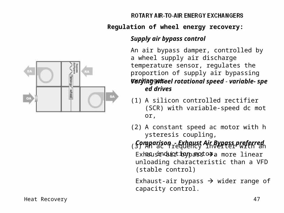
Varying wheel rotational speed - variable- speed drives
(1) A silicon controlled rectifier (SCR) with variable-speed dc motor,
(2) A constant speed ac motor with hysteresis coupling,
(3) An ac frequency inverter with an ac induction motor.
Regulation of wheel energy recovery:
Supply air bypass control
An air bypass damper, controlled by a wheel supply air discharge temperature sensor, regulates the proportion of supply air bypassing exchanger.
Comparison - Exhaust Air Bypass preferred
Exhaust-air bypass a more linear unloading characteristic than a VFD (stable control)
Exhaust-air bypass wider range of capacity control.
Heat Recovery 48
• Clean the medium when lint, dust, or other foreign materials build up.
• Media treated with a liquid desiccant for total heat recovery must not be wetted.
• Maintain drive motor and train according to the manufacturer’s recommendations.
• Speed control motors that have commutators and brushes require more frequent inspection and maintenance than do induction motors.
• Inspect wheels regularly for proper belt or chain tension.
• Refer to the manufacturer’s recommendations for spare and replacement parts.
Maintenance
Rotary enthalpy wheels require little maintenance.
The following maintenance procedures for best performance:

Heat Recovery 49
Heat Recovery 50
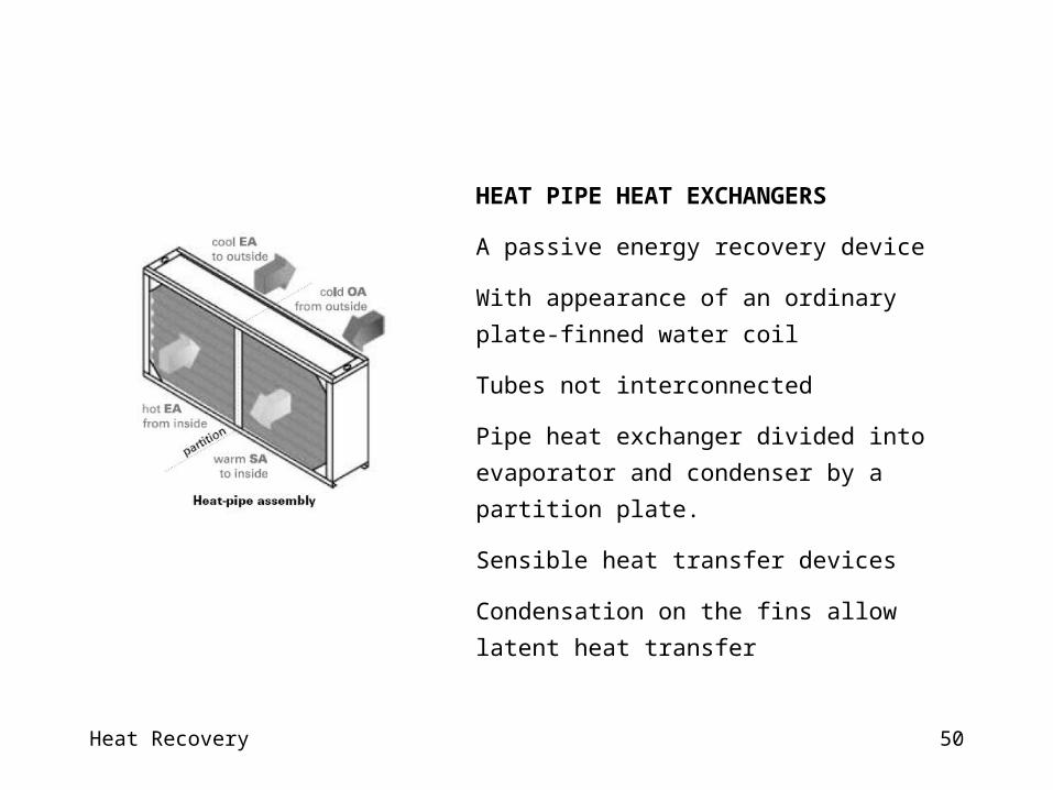
HEAT PIPE HEAT EXCHANGERS
A passive energy recovery device
With appearance of an ordinary plate-finned water coil
Tubes not interconnected
Pipe heat exchanger divided into evaporator and
condenser by a partition plate.
Sensible heat transfer devices
Condensation on the fins allow latent heat transfer

Heat Recovery 51
Heat pipe tubes are fabricated with an integral capillary
wick structure, evacuated, filled with a suitable working fluid and permanently sealed.
The working fluid is normally a refrigerant.
Fin designs include continuous corrugated plate fin, continuous plain fin, and spiral fins.
Modifying fin design and tube spacing changes pressure drop at a given face velocity.
Heat Recovery 52
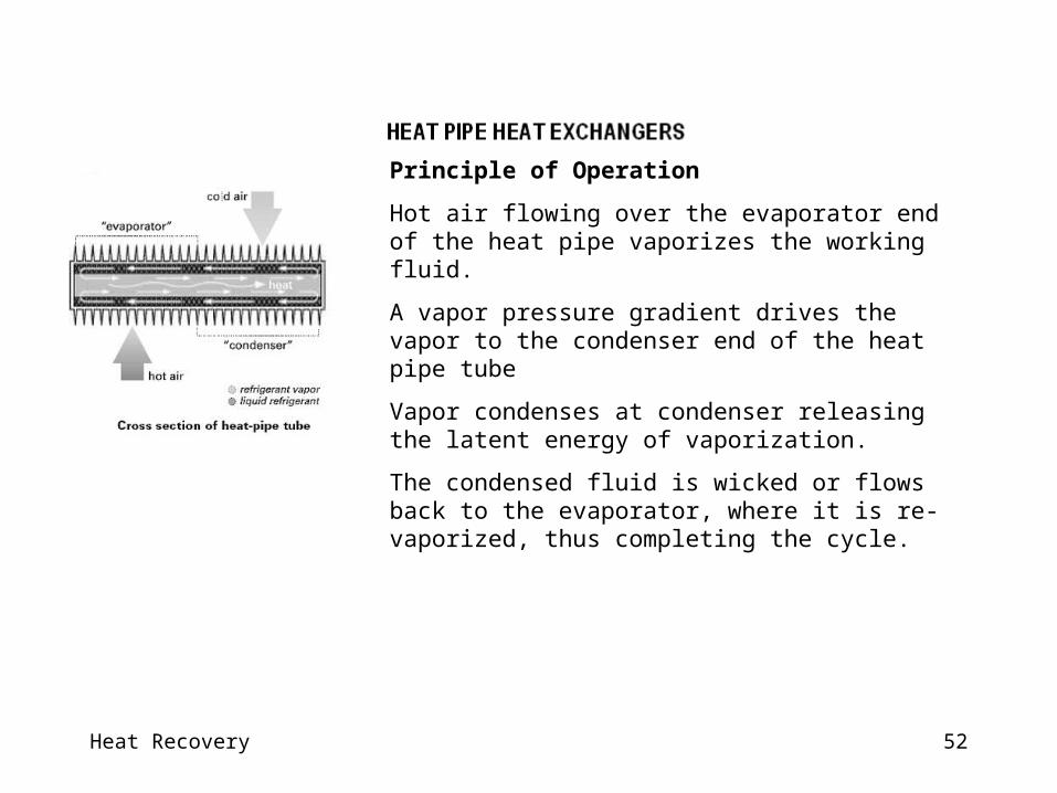
Principle of Operation
Hot air flowing over the evaporator end of the heat pipe vaporizes the working fluid.
A vapor pressure gradient drives the vapor to the condenser end of the heat pipe tube
Vapor condenses at condenser releasing the latent energy of vaporization.
The condensed fluid is wicked or flows back to the evaporator, where it is re-vaporized, thus completing the cycle.

Heat Recovery 53
Energy transfer in heat pipes is isothermal.
A small temperature drop through the tube wall, wick, and fluid medium.
Heat transfer capacity that is affected by :
- Wick design,
- Tube diameter,
- Working fluid,
- Tube orientation relative to horizontal.
Heat Recovery 54
Construction Materials
HVAC systems use copper or aluminum heat pipe tubes with aluminum fins.
Exhaust temperatures < 220°C : aluminum tubes and fins.
Protective coatings on finned tube for corrosive atmospheres(Coatings with negligible effect on thermal performance).
Steel tubes and fins for > 220°C with aluminized fins (prevent fin rusting).
Heat Recovery 55
Operating Temperature Range
The working fluid :
high latent heat of vaporization,
a high surface tension,
and a low liquid viscosity over the operating range;
Thermally stable at operating temperatures.
Non condensable gases from decomposition of thermal fluids deteriorate performance.
Heat Recovery 56
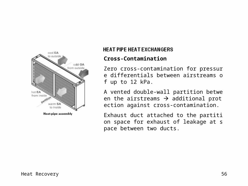
Cross-Contamination
Zero cross-contamination for pressure differentials between airstreams of up to 12 kPa.
A vented double-wall partition between the airstreams additional protection against cross-contamination.
Exhaust duct attached to the partition space for exhaust of leakage at space between two ducts.
Heat Recovery 57
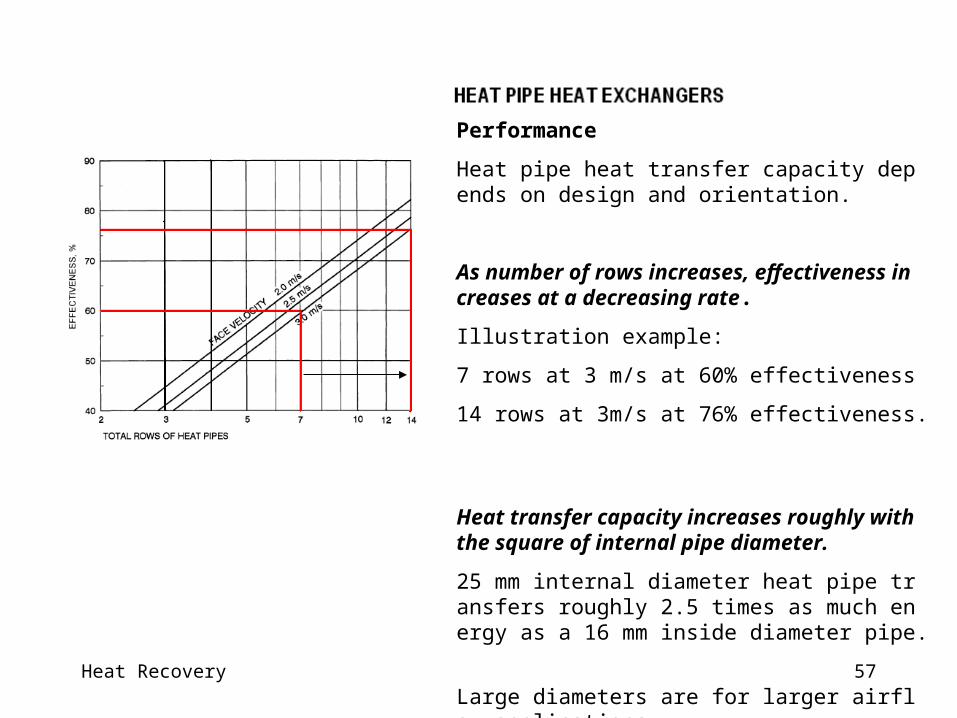
Performance
Heat pipe heat transfer capacity depends on design and orientation.
As number of rows increases, effectiveness increases at a decreasing rate.
Illustration example:
7 rows at 3 m/s at 60% effectiveness
14 rows at 3m/s at 76% effectiveness.
Heat transfer capacity increases roughly with the square of internal pipe diameter.
25 mm internal diameter heat pipe transfers roughly 2.5 times as much energy as a 16 mm inside diameter pipe.
Large diameters are for larger airflow applications.
Heat Recovery 58
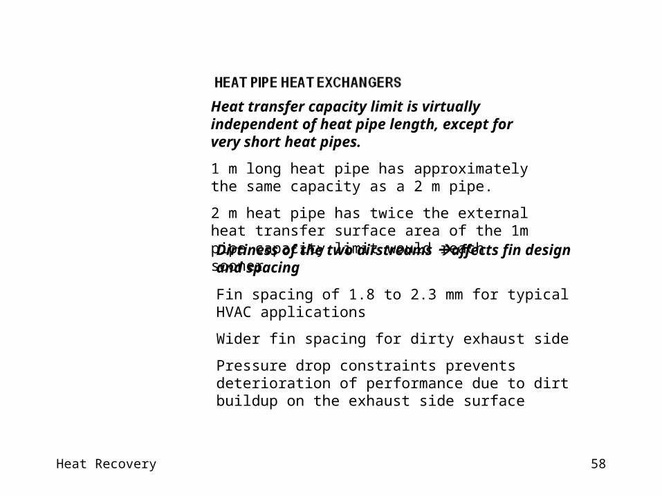
Heat transfer capacity limit is virtually independent of heat pipe length, except for very short heat pipes.
1 m long heat pipe has approximately the same capacity as a 2 m pipe.
2 m heat pipe has twice the external heat transfer surface area of the 1m pipe capacity limit would reach sooner.
Dirtiness of the two airstreams affects fin design and spacing
Fin spacing of 1.8 to 2.3 mm for typical HVAC applications
Wider fin spacing for dirty exhaust side
Pressure drop constraints prevents deterioration of performance due to dirt buildup on the exhaust side surface

Heat Recovery 59
Controls
Changing the slope (tilt) of a heat pipe controls the amount of heat it transfers.
Operating the heat pipe on a slope with the hot end below (or above) the horizontal improves (or retards) the condensate flow back to the evaporator end of the heat pipe.
This feature for regulating the effectiveness of the heat pipe heat exchanger.
Heat Recovery 60
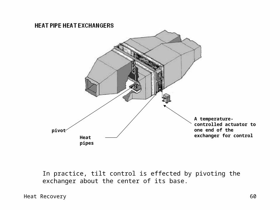
In practice, tilt control is effected by pivoting the exchanger about the center of its base.
A temperature-controlled actuator to one end of the exchanger for control
Heat pipes
pivot
Heat Recovery 61
Heat Recovery 62
Heat Recovery 63
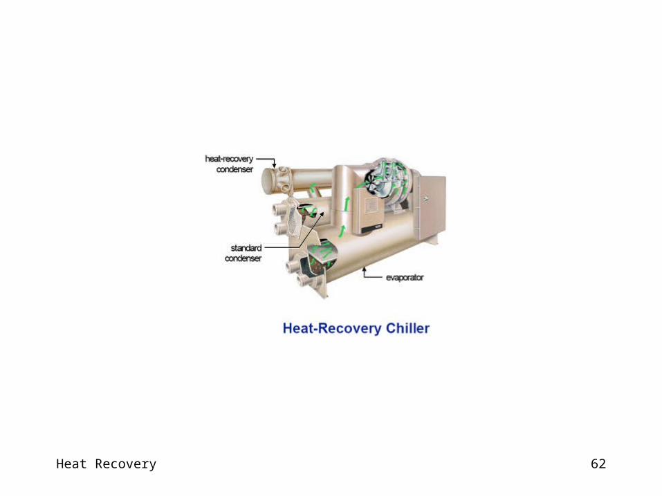
Heat recovery is the process of capturing the heat that is normally rejected from the chiller condenser.
Recovered heat from chiller for space heating, domestic water heating, or another process requirement.
Heat recovery chiller should be considered with simultaneous heating and cooling requirements.
Heat recovery chiller could also be considered for in facilities where the heat can be stored and used at a later time
Heat Recovery from Water Cooled Chiller

Heat Recovery 64
Heat recoveryHeat recovery can be applied to any type of water chiller.
Chiller with standard Condenser: Operating at higher condensing temperatures and recovering heat from the water leaving the condenser.
Separate condenser : Double-bundle water-cooled centrifugal chiller.
Desuperheater: Used in smaller chillers. A desuperheater is a device between compressor and condenser to recover heat from the hot refrigerant vapor.
Heat Recovery 65
Heat recovery in water-cooled centrifugal chillers - Double-Bundle heat-recovery chiller -1
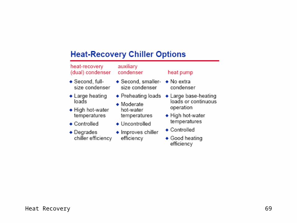
The dual-condenser or double-bundledual-condenser or double-bundle heat-recovery chiller contains a second, full-size condenser connecting to a separate hot-water loop.
Heat recovery chiller rejecting more heat and hence higher leaving-hot-water temperatures than an auxiliary condenser.
Varying the temperature or flow of water through the standard condenser control amount of heat rejected.
Chiller efficiency is degraded slightly in order to reach the higher condensing temperatures.
Heat Recovery 66
Heat recovery in water-cooled centrifugal chillers - Auxiliary-Condenser -2
An auxiliary-condenserauxiliary-condenser heat-recovery chiller makes use of a second, but smaller, condenser bundle.
It rejects less heat than dual-condenser chiller.
Leaving hot-water temperatures are also lower for preheating water at upstream of the primary heating equipment or water heater.
It requires no additional controls.
It improves chiller efficiency because of the extra heat-transfer surface for condensing.
Heat Recovery 67
A water source heat pump chiller is a standard chiller requiring no extra shells.
The useful heat produced in condenser, not evaporator.
The evaporator is connected to the chilled water loop, typically upstream of other chillers.
It only removes enough heat from the chilled water loop to handle the heating load served by the condenser water loop.
This application is useful in a multiple-chiller system where there is a base or year-round heating or process load, or where the quantity of heat required is significantly less than the cooling load.
The heating efficiency of a heat-pump chiller is the highest of any heat-producing device.
Heat recovery in water-cooled centrifugal chillers – Water Source heat pump chiller- 3

Heat Recovery 68
Heat Recovery 69
Heat Recovery 70
Heat Recovery Chiller Efficiency
There is usually an efficiency penalty associated with the use of heat recovery with a chiller.
The cost of this efficiency penalty, however, is typically much less than the energy saved by recovering the “free” heat.
The energy consumption of a heat-recovery chiller > a cooling-only chiller (higher pressure differential at which the compressor must operate).
Heat Recovery 71
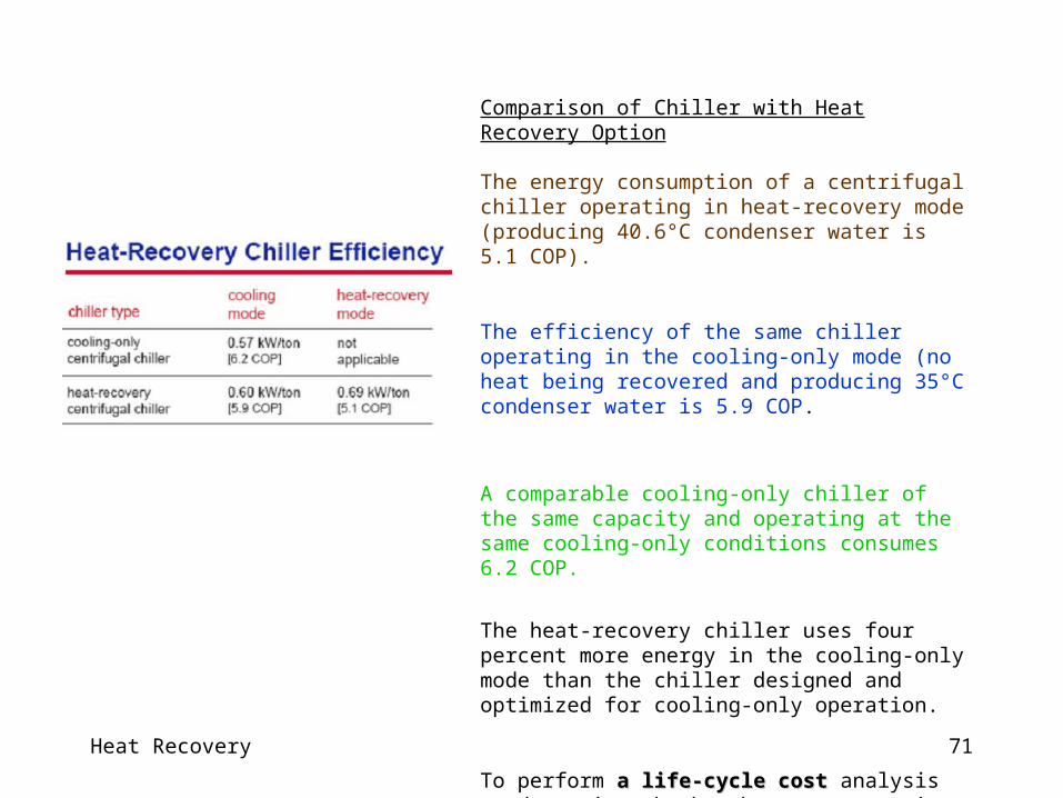
Comparison of Chiller with Heat Recovery Option
The energy consumption of a centrifugal chiller operating in heat-recovery mode (producing 40.6°C condenser water is 5.1 COP).
The efficiency of the same chiller operating in the cooling-only mode (no heat being recovered and producing 35°C condenser water is 5.9 COP.
A comparable cooling-only chiller of the same capacity and operating at the same cooling-only conditions consumes 6.2 COP.
The heat-recovery chiller uses four percent more energy in the cooling-only mode than the chiller designed and optimized for cooling-only operation.
To perform a life-cycle costa life-cycle cost analysis to determine whether heat recovery is a viable option.

Heat Recovery 72
The temperature or the flow of the water entering the standard condenser is modulated to meet the capacity required by the heat-recovery condenser.
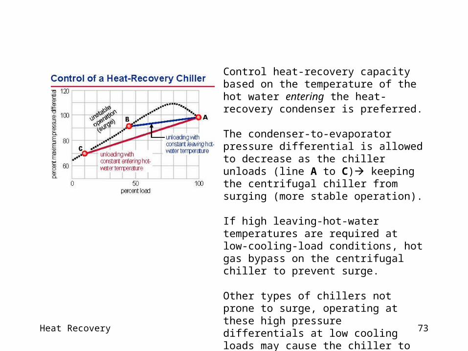
Control based on the temperature of the water leaving the heat-recovery condenser causes the condenser-to-evaporator pressure differential to remain relatively high at all loads (line A to B).
High pressure differentials at low cooling loads increases the risk of a centrifugal compressor operating in its unstable region (surge).
Heat Recovery 73
Control heat-recovery capacity based on the temperature of the hot water entering the heat-recovery condenser is preferred.
The condenser-to-evaporator pressure differential is allowed to decrease as the chiller unloads (line A to C) keeping the centrifugal chiller from surging (more stable operation).
If high leaving-hot-water temperatures are required at low-cooling-load conditions, hot gas bypass on the centrifugal chiller to prevent surge.
Other types of chillers not prone to surge, operating at these high pressure differentials at low cooling loads may cause the chiller to consume more energy than the recovering heat.