wain roy manual & hydraulic release rigid coupler 1/16yd
TRANSCRIPT

Wain Roy Manual & Hydraulic
Release Rigid Coupler
1/16yd, 1/8yd, 1/4yd,
1/2yd, 3/4yd, 1yd sizes
3028211 – Manual Part Number
DATE CODE: 8/18/2020 REV B
Woods Equipment
1962 Queenland Drive
Mosinee, WI 54455
1-800-848-3447
www.woodsequipment.com

Contents Dealer Information ......................................................................................................................................... 1
To The Dealer: ........................................................................................................................................... 1 To The Owner: ........................................................................................................................................... 1
Safety Rules ................................................................................................................................................... 2 Safety Rules Continued.................................................................................................................................. 3 Safety Information ......................................................................................................................................... 4
Attention! Become Alert! Your Safety Is Involved! ...................................................................................... 4 Coupler Diagram & Parts List ....................................................................................................................... 5 Xls Instructions And Parts List ...................................................................................................................... 6 Rigid Xls Coupler Daily Inspection ............................................................................................................... 7 Rigid Xls Coupler Daily Inspection Diagram ................................................................................................ 8
Hydraulic Release Xls Rigid Coupler ............................................................................................................ 8 A. System Description: .............................................................................................................................. 9
B. Coupler Retrofit................................................................................................................................... 10 C. Maintenance: ....................................................................................................................................... 11 D. Safety Precautions: .............................................................................................................................. 11
Hydraulic Xls Coupler Daily Inspection...................................................................................................... 13
Hyd. Rigid Xls Coupler Daily Inspection Diagram ..................................................................................... 14 General Hydraulic Layout Overview ........................................................................................................... 16
Hydraulic Component Installation ............................................................................................................... 17 Conversion From Rigid Coupler To Hydraulic Rigid Coupler ................................................................... 18
1/4yd Coupler........................................................................................................................................... 18
1/2yd Coupler........................................................................................................................................... 20
3/4yd Coupler........................................................................................................................................... 22
Bolt Torque Chart ........................................................................................................................................ 24 Bolt Size Chart ............................................................................................................................................. 25
Warranty ...................................................................................................................................................... 26

Page 1
DEALER INFORMATION To the Dealer:
Assembly and proper installation of this product is the responsibility of the WOODS dealer. Read manual
instructions and safety rules. Make sure all items on the Dealer’s Pre-Delivery and Delivery Check Lists in the
Operator’s Manual are completed before releasing equipment to the owner.
The dealer must complete the Warranty Registration included in this manual. Both dealer and customer must sign
the registration which certifies that all Dealer Check List items have been completed. The dealer is to return the
prepaid postage portion to WOODS, give one copy to the customer, and retain one copy. Note: Warranty credit is
subject to this form being completed and returned.
To the Owner:
Read this manual before operating your WOODS equipment. The information presented will prepare you to do a
better and safer job. Keep this manual handy for ready reference. Require all operators to read this manual carefully
and become acquainted with all the adjustment and operating procedures before attempting to operate.
Replacement manuals can be obtained from your dealer or, in the United States and Canada, by calling 1-800-319-
6637.
The equipment you have purchased has been carefully engineered and manufactured to provide dependable and
satisfactory use. Like all mechanical products, it will require cleaning and upkeep. Lubricate the unit as specified.
Observe all safety information in this manual and safety decals on the equipment.
For service, your authorized WOODS dealer has trained mechanics, genuine WOODS service parts, and the
necessary tools and equipment to handle all your needs.
Use only genuine WOODS service parts. Substitute parts will void the warranty and may not meet standards
required for safe and satisfactory operation. Record the model number and serial number of your equipment in the
spaces provided:
Model: _______________________________ Date of Purchase: _____________________
Serial Number: (see Safety Decal section for location) ____________________________________
Provide this information to your dealer to obtain correct repair parts.
Throughout this manual, the term IMPORTANT is used to indicate that failure to observe can cause damage to
equipment. The terms CAUTION, WARNING and DANGER are used in conjunction with the Safety-Alert Symbol,
(a triangle with an exclamation mark), to indicate the degree of hazard for items of personal safety.
This Safety-Alert Symbol indicates a hazard and means
ATTENTION! BECOME ALERT! YOUR SAFETY IS INVOLVED!
Indicates an imminently hazardous situation that, if not avoided, will result in death or serious injury.
WARNING Indicates an imminently hazardous situation that, if not avoided, will result in death or serious injury, and includes hazards that are exposed when guards are removed
CAUTION Indicates a potentially hazardous situation that, if not avoided, may result in minor injury or moderate injury.
IMPORTANT Indicates that failure to observe can cause damage to equiptment.
NOTE Indicates helpful information.
DANGER

Page 2
SAFETY RULES

Page 3
SAFETY RULES CONTINUED

Page 4
SAFETY INFORMATION ATTENTION! BECOME ALERT! YOUR SAFETY IS INVOLVED!
Replace Immediately If Damaged!
WARNING: The hitch pin with handle is NOT a lifting device. Do not
attempt to use any portion of the hitch pin or handle for lifting purposes. This could
cause the pin to fail and may result in the attachment to drop unexpectedly.
1 – Serial Tag (40313) On Coupler 2 – Attention Card (1006288) On Coupler
3 – Bucket Drop Decal (44846) In Cab
4 – XLS Adjustment (1003986) In Cab 5 – Bucket Strike (133043) In Cab

Page 5
COUPLER DIAGRAM & PARTS LIST
Ref # Part # Description
1 As Ordered Rigid Coupler (XLS or Original System)
2 Latch Pin Assembly
1/16yd 1024513 Pin Assembly
1/8yd 44772 Pin Assembly
1/4yd 147040 Pin Assembly
1/2yd 147054 Pin Assembly
3/4yd 147046 Pin Assembly
1 yd 108724 1yd is Hydraulic Pin Only
3 Locking Pin
1/16yd E056 Klik Pin
1/8yd 27542 Klik Pin
1/4yd 27542 Klik Pin
1/2yd 147007 PIN ASSEMBLY-LOCKING
3/4yd 147014 PIN ASSEMBLY-LOCKING
1yd N/A No locking pin for hydraulic pin setup
4 40313 Serial Tag

Page 6
Ref Description Qty
1/16 YD MINI
1/8 YD Mini
1/4 YD HD1
1/2 YD HD2 & HD3
3/4 YD HD4 HD5
1 YD HD6 HD7
Bucket Bearing Bar Assy 1 1024557 1007053 40379 40386 44007 44007 ----- -----
1 Bracket - XLS (Support - Short) A/R 1024517 1007056 40376 40388 40343 40343 0104105 0104105
2 Bearing Bar - XLS 1 1024522 1006208 40377 40389 40341 40341 0104106 0104106
3 Wear Plate - XLS 1 1024556 1006209 40378 40387 40345 40345 0104107 0104107
4 Shim - XLS (.010) A/R ----- 1006210 ----- ----- 40362 40362 ----- -----
4 Shim - XLS (.020) A/R 1024558 1006211 40381 44004 40361 40361 0104123 0104123
4 Shim - XLS (.040) A/R ----- ---- 40380 44003 ----- ----- 0104124 0104124
5 Screw – 3/8 NC x 1.25 2 S769x3 ---- ---- ---- ---- ---- ---- ----
5 Screw - 3/8 NC x 1.5" 2 ---- S769x4 ---- ---- ---- ---- ---- ----
5 Screw - 3/8 NC x 1.75" 2 ---- ---- S769x5 S769x5 ----- ----- ----- -----
5 Bolt - 1/2 NC x 2" 2 ---- ---- ----- ----- S637x7 S637x7 ----- -----
5 Bolt - 1/2 NC x 2 1/2" 2 ---- ---- ----- ----- ----- ----- S637x8 S637x8
6 Locknut - 3/8 NC 2 S340x5 S340x5 S340x5 S340x5 ----- ----- ----- -----
6 Locknut - 1/2 NC 2 ---- ---- ----- ----- S340x9 S340x9 S340x9 S340x9
Decal - Shim Adjustment 1 1003986 1003986 1003986 1003986 1003986 1003986 1003986 1003986
Not Shown Support - Long 1 ---- ---- ----- ----- 40344 1005105 0104104 40317
*A/R = As Required
XL
S IN
ST
RU
CT
ION
S A
ND
PA
RT
S L
IST
How to Shim the XLS Coupler System The XLS system is designed to make it easy to keep the bucket tight to the coupler. The system works by placing enough shims under the wear plate on the bucket to get rid of any movement between the bucket and coupler. When the bucket and coupler are first installed on a machine the XLS system should be shimmed tight. As the bucket is used it is normal for the bucket and shims to wear a bit; at this time, it is necessary to put more shims under the wear plate. Enough shims should be used so that the hand pin is just able to fit and slide freely into the bucket and coupler. A rubber mallet may be used to start the hand pin after adjustment. Do not use a hammer or maul to drive the Latch Pin Assembly in place. This may cause damage or failure to the Latch Pin Assembly. Failure to properly shim the XLS system will result in premature bucket and coupler wear. "Support - Long" is a center brace that runs along the back sheet of the bucket and is welded to the
backside of the XLS Bracket. (Not Shown)
Pag
e 6

Page 7
RIGID XLS COUPLER DAILY INSPECTION
WARNING: Failure to follow these daily inspections could result in the attachment to drop
unexpectedly and may cause serious injury or death.
Below are inspections and general maintenance procedures that must be performed on a daily basis. For the
below instruction, see page 5 and page 8 for diagrams.
1. Visually check the bucket to make sure it’s held tight to the coupler. If the bucket becomes loose and
has the XLS system then add shims until the bucket is tight, see the instructions on How to Shim a XLS
(Page 6). The latch pin assembly (#2 on the Coupler Diagram Parts List) must slide through the bucket
and coupler without using force. If the bucket is an original system then check the coupler and flats to
see if there is excessive wear.
2. Visually check the latch pin assembly (#2 on the Coupler Diagram Parts List) for wear, damage, or
cracks in the weld or to the handle portion of the latch pin assembly. If the handle is worn to less than
80% of the original diameter, the pin assembly must be replaced immediately. If any other wear,
cracks, or damage the pin is found it is a safety hazard and must be replaced immediately.
3. Visually check the locking pin that holds the latch pin assembly in place (#2 & #3 on Coupler Diagram
& Parts List). The ring on the locking pin should snap over the end of the latch pin assembly. The
locking pin should have spring tension that will cause the ring to snap closed on its own. If this ring no
longer engages properly then the locking pin must be replaced to prevent the latch pin assembly from
falling out during operation. A latch pin assembly that isn’t working properly is a safety hazard and
must be replaced immediately.
4. Visually check the Rigid Coupler (#1 on the Coupler Diagram Parts List) for excessive wear, weld or
material fractures, and cracks in the hook area. If any wear, cracking, or fractures is found the coupler
must be removed from service immediately and replaced.

Page 8
RIGID XLS COUPLER DAILY INSPECTION DIAGRAM

Page 9
HYDRAULIC RELEASE XLS RIGID COUPLER (Woods Equipment Company. Patent No: 5,727,342)
A. System Description: Your new Wain-Roy, Inc. hydraulic quick coupler is simple! Only one hose runs up the boom and down
the dipper stick to a single acting cylinder in the coupler. The other end of this hose connects to a solenoid
valve that is mounted inside the vehicle frame near the equipment valve. A drain line runs from the
solenoid valve to a low pressure drain line or to the hydraulic tank. There is a wire that reaches from the
solenoid to a locking toggle switch in the cab. The simplicity of the system makes installation easy and
takes less time than other systems. Removing the mechanical portion inside the coupler is very simple and
can be accomplished using only the supplied spring removal bolt. No tools are required.
The new hydraulic quick coupler was designed with safety in mind! The system is spring apply, hydraulic
release. The cylinder actually pushes the pin out to retract. If there is a loss of either electrical or
hydraulic power, the pin will remain extended or if the pin is retracted when there is a loss of power,
the pin will extend automatically. In the "latch" switch position the solenoid is shut off and no
pressure can reach the pin cylinder. If there is a hydraulic failure due to solenoid leakage the drain line
would divert the pressure thus not allowing the pin to retract. In the "unlatch" switch position, the
solenoid is energized but still requires the bucket cylinder to be completely extended before enough
pressure reaches the pin cylinder in order to retract the pin. In this position, the Wain-Roy Inc. coupler
hooks are rolled inward thus assuring that the tool will not fall off. Also in this position, red lights and
a beeper sound device alerts the operator that the switch is in the activated position. The new hydraulic quick coupler is effective! The cylinder is in the retracted position during the
tool working period. Because the cylinder is retracted, the rod is not exposed to being damaged from rocks and sharp objects. The pin indicator readily shows whether the pin is fully inserted or not. The indicator can be viewed easily from the operator position. Since a non-hydraulic coupler can be so easily retrofitted, in the unlikely event of a component failure, the coupler can easily be converted back to the mechanical manual hand pin version with no lost down time! Parts are easy to clean and broken parts are simple to replace.

Page 10
B. Coupler Retrofit (This does not apply if you purchased the coupler with the hydraulic pin already installed)
a. Prepare the coupler:
Cut the slot in the bottom of the coupler per the figure supplied with your retrofit kit. On the larger sizes locate and weld the spring support to the formed plate in the coupler as shown. On smaller size versions, add the cylinder stop block to the latch collar. Paint bare areas in order to inhibit corrosion.
b. Spring and pin installation:
Screw the cylinder into the pin block until the rod
of the cylinder is flush with the pin block as shown
in figure 6. Screw the two cap screws in the block
to retain the cylinder. Insert the pin and cylinder
assembly into the coupler. Place the compressed
spring assembly into the pin block. Push the pin up
against the spring so that the top of the spring is
resting properly in the spring retainer on the
coupler. Clamp or tie the pin in this retracted
position. Turn on the machine, turn the latch
switch to the on (unlatch) position and slowly roll
the coupler forward, extending the bucket cylinder
to its full length. This will extend the coupler cylinder and compress the spring. Remove the now loose
retaining bolt from the end of the compressed spring. Turn off the switch (latched position) and the
system is in full operational condition see figure 7. Reposition the coupler hose to its best orientation to
accommodate the full motion of the bucket linkage.

Page 11
C. Maintenance:
WARNING: Do not proceed to operate the machine with a tool unless the pin is inserted into the tool latch bracket.
Personal injury and machine damage could result. Visibly verify that the pin is properly inserted in the tool latch bracket.
Note: Remember that the coupler hooks and the attachment top must not have clumps of dirt adhered to the surfaces. Dirt on the coupler must be removed.
Make sure all moving parts are clean and free of mud and rocks. Clean the parts with air pressure or water frequently in order to avoid malfunction due to excess buildup of debris that could inhibit the operation of the spring. Check that the hose and the sheathing on the hose are free of abrasion and wear.
D. Safety Precautions:
Located 133068 on Switch Box Locate 133067 in Cab, must be Visible to Operator WARNING: The spring comes compressed from the factory. Do not attempt to remove
the bolt until the spring assembly is installed in the coupler. Personal injury could result. _________________________________________________________________________
WARNING: Do not place any part of the body inside the coupler while someone is near the hydraulic controls, even if the machine is off.
Personal injury could result.
The spring and the cylinder are very powerful! Use extreme caution while servicing or installing the components inside the coupler.
________________________________________________________________________
WARNING: Do not place any part of the body inside the machine linkage while someone is near the hydraulic controls, even if the machine is off.
Personal injury could result

Page 12
_______________________________________________________________________
WARNING: The coupler must be latched properly before operating the equipment or personal injury and machine damage could result. The operator must visibly verify that the pin is inserted in the tool latch bracket. The switch box lights, and beeper are solely to remind the operator that the switch is in the energized position! The absence of the sound and the light does not mean that the coupler is latched properly!
__________________________________________________________________________
WARNING: If the lights or the buzzer fail to operate properly, replace the necessary component immediately. The absence of these components could cause a failure to notify the operator of an energized solenoid condition thus resulting in possible personal injury and machine damage.

Page 13
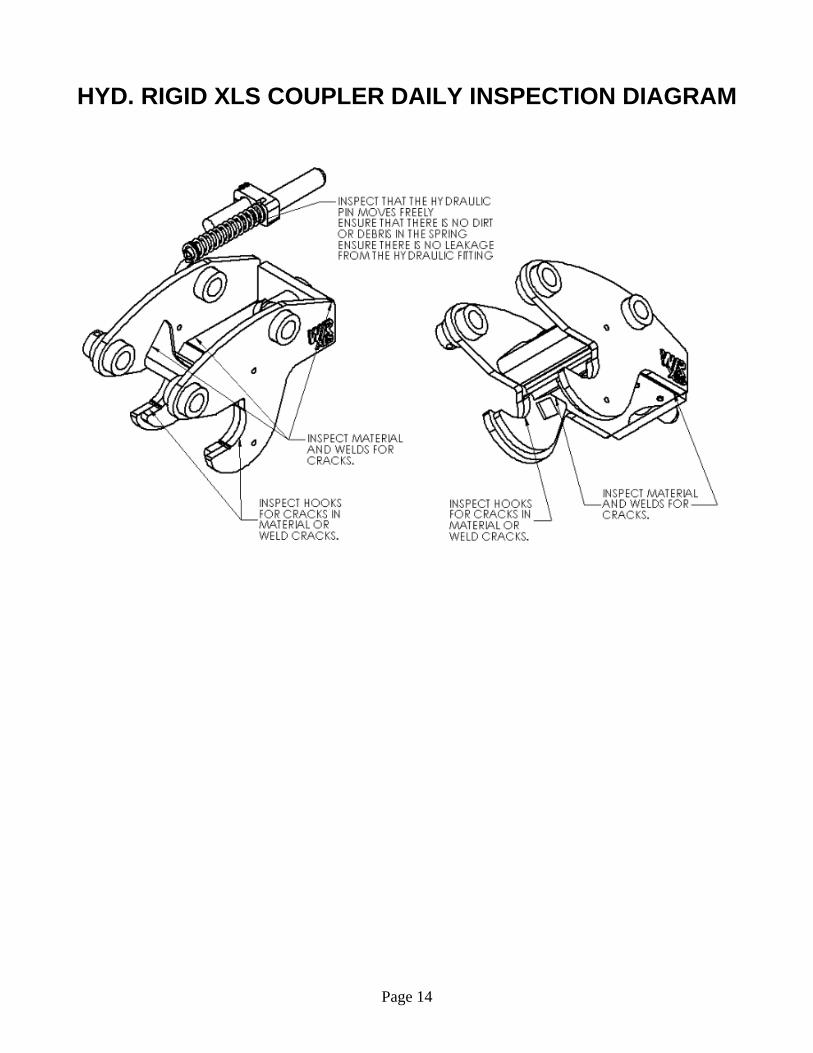
HYDRAULIC XLS COUPLER DAILY INSPECTION
WARNING: Failure to follow these daily inspections could result in the attachment to drop
unexpectedly and may cause serious injury or death.
Below are inspections and general maintenance procedures that must be performed on a daily basis. For the
below instruction, see page 5 and page 15 for diagrams.
1. Visually check the bucket to make sure it’s held tight to the coupler. If the bucket becomes loose and
has the XLS system then add shims until the bucket is tight, see the instructions on How to Shim a XLS
(Page 6). The pin assembly (#1 on the Hydraulic Coupler Diagram Parts List - page 15) must slide
through the bucket and coupler without using force.
2. Visually check the pin assembly (#1 on the Hydraulic Coupler Diagram Parts List- page 15) for wear,
damage, or cracks.
3. Visually check the Rigid Coupler (#1 on the Coupler Diagram Parts List- page 15) for excessive wear,
weld or material fractures, and cracks in the hook area. If any wear, cracking, or fractures is found the
coupler must be removed from service immediately and replaced.
Page 14
HYD. RIGID XLS COUPLER DAILY INSPECTION DIAGRAM

Page 15
HYDRAULIC PART BREAKDOWN
1/4 Yard 1/2 Yard 3/4 Yard QTY Description
Ref: Part #
1 004293 004293 004293 1 CYLINDER, HYD RGD CPL
2 108647 1080663 n/a BEARING PLATE
3 108641 108656 108666 1 PIN ASY
4 S124X17 S124X17 S124X17 2 SHCS 5/16 NC X 1-3/4 GR5 ZP
5 3035580 3035507 3035507 HYD. RGD-XLS PIN STOP KIT
6 162003 162004 162005 1 SPRING
7 108639 108701 108703 1 SPRING ASSEMBLY
7.1 108644 108659 108669 1 SPRING ROD ASSEMBLY
7.2 162003 162004 162005 1 SPRING
7.3 S635X9 2290 90001237 1 BOLT HH 1/2 NC X 3 GR5
7.4 n/a n/a 108672 1 SPRING KEEPER

Page 16
GENERAL HYDRAULIC LAYOUT OVERVIEW
NUMBER PART NUMBER DESCRIPTION
1 SEE ORDER VALVE (12v / 24v)
2 SEE ORDER SWITCH BOX
3 SEE ORDER WIRE (25 ft)
4 SEE ORDER ADAPTER
5 SEE ORDER 90° ELBOW
6 SEE ORDER HOSE

Page 17
HYDRAULIC COMPONENT INSTALLATION
Each Hydraulic kit has its own installation manual specific for the OEM machine, below is a summary of the kit
install.
1. Mount the solenoid valve (1) to the boom above the bucket cylinder. Be sure to measure the hose
included (6) to ensure the valve is positioned close enough to allow slack for bucket curl. (Note: the
valve can be mounted anywhere however the hose (6) provided is intended to be used with the valve
mounted near the bucket cylinder. A new hose would have to be provided by the dealer if the valve
location is to be moved.)
2. Attach item 5 to the coupler valve (1) as shown above. Attach item 4 to the coupler cylinder as shown
above.
3. With the two fittings in place (4 & 5) the Hose (6) can now be attached between the valve and coupler
hydraulic cylinder.
4. Determine a suitable location in the cab for installing the switch box (2) that is not part of the R.O.P.S.
structure. Remove the four screws in the cover of the switch box (2). Drill two holes 2-1/2” apart for
mounting the box. Use self-tapping screws. Mount the box and replace the cover.
5. Use the wire (3) provided to complete the rest of the wiring as shown in the hydraulic and wiring
diagram below:

Page 18
CONVERSION FROM RIGID COUPLER TO HYDRAULIC RIGID COUPLER
1/4YD Coupler
Required rework kit: 108706 • Please contact your Dealer for the correct hydraulic Kit (kits include but not limited to: Switch box and
Valve box assemblies, hoses and fittings) to fit your machine.
• Use of a kit not supplied by your Woods Dealer may void the warranty of the coupler and rework kit and
may cause injury or death.
Before you convert your Wain Roy Rigid XLS coupler to a hydraulic rigid coupler, please ensure you have all
required parts and have read instructions below prior to installing the hydraulic pin assembly and coupler
rework kit.
For couplers with a serial number prior to (s/n) 204086:
• Refer to print: 108693 supplied with the rework kit (The print supplied is a larger than the details below)
• You must extend the existing slot in the coupler spreader plate to the given dimensions shown below.
• You must drill (4ea) 7/16” holes in the coupler spreader plate to the given dimensions below.
• If the unit was built prior to 1998, you must cut a notch as shown in the “front” bent spreader plate
• You must bolt the HYD RGD-XLS PIN STOP KIT to the coupler. This kit is to be used when (and or if)
you revert back to a non-Hyd coupler and should be located in the center of the coupler.
• Locate and weld the supplied Bearing Ext. Plate (108647) as shown below.
Drilling / Milling for Slot – Welding Gusset Drilling for Pin Stop kit

Page 19
Locating Pin Stop Kit when Hyd. Pin is used Locating Pin Stop Kit when using Manual Pin
For couplers with a serial number after to (s/n) 204086:
• You must remove the existing pin stop
• Locate and weld the supplied Bearing Ext. Plate (108647) as shown below.
Removing Pin Stop – Welding Gusset Locating Pin Stop Kit when using Manual Pin

Page 20
1/2YD Coupler
Required rework kit: 108707 • Please contact your Dealer for the correct hydraulic Kit (kits include but not limited to: Switch box and
Valve box assemblies, hoses and fittings) to fit your machine.
• Use of a kit not supplied by your Woods Dealer may void the warranty of the coupler and rework kit and
may cause injury or death.
Before you convert your Wain Roy Rigid XLS coupler to a hydraulic rigid coupler, please ensure you have all
required parts and have read instructions below prior to installing the hydraulic pin assembly and coupler
rework kit.
For couplers with a serial number prior to (s/n) 204086:
• Refer to print: 108694 supplied with the rework kit (The print supplied is a larger than the details below)
• You must extend the existing slot in the coupler spreader plate to the given dimensions shown below.
• You must drill (4ea) 7/16” holes in the coupler spreader plate to the given dimensions below.
• You must bolt the HYD RGD-XLS PIN STOP KIT to the coupler. This kit is to be used when (and or if)
you revert back to a non-Hyd coupler and should be located in the center of the coupler.
• Locate and weld the supplied Bearing Ext. Plate (108663) and Mounting plate (108664) as shown
below.
Drilling / Milling for Slot – Welding Gusset Drilling for Pin Stop kit

Page 21
Locating Pin Stop Kit when Hyd. Pin is used Locating Pin Stop Kit when using Manual Pin
For couplers with a serial number after to (s/n) 204086:
• You must remove the existing pin stop
• Locate and weld the supplied Bearing Ext. Plate (108663) and Mounting plate (108664) as shown
below.
Removing Pin Stop – Welding Gusset Locating Pin Stop Kit when using Manual Pin

Page 22
3/4YD Coupler
Required rework kit: 108708
• Please contact your Dealer for the correct hydraulic Kit (kits include but not limited to: Switch box and
Valve box assemblies, hoses and fittings) to fit your machine.
• Use of a kit not supplied by your Woods Dealer may void the warranty of the coupler and rework kit and
may cause injury or death.
Before you convert your Wain Roy Rigid XLS coupler to a hydraulic rigid coupler, please ensure you have all
required parts and have read instructions below prior to installing the hydraulic pin assembly and coupler
rework kit.
For couplers with a serial number prior to (s/n) 204086:
• Refer to print: 108695 supplied with the rework kit. (The print supplied is a larger than the details
below)
• You must extend the existing slot in the coupler spreader plate to the given dimensions shown below.
• You must drill (4ea) 7/16” holes in the coupler spreader plate to the given dimensions below.
• You must bolt the HYD RGD-XLS PIN STOP KIT to the coupler. This kit is to be used when (and or if)
you revert back to a non-Hyd coupler and should be located in the center of the coupler.
• Locate and weld the supplied gusset (108673) as shown below.
Drilling / Milling for Slot – Welding Gusset Drilling for Pin Stop kit
Locating Pin Stop Kit when Hyd. Pin is used Locating Pin Stop Kit when using Manual Pin

Page 23
For couplers with a serial number after to (s/n) 204086:
• You must remove the existing pin stop
• Locate and weld the supplied gusset (108673) as shown below.
Removing Pin Stop – Welding Gusset Locating Pin Stop Kit when using Manual Pin

Page 24
BOLT TORQUE CHART

Page 25
BOLT SIZE CHART

Page 26
WARRANTY