w n e w courtesy of the laboratories of jeff w. lichtman ... · of heat and vibration and improve...
TRANSCRIPT
NEW
NEW
NEW
N E W
High-Performance Laser Scanning Microscope for Live Cell Imaging Combining Accuracy, Sensitivity and Laser Stimulation
Biological Confocal Laser Scanning Microscope
FV1200FLUOVIEW
Shinjuku Monolith, 3-1, Nishi Shinjuku 2-chome, Shinjuku-ku, Tokyo, Japan
Wendenstrasse 14-18, 20097 Hamburg, Germany
3500 Corporate Parkway, Center Valley, Pennsylvania 18034-0610, U.S.A.
491B River Vallay Road, #12-01/04 Valley Point Office Tower, Singapore 248373
21 Gilby Road, Mt. Waverley, VIC 3149, Melbourne, Australia
5301 Blue Lagoon Drive, Suite 290 Miami, FL 33126, U.S.A.
A8F, Ping An International Financial Center, No. 1-3, Xinyuan South Road, Chaoyang District, Beijing, China, 100027
• OLYMPUS CORPORATION is ISO14001 certified.• OLYMPUS CORPORATION is FM553994/ISO9001 certified.• Illumination devices for microscope have suggested lifetimes. Periodic inspections are required. Please visit our website for details.• This device is designed for use in industrial environments for the EMC performance (IEC61326-1 Class A device). Using it in a residential environment may affect other equipment in the environment. • All company and product names are registered trademarks and/or trademarks of their respective owners.• Images on the PC monitors are simulated.• Specifications and appearances are subject to change without any notice or obligation on the part of the manufacturer.
Printed in Japan M1761E-102012
Images are courtesy of the following institutions:"Brainbow" mouse brain stem Courtesy of the laboratories of Jeff W. Lichtman and Joshua R., Sanes Harvard University MCB Department and the Center for Brain Science (cover page)
Glandular and non-glandular leaf hairs (trichomes) of Pelargonium Courtesy of Dr. Ferhan Ayaydin, Cellular Imaging Laboratory, Biological Research Center, Szeged, Hungary (1, on the page 1)
Pilidium larva of Micrura alaskensis Courtesy of Dr. Svetlana Maslakova of the University of Washington and Dr. Mikhail V Matz of the Whitney Laboratory for Marine Bioscience, University of Florida (2, on the page 1)
CFP and YFP labelling of glycerol cleared fruit fly brain taken with 30x silicone objective Courtesy of Dr.Hidehiko Inagaki, Anderson lab, California Institute of Technology (3, on the page 1)
Cultured nerve cells derived from the mouse hippocampus Courtesy of Dr. Koji Ikegami, Dr. Mitsutoshi Setou, Molecular Geriatric Medicine, Mitsubishi Kagaku Institute of Life Sciences (5, on the page 1, lower, on the page 2)
Drosophila, Stage 14 Courtesy of Dr. Tetsuya Kojima, Laboratory of Innovational Biology, Department of Integrated Biosciences Graduate School of Frontier Sciences, University of Tokyo (top, on the page 2)
1 2
Reliability and Flexibility
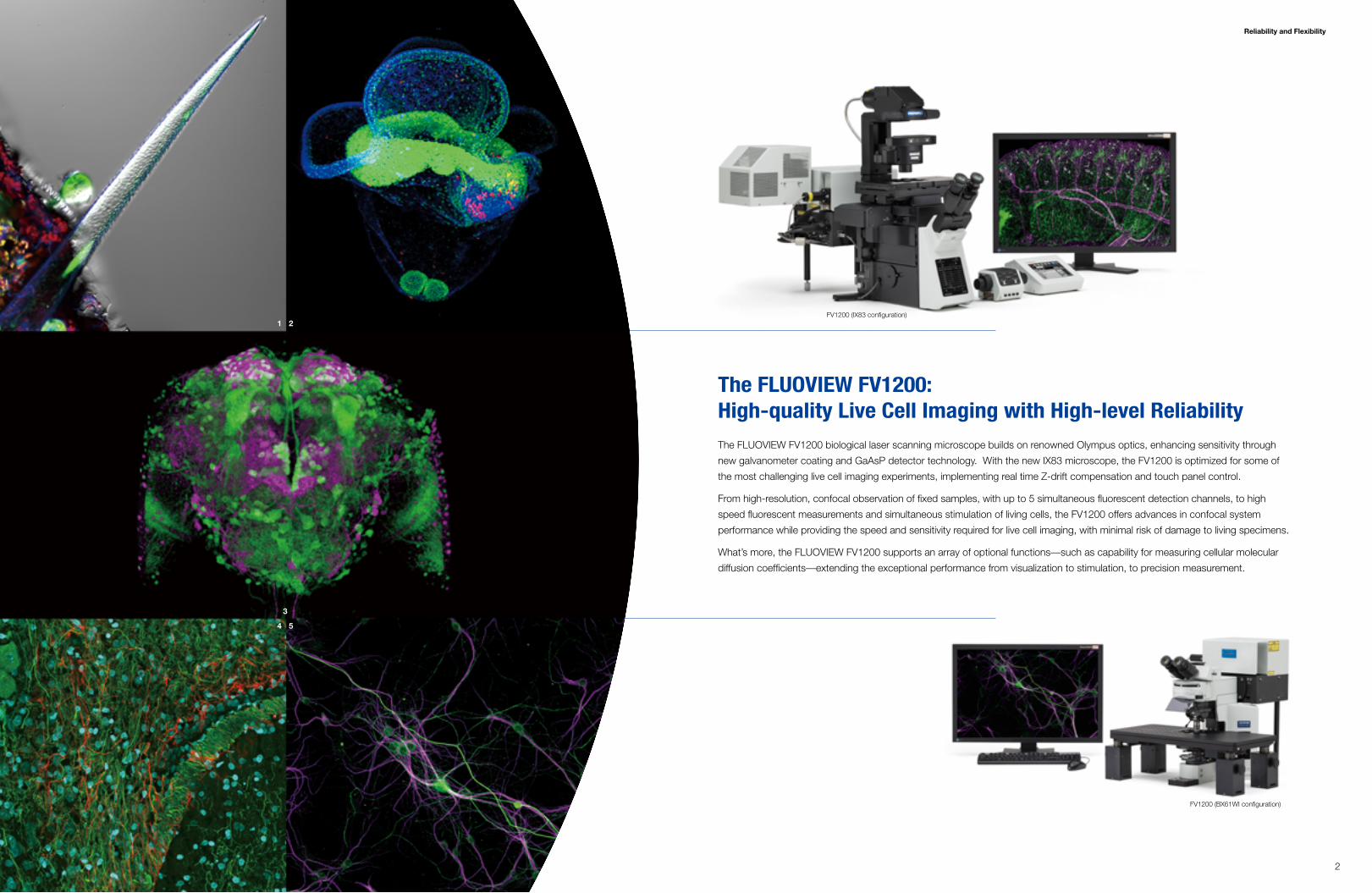
The FLUOVIEW FV1200: High-quality Live Cell Imaging with High-level ReliabilityThe FLUOVIEW FV1200 biological laser scanning microscope builds on renowned Olympus optics, enhancing sensitivity through
new galvanometer coating and GaAsP detector technology. With the new IX83 microscope, the FV1200 is optimized for some of
the most challenging live cell imaging experiments, implementing real time Z-drift compensation and touch panel control.
From high-resolution, confocal observation of fixed samples, with up to 5 simultaneous fluorescent detection channels, to high
speed fluorescent measurements and simultaneous stimulation of living cells, the FV1200 offers advances in confocal system
performance while providing the speed and sensitivity required for live cell imaging, with minimal risk of damage to living specimens.
What’s more, the FLUOVIEW FV1200 supports an array of optional functions—such as capability for measuring cellular molecular
diffusion coefficients—extending the exceptional performance from visualization to stimulation, to precision measurement.
1 2
4 5
3
FV1200 (IX83 configuration)
FV1200 (BX61WI configuration)
3 4
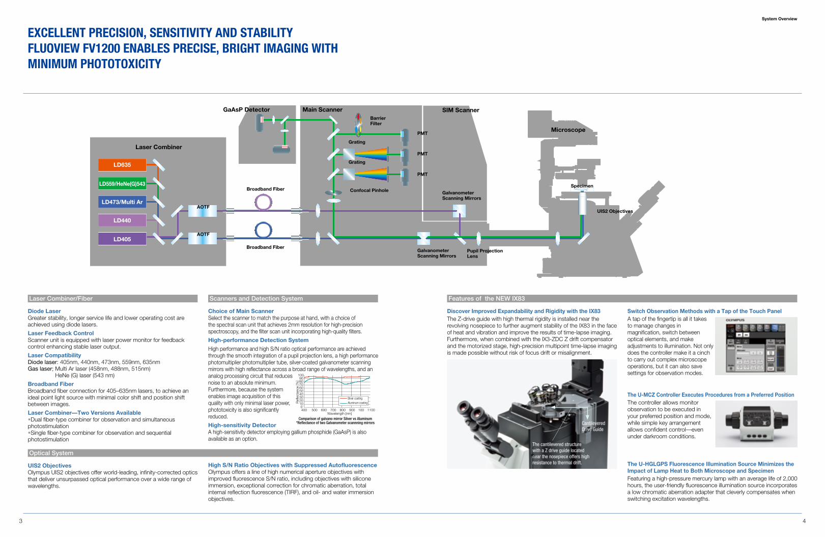
Diode LaserGreater stability, longer service life and lower operating cost are achieved using diode lasers.
Laser Feedback Control Scanner unit is equipped with laser power monitor for feedback control enhancing stable laser output.
Laser CompatibilityDiode laser: 405nm, 440nm, 473nm, 559nm, 635nmGas laser; Multi Ar laser (458nm, 488nm, 515nm)
HeNe (G) laser (543 nm)
Broadband FiberBroadband fiber connection for 405–635nm lasers, to achieve an ideal point light source with minimal color shift and position shift between images.
Laser Combiner—Two Versions Available•Dual fiber-type combiner for observation and simultaneous photostimulation•Single fiber-type combiner for observation and sequential photostimulation
Choice of Main ScannerSelect the scanner to match the purpose at hand, with a choice of the spectral scan unit that achieves 2mm resolution for high-precision spectroscopy, and the filter scan unit incorporating high-quality filters.
High-performance Detection System
High performance and high S/N ratio optical performance are achieved through the smooth integration of a pupil projection lens, a high performance photomultiplier photomultiplier tube, silver-coated galvanometer scanning mirrors with high reflectance across a broad range of wavelengths, and an analog processing circuit that reduces noise to an absolute minimum. Furthermore, because the system enables image acquisition of this quality with only minimal laser power, phototoxicity is also significantly reduced.
High-sensitivity DetectorA high-sensitivity detector employing gallium phosphide (GaAsP) is also available as an option.
UIS2 ObjectivesOlympus UIS2 objectives offer world-leading, infinity-corrected optics that deliver unsurpassed optical performance over a wide range of wavelengths.
Discover Improved Expandability and Rigidity with the IX83The Z-drive guide with high thermal rigidity is installed near the revolving nosepiece to further augment stability of the IX83 in the face of heat and vibration and improve the results of time-lapse imaging. Furthermore, when combined with the IX3-ZDC Z drift compensator and the motorized stage, high-precision multipoint time-lapse imaging is made possible without risk of focus drift or misalignment.
The U-HGLGPS Fluorescence Illumination Source Minimizes the Impact of Lamp Heat to Both Microscope and SpecimenFeaturing a high-pressure mercury lamp with an average life of 2,000 hours, the user-friendly fluorescence illumination source incorporates a low chromatic aberration adapter that cleverly compensates when switching excitation wavelengths.
The U-MCZ Controller Executes Procedures from a Preferred PositionThe controller allows monitor observation to be executed in your preferred position and mode, while simple key arrangement allows confident control—even under darkroom conditions.
LD635
LD559/HeNe(G)543
LD473/Multi Ar
LD405
LD440
AOTF
AOTF
Broadband Fiber
Pupil Projection Lens
UIS2 Objectives
Specimen
Galvanometer Scanning Mirrors
Main Scanner SIM Scanner
Microscope
Laser Combiner
GaAsP Detector
Broadband Fiber
Confocal Pinhole
Grating
Grating
PMT
PMT
PMT
Barrier Filter
Galvanometer Scanning Mirrors
Cantilevered Drive Guide
The cantilevered structure with a Z drive guide located near the nosepiece offers high resistance to thermal drift.
Laser Combiner/Fiber Features of the NEW IX83Scanners and Detection System
Optical System
High S/N Ratio Objectives with Suppressed AutofluorescenceOlympus offers a line of high numerical aperture objectives with improved fluorescence S/N ratio, including objectives with silicone immersion, exceptional correction for chromatic aberration, total internal reflection fluorescence (TIRF), and oil- and water immersion objectives.
400 500 600 700 800 900 100 1100
1009080706050403020100
Wavelength [nm]
Silver coatingAluminum coatingR
efle
ctan
ce [%
]
Comparison of galvano mirror Silver vs Aluminum*Reflectance of two Galvanometer scannning mirrors
System Overview
ExCELLEnT PRECIsIOn, sEnsITIVITy and sTabILITy FLUOVIEW FV1200 EnabLEs PRECIsE, bRIgHT ImagIng WITH mInImUm PHOTOTOxICITy
Switch Observation Methods with a Tap of the Touch PanelA tap of the fingertip is all it takes to manage changes in magnification, switch between optical elements, and make adjustments to illumination. Not only does the controller make it a cinch to carry out complex microscope operations, but it can also save settings for observation modes.
High Sensitivity Detection
5 6
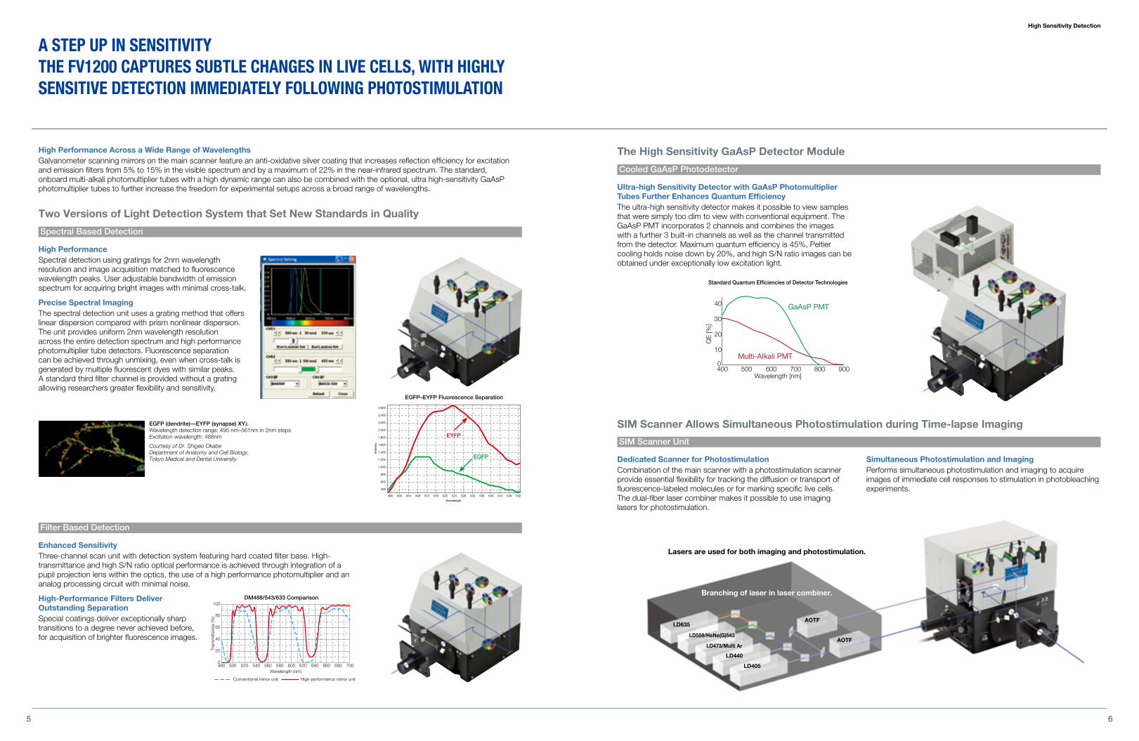
High PerformanceSpectral detection using gratings for 2nm wavelength resolution and image acquisition matched to fluorescence wavelength peaks. User adjustable bandwidth of emission spectrum for acquiring bright images with minimal cross-talk.
Precise Spectral ImagingThe spectral detection unit uses a grating method that offers linear dispersion compared with prism nonlinear dispersion. The unit provides uniform 2nm wavelength resolution across the entire detection spectrum and high performance photomultiplier tube detectors. Fluorescence separation can be achieved through unmixing, even when cross-talk is generated by multiple fluorescent dyes with similar peaks. A standard third filter channel is provided without a grating allowing researchers greater flexibility and sensitivity.
Enhanced SensitivityThree-channel scan unit with detection system featuring hard coated filter base. High- transmittance and high S/N ratio optical performance is achieved through integration of a pupil projection lens within the optics, the use of a high performance photomultiplier and an analog processing circuit with minimal noise.
High-Performance Filters Deliver Outstanding Separation Special coatings deliver exceptionally sharp transitions to a degree never achieved before, for acquisition of brighter fluorescence images.
EGFP (dendrite)—EYFP (synapse) XYλ Wavelength detection range: 495 nm–561nm in 2nm steps Excitation wavelength: 488nm
Courtesy of Dr. Shigeo Okabe Department of Anatomy and Cell Biology, Tokyo Medical and Dental University
480 500 520 540 560 580 600 620 640 660 680 700Wavelength (nm)
Tran
smitt
ance
(%)
0
20
40
60
80
100
Conventional mirror unit High-performance mirror unit
DM488/543/633 Comparison
496 500 504 508 512 516 520 524
Wavelength
Inte
nsity
528 532 536 540 544 548 552
400
600
800
1,000
1,200
1,400
1,600
1,800
2,000
2,200
2,400
2,600
EGFP–EYFP Fluorescence Separation
EYFP
EGFP
Two Versions of Light Detection System that Set New Standards in Quality
High Performance Across a Wide Range of WavelengthsGalvanometer scanning mirrors on the main scanner feature an anti-oxidative silver coating that increases reflection efficiency for excitation and emission filters from 5% to 15% in the visible spectrum and by a maximum of 22% in the near-infrared spectrum. The standard, onboard multi-alkali photomultiplier tubes with a high dynamic range can also be combined with the optional, ultra high-sensitivity GaAsP photomultiplier tubes to further increase the freedom for experimental setups across a broad range of wavelengths.
Spectral Based Detection
SIM Scanner Unit
Cooled GaAsP Photodetector
Filter Based Detection
SIM Scanner Allows Simultaneous Photostimulation during Time-lapse Imaging
The High Sensitivity GaAsP Detector Module
Ultra-high Sensitivity Detector with GaAsP Photomultiplier Tubes Further Enhances Quantum EfficiencyThe ultra-high sensitivity detector makes it possible to view samples that were simply too dim to view with conventional equipment. The GaAsP PMT incorporates 2 channels and combines the images with a further 3 built-in channels as well as the channel transmitted from the detector. Maximum quantum efficiency is 45%, Peltier cooling holds noise down by 20%, and high S/N ratio images can be obtained under exceptionally low excitation light.
a sTEP UP In sEnsITIVITyTHE FV1200 CaPTUREs sUbTLE CHangEs In LIVE CELLs, WITH HIgHLy sEnsITIVE dETECTIOn ImmEdIaTELy FOLLOWIng PHOTOsTImULaTIOn
GaAsP PMT
Multi-Alkali PMT
400 500 600 700 800 900
40
30
20
10
0
Wavelength [nm]
QE
[%]
Standard Quantum Efficiencies of Detector Technologies
Dedicated Scanner for PhotostimulationCombination of the main scanner with a photostimulation scanner provide essential flexibility for tracking the diffusion or transport of fluorescence-labeled molecules or for marking specific live cells. The dual-fiber laser combiner makes it possible to use imaging lasers for photostimulation.
Simultaneous Photostimulation and ImagingPerforms simultaneous photostimulation and imaging to acquire images of immediate cell responses to stimulation in photobleaching experiments.
Branching of laser in laser combiner.
Lasers are used for both imaging and photostimulation.
LD440
LD405
LD635AOTF
AOTFLD473/Multi Ar
LD559/HeNe(G)543
Accuracy
7 8
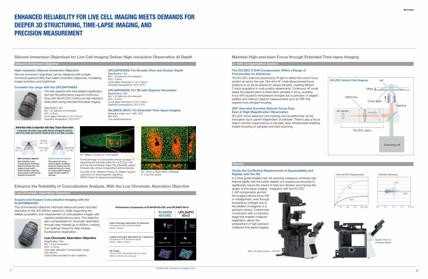
Silicone Immersion Objectives for Live Cell Imaging Deliver High-resolution Observation At Depth
High-resolution Silicone Immersion ObjectiveSilicone immersion objectives can be designed with a larger numerical aperture (NA) than water immersion objectives, increasing image resolution and brightness.
Complete the range with the UPLSAPO40XSThis new objective with intermediate magnification and high NA performance supports continuous focus with the IX3-ZDC.Continuous high-resolution observation during extended time-lapse imaging.
UPLSAPO30XS: For Broader View and Greater DepthMagnification: 30x NA: 1.05 (silicone oil immersion) W.D.: 0.8mm Cover glass thickness: 0.13–0.19mm Operation temperature: 23ºC–37ºC
Magnification: 40x NA: 1.25 (silicone oil immersion) W.D.: 0.3mm Cover glass thickness: 0.15–0.19 mm Operation temperature: 23ºC–37ºC
UPLSAPO60XS: For 3D with Superior ResolutionMagnification: 60xNA: 1.30 (silicone oil immersion)W.D.: 0.3mmCover glass thickness: 0.15–0.19mmOperation temperature: 23ºC–37ºC
SIL300CS-30CC: For Extended Time-lapse ImagingRefractive index: ne=1.406, 23ºCNet 30mlLow autofluorescence
Enhance the Reliability of Colocalization Analysis, With the Low Chromatic Aberration Objective
Acquire and Analyze Colocalization Imaging with the PLAPON60XOSCThis oil-immersion objective minimizes lateral and axial chromatic aberration in the 405-650nm spectrum, while supporting the reliable acquisition and measurement of colocalization images with
superior positional accuracy. The objective also compensates for chromatic aberration through near infrared up to 850nm, making it an optimal choice for near infrared fluorescence observation.
PLAPON60×OSC
UPLSAPO60×O
Axial chromatic aberration (Z direction)Compared for PSF fluorescent beads (405nm, 633nm)
Lateral chromatic aberration (X-Y direction) Compared for PSF fluorescent beads (405nm, 488nm, 633nm)
3D imageTubulin in Ptk2 cells labeled with two colors (405nm, 635nm) and compared
Approx. 0.5µm
Approx. 0µm
Approx. 0.1µm Approx. 0.2µm
Performance Comparison of PLAPON 60×OSC and UPLSAPO 60×O
XY: 466µm x 224µm (777x374pixel)
XY: 120µm x 90µm (800 x 600pixel) Z: 21µm (42 slices)
Water immersion objective Silicone immersion objective
Refractive Index is Important with deep Tissue Observation
Cover glassne≈1.52
Silicone oilne≈1.40
Waterne≈1.33
Samplene≈1.38
When working with a water immersion objective, the difference between the refractive index of the samples and water results in spherical aberration in deep tissue, causing resolution to deteriorate and fluorescence to become dim.
When working with a silicone immersion objective, the difference between the refractive index of the samples and silicone oil is minimal. So it achieves brighter fluorescence images with higher resolution for deep tissue.
In deep tissue observation, image quality depends on keeping the refractive index of the sample and immersion medium as close to each other as possible.
Confocal image of a Drosophila embryo at stage 11 expressing the tracheal maker trh-LacZ (Cy3, red) and the cell membrane maker DIg (Alexa488, green). Enlarged view shows invaginating tracheal placode.
Courtesy of Dr. Takefumi Kondo, Dr. Shigeo Hayashi, Laboratory for Morphogenetic Signaling, RIKEN Center for Developmental Biology
Low Chromatic Aberration ObjectiveMagnification: 60x NA: 1.4 (oil immersion) W.D.: 0.12mm Chromatic aberration compensation range: 405–650nm Optical data provided for each objective.
Maintain High-precision Focus through Extended Time-lapse Imaging
ZDC One-shot Function Detects Focus Fast, Even in High Magnification ObservationIX3-ZDC focus detection and tracking can be performed via the innovative touch panel independent of software. There’s also a focus search function supported by a cell-safe, near-infrared laser enabling instant focusing on samples and start scanning.
Tackle the Conflicting Requirements of Expandability and Rigidity with the IX3A Z-drive guide installed near the revolving nosepiece combines high thermal rigidity with the further stability of a wraparound structure to significantly reduce the impact of heat and vibration and improve the quality of time-lapse imaging. Integration with the IX3-ZDC Z drift compensator permits the imaging without focus drift or misalignment, even through temperature changes due to the addition of reagents or a perfusion device. Furthermore, combination with a motorized stage that enables multipoint registration, allows the achievement of high-precision multipoint time-lapse imaging.
Thermal Drift Displacement
IX83
0 50 100 150 200 (min)
IX81
Periodic Damping
0.0 0.5 1.0 1.5
IX83
IX81
2.0 (s)
The IX3-ZDC Z Drift Compensator Offers a Range of Functionality for AutofocusThe IX3-ZDC uses low phototoxicity IR light to detect the correct focus position as set by the user. One-shot AF mode allows several focus positions to be set as desired for deeper samples, enabling efficient Z-stack acquisition in multi-position experiments. Continuous AF mode keeps the desired plane of observation precisely in focus, avoiding focus drift caused by temperature changes due to perfusion or reagent addition and making it ideal for measurements such as TIRF that requires more stringent focusing.
Square Frame forIncreased Rigidity
Offset lens
IX3-ZDC optics
Cover glass
cell
Offset
AF sensor
Objective
Scanning unit
IX3-ZDC Optical Path Diagram
Low Chromatic Aberration Objective
Silicone Immersion Objective Z- drift Compensation System
Rigidity
EnHanCEd RELIabILITy FOR LIVE CELL ImagIng mEETs dEmands FOR dEEPER 3d sTRUCTURIng, TImE-LaPsE ImagIng, and PRECIsIOn mEasUREmEnT
*UPLSAPO40XS :Scheduled to be available on 2013.
IX83 : Two-deck System + IX3-ZDC
Applications
9 10
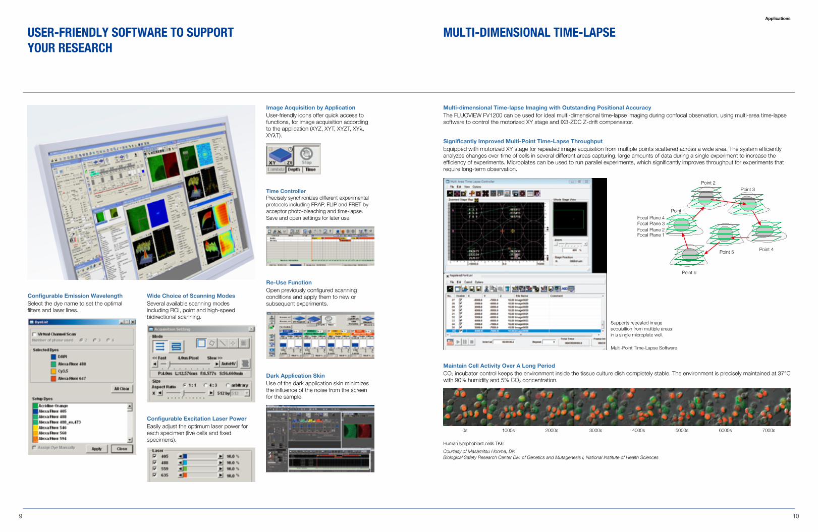
Time ControllerPrecisely synchronizes different experimental protocols including FRAP, FLIP and FRET by acceptor photo-bleaching and time-lapse. Save and open settings for later use.
Re-Use FunctionOpen previously configured scanning conditions and apply them to new or subsequent experiments.
Dark Application SkinUse of the dark application skin minimizes the influence of the noise from the screen for the sample.
Wide Choice of Scanning ModesSeveral available scanning modes including ROI, point and high-speed bidirectional scanning.
Configurable Excitation Laser PowerEasily adjust the optimum laser power for each specimen (live cells and fixed specimens).
Image Acquisition by ApplicationUser-friendly icons offer quick access to functions, for image acquisition according to the application (XYZ, XYT, XYZT, XYλ, XYλT).
Configurable Emission WavelengthSelect the dye name to set the optimal filters and laser lines.
UsER-FRIEndLy sOFTWaRE TO sUPPORT yOUR REsEaRCH
Significantly Improved Multi-Point Time-Lapse ThroughputEquipped with motorized XY stage for repeated image acquisition from multiple points scattered across a wide area. The system efficiently analyzes changes over time of cells in several different areas capturing, large amounts of data during a single experiment to increase the efficiency of experiments. Microplates can be used to run parallel experiments, which significantly improves throughput for experiments that require long-term observation.
Focal Plane 1Focal Plane 2Focal Plane 3Focal Plane 4
Point 1
Point 2Point 3
Point 4Point 5
Point 6
Multi-dimensional Time-lapse Imaging with Outstanding Positional AccuracyThe FLUOVIEW FV1200 can be used for ideal multi-dimensional time-lapse imaging during confocal observation, using multi-area time-lapse software to control the motorized XY stage and IX3-ZDC Z-drift compensator.
Maintain Cell Activity Over A Long PeriodCO2 incubator control keeps the environment inside the tissue culture dish completely stable. The environment is precisely maintained at 37°C with 90% humidity and 5% CO2 concentration.
0s 1000s 2000s 3000s 5000s 6000s 7000s4000s
Human lymphoblast cells TK6
Courtesy of Masamitsu Honma, Dir. Biological Safety Research Center Div. of Genetics and Mutagenesis I, National Institute of Health Sciences
mULTI-dImEnsIOnaL TImE-LaPsE
Multi-Point Time-Lapse Software
Supports repeated image acquisition from multiple areas in a single microplate well.
Applications
11 12
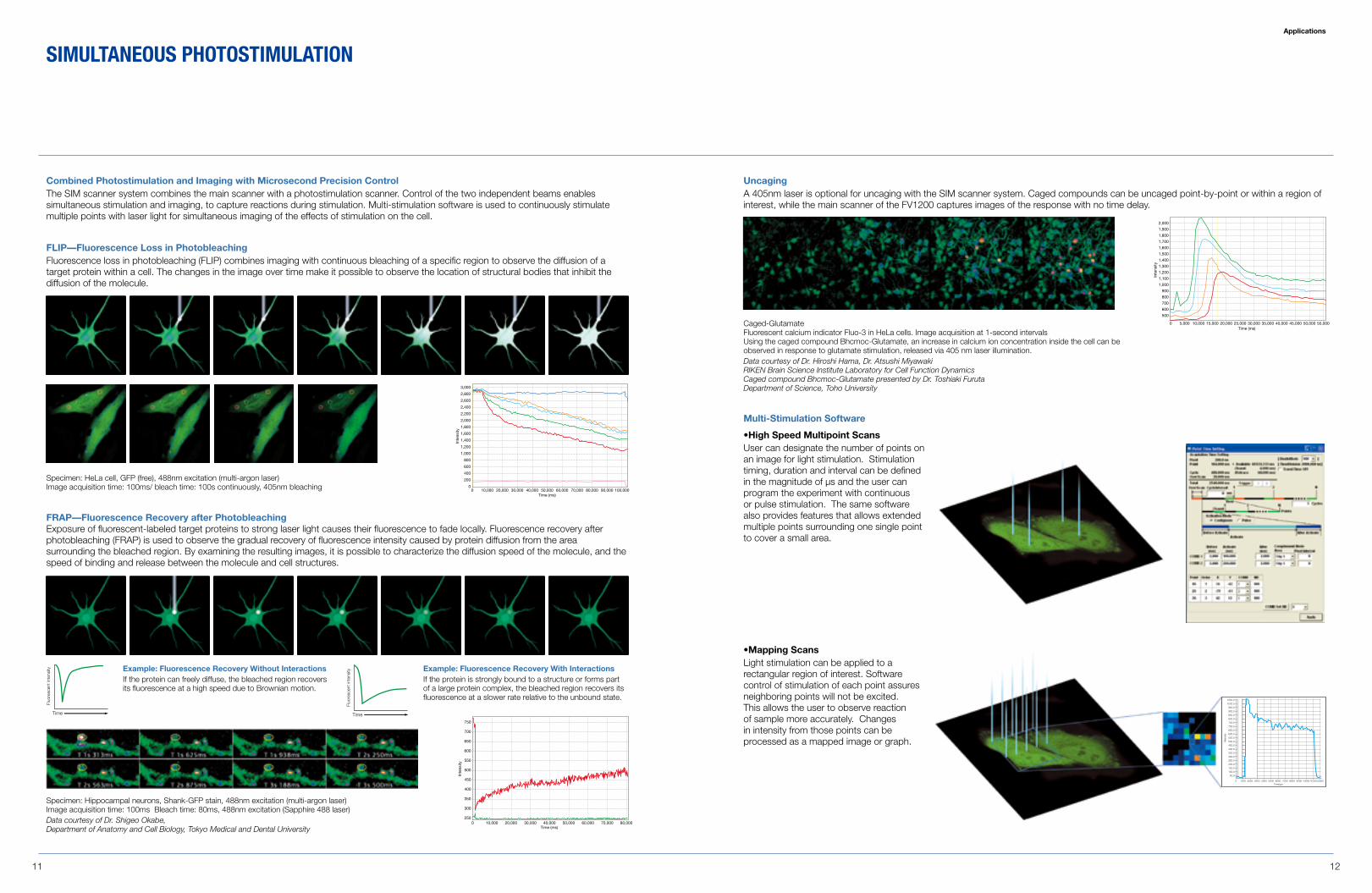
Caged-Glutamate Fluorescent calcium indicator Fluo-3 in HeLa cells. Image acquisition at 1-second intervals Using the caged compound Bhcmoc-Glutamate, an increase in calcium ion concentration inside the cell can be observed in response to glutamate stimulation, released via 405 nm laser illumination.Data courtesy of Dr. Hiroshi Hama, Dr. Atsushi Miyawaki RIKEN Brain Science Institute Laboratory for Cell Function Dynamics Caged compound Bhcmoc-Glutamate presented by Dr. Toshiaki Furuta Department of Science, Toho University
Example: Fluorescence Recovery Without InteractionsIf the protein can freely diffuse, the bleached region recovers its fluorescence at a high speed due to Brownian motion.
Example: Fluorescence Recovery With InteractionsIf the protein is strongly bound to a structure or forms part of a large protein complex, the bleached region recovers its fluorescence at a slower rate relative to the unbound state.
Time
Time
Fluo
resc
ent i
nten
sity
Fluo
resc
ent i
nten
sity
Time
Time
Fluo
resc
ent i
nten
sity
Fluo
resc
ent i
nten
sity
Specimen: HeLa cell, GFP (free), 488nm excitation (multi-argon laser)Image acquisition time: 100ms/ bleach time: 100s continuously, 405nm bleaching 0
0
200
400
600
800
1,000
1,200
1,400
1,600
1,800
2,000
2,200
2,400
2,600
2,800
3,000
10,000 20,000 30,000 40,000 50,000Time (ms)
60,000 70,000 80,000 90,000 100,000
Inte
nsity
0250
300
350
400
450
500
550
600
650
750
700
10,000 20,000 30,000 40,000 50,000Time (ms)
60,000 70,000 80,000
Inte
nsity
0 5,000 10,000 20,00015,000 30,00025,000 35,000Time (ms)
40,000 50,00045,000 55,000
500
600
700
800
900
1,000
1,100
1,200
1,300
1,400
1,500
1,600
1,700
1,800
1,900
2,000
Inte
nsity
00
200
400
600
800
1,000
1,200
1,400
1,600
1,800
2,000
2,200
2,400
2,600
2,800
3,000
10,000 20,000 30,000 40,000 50,000Time (ms)
60,000 70,000 80,000 90,000 100,000
Inte
nsity
0250
300
350
400
450
500
550
600
650
750
700
10,000 20,000 30,000 40,000 50,000Time (ms)
60,000 70,000 80,000
Inte
nsity
0 5,000 10,000 20,00015,000 30,00025,000 35,000Time (ms)
40,000 50,00045,000 55,000
500
600
700
800
900
1,000
1,100
1,200
1,300
1,400
1,500
1,600
1,700
1,800
1,900
2,000
Inte
nsity
Specimen: Hippocampal neurons, Shank-GFP stain, 488nm excitation (multi-argon laser) Image acquisition time: 100ms Bleach time: 80ms, 488nm excitation (Sapphire 488 laser)Data courtesy of Dr. Shigeo Okabe, Department of Anatomy and Cell Biology, Tokyo Medical and Dental University
Combined Photostimulation and Imaging with Microsecond Precision ControlThe SIM scanner system combines the main scanner with a photostimulation scanner. Control of the two independent beams enables simultaneous stimulation and imaging, to capture reactions during stimulation. Multi-stimulation software is used to continuously stimulate multiple points with laser light for simultaneous imaging of the effects of stimulation on the cell.
FLIP—Fluorescence Loss in PhotobleachingFluorescence loss in photobleaching (FLIP) combines imaging with continuous bleaching of a specific region to observe the diffusion of a target protein within a cell. The changes in the image over time make it possible to observe the location of structural bodies that inhibit the diffusion of the molecule.
UncagingA 405nm laser is optional for uncaging with the SIM scanner system. Caged compounds can be uncaged point-by-point or within a region of interest, while the main scanner of the FV1200 captures images of the response with no time delay.
Multi-Stimulation Software
FRAP—Fluorescence Recovery after PhotobleachingExposure of fluorescent-labeled target proteins to strong laser light causes their fluorescence to fade locally. Fluorescence recovery after photobleaching (FRAP) is used to observe the gradual recovery of fluorescence intensity caused by protein diffusion from the area surrounding the bleached region. By examining the resulting images, it is possible to characterize the diffusion speed of the molecule, and the speed of binding and release between the molecule and cell structures.
sImULTanEOUs PHOTOsTImULaTIOn
•High Speed Multipoint ScansUser can designate the number of points on an image for light stimulation. Stimulation timing, duration and interval can be defined in the magnitude of µs and the user can program the experiment with continuous or pulse stimulation. The same software also provides features that allows extended multiple points surrounding one single point to cover a small area.
0
50.0
100.0
150.0
200.0
250.0
300.0
350.0
400.0
450.0
500.0
550.0
600.0
650.0
700.0
750.0
800.0
850.0
900.0
950.0
1000.0
1050.0
1000 2000 3000 4000 5000 6000Time(µs)
Inte
nsity
7000 8000 9000 100001100012000
•Mapping ScansLight stimulation can be applied to a rectangular region of interest. Software control of stimulation of each point assures neighboring points will not be excited. This allows the user to observe reaction of sample more accurately. Changes in intensity from those points can be processed as a mapped image or graph.
13 14
Comparison of Diffusion Coefficients for EGFP Fusion Proteins Near to Cell Membranes and In CytoplasmRICS can be used to designate and analyze regions of interest based on acquired images. EGFP is fused at protein kinase C (PKC) for visualization, using live cells to analyze the translocation with RICS. The diffusion coefficient close to cell membranes was confirmed to be lower than in cytoplasm, after stimulation with phorbol myristate acetate (PMA). This is thought to be from the mutual interaction between PKC and cell membrane molecules in cell membranes. In addition to localization of molecules, RICS analysis can simultaneously determine changes in diffusion coefficient, for detailed analysis of various intracellular signaling proteins.
FRAP AnalysisThe Axelrod analytical algorithm is installed as a FRAP analysis method. The algorithm is used to calculate diffusion coefficients and the proportions of diffusing molecules.
point FCSRICSFRAP
> 100Diffusion constant (m2/s)
Capable range of measurement
~ 100 1 ~ 100 < 0.1 < 0.01 << 0.001
Small moleculesin solution
Proteinsin solution
Diffusion of proteins
in solution
Oligomers,aggregation
Proteintrafficking(endosytosis)
Lateral diffusionin cell membrane(membrane trafficking)
Analytical methods according to molecule diffusion speeds
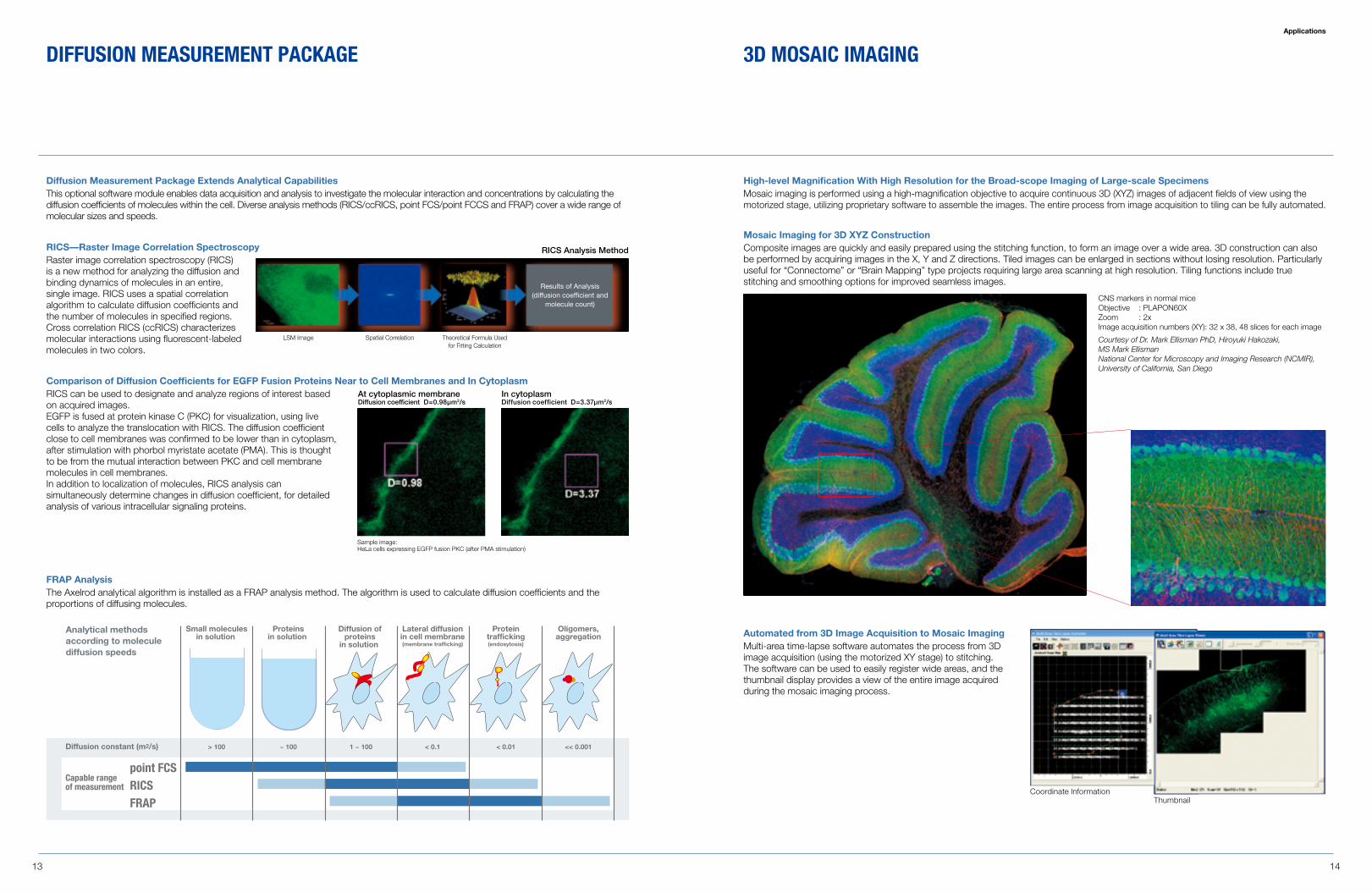
High-level Magnification With High Resolution for the Broad-scope Imaging of Large-scale SpecimensMosaic imaging is performed using a high-magnification objective to acquire continuous 3D (XYZ) images of adjacent fields of view using the motorized stage, utilizing proprietary software to assemble the images. The entire process from image acquisition to tiling can be fully automated.
Coordinate InformationThumbnail
CNS markers in normal mice Objective : PLAPON60X Zoom : 2x Image acquisition numbers (XY): 32 x 38, 48 slices for each image
Courtesy of Dr. Mark Ellisman PhD, Hiroyuki Hakozaki, MS Mark Ellisman National Center for Microscopy and Imaging Research (NCMIR), University of California, San Diego
Automated from 3D Image Acquisition to Mosaic Imaging Multi-area time-lapse software automates the process from 3D image acquisition (using the motorized XY stage) to stitching. The software can be used to easily register wide areas, and the thumbnail display provides a view of the entire image acquired during the mosaic imaging process.
Mosaic Imaging for 3D XYZ Construction Composite images are quickly and easily prepared using the stitching function, to form an image over a wide area. 3D construction can also be performed by acquiring images in the X, Y and Z directions. Tiled images can be enlarged in sections without losing resolution. Particularly useful for “Connectome” or “Brain Mapping” type projects requiring large area scanning at high resolution. Tiling functions include true stitching and smoothing options for improved seamless images.
dIFFUsIOn mEasUREmEnT PaCkagE 3d mOsaIC ImagIngApplications
RICS—Raster Image Correlation SpectroscopyRaster image correlation spectroscopy (RICS) is a new method for analyzing the diffusion and binding dynamics of molecules in an entire, single image. RICS uses a spatial correlation algorithm to calculate diffusion coefficients and the number of molecules in specified regions. Cross correlation RICS (ccRICS) characterizes molecular interactions using fluorescent-labeled molecules in two colors.
Diffusion Measurement Package Extends Analytical CapabilitiesThis optional software module enables data acquisition and analysis to investigate the molecular interaction and concentrations by calculating the diffusion coefficients of molecules within the cell. Diverse analysis methods (RICS/ccRICS, point FCS/point FCCS and FRAP) cover a wide range of molecular sizes and speeds.
RICS Analysis Method
Theoretical Formula Used for Fitting Calculation
Results of Analysis (diffusion coefficient and
molecule count)
LSM Image Spatial Correlation
At cytoplasmic membraneDiffusion coefficient D=0.98μm2/s
In cytoplasmDiffusion coefficient D=3.37μm2/s
Sample image: HeLa cells expressing EGFP fusion PKC (after PMA stimulation)
Expandability
15 16
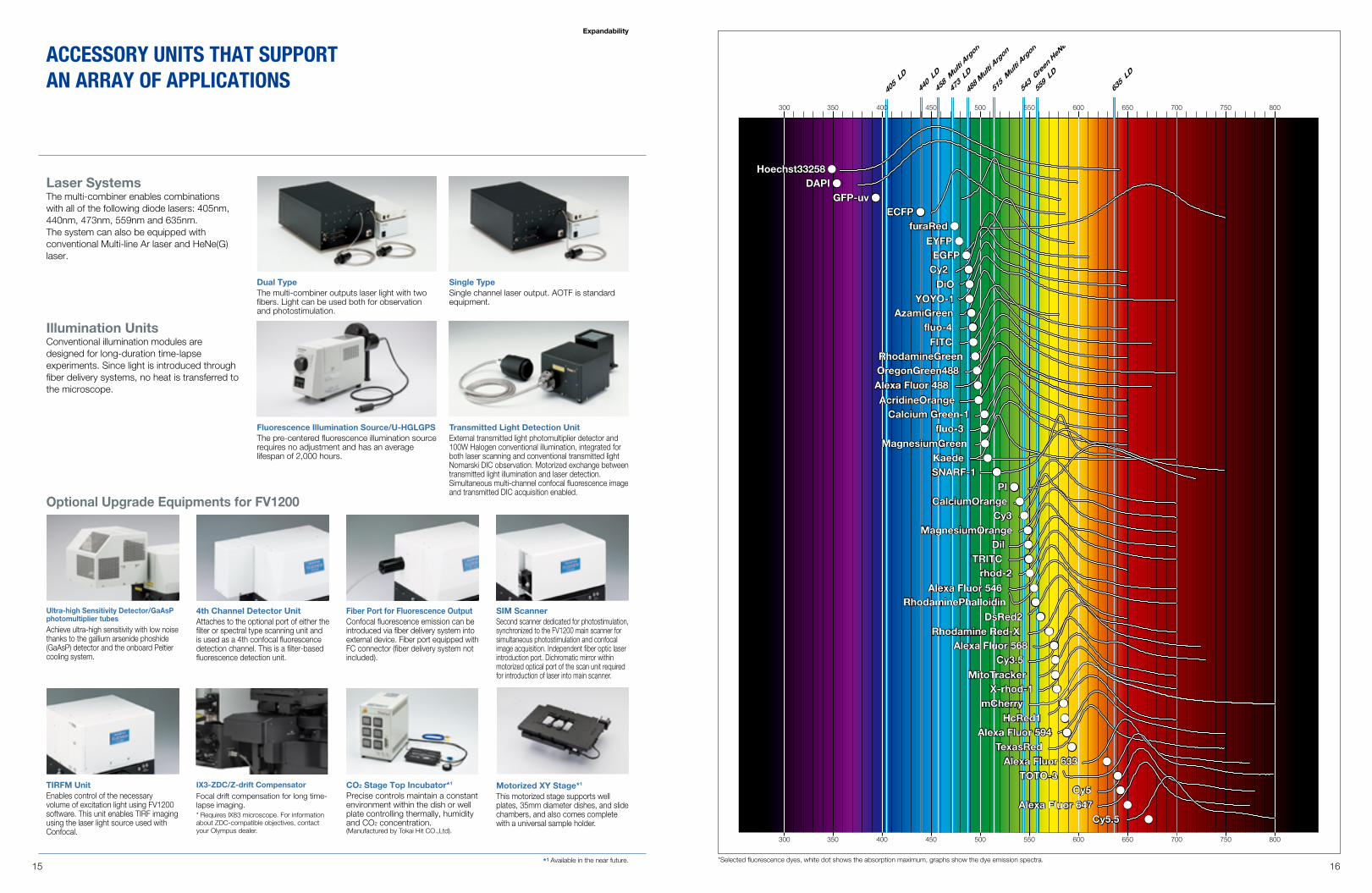
IX3-ZDC/Z-drift CompensatorFocal drift compensation for long time-lapse imaging.* Requires IX83 microscope. For information about ZDC-compatible objectives, contact your Olympus dealer.
CO2 Stage Top Incubator*1
Precise controls maintain a constant environment within the dish or well plate controlling thermally, humidity and CO2 concentration. (Manufactured by Tokai Hit CO.,Ltd).
Motorized XY Stage*1
This motorized stage supports well plates, 35mm diameter dishes, and slide chambers, and also comes complete with a universal sample holder.
Ultra-high Sensitivity Detector/GaAsP photomultiplier tubesAchieve ultra-high sensitivity with low noise thanks to the gallium arsenide phoshide (GaAsP) detector and the onboard Peltier cooling system.
Dual TypeThe multi-combiner outputs laser light with two fibers. Light can be used both for observation and photostimulation.
Fluorescence Illumination Source/U-HGLGPSThe pre-centered fluorescence illumination source requires no adjustment and has an average lifespan of 2,000 hours.
4th Channel Detector UnitAttaches to the optional port of either the filter or spectral type scanning unit and is used as a 4th confocal fluorescence detection channel. This is a filter-based fluorescence detection unit.
Laser SystemsThe multi-combiner enables combinations with all of the following diode lasers: 405nm, 440nm, 473nm, 559nm and 635nm. The system can also be equipped with conventional Multi-line Ar laser and HeNe(G) laser.
Optional Upgrade Equipments for FV1200
Single TypeSingle channel laser output. AOTF is standard equipment.
Illumination UnitsConventional illumination modules are designed for long-duration time-lapse experiments. Since light is introduced through fiber delivery systems, no heat is transferred to the microscope.
SIM ScannerSecond scanner dedicated for photostimulation, synchronized to the FV1200 main scanner for simultaneous photostimulation and confocal image acquisition. Independent fiber optic laser introduction port. Dichromatic mirror within motorized optical port of the scan unit required for introduction of laser into main scanner.
TIRFM UnitEnables control of the necessary volume of excitation light using FV1200 software. This unit enables TIRF imaging using the laser light source used with Confocal.
Fiber Port for Fluorescence OutputConfocal fluorescence emission can be introduced via fiber delivery system into external device. Fiber port equipped with FC connector (fiber delivery system not included).
aCCEssORy UnITs THaT sUPPORT an aRRay OF aPPLICaTIOns
Transmitted Light Detection UnitExternal transmitted light photomultiplier detector and 100W Halogen conventional illumination, integrated for both laser scanning and conventional transmitted light Nomarski DIC observation. Motorized exchange between transmitted light illumination and laser detection. Simultaneous multi-channel confocal fluorescence image and transmitted DIC acquisition enabled.
*Selected fluorescence dyes, white dot shows the absorption maximum, graphs show the dye emission spectra.
350300 400 450 500 550 600 650 700 750 800
350300 400 450 500 550 600 650 700 750 800
405
LD
440
LD
473
LD
635
LD
559
LD
458
Mul
ti Arg
on
515
Mul
ti Arg
on
543
Gre
en H
eNe
488
Mul
ti Arg
on
Hoechst33258 ●DAPI ●
GFP-uv ●ECFP ●
furaRed ●EYFP ●
EGFP ●Cy2 ●
DiO ●YOYO-1 ●
AzamiGreen ●fluo-4 ●
FITC ●RhodamineGreen ●OregonGreen488 ●Alexa Fluor 488 ●AcridineOrange ●
Calcium Green-1 ●fluo-3 ●
MagnesiumGreen ●Kaede ●SNARF-1 ●
PI ●CalciumOrange ●
Cy3 ●MagnesiumOrange ●
Dil ●TRITC ●
rhod-2 ●Alexa Fluor 546 ●
RhodaminePhalloidin ●DsRed2 ●
Rhodamine Red-X ●Alexa Fluor 568 ●
Cy3.5 ●MitoTracker ●
X-rhod-1 ●mCherry ●
HcRed1 ●Alexa Fluor 594 ●
TexasRed ●Alexa Fluor 633 ●
TOTO-3 ●Cy5 ●
Alexa Fluor 647 ●Cy5.5 ●
*1 Available in the near future.
17 18
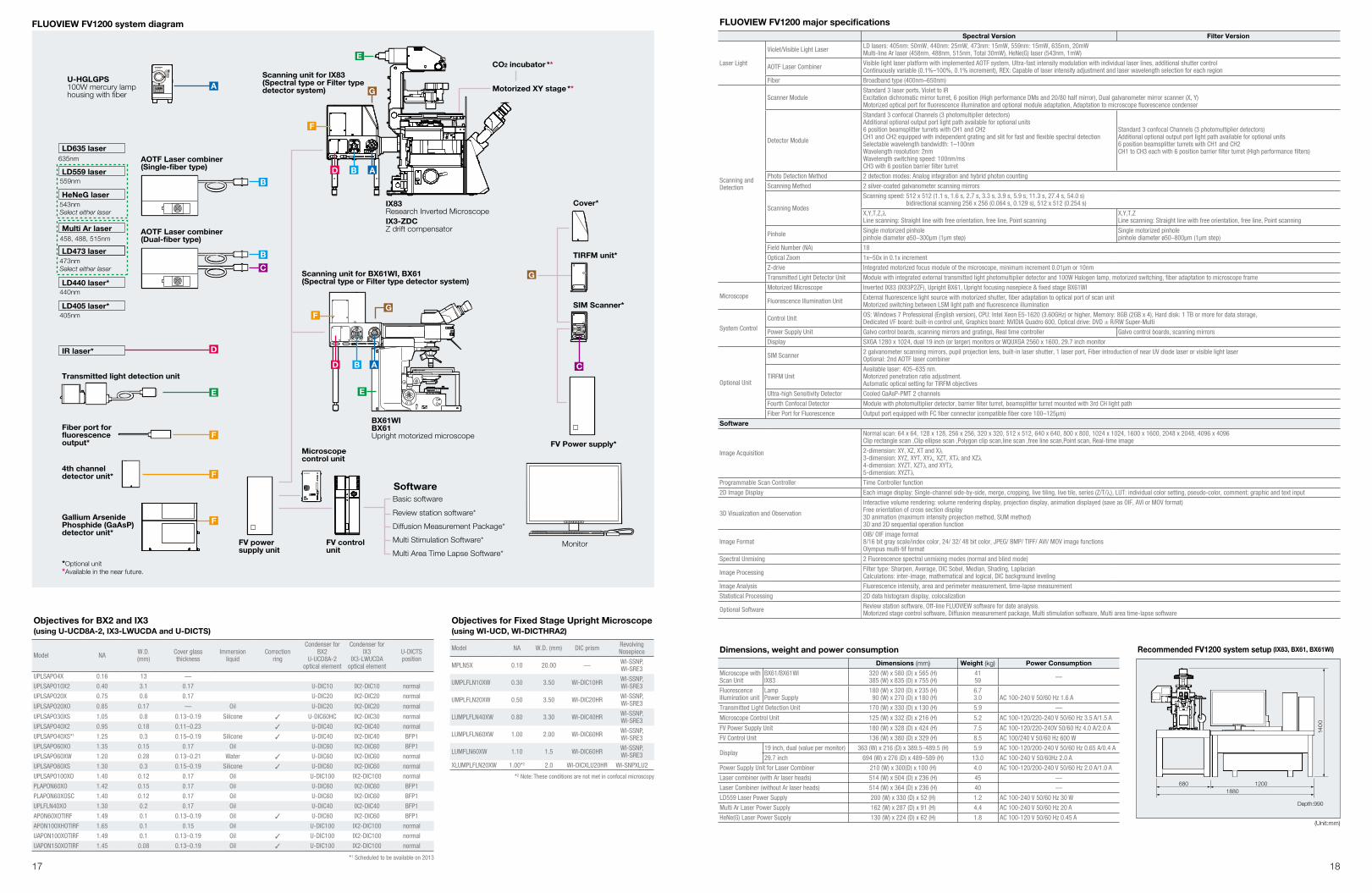
IX83Research Inverted MicroscopeIX3-ZDCZ drift compensator
BX61WIBX61Upright motorized microscope
543nmSelect either laser
473nm
440nm
Select either laser
559nm
458, 488, 515nm
405nm
A
B
D
E
F
F
F
E
FG
D B
E
A
F
G
ABD
G
C
LD635 laserAOTF Laser combiner(Single-fiber type)
Scanning unit for IX83(Spectral type or Filter type detector system)
Scanning unit for BX61WI, BX61(Spectral type or Filter type detector system)
CO2 incubator **
Motorized XY stage **
Cover*
TIRFM unit*
Microscope control unit
FV control unit
FV power supply unit
SIM Scanner*
FV Power supply*
Monitor
SoftwareBasic software
Review station software*
Diffusion Measurement Package*
Multi Stimulation Software*
Multi Area Time Lapse Software*
AOTF Laser combiner(Dual-fiber type)
LD559 laser
HeNeG laser
Multi Ar laser
LD473 laser
LD440 laser*
LD405 laser*
IR laser*
Transmitted light detection unit
Fiber port for fluorescence output*
4th channel detector unit*
Gallium Arsenide Phosphide (GaAsP) detector unit*
*Optional unit*Available in the near future.
635nm
U-HGLGPS100W mercury lamp housing with fiber
B
C
FLUOVIEW FV1200 system diagram FLUOVIEW FV1200 major specificationsSpectral Version Filter Version
Laser Light
Violet/Visible Light Laser LD lasers: 405nm: 50mW, 440nm: 25mW, 473nm: 15mW, 559nm: 15mW, 635nm, 20mW Multi-line Ar laser (458nm, 488nm, 515nm, Total 30mW), HeNe(G) laser (543nm, 1mW)
AOTF Laser Combiner Visible light laser platform with implemented AOTF system, Ultra-fast intensity modulation with individual laser lines, additional shutter control Continuously variable (0.1%–100%, 0.1% increment), REX: Capable of laser intensity adjustment and laser wavelength selection for each region
Fiber Broadband type (400nm–650nm)
Scanning and Detection
Scanner ModuleStandard 3 laser ports, Violet to IR Excitation dichromatic mirror turret, 6 position (High performance DMs and 20/80 half mirror), Dual galvanometer mirror scanner (X, Y) Motorized optical port for fluorescence illumination and optional module adaptation, Adaptation to microscope fluorescence condenser
Detector Module
Standard 3 confocal Channels (3 photomultiplier detectors) Additional optional output port light path available for optional units 6 position beamsplitter turrets with CH1 and CH2 CH1 and CH2 equipped with independent grating and slit for fast and flexible spectral detection Selectable wavelength bandwidth: 1–100nm Wavelength resolution: 2nm Wavelength switching speed: 100nm/ms CH3 with 6 position barrier filter turret
Standard 3 confocal Channels (3 photomultiplier detectors) Additional optional output port light path available for optional units 6 position beamsplitter turrets with CH1 and CH2 CH1 to CH3 each with 6 position barrier filter turret (High performance filters)
Photo Detection Method 2 detection modes: Analog integration and hybrid photon counting
Scanning Method 2 silver-coated galvanometer scanning mirrors
Scanning Modes
Scanning speed: 512 x 512 (1.1 s, 1.6 s, 2.7 s, 3.3 s, 3.9 s, 5.9 s, 11.3 s, 27.4 s, 54.0 s) bidirectional scanning 256 x 256 (0.064 s, 0.129 s), 512 x 512 (0.254 s)
X,Y,T,Z,λ Line scanning: Straight line with free orientation, free line, Point scanning
X,Y,T,Z Line scanning: Straight line with free orientation, free line, Point scanning
Pinhole Single motorized pinhole pinhole diameter ø50–300µm (1µm step)
Single motorized pinhole pinhole diameter ø50–800µm (1µm step)
Field Number (NA) 18
Optical Zoom 1x–50x in 0.1x increment
Z-drive Integrated motorized focus module of the microscope, minimum increment 0.01µm or 10nm
Transmitted Light Detector Unit Module with integrated external transmitted light photomultiplier detector and 100W Halogen lamp, motorized switching, fiber adaptation to microscope frame
MicroscopeMotorized Microscope Inverted IX83 (IX83P2ZF), Upright BX61, Upright focusing nosepiece & fixed stage BX61WI
Fluorescence Illumination Unit External fluorescence light source with motorized shutter, fiber adaptation to optical port of scan unit Motorized switching between LSM light path and fluorescence illumination
System Control
Control Unit OS: Windows 7 Professional (English version), CPU: Intel Xeon E5-1620 (3.60GHz) or higher, Memory: 8GB (2GB x 4), Hard disk: 1 TB or more for data storage, Dedicated I/F board: built-in control unit, Graphics board: NVIDIA Quadro 600, Optical drive: DVD ± R/RW Super-Multi
Power Supply Unit Galvo control boards, scanning mirrors and gratings, Real time controller Galvo control boards, scanning mirrors
Display SXGA 1280 x 1024, dual 19 inch (or larger) monitors or WQUXGA 2560 x 1600, 29.7 inch monitor
Optional Unit
SIM Scanner 2 galvanometer scanning mirrors, pupil projection lens, built-in laser shutter, 1 laser port, Fiber introduction of near UV diode laser or visible light laser Optional: 2nd AOTF laser combiner
TIRFM UnitAvailable laser: 405–635 nm. Motorized penetration ratio adjustment. Automatic optical setting for TIRFM objectives
Ultra-high Sensitivity Detector Cooled GaAsP-PMT 2 channels
Fourth Confocal Detector Module with photomultiplier detector, barrier filter turret, beamsplitter turret mounted with 3rd CH light path
Fiber Port for Fluorescence Output port equipped with FC fiber connector (compatible fiber core 100–125µm)
Software
Image Acquisition
Normal scan: 64 x 64, 128 x 128, 256 x 256, 320 x 320, 512 x 512, 640 x 640, 800 x 800, 1024 x 1024, 1600 x 1600, 2048 x 2048, 4096 x 4096Clip rectangle scan ,Clip ellipse scan ,Polygon clip scan,line scan ,free line scan,Point scan, Real-time image
2-dimension: XY, XZ, XT and Xλ 3-dimension: XYZ, XYT, XYλ, XZT, XTλ and XZλ 4-dimension: XYZT, XZTλ and XYTλ 5-dimension: XYZTλ
Programmable Scan Controller Time Controller function
2D Image Display Each image display: Single-channel side-by-side, merge, cropping, live tiling, live tile, series (Z/T/λ), LUT: individual color setting, pseudo-color, comment: graphic and text input
3D Visualization and Observation
Interactive volume rendering: volume rendering display, projection display, animation displayed (save as OIF, AVI or MOV format) Free orientation of cross section display 3D animation (maximum intensity projection method, SUM method) 3D and 2D sequential operation function
Image Format OIB/ OIF image format 8/16 bit gray scale/index color, 24/ 32/ 48 bit color, JPEG/ BMP/ TIFF/ AVI/ MOV image functions Olympus multi-tif format
Spectral Unmixing 2 Fluorescence spectral unmixing modes (normal and blind mode)
Image Processing Filter type: Sharpen, Average, DIC Sobel, Median, Shading, Laplacian Calculations: inter-image, mathematical and logical, DIC background leveling
Image Analysis Fluorescence intensity, area and perimeter measurement, time-lapse measurement
Statistical Processing 2D data histogram display, colocalization
Optional Software Review station software, Off-line FLUOVIEW software for date analysis. Motorized stage control software, Diffusion measurement package, Multi stimulation software, Multi area time-lapse software
Dimensions, weight and power consumption
Dimensions (mm) Weight (kg) Power ConsumptionMicroscope with Scan Unit
BX61/BX61WI IX83
320 (W) x 580 (D) x 565 (H) 385 (W) x 835 (D) x 755 (H)
41 59 —
Fluorescence Illumination unit
Lamp Power Supply
180 (W) x 320 (D) x 235 (H) 90 (W) x 270 (D) x 180 (H)
6.7 3.0
AC 100-240 V 50/60 Hz 1.6 A
Transmitted Light Detection Unit 170 (W) x 330 (D) x 130 (H) 5.9 —
Microscope Control Unit 125 (W) x 332 (D) x 216 (H) 5.2 AC 100-120/220-240 V 50/60 Hz 3.5 A/1.5 A
FV Power Supply Unit 180 (W) x 328 (D) x 424 (H) 7.5 AC 100-120/220-240V 50/60 Hz 4.0 A/2.0 A
FV Control Unit 136 (W) x 380 (D) x 329 (H) 8.5 AC 100/240 V 50/60 Hz 600 W
Display19 inch, dual (value per monitor) 363 (W) x 216 (D) x 389.5–489.5 (H) 5.9 AC 100-120/200-240 V 50/60 Hz 0.65 A/0.4 A
29.7 inch 694 (W) x 276 (D) x 489–589 (H) 13.0 AC 100-240 V 50/60Hz 2.0 A
Power Supply Unit for Laser Combiner 210 (W) x 300(D) x 100 (H) 4.0 AC 100-120/200-240 V 50/60 Hz 2.0 A/1.0 A
Laser combiner (with Ar laser heads) 514 (W) x 504 (D) x 236 (H) 45 —
Laser Combiner (without Ar laser heads) 514 (W) x 364 (D) x 236 (H) 40 —
LD559 Laser Power Supply 200 (W) x 330 (D) x 52 (H) 1.2 AC 100-240 V 50/60 Hz 30 W
Multi Ar Laser Power Supply 162 (W) x 287 (D) x 91 (H) 4.4 AC 100-240 V 50/60 Hz 20 A
HeNe(G) Laser Power Supply 130 (W) x 224 (D) x 62 (H) 1.8 AC 100-120 V 50/60 Hz 0.45 A
Objectives for BX2 and IX3 (using U-UCD8A-2, IX3-LWUCDA and U-DICTS)
Model NA W.D. (mm)
Cover glass thickness
Immersion liquid
Correction ring
Condenser for BX2
U-UCD8A-2 optical element
Condenser for IX3
IX3-LWUCDA optical element
U-DICTS position
UPLSAPO4X 0.16 13 —
UPLSAPO10X2 0.40 3.1 0.17 U-DIC10 IX2-DIC10 normal
UPLSAPO20X 0.75 0.6 0.17 U-DIC20 IX2-DIC20 normal
UPLSAPO20XO 0.85 0.17 — Oil U-DIC20 IX2-DIC20 normal
UPLSAPO30XS 1.05 0.8 0.13–0.19 Silicone 3 U-DIC60HC IX2-DIC30 normal
UPLSAPO40X2 0.95 0.18 0.11–0.23 3 U-DIC40 IX2-DIC40 normal
UPLSAPO40XS*1 1.25 0.3 0.15–0.19 Silicone 3 U-DIC40 IX2-DIC40 BFP1
UPLSAPO60XO 1.35 0.15 0.17 Oil U-DIC60 IX2-DIC60 BFP1
UPLSAPO60XW 1.20 0.28 0.13–0.21 Water 3 U-DIC60 IX2-DIC60 normal
UPLSAPO60XS 1.30 0.3 0.15–0.19 Silicone 3 U-DIC60 IX2-DIC60 normal
UPLSAPO100XO 1.40 0.12 0.17 Oil U-DIC100 IX2-DIC100 normal
PLAPON60XO 1.42 0.15 0.17 Oil U-DIC60 IX2-DIC60 BFP1
PLAPON60XOSC 1.40 0.12 0.17 Oil U-DIC60 IX2-DIC60 BFP1
UPLFLN40XO 1.30 0.2 0.17 Oil U-DIC40 IX2-DIC40 BFP1
APON60XOTIRF 1.49 0.1 0.13–0.19 Oil 3 U-DIC60 IX2-DIC60 BFP1
APON100XHOTIRF 1.65 0.1 0.15 Oil U-DIC100 IX2-DIC100 normal
UAPON100XOTIRF 1.49 0.1 0.13–0.19 Oil 3 U-DIC100 IX2-DIC100 normal
UAPON150XOTIRF 1.45 0.08 0.13–0.19 Oil 3 U-DIC100 IX2-DIC100 normal
Objectives for Fixed Stage Upright Microscope (using WI-UCD, WI-DICTHRA2)
Model NA W.D. (mm) DIC prism Revolving Nosepiece
MPLN5X 0.10 20.00 — WI-SSNP,WI-SRE3
UMPLFLN10XW 0.30 3.50 WI-DIC10HR WI-SSNP,WI-SRE3
UMPLFLN20XW 0.50 3.50 WI-DIC20HR WI-SSNP,WI-SRE3
LUMPLFLN40XW 0.80 3.30 WI-DIC40HR WI-SSNP,WI-SRE3
LUMPLFLN60XW 1.00 2.00 WI-DIC60HR WI-SSNP,WI-SRE3
LUMFLN60XW 1.10 1.5 WI-DIC60HR WI-SSNP,WI-SRE3
XLUMPLFLN20XW 1.00*2 2.0 WI-DICXLU20HR WI-SNPXLU2
Recommended FV1200 system setup (IX83, BX61, BX61WI)
(Unit:mm)
140
0
Depth:990
12001880
680*2 Note: These conditions are not met in confocal microscopy
*1 Scheduled to be available on 2013