vortex generator installation addendum 1 introductionzlinaero.com/allegati/note/14/vortex generator...
TRANSCRIPT
Vortex GeneratorInstallation Addendum
Vortex Generator Installation Addendum
1 Introduction The Zlin Aviation, s.r.o. Vortex Generator Kit, when installed in accordance with
these instructions and other applicable data, results in better handling, a lower stall speed, and more controllable flare during landing. It is important to follow the directions carefully and ensure all measurements are accurate before finally affixing the Vortex Generators. Failure to install the Vortex Generators within the specifications of this Addendum may result in extreme and unpredictable changes in flight characteristics. 2 Level of Certification Required
This modification requires either LSA Repairman Maintenance certification or an A&P certification. This maintenance is considered Line Maintenance.3 Parts Listing and Tools Required
3.1 Parts Included with Vortex Generator KitDescription QtyZlin Aviation Vortex Generators 46Epoxy Glue 1
3.2 Parts Not Included with Vortex Generator KitNone.
3.3 Tools Required• Tape Measure• Masking Tape• Dry Erase Marker• Rubbing Alcohol
4 Mapping Vortex Generator Locations along the Wings
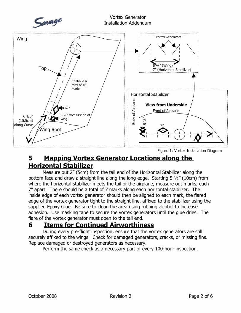
Along the curve from the front edge of the wing heading towards the tail on the upward facing side of the wing, measure out 6 1/8” (15.5cm), and draw a straight line along the long edge of the wing. Starting 5 ¼” (13.33cm) from the first rib of the wing, measure out marks, each 8 ¾” apart. There should be a total of 16 marks along each wing. The inside edge of the vortex generator, with the narrow front edge of the generator tight to the horizontal line, should then be affixed to wing at each of those marked points using the supplied Epoxy Glue. Be sure to clean the area with rubbing alcohol to increase adhesion. Use masking tape to securely hold down the generators until the glue dries. The flare of the vortex generator must open to the tail end. See Figure 1.
October 2008 Revision 2 Page 1 of 6
Vortex GeneratorInstallation Addendum
5 Mapping Vortex Generator Locations along the Horizontal Stabilizer
Measure out 2” (5cm) from the tail end of the Horizontal Stabilizer along the bottom face and draw a straight line along the long edge. Starting 5 ½” (10cm) from where the horizontal stabilizer meets the tail of the airplane, measure out marks, each 7” apart. There should be a total of 7 marks along each horizontal stabilizer. The inside edge of each vortex generator should then be aligned to each mark, the flared edge of the vortex generator tight to the straight line, affixed to the stabilizer using the supplied Epoxy Glue. Be sure to clean the area using rubbing alcohol to increase adhesion. Use masking tape to secure the vortex generators until the glue dries. The flare of the vortex generator must open to the tail end.6 Items for Continued Airworthiness
During every pre-flight inspection, ensure that the vortex generators are still securely affixed to the wings. Check for damaged generators, cracks, or missing fins. Replace damaged or destroyed generators as necessary.
Perform the same check as a necessary part of every 100-hour inspection.
October 2008 Revision 2 Page 2 of 6
Body
of
Airp
lane
Front of Airplane
View from Underside
2”
5 ½
”
7”
6 1/8” (15.5cm)
Along Curve
8 ¾”
5 ¼“ from first rib of wing
Continue a total of 16 marks
8 ¾” (Wing)7” (Horizontal Stabilizer)
Vortex Generators
Horizontal Stabilizer
Wing
Top
Figure 1: Vortex Installation Diagram
Wing Root

Vortex GeneratorInstallation Addendum
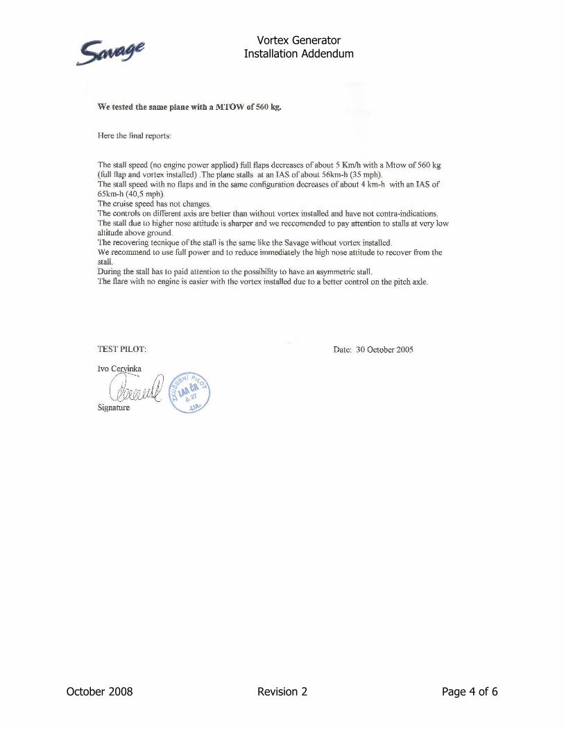
7 Changes in Flight Characteristics
7.1 Zlin Aviation, s.r.o. Test Flight Results
October 2008 Revision 2 Page 3 of 6
Vortex GeneratorInstallation Addendum
October 2008 Revision 2 Page 4 of 6
Vortex GeneratorInstallation Addendum
8 Revisions to Flight Manual Upon installation, the Flight Manual will be revised to include the following
changes:1. Section 9.3.1 Pre-Flight Checklist
• Tables 5 Left Wing and 7 Right Wing will have one row added to each that states: ” Ensure that the vortex generators are still securely affixed to the wings and horizontal stabilizer.“
2. Addition of Annex 1: Vortex Generator StatementAt the end of the manual, an Annex will be added, titled “Vortex Generator Statement.” This Annex will read: “With the installation of Vortex Generators, expect the following changes to the aircraft’s flight characteristics:• The stall speed decreases about 3 mph (2.5 kts) with an MTOW of
1235 lbs.• The stall speed with no flaps and in the same configuration decreases
about 2.5 mph (2 kts) with an IAS of 40.5 mph (35 kts).• The cruise speed does not change.• The controls on the different axes are better than without Vortex
Generators installed and have no contra-indications.• The stall due to higher nose attitude is sharper and it is recommended
that care be taken with stalls at a low altitude above the ground.• There is no change to the stall recovery method with Vortex
Generators installed.• Section 4.3.1 Specification Table
The table will have an annotation added to it, indicating that for aircraft equipped with Vortex Generators, to refer to Annex 1.
3. Section 6.4 Equipment ListThe list will include the following information:• Description: Vortex Generators• Manufacturer: Zlin Aviation, s.r.o.• Model: VORTEX
The manual will be given a proper remark in Section 2, Amendment Record Sheet.9 Revisions to Maintenance Manual
Upon installation, the Maintenance Manual will be revised to include the following changes:
1. Section 11.4.2 FuselageThe section will include an additional paragraph stating: “Ensure that the vortex generators are still securely affixed to the wings and horizontal stabilizer. Check for damaged generators, cracks, or missing fins. Replace damaged or destroyed generators as necessary.”
The manual will be given a proper remark in Section 2, Amendment Record Sheet.
October 2008 Revision 2 Page 5 of 6
Vortex GeneratorInstallation Addendum
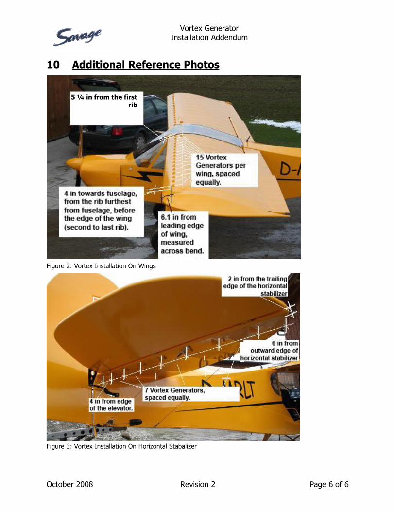
10 Additional Reference Photos
October 2008 Revision 2 Page 6 of 6
Figure 2: Vortex Installation On Wings
Figure 3: Vortex Installation On Horizontal Stabalizer
5 ¼ in from the first rib