volumetric 3-component velocity measurements of vortex...
TRANSCRIPT

14th Int Symp on Applications of Laser Techniques to Fluid Mechanics Lisbon, Portugal, 07-10 July, 2008
- 1 -
Volumetric 3-Component Velocity Measurements of Vortex Rings from Inclined
Exits
Daniel R. Troolin1, Ellen K. Longmire2,
1: Fluid Mechanics Division, TSI Incorporated, St. Paul, USA, [email protected]
2: Dept. of Aerospace Engineering & Mechanics, University of Minnesota, Minneapolis, USA, [email protected] Abstract Vortex rings were generated by driving pistons within circular cylinders of inner diameter D = 72.8 mm at a constant velocity U0 over a distance L = D. The Reynolds number, U0L/(2ν), was 2500. The flow downstream of circular and inclined exits was examined using volumetric 3-component velocimetry (V3V). The circular exit yields a standard primary vortex ring that propagates downstream at a constant velocity, and a lingering trailing ring of opposite sign associated with the stopping of the piston. By contrast, the inclined nozzle yields a much more complicated structure. A tilted primary vortex ring develops and interacts with two trailing rings that initially have circulation of opposite sign. The first trailing ring begins forming at the upstream lip of the cylinder exit. After the primary ring has completely detached from the nozzle, a second trailing ring forms starting from the downstream nozzle lip. The trailing vortices intertwine and are stretched and drawn through the center of the primary ring. This behavior was observed for multiple inclination angles. Increased inclination was associated with stronger interactions between the primary and trailing vortices as well as earlier breakdown.
1. Introduction
Vortex rings generated by impulses occur in many environmental, biological, and industrial applications. The flow associated with vortex rings generated from axisymmetric boundary conditions has been studied extensively (see the reviews by Shariff and Leonard, 1987, and Lim and Nickels, 1995, for example). In many applications however, the boundary conditions are not axisymmetric, and therefore the effects of asymmetry on the resulting vortex development, propagation, and breakdown are of interest. In the current study, we examine the effect of inclined trailing edge geometry on vortex ring development. Vortex rings initiated downstream of cylinders with inclined exits were first examined by Webster and Longmire (1998) using planar particle image velocimetry (PIV). The authors viewed instantaneous slices of flow in different azimuthal planes to reconstruct a picture of the overall flow behavior. The reconstruction revealed a highly complex vortex structure including a primary ring and additional vortex tubes that initially extended upstream into the cylinder and subsequently passed through the primary ring. The strength of the additional tubes increased with increasing trailing edge angle. Also, the overall propagation speed and penetration distance of the primary vortex decreased with increasing trailing edge angle. In a flow visualization study on rings initiated from similar cylinders, Lim (1998) noted the presence of circumferential flow within the primary ring cores. In the present work, we employ a volumetric 3-component velocimetry (V3V) system to examine the evolving three-dimensional flow structure directly. As will be shown below, this technique confirms some of the behavior postulated by Webster and Longmire, but also reveals new dynamics of the flow that were previously not known or understood. 2. Facility
The experiments were conducted in a water-filled glass tank of square cross section with 600 mm sides and 600 mm depth. Vortex rings were generated by displacing a piston through

14th Int Symp on Applications of Laser Techniques to Fluid Mechanics Lisbon, Portugal, 07-10 July, 2008
- 2 -
submerged cylinders with flat and inclined exits. The inner diameter (D) of the cylinders was 72.8 mm with wall thickness of 1.7 mm. The inclined exits were cut so that the axial distances between the longest and shortest lip locations were D/4 (14°) and D/2 (26°). The piston, which was axisymmetric, was actuated to travel at nearly constant velocity of 66.2 mm/s for a distance L = D before stopping abruptly at a final location D upstream of the average cylinder lip location. The vortex generating apparatus is described in detail in Webster and Longmire (1998). The plots shown are normalized by the cylinder diameter, and the time increment is consistent with that used by Webster and Longmire, where t* = (t – t0)U0/L, t0 is the time when the piston begins moving, L is the stroke length, and U0 is the constant piston velocity. Also, in keeping with the conventions of Webster and Longmire, the angle ψ is defined to be zero at the location where the cylinder lip was longest, and ψ = π where it was shortest, and the flow Reynolds number is defined as Г0/ν where Г0 = U0L/2. In the current experiments, the Reynolds number was held fixed at 2500 which is slightly lower than the value of 2800 associated with Webster and Longmire's PIV measurements. 2. Experimental Setup
The volumetric 3-component velocimetry (V3V) technique described by Pereira et al. (2000) was used to measure the volumetric velocity fields. The flow was illuminated by a dual-head Nd:YAG laser with 200 mJ/pulse. Two -25 mm cylindrical lenses were mounted in front of the beam exit in perpendicular orientations to produce an ellipsoidal cone of laser light. A mirror reflected the light by 90° into the water tank, and another mirror on the opposite side of the tank was used to reflect light back toward the measurement region to increase the illumination intensity. Polycrystalline particles of diameter 100 μm were used as the tracers.
The volumetric camera consisted of three apertures arranged in an equilateral triangle of side length 170 mm, each containing a CCD array with 4 million pixels (2048 × 2048) of size 7.4 microns and depth 12 bits. Three 50 mm camera lenses were used with aperture settings of f#16. The camera was mounted an optical distance of 701 mm from the back plane of the measurement region at 90° to the illuminating light.
The V3V camera frames and laser pulses were triggered by a TSI 610035 synchronizer with 1 ns resolution. Figure 1 is a schematic representation of camera and laser synchronization, in which the pulses from each laser (green line) were timed to straddle neighboring camera frames (red line) in order to produce images suitable for 3D particle tracking, in a way similar to that used in particle image velocimetry (PIV). The time between frame-straddled laser pulses (∆t) was 3500 μs. The synchronizer (blue line) was externally triggered (orange line) to coincide with the initiation of the piston stroke. The volumetric velocity fields were captured at 7.25 Hz. The images were streamed to a HYPER2 HyperStreaming computer, and subsequently analyzed.
Instantaneous velocity fields were determined in four steps: identification of 2D particle locations from each of three apertures, determination of 3D particle locations in space, tracking individual particles in the volume, and interpolating the resulting randomly-spaced vectors onto a Cartesian grid.
Fig. 1 Timing diagram for V3V captures.

14th Int Symp on Applications of Laser Techniques to Fluid Mechanics Lisbon, Portugal, 07-10 July, 2008
- 3 -
2D Particle Identification. A single V3V capture consists of 6 separate images: three images each from frame A and frame B. The locations of tracer particles in each image are determined by setting a baseline intensity threshold such that any valid particle must have a peak intensity above this threshold, and a local ratio in which the particle peak intensity must be larger than the local background by this ratio. A Gaussian intensity profile is fitted to the particle image, and the peak represents the center of the particle. 3D Particle Identification. A single particle, when viewed from three spatial locations, appears as a triangle, or “triplet,” when the images are effectively combined through a spatial calibration. The centroid of the triplet represents the x and y location, and the size of the triangle represents the z location (Fig. 2).
The correspondence of a 2D particle in one image to the same particle in the other two images is achieved through a volumetric spatial calibration. The spatial calibration is determined by traversing a single-plane target through the measurement region, and capturing images at regular intervals. Dots on the calibration target are spaced regularly at 5 mm in the horizontal and vertical directions, and the target is traversed by 5 mm increments in the depth direction. The calibration dot locations from each image are combined to define a signature graph, in which a defining triangle size is determined for each plane.
Consider a 2D particle as seen by the top image. A single dot in the top aperture defines a ray in the left and right apertures. The 3D location algorithm searches along this defining ray in the left and right images simulaneously for possible 2D particle matches. If a triplet is not found that falls within 0.5 pixels of the triangle defined by the signature graph, the 2D particles are not used. This process is repeated for all particles in the field. 3D Particle Tracking. The 3D particle tracking algorithm is a relaxation method based upon the work of Ohmi and Lee (2000) and Pereira et. al (2006). Once the volumetric particle locations are determined in frame A and frame B, the particles are divided into subgroups called “clusters” according to their spatial locations. Clusters here can be thought of as similar to interrogation regions in PIV. Clusters in B are larger in volume than corresponding clusters in A because particles may move out of the initial cluster area. Within a cluster, each pair of corresponding particles is assigned a number representing match probabilities. For example, P(m,n) is the match probability between particle m in frame A and particle n in frame B. Initially each particle pair has the same probability, 1/N, where N is the number of possible pairs between A and B for each cluster. The probability computation is based on the assumption that neighboring particles move similarly. These probabilities are then iteratively recomputed for all particles in the cluster, until they converge. For particle m in frame A, the maximum match probability P(m,n) is found among P(m,1), P(m,2),... If it is greater than a specified threshold, then (m,n) is a matched pair. Grid Interpolation. After the 3D particle tracking step, the vectors are randomly spaced according to particle locations. In order to compute quantities such as vorticity and swirl, it is useful to have vectors on a Cartesian grid. These vectors were found through regular Gaussian-weighted interpolation.
In the experiments described, the resulting measurement volume was a cube approximately 140 mm on a side. A typical single capture yielded between 30,000 and 40,000 independent randomly-spaced velocity vectors. The vectors were then interpolated onto a rectangular grid with 4 mm vector spacing, which resulted in approximately 43,000 vectors.
Fig. 2 V3V triplets.

14th Int Symp on Applications of Laser Techniques to Fluid Mechanics Lisbon, Portugal, 07-10 July, 2008
- 4 -
3. Results
Velocity data generated from the standard cylinder with flat exit reveal an axisymmetric primary ring with diameter of 1.25D that propagates downstream at constant speed, corresponding closely with the previous PIV results of Webster and Longmire (1998) at similar Reynolds number. Plots of vorticity magnitude isosurfaces are shown in Fig. 3 for flow downstream of the standard cylinder with flat exit at a relatively early time, t* = 2.13. Note that all data plots are presented in Cartesian coordinates with -y aligned in the streamwise direction. The plot on the left shows an off-axis perspective view of the vortex ring with the cylinder depicted in gray. The plot on the right is a view from beneath the ring, looking up toward the cylinder exit. The larger primary ring results from the sudden impulse of the piston that forces a slug of fluid through and out of the
cylinder. A boundary layer forms on the inside wall of the cylinder and as the slug of fluid separates from the nozzle lip, a cylindrical sheet of vorticity rolls up into a continuous ring. At this time, the primary ring is located approximately 0.4D downstream of the cylinder exit. The rotation of this ring is such that fluid is drawn downward through the center of ring. Upstream of the primary ring, a weaker trailing vortex is observed near the lip of the cylinder exit. The trailing vortex, which has rotation opposite that of the primary ring, is caused by the sudden termination of the piston motion. A schematic of this case is given in Fig. 4, with the primary ring in red and the trailing ring in blue. Arrows indicate the direction of rotation of each ring.
The case of a vortex ring generated from a nozzle with a flat exit has been studied extensively in the literature (e.g. Shariff & Leonard,1992, Lim & Nickels, 1995, Gharib et al., 1998, Krueger, 2005). The evolution of the two rings is fairly well understood, though typically, little focus is placed on the characteristics of the trailing ring.
Fig. 4 Schematic of primary and trailing vortices emitted from the standard cylinder.
Fig. 3 Vorticity magnitude isosurfaces for the standard cylinder at t* = 2.13. The normalized isosurfaces are at values of ωD/U0 = 4.4 (orange) and 6.1 (red).
14th Int Symp on Applications of Laser Techniques to Fluid Mechanics Lisbon, Portugal, 07-10 July, 2008
- 5 -
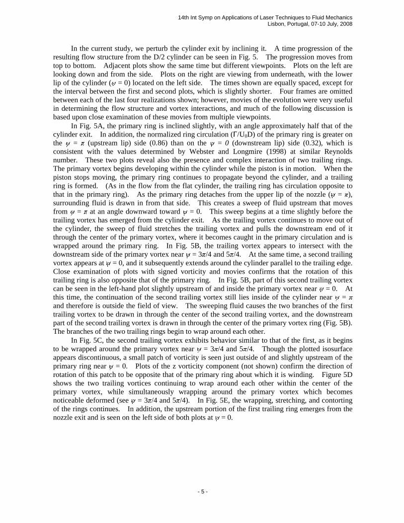
In the current study, we perturb the cylinder exit by inclining it. A time progression of the resulting flow structure from the D/2 cylinder can be seen in Fig. 5. The progression moves from top to bottom. Adjacent plots show the same time but different viewpoints. Plots on the left are looking down and from the side. Plots on the right are viewing from underneath, with the lower lip of the cylinder (ψ = 0) located on the left side. The times shown are equally spaced, except for the interval between the first and second plots, which is slightly shorter. Four frames are omitted between each of the last four realizations shown; however, movies of the evolution were very useful in determining the flow structure and vortex interactions, and much of the following discussion is based upon close examination of these movies from multiple viewpoints.
In Fig. 5A, the primary ring is inclined slightly, with an angle approximately half that of the cylinder exit. In addition, the normalized ring circulation (Г/U0D) of the primary ring is greater on the ψ = π (upstream lip) side (0.86) than on the ψ = 0 (downstream lip) side (0.32), which is consistent with the values determined by Webster and Longmire (1998) at similar Reynolds number. These two plots reveal also the presence and complex interaction of two trailing rings. The primary vortex begins developing within the cylinder while the piston is in motion. When the piston stops moving, the primary ring continues to propagate beyond the cylinder, and a trailing ring is formed. (As in the flow from the flat cylinder, the trailing ring has circulation opposite to that in the primary ring). As the primary ring detaches from the upper lip of the nozzle (ψ = π), surrounding fluid is drawn in from that side. This creates a sweep of fluid upstream that moves from ψ = π at an angle downward toward ψ = 0. This sweep begins at a time slightly before the trailing vortex has emerged from the cylinder exit. As the trailing vortex continues to move out of the cylinder, the sweep of fluid stretches the trailing vortex and pulls the downstream end of it through the center of the primary vortex, where it becomes caught in the primary circulation and is wrapped around the primary ring. In Fig. 5B, the trailing vortex appears to intersect with the downstream side of the primary vortex near ψ = 3π/4 and 5π/4. At the same time, a second trailing vortex appears at ψ = 0, and it subsequently extends around the cylinder parallel to the trailing edge. Close examination of plots with signed vorticity and movies confirms that the rotation of this trailing ring is also opposite that of the primary ring. In Fig. 5B, part of this second trailing vortex can be seen in the left-hand plot slightly upstream of and inside the primary vortex near ψ = 0. At this time, the continuation of the second trailing vortex still lies inside of the cylinder near ψ = π and therefore is outside the field of view. The sweeping fluid causes the two branches of the first trailing vortex to be drawn in through the center of the second trailing vortex, and the downstream part of the second trailing vortex is drawn in through the center of the primary vortex ring (Fig. 5B). The branches of the two trailing rings begin to wrap around each other.
In Fig. 5C, the second trailing vortex exhibits behavior similar to that of the first, as it begins to be wrapped around the primary vortex near ψ = 3π/4 and 5π/4. Though the plotted isosurface appears discontinuous, a small patch of vorticity is seen just outside of and slightly upstream of the primary ring near ψ = 0. Plots of the z vorticity component (not shown) confirm the direction of rotation of this patch to be opposite that of the primary ring about which it is winding. Figure 5D shows the two trailing vortices continuing to wrap around each other within the center of the primary vortex, while simultaneously wrapping around the primary vortex which becomes noticeable deformed (see ψ = 3π/4 and 5π/4). In Fig. 5E, the wrapping, stretching, and contorting of the rings continues. In addition, the upstream portion of the first trailing ring emerges from the nozzle exit and is seen on the left side of both plots at ψ = 0.

14th Int Symp on Applications of Laser Techniques to Fluid Mechanics Lisbon, Portugal, 07-10 July, 2008
- 6 -
Fig. 5 Time progression of vorticity isosurfaces for the D/2 inclined cylinder. Left: view from side. Right: view from underneath. Isosurface values are ωD/U0 = 4.4 (orange) and 6.1 (red). Times are t* = (A) 2.13, (B) 2.51, (C) 3.13, (D) 3.76,and(E)4.39.

14th Int Symp on Applications of Laser Techniques to Fluid Mechanics Lisbon, Portugal, 07-10 July, 2008
- 7 -
Figure 6 shows the same field and time as Fig. 5C but includes orthogonal slices of velocity
vectors. The lesser vorticity isosurface has also been cut-away in a portion of the figure for clarity. The vectors in this plot make very clear the sweep from the upstream to downstream lip of the cylinder exit which helps rotate the two trailing vortices and causes the upstream vertically-oriented tubes to convect toward the ψ = 0 side. Webster and Longmire (1998) hypothesized a structure very similar to this figure based solely on 2D velocity slices, calling the vertically-oriented sections 'branched tubes'. However, the formation mechanism of the branched tubes was difficult to observe with the available data, and their initial association with the stopping of the piston was not predicted.
Fig. 6 Instantaneous velocity vectors for the D/2 cylinder at t* = 3.13 (same field as Fig. 5C). Isosurfaces represent normalized vorticity magnitudes of 3.3 (orange) and 6.1 (red). The 3.3 isosurface has been cut away at z/D = ± 0.34.
Figure 7 gives a simplified schematic representation of the formation and evolution of the primary and trailing ring structures. The progression runs from top to bottom, then left to right. Figure 7A begins with the primary ring (red) and the first trailing ring (blue) partially formed and just beginning to exit the cylinder on the ψ = π side. Due to the close proximity between the primary and trailing vortices at ψ = 0, that portion of the trailing vortex is drawn in through the center of the primary ring (Fig. 7B). In Fig. 7C, the downstream edge of the first trailing vortex (blue) has been pulled through the center of the primary ring and has begun wrapping around it near ψ = 0. The second trailing vortex (green) begins to form and emerge from the cylinder at ψ = 0. Figure 7D, which corresponds roughly to the time slightly before Fig. 5A, shows the primary ring

14th Int Symp on Applications of Laser Techniques to Fluid Mechanics Lisbon, Portugal, 07-10 July, 2008
- 8 -
Fig. 7. Schematic representation of the initial formation and evolution of the primary and trailing vortex rings.
14th Int Symp on Applications of Laser Techniques to Fluid Mechanics Lisbon, Portugal, 07-10 July, 2008
- 9 -
continuing to propagate downward away from the nozzle. The first trailing vortex (blue) continues to be stretched downward as it wraps around the perimeter of the primary ring. The second trailing vortex (green) has formed and draws the upstream end of the first trailing vortex (blue) through its center. In Fig. 7E, which corresponds roughly to Fig. 5B, the branches of the trailing vortices passing through the center of the primary ring continue to wrap around each other due to the direction of circulation, as well as the sweep of fluid from the right. Figure 7F (corresponds to Fig. 5E) shows the wrapping of the trailing vortex ring branches and the emergence of the upper end of the first trailing vortex (blue) from the downstream cylinder lip at ψ = 0.
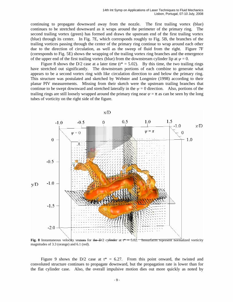
Figure 8 shows the D/2 case at a later time (t* = 5.02). By this time, the two trailing rings have stretched out significantly. The downstream portions of each combine to generate what appears to be a second vortex ring with like circulation direction to and below the primary ring. This structure was postulated and sketched by Webster and Longmire (1998) according to their planar PIV measurements. Missing from their sketch were the upstream trailing branches that continue to be swept downward and stretched laterally in the ψ = 0 direction. Also, portions of the trailing rings are still loosely wrapped around the primary ring near ψ = π as can be seen by the long tubes of vorticity on the right side of the figure.
Fig. 8 Instantaneous velocity vectors for the D/2 cylinder at t* = 5.02. Isosurfaces represent normalized vorticity magnitudes of 3.3 (orange) and 6.1 (red).
Figure 9 shows the D/2 case at t* = 6.27. From this point onward, the twisted and convoluted structure continues to propagate downward, but the propagation rate is lower than for the flat cylinder case. Also, the overall impulsive motion dies out more quickly as noted by

14th Int Symp on Applications of Laser Techniques to Fluid Mechanics Lisbon, Portugal, 07-10 July, 2008
- 10 -
Webster and Longmire (1998). This is not surprising given the interaction between the leading and trailing circulation.
Fig. 9 Instantaneous velocity vectors for the D/2 cylinder at t* = 6.27. Isosurfaces represent normalized vorticity magnitudes of 3.3 (orange) and 6.1 (red).
Sequences of data were also obtained for the D/4 case (not shown due to space limitations). The flow downstream of the D/4 cylinder exhibited coherent vortices (one primary ring and two trailing rings) similar to those observed in the D/2 case, but the interactions between the primary and trailing rings were weaker. For example, the two trailing vortices are also drawn through the center of the primary vortex, but the sweep causing this motion is weaker, and thus, the impact of the trailing vortices on the eventual shape of the primary vortex is less pronounced. In addition to plots of vorticity magnitude, plots of 3D swirl strength were also examined, and the dominant structures observed were quite similar. Therefore, those additional plots are not presented here. 4. Conclusions
Vortex rings generated from cylinders with inclined exits were studied by examining sequences of volumetric velocity fields. The current data, only a portion of which are presented here, show that the interaction between the vortex tubes and the primary vortex ring is more complicated than previously thought, and give a better idea of the flow development, organization, and eventual breakdown mechanism. Webster and Longmire (1998) first studied these flows by examining multiple planes of standard PIV data obtained from separate flow events. From their data, they were able to reconstruct some of the most important characteristics of the flow structure.

14th Int Symp on Applications of Laser Techniques to Fluid Mechanics Lisbon, Portugal, 07-10 July, 2008
- 11 -
The time-evolving V3V data confirm some of their hypotheses, but also reveal significant new details on the vortex formation and interactions.
The previous data of Webster and Longmire documented the presence of vortex tubes in addition to a dominant primary vortex ring. The V3V data show that the additional tubes result from two trailing vortices associated with the stopping of the piston that initiates and drives the original impulse. Initially, the trailing vortices have rotation opposite to the primary ring. However, the trailing vortices interact with one another and the primary vortex ring such that they are stretched and rotated. Parts of the trailing vortices that are eventually swept through the primary ring appear downstream as a coherent secondary ring with a like sense of rotation (as depicted by Webster and Longmire). Image sequences show that additional parts are stretched outward, away from the primary ring in the ψ = 0 direction.
The V3V technique is very useful for studying this type of flow for two reasons. The first is that the resolution of the entire 3D field allows us to place individual structures and events within the context and framework of the rest of the overall flow environment. The second is that the time resolution of the data allows us to track the evolution of dominant and secondary structures. In particular, V3V is valuable for use in flows which exhibit highly complex 3D structures as it elucidates behavior that is difficult to resolve or understand from 2D data. The vortical interactions discussed here are much easier to track and understand by viewing movies of the events from multiple viewing angles, as will be shown at the conference. 5. References Gharib M, Rambod E, Shariff K (1998) A universal time scale for vortex ring formation, J. Fluid Mech. 360:121-140. Krueger PS (2005) An over-pressure correction to the slug model for vortex ring circulation, J. Fluid Mech. 545:427-443. Lim TT (1998) On the Breakdown of Vortex Rings from Inclined Nozzles, Phys. Fluids, 10(7):1666-71. Lim TT, Nickels TB (1995) Vortex rings, In: Fluid Vortices (ed. S. I. Green). Kluwer. Ohmi K, Li HY (2000) Particle tracking velocimetry with new algorithms, Meas. Sci. and Tech., 11(6):603-16. Pereira F, Gharib M, Dabiri D, Modarress D (2000) Defocusing digital particle image velocimetry: a 3-component 3-dimensional DPIV measurement technique. Application to bubbly flows, Exp. Fluids, Suppl S78-S84. Pereira F, Stuer H, Graff EC, Gharib M (2006) Two-frame 3D particle tracking, Meas. Sci. and Tech., 17:1680-1692. Shariff K, Leonard A (1992) Vortex Rings, Ann. Rev. Fluid Mech., 24:235-279. Webster DR, Longmire EK (1998) Vortex Rings From Cylinders with Inclined Exits, Phys. Fluids, 10(2):400-16.